
Technical InformationTI 049D/06/en50097005
Electromagnetic Flow MeasuringSystem – Two-wire, loop-poweredPROline promag 23 P
Flow rate measurement in chemical or process applications
Features and benefits• Nominal diameters DN 25...200• PFA or PTFE lining• PFA for high-temperature applications
up to +180 °C (Ex: up to +150 °C )• Fitting lengths to DVGW and ISO• Measuring accuracy: ± 0.5%• Robust field housing, IP 67, with
separate terminal compartment• “Touch control”: operation without
opening the housing - also for Ex-rated applications
• Communication: HART is standard• Intrinsically safe Ex ia for installation in
zone 1 (ATEX, FM, CSA, etc.)• Transmitter supply:
– Non-Ex environment: 12...30 V DC– Ex environment: 13.9...30 V DC
• Connecting to all mainstream transmit-ter power supplies and input cards of process control systems
• Reduced installation and operation costs
ApplicationAll fluids with a minimum conductivity of ≥ 50 µS/cm can be measured:• acids• alkalis• paints, lacquers• water, etc.
PROline Promag 23 P
2 Endress+Hauser
Function and system design
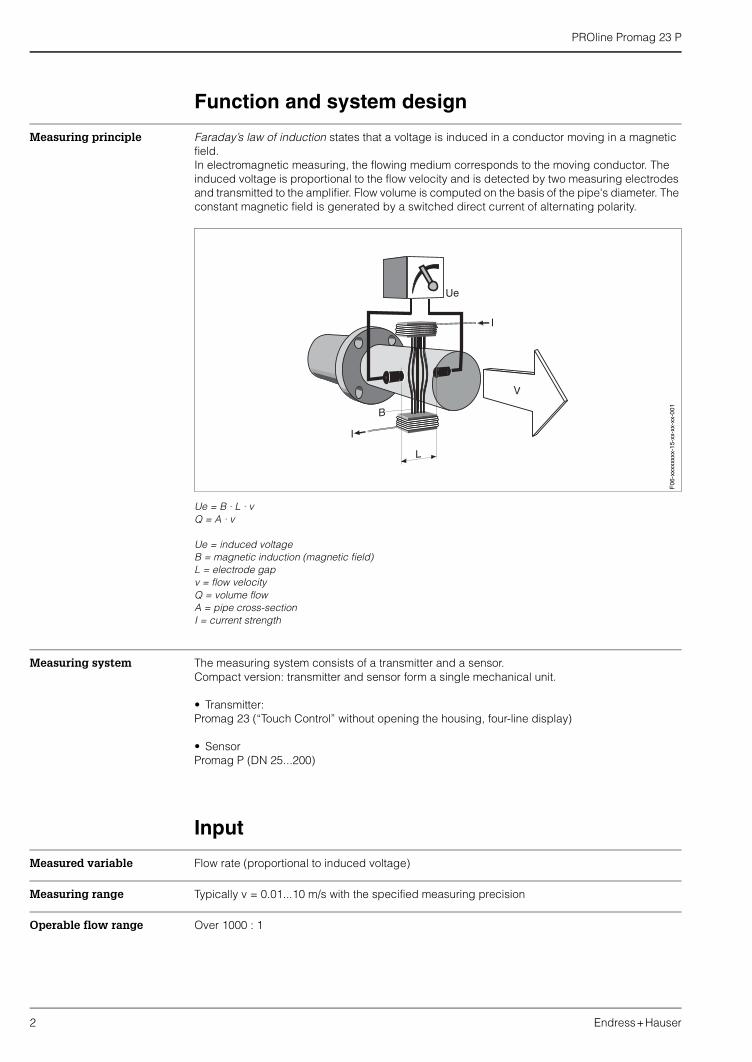
Measuring principle Faraday’s law of induction states that a voltage is induced in a conductor moving in a magnetic field.In electromagnetic measuring, the flowing medium corresponds to the moving conductor. The induced voltage is proportional to the flow velocity and is detected by two measuring electrodes and transmitted to the amplifier. Flow volume is computed on the basis of the pipe's diameter. The constant magnetic field is generated by a switched direct current of alternating polarity.
Ue = B · L · vQ = A · v
Ue = induced voltageB = magnetic induction (magnetic field)L = electrode gapv = flow velocityQ = volume flowA = pipe cross-sectionI = current strength
Measuring system The measuring system consists of a transmitter and a sensor.Compact version: transmitter and sensor form a single mechanical unit.
• Transmitter:Promag 23 (“Touch Control” without opening the housing, four-line display)
• SensorPromag P (DN 25...200)
Input
Measured variable Flow rate (proportional to induced voltage)
Measuring range Typically v = 0.01...10 m/s with the specified measuring precision
Operable flow range Over 1000 : 1
F06
-xxx
xxxx
x-15
-xx-
xx-x
x-00
1
PROline Promag 23 P
Endress+Hauser 3
Output
Output signal • Current output:Applied direct current 4...20 mA, input from DC voltage source.Terminal voltage: 12...30 V DC, 13.9...30 V DC (Ex i)
• Frequency output:Open collector, passive, galvanically isolated, 30 V DC, 100 mA (250 mA / 20 ms)
Optional configurable as:– Frequency output:
Full scale frequency 500...10000 Hz (fmax = 12.5 Hz)or– Pulse output:
Pulse value and pulse polarity adjustable, pulse width adjustable (0.01...10 s), pulse frequency max. 50 Hz
or– Status output:
E.g. for error messages, Empty Pipe Detection, flow direction recognition, limit value configurable
• Ex i version:– Power-supply, signal circuits and pulse output with "intrinsically safe" protection rating,
EEx ia IIC and EEx ia IIB, only for connection to certified, intrinsically safe circuits withthe following maximum values: Ui = 30 V, Ii = 150 mA, Pi = 810 mWEffective internal inductance: negligibleEffective internal capacitance: Ci ≤ 25 nF
– Pulse output:Maximum values: Ui = 30 V, Ii = 10 mA, Pi = 1 WEffective internal inductance: negligibleEffective internal capacitance: negligible
Signal on alarm • Current output → failure response selectable• Pulse/frequency output → failure response selectable• Status output → “non-conductive” by fault or power supply failure
Load see Page 5
Low flow cut off Switch points for low flow cut off are selectable.
Galvanic isolation Outputs are galvanically isolated from sensor and from each other.
PROline Promag 23 P
4 Endress+Hauser
Power supply
Electrical connectionmeasuring unit
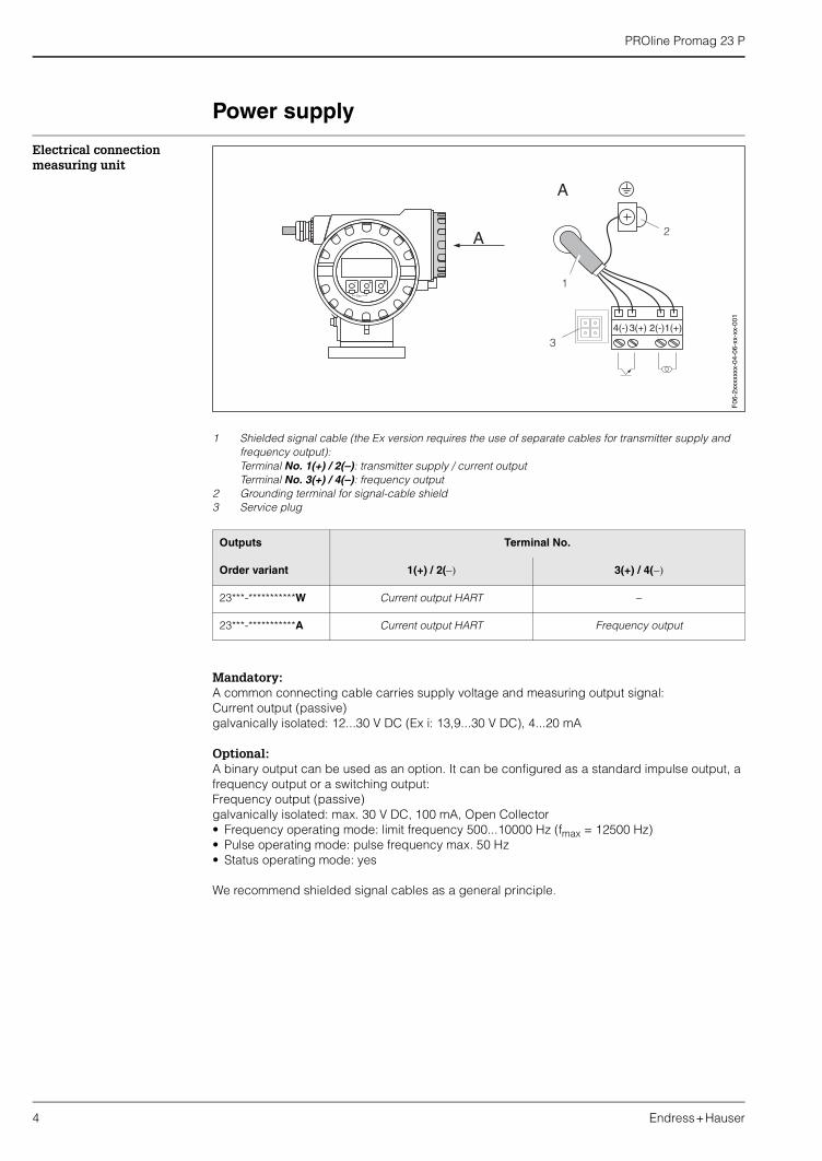
1 Shielded signal cable (the Ex version requires the use of separate cables for transmitter supply and frequency output):Terminal No. 1(+) / 2(–): transmitter supply / current outputTerminal No. 3(+) / 4(–): frequency output
2 Grounding terminal for signal-cable shield3 Service plug
Mandatory:A common connecting cable carries supply voltage and measuring output signal:Current output (passive)galvanically isolated: 12...30 V DC (Ex i: 13,9...30 V DC), 4...20 mA
Optional:A binary output can be used as an option. It can be configured as a standard impulse output, a frequency output or a switching output:Frequency output (passive)galvanically isolated: max. 30 V DC, 100 mA, Open Collector• Frequency operating mode: limit frequency 500...10000 Hz (fmax = 12500 Hz)• Pulse operating mode: pulse frequency max. 50 Hz• Status operating mode: yes
We recommend shielded signal cables as a general principle.
Outputs Terminal No.
Order variant 1(+) / 2(−) 3(+) / 4(−)
23***-***********W Current output HART −
23***-***********A Current output HART Frequency output
Esc
E- +
A
A
2
1
34(-)3(+) 2(-)1(+)
F06
-2xx
xxxx
x-04
-06-
xx-x
x-00
1
PROline Promag 23 P
Endress+Hauser 5
Load The load has to be calculated as follows:
Non Ex area:
Ex area (Ex i):
RL[Ω] = max. load resistance, load(cable resistance)
US[V] = external supply voltage of 12...30 V DC(outgoing supply voltage, transmitter supply unit)
UV[V] = min. supply voltage of 12 V DCmin. supply voltage of 13,9 V DC (Ex i)(required supply voltage, transmitter)
IM[A] = max. signal transmission current(failsafe mode current output: 22 mA max. current)
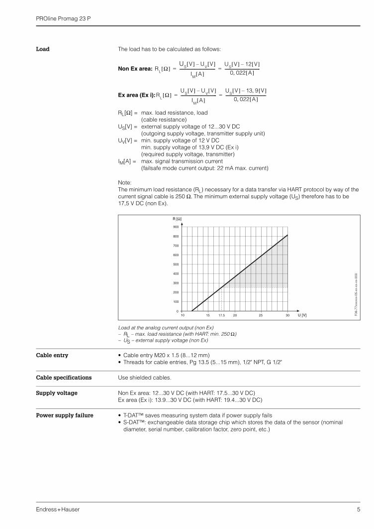
Note:The minimum load resistance (RL) necessary for a data transfer via HART protocol by way of the current signal cable is 250 Ω. The minimum external supply voltage (US) therefore has to be 17,5 V DC (non Ex).
Load at the analog current output (non Ex)– RL – max. load resistance (with HART: min. 250 Ω)– US – external supply voltage (non Ex)
Cable entry • Cable entry M20 x 1.5 (8...12 mm)• Threads for cable entries, Pg 13.5 (5...15 mm), 1/2" NPT, G 1/2"
Cable specifications Use shielded cables.
Supply voltage Non Ex area: 12...30 V DC (with HART: 17.5...30 V DC)Ex area (Ex i): 13.9...30 V DC (with HART: 19.4...30 V DC)
Power supply failure • T-DAT™ saves measuring system data if power supply fails• S-DAT™: exchangeable data storage chip which stores the data of the sensor (nominal
diameter, serial number, calibration factor, zero point, etc.)
RL
Ω[ ]U
SV[ ] U
VV[ ]–
IM
A[ ]--------------------------------------
US
V[ ] 12 V[ ]–0 022 A[ ],
-------------------------------------= =
RL
Ω[ ]U
SV[ ] U
VV[ ]–
IM
A[ ]--------------------------------------
US
V[ ] 13 9 V[ ],–0 022 A[ ],
-------------------------------------------= =
F06-
77xx
xxxx
-05-
xx-x
x-xx
-000
PROline Promag 23 P
6 Endress+Hauser
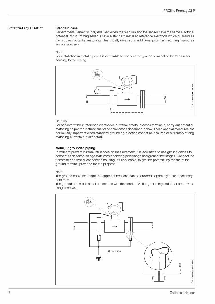
Potential equalisation Standard case Perfect measurement is only ensured when the medium and the sensor have the same electrical potential. Most Promag sensors have a standard installed reference electrode which guarantees the required potential matching. This usually means that additional potential matching measures are unnecessary.
Note:For installation in metal pipes, it is advisable to connect the ground terminal of the transmitter housing to the piping.
Caution:For sensors without reference electrodes or without metal process terminals, carry out potential matching as per the instructions for special cases described below. These special measures are particularly important when standard grounding practice cannot be ensured or extremely strong matching currents are expected.
Metal, ungrounded pipingIn order to prevent outside influences on measurement, it is advisable to use ground cables to connect each sensor flange to its corresponding pipe flange and ground the flanges. Connect the transmitter or sensor connection housing, as applicable, to ground potential by means of the ground terminal provided for the purpose.
Note:The ground cable for flange-to-flange connections can be ordered separately as an accessory from E+H.The ground cable is in direct connection with the conductive flange coating and is secured by the flange screws.
F06
-2xx
xxxx
x-04
-xx-
xx-x
x-00
0
6 mm² Cu
F06
-2xx
xxxx
x-04
-xx-
xx-x
x-00
1
PROline Promag 23 P
Endress+Hauser 7
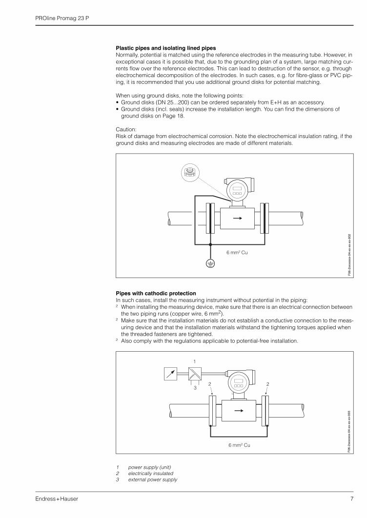
Plastic pipes and isolating lined pipesNormally, potential is matched using the reference electrodes in the measuring tube. However, in exceptional cases it is possible that, due to the grounding plan of a system, large matching cur-rents flow over the reference electrodes. This can lead to destruction of the sensor, e.g. through electrochemical decomposition of the electrodes. In such cases, e.g. for fibre-glass or PVC pip-ing, it is recommended that you use additional ground disks for potential matching.
When using ground disks, note the following points:• Ground disks (DN 25...200) can be ordered separately from E+H as an accessory.• Ground disks (incl. seals) increase the installation length. You can find the dimensions of
ground disks on Page 18.
Caution:Risk of damage from electrochemical corrosion. Note the electrochemical insulation rating, if the ground disks and measuring electrodes are made of different materials.
Pipes with cathodic protectionIn such cases, install the measuring instrument without potential in the piping:² When installing the measuring device, make sure that there is an electrical connection between
the two piping runs (copper wire, 6 mm2).² Make sure that the installation materials do not establish a conductive connection to the meas-
uring device and that the installation materials withstand the tightening torques applied when the threaded fasteners are tightened.
² Also comply with the regulations applicable to potential-free installation.
1 power supply (unit)2 electrically insulated3 external power supply
F06
-2xx
xxxx
x-04
-xx-
xx-x
x-00
2
6 mm² Cu
1
23
2
F06
-2xx
xxxx
x-04
-xx-
xx-x
x-00
3
PROline Promag 23 P
8 Endress+Hauser
Measuring accuracy
Reference operating conditions
To DIN 19200 and VDI/VDE 2641:• Medium temperature: +28 °C ± 2 K• Ambient temperature: +22 °C ± 2 K• Warm-up period: 30 minutes
Installation:• Inlet run >10 x DN• Outlet run > 5 x DN• Sensor and transmitter grounded.• Sensor centered relative to the pipe.
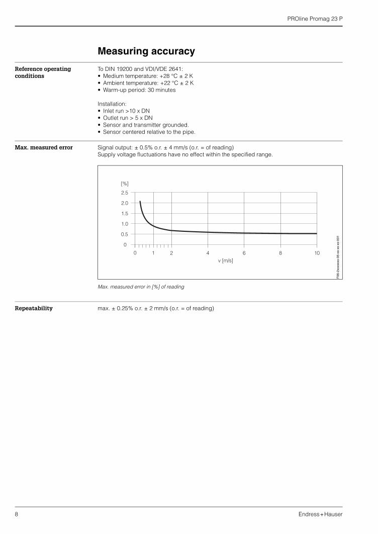
Max. measured error Signal output: ± 0.5% o.r. ± 4 mm/s (o.r. = of reading)Supply voltage fluctuations have no effect within the specified range.
Max. measured error in [%] of reading
Repeatability max. ± 0.25% o.r. ± 2 mm/s (o.r. = of reading)
F06
-2xx
xxxx
x-05
-xx-
xx-x
x-00
1
PROline Promag 23 P
Endress+Hauser 9
Installation conditions
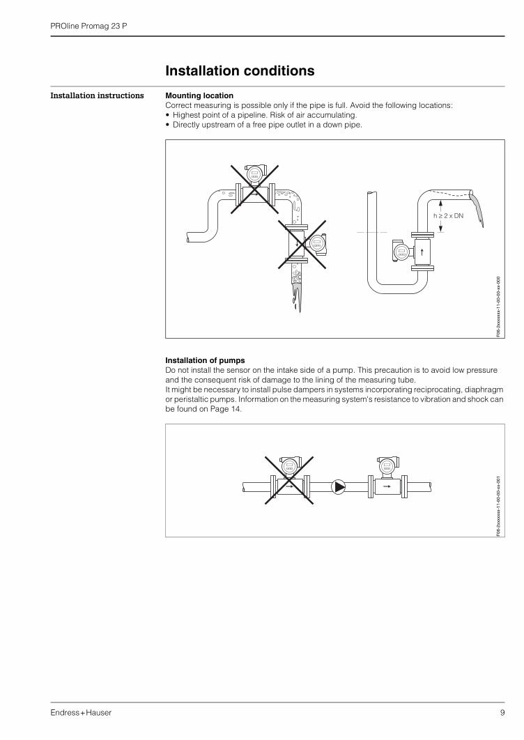
Installation instructions Mounting locationCorrect measuring is possible only if the pipe is full. Avoid the following locations:• Highest point of a pipeline. Risk of air accumulating.• Directly upstream of a free pipe outlet in a down pipe.
Installation of pumpsDo not install the sensor on the intake side of a pump. This precaution is to avoid low pressure and the consequent risk of damage to the lining of the measuring tube.It might be necessary to install pulse dampers in systems incorporating reciprocating, diaphragm or peristaltic pumps. Information on the measuring system's resistance to vibration and shock can be found on Page 14.
F06
-2xx
xxxx
x-11
-00-
00-x
x-00
0F
06-2
xxxx
xxx-
11-0
0-00
-xx-
001
PROline Promag 23 P
10 Endress+Hauser
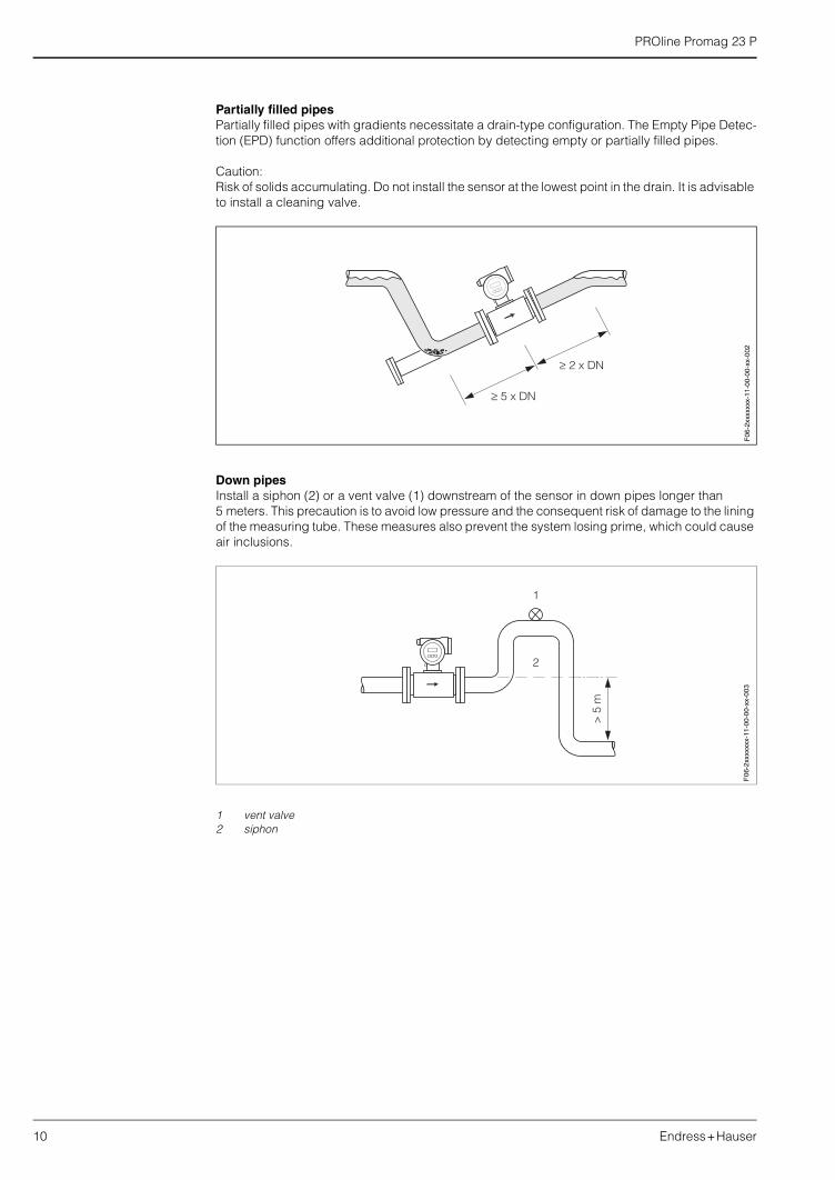
Partially filled pipesPartially filled pipes with gradients necessitate a drain-type configuration. The Empty Pipe Detec-tion (EPD) function offers additional protection by detecting empty or partially filled pipes.
Caution:Risk of solids accumulating. Do not install the sensor at the lowest point in the drain. It is advisable to install a cleaning valve.
Down pipesInstall a siphon (2) or a vent valve (1) downstream of the sensor in down pipes longer than 5 meters. This precaution is to avoid low pressure and the consequent risk of damage to the lining of the measuring tube. These measures also prevent the system losing prime, which could cause air inclusions.
1 vent valve2 siphon
F06
-2xx
xxxx
x-11
-00-
00-x
x-00
2
> 5
m
2
1
F06
-2xx
xxxx
x-11
-00-
00-x
x-00
3
PROline Promag 23 P
Endress+Hauser 11
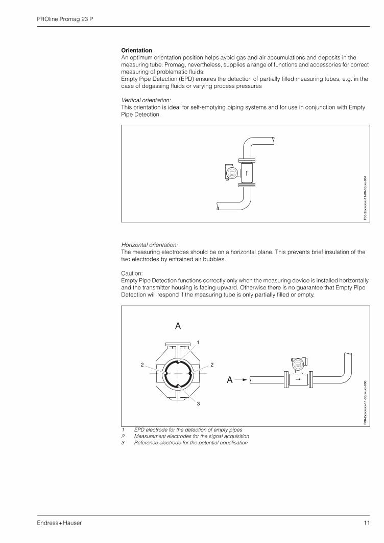
OrientationAn optimum orientation position helps avoid gas and air accumulations and deposits in the measuring tube. Promag, nevertheless, supplies a range of functions and accessories for correct measuring of problematic fluids:Empty Pipe Detection (EPD) ensures the detection of partially filled measuring tubes, e.g. in the case of degassing fluids or varying process pressures
Vertical orientation:This orientation is ideal for self-emptying piping systems and for use in conjunction with Empty Pipe Detection.
Horizontal orientation:The measuring electrodes should be on a horizontal plane. This prevents brief insulation of the two electrodes by entrained air bubbles.
Caution:Empty Pipe Detection functions correctly only when the measuring device is installed horizontally and the transmitter housing is facing upward. Otherwise there is no guarantee that Empty Pipe Detection will respond if the measuring tube is only partially filled or empty.
1 EPD electrode for the detection of empty pipes2 Measurement electrodes for the signal acquisition3 Reference electrode for the potential equalisation
F06
-2xx
xxxx
x-11
-00-
00-x
x-00
4
A
A
1
2 2
3
F06
-2xx
xxxx
x-11
-00-
xx-x
x-00
0
PROline Promag 23 P
12 Endress+Hauser
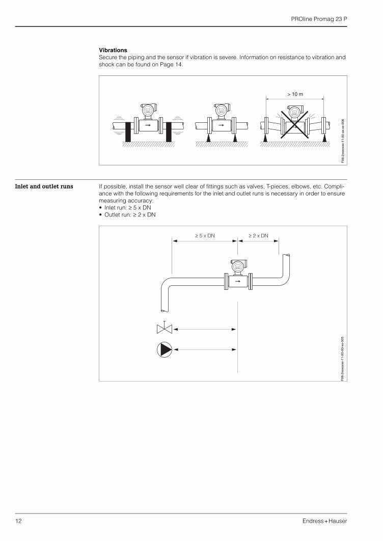
VibrationsSecure the piping and the sensor if vibration is severe. Information on resistance to vibration and shock can be found on Page 14.
Inlet and outlet runs If possible, install the sensor well clear of fittings such as valves, T-pieces, elbows, etc. Compli-ance with the following requirements for the inlet and outlet runs is necessary in order to ensure measuring accuracy:• Inlet run: ≥ 5 x DN• Outlet run: ≥ 2 x DN
F06
-2xx
xxxx
x-11
-00-
xx-x
x-00
6F
06-2
xxxx
xxx-
11-0
0-00
-xx-
005
PROline Promag 23 P
Endress+Hauser 13
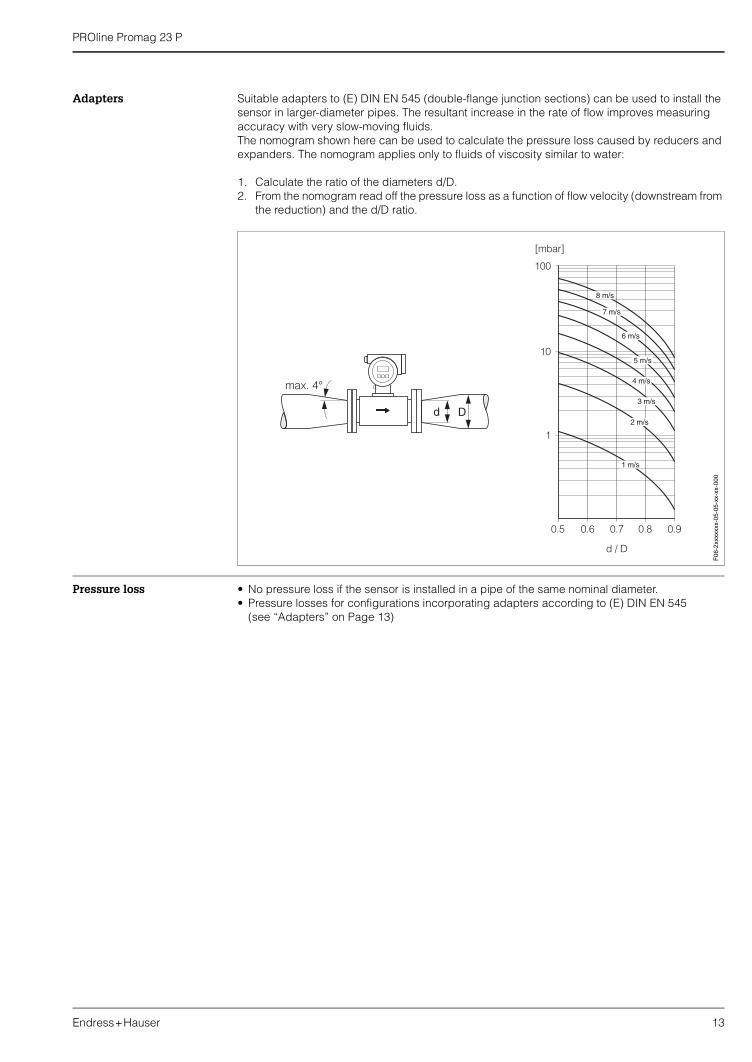
Adapters Suitable adapters to (E) DIN EN 545 (double-flange junction sections) can be used to install the sensor in larger-diameter pipes. The resultant increase in the rate of flow improves measuring accuracy with very slow-moving fluids. The nomogram shown here can be used to calculate the pressure loss caused by reducers and expanders. The nomogram applies only to fluids of viscosity similar to water:
1. Calculate the ratio of the diameters d/D.2. From the nomogram read off the pressure loss as a function of flow velocity (downstream from
the reduction) and the d/D ratio.
Pressure loss • No pressure loss if the sensor is installed in a pipe of the same nominal diameter.• Pressure losses for configurations incorporating adapters according to (E) DIN EN 545
(see “Adapters” on Page 13)
F06
-2xx
xxxx
x-05
-05-
xx-x
x-00
0
PROline Promag 23 P
14 Endress+Hauser
Ambient conditions
Ambient temperature −20...+60 °C
Install the device at a shady location. Avoid direct sunlight, particularly in warm climatic regions.
Storage temperature –10...+50 °C (preferably +20 °C)
Degree of protection IP 67 (NEMA 4X)
Shock and vibration resistance
Acceleration up to 2 g by analogy with IEC 68-2-6(High temperature version: no appropriate data available)
Electromagnetic compatibility (EMC)
To EN 61326 and NAMUR recommendation NE 21
Process conditions
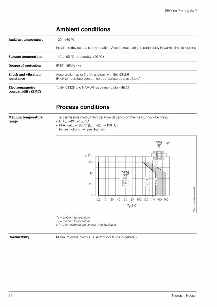
Medium temperature range
The permissible medium temperature depends on the measuring-tube lining:• PTFE: –40...+130 °C• PFA: –20...+180 °C (Ex i: –20...+150 °C)
for restrictions → see diagram
TA = ambient temperatureTF = medium temperatureHT = high temperature version, with insulation
Conductivity Minimum conductivity ≥ 50 µS/cm (for fluids in general)
0
0
-20 20
20
40
60
TA [°C]
40 60 80
TF [°C]
100 120 140 160 180
HT
PFA
PTFE
F06
-2xP
xxxx
x-05
-xx-
xx-x
x-00
0
PROline Promag 23 P
Endress+Hauser 15
Medium pressure range(nominal pressure)
DIN 2501:PN 10 (DN 200)PN 16 (DN 65...200)PN 25 (DN 200)PN 40 (DN 25...150)
ANSI B16.5:Class 150 (1...8")Class 300 (1...8")
JIS B2238:10K (DN 50...200)20K (DN 25...200)
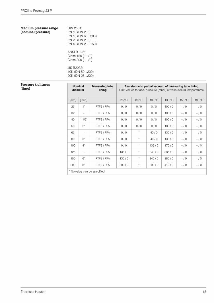
Pressure tightness(liner)
Nominal diameter
Measuring tube lining
Resistance to partial vacuum of measuring tube liningLimit values for abs. pressure [mbar] at various fluid temperatures
[mm] [inch] 25 °C 80 °C 100 °C 130 °C 150 °C 180 °C
25 1" PTFE / PFA 0 / 0 0 / 0 0 / 0 100 / 0 − / 0 − / 0
32 − PTFE / PFA 0 / 0 0 / 0 0 / 0 100 / 0 − / 0 − / 0
40 1 1/2" PTFE / PFA 0 / 0 0 / 0 0 / 0 100 / 0 − / 0 − / 0
50 2" PTFE / PFA 0 / 0 0 / 0 0 / 0 100 / 0 − / 0 − / 0
65 − PTFE / PFA 0 / 0 * 40 / 0 130 / 0 − / 0 − / 0
80 3" PTFE / PFA 0 / 0 * 40 / 0 130 / 0 − / 0 − / 0
100 4" PTFE / PFA 0 / 0 * 135 / 0 170 / 0 − / 0 − / 0
125 − PTFE / PFA 135 / 0 * 240 / 0 385 / 0 − / 0 − / 0
150 6" PTFE / PFA 135 / 0 * 240 / 0 385 / 0 − / 0 − / 0
200 8" PTFE / PFA 200 / 0 * 290 / 0 410 / 0 − / 0 − / 0
* No value can be specified.
PROline Promag 23 P
16 Endress+Hauser
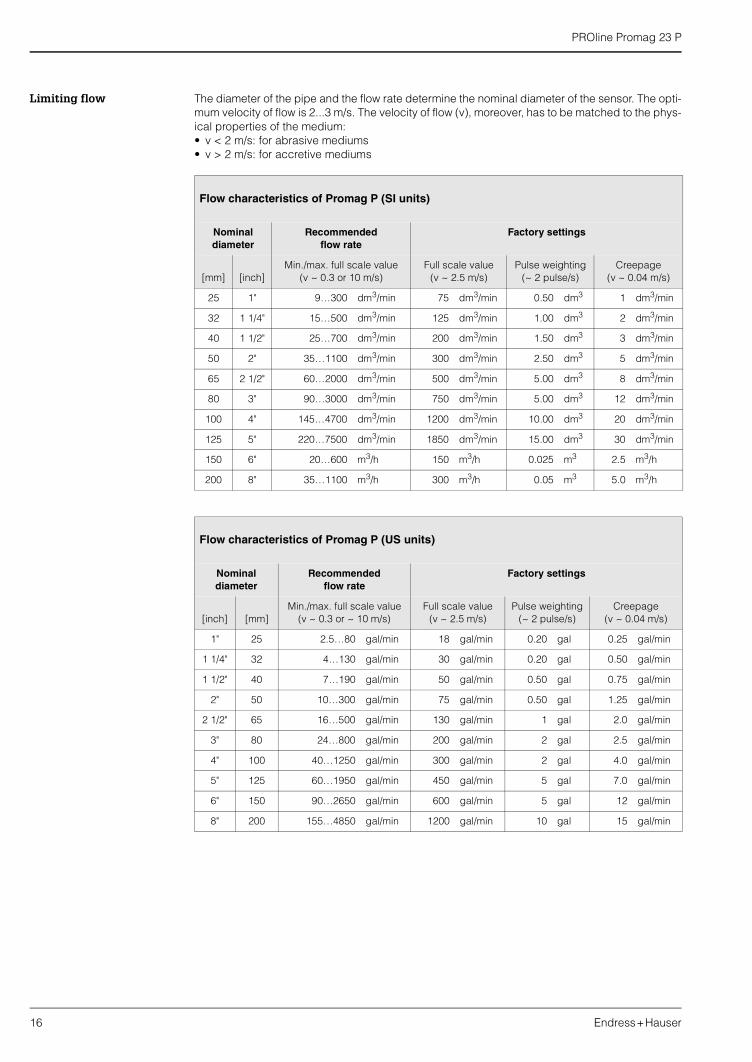
Limiting flow The diameter of the pipe and the flow rate determine the nominal diameter of the sensor. The opti-mum velocity of flow is 2...3 m/s. The velocity of flow (v), moreover, has to be matched to the phys-ical properties of the medium:• v < 2 m/s: for abrasive mediums• v > 2 m/s: for accretive mediums
Flow characteristics of Promag P (SI units)
Nominal diameter
Recommendedflow rate
Factory settings
[mm] [inch]Min./max. full scale value
(v ~ 0.3 or 10 m/s)Full scale value
(v ~ 2.5 m/s)Pulse weighting
(~ 2 pulse/s)Creepage
(v ~ 0.04 m/s)
25 1" 9…300 dm3/min 75 dm3/min 0.50 dm3 1 dm3/min
32 1 1/4" 15…500 dm3/min 125 dm3/min 1.00 dm3 2 dm3/min
40 1 1/2" 25…700 dm3/min 200 dm3/min 1.50 dm3 3 dm3/min
50 2" 35…1100 dm3/min 300 dm3/min 2.50 dm3 5 dm3/min
65 2 1/2" 60…2000 dm3/min 500 dm3/min 5.00 dm3 8 dm3/min
80 3" 90…3000 dm3/min 750 dm3/min 5.00 dm3 12 dm3/min
100 4" 145…4700 dm3/min 1200 dm3/min 10.00 dm3 20 dm3/min
125 5" 220…7500 dm3/min 1850 dm3/min 15.00 dm3 30 dm3/min
150 6" 20…600 m3/h 150 m3/h 0.025 m3 2.5 m3/h
200 8" 35…1100 m3/h 300 m3/h 0.05 m3 5.0 m3/h
Flow characteristics of Promag P (US units)
Nominaldiameter
Recommendedflow rate
Factory settings
[inch] [mm]Min./max. full scale value
(v ~ 0.3 or ~ 10 m/s)Full scale value
(v ~ 2.5 m/s)Pulse weighting
(~ 2 pulse/s)Creepage
(v ~ 0.04 m/s)
1" 25 2.5…80 gal/min 18 gal/min 0.20 gal 0.25 gal/min
1 1/4" 32 4…130 gal/min 30 gal/min 0.20 gal 0.50 gal/min
1 1/2" 40 7…190 gal/min 50 gal/min 0.50 gal 0.75 gal/min
2" 50 10…300 gal/min 75 gal/min 0.50 gal 1.25 gal/min
2 1/2" 65 16…500 gal/min 130 gal/min 1 gal 2.0 gal/min
3" 80 24…800 gal/min 200 gal/min 2 gal 2.5 gal/min
4" 100 40…1250 gal/min 300 gal/min 2 gal 4.0 gal/min
5" 125 60…1950 gal/min 450 gal/min 5 gal 7.0 gal/min
6" 150 90…2650 gal/min 600 gal/min 5 gal 12 gal/min
8" 200 155…4850 gal/min 1200 gal/min 10 gal 15 gal/min
PROline Promag 23 P
Endress+Hauser 17
Mechanical construction
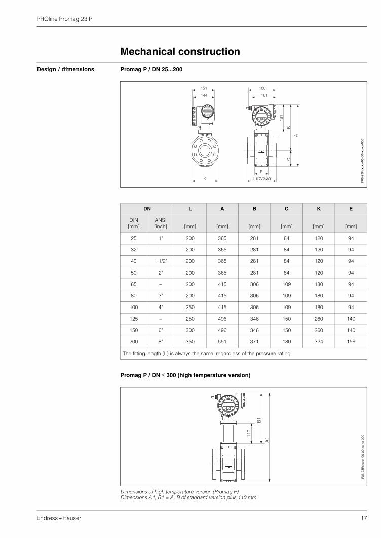
Design / dimensions Promag P / DN 25...200
Promag P / DN ≤ 300 (high temperature version)
Dimensions of high temperature version (Promag P)Dimensions A1, B1 = A, B of standard version plus 110 mm
DN L A B C K E
DIN[mm]
ANSI[inch] [mm] [mm] [mm] [mm] [mm] [mm]
25 1" 200 365 281 84 120 94
32 − 200 365 281 84 120 94
40 1 1/2" 200 365 281 84 120 94
50 2" 200 365 281 84 120 94
65 − 200 415 306 109 180 94
80 3" 200 415 306 109 180 94
100 4" 250 415 306 109 180 94
125 − 250 496 346 150 260 140
150 6" 300 496 346 150 260 140
200 8" 350 551 371 180 324 156
The fitting length (L) is always the same, regardless of the pressure rating.
F06
-23F
xxxx
x-06
-00-
xx-x
x-00
0
A1
B1
110
Esc
E- +
F06-
23P
xxxx
x-06
-00-
xx-x
x-00
0
PROline Promag 23 P
18 Endress+Hauser
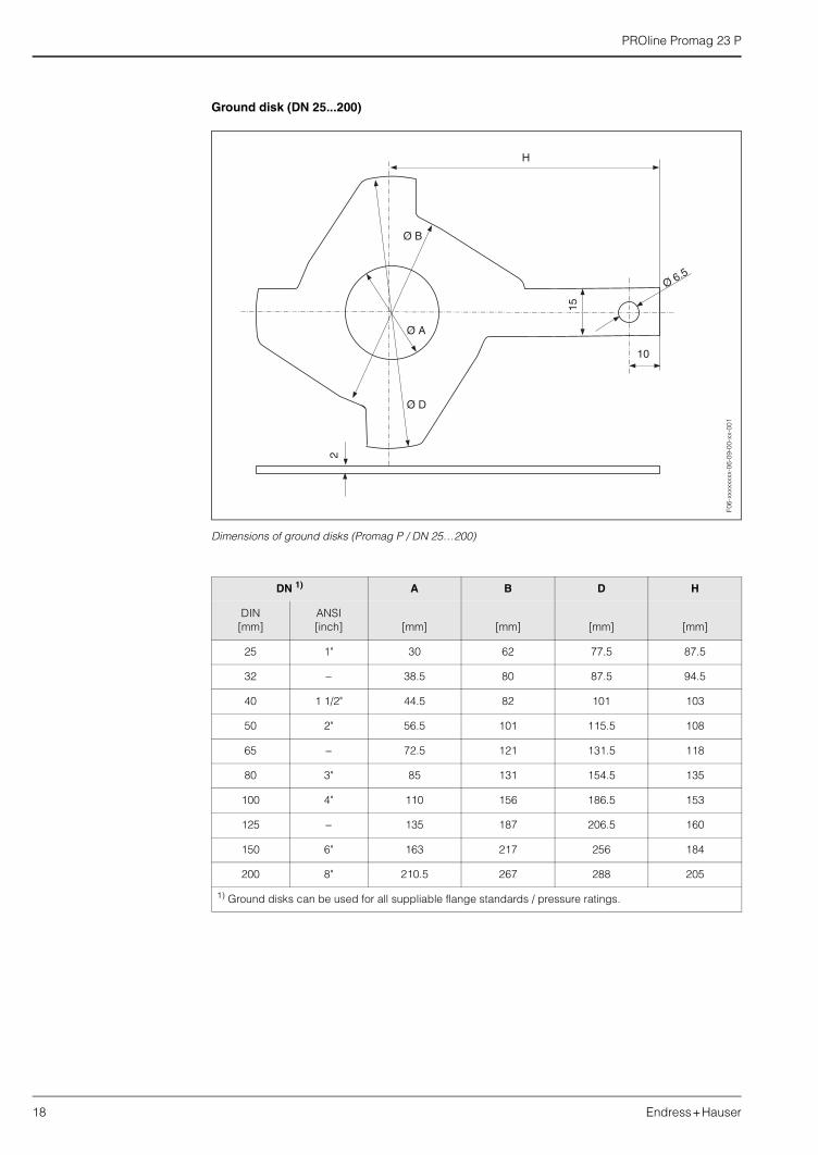
Ground disk (DN 25...200)
Dimensions of ground disks (Promag P / DN 25…200)
DN 1) A B D H
DIN[mm]
ANSI[inch] [mm] [mm] [mm] [mm]
25 1" 30 62 77.5 87.5
32 − 38.5 80 87.5 94.5
40 1 1/2" 44.5 82 101 103
50 2" 56.5 101 115.5 108
65 − 72.5 121 131.5 118
80 3" 85 131 154.5 135
100 4" 110 156 186.5 153
125 − 135 187 206.5 160
150 6" 163 217 256 184
200 8" 210.5 267 288 205
1) Ground disks can be used for all suppliable flange standards / pressure ratings.
15
10
H
Ø B
Ø A
Ø D
Ø 6.5
2
F06-
xxxx
xxxx
-06-
09-0
0-xx
-001
PROline Promag 23 P
Endress+Hauser 19
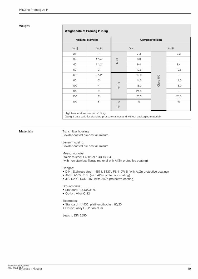
Weight
Materials Transmitter housing:Powder-coated die-cast aluminum
Sensor housing:Powder-coated die-cast aluminum
Measuring tube:Stainless steel 1.4301 or 1.4306/304L(with non-stainless flange material with AI/Zn protective coating)
Flanges:• DIN : Stainless steel 1.4571, ST37 / FE 410W B (with Al/Zn protective coating)• ANSI: A105, 316L (with Al/Zn protective coating)• JIS: S20C, SUS 316L (with Al/Zn protective coating)
Ground disks:• Standard: 1.4435/316L• Option: Alloy C-22
Electrodes:• Standard: 1.4435, platinum/rhodium 80/20• Option: Alloy C-22, tantalum
Seals to DIN 2690
Weight data of Promag P in kg
Nominal diameter Compact version
[mm] [inch] DIN ANSI
25 1"
PN
40
7,3
Cla
ss 1
50
7,3
32 1 1/4" 8,0 –
40 1 1/2" 9,4 9,4
50 2" 10,6 10,6
65 2 1/2"
PN
16
12,0 –
80 3" 14,0 14,0
100 4" 16,0 16,0
125 5" 21,5 –
150 6" 25,5 25,5
200 8"
PN
10 45 45
High temperature version: +1.5 kg(Weight data valid for standard pressure ratings and without packaging material)
TI 049D/06/en/05.00FM+SGML 5.5
PROline Promag 23 P
20 Endress+Hauser
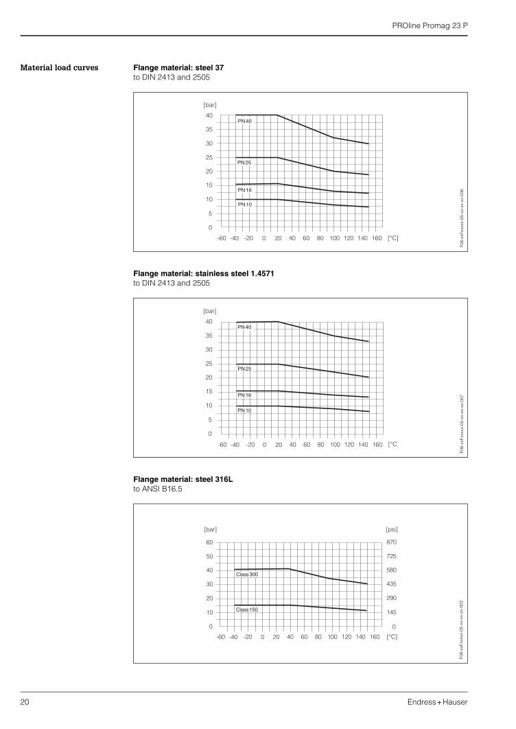
Material load curves Flange material: steel 37to DIN 2413 and 2505
Flange material: stainless steel 1.4571to DIN 2413 and 2505
Flange material: steel 316Lto ANSI B16.5
0
5
10
15
20
25PN 25
PN 16
PN 10
35
30
40PN 40
[bar]
-60 -40 -20 0 20 40 60 80 100 120 140 160 [°C]
F06-
xxFx
xxxx
-05-
xx-x
x-xx
-006
0
5
10
15
20
25PN25
PN16
PN10
35
30
40PN40
[bar]
-60 -40 -20 0 20 40 60 80 100 120 140 160 [°C]
F06-
xxFx
xxxx
-05-
xx-x
x-xx
-007
F06-
xxFx
xxxx
-05-
xx-x
x-xx
-002
PROline Promag 23 P
Endress+Hauser 21
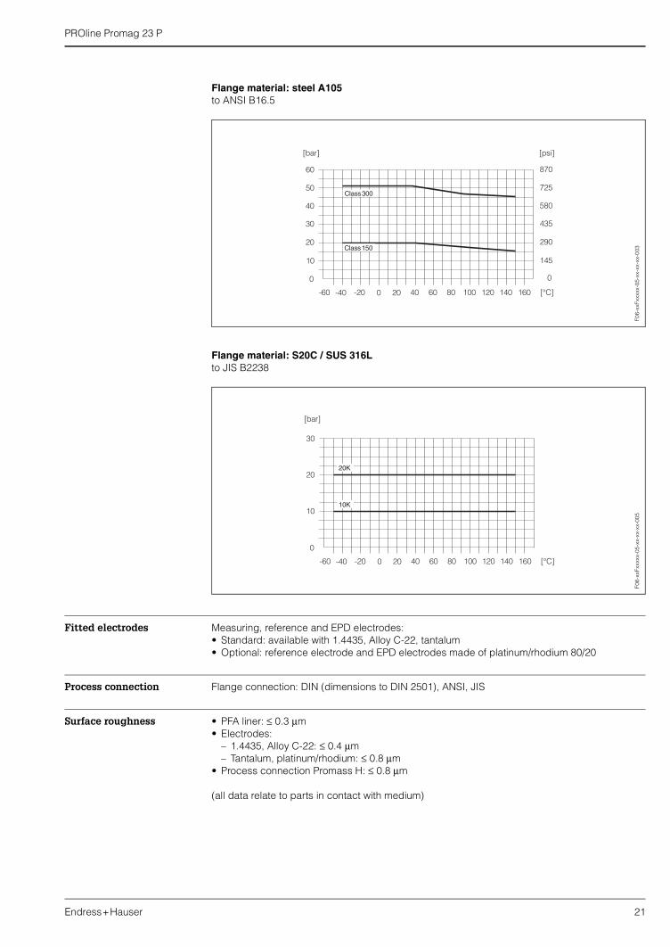
Flange material: steel A105to ANSI B16.5
Flange material: S20C / SUS 316Lto JIS B2238
Fitted electrodes Measuring, reference and EPD electrodes:• Standard: available with 1.4435, Alloy C-22, tantalum• Optional: reference electrode and EPD electrodes made of platinum/rhodium 80/20
Process connection Flange connection: DIN (dimensions to DIN 2501), ANSI, JIS
Surface roughness • PFA liner: ≤ 0.3 µm• Electrodes:
– 1.4435, Alloy C-22: ≤ 0.4 µm – Tantalum, platinum/rhodium: ≤ 0.8 µm
• Process connection Promass H: ≤ 0.8 µm
(all data relate to parts in contact with medium)
F06-
xxFx
xxxx
-05-
xx-x
x-xx
-003
F06-
xxFx
xxxx
-05-
xx-x
x-xx
-005
PROline Promag 23 P
22 Endress+Hauser
Human interface
Display elements • Liquid-crystal display: four lines with 16 characters per line• Custom configurations for presenting different measured values and status variables• 2 totalizers
Operating elements Unified (PROline-) operation concept:Local operation with three optical keys (–, +, E)
Remote operation Operation via HART
Certificates and approvals
Ex approval Information on the currently available Ex-rated versions (ATEX, FM, CSA, etc.) is available on request from your E+H sales outlet. All information relevant to explosion protection is available in separate Ex documents that you can order as necessary.
CE mark The measuring system is in conformity with the statutory requirements of the EC Directives. Endress+Hauser confirms successful testing of the device by affixing to it the CE mark.
Other standards and guidelines
EN 60529:Degrees of protection by housing (IP code)
EN 61010:“Protection Measures for Electrical Equipment for Measurement, Control, Regulation and Labora-tory Procedures”.
EN 61326 (IEC 1326):Electromagnetic compatibility (EMC requirements)
NAMUR NE 21:Association for Standards for Control and Regulation in the Chemical Industry
Ordering information
The E+H service organization can provide detailed ordering information and information on the order codes on request.
Accessories
Various accessories, which can be ordered separately from Endress+Hauser, are available for the transmitter and the sensor. The E+H service organisation can provide detailed information on request.

PROline Promag 23 P
Endress+Hauser 23
Supplementary documentation
System Information Promag (SI 028D/06/en) Technical Information Promag 23 H (TI 051D/06/en) Operating Instructions Promag 23 (BA 045D/06/en and BA 050D/06/en) Supplementary documentation on Ex-ratings: ATEX, FM, CSA, etc.

Endress+HauserGmbh+Co.Instruments InternationalP.O. Box 2222D-79574 Weil am RheinGermany
Tel. (07621) 975-02Tx 773926Fax (07621) 975 345http://[email protected]
TI 049D/06/en/08.0150097005FM+SGML 6.0
Subject to modification
Recommended