EISWIER Automation in Construction 5 (1997) 393406
Programming construction robots using virtual reality techniques ’
R. Navon a92, A. Retik b33
a Technion. Department of Civil Engineering, National Building Research Institute, Technion City, 32000 Haifa, Israel b Department of Civil Engineering, University of Stratchylde, Glasgow G4 ONG, UK
Abstract
The paper describes a new approach to programming construction robots, using virtual reality (VR) techniques. The new approach is needed because both traditional and new methods of programming industrial robots, described in the paper, have
specific drawbacks, which become crucial in the construction arena. This is because of the ever-changing environment of construction and its nature, a prototype or one-of-a-kind, industry. As a result, construction robots need much more programming than their industrial counterparts, which is labor intensive using known methods and is not compensated by mass production. The VR approach is demonstrated with the Multi-Purpose Interior Finishing Robot (MPIR) for a masonry task, accompanied by a detailed description of the VR-based programming model and approach.
Keywords: Automation; 13uilding; Construction; Programming; Robot; Virtual reality
1. Introduction
The objective of this paper is to suggest a new method for robot programming with the aid of vir-
tual reality (VR) technology, which allows the fol- lowing to be achieved: 1. Learn geometry and spatial arrangements of a
given design.
’ Discussion is open until August 1997 (please submit your
discussion paper to the Editor on Construction Technologies and
Engineering, M.J. Skibniewski). ’ Tel: + 972-4-8292600; Fax: + 972-4-8324534; e-mail:
cvronie@ tx.technion.ac.il; Internet:
http://techunix.technion.ac.il/ - cvronie. 3 Tel.: + +44-141-552-4400; fax: + +44141-552-0112; e-
m ail: a.retik@ stratch.ac.uk; Internet:
http//www.strath.ac.uk,/Departments/Civeng/conman/cm.html.
Explore the best way for a robot to perform a task using human reasoning. Check and verify structural and organizational safety issues of a robot, including location of
materials. Train the robot for its designated tasks, in the same way as workers would have been trained to
perform new tasks. Robots are considered as flexible manufacturing , .
machines because they can easily be (re)programmed to perform different tasks. Yet, often the complexity of the programming process limits more widespread use of robotic technology [ 11. Researchers and practi- tioners alike are constantly looking for new methods of programming robots to save programming time and costs. This section reviews some common and novel programming techniques used or developed for
0926-5805/97/$17.00 Copyright 0 1997 Elsevier Science B.V. All rights reserved.
PII SO926-5805(96)00162-8
394 R. Nauon, A. Retik/Automation in Construction 5 (1997) 393-406
manufacturing robotics. These techniques are exam- ined for their potential use for construction robots, which operate in an ever-changing environment, pro- ducing one-of-a-kind or at best small-batch products.
1. I. Native programming languages
Currently, most commercial robots are pro-
grammed in textual robot programming languages (RPLs) similar to BASIC, PASCAL, etc. Popular
examples include VAL, RAIL and AML [2]. These languages include positioning instructions, process
parameters and other instructions [3]. RPLs contain primitives to express manipulator motion in world coordinates as a location (x, y, z> and orientation (roll, pitch, yaw) 141. Most languages also contain higher level control commands.
A program in RPL can be written when the robot is in its designated work location (on-line program- ming). The advantage of doing so is that program-
ming is relatively easy, but during programming the robot and the dependent equipment are idle, thus increasing programming costs significantly. Off-line
programming is supposed to solve this problem but it is very difficult to carry out without visual aids. Lees
and Leifer [2] state that describing a robot’s motion through space is not the strength of RPLs (in both the on- and off-line modes). It is difficult for a human to envisage the position and orientation of a robot by merely looking at a string of numbers and it is all but impossible to envisage the robot’s spatial relationship with the rest of the objects in its workspace. Since the basic components of a robot programming language are so counter-intuitive, a complete manipulation program is even more so.
This technique is most unsuitable for program- ming of construction robots due to the complex nature of the construction work. In order to program a construction robot using this technique, the pro- grammer would have to visualize in his/her mind the entire project, including the location of all robot workstations, the locations of the raw materials, etc. In addition, he/she would have to visualize the robot’s reaction to various commands and its interac- tion with the changing environment. No less impor- tant is the fact that programming this way is labor intensive - because of the one-of-the-kind nature of the construction work - and consequently expensive.
1.2. Programming with the aid of graphic simulators
Off-line programming with simulators enables the programmer to write a program without recourse to the robot itself. It is done in a computer-graphic environment, enabling the programmer to preview, debug and verify the program before the robot is
installed, or even bought. Simulators enable the de- velopment of typical tasks, examine different altema- tives to perform them, test different control strate-
gies, explore raw material supply alternatives, etc. Once a program is written, the programmer can visualize the robot’s task being performed, check the planned paths’ suitability for the performance of specific tasks, check that the robot does not collide with other components in the work cell, etc. When the programmer is satisfied with the program, it is translated into the robot’s native language and down- loaded to it.
One of the most important characteristics of graphic simulators is that they are able to measure cycle times, which is an important parameter influ-
enced by the selected paths, by the control algo- rithms, by the material supply method, etc. Thus higher quality programs can be developed with the aid of graphic simulators, taking into account robot productivity as well. However, simulators still re- quire the users to work with text-based languages and consequently only solve part of the problems associated with native robot programming languages
La. Graphic simulators also aid in selecting the best
robot for a given task. Robot selection is based on a number of parameters, such as cycle time, work envelope, path limitations, joint singularities, re- quired floor area, etc. Most of those parameters cannot be checked with a reasonable level of accu- racy and certainty without a graphic simulation sys- tem.
Construction robot programming using graphic simulators offers a meaningful improvement to RPL techniques by enabling the programmer to see both the environment and the robot during programming. While this solves the visualization problem, it still does not decrease the amount of work involved in programming the robot because the commands re- main very basic (positioning instructions, manipula- tor motion instructions, end effector operations, etc.).
R. Nauon, A. Retik/Automation in Construction 5 (1997) 393-406 395
Consequently, this technique is not suitable for con- struction robot programming.
1.3. Additional programming methods
prehensive solution to the complex problem of pro- gramming construction robots, it is merely suggest- ing an additional idea, which can be used either on its own or with other methods, some of which were reviewed above.
Programming by example, or by human demon-
stration, is an intuitive method. The programmer demonstrates how the task is performed using a human/robot teaching device that measures the hu-
man’s forces and positions [l]. The data gathered from the human is used to generate the robot’s
program.
2. VR iu building construction
The goal in automatic robot programming is to
get the robot to perform a task by telling it what needs to be done, rather than by explicitly program-
ming it [51. An approach to automatic robot program- ming was suggested by Rogalinski [6].
Visual robot programming is a term applied to
systems which allow programming in a two- or three-dimensional manner [7]. A visual demonstra- tion of the task is performed not in the real world but
within the digitized images that the robot’s vision system sees. The programmer indicates directly in the digitized images (using a mouse) robot actions,
constituent parts, grip points, relative orientations, approach routes, etc. Complex task-planning by the robot is avoided by keeping the human in the control loop, thus the human problem solving skills support the robot’s understanding and execution of the task.
VR is an advanced computer graphics technology dealing with visualization [8]. As a computer graph- ics application it can be used for a wide variety of
uses, e.g. [9-121. The use of object-oriented tech- niques for creating virtual environments was the key for a breakthrough in the credibility and applicability of VR technology [ 131. Various definitions exist: one which is both descriptive and short is by Pimentel and Teixeira [ 141 who define VR as “the place where humans and computers make a contract”. Similarly, Larijani 1131 defines VR as the conver- gence of computer simulation and visualization that attempts to eliminate separation between a user and a
machine. From their viewpoint, VR is an interface between humans and computers.
The suitability of the additional techniques, which
are still under development, for construction pur- poses has to be examined when they become com- mercial, or as a separate study. Some of them, such as programming by example, seem unsuitable a pri-
ori. Clearly, the above-mentioned programming meth-
ods and techniques for construction robots are un- suitable which makes them cost ineffective. Other
methods must be developed.
There are two major approaches to creating such an interface: immersive and non-immersive. In im- mersive VR the interface acts as a contact point between a user and machine (system) where the user’s movements are translated into commands that direct the machine’s operation and, in addition, the machine’s simulated condition is communicated to the user through his/her senses (currently mainly through vision). A flight simulator is probably the oldest example of a VR system of this kind. To
achieve effective immersion, a VR system requires not only navigation and manipulation abilities, but also a close correspondence between input and out- put devices such as a glove, a head-mounted display, a pressure-sensitive floor, etc.
The research underlying this paper is planned as a A virtual world can also be explored without multi-stage program. In the first stage the basic tools immersion. Desktop and projection VR systems re-
were built and experimented with using two tech- tain the navigation and manipulation features, giving niques, as will be explained below. The objective of a user the ability to move around the virtual world
this paper is to pmpose the idea of using VR for and manipulate its components using a spaceball, 3D robot programming. as a stimulating idea and to mouse or a simple joystick. Moreover, such non-im- provide some insights from the preliminary experi- mersive applications can have advantages over
ments. The paper does not intend to present a com- “real” VR systems especially in big virtual worlds
396 R. Naaon, A. Retik/Automation in Construction 5 (1997) 393-406
like a typical construction site. Being able to over- look the site from outside (an aerial view) is often more beneficial than to be a small part of the site [15,16].
Visualization and simulation of the construction process using non-immersive projection VR, as
demonstrated in [ 161, may assist a construction plan- ner or a user to improve his/her perception of a
project, as well as to integrate other involved parties in the planning process. In large-scale projects not only the construction process itself can be monitored, but also all the auxiliary activities, including on-site plant and equipment. In addition the different loca- tions of the construction equipment and the tempo- rary facilities can be checked by placing “real” three-dimensional models into a virtual construction site. Then both location changes and operational movements can be verified by simulating a project’s
time schedule. In such cases, especially in projects where heavy equipment is used, clashes and interfer-
ences may be more easily identified [ 171. VR can be applied in building design and con-
struction for a wide variety of uses as proposed in [ 18-231 and others. During the design stages, immer- sive virtual reality systems provide the best way to learn and experience a design to be constructed. Then, during the planning and scheduling of the virtual project, a construction manager is presented with an opportunity to test different construction methods applying value engineering techniques and checking constructability aspects of the construction process to select the best alternative.
Another important use of an immersive VR sys- tem is its ability to provide training facilities for construction staff. The training which can be done with VR, due to its real time capabilities, is the most realistic situation that a person could encounter with- out actually taking part in the task itself.
Comparing the immersive and non-immersive types of VR, a distinction can be drawn between their potential uses within construction applications. Immersive VR is the better solution for training purposes as it provides a far clearer and more exact representation of the real site environment, whereas non-immersive VR would be ideal for simulating site operations as it would allow activities and equipment within the site to be modeled.
There are already several research projects inves-
tigating the use of VR as a tool for design and control of robots. For example, the VERDEX project [24] evaluated the use of VR as an interaction tool
between human operators and semi-autonomous robots to be deployed in hazardous environments, disaster areas and space.
Coiffet [25] presents three main difficulties in the current robotic-applications structure and points out where “VR can deliver either an improvement or a
new efficient approach”. These difficulties are: * the difference in behavior between what is fore-
cast and what is really happening as a result of incorrectness in the matter of robot environment modeling;
- the impossibility of understanding environments
by mobile autonomous robots; - the complexity of teleoperation, which requires
sensory and mechanical adaptations, as well as decision support to the human operator. To eliminate the first difficulty, the design of new
robots can be assisted by VR, both in its geometric
aspects (link dimensions, work envelope, etc.) as well as in its control aspects, such as visualizing sensor data, virtual navigation controller, etc. [ 14,261.
There are two main approaches supplementing each other, to deal with the last two difficulties. One is to assist a remote robot operator using VR tech- nology as a telepresence tool [24,27]. This approach can also help in operators’ training [28]. Another approach is to use VR as a tool for robot task planning, supporting off-line programming for both
navigation simulation and task execution [29-3 I]. Current research into the application of VR in
construction robotics has mainly concentrated on the simulation of robot tasks, checking their feasibility and possible improvement. This paper suggests an approach to planning and off-line programming of robot tasks and demonstrates it with a prototype system.
3. Present-day programming of construction robots
This section explains the present-day approach to programming construction robots, as a necessary background to understand the proposed method (Sec- tion 4). It does so for the Multi-Purpose Interior
R. Nauon, A. Retik/Automation in Construction 5 (1997) 393-406
Finishing Robot (MPIR), which was selected to demonstrate the approach of VR-based programming of construction robots.
MPIR’s working environment is a building skele- ton, which was erected by industrialized methods, such as prefabrication [32]. Two reasons underlie this approach. The first i,s that robotic execution is best done in a more precise environment than that
achieved by conventional construction methods. The second reason is that presently the interior finishing tasks are the Achilles’ heel of the conventional con-
struction methods, while the skeleton, especially when performed with industrialized methods, is con- structed quite satisfactorily. Thus MPIR comple- ments the industriahzed methods. MPIR is desig- nated to perform tasks such as masonry, plastering, painting, joint sealing, tile setting, etc.
3.1. Conuentional programming of construction
robots
Presently, MPIR’s operational concept is that it operates from stationary workstations, which means
that while it performs the actual task, it is stationary. When the task is completed, MPIR moves to the next workstation to perform the task there and so forth. Consequently, the programming assignment can be divided into two ma.in categories: (i) programming the movement betw’een workstations and (ii) pro-
gramming the actual task at each workstation. The program of the movement between workstations in- cludes the plan of the exact path between worksta- tions, which assures collision-free motion. Visualiz- ing such a path is very difficult, if not impossible, for a human programmer to do off-line. Conse-
quently there are two approaches to solve this prob- lem: first, to write the program with the aid of a graphic simulator (as was done in [32] and explained in Section 1.2), whereby the building and MPIR are modeled and a program is written and tested before it is downloaded to MPIR. The second approach is to write an intelligent program which enables the robot to plan its own path1 and movements, and to travel between the workstations in accordance to this plan
and to the data received on-line from sensors. The program of the actual task includes the fol-
lowing: 1. stabilization and calibration;
2. production planning; 3. elementary motions.
3.1.1. Stabilization and calibration When MPIR reaches a workstation it first has to
deploy its stabilizers. This is done for two purposes:
to level itself and to avoid skidding during operation. In the calibration process MPIR surveys its immedi- ate working environment relative to its position to
determine the exact location of the building elements it will have to interact with and the precise location of the raw materials. Naturally, the calibration is
done on-line. It can be done by the programmer/op- erator leading the robot to key points (such as cor- ners of walls, edges of columns, location of open- ings, etc.) and recording them. Alternatively, the calibration can be done automatically, by inserting reflectors in the actual locations of the key points and letting the robot search for them, identify them and record their location.
3.1.2. Production planning The production plan details all the tasks that have
to be done at a given workstation. It specifies the following (partial list): - the sequence of erecting the elements; - the order in which they will be taken from the
raw-material stack; - the sequence and timing for sensor data to be
measured; - the actions to be taken according to the value of
these readings; - the conditions defining the termination of the job;
- how to identify defective/faulty elements; - what should be done when defective/faulty ele-
ments are identified.
The production plan can be written off-line in a task-oriented language. It can even be written in a parametric form, whereby the number of the ele- ments to be erected, their collective location and other parameters, would be programmed on-line. The collective location can be given by specifying the relative location of the first element together with a formulation of the pattern of their erection.
3.1.3. Elementary motions The elementary motions are specified in the
robot’s native programming language (as explained
398 R. Nauon, A. Retik/Automation in Construction 5 (1997) 393-406
in Section 1.1). The text-based program - written off- or on-line, with or without a graphic simulator -
includes positioning instructions, process parameters, sensor interaction commands and other instructions.
3.2. The masonry paradigm
This section outlines a detailed example of pro-
gramming MPIR in the present-day “conventional” method for one task, namely masonry. It first gives a description of the robotic masonry task and then elaborates it with an example program (in pseu- docode).
The robot builds the partitions from predeter-
mined workstations in a “dry” method. This method involves laying blocks, for the entire wall, without mortar or glue for bonding. The wall’s final strength
and stability are achieved in subsequent operations, such as fiber-reinforced plastering. The tool used for
picking up and manipulating the blocks is a vacuum gripper. The workstation includes the robot itself and palettes with all the blocks needed to complete the task from the workstation. The palettes can be sup- plied before the work commences, or during its execution. The order by which the blocks are ar- ranged in the palettes must be known to the robot’s
programmer to determine the relative location and orientation of each block and the number of blocks in the palette.
Before the work at the workstation starts the calibration process has to take place, which indicates to the robot the location of the first block to be laid
for each wall to be built from this workstation, the directions of the work progress and the height of the walls. In addition the location and orientation of all palettes have to be programmed at this stage. When all this is known to the robot, the actual work of the block-laying can commence. An example of such a program is given in Appendix A, based on a working program written in TDL (a Task Description Lan- guage used by ROBCAD, a graphic simulator), which was written for the development of MPIR [32]. The original program, which is long and complex, was shortened and simplified for presentation, based on the following assumptions: - Only one wall segment has to be built from the
workstation (i.e. the wall begins from a perpen- dicular existing wall).
* One palette includes all the blocks needed to build the entire segment.
- The wall is built only with one size of blocks (normally at least two sizes are used: a complete size and half a block).
The program, in a pseudocode form, is given in Appendix A. Developing such a program requires a high level of expertise and significant robot pro- gramming experience. It involves writing the pro-
gram, running it (on-line with the actual robot or, preferably, with a simulator), verifying, debugging and so forth. This is normally done for each worksta- tion - a process which is a labor intensive and time
consuming undertaking.
4. VR-based programming of construction robots
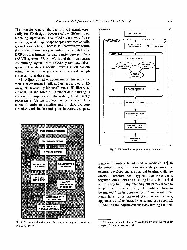
The approach to the application of VR techniques to plan a robot’s work on-site is an integral part of a comprehensive approach to automation of the con- struction process called computer integrated con- struction (CIC). It is described in numerous publica- tions, e.g. [33-361, and is presented schematically in Fig. 1. In CIC all the activities are carried out with the aid of computers, starting with design, through construction planning, to the actual on-site construc-
tion, including real-time control based on automated data acquisition. The construction on site is sup- ported with various construction management soft- ware tools and is performed by robots.
The long-term objective of this research is to develop a VR-based system for programming con- struction robots. It has three components (depicted in Fig. 2 as A, the approach; B, the VR environment and C, the V-MPIR module) - component C and parts of components A and B have already been developed. The first results are presented in Ap- pendix B and in http://www.strath.ac.uk/Depart- ments/Civeng/cm.html. An overview of the ap- proach is described below.
(1) Import design: once the facility’s detailed design is completed, it is entered into the system using the data exchange interface or regenerated using VRT’s (Virtual Reality Toolkit of Superscape) editor and library. The current system prototype allows DXF (AutoCAD’s Drawing Exchange For- mat) drawing files to be imported into the VR toolkit.
R. Nauon, A. Retik/Automation in Construction 5 (1997) 393-406 399
This transfer requires the user’s involvement, espe- cially for 3D designs, because of the different data modeling approaches (AutoCAD uses wire-frame modeling, while Superscape adopts constructive solid geometry modeling). ‘There is still controversy within
the research community regarding the suitability of DXF or other formats for data transfer between CAD and VR systems [37,:38]. We found that transferring 2D building layouts from a CAD system and subse- quent 3D models generation within a VR system using the layouts as guidelines is a good enough
compromise at this stage. (2) Adjust virtual environment: at this stage the
virtual environment is adjusted or regenerated in 3D using 2D layout “guidelines” and a 3D library of elements. If and when a 3D model of a building is successfully imported into the system, it will usually represent a “design product” to be delivered to a client. In order to visualize and simulate the con- struction work implementing the imported design as
Fig. 2. VR-based robot programming concept.
a model, it needs to be adjusted, or modified 1171. In the present case, the robot starts its job once the
external envelope and the internal bearing walls are erected. Therefore, for a typical floor these walls, together with a floor and a ceiling have to be marked as “already built” (by attaching attributes/labels to trigger a collision detection), the partitions have to be marked “under construction” 4 and some other items have to be removed (i.e. kitchen cabinets,
appliances, etc.) or located (i.e. temporary supports). In addition the adjustment includes turning the ceil-
Fig. 1. Schematic description of the computer integrated construc-
tion (CIC) process.
4 They will automatically be “already built” after the robot has
completed the construction task.
400 R. Nmon, A. Retik/Automation in Construction 5 (1997) 393-406
ings “transparent” in order to allow visual naviga- tion of the robot (shown in Appendix B). After the
model of the building is adjusted to the virtual environment, a robot and its operational interface are
selected from the VR library to carry out the tasks. At the time of writing, only one robot (V-MPIR) is available with an operational interface (Appendix B) allowing its navigation and manipulation. In addi- tion, virtual materials, palettes of blocks, etc. can be selected from another library and temporarily located within the building model.
(3) Plan robot tasks: at this stage the user has to determine the robot’s path by selecting workstations
and locating material pallets (in case of discrete material supply). This is done by navigating the robot visually, using a joystick or a 3D mouse. The
end-effector is activated by using the interface but- tons (Appendix B). The user is able to “be” either outside the picture (remote control or non-immersive navigation) or locate himself/herself on the robot and “drive-through” using head mounted display (HMD) (immersive navigation). In both cases, the planning is based on the user’s experience and is carried out by using a trial-and-error strategy. A collision detector, built into the system, simplifies
the robot navigation especially in the immersive mode. The possible application of a case-based ap- proach allowing adoption of previous solutions (in the form of existing programs) is under investigation.
(4) Simulate recorded sequence: once the user is satisfied with the plan, the sequence is recorded and played back to verify and refine the sequence and pallet locations. The simulation can be stopped at any point to allow the user to change a viewpoint or, in future development, to activate performance of a particular task (e.g. sensors) interactively.
(5) Estimate cost-time: the execution time of the finalized version of the robot path can now be calculated. This module is not implemented yet, it will either require knowledge of the robot productiv- ity, based on prior experience, e.g. [32,39], and/or will operate according to the same principles of graphic simulators. The quantity of work at every workstation will be derived from the project/build- ing model automatically [36]. The cost can then be calculated taking into account auxiliary tasks as well [39]. Then, if required, the results can be compared with other alternatives. The user can go back to step
3 and change the plan in an attempt to improve the performance.
(6) Generate program code: this module will gen- erate the robot’s movements, the geometry of the building and the location of the raw materials in the VRT built-in language - a program interface.
(7) Translate to a robot native language: the VRT code can then be translated, by another program, to the robot’s native language (MPIR’s in this case) and sent to the construction site to be transferred to the physical robot.
The proposed approach, once fully implemented, will facilitate planning of robot tasks, shorten robot- teaching time and improve its performance, thus making robotics more cost effective.
5. Experience in VR-based robot programming
An experiment to validate the prototype, evaluate the user interface and compare immersive and non- immersive ways of robot task planning using VR was conducted. This section describes the experi- ment and analyzes its results.
5.1. The experiment
The V-MPIR prototype has been developed to operate in two modes: immersive (using virtual I/O HMD with head trucker and joystick) and non-im- mersive (using a special operational interface, de- scribed above and presented in Appendix B, and a joystick). A collision detector is available in both cases. In order to assess and compare both ways, the experiment, involving 18 participants, was carried out in the VR lab of Strathclyde’s VCSRG (Virtual Construction Simulation Research Group) as follows.
5.1.1. The scope of the experiment Two groups of nine participants were each asked
to carry out individually two tasks. The tasks were to plan a robot path for a given design, as follows: - Task 1: planning of the robot path using immer-
sive VR technology - workstation 1. - Task 2: planning of the robot path using non-im-
mersive VR technology - workstation 2.
R. Nauon, A. Retik/Automation in Construction 5 (1997) 393-406 401
VR EXPERIENCE ROBOTICS EXPERKNCE
COMPUTER EXPERIENCE
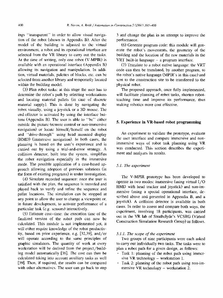
Fig. 3. The participants’ experience.
The participants ‘were asked to plan a path from outside the building to a work position within room number one (the first room on the right in Appendix B). They were advised that the main purpose was to plan a “good enough” robot path. They were also
told that although their performance would be mea-
sured, there was no time pressure.
.
5.1.2. Procedure For each workstation the participants did the fol-
lowing activities: . received the guidelines from the instructors;
performed the task at their own pace in order to get used to the environment and the equipment; informed the instructors when they were ready to perform the lab task. Each participant started only when the instructor had given the go-ahead signal and let the instructor know when he/she had finished. The performance time was recorded by
the instructor; each participant was asked to fill in a question- naire (Appendix C). The questionnaire provided
information on the background and experience of the participants, as well as comments or sugges- tions.
160 T
NON-IMMER!SIW
20 -- 0771 i
1 2 3 4 5 6 7 8 9 10 11 12 13 14 15 16 17 18
Participant Number
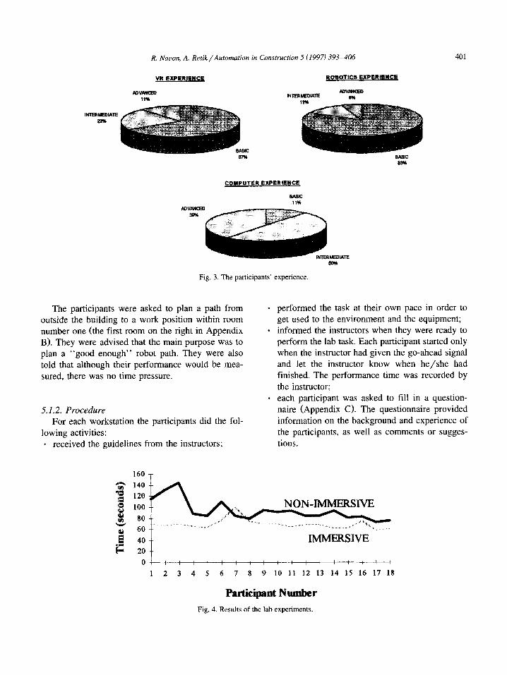
Fig. 4. Results of the lab experiments
402 R. Nauon, A. Retik/Automation in Construction 5 (1997) 393-406
NEITHER 6%
NON-IMMERSIVE
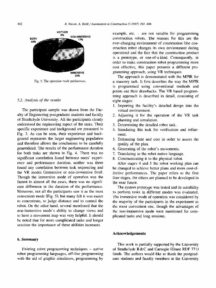
Fig. 5. The operation mode preferences.
5.2. Analysis of the results
The participant sample was drawn from the Fac- ulty of Engineering postgraduate students and faculty of Strathclyde University. All the participants clearly understood the engineering aspect of the tasks. Their specific experience and background are presented in Fig. 3. As can be seen, their experience and back- ground represents the larger engineering population and therefore allows the conclusions to be carefully
generalized. The results of the performance duration for both tasks are shown in Fig. 4. There was no significant correlation found between users’ experi-
ence and performance duration, neither was there found any correlation between task sequencing and the VR modes (immersive or non-immersive first). Though the immersive mode of operation was the fastest in almost all the cases, there was no signifi- cant difference in the duration of the performance. Moreover, not all the participants saw it as the most convenient mode (Fig. 5), but many felt it was easier to concentrate, to judge distance and to control the robot. On the other hand, several mentioned that the non-immersive mode’s ability to change views and to have a movement map was very helpful. It should
be noted that for more complicated tasks and longer sessions the importance of these abilities increases.
example, etc. - are not suitable for programming
construction robots. The reasons for this are the ever-changing environment of construction (the con- struction robot changes its own environment during operation) and the fact that the construction product is a prototype, or one-of-a-kind. Consequently, in order to make construction robot programming more cost effective, this paper presents a different pro- gramming approach, using VR techniques.
The approach is demonstrated with the MPIR for a masonry task. It first describes the way the MPIR is programmed using conventional methods and points out their drawbacks. The VR-based program-
ming approach is described in detail, consisting of eight stages: 1.
2.
3. 4.
5.
6.
7. 8.
Importing the facility’s detailed design into the virtual environment. Adjusting it for the operation of the VR task planning and simulation.
Determining the detailed robot task. Simulating this task for verification and refine- ment. Estimating time and cost in order to assess the quality of the plan.
Generating of the robot’s movements. Translating to the robot native language.
Communicating it to the physical robot. After stages 4 and 5 the robot working plan can
be changed to achieve better plans and more cost-ef- fective performances. The paper refers to the first four stages, the others are planned to be developed in the near future.
The system prototype was tested and its suitability to perform tasks in different modes was evaluated. The immersive mode of operation was considered by the majority of the participants in the experiment as the most convenient one, though the advantages of
the non-immersive mode were mentioned for com- plicated tasks and long sessions.
Acknowledgements
6. Summary
Existing robot programming techniques - native robot programming languages, off-line programming with the aid of graphic simulators, programming by
This work is partially supported by the University of Strathclyde R&C and Carnegie (Grant RDF 77 1) funds. The authors would like to thank the postgrad- uate students and faculty members at the University
R. Nauon, A. Retik/Automation in Construction 5 (19971 393-406 403
of Strathclyde for their participation in the VR lab next block in the palette (7) and the theoretical
experiment, as well as to acknowledge the help of location of the next block in the wall (8). The
Douglas Gourlay in programming the V-MPIR, and locations are theoretical because they cannot take
of Edward Coutts and Helen McGregor for making into account the tolerances in the block measure-
the lab preparations. ments.
Appendix A. Pseudocode of the masonry program
10 11 12 I3
14 15 16 17
18 19 20 21 22 23 25
calculate wall orientation (WO) calculate floor orientation (FO)
calculate the number of rows (m) calculate the number of bricks in each row (n)
for 1 to m for 1 to n
calculate next-block-p calculate next_block_w approach dist from next-block-p face FO fast
flip-up move next__block_p slow
delay 0.5 set suction = on depart dist from next-block-p slow flip-down move inter face WO fast approach d.ist from next_block_w fast
read next_block_w move next_block_w slow delay 0.5 s#ec suction = off depart dist from next_block_w slow
end end
The program is parametric and requires a prelimi- nary calculation of the orientation of the wall (1) 5 and of the floor (2): as well as the number of rows composing the wall (3) and the number of blocks in each row (4). At each cycle (7-23) a block is taken from the palette and laid in the wall. The cycle starts with a calculation olf the theoretical location of the
’ The numbers in brackets refer to the line number of the V-MPIR’s operational interface and screen shots
program. of an interactive planning session.
Next the robot moves the (vacuum) gripper (the tool) to the vicinity (a distance of “dist”, which is a constant number - about 1Ocm in the original pro- gram) of the next block in the palette in the right orientation (face FO) in a fast motion. The elbow of the robot’s arm is moved up (10) to assure that it
will not collide with the blocks in the palette. The robot is now in a position ready to approach
the next block in the palette, but the actual location
of the block is not known, therefore an input from a sensor is required (11) to receive this data. The way
the actual location is achieved depends on the type of sensor, a discussion of which exceeds the scope of this paper. When the exact location and orientation of the block are known, the robot can move the gripper to pick it up (12). This must be a fine motion to ensure accuracy. Before turning the suction on (14), a small delay is needed for the arm’s vibration, resulting from the motion, to relax (13). Once the block is attached to the gripper, it can be moved towards its designated location in the wall, which is
done in four stages. First the block is moved out a small distance away (15) in a fine well-controlled motion to ensure that it does not collide with neigh- boring blocks and the elbow is moved to its previous position (16) to avoid collision with the ceiling. In the second stage the block is moved to an intermedi- ate location (17) already in the orientation needed for its placement in the wall. The intermediate point is
needed to ensure a collision-free path to the block’s designated location in the wall. In the third stage the block is moved to the position where the actual location is measured (18, 19), after which the block is placed (20). A similar method to the one used for gently taking the block from the palette is used for releasing it and moving away from the wall (2 l-23).
Appendix B
404 R. Nacon, A. Retik/ Automation in Construction 5 (1997) 393-406
R. Navon, A. Retik/Automarion in Construction 5 (1997) 393-406 405
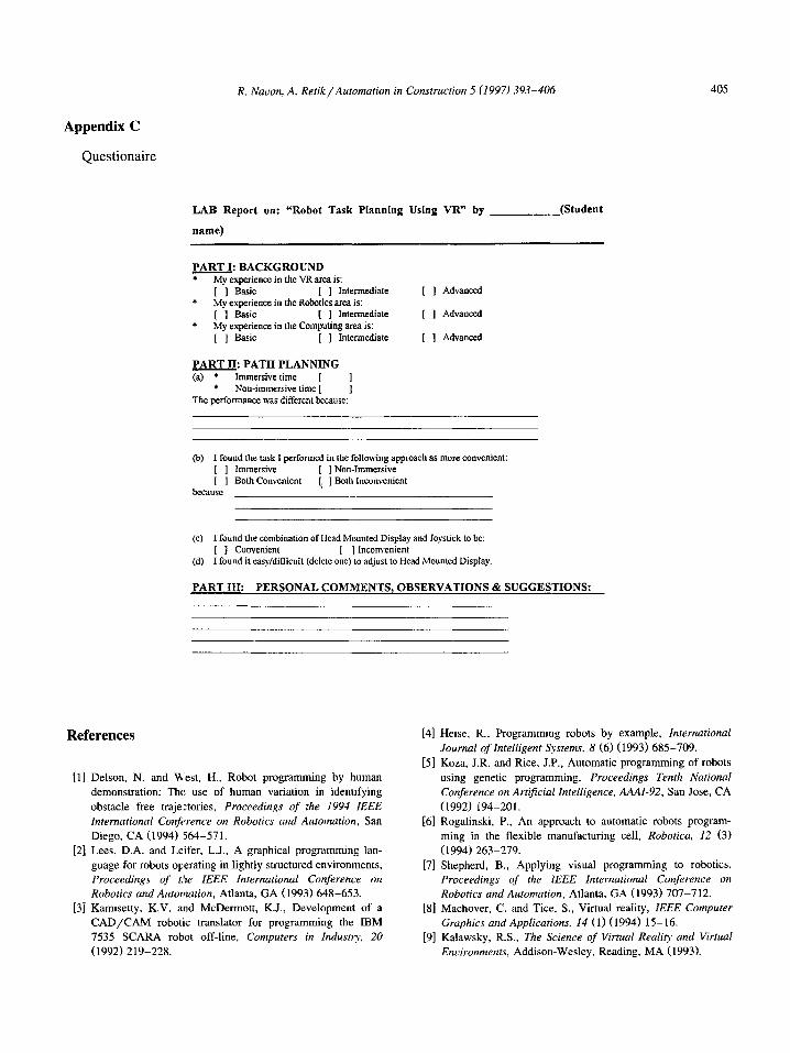
Appendix C
Questionaire
LAB Report on: “Robot Task Planning Using VR” by (Student
name)
PART I- BACKGROUND -- l Mv excerience in the VR area is: + [ -1 &sic [ ] Intermediate
My experience in the Robotics area is:
* [ 1 Basic [ ] Intermediate
My experience in the Computing area is: [ ] Basic [ ] Inlennediate
[ ] Advanced
[ 1 Advanced
[ ] Advanced
PART II- PATH PLANNING - (a) * Immersive time [
* Non-immersive time [ The performance ws different because:
@) I found the task I performed in the following approach as more convenient: [ ] Immersive [ ] Non-Immersive [ ] Both Convenient
because [: ] Both Inconvcnicnt
(c) I found the combination of Head Mounted Display and Joystick to bc: [ ] Convenient [ ] Inconvenient
(d) I found it easy/diflicoit (delctc one) to adjust to Head Mounted Display.
PART TIT: PERSONAL COMMENTS, OBSERVATIONS & SUGGESTIONS:
References
[l] Delson, N. and West, H., Robot programming by human
demonstration: The use of human variation in identifying
obstacle free trajelctories, Proceedings of the I994 ZEEE International Conjizrence on Roborics and Auromation, San
Diego, CA (1994) 564-571.
[2] Lees, D.A. and Leifer, L.J., A graphical programming lan-
guage for robots operating in lightly structured environments,
Proceedings of t,he IEEE Znternarional Conference on Robotics and Automation, Atlanta, GA (1993) 648-653.
[3] Kamisetty, K.V. and McDermott, K.J., Development of a
CAD/CAM robotic translator for programming the IBM
7535 SCARA robot off-line, Computers in Zndustv, 20 (1992) 219-228.
[4] Heise, R., Programming robots by example, Infernational Journal of Intelligent Systems, 8 (6) (1993) 685-709.
[5] Koza, J.R. and Rice, J.P., Automatic programming of robots
using genetic programming, Proceedings Tenth National Conference on Arrificial Intelligence, AAAZ-92, San Jose, CA
(1992) 194-201. [6] Rogalinski, P., An approach to automatic robots program-
ming in the flexible manufacturing cell, Robotica, 12 (3) (1994) 263-279.
[7] Shepherd, B., Applying visual programming to robotics, Proceedings of the IEEE Inrernarional Conference on Robotics and Automation, Atlanta, GA (1993) 707-712.
[8] Machover, C. and Tice, S., Virtual reality, IEEE Compurer Graphics and Applications, 14 (1) (1994) 15-16.
[9] Kalawsky, R.S., The Science of Virtual Real@ and Virtual Environments, Addison-Wesley, Reading, MA (1993).
406 R. Navon, A. Retik/Automation in Construction 5 (1997) 393-406
[lo] Sherman, B. and Judkins, P., Glimpses of Heaven, Visions of [25] Coiffet, P., Virtual reality systems - a new technique deeply Hell: Virtual Reality and its implications, Coronet Books, involving robot behavior, Proceedings of the 3rd French-
Hodder and Stoughton, Reading, Berks. and London PA Israeli Symposium on Robotics, Tel Aviv, Israel (1995) (1993). 7-16.
[ll] Vince, J., Virtual Reality Systems, Addison-Wesley, Reading,
MA (1995).
[12] Warwick, K., Gray, J. and Roberts, D. (eds.), Virtual Reality
in Engineering, The Institution of Electrical Engineers, Lon-
don (19931.
[26] Pimentel, K. and Teixeira, K., Virtual Reality Through the
New Looking Glass, 2nd edn., McGraw-Hill, New York
(1995).
[13] Larijani, C.L., The Virtual Reality Primer, McGraw-Hill,
New York (1994).
[14] Pimentel, K. and Teixeira, K., Virtual Reality Through the
New Looking Glass, 2nd edn., McGraw-Hill, New York
(1995).
[27] Kim, W., Graphical operator interface for space telephonics,
Proceedings of the IEEE International Conference on
Robotics and Automation, Atlanta, GA (1993) 761-768.
[28] Salisbury, J. and Srinivasan, M., Virtual environment tech-
nology for training, BBN Report No. 7661, VETREE, MIT,
Cambridge, MA (1992).
[15] Retik, A., Visualization for decision making in construction
planning, in: J.J. Connor et al., eds., Visualization and Intelli-
gent Design Systems in Engineering and Architecture,
CMP/Elsevier, Boston, MA (1993) 587-599.
[16] Retik, A., VR system prototype for visual simulation of the
construction process, in: A. Powell, ed., VR and Rapid
Protoryping in Engineering, EPSRC, Salford, UK (1995)
90-93.
[29] Fraisse, P., Pierrot, F. and Dauchez, P., Virtual environment
for robot force control, Proceedings of IEEE International
Conference on Robotics and Automation, Atlanta, GA (1993)
219-224.
[30] Burdea, G. and Coiffet, P., Virtual Reality Technology, Wi-
ley, Chichester, UK (1994).
[17] Retik, A., Discussion on geometric-based reasoning system
for project planning, Journal of Computing in Cioil Engi-
neering - ASCE, 9 (4) (1995) 293-294.
[18] Bridgewater, C., Griffin, M. and Retik, A., A use of virtual
reality in scheduling and design of construction projects,
Proceedings of the 11th International Symposium on Au-
tomation and Robotics in Construction, Brighton, UK (1994)
249-256.
[19] Hendrickson, C. and Rehak, D., Potential of a virtual con-
struction site for automation planning and analysis, Proceed-
ings of the 10th International Symposium on Automation and
Robotics in Construction, Houston, TX (1993) 511-518.
[20] Retik, A. and Hay, R., Visual simulation using VR, 10th
ARCOM Conference, Loughborough, UK (1994) 537-546.
[21] Ribarsky, W., Bolter, J., den Bosch, A.O. and Van Teylin-
den, R., Visualisation and analysis using virtual reality, IEEE
Computer Graphics and Applications, 14 (1) (1994) 10-12.
[22] Stone, R.J., Virtual reality in the services of transport, civil
engineering and construction, SERC Conference, London,
UK (1993) 327-336.
[31] Strommel, W.J., Neugebauer, J. and Flaig, T., Transputer
based reality workstation as implemented for the example of
industrial robot control, Proceedings of Interface to Real and
Virtual Worlds, Montpellier, France (1993) 137- 146.
[32] Warszawski, A. and Navon, R., Robot for interior finishing
works, Journal of Construction Engineering and Manage-
ment - ASCE 117 (3) (1991) 402-422.
[33] Yamazaki, Y., Integrated design and construction planning
system for computer integrated construction, Automation in
Construction, I (11 (1992) 21-26.
[34] Retik, A. and Warszawski, A., Automated design of prefabri-
cated building, Building and Environment, 29 (4) (1994)
421-436.
[35] Navon, R., COCSY I: CAM oriented CAD system, Journal
of Computing in Civil Engineering - ASCE, 9 (4) (1995)
236-243.
[36] Navon, R., COCSY II: CAD/CAM integration for on-site
robotics, Journal of Computing in Civil Engineering -
ASCE, (1995) (forthcoming).
[23] Wakefield, R. and O’Brien, J., A “virtual reality” type
simulation system for construction automation system devel-
opment, Proceedings of the 11th International Symposium on
Automation and Robotics in Construction, Brighton, UK
(1994) 239-248.
[24] Stone, R.J., Virtual reality and telepresence, Robotica, 10
(1992) 461-467.
[37] Alshawi, M. and Faraj, I., Integrating CAD and VR in
construction, in: A. Powel, ed., VR and Rapid Prototyping
for Engineering, EPSRC, Salford, UK (1995) 33.
[38] Griffin, M., Applications of virtual reality in architecture and
design, in: A. Powel, ed., VR and Rapid Prototyping for
Engineering, EPSRC, Salford, UK (1995) 73.
1391 Warszawski, A. and Rosenfeld, Y., Robot for interior finish-
ing works in building: Feasibility analysis, Journal of Con-
struction Engineering and Management - ASCE, 120 (1)
(1994) 132-151.
Recommended