United States Department of Agriculture
Forest Service
ForestProductsLaboratory
ResearchPaperFPL 471
Strength andStiffness of Light-FrameSloped Trusses Ronald W. Wolfe Donald H. Percival Russell C. Moody

Abstract Contents
Bending tests conducted on 42 wood trusses provided information on the effects of truss slope and lumber modulus of elasticity (MOE) on truss strength and stiffness. Two 28-foot-span Fink truss configurations with slopes of 3/12 and 6/12 were tested. Component lumber was all No. 2 grade southern pine separated into low, medium, and high MOE categories. All trusses exhibited linear load vs. deformation behavior up to and beyond twice their design load range. Variations in load carrying capacity were small within a slope/stiffness category, and lumber stiffness appeared to be closely correlated with load capacity, failure mode, and truss stiffness. Information in this report is an important first step toward formulating improved structural analysis procedures for roof systems.
Keywords: Roof, Trusses, Light-frame, Strength, Stiffness, Test, Truss plates
April 1986
Wolfe, Ronald W.; Percival, Donald H.; Moody, Russell C. Strength and stiffness of light-frame sloped trusses. Res. Pap. FPL 471. Madison, WI: U.S. Department of Agriculture, Forest Service, Forest Products Laboratory; 1986. 16 p.
A limited number of free copies of this publication are available to the public from the Forest Products Laboratory, One Gifford Pinchot Drive, Madison, WI 53705-2398. Laboratory publications are sent to over 1,000 libraries in the United States and elsewhere.
The Laboratory is maintained in cooperation with the University of Wisconsin.
PageIntroduction . . . . . . . . . . . . . . . . . . . . . . . . .
Literature Review . . . . . . . . . . . . . . . . . . . .
Objectives and Scope . . . . . . . . . . . . . . . . . . . . . . . . . . . .
Research Methods . . . . . . . . . . . . . . . . . . . . . . . . . . . . . . .Truss Design . . . . . . . . . . . . . . . . . . . . . . . . . . . . . . . . . .Material . . . . . . . . . . . . . . . . . . . . . . . . . . . . . . . . . . . . . . .Truss Fabrication . . . . . . . . . . . . . . . . . . . . . . . . . . . . . .TrussTests . . . . . . . . . . . . . . . . . . . . . . . . . . . . . . . . . . .Analysis Methods . . . . . . . . . . . . . . . . . . . . . . . . . . . . . .
Results . . . . . . . . . . . . . . . . . . . . . . . . . . . . . . . . . . . . . . . . .Lumber Properties . . . . . . . . . . . . . . . . . . . . . . . . . . . . .TrussStiffness . . . . . . . . . . . . . . . . . . . . . . . . . . . . . . . . .Truss Strength . . . . . . . . . . . . . . . . . . . . . . . . . . . . . . . . .
Analysis of Results . . . . . . . . . . . . . . . . . . . . . . . . . . . . . . .TrussStiffness . . . . . . . . . . . . . . . . . . . . . . . . . . . . . . . . .Truss Strength . . . . . . . . . . . . . . . . . . . . . . . . . . . . . . . . .
Conclusions . . . . . . . . . . . . . . . . . . . . . . . . . . . . . . . . . . . . .
Literature Cited . . . . . . . . . . . . . . . . . . . . . . . . . . . . . . . . . .
Appendix-Summary of Truss Member MOE Measurements . . . . . . . . . . . . . . . . . . . . . . . . . . . . . . . . . .
1
2
3
3 3 4 4 4 5
6 6 6 7
10 10 11
13
13
15

United States Department of Agriculture
Forest Service
ForestProductsLaboratory
Er ra t a
Strength and Stiffness of Light-Frame Sloped Trusses
Research Paper FPL 471 Errata
April 1986
In Figure 10, page 12. the uni t of measure for the ver t ical axis should be
not"Thousand lb"
"Thousands"
as wri t ten .
”"Mil l ion lb / in . 2 should be the unit of measure for the horizontal axis.
Wolfe, Ronald, W.; Percival, Donald H.; Moody, Russell C. Strength and Stiffness of Light-Frame Sloped Trusses. Res. Pap. FPL 471. Madison, WI: U.S. Department of Agriculture. Forest Service, Forest Products Laboratory; 1986. 16 p.

Strength and Stiffness of Light-FrameSloped Trusses1
Ronald W. Wolfe,* Research General Engineer Donald H. Percival,** Research Professor of Wood Technology Russell C. Moody,* Research General Engineer
*Forest Products Laboratory, Madison, WI **Small Homes Council, University of Illinois, Champaign, IL
Introduction
Roof systems used in residential construction have an outstanding record of structural performance. This is due in part to the use of conservative design assumptions. Current design procedures make no attempt to account for this conservatism; therefore, the inherent margin of safety in these roof systems cannot be quantified. This report covers the first phase of a research program to evaluate the relative reliabilities of various roof system designs. Specifically, the objective of this study is to characterize the strength and stiffness performance of two light-frame truss configurations.
Designers of steel and concrete structures have taken the lead in applying ‘reliability theory’ to structural design. They have published standards which improve design efficiency by taking into account variability of material as well as loads. The trend toward reliability-based design, evident for these materials, points the direction for improvements to engineered wood design. Most of the work required to characterize structural loads has already been done. The major concern of researchers dealing with reliability-based design of wood structures, therefore, is to characterize the probability distributions associated with structural capacity.
Another concept which should receive greater attention is system design. Current roof design procedures are based on single member design and give little credit to the advantage of repetitive member systems. In light-frame trussed roof systems, each truss is designed as though all its chord and web members have a near minimum clear wood strength and the maximum allowable strength reducing characteristic permitted for their grade. In addition, it is assumed that each truss in the system must be designed to carry its tributary area of design load. Limited recognition is given to load sharing mechanisms, either within the truss or between trusses. In order to improve roof system design, analysis methods must be developed to minimize unrecognized conservatism and provide a more accurate assessment of the true margin of safety. Methods are needed a) to accurately characterize the distribution of truss stiffness and strength, and b) to predict how loads are distributed among rafters within a roof system. This report presents individual truss test results which will be used to evaluate the accuracy of theoretical models developed to characterize roof system performance.
1This study was conducted in cooperation with the Southern Pine Inspection Bureau and the Truss Plate Institute.

Literature Review
Industry design standards for metal plate connected trusses were first presented by the Truss Plate Institute (TPI) in 1960. The approach was deterministic, connections were assumed to transfer only axial loads, and chord elements were analyzed as simple beams with superimposed moments.
Increased popularity of computers in the 1960’s resulted in significant improvements to truss design through the development of computer programs capable of providing indeterminate analyses. The most notable of these programs for the truss industry was the Purdue Plane Structures Analyzer (PPSA) (Suddarth 1972, Suddarth and Wolfe 1983). PPSA gave a more accurate analysis of member stresses than the TPI procedure, however, it was considered too costly to run and too complicated to use for everyday truss design. PPSA was therefore used by the truss industry as a means of checking and improving determinate analysis methods described in TPl’s design specifications (TPI 1978).
Other truss analysis programs have also been developed for the analysis of wood structures. A program called SADT, developed by Foschi (1977a & b), provides options to account for sheathing contributions and plastic behavior in truss plate connectors. This program permits characterization of displacement behavior beyond the design range whereas PPSA is a design tool, oriented to the analysis of trusses and frames within the elastic range.
The truss industry design methods have evolved following methods recommended in the National Design Specification for Wood Construction (NDS), (Nat. For. Prod. Assoc. 1982). The NDS recommends use of lumber stress values derived according to standards published by the American Society for Testing and Materials (ASTM) Standard D 245 (ASTM 1983c). These values are based on a clear wood strength (ASTM D2555-83), which is estimated to be at the 5th percentile of the distribution of all clear wood pieces. Strength reductions for grade characteristics assume knots and/or slope of grain are the maximum permitted. Thus each truss is designed as though each member is of minimum strength and quality for its species and grade.
Egerup (1975, 1979, undated) used Monte Carlo simulation, along with programs similar to those developed by Suddarth and Foschi, to assess the distribution of stiffness and load capacity of roof trusses. Results of his studies suggest that the 5th percentile value for truss load carrying capacity is greater than the load capacity predicted using the 5th percentile value for strength of individual members. He attributes this to several factors:
(a) loads are distributed away from weak members (b) there is a low probability that a member with the
5th percentile strength will be located at the point of maximum stress, and
(c) two or more members may show some form of plastic deformation before a truss actually fails.
Along with the development of computer models, data have also been collected on loads, member strength properties, and truss connector plate moment and axial load resistance. Thurmond et al. (1983) provided a summary of roof loads and derivation of distribution parameters. Truss lumber strength and stiffness properties have been collected (Gerhards and Percival 1979) and characterized (Hoyle et al. 1979) to indicate correlations between stiffness and strength. The In-grade test program being conducted as a cooperative effort between lumber grading agencies and the Forest Products Laboratory (FPL) is supplying full-size member strength and stiffness data for bending, tension and compression (Galligan et al 1980).
A number of studies have been conducted to characterize the load-slip behavior of several truss connector plates (Foschi 1979; Perkins et al. 1962; Quaile and Keenan 1979). Also, work conducted by Zahn (1982, 1984) at FPL, and by Buchanan at the University of British Columbia (Buchanan 1984) on the analysis of the effects of combined axial-bending loads provide a data base for the analysis of astress limit state for the chord and web members. Necessary material property information either is or soon will be available to begin development of a reliability-based design procedure for roof systems. Before these design procedures can be implemented, however, available material properties, analysis models, and load information must be refined and decisions must be made regarding limit state criteria.
2

Objectives and Scope Research Methods
The objective of this study is to characterize the strength and stiffness performance of two light-frame truss configurations. Results will be used in the development and evaluation of a truss strength/stiffness model. Undamaged trusses from this study will also be used in a subsequent study to evaluate the influence of system interactions on the load-deflection response of trusses used in a full-scale roof.
Forty-two full-size trusses were evaluated. Twenty-four were tested to failure and the other 18 were tested to 1.25 times their design load to determine their stiffness characteristics.
The two truss configurations considered were designed by representatives of the TPI. Prior to manufacturing the trusses, the lumber was sorted into three modulus of elasticity (MOE) categories. For each combination of truss configuration and MOE category, seven trusses were manufactured using metal plate connectors; three trusses were tested to 1.25 x design load and four trusses were tested to failure. A description of the truss test variables is given in table 1.
Truss Design
The truss configurations were selected to be typical of commonly used residential roof trusses. Both designs were for 28-foot-span Fink trusses to be spaced 24 inches on center. Both were designed for top chord load only. The 3/12 sloped truss (fig. 1) had a design live load of 17.5 Ib/ft2,and the 6/12 sloped truss had a design live load of 23 Ib/ft2.The dead load was 10 Ib/ft2 in each case. Total design loads for the 3/12 trusses (1,540 pounds), and for the 6/12 trusses (1,850 pounds), were for 10 years duration and were controlled by stresses in the top chord. The ratio of actual stress to allowable stress (sec. 303.6 of TPI 1978) at some location in the top chord of each truss design was equal to 1.0. The bottom chord had no vertical load, thus the ratio of actual to allowable was much lower (0.46 for the 3/12 and 0.20 for the 6/12).
In both cases, the metal plates were designed to be larger than normal (i.e. either thicker or larger area) to force failure to occur in the wood. The rationale for this “over plating” was that the allowable stresses for lumber include an adjustment for load duration and those for steel do not. A short-term test to determine truss strength would have agreater chance of resulting in metal failure than wood failure, if both were selected on the basis of the same ratio of imposed stress to allowable stress at the design load. Industry cooperators recommended that it was important to force failure to occur in the wood in order to supply data to evaluate the ability of a computer model to predict the probability of wood failure.
Table 1 .—Description of southern pine truss tests
Number of trusses
MOE 3/12 Slope 6/12 Slope Totalcategory Loaded to Loaded to Loaded to Loaded to1.25 x DL1
failure 1.25 x DL1failureonly only
Low (L) 3 4 3 4 14Medium (M) 3 4 3 4 14High (H) 3 4 3 4 14
TOTAL 9 12 9 12 421 DL = design load.
3

Figure 1.—Test trusses with 3/12 and 6/12 top chord slopes were designed for this study. In all cases, the heel and bottom chord splice joints were made using 16-gauge metal connector plates. Remaining plates were 20 gauge. Plate dimensions (in inches) are shown near each joint. (ML85 5612)
Material
The southern pine lumber used for this study was No. 2 2 x 4 in lengths of 12, 14, and 16 feet. Each piece was visually graded to meet the requirements for No. 2 and marked with an identification number. It was then passed through a Continuous Lumber Tester (CLT) machine to measure an average MOE value along its length. Additional evaluations of the lumber are discussed in Appendix A. Part of the lumber, obtained from Alabama, had MOE values ranging from 1.4 to 2.6 million lb/in2. A second portion, obtained from Arkansas, had MOE values ranging from 0.8 to 1.4 million lb/in2.
A 16-gauge metal truss plate supplied by one manufacturer was used at the heel and bottom chord splice joints, and a 20-gauge plate by another manufacturer was used at all other joints. In both cases, the teeth were approximately 3/8-in. long by 1/8-in. wide (3/8 in. by 5/32 in. for the 16 gauge, and 5/16 in. by 1/8 in. for the 20 gauge, see fig. 2).
Truss Fabrication
The lumber was divided into three MOE categories according to the average MOE values determined by the CLT machine. Lumber in the low stiffness (L) category had MOE values ranging from 0.8 to 1.4 million lb/in2. The range for the medium stiffness (M) was 1.4 to 2.0 million lb/in2,and for the high stiffness (H) was 2.0 to 2.6 million lb/in.2.The few pieces with MOE values outside of these ranges were not used.
Figure 2.—Truss plates used in the fabrication of the test trusses. The 16-gauge steel plate (top) had a tooth density of 4-1/2 teeth/in.2
and the 20-gauge steel plate (bottom) had a tooth density of 8 teeth/in.2. In both cases, the individual teeth are approximately 3/8-inch long by 1/8-inch wide. (ML85 5613)
Various lengths were randomly selected within each of the three MOE categories and assigned to 1 of 14 trusses (7 with 3/12 slope and 7 with 6/12 slope). Lumber for each truss was marked with a four part identification which gave the slope of the truss (3,6), its MOE category (L,M,H), a sequence number (1-7), and a code related to the location in the truss (fig. 3). Hydraulic presses were used to install the truss plates during manufacture. The trusses were then delivered to the testing laboratory where they were stored inside for at least 7 days prior to testing.
Truss Tests
The trusses were evaluated in a horizontal position using atest facility that consisted of parallel reaction brackets laid into a concrete floor (fig. 4). Hydraulic loading rams, lateral restraint braces, and reaction pads were attached to these brackets and could be moved in one direction in the plane of the floor to accommodate any truss configuration with a span of up to 35 feet and a height of up to 10 feet.
4

The ends of the truss were placed on 4-inch-wide reaction pads spaced 28 feet apart (outside to outside). Thus, the span from center-to-center of each reaction was 27 feet 8 inches. Twenty-eight concentrated loads were applied at 12-inch intervals along the top chord of each truss to simulate a uniform load application. These loads were applied using 14 hydraulic cylinders spaced 24 inches apart. Each cylinder was centered on a distributor beam which transferred the load to the top chord through two load points spaced 1 foot apart.
Deflection readings were taken using a taut wire stretched between points on the centroidal axis of the bottom chord above the reactions. Wood lath strips extending from seven points along the top chord held mirrored gauges under the wire to enable measurement of top chord deflections. Mirrored gauges were also placed at five points along the bottom chord. These positions are shown as the circled locations numbered 1-12 on figure 3.
Calibrated proving rings positioned at the reactions were used to measure the relationship between the hydraulic pump pressure gauge and the applied load on the truss. Two pilot trusses of each slope were tested to develop pressure versus load curves for the two truss configurations. These calibration procedures were also checked using electronic load cells. Measurements taken from the pressure versus load curves were found to be within 2 percent of those measured directly using the load cells. For the majority of tests, end grain Douglas-fir blocks were inserted at the reaction points and loads were read from the pressure gauge.
An initial load of 1,000 pounds was applied to each truss and held for 5 minutes to check for alignment, settlement, final adjustment, and then removed. Loads were then applied in increments of 0.25 x design load, and deflection readings were taken at each load increment after the load had been maintained for 5 minutes. Total time of test varied from about 1/2 hour for those tested to determine stiffness only to nearly 2 hours for the stronger trusses tested to failure.
For each combination of top chord slope and MOE category, three trusses were loaded to 1.25 x design load and four trusses were loaded to failure. For the trusses loaded to failure, deflection readings were taken at each increment until either failure appeared imminent or four times design load was reached. Ultimate load and failure locations were recorded for each truss along with comments regarding apparent influencing factors and failure progression.
Analysis Methods
Data obtained included lumber stiffness, and the stiffness, strength, and failure mode of each truss. Linear regression analyses were used to show how lumber MOE, truss slope, and load level affected truss response to increased load. Evaluations of the effect of lumber MOE on truss strength and failure mode were conducted to aid the prediction of truss failure. By correlating lumber and truss stiffness to
Figure 3.—Identification of truss members and deflection points. Truss members are identified by use and location: top chord (TC), bottom chord (SC), and web (WB). Member numbers are assigned left to right corresponding to the orientation of the truss in the test apparatus. Deflection points are circles and are also numbered left to right. (ML85 5614)
Figure 4.—Truss test facility at the Small Homes Council, University of Illinois, Champaign-Urbana with a 6/12 truss. (M85 0005)
strength and failure mode of those trusses tested to destruction, it was possible to estimate the load capacity of those trusses tested to only 1.25 x design. This information will be used in the planning stages of full-scale roof tests which will use the nondestructively tested trusses.

Results
Individual trusses will be referred to by their three-part Table 2.—Summary of modulus of elasticity values for lumber identification code number, as discussed previously under in each truss category truss fabrication. Truss members have an additional code 3/12 Slope 6/12 Slope related to their location in the truss (fig. 3).
category Average Coefficient Average CoefficientMOE
of ofIn all cases, the discussion of truss stiffness in the load MOE variation MOE variationrange from 0 to 1.25 x design load involves measurements
Million lb/in.2 Pct Million lb/in.2 Pcton all seven trusses in each slope-MOE category. Discussion of truss strength, however, refers only to the four Low (L) 1.23 9.4 1.24 9.2 trusses in each category which were tested to failure. Medium (M) 1.67 9.1 1.73 10.7
High (H) 2.30 6.7 2.31 7.2Lumber Properties
Table 2 gives a summary of MOE values measured for lumber used in the trusses in each slope/stiffness category. MOE values for each truss member are given in the Appendix.
Moisture content readings (resistance meter) taken at the time of testing indicated that all members of each truss had close to the same moisture content. Trusses 6H1 through 6H5 had moisture contents of 9 percent. All other trusses were at 10 percent.
Truss Stiffness
Within the range of design load, deflections appeared to be symmetric and linear with load. Figure 5 shows typical deflection profiles for a truss loaded to 1, 2, and 3 times design load. A parabolic curve connecting the panel point deflections is indicative of the global deflection of the truss, while deviations from this curve represent localized bending deflections in the loaded top chord. Significant localized bending deflection is evident in the top chord while all points on the bottom chord appeared to fit the expected parabolic pattern.
Figure 5.—Deflection profile of a low stiffness 3/12 sloped truss (3L7) loaded to 1, 2, and 3 times the design load of 1,540 lb. Loads were applied at l-foot intervals along the top chord, and deflections were measured at all web connections and midway between web connections for both top and bottom chords. (ML85 5615)
6
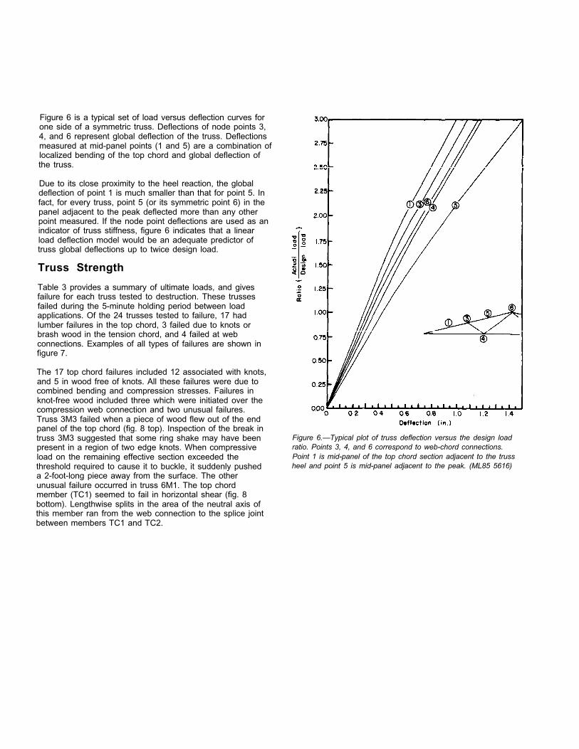
Figure 6 is a typical set of load versus deflection curves for one side of a symmetric truss. Deflections of node points 3, 4, and 6 represent global deflection of the truss. Deflections measured at mid-panel points (1 and 5) are a combination of localized bending of the top chord and global deflection of the truss.
Due to its close proximity to the heel reaction, the global deflection of point 1 is much smaller than that for point 5. In fact, for every truss, point 5 (or its symmetric point 6) in the panel adjacent to the peak deflected more than any other point measured. If the node point deflections are used as an indicator of truss stiffness, figure 6 indicates that a linear load deflection model would be an adequate predictor of truss global deflections up to twice design load.
Truss Strength
Table 3 provides a summary of ultimate loads, and gives failure for each truss tested to destruction. These trusses failed during the 5-minute holding period between load applications. Of the 24 trusses tested to failure, 17 had lumber failures in the top chord, 3 failed due to knots or brash wood in the tension chord, and 4 failed at web connections. Examples of all types of failures are shown in figure 7.
The 17 top chord failures included 12 associated with knots, and 5 in wood free of knots. All these failures were due to combined bending and compression stresses. Failures in knot-free wood included three which were initiated over the compression web connection and two unusual failures. Truss 3M3 failed when a piece of wood flew out of the end panel of the top chord (fig. 8 top). Inspection of the break in truss 3M3 suggested that some ring shake may have been present in a region of two edge knots. When compressive load on the remaining effective section exceeded the threshold required to cause it to buckle, it suddenly pushed a 2-foot-long piece away from the surface. The other unusual failure occurred in truss 6M1. The top chord member (TC1) seemed to fail in horizontal shear (fig. 8 bottom). Lengthwise splits in the area of the neutral axis of this member ran from the web connection to the splice joint between members TC1 and TC2.
Figure 6.—Typical plot of truss deflection versus the design load ratio. Points 3, 4, and 6 correspond to web-chord connections. Point 1 is mid-panel of the top chord section adjacent to the truss heel and point 5 is mid-panel adjacent to the peak. (ML85 5616)

Table 3.—Ultimate load and description of failure
Truss Failedidentification Ultimate load Design load
member1ratio Description of failure
Lb
3/12 SLOPED TRUSSES
3L1 4,620 3.00 TC13L3 5,000 3.25 TC13L5 4,240 2.75 TC43L7 5,000 3.25 BC2
Average 4,720 3.06
3M1 6,540 4.25 BC13M3 5,780 3.75 TC43M5 6,540 4.25 TC13M7 7,320 4.75 TC4
Average 6,550 4.25
3H2 7,320 4.75 WB23H4 8,080 5.25 WB2, WB3 3H6 7,320 4.75 BC13H7 7,320 4.75 TC1
Average 7,510 4.88
6/12 SLOPED TRUSSES
6L2 6,010 3.25 TC16L3 6,010 3.25 TC16L5 6,470 3.50 TC26L7 6,010 3.25 TC1
Average 6,120 3.31
6M1 10,630 5.75 TC16M2 9,240 5.00 TC26M4 9,240 5.00 TC26M7 9,240 5.00 TC1
Average 9,590 5.19
6H1 11,090 6.00 WB3
6H2 7,390 4.00 WB3
6H6 8,780 4.75 TC1
6H7 9,240 5.00 TC4
Average 9,120 4.94
Edge knot Edge knots Edge knot Brash failure at edge of heel plate
Centerline knot Shake and edge knots Edge knots Splinter in clear wood
Peak plate connection Peak plate connection Edge knot Centerline knot
Brash failure over web connection Edge knot Edge knot Brash failure over web connection
Shear at top chord splice Edge knot Centerline knot Splinter over web connection
Wood failure in web bottom chord connection Wood failure in web bottom chord connection Centerline knot over web connec- tion Centerline knot over web connec- tion
‘Primary piece of lumber in the truss (fig. 3) involved in failure.

Figure 7.—Examples of different failure types. Top: Top chord failures resulting from combined bending and compressive stresses. Middle: Bottom
chord failures resulting from tensile stresses. Bottom: Connection failures in a bottom chord joint (left) and a peak joint (right). (M85 0003)
9

Analysis of Results
Figure 8.—Unusual failures showing a buckling type failure (top) and shear type failure (bottom) in top chord. (M85 0004)
The three tension chord failures occurred in the 3/12 slope trusses. Two of these were associated with knots, and one occurred in brash wood close to the heel joint (middle of fig. 7).
All four connection failures were in the high MOE trusses-two in each slope category (bottom of fig. 7). For the 3/12 trusses these failures occurred at the web-to-peak joint. In these cases, the peak plates were misplaced by as much as 5/8 inch resulting in reductions in the number of teeth connecting the plate to the web. Estimated reduction in plate holding capacity was 13 percent for truss 3H2 and 29 percent for 3H4. For the two 6/12 trusses it was the bottom chord-tension web connection that failed. In both these cases, a layer of wood as thick as the tooth length was torn out of the web member.
Table 2 gives the mean values and coefficient of variation of MOE values for the lumber in each truss category. There was little difference between the MOE of lumber used in the 3/12 and 6/12 trusses.
Truss Stiffness
Table 4 gives three values of the average global stiffness for trusses in each slope-MOE category. These values were derived by using a linear regression analysis to determine the slope of the load versus deflection curve of each truss up to a load of 1.25 times the design load. Within each category, these slopes were averaged for the top chord node points (3 and 10), the bottom chord node points (4 and 9), and the peaks (6) (fig. 3). For 3/12 trusses, it is evident that deflection increases slightly as you move toward the center of the truss. However, this is not the case for the 6/12 trusses. For these trusses, the average peak deflections were about the same as those of the top chord (nodes 3 and 10).
Table 4.—Truss stiffness represented by the average slope of the load deflection curves determined at the five web-to-chord connections1
MOE Top chord2 Bottom chord3 Peak4
category Average COV5 Average COV5 Average COVs
Lb/in. Pct Lb/in. Pct Lb/in. Pct
3/12 TRUSSES
Low 3,460 8.8 3,270 9.1 3,220 9.6Medium 5,030 6.9 4,570 6.2 4,670 8.4High 6,020 5.3 5,600 6.5 5,550 6.6
6/12 TRUSSES
Low 9,820 6.3 9,040 5.1 9,740 3.5M e d i u m 1 3 , 9 2 0 9.7 13,010 7.0 14,540 6.8High 18,690 9.4 17,820 8.0 18,740 9.11Values are based on averages of seven tests up to 1.25 times design load.
2Averages of points 3 and 10 shown in fig. 3.
3Averages of points 4 and 9 shown in fig. 3.
4Point 6 shown in fig. 3.
5Coefficient of variation.
10

The effects of lumber MOE on truss stiffness can be Table B.-Linear regression parameters for deflection of 3/12 evaluated by comparing values given in tables 2 and 4. sloped trusses. Values correspond to average web-chord Table 2 shows that the average lumber MOE increased connection deflections at three increments of design load
about 40 percent with each change in lumber MOE category (DL); (L-M and M-H). Table 4 shows that the 6/12 trusses exhibit
DEFLECTION = A (Design Load Ratio) + B
about a 40 percent stiffness increase for both steps in Load increment lumber MOE category. For the 3/12 trusses, the low to Truss 0 - D L D L - 2 x D L 2 x D L - 3 x D L medium step is also close to 40 percent: however, the No. medium to high step is closer to 20 percent. This reduction A B A B A B
in stiffness increment may be due to the higher member 3L1 0.454 -0.002 0.487 -0.036 1.004 -1.070 stresses that develop in the low sloped, high MOE lumber 3L3 0.471 0.007 0.545 -0.067 0.850 -0.677
trusses. These higher member stresses in turn place greater stress on the truss plate connections which may have caused significant slip in the truss joints. This slip could
3L53L7
Average
0.4620.4380.456
0.0050.0020.000
0.5480.5730.541
-0.081-0.134-0.085
0.5780.8250.814
-0.141-0.637-0.631
cause these trusses to have less apparent stiffness. Table 4also shows that the 6/12 trusses were about three times as
3M13M3
0.3180.334
0.0060.009
0.3360.366
-0.012-0.022
0.5070.523
-0.353-0.336
stiff as the 3/12 trusses. 3M5 0.292 0.001 0.308 -0.017 0.466 -0.3323M7 0.330 0.000 0.345 -0.008 0.437 -0.191
Linear regression techniques were also used to characterize Average 0.318 0.000 0.345 -0.026 0.483 -0.303the load deflection response of trusses beyond the design load. This analysis, which was based only on those trusses 3H2 0.262 0.004 0.229 0.038 0.349 -0.203
tested to failure, resulted in a trilinear curve to represent the 3H4 0.247 0.000 0.344 -0.097 0.303 -0.016
average performance of trusses in each category. Slopes 3H6 0.289 -0.002 0.293 -0.005 0.390 -0.2003H7 0.271 0.003 0.259 0.015 0.353 -0.173
were derived for three segments of a load vs. deflection Average 0.267 0.000 0.282 -0.015 0.349 -0.148curve which represents the average deflection measured at five truss node points (Points 3, 4, 6, 9, and 10, fig. 3). These segments were selected as multiples of design load (DL) beginning at zero and ending at 3 times design load. Table 6.—Linear regression parameters for deflection of 6/12 Tables 5 and 6 give the parameters derived to fit straight sloped trusses. Values correspond to average web-chord line segments to these load intervals. These parameters connection deflections at three increments of design load were averaged for each stiffness category to give the (DL); trilinear curves shown in figure 9. These regression DEFLECTION = A (Design Load Ratio) + B
parameters were derived to model deflection as a function of Load increment the design load ratio (applied load/design load). In order to Truss 0 - D L D L - 2 x D L 2 x D L - 3 x D L convert the slope (A) of the first segment (zero to design No. load) shown in tables 5 and 6 to a truss stiffness, one must A B A B A B
multiply the truss design load by 1/A. 6L2 0.178 -0.006 0.191 -0.019 0.222 -0.0826L3 0.183 -0.003 0.242 -0.061 0.345 -0.268
Truss Strength 6L56L7
0.1980.197
-0.0040.001
0.2590.263
-0.066-0.065
0.3680.404
-0.283-0.349
Lumber MOE had an effect on both the failure modes and Average 0.186 0.000 0.239 -0.053 0.335 -0.245
strength of the trusses. Most of the low and medium MOE trusses failed due to bending in the end panels of the top
6M16M2
0.1240.134
-0.0010.002
0.1210.141
0.002-0.006
0.1080.113
0.0280.050
chord which would be expected based on the truss design. 6M4 0.123 -0.002 0.137 -0.016 0.138 -0.018For the high MOE trusses, there was a mixed mode of 6M7 0.121 -0.004 0.170 -0.053 0.149 -0.010failure with half of them failing in the web-to-chord Average 0.124 0.000 0.142 -0.018 0.127 0.012connection.
6H1 0.110 -0.003 0.119 -0.013 0.112 0.002
The effect of lumber MOE on strength is shown in figure 10 which contains plots of the maximum load of each truss
6H26H6
0.1090.091
-0.002-0.005
0.1160.103
-0.009-0.017
0.1060.138
0.012-0.087
6H7 0.109 -0.002 0.116 -0.009 0.106 0.012versus the average MOE of its component lumber. Within Average 0.102 0.000 0.114 -0.012 0.115 -0.015most MOE-slope categories, the trusses show little strength variation. An exception is the high MOE 6/12 trusses. The highest and lowest strength trusses in this group were the first two tested, and some difficulties in setup and calibration of the equipment may have influenced the failure loads. Also, the two types of failures (both bending-compression and web-to-chord connection) may have contributed to the higher variability for this group.
11
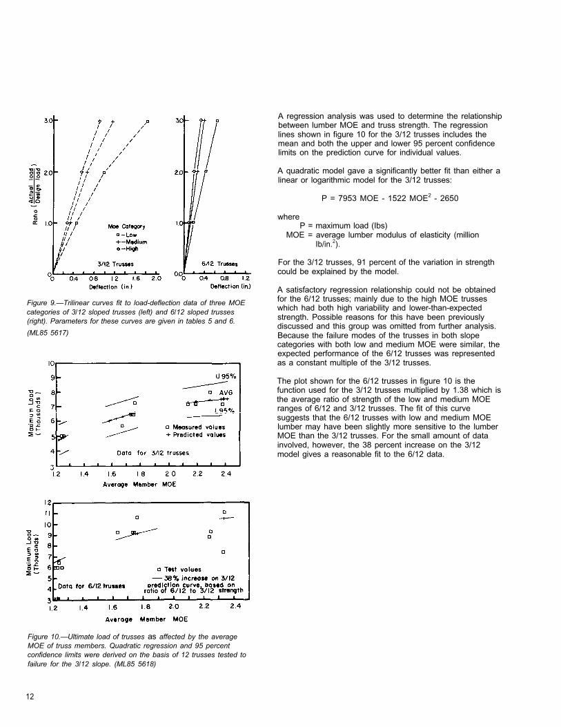
Figure 9.—Trilinear curves fit to load-deflection data of three MOE categories of 3/12 sloped trusses (left) and 6/12 sloped trusses (right). Parameters for these curves are given in tables 5 and 6.
(ML85 5617)
Figure 10.—Ultimate load of trusses as affected by the average MOE of truss members. Quadratic regression and 95 percent confidence limits were derived on the basis of 12 trusses tested to failure for the 3/12 slope. (ML85 5618)
A regression analysis was used to determine the relationship between lumber MOE and truss strength. The regression lines shown in figure 10 for the 3/12 trusses includes the mean and both the upper and lower 95 percent confidence limits on the prediction curve for individual values.
A quadratic model gave a significantly better fit than either alinear or logarithmic model for the 3/12 trusses:
P = 7953 MOE - 1522 MOE2 - 2650
whereP = maximum load (Ibs)
MOE = average lumber modulus of elasticity (million Ib/in.2).
For the 3/12 trusses, 91 percent of the variation in strength could be explained by the model.
A satisfactory regression relationship could not be obtained for the 6/12 trusses; mainly due to the high MOE trusses which had both high variability and lower-than-expected strength. Possible reasons for this have been previously discussed and this group was omitted from further analysis. Because the failure modes of the trusses in both slope categories with both low and medium MOE were similar, the expected performance of the 6/12 trusses was represented as a constant multiple of the 3/12 trusses.
The plot shown for the 6/12 trusses in figure 10 is the function used for the 3/12 trusses multiplied by 1.38 which is the average ratio of strength of the low and medium MOE ranges of 6/12 and 3/12 trusses. The fit of this curve suggests that the 6/12 trusses with low and medium MOE lumber may have been slightly more sensitive to the lumber MOE than the 3/12 trusses. For the small amount of data involved, however, the 38 percent increase on the 3/12 model gives a reasonable fit to the 6/12 data.
12

Conclusions Literature Cited
These test results demonstrate truss performance characteristics which will be useful in modeling the stiffness and strength of light-frame wood trusses to be used in tests to evaluate a full-scale roof system model. Specifically:
1. All trusses tested showed linear deflection performance up to twice the design load and only slight deviations from linearity up to three times design.
2. Test results show little variability in truss strength and stiffness within a given slope-MOE category.
3. There appears to be a definite correlation between lumber stiffness, load capacity, and failure mode for these trusses.
Caution should be used in applying these results to production trusses because:
1. All contained larger truss plates than required in order to force failure to occur in the wood member.
2. No loads were applied directly to the bottom chord as would be expected in most construction.
American Society for Testing and Materials. StandardMethod for Establishing Structural Grades and Related Allowable Properties for Visually Graded Lumber. ASTM D245-81. Philadelphia, PA: American Society for Testing and Materials; 1983.
American Society for Testing and Materials. StandardMethods for Establishing Clear Wood Strength Values. ASTM D2555-81. Philadelphia, PA: American Society for Testing and Materials; 1983.
Buchanan, A. H. Strength model and design methods for bending and axial load interaction in timber members. Vancouver, BC: University of British Columbia, Department of Civil Engineering; 1984. Ph. D. thesis.
Egerup, A. R. Monte Carlo simulation of the ultimate load of timber trusses. Structural Research Laboratory, Technical University of Denmark; undated.
Egerup, A. R. Theoretical and experimental determination of stiffness and ultimate load of timber trusses. Rep. R62. Structural Research Laboratory, Technical University of Denmark; 1975.
Egerup, A. R. European practice and future development in the design of metal plate connected wood trusses. In: Proceedings, Metal plate wood truss conference; Forest Products Research Society; 1979: 117-122.
Foschi, R. O. Analysis of wood diaphragms and trusses. Part I: Diaphragms. Canadian Journal of Civil Engineering. 4(3): 345-352; 1977a.
Foschi, R. O. Analysis of wood diaphragms and trusses. Part II: Truss plate connections. Canadian Journal of Civil Engineering. 4(3): 353-362; 1977b.
Foschi, R. O. Truss plate modeling in the analysis of trusses. in: Proceedings, Metal plate wood truss conference; Forest Products Research Society; 1979: 1557-1574.
Galligan, W. L.; Green, D. W.; Gromala, D. S.;Haskell, J. H. Evaluation of lumber properties in the United States and their application to structural research. Forest Products Journal. 30(16): 45-51; 1980.
Gerhards, C. C.; Percival, D. H. Species grades and mechanical properties of lumber sampled from truss fabricators. In: Proceedings, Metal plate wood truss conference; Forest Products Research Society; 1979. pp. 21-31.
Hoyle, R. J.; Haskell, J. H.; Galligan, W. L. Characterizing lumber properties for truss research. In: Proceedings, Metal plate wood truss conference; Forest Products Research Society; 1979. pp. 32-64.
National Forest Products Association. National design specification for wood construction. NFPA, 1619 Massachusetts Avenue, Washington, DC; 1982.
Perkins, R. H.; Suddarth, S. K.; Dale, A. C. Rotational resistance of three-membered nailed joints subjected to bending moment. Purdue University Research Bulletin No. 753, Lafayette, IN. 1962.
Quaile, A. T.; Keenan, F. J. Truss plate testing in Canada: Test procedures and factors affecting strength properties. In: Proceedings, Metal plate wood truss conference; Forest Products Research Society; 1979: 105-112.
13

Suddarth, S. K. A computerized wood engineering system: Purdue plane structures analyzer. Res. Pap. FPL 168. Madison, WI: U.S. Department of Agriculture, Forest Service, Forest Products Laboratory; 1972.
Suddarth, S. K.; Wolfe, R. W. Purdue plane structures analyzer II—A computerized wood engineering system. Gen. Tech. Rep. FPL-40. Madison, WI: U.S. Department of Agriculture, Forest Service, Forest Products Laboratory; 1983.
Thurmond, B. M.; Woeste, F. E.; Green D. W. Roofloads for reliability analysis of lumber properties data. Wood and Fiber Science. 16(2): 278-297; 1983.
Truss Plate Institute. Design specification for metal plate connected wood trusses. TPI 78. 1978 TPI, 583 D’Onofrio Drive, Suite 200, Madison, WI 53719.
Truss Plate institute. Design specification for metal plate connected parallel chord wood trusses. PCT 80, 1980 TPI, 583 D’Onofrio Drive, Suite 200, Madison, WI 53719.
Zahn, J. J. Strength of lumber under combined bending and compression. Res. Pap. FPL 391. Madison, WI: U.S. Department of Agriculture, Forest Service, Forest Products Laboratory; 1982.
Zahn, J. J. Strength of southern pine 2 x 4 beam columns. NTIS ADA 143-138; 1984.
14

Appendix Summary of Truss Member MOE Measurements
Two different values of MOE were obtained from the CLT machine for each piece of lumber. One was the average value which is an average of many short span values measured along the length. The other is called the “low point” which is the minimum value measured along the length. More details on span length and method of measuring are available from the equipment manufacturer.1
Prior to truss fabrication, a third value was measured for each piece using a flatwise bending test having a center point load on a 12-foot simple span. In the main text of this report, only the CLT average values were used. Tables Al and A2 give these values for each 3/12 and 6/12 truss member respectively.
Table A3 compares all three values of MOE for each of the MOE categories. This table includes more lumber than was used in manufacturing the trusses, thus the data may not agree with table 2.
Low point CLT values were about 3/4 of the average CLT values. For the high MOE lumber, the flatwise and CLT average values were quite close. But, for both the low and medium MOE lumber, the flatwise bending MOE was slightly less than the CLT average.
1lrvington-Moore, P.O. Box 23038, Portland, OR 97223.
Table A1 .—Modulus of elasticity for each truss member of the 3/12 trusses. These values were determined using a CLT ma-chine.
Truss TC1 TC2 TC3 TC4 BC1 BC2 WB1 WB2 WB3 WB4No.
LOWE3L1 0.97 1.31 1.33 1.23 1.37 1.26 1.09 1.21 1.23 1.09 3L2 1.30 1.23 1.32 1.26 1.31 1.25 1.32 1.14 1.14 1.11 3L3 1.06 1.03 1.29 1.34 1.17 1.11 1.32 1.34 1.39 1.32 3L4 0.96 1.33 1.39 1.27 1.01 1.35 1.11 1.37 1.34 1.09 3L5 1.24 1.24 1.29 0.97 1.39 1.19 1.29 1.03 1.24 1.11 3L6 1.13 1.32 1.37 1.33 1.23 1.34 1.32 1.25 1.25 1.11 3L7 1.37 1.33 1.33 1.13 1.33 1.15 1.09 1.31 1.21 1.28
MEDIUM E 3M1 1.76 1.69 1.72 1.85 1.55 1.79 1.83 1.89 1.57 1.83 3M2 1.63 1.56 1.89 1.47 1.49 1.41 1.58 1.58 1.58 1.58 3M3 1.60 1.65 1.72 1.87 1.80 1.63 1.52 1.85 1.52 1.52 3M4 1.55 1.74 1.74 1.87 1.59 1.49 1.55 1.54 1.61 1.55 3M5 1.77 1.65 1.69 1.60 1.75 1.93 1.55 1.89 1.90 1.55 3M6 1.46 1.75 1.29 1.42 1.91 1.92 1.52 1.57 1.52 1.52 3M7 1.71 1.56 1.90 1.74 1.81 1.81 1.75 1.54 1.85 1.88
HIGH E
Table A2.—Modulus of elasticity for each truss member of the 6/12 trusses. These values were determined using a CLT machine.
Truss TC1 TC2 TC3 TC4 BC1 BC2 WB1 WB2 WB3 WB4No.
LOW E
6L1 1.27 1.26 1.24 1.08 1.29 1.08 1.14 1.35 1.26 1.40 6L2 1.03 1.24 1.38 1.31 1.23 1.28 1.14 1.34 1.00 1.17 6L3 1.18 1.17 1.38 1.16 1.31 0.98 1.17 1.25 1.36 1.34 6L4 1.30 1.19 1.16 1.21 1.28 1.17 1.28 1.39 1.05 1.34 6L5 1.31 1.26 1.28 1.24 1.11 1.37 1.02 1.40 1.06 1.346L6 1.18 1.30 1.30 1.19 1.23 1.12 1.02 1.39 1.36 1.28 6L7 1.09 1.17 1.19 1.30 1.37 1.38 1.34 1.30 1.05 1.40
MEDIUM E
6M1 1.96 1.87 1.79 1.94 1.97 1.71 1.66 1.50 1.70 1.45 6M2 1.92 1.79 1.87 1.89 1.74 1.41 1.61 1.66 1.87 1.62 6M3 1.94 1.58 1.46 1.99 1.46 1.74 1.87 1.85 1.81 1.81 6M4 1.87 1.64 1.43 1.93 1.98 1.63 1.93 1.61 1.59 1.68 6M5 1.95 1.46 1.46 1.91 1.91 1.59 1.80 1.68 1.93 1.97 6M6 1.93 1.43 1.46 1.98 1.91 1.74 1.70 1.97 1.62 1.85 6M7 1.95 1.43 1.64 1.96 1.54 1.61 1.50 1.60 1.45 1.59
HIGH E 6H1 2.14 2.37 2.37 2.38 2.41 2.45 2.25 2.25 2.36 2.36 6H2 2.09 2.18 2.18 2.52 2.31 2.21 2.46 2.36 2.58 2.36 6H3 2.38 2.23 2.23 2.03 2.28 2.07 2.45 2.42 2.46 2.39 6H4 2.07 2.47 2.47 2.05 2.35 2.15 2.42 2.39 2.45 2.48 6H5 2.07 2.04 2.58 2.57 2.50 2.14 2.58 2.58 2.48 2.58 6H6 2.28 2.35 2.19 2.29 2.07 2.02 2.18 2.03 2.39 2.50 6H7 2.32 2.35 2.19 2.10 2.07 2.20 2.18 2.06 2.44 2.50
3H1 2.36 2.44 2.54 2.31 2.32 2.25 2.44 2.45 2.50 2.03 3H2 2.40 2.32 2.46 2.41 2.27 2.27 2.18 2.47 2.51 2.44 3H3 2.44 2.32 2.34 2.39 2.25 2.33 2.50 2.45 2.36 2.44 3H4 2.36 2.46 2.34 2.25 2.25 1.81 2.06 2.47 2.36 2.44 3H5 2.26 2.44 2.54 2.34 2.34 2.28 2.44 2.51 2.50 2.39 3H6 2.07 2.04 2.04 2.13 2.02 2.05 2.24 2.15 2.31 2.24 3H7 2.15 2.25 2.25 2.08 2.09 2.07 2.24 2.15 2.31 2.24
15

Table A3.—Comparison of measured MOE values for lumber used in the fabrication of the test trusses. CLT values were measured in the mill and flatwise bending values were measured just prior to truss fabrication.
MOE ApproximateContinuous lumber tester (CLT)
Flatwise bendingnumber of Average Low-point
STDSTD Mean COV2ERR 3
category specimens1
Mean COV2 STD Mean COV2ERR3ERR 3
Million Million Million Million Million Millionlb/in. 2 Pct lb/in. 2 lb/in. 2 Pct lb/in. 2 lb/in. 2 Pct lb/in. 2
Low 165 1.25 9.5 0.009 (4) (4) (4) 1.12 12 0.02Medium 150 1.74 10.6 0.015 1.26 16.3 0.017 1.65 14.3 0.019High 120 2.29 6.9 0.014 1.72 11.9 0.019 2.27 9.8 0.011Sample size for various methods of MOE measurement may vary by ±3.
2Coefficient of Variation for sample.
3Standard error of the estimate of mean value.
4Data not obtained on a significant part of the sample.
2.5-3/86
16
Recommended