TALAT Lectures 2710
Static Design Example
82 pages
Advanced Level
prepared during the TAS project:
TAS
Leonardo da Vinci Training in Aluminium Alloy Structural Design
Example developed with the “Mathcad” Software
Date of Issue: 1999 EAA - European Aluminium Association
TALAT 2710 2
2710 Static Design example Table of Contents (Active)
2710 Static Design example........................................................................................... 2 1. Introduction.......................................................................................................................6
2. Materials ............................................................................................................................7
3. Loads ..................................................................................................................................7
4. Load Combinations...........................................................................................................9
5. Loads Effects ...................................................................................................................11 5.1. Loads per unit length and concentrated loads...........................................................................11 5.2 Finite element calculations ........................................................................................................12 5.3. Section forces for characteristic loads ......................................................................................14 5.4. Design moments, shear forces and deflections .........................................................................16
6. Code Checking.................................................................................................................28 6.1 Column A ..................................................................................................................................28 6.2 Column B ..................................................................................................................................42 6.3 Column C ..................................................................................................................................55 6.4 Floor Beam D............................................................................................................................56 6.5 Roof Beam E .............................................................................................................................64 6.6 Roof Beam F .............................................................................................................................65 6.7 Welded Connections..................................................................................................................74
Table of Contents (Complete) 1 INTRODUCTION
1.1 Description 1.2 Sketches 1.3 References 1.4 S.I. units
2 MATERIALS 2.1 Aluminium 2.2 Other materials
3 LOADS 3.1 Permanent loads 3.2 Imposed loads 3.3 Environmental loads
3.3.1 Snow loads 3.3.2 Wind loads
TALAT 2710 3
4 LOAD COMBINATIONS 4.1 Ultimate limit state 4.2 Serviceability limit state
5 LOAD EFFECTS
5.1 Loads per unit length and concentrated loads 5.1.1 Permanent loads 5.1.2 Imposed loads, uniform distributed 5.1.3 Imposed loads, concentrated 5.1.4 Snow loads 5.1.5 Wind loads
5.2 Finite element calculations
5.2.0 Nodes and elements 5.2.1 Permanent loads 5.2.2 Imposed loads, uniformly distributed 5.2.3 Imposed loads, concentrated 5.2.4 Snow loads 5.2.4 Wind loads
5.3 Section forces for characteristic loads
5.3.1 Column A 5.3.2 Column B 5.3.3 Column C 5.3.4 Floor beam D 5.3.5 Floor beam E 5.3.5 Floor beam F
5.4 Design moments, shear forces and deflections
5.4.1 Column A 5.4.2 Column B 5.4.3 Column C 5.4.4 Floor beam D 5.4.5 Floor beam E 5.4.6 Floor beam F 5.4.7 Joint A-D 5.4.8 Joint B-D 5.4.9 Joint A-E 5.4.10 Joint B-E 5.4.11 Joint B-F 5.4.12 Joint F-C 5.4.13 Column base
TALAT 2710 4
6 CODE CHECKING 6.1 Column A
6.1.1 Dimensions and material properties 6.1.2 Internal moments and forces 6.1.3 Classification of the cross section in y-y-axis bending 6.1.4 Classification of the cross section in z-z-axis bending 6.1,5 Classification of the cross section in axial compression 6.1.6 Welds 6.1.7 Design resistance, y-y-axis bending 6.1.8 Design resistance, z-z-axis bending 6.1.9 Axial force resistance, y-y buckling 6.1.10 Axial force resistance, z-z axis buckling 6.1.11 Flexural buckling of beam-column 6.1.12 Lateral-torsional buckling between purlins 6.1.13 Design moment at column base 6.1.14 Deflections 6.1.15 Summary
6.2 Column B
6.2.1 Dimensions and material properties 6.2.2 Internal moments and forces 6.2.3 Classification of the cross section in y-y-axis bending 6.2.4 Classification of the cross section in z-z-axis bending 6.2,5 Classification of the cross section in axial compression 6.2.6 Welds 6.2.7 Design resistance, y-y-axis bending 6.2.8 Design resistance, z-z-axis bending 6.2.9 Axial force resistance, y-y buckling 6.2.10 Axial force resistance, z-z axis buckling 6.2.11 Flexural buckling of beam-column 6.2.12 Lateral-torsional buckling between purlins 6.2.13 Design moment at column base 6.2.14 Deflections 6.2.14 Summary
6.3 Column C
6.4 Floor Beam D
6.4.1 Dimensions and material properties 6.4.2 Internal moments and forces 6.4.3 Classification of the cross section 6.4.4 Welds 6.4.5 Bending moment resistance 6.4.6 Bending resistance in a section with holes 6.4.7 Shear force resistance 6.4.8 Deflections 6.4.8 Summary
TALAT 2710 5
6.5 Roof Beam E
6.6 Roof Beam F
6.6.1 Dimensions and material properties 6.6.2 Internal moments and forces 6.6.3 Classification of the cross section 6.6.4 Welds 6.6.5 Bending moment resistance 6.6.6 Lateral-torsional buckling between purlins 6.6.7 Bending resistance in a section with holes 6.6.8 Shear force resistance 6.6.9 Concentrated transverse force 6.6.10 Deflections 6.6.11 Summary
6.7 Welded connections
6.7.1 Weld properties 6.7.2 Longitudinal weld of floor beam D 6.7.3 Base of column B 6.7.4 Connection between floor beam D and column B
Software
The example is worked out using the MathCad software in which some symbols have special meaninaccording to the following
x 50.6 mm. Assign value
y 2.5 mm. Global assignment
x y 53.1 mm= Evaluate expression
a b Boolean equals
0.5 Decimal point
c 1 3 2( ) Vector
d 2 4 3( ) Vector
a c d.( ) Vectorize (multiply the elements in vector c with corresponding elements in d)
a 2 12 6( )= Result
Structure
The structure was proposed by Steinar Lundberg, who also contributed with valuable suggestions.Part 1 to 6.6 was worked out by Torsten Höglund and 6.7 by Myriam Bouet-Griffon.
TALAT 2710 6
1. Introduction
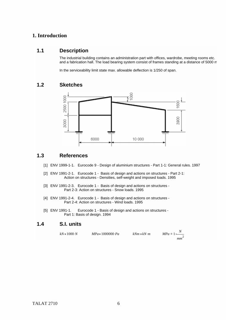
1.1 DescriptionThe industrial building contains an administration part with offices, wardrobe, meeting rooms etc. and a fabrication hall. The load bearing system consist of frames standing at a distance of 5000 m
In the serviceability limit state max. allowable deflection is 1/250 of span.
1.2 Sketches
1.3 References[1] ENV 1999-1-1. Eurocode 9 - Design of aluminium structures - Part 1-1: General rules. 1997
[2] ENV 1991-2-1. Eurocode 1 - Basis of design and actions on structures - Part 2-1: Action on structures - Densities, self-weight and imposed loads. 1995
[3] ENV 1991-2-3. Eurocode 1 - Basis of design and actions on structures - Part 2-3: Action on structures - Snow loads. 1995
[4] ENV 1991-2-4. Eurocode 1 - Basis of design and actions on structures - Part 2-4: Action on structures - Wind loads. 1995
[5] ENV 1991-1. Eurocode 1 - Basis of design and actions on structures - Part 1: Basis of design. 1994
1.4 S.I. unitskN 1000 N. MPa 1000000 Pa. kNm kN m. MPa 1
N
mm2=
TALAT 2710 7
2. Materials
3. Loads
2.1 Aluminium[1], 3.2.2 The extrusions are alloy EN AW-6082, temper T6
The plates are EN AW-5083 temper H24
Strength of aluminium alloys
EN AW-6082 T6EN AW-5083 H24
f o 260 MPa. f u 310 MPa.
f o 250 MPa. f u 340 MPa.
[1], 5.1.1 The partial safety factor for the members
The partial safety factor for welded connections
Design values of material coefficients
Modulus of elasticityShear modulusPoisson´s ratio
Coefficient of linear thermal expansion
Density
γ M1 1.10 γ M2 1.25
[1], 6.1.1 γ Mw 1.25
E 700000 MPa.G 27000 MPa.ν 0.3
α T 23 10 6.
ρ 2700 kg. m 3.
2.2 Other materialsComment: Properties of any other materials to be filled in
3.1 Permanent loads[3], ?? Permanent loads are self-weight of structure, insulation, surface materials and fixed equipment
Permanent load on roof
Permanent load on floor
q´ p.roof 0.5 kN. m 2.
q´ p.floor 0.7 kN. m 2.
3.2 Imposed loads[2], 6.3.1 Office area => Category B
q´ k.floor 3 kN. m 2.Uniform distributed load
Concentrated loadQ k.floor 2 kN.
[2], 6.3.4 Roofs not accessible except for normal maintenance etc. => Category H =>
Uniform distributed load
Concentrated load
q´ k.roof 0.75 kN. m 2.
Q k.roof 1.5 kN.
TALAT 2710 8
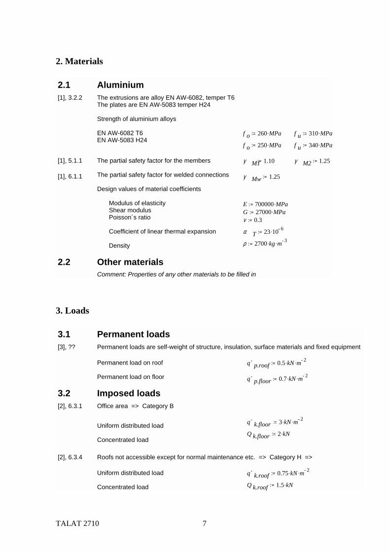
[?], ?? Load from crane, the crane located in the middle of the roof beam in the production hall
Concentrated load Q crane 50 kN.
3.3 Environmental loads
3.3.1 Snow loads[3] Comment: The characteristic values of the snow loads vary from nation to nation. For simplicity
for this design example, a snow load is chosen including shape coefficient, exposure coefficientand thermal coefficient. In a design report the calculation of the snow loads have to be shown.
Snow load q´ snow 2 kN m 2.
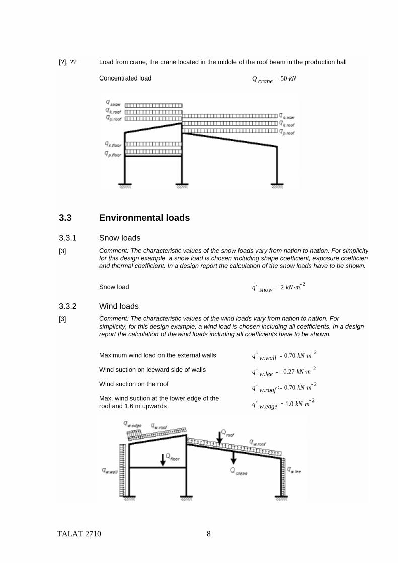
3.3.2 Wind loads[3] Comment: The characteristic values of the wind loads vary from nation to nation. For
simplicity, for this design example, a wind load is chosen including all coefficients. In a design report the calculation of the wind loads including all coefficients have to be shown.
Maximum wind load on the external walls
Wind suction on leeward side of walls
Wind suction on the roof
Max. wind suction at the lower edge of theroof and 1.6 m upwards
q´ w.wall 0.70 kN m 2.
q´ w.lee 0.27 kN m 2.
q´ w.roof 0.70 kN m 2.
q´ w.edge 1.0 kN m 2.
TALAT 2710 9
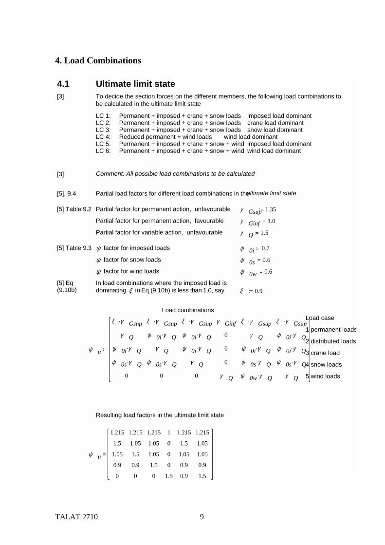
4. Load Combinations
4.1 Ultimate limit state[3] To decide the section forces on the different members, the following load combinations to
be calculated in the ultimate limit state.
LC 1: Permanent + imposed + crane + snow loads imposed load dominant LC 2: Permanent + imposed + crane + snow loads crane load dominantLC 3: Permanent + imposed + crane + snow loads snow load dominantLC 4: Reduced permanent + wind loads wind load dominantLC 5: Permanent + imposed + crane + snow + wind imposed load dominantLC 6: Permanent + imposed + crane + snow + wind wind load dominant
[3] Comment: All possible load combinations to be calculated
[5], 9.4 Partial load factors for different load combinations in the ultimate limit state
[5] Table 9.2 Partial factor for permanent action, unfavourable γ Gsup 1.35
Partial factor for permanent action, favourable γ Ginf 1.0
Partial factor for variable action, unfavourable γ Q 1.5
[5] Table 9.3 ψ factor for imposed loads ψ 0i 0.7
ψ factor for snow loads ψ 0s 0.6
ψ factor for wind loads ψ 0w 0.6
[5] Eq(9.10b)
In load combinations where the imposed load is dominating ξ in Eq (9.10b) is less than 1.0, say ξ 0.9
Load combinationsLoad case
1 permanent loads
2 distributed loadsψ u
ξ γ Gsup.
γ Q
ψ 0i γ Q.
ψ 0s γ Q.
0
ξ γ Gsup.
ψ 0i γ Q.
γ Q
ψ 0s γ Q.
0
ξ γ Gsup.
ψ 0i γ Q.
ψ 0i γ Q.
γ Q
0
γ Ginf
0
0
0
γ Q
ξ γ Gsup.
γ Q
ψ 0i γ Q.
ψ 0s γ Q.
ψ 0w γ Q.
ξ γ Gsup.
ψ 0i γ Q.
ψ 0i γ Q.
ψ 0s γ Q.
γ Q
3 crane load
4 snow loads
5 wind loads
Resulting load factors in the ultimate limit state
ψ u
1.215
1.5
1.05
0.9
0
1.215
1.05
1.5
0.9
0
1.215
1.05
1.05
1.5
0
1
0
0
0
1.5
1.215
1.5
1.05
0.9
0.9
1.215
1.05
1.05
0.9
1.5
=
TALAT 2710 10
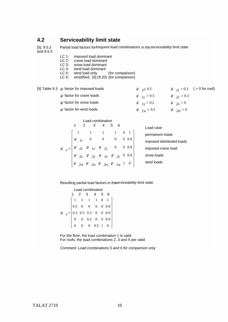
4.2 Serviceability limit state[5], 9.5.2and 9.5.5
Partial load factors for frequent load combinations in the serviceability limit state
LC 1: imposed load dominant LC 2: crane load dominantLC 3: snow load dominantLC 4: wind load dominantLC 5: wind load only (for comparison)LC 6: simplified, [5] (9.20) (for comparison)
[5] Table 9.3 ψ factor for imposed loads ψ 1i 0.5 ψ 2i 0.3 ( = 0 for roof)
ψ factor for crane loads ψ 1c 0.5 ψ 2c 0.3
ψ factor for snow loads ψ 1s 0.2 ψ 2s 0
ψ factor for wind loads ψ 1w 0.5 ψ 2w 0
Load combination1 2 3 4 5 6 Load case
permanent loads
imposed distributed loads
ψ s
1
ψ 1i
ψ 2c
ψ 2s
ψ 2w
1
0
ψ 1c
ψ 2s
ψ 2w
1
0
ψ 2c
ψ 1s
ψ 2w
1
0
0
ψ 2s
ψ 1w
0
0
0
0
1
1
0.9
0.9
0.9
0
imposed crane load
snow loads
wind loads
Resulting partial load factors in the serviceability limit state
Load combination1 2 3 4 5 6
ψ s
1
0.5
0.3
0
0
1
0
0.5
0
0
1
0
0.3
0.2
0
1
0
0
0
0.5
0
0
0
0
1
1
0.9
0.9
0.9
0
=
For the floor, the load combination 1 is validFor roofs, the load combinations 2, 3 and 4 are valid
Comment: Load combinations 5 and 6 for comparison only
TALAT 2710 11
5. Loads Effects
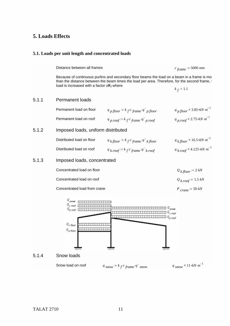
5.1. Loads per unit length and concentrated loads
Distance between all frames c frame 5000 mm.
Because of continuous purlins and secondary floor beams the load on a beam in a frame is mothan the distance between the beam times the load per area. Therefore, for the second frame, tload is increased with a factor of kf where
k f 1.1
5.1.1 Permanent loads
Permanent load on floor q p.floor k f c frame. q´ p.floor. q p.floor 3.85 kN m 1.=
Permanent load on roof q p.roof k f c frame. q´ p.roof. q p.roof 2.75 kN m 1.=
5.1.2 Imposed loads, uniform distributed
Distributed load on floor q k.floor k f c frame. q´ k.floor. q k.floor 16.5 kN m 1.=
Distributed load on roof q k.roof k f c frame. q´ k.roof. q k.roof 4.125 kN m 1.=
5.1.3 Imposed loads, concentrated
Concentrated load on floor Q k.floor 2 kN.
Concentrated load on roof Q k.roof 1.5 kN.
Concentrated load from crane P crane 50 kN.
5.1.4 Snow loads
Snow load on roof q snow k f c frame. q´ snow. q snow 11 kN m 1.=
TALAT 2710 12
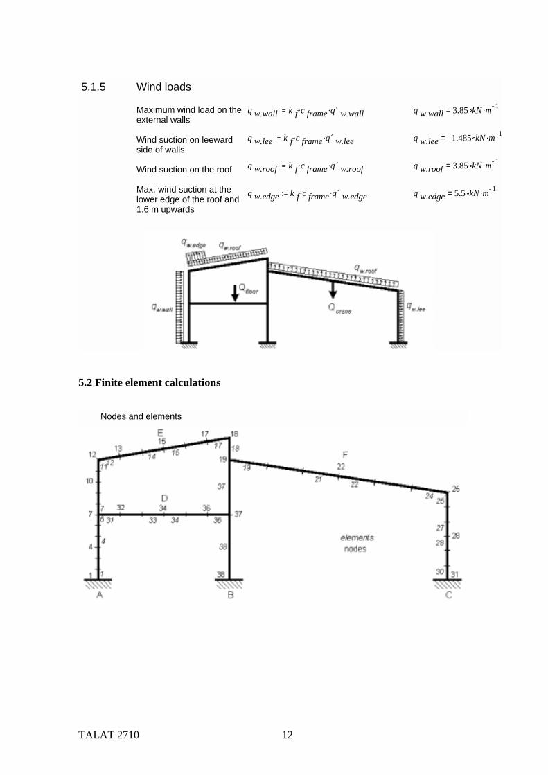
5.2 Finite element calculations
5.1.5 Wind loads
Maximum wind load on the external walls
Wind suction on leewardside of walls
Wind suction on the roof
Max. wind suction at thelower edge of the roof and1.6 m upwards
q w.wall k f c frame. q´ w.wall. q w.wall 3.85 kN m 1.=
q w.lee k f c frame. q´ w.lee. q w.lee 1.485 kN m 1.=
q w.roof k f c frame. q´ w.roof. q w.roof 3.85 kN m 1.=
q w.edge k f c frame. q´ w.edge. q w.edge 5.5 kN m 1.=
Nodes and elements
TALAT 2710 13
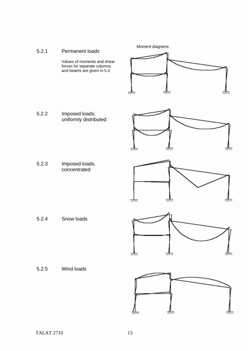
Moment diagrams5.2.1 Permanent loads
Values of moments and shear forces for separate columns and beams are given in 5.3
5.2.2 Imposed loads,uniformly distributed
5.2.3 Imposed loads, concentrated
5.2.4 Snow loads
5.2.5 Wind loads
TALAT 2710 14
5.3. Section forces for characteristic loads
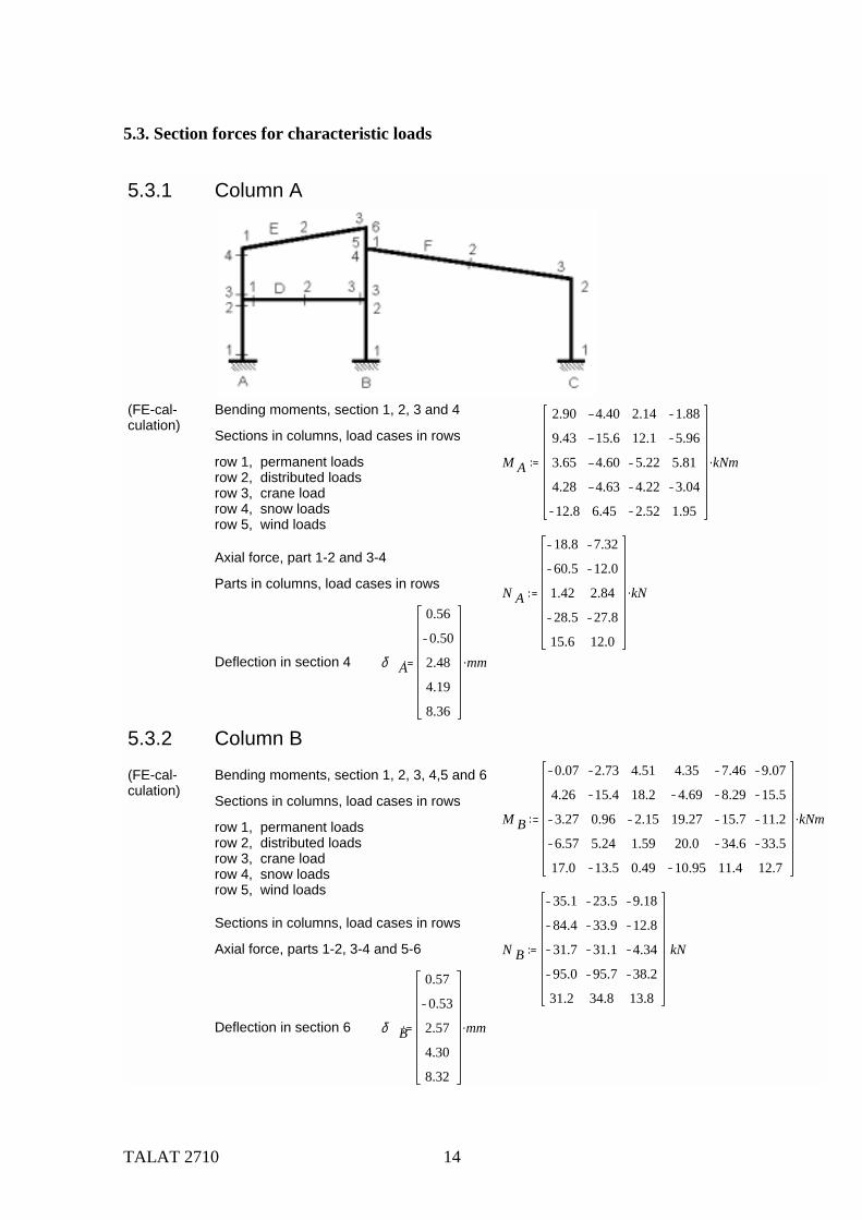
5.3.1 Column A
(FE-cal-culation)
Bending moments, section 1, 2, 3 and 4
Sections in columns, load cases in rows
row 1, permanent loadsrow 2, distributed loadsrow 3, crane loadrow 4, snow loadsrow 5, wind loads
M A
2.90
9.43
3.65
4.28
12.8
4.40
15.6
4.60
4.63
6.45
2.14
12.1
5.22
4.22
2.52
1.88
5.96
5.81
3.04
1.95
kNm.
Axial force, part 1-2 and 3-4
Parts in columns, load cases in rows N A
18.8
60.5
1.42
28.5
15.6
7.32
12.0
2.84
27.8
12.0
kN.
Deflection in section 4 δ A
0.56
0.50
2.48
4.19
8.36
mm.
5.3.2 Column B
(FE-cal-culation)
Bending moments, section 1, 2, 3, 4,5 and 6
Sections in columns, load cases in rowsM B
0.07
4.26
3.27
6.57
17.0
2.73
15.4
0.96
5.24
13.5
4.51
18.2
2.15
1.59
0.49
4.35
4.69
19.27
20.0
10.95
7.46
8.29
15.7
34.6
11.4
9.07
15.5
11.2
33.5
12.7
kNm.row 1, permanent loadsrow 2, distributed loadsrow 3, crane loadrow 4, snow loadsrow 5, wind loads
Sections in columns, load cases in rows
Axial force, parts 1-2, 3-4 and 5-6 N B
35.1
84.4
31.7
95.0
31.2
23.5
33.9
31.1
95.7
34.8
9.18
12.8
4.34
38.2
13.8
kN
Deflection in section 6 δ B
0.57
0.53
2.57
4.30
8.32
mm.
TALAT 2710 15
5.3.3 Column CComment: To reduce the extent of this example, this column is left out. It can be given, conservatively the same section as column B
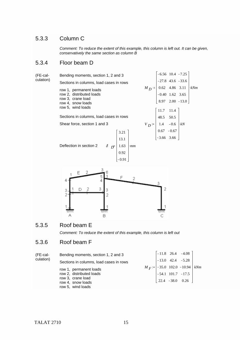
5.3.4 Floor beam D
(FE-cal-culation)
Bending moments, section 1, 2 and 3
Sections in columns, load cases in rowsM D
6.56
27.8
0.62
0.40
8.97
10.4
43.6
4.86
1.62
2.00
7.25
33.6
3.11
3.65
13.0
kNm.row 1, permanent loadsrow 2, distributed loadsrow 3, crane loadrow 4, snow loadsrow 5, wind loads
Sections in columns, load cases in rows
Shear force, section 1 and 3 V D
11.7
48.5
1.4
0.67
3.66
11.4
50.5
0.6
0.67
3.66
kN.
Deflection in section 2 δ D
3.21
13.1
1.63
0.92
0.91
mm.
5.3.5 Roof beam EComment: To reduce the extent of this example, this column is left out
5.3.6 Roof beam F
(FE-cal-culation)
Bending moments, section 1, 2 and 3
Sections in columns, load cases in rowsM F
11.8
13.0
35.0
54.1
22.4
26.4
42.4
102.0
101.7
38.0
4.08
5.28
10.94
17.5
0.26
kNmrow 1, permanent loadsrow 2, distributed loadsrow 3, crane loadrow 4, snow loadsrow 5, wind loads
TALAT 2710 16
5.4. Design moments, shear forces and deflections
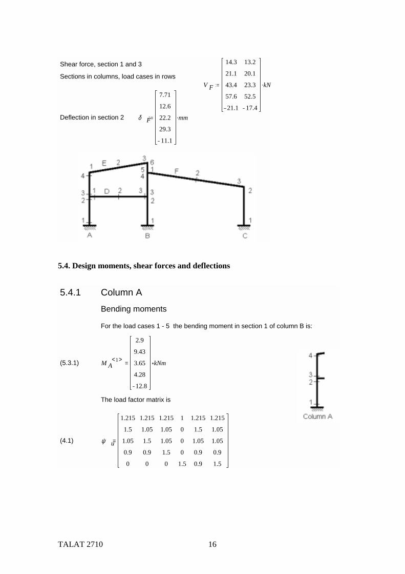
Shear force, section 1 and 3
Sections in columns, load cases in rowsV F
14.3
21.1
43.4
57.6
21.1
13.2
20.1
23.3
52.5
17.4
kN.
Deflection in section 2 δ F
7.71
12.6
22.2
29.3
11.1
mm.
5.4.1 Column A
Bending moments
For the load cases 1 - 5 the bending moment in section 1 of column B is:
(5.3.1) M A1< >
2.9
9.43
3.65
4.28
12.8
kNm=
The load factor matrix is
(4.1) ψ u
1.215
1.5
1.05
0.9
0
1.215
1.05
1.5
0.9
0
1.215
1.05
1.05
1.5
0
1
0
0
0
1.5
1.215
1.5
1.05
0.9
0.9
1.215
1.05
1.05
0.9
1.5
=
TALAT 2710 17
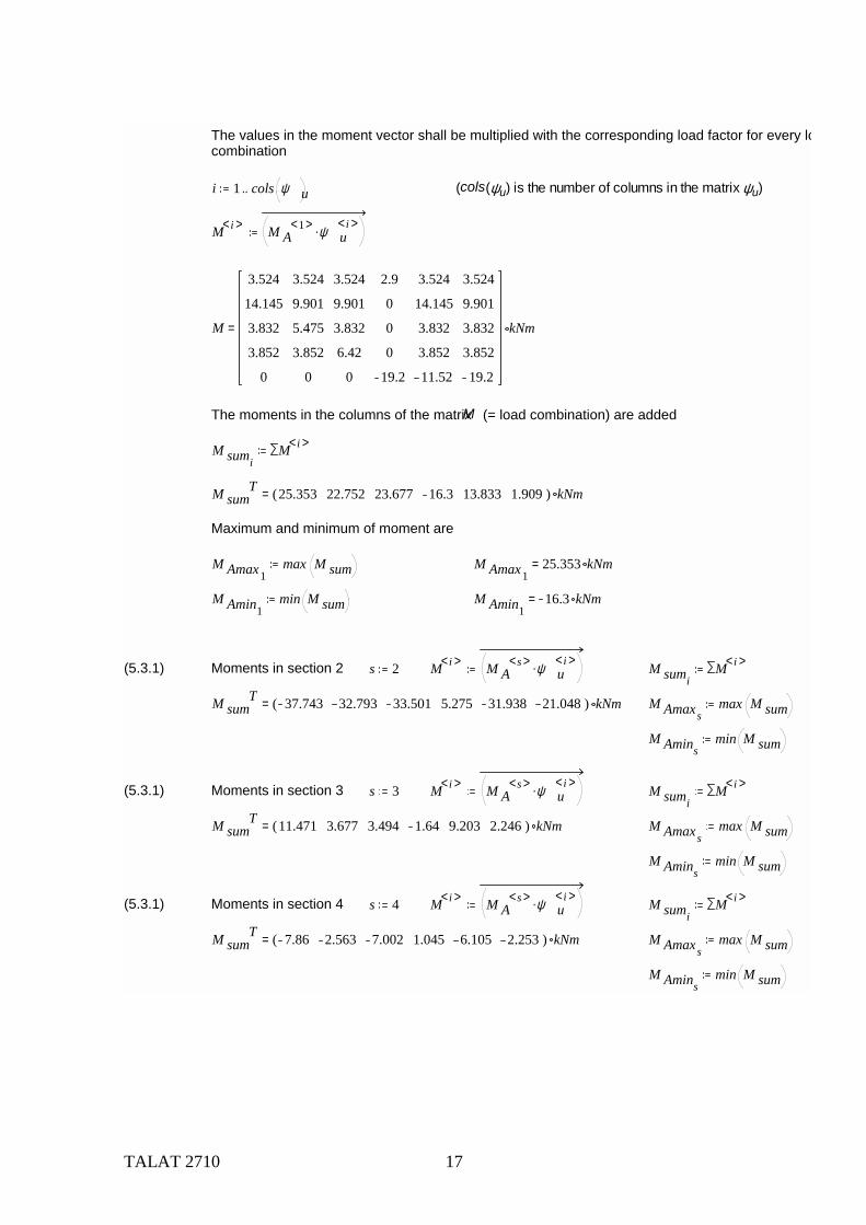
The values in the moment vector shall be multiplied with the corresponding load factor for every locombination
i 1 cols ψ u.. (cols(ψu) is the number of columns in the matrix ψu)
M i< > M A1< > ψ u
i< >.
M
3.524
14.145
3.832
3.852
0
3.524
9.901
5.475
3.852
0
3.524
9.901
3.832
6.42
0
2.9
0
0
0
19.2
3.524
14.145
3.832
3.852
11.52
3.524
9.901
3.832
3.852
19.2
kNm=
The moments in the columns of the matrix M (= load combination) are added
M sumiM i< >
M sumT 25.353 22.752 23.677 16.3 13.833 1.909( ) kNm=
Maximum and minimum of moment are
M Amax1max M sum M Amax1
25.353 kNm=
M Amin1min M sum M Amin1
16.3 kNm=
(5.3.1) Moments in section 2 s 2 M i< > M As< > ψ u
i< >. M sumiM i< >
M sumT 37.743 32.793 33.501 5.275 31.938 21.048( ) kNm= M Amaxs
max M sum
M Aminsmin M sum
(5.3.1) Moments in section 3 s 3 M i< > M As< > ψ u
i< >. M sumiM i< >
M sumT 11.471 3.677 3.494 1.64 9.203 2.246( ) kNm= M Amaxs
max M sum
M Aminsmin M sum
(5.3.1) Moments in section 4 s 4 M i< > M As< > ψ u
i< >. M sumiM i< >
M sumT 7.86 2.563 7.002 1.045 6.105 2.253( ) kNm= M Amaxs
max M sum
M Aminsmin M sum
TALAT 2710 18
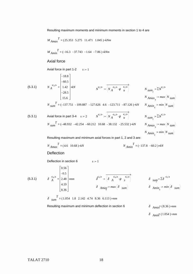
Resulting maximum moments and minimum moments in section 1 to 4 are
M AmaxT 25.353 5.275 11.471 1.045( ) kNm=
M AminT 16.3 37.743 1.64 7.86( ) kNm=
Axial force
Axial force in part 1-2 s 1
(5.3.1) N As< >
18.8
60.5
1.42
28.5
15.6
kN= N i< > N As< > ψ u
i< >. N sumiN i< >
N Amaxsmax N sum
N sumT 137.751 109.887 127.626 4.6 123.711 87.126( ) kN= N Amins
min N sum
(5.3.1) Axial force in part 3-4 s 2 N i< > N As< > ψ u
i< >. N sumiN i< >
N sumT 48.932 42.254 60.212 10.68 38.132 25.532( ) kN= N Amaxs
max N sum
N Aminsmin N sum
Resulting maximum and minimum axial forces in part 1, 2 and 3 are:
N AmaxT 4.6 10.68( ) kN= N Amin
T 137.8 60.2( ) kN=
Deflection
Deflection in section 6 s 1
(5.3.1) δ As< >
0.56
0.5
2.48
4.19
8.36
mm= δ i< > δ As< > ψ s
i< >. δ sumiδ i< >
δ Amaxsmax δ sum δ Amins
min δ sum
δ sumT 1.054 1.8 2.142 4.74 8.36 6.113( ) mm=
Resulting maximum and minimum deflection in section 6 δ Amax 8.36( ) mm=
δ Amin 1.054( ) mm=
TALAT 2710 19
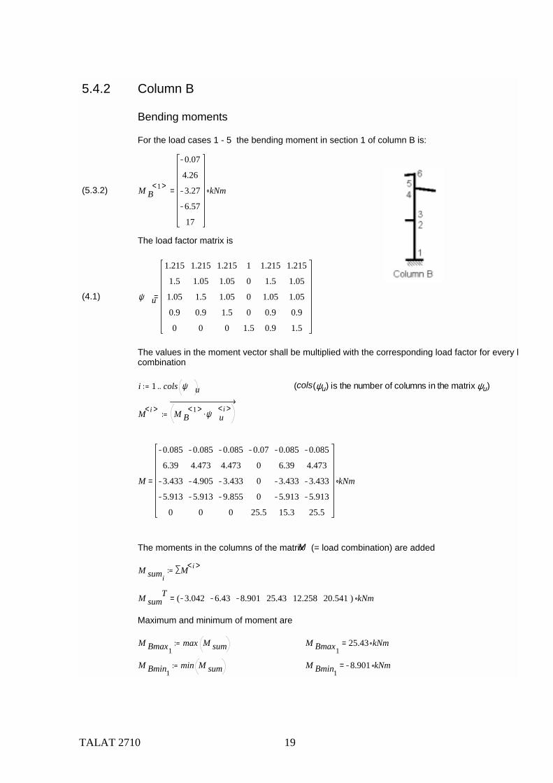
5.4.2 Column B
Bending moments
For the load cases 1 - 5 the bending moment in section 1 of column B is:
(5.3.2) M B1< >
0.07
4.26
3.27
6.57
17
kNm=
The load factor matrix is
(4.1) ψ u
1.215
1.5
1.05
0.9
0
1.215
1.05
1.5
0.9
0
1.215
1.05
1.05
1.5
0
1
0
0
0
1.5
1.215
1.5
1.05
0.9
0.9
1.215
1.05
1.05
0.9
1.5
=
The values in the moment vector shall be multiplied with the corresponding load factor for every lcombination
i 1 cols ψ u.. (cols(ψu) is the number of columns in the matrix ψu)
M i< > M B1< > ψ u
i< >.
M
0.085
6.39
3.433
5.913
0
0.085
4.473
4.905
5.913
0
0.085
4.473
3.433
9.855
0
0.07
0
0
0
25.5
0.085
6.39
3.433
5.913
15.3
0.085
4.473
3.433
5.913
25.5
kNm=
The moments in the columns of the matrix M (= load combination) are added
M sumiM i< >
M sumT 3.042 6.43 8.901 25.43 12.258 20.541( ) kNm=
Maximum and minimum of moment are
M Bmax1max M sum M Bmax1
25.43 kNm=
M Bmin1min M sum M Bmin1
8.901 kNm=
TALAT 2710 20
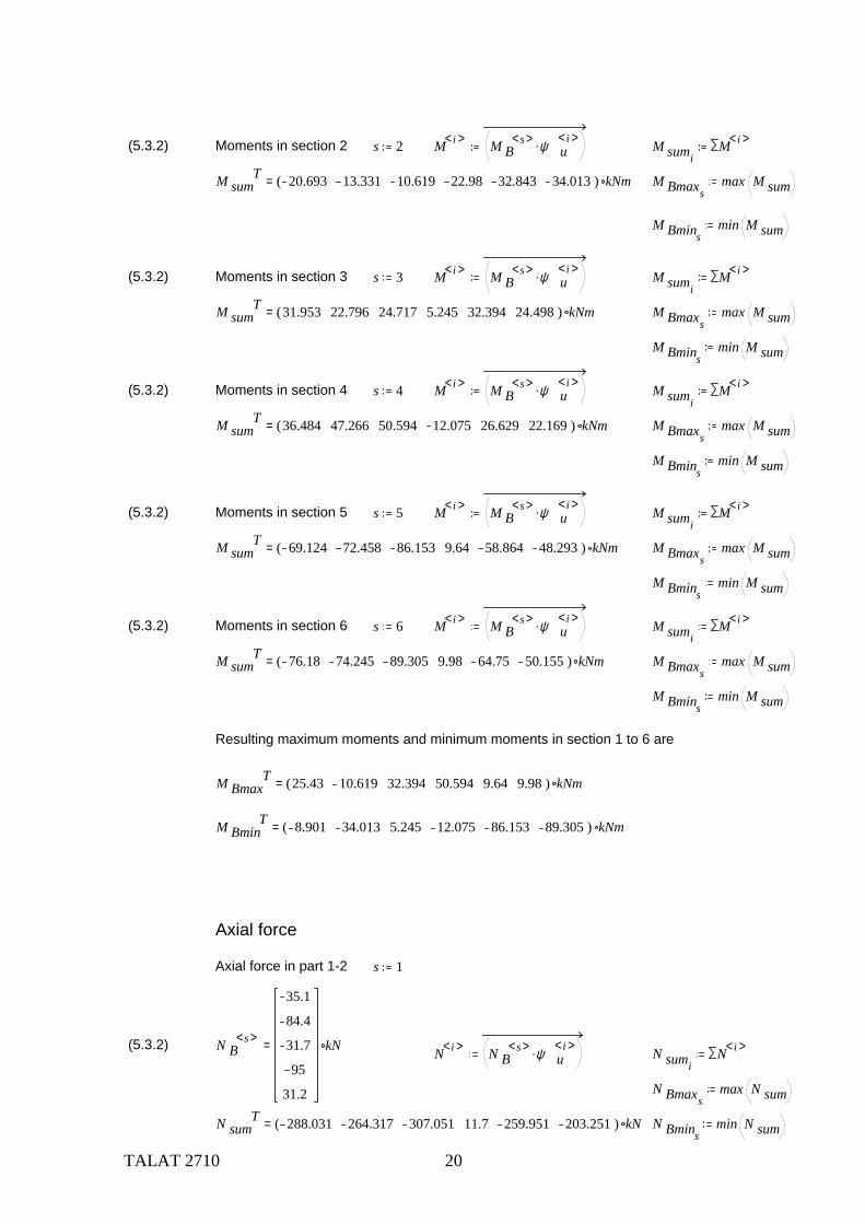
(5.3.2) Moments in section 2 s 2 M i< > M Bs< > ψ u
i< >. M sumiM i< >
M sumT 20.693 13.331 10.619 22.98 32.843 34.013( ) kNm= M Bmaxs
max M sum
M Bminsmin M sum
(5.3.2) Moments in section 3 s 3 M i< > M Bs< > ψ u
i< >. M sumiM i< >
M sumT 31.953 22.796 24.717 5.245 32.394 24.498( ) kNm= M Bmaxs
max M sum
M Bminsmin M sum
(5.3.2) Moments in section 4 s 4 M i< > M Bs< > ψ u
i< >. M sumiM i< >
M sumT 36.484 47.266 50.594 12.075 26.629 22.169( ) kNm= M Bmaxs
max M sum
M Bminsmin M sum
(5.3.2) Moments in section 5 s 5 M i< > M Bs< > ψ u
i< >. M sumiM i< >
M sumT 69.124 72.458 86.153 9.64 58.864 48.293( ) kNm= M Bmaxs
max M sum
M Bminsmin M sum
(5.3.2) Moments in section 6 s 6 M i< > M Bs< > ψ u
i< >. M sumiM i< >
M sumT 76.18 74.245 89.305 9.98 64.75 50.155( ) kNm= M Bmaxs
max M sum
M Bminsmin M sum
Resulting maximum moments and minimum moments in section 1 to 6 are
M BmaxT 25.43 10.619 32.394 50.594 9.64 9.98( ) kNm=
M BminT 8.901 34.013 5.245 12.075 86.153 89.305( ) kNm=
Axial force
Axial force in part 1-2 s 1
(5.3.2) N Bs< >
35.1
84.4
31.7
95
31.2
kN= N i< > N Bs< > ψ u
i< >. N sumiN i< >
N Bmaxsmax N sum
N sumT 288.031 264.317 307.051 11.7 259.951 203.251( ) kN= N Bmins
min N sum
TALAT 2710 21
(5.3.2) Axial force in part 3-4 s 2 N i< > N Bs< > ψ u
i< >. N sumiN i< >
N sumT 198.187 196.927 240.352 28.7 166.868 130.732( ) kN= N Bmaxs
max N sum
N Bminsmin N sum
(5.3.2) Axial force in part 5-6 s 3 N i< > N Bs< > ψ u
i< >. N sumiN i< >
N sumT 69.291 65.484 86.451 11.52 56.871 42.831( ) kN= N Bmins
min N sum
N Bmaxsmax N sum
Resulting maximum and minimum axial forces in part 1, 2 and 3 are:
N BmaxT 11.7 28.7 11.52( ) kN= N Bmin
T 307.1 240.4 86.5( ) kN=
Deflection
Deflection in section 6 s 1
(5.3.2) δ Bs< >
0.57
0.53
2.57
4.3
8.32
mm= δ i< > δ Bs< > ψ s
i< >. δ sumiδ i< >
δ Bmaxsmax δ sum δ Bmins
min δ sum
δ sumT 1.076 1.855 2.201 4.73 8.32 6.276( ) mm=
Resulting maximum and minimum deflection in section 6 δ Bmax 8.32( ) mm=
δ Bmin 1.076( ) mm=
5.4.3 Column CComment: To reduce the extent of this example, calculation of this column is left out. It can, conservatively, be given the same dimensions as column B
TALAT 2710 22
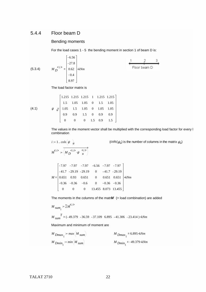
5.4.4 Floor beam D
Bending moments
For the load cases 1 - 5 the bending moment in section 1 of beam D is:
(5.3.4) M D1< >
6.56
27.8
0.62
0.4
8.97
kNm=
The load factor matrix is
(4.1) ψ u
1.215
1.5
1.05
0.9
0
1.215
1.05
1.5
0.9
0
1.215
1.05
1.05
1.5
0
1
0
0
0
1.5
1.215
1.5
1.05
0.9
0.9
1.215
1.05
1.05
0.9
1.5
=
The values in the moment vector shall be multiplied with the corresponding load factor for every lcombination
i 1 cols ψ u.. (cols(ψu) is the number of columns in the matrix ψu)
M i< > M D1< > ψ u
i< >.
M
7.97
41.7
0.651
0.36
0
7.97
29.19
0.93
0.36
0
7.97
29.19
0.651
0.6
0
6.56
0
0
0
13.455
7.97
41.7
0.651
0.36
8.073
7.97
29.19
0.651
0.36
13.455
kNm=
The moments in the columns of the matrix M (= load combination) are added
M sumiM i< >
M sumT 49.379 36.59 37.109 6.895 41.306 23.414( ) kNm=
Maximum and minimum of moment are
M Dmax1max M sum M Dmax1
6.895 kNm=
M Dmin1min M sum M Dmin1
49.379 kNm=
TALAT 2710 23
(5.3.4) Moments in section 2 s 2 M i< > M Ds< > ψ u
i< >. M sumiM i< >
M sumT 84.597 67.164 65.949 13.4 86.397 67.977( ) m kN= M Dmins
min M sum
M Dmaxsmax M sum
(5.3.4) Moments in section 3 s 3 M i< > M Ds< > ψ u
i< >. M sumiM i< >
M sumT 52.658 36.139 35.348 26.75 64.358 57.038( ) m kN= M Dmins
min M sum
M Dmaxsmax M sum
Resulting maximum moments and minimum moments in section 1 to 3 are
M Dmax
6.895
86.397
26.75
kNm= M Dmin
49.379
13.4
64.358
kNm=
Shear force
Shear force in section 1 s 1
(5.3.4) V Ds< >
11.7
48.5
1.4
0.67
3.66
kN= V i< > V Ds< > ψ u
i< >. V sumiV i< >
V Dmaxsmax V sum V Dmins
min V sum
V sumT 89.038 67.844 67.615 6.21 85.745 61.723( ) kN=
Shear force in section 2 s 2
(5.3.4) V Ds< >
11.4
50.5
0.6
0.67
3.66
kN= V i< > V Ds< > ψ u
i< >. V sumiV i< >
V Dmaxsmax V sum V Dmins
min V sum
V sumT 88.368 65.373 65.241 16.89 91.662 71.133( ) kN=
Resulting maximum and minimum shear forces in section 1 and 3 are
V Dmax89.038
91.662kN= V Dmin
6.21
16.89kN=
Deflection
TALAT 2710 24
V Dmax89.038
91.662kN= V Dmin
6.21
16.89kN=
Deflection
Deflection in section 2 s 1
(5.3.4) δ Ds< >
3.21
13.1
1.63
0.92
0.91
mm= δ i< > δ Ds< > ψ s
i< >. δ sumiδ i< >
δ Dmaxsmax δ sum δ Dmins
min δ sum
δ sumT 10.249 4.025 3.883 2.755 0.91 17.295( ) mm=
Resulting maximum and minimum deflection in section 2
δ Dmax 17.295( ) mm= δ Dmin 0.91( ) mm=
5.4.5 Roof beam EComment: To reduce the extent of this example, calculation of this beam is left out. It can be giventhe same dimensions as floor beam D
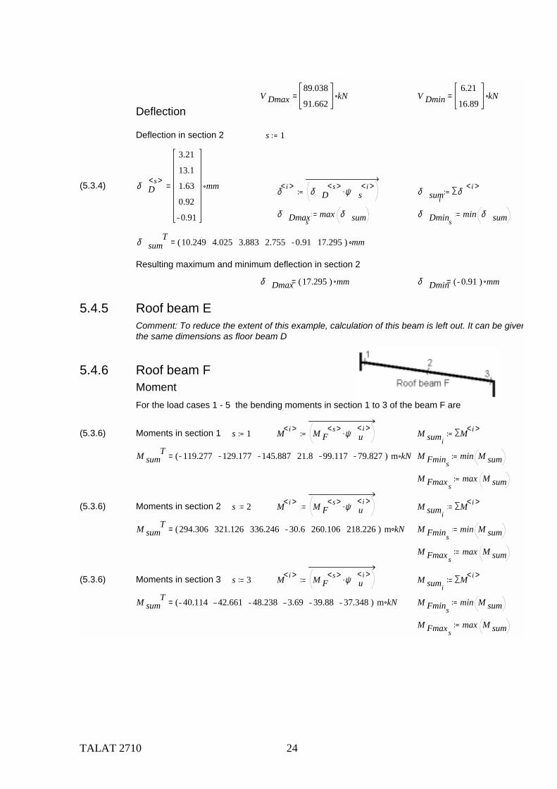
5.4.6 Roof beam FMoment For the load cases 1 - 5 the bending moments in section 1 to 3 of the beam F are
(5.3.6) Moments in section 1 s 1 M i< > M Fs< > ψ u
i< >. M sumiM i< >
M sumT 119.277 129.177 145.887 21.8 99.117 79.827( ) m kN= M Fmins
min M sum
M Fmaxsmax M sum
(5.3.6) Moments in section 2 s 2 M i< > M Fs< > ψ u
i< >. M sumiM i< >
M sumT 294.306 321.126 336.246 30.6 260.106 218.226( ) m kN= M Fmins
min M sum
M Fmaxsmax M sum
(5.3.6) Moments in section 3 s 3 M i< > M Fs< > ψ u
i< >. M sumiM i< >
M sumT 40.114 42.661 48.238 3.69 39.88 37.348( ) m kN= M Fmins
min M sum
M Fmaxsmax M sum
TALAT 2710 25
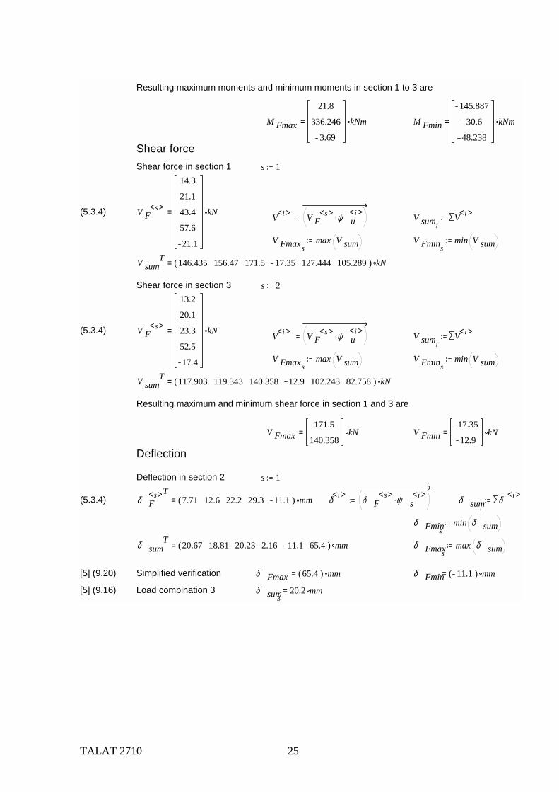
Resulting maximum moments and minimum moments in section 1 to 3 are
M Fmax
21.8
336.246
3.69
kNm= M Fmin
145.887
30.6
48.238
kNm=
Shear forceShear force in section 1 s 1
(5.3.4) V Fs< >
14.3
21.1
43.4
57.6
21.1
kN= V i< > V Fs< > ψ u
i< >. V sumiV i< >
V Fmaxsmax V sum V Fmins
min V sum
V sumT 146.435 156.47 171.5 17.35 127.444 105.289( ) kN=
Shear force in section 3 s 2
(5.3.4) V Fs< >
13.2
20.1
23.3
52.5
17.4
kN= V i< > V Fs< > ψ u
i< >. V sumiV i< >
V Fmaxsmax V sum V Fmins
min V sum
V sumT 117.903 119.343 140.358 12.9 102.243 82.758( ) kN=
Resulting maximum and minimum shear force in section 1 and 3 are
V Fmax171.5
140.358kN= V Fmin
17.35
12.9kN=
Deflection
Deflection in section 2 s 1
(5.3.4) δ Fs< >T
7.71 12.6 22.2 29.3 11.1( ) mm= δ i< > δ Fs< > ψ s
i< >. δ sumiδ i< >
δ Fminsmin δ sum
δ sumT 20.67 18.81 20.23 2.16 11.1 65.4( ) mm= δ Fmaxs
max δ sum
[5] (9.20) Simplified verification δ Fmax 65.4( ) mm= δ Fmin 11.1( ) mm=
[5] (9.16) Load combination 3 δ sum320.2 mm=
TALAT 2710 26
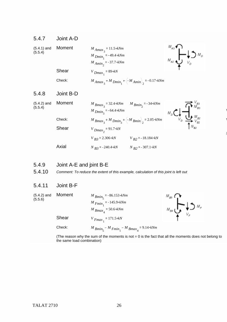
5.4.7 Joint A-D
(5.4.1) and(5.5.4)
Moment M Amax311.5 kNm=
M Dmin149.4 kNm=
M Amin237.7 kNm=
Shear V Dmax189 kN=
Check: M Amax3M Dmin1
M Amin 20.17 kNm=
5.4.8 Joint B-D
(5.4.2) and(5.5.4)
Moment M Bmax332.4 kNm= M Bmin2
34 kNm=
M Dmin364.4 kNm= V
Check: M Bmax3M Dmin3
M Bmin 22.05 kNm= V
Shear V Dmax291.7 kN=
NV B3 2.306 kN= V B2 18.184 kN=
Axial N B3 240.4 kN= N B2 307.1 kN=
5.4.9 Joint A-E and joint B-E 5.4.10 Comment: To reduce the extent of this example, calculation of this joint is left out
5.4.11 Joint B-F
(5.4.2) and(5.5.6)
Moment M Bmin586.153 kNm=
M Fmin1145.9 kNm=
M Bmax450.6 kNm=
Shear V Fmax1171.5 kN=
Check: M Bmin5M Fmin1
M Bmax49.14 kNm=
(The reason why the sum of the moments is not = 0 is the fact that all the moments does not belong to the same load combination)
TALAT 2710 27
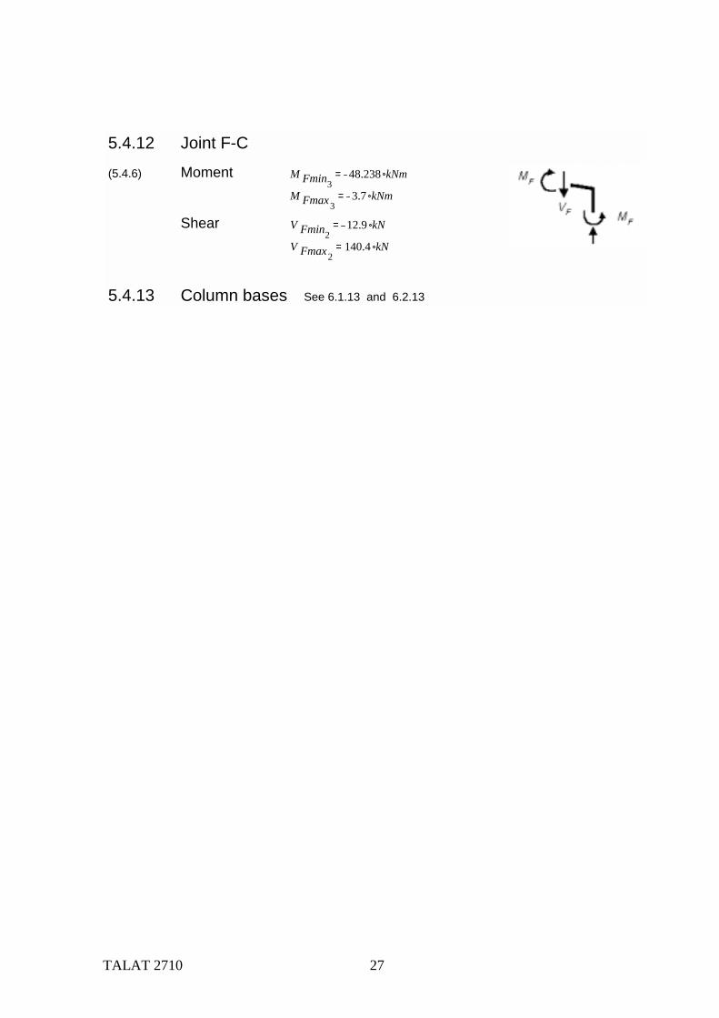
5.4.12 Joint F-C
(5.4.6) Moment M Fmin348.238 kNm=
M Fmax33.7 kNm=
Shear V Fmin212.9 kN=
V Fmax2140.4 kN=
5.4.13 Column bases See 6.1.13 and 6.2.13
TALAT 2710 28
6. Code Checking
6.1 Column A
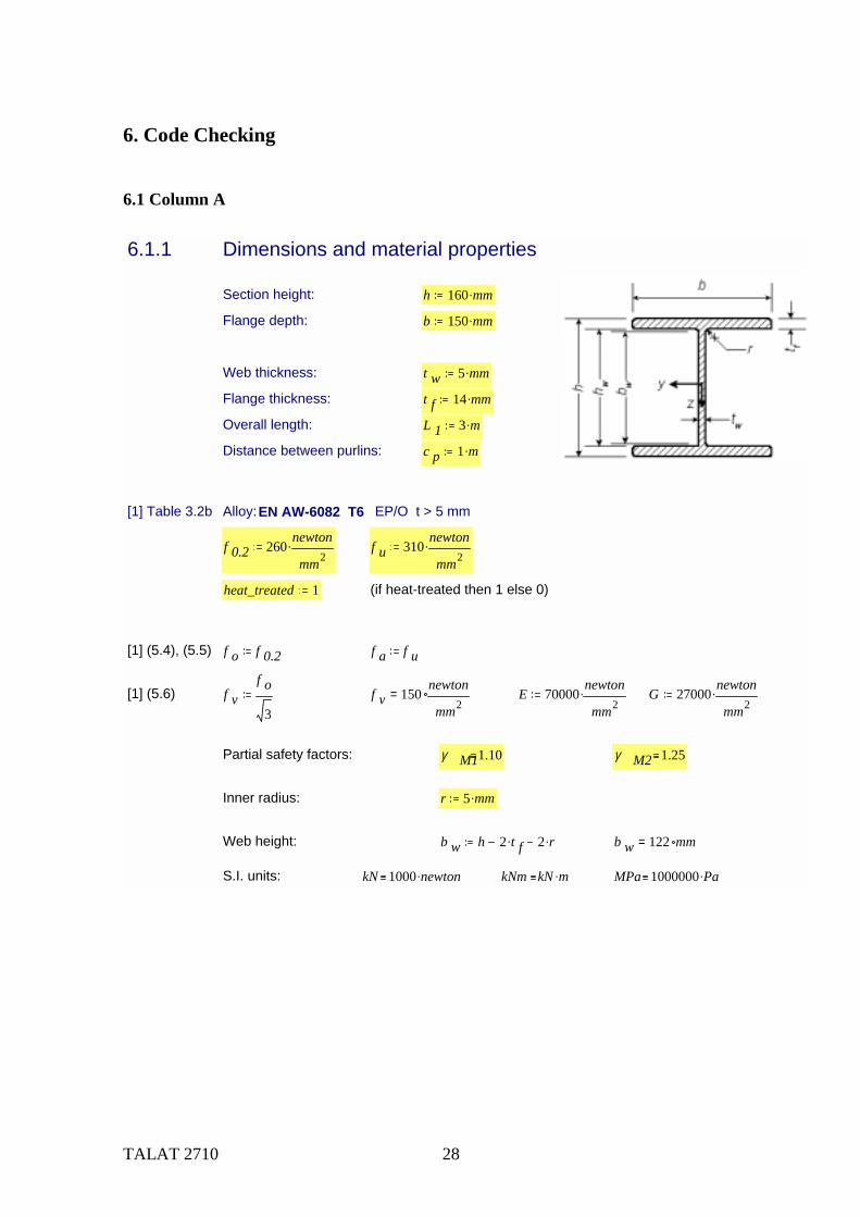
6.1.1 Dimensions and material properties
Section height: h 160 mm.
Flange depth: b 150 mm.
Web thickness: t w 5 mm.
Flange thickness: t f 14 mm.
Overall length: L 1 3 m.
Distance between purlins: c p 1 m.
[1] Table 3.2b Alloy: EN AW-6082 T6 EP/O t > 5 mm
f 0.2 260newton
mm2. f u 310
newton
mm2.
heat_treated 1 (if heat-treated then 1 else 0)
[1] (5.4), (5.5) f o f 0.2 f a f u
[1] (5.6) f vf o
3f v 150
newton
mm2= E 70000
newton
mm2. G 27000
newton
mm2.
Partial safety factors: γ M11.10 γ M2 1.25
Inner radius: r 5 mm.
Web height: b w h 2 t f. 2 r. b w 122 mm=
S.I. units: kN 1000 newton. kNm kN m. MPa 1000000 Pa.
TALAT 2710 29
6.1.2 Internal moments and forces
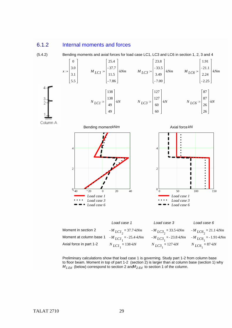
(5.4.2) Bending moments and axial forces for load case LC1, LC3 and LC6 in section 1, 2, 3 and 4
x
0
3.0
3.1
5.5
M LC1
25.4
37.7
11.5
7.86
kNm. M LC3
23.8
33.5
3.49
7.00
kNm. M LC6
1.91
21.1
2.24
2.25
kNm.
N LC1
138
138
49
49
kN. N LC3
127
127
60
60
kN. N LC6
87
87
26
26
kN.
40 20 0 20 400
2
4
Load case 1Load case 3Load case 6
Bending moment kNm
0 50 100 1500
2
4
Load case 1Load case 3Load case 6
Axial force kN
Load case 1 Load case 3 Load case 6
Moment in section 2 M LC1237.7 kNm= M LC32
33.5 kNm= M LC6221.1 kNm=
Moment at column base 1 M LC1125.4 kNm= M LC31
23.8 kNm= M LC611.91 kNm=
Axial force in part 1-2 N LC11138 kN= N LC31
127 kN= N LC6187 kN=
Preliminary calculations show that load case 1 is governing. Study part 1-2 from column baseto floor beam. Moment in top of part 1-2 (section 2) is larger than at column base (section 1) why M1.Ed (below) correspond to section 2 and M2.Ed to section 1 of the column.
TALAT 2710 30
Load case 1
Bending moment in section 2 M 1.Ed M LC12M 1.Ed 37.7 kNm=
Bending moment at column base (1) M 2.Ed M LC11M 2.Ed 25.4 kNm=
Axial force in part 1-2 (compression) N Ed N LC11N Ed 138 kN=
6.1.3 Classification of the cross section in y-y-axis bending β w bendingbendingbending
a) Web[1] 5.4.3 b 1 b w t 1 t w β w 0.40
b 1t 1
. β w 9.76=
[1] Tab. 5.1 ε250f o
newton
mm2. β 1w 11 ε. β 1w 10.786=
Heat treated,unwelded = no longitudinal weld
β 2w 16 ε. β 2w 15.689=
β 3w 22 ε. β 3w 21.573=
class w if β wβ 1w> if β w β 2w> if β w β 3w> 4, 3,, 2,, 1, class w 1=
[1] 5.4.5 Local buckling
ρ cw ifβ w
ε22 1.0,
32β w
ε
220
β wε
2, ρ cw 1=
t w.ef.b if class w 4 t w ρ cw., t w, ( b = bending) t w.ef.b 5.0 mm=
b) Flanges[1] 5.4.3 ψ 1
[1] (5.7.),(5.8.) g if ψ 1> 0.7 0.3 ψ.,0.8
1 ψ, g 1=
b 2b t w 2 r.
2t 2 t f β f g
b 2t 2
. β f 4.821=
[1] Tab. 5.1 ε 0.981= β 1f 3 ε. β 1f 2.942=
β 2f 4.5 ε. β 2f 4.413=
β 3f 6 ε. β 3f 5.883=
class f if β fβ 1f> if β f β 2f> if β f β 3f> 4, 3,, 2,, 1, class f 3=
TALAT 2710 31
[1] 5.4.5 Local buckling:
ρ cf ifβ fε
6 1.0,10
β fε
24
β fε
2, ρ cf 1=
t f.ef if class f 4 t f ρ cf., t f, t f.ef 14.0 mm=
Classification of the cross-section in y-y axis bending
class y if class f class w> class f, class w, class y 3=
6.1.4 Classification of the cross section in z-z-axis bending
Cross section class of web: No bending stresses class w 1
Cross section class for flanges: According to above class f 3=
class z if class f class w> class f, class w, class z 3=
6.1.5 Classification of the cross section in axial compression
β wc compressioncompressioncompressiona) Webb 1 b w t 1 t w β wc
b 1t 1
β wc 24.4=
[1] Tab. 5.1 β 1w 10.786=
β 2w 15.689=
β 3w 21.573=
class wc if β wcβ 1w> if β wc β 2w> if β wc β 3w> 4, 3,, 2,, 1, class wc 4=
[1] 5.4.5 Local buckling
ρ cw ifβ wc
ε22 1.0,
32β wc
ε
220
β wcε
2, ρ cw 0.931=
t w.ef if class wc 4 t w ρ cw., t w, t w 5 mm= t w.ef 4.7 mm=
b) FlangesSame as in bending t f.ef 14.0 mm= class f 3=
Classification of the total cross-section in axial compressionclass c if class f class wc> class f, class wc, class c 4=
TALAT 2710 32
6.1.6. Welds
[1] 5.5 HAZ softening at column ends
[1] Tab.5.2 ρ haz 0.65
[1] Fig.5.6 Extent of HAZ (MIG-weld) t 1 t f
b haz if t 1 6 mm.> if t 1 12 mm.> if t 1 25 mm.> 40 mm., 35 mm.,, 30 mm.,, 20 mm.,
b haz 35 mm=
6.1.7 Design resistance, y-y-axis bending
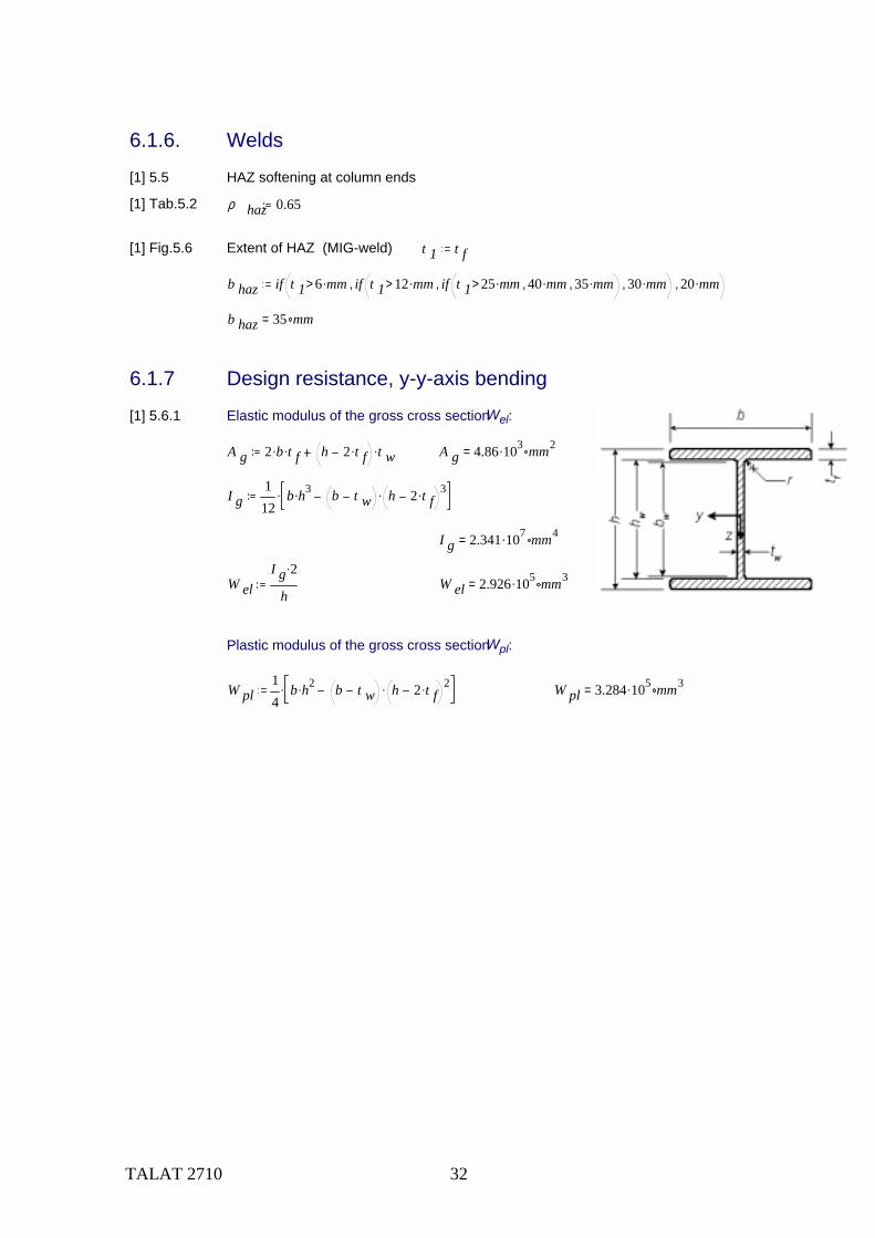
[1] 5.6.1 Elastic modulus of the gross cross section Wel:
A g 2 b. t f. h 2 t f. t w. A g 4.86 103. mm2=
I g112
b h3. b t w h 2 t f. 3..
I g 2.341 107. mm4=
W elI g 2.
hW el 2.926 105. mm3=
Plastic modulus of the gross cross section Wpl:
W pl14
b h2. b t w h 2 t f. 2.. W pl 3.284 105. mm3=
TALAT 2710 33
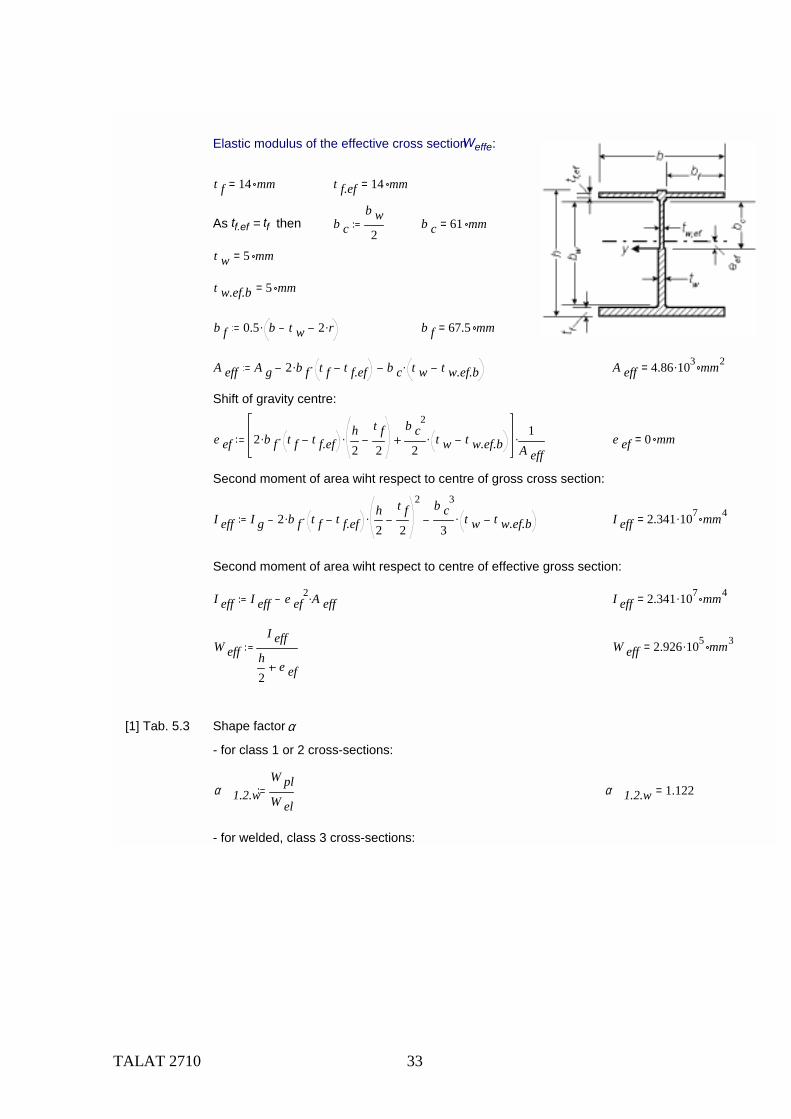
Elastic modulus of the effective cross section Weffe:
t f 14 mm= t f.ef 14 mm=
As tf.ef = tf then b cb w2
b c 61 mm=
t w 5 mm=
t w.ef.b 5 mm=
b f 0.5 b t w 2 r.. b f 67.5 mm=
A eff A g 2 b f. t f t f.ef. b c t w t w.ef.b. A eff 4.86 103. mm2=
Shift of gravity centre:
e ef 2 b f. t f t f.ef. h2
t f2
.b c
2
2t w t w.ef.b. 1
A eff. e ef 0 mm=
Second moment of area wiht respect to centre of gross cross section:
I eff I g 2 b f. t f t f.ef. h2
t f2
2
.b c
3
3t w t w.ef.b. I eff 2.341 107. mm4=
Second moment of area wiht respect to centre of effective gross section:
I eff I eff e ef2 A eff. I eff 2.341 107. mm4=
W effI eff
h2
e ef
W eff 2.926 105. mm3=
[1] Tab. 5.3 Shape factor α
- for class 1 or 2 cross-sections:
α 1.2.wW plW el
α 1.2.w 1.122=
- for welded, class 3 cross-sections:
TALAT 2710 34
[1] Tab. 5.3 Shape factor α
- for class 1 or 2 cross-sections:
α 1.2.wW plW el
α 1.2.w 1.122=
- for welded, class 3 cross-sections:
[1] (5.16) α 3.ww 1β 3w β w
β 3w β 2w
W pl W elW el
. α 3.ww 1.245=
[1] (5.16) α 3.wf 1β 3f β f
β 3f β 2f
W pl W elW el
. α 3.wf 1.088=
β, β2, β3 are the slenderness parameter and the limiting values for the most critical element in the cross-section, so it is the smaller value of α3.ww and α3.wf
α 3.w if α 3.ww α 3.wf α 3.ww, α 3.wf, α 3.w 1.088=
- for class 4 cross-sections: α 4.wW effW el
α 4.w 1=
class y 3=
α y if class y 2> if class y 3> α 4.w, α 3.w,, α 1.2.w, α y 1.088=
Design moment of resistance of the cross section Mc,Rd
[1] (5.14) M y.Rdf o α y. W el.
γ M1M y.Rd 75.3 kNm=
6.1.8 Design resistance, z-z-axis bending
Cross section class class z 3=
Gross cross section: I z 2t f b3.
12. I z 7.875 106. mm4=
Effective cross section: I z.ef 2t f.ef b3.
12. I z.ef 7.875 106. mm4=
Section moduli: W zI z 2.
bW z.ef
I z.ef 2.
b
Shape factor: α zW z
W z.efα z 1=
Bending resistance: M z.Rdf o α z. W z.
γ M1M z.Rd 24.818 kNm=
TALAT 2710 35
6.1.9 Axial force resistance, y-y buckling
[1] 5.8.4 Cross section area of gross cross section Agr
A gr b h. b t w h 2 t f.. A gr 4.86 103. mm2=
Cross section area of effective cross section Aef t w.ef 4.653 mm=
A ef A gr 2 b 2. t f t f.ef. b w t w t w.ef. A ef 4.818 103. mm2=
( t f 14 mm= t w 5 mm= 2 b 2. 135 mm= t f.ef 14 mm= t w.ef 4.653 mm= )
Effective cross section factor ηA efA gr
η 0.991=
Second moment of area of gross cross section Iy:
I y212
b. t f3. 2 b. t f.
h t f2
2
. 112
h 2 t f. 3. t w.
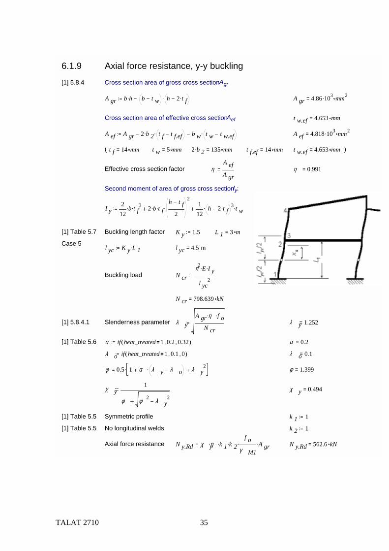
[1] Table 5.7 Buckling length factor K y 1.5 L 1 3 m=
Case 5 l yc K y L 1. l yc 4.5 m=
Buckling load N crπ2 E. I y.
l yc2
N cr 798.639 kN=
[1] 5.8.4.1 Slenderness parameter λ yA gr η. f o.
N crλ y 1.252=
[1] Table 5.6 α if heat_treated 1 0.2, 0.32,( ) α 0.2=
λ o if heat_treated 1 0.1, 0,( ) λ o 0.1=
φ 0.5 1 α λ y λ o. λ y2. φ 1.399=
χ y1
φ φ 2 λ y2
χ y 0.494=
[1] Table 5.5 Symmetric profile k 1 1
[1] Table 5.5 No longitudinal welds k 2 1
Axial force resistance N y.Rd χ yη. k 1. k 2.f o
γ M1. A gr. N y.Rd 562.6 kN=
TALAT 2710 36
6.1.10 Axial force resistance, z-z axis buckling
Buckling length = distance between purlins K zc pL 1
K z L 1. 1 m=
Buckling load N crπ2 E. I z.
K z L 1. 2N cr 5.4 103. kN=
[1] 5.8.4.1 Slenderness factor λ zA gr η. f o.
N crλ z 0.48=
[1] Table 5.6 α if heat_treated 1 0.2, 0.32,( ) α 0.2=
λ o if heat_treated 1 0.1, 0,( ) λ o 0.1=
[1] 5.8.4.1 φ 0.5 1 α λ z λ o. λ z2. φ 0.653=
χ z1
φ φ 2 λ z2
χ z 0.912=
k 1 1[1] Table 5.5 Symmetric profile
[1] Table 5.5 No longitudinal welds k 2 1=
[1] 5.8.4.1 Axial load resistance N z.Rd χ zη. k 1. k 2.f o
γ M1. A gr. N z.Rd 1.039 103. kN=
(6.1.9) Compare y-y axis buckling N y.Rd 562.622 kN=
and without column buckling N Rd ηf o
γ M1. A gr. N Rd 1.139 103. kN=
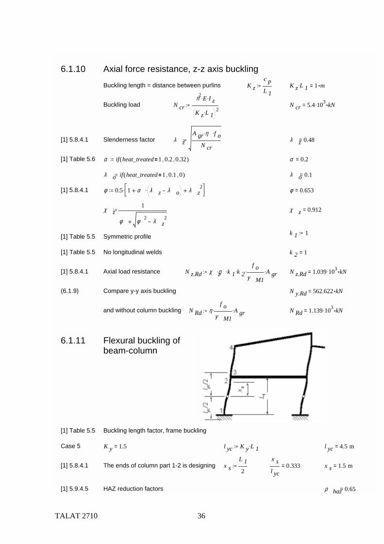
6.1.11 Flexural buckling ofbeam-column
[1] Table 5.5 Buckling length factor, frame buckling
Case 5 K y 1.5= l yc K y L 1. l yc 4.5 m=
[1] 5.8.4.1 The ends of column part 1-2 is designing x sL 12
x sl yc
0.333= x s 1.5 m=
[1] 5.9.4.5 HAZ reduction factors ρ haz 0.65=
TALAT 2710 37
[1] (5.51) ω 0 ρ hazf u
γ M2.
γ M1f o
. ω 0 if ω 0 1> 1, ω 0, ω 0 0.682=
[1] (5.49) ω xω 0
χ y 1 χ y sinπ x s.
l yc.
ω x 0.732=
Exponents in interaction formulae
[1] (5.42c) ξ 0 α y2 ξ 0 if ξ 0 1< 1, ξ 0, ξ 0 1.184=
[1] 5.9.4.2 ξ yc ξ 0 χ y. ξ yc if ξ yc 0.8< 0.8, ξ yc, ξ yc 0.8=
Flexural buckling check
Bending moment M y.Ed M 1.Ed M y.Ed 37.7 kNm=
[1] 5.4.4 U yN Ed
χ zω x. N Rd.
ξ yc M y.Edω 0 M y.Rd.
U y 0.99=
or with simplified exponents
U ysN Ed
χ zω x. N Rd.
0.8 M y.Edω 0 M y.Rd.
1.0
U ys 0.99=
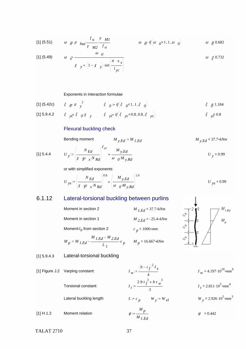
6.1.12 Lateral-torsional buckling between purlins
Moment in section 2 M 1.Ed 37.7 kNm=
Moment in section 1 M 2.Ed 25.4 kNm=
Moment cp from section 2 c p 1000 mm=
M p M 1.EdM 1.Ed M 2.Ed
L 1c p. M p 16.667 kNm=
[1] 5.9.4.3 Lateral-torsional buckling
[1] Figure J.2 Varping constant: I wh t f
2 I z.
4I w 4.197 1010. mm6=
Torsional constant: I t2 b. t f
3. h t w3.
3I t 2.811 105. mm4=
Lateral buckling length L c p W y W el W y 2.926 105. mm3=
[1] H.1.2 Moment relation ψM p
M 1.Edψ 0.442=
TALAT 2710 38
[1] H.1.2(6) C1 - constant C 1 1.88 1.4 ψ. 0.52 ψ 2. C 1 1.363=
Shear modulus GE
2.6G 2.692 104. MPa=
[1] H.1.3(3) M crC 1 π2. E. I z.
L2
I wI z
L2 G. I t.
π 2 E. I z.. L 1000 mm= M cr 607.759 kNm=
[1] 5.6.6.3(3) λ LTα y W y. f o.
M crλ LT 0.369=
[1] 5.6.6.3(2) α LT if class z 2> 0.2, 0.1, α LT 0.2=
λ 0LT if class z 2> 0.4, 0.6, λ 0LT 0.4=
[1] 5.6.6.3(1) φ LT 0.5 1 α LT λ LT λ 0LT. λ LT2. φ LT 0.565=
χ LT1
φ LT φ LT2 λ LT
2χ LT 1.007=
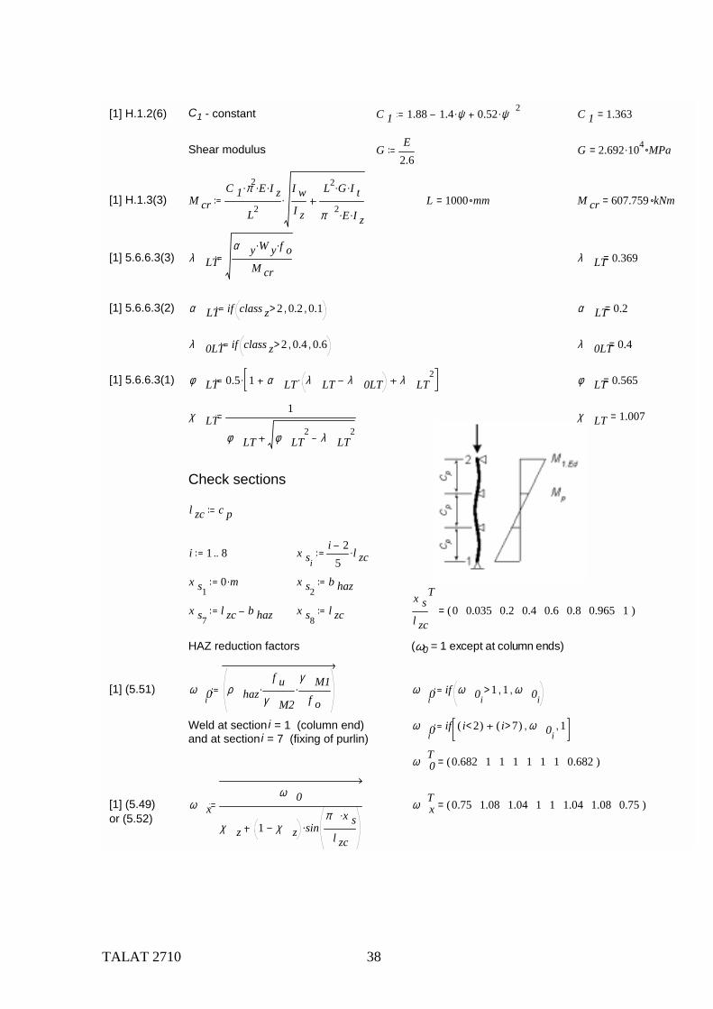
Check sections
l zc c p
i 1 8.. x si
i 25
l zc.
x s10 m. x s2
b haz
x s7l zc b haz x s8
l zcx sl zc
T0 0.035 0.2 0.4 0.6 0.8 0.965 1( )=
HAZ reduction factors (ω0 = 1 except at column ends)
[1] (5.51) ω 0iρ haz
f uγ M2
.γ M1
f o. ω 0i
if ω 0i1> 1, ω 0i
,
Weld at section i = 1 (column end) and at section i = 7 (fixing of purlin)
ω 0iif i 2<( ) i 7>( ) ω 0i
, 1,
ω 0T 0.682 1 1 1 1 1 1 0.682( )=
[1] (5.49) ω xω 0
χ z 1 χ z sinπ x s.
l zc.
ω xT 0.75 1.08 1.04 1 1 1.04 1.08 0.75( )=
or (5.52)
TALAT 2710 39
[1] (5.50) ω xLTω 0
χ LT 1 χ LT sinπ x s.
l zc.
ω xLTT 0.68 0.99 1 1 1 1 0.99 0.68( )=
or (5.53)
[1] (5.42a) η 0 α z2 α y
2. η 0 if η 0 1< 1, if η 0 2> 2, η 0,, η 0 1.184=
[1] (5.42b) γ 0 α z2 γ 0 if γ 0 1< 1, if γ 0 2> 2, γ 0,, γ 0 1=
[1] (5.42c) ξ 0 α y2 ξ 0 if ξ 0 1< 1, ξ 0, ξ 0 1.184=
[1] 5.9.4.3 η c η 0 χ z. η c if η c 0.8< 0.8, η c, χ y 0.494= η c 1.08=
γ c γ 0 χ z 0.912= γ c 1=
ξ zc ξ 0 χ z. ξ zc if ξ zc 0.8< 0.8, ξ zc, ξ zc 1.08=
Lateral-torsional buckling of beam-column
Bending moment in section xs M y.Ed M 1.Ed M 1.Ed M px sl zc
.
M y.EdM 1.Ed
T1 0.98 0.888 0.777 0.665 0.554 0.462 0.442( )=M z.Ed 0 kNm.
[1] (5.43) U LTN Ed
χ zω x. N Rd.
η c M y.Edχ LT ω xLT. M y.Rd.
γ c M z.Edω 0 M z.Rd.
ξ zc
U LTT 0.889 0.594 0.552 0.499 0.443 0.385 0.334 0.479( )=
TALAT 2710 40
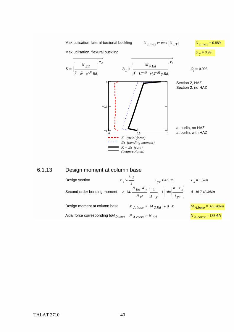
Max utilisation, lateral-torsional buckling U z.max max U LT U z.max 0.889=
Max utilisation, flexural buckling U y 0.99=
KN Ed
χ zω x. N Rd.
η c
B zM y.Ed
χ LT ω xLT. M y.Rd.
γ c
Oi 0.005
0 0.5 11
0.5
0
K (axial force)Bz (bending moment)K + Bz (sum)(beam-column)
Section 2, HAZSection 2, no HAZ
at purlin, no HAZat purlin, with HAZ
6.1.13 Design moment at column base
Design section x sL 12
l yc 4.5 m= x s 1.5 m=
Second order bending moment ∆ MN Ed W y.
A ef
1χ y
1. sinπ x s.
l yc. ∆ M 7.43 kNm=
Design moment at column base M A.base M 2.Ed ∆ M M A.base 32.8 kNm=
Axial force corresponding to MD.base N A.corre N Ed N A.corre 138 kN=
TALAT 2710 41
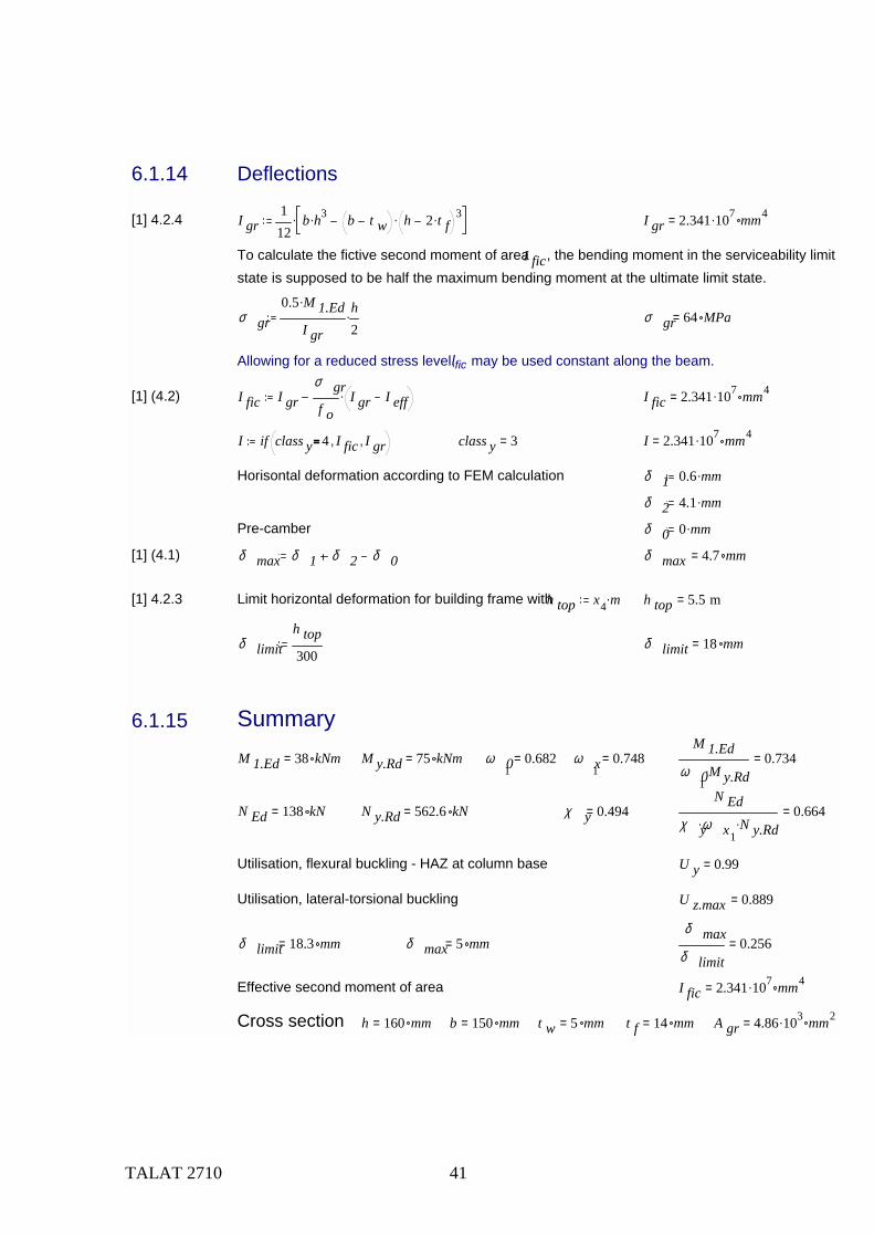
6.1.14 Deflections
[1] 4.2.4 I gr112
b h3. b t w h 2 t f. 3.. I gr 2.341 107. mm4=
To calculate the fictive second moment of area I fic, the bending moment in the serviceability limit state is supposed to be half the maximum bending moment at the ultimate limit state.
σ gr0.5 M 1.Ed.
I gr
h2
. σ gr 64 MPa=
Allowing for a reduced stress level, Ific may be used constant along the beam.
[1] (4.2) I fic I grσ grf o
I gr I eff. I fic 2.341 107. mm4=
I if class y 4 I fic, I gr, class y 3= I 2.341 107. mm4=
Horisontal deformation according to FEM calculation δ 1 0.6 mm.
δ 2 4.1 mm.
Pre-camber δ 0 0 mm.
[1] (4.1) δ max δ 1 δ 2 δ 0 δ max 4.7 mm=
[1] 4.2.3 Limit horizontal deformation for building frame withh top x4 m. h top 5.5 m=
δ limith top300
δ limit 18 mm=
6.1.15 SummaryM 1.Ed 38 kNm= M y.Rd 75 kNm= ω 01
0.682= ω x10.748=
M 1.Edω 01
M y.Rd.0.734=
N Ed 138 kN= N y.Rd 562.6 kN= χ y 0.494=N Ed
χ yω x1. N y.Rd.
0.664=
Utilisation, flexural buckling - HAZ at column base U y 0.99=
Utilisation, lateral-torsional buckling U z.max 0.889=
δ limit 18.3 mm= δ max 5 mm=δ max
δ limit0.256=
Effective second moment of area I fic 2.341 107. mm4=
Cross section h 160 mm= b 150 mm= t w 5 mm= t f 14 mm= A gr 4.86 103. mm2=
TALAT 2710 42
6.2 Column B
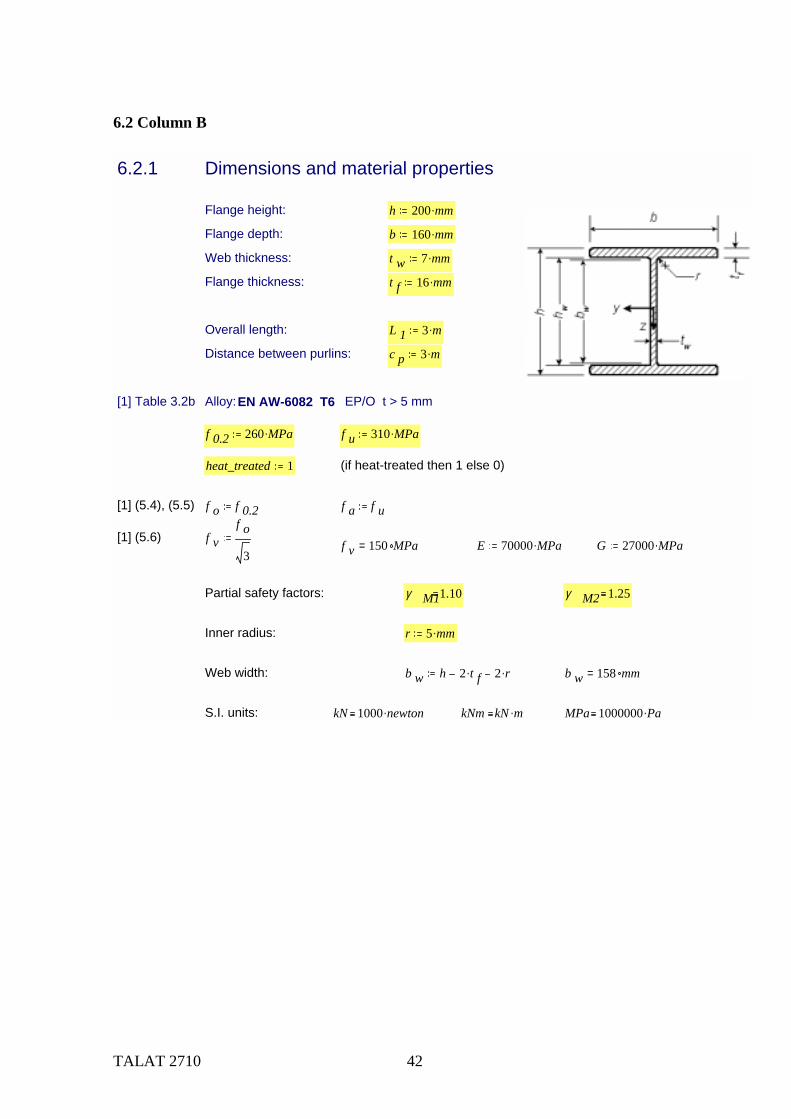
6.2.1 Dimensions and material properties
Flange height: h 200 mm.
Flange depth: b 160 mm.
Web thickness: t w 7 mm.
Flange thickness: t f 16 mm.
Overall length: L 1 3 m.
Distance between purlins: c p 3 m.
[1] Table 3.2b Alloy: EN AW-6082 T6 EP/O t > 5 mm
f 0.2 260 MPa. f u 310 MPa.
heat_treated 1 (if heat-treated then 1 else 0)
[1] (5.4), (5.5) f o f 0.2 f a f u
[1] (5.6) f vf o
3f v 150 MPa= E 70000 MPa. G 27000 MPa.
Partial safety factors: γ M11.10 γ M2 1.25
Inner radius: r 5 mm.
Web width: b w h 2 t f. 2 r. b w 158 mm=
S.I. units: kN 1000 newton. kNm kN m. MPa 1000000 Pa.
TALAT 2710 43
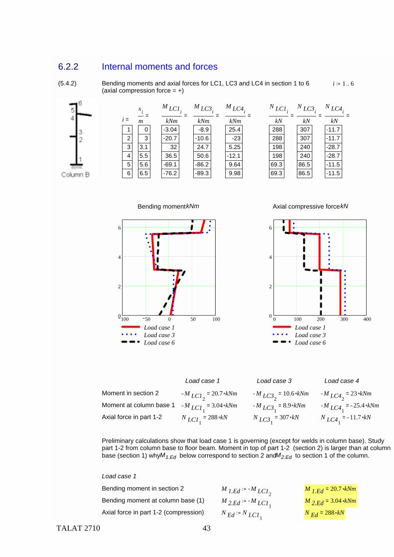
6.2.2 Internal moments and forces
(5.4.2) Bending moments and axial forces for LC1, LC3 and LC4 in section 1 to 6(axial compression force = +)
i 1 6..
xi
m03
3.15.55.66.5
=M LC1i
kNm-3.04-20.7
3236.5
-69.1-76.2
=M LC3i
kNm-8.9
-10.624.750.6
-86.2-89.3
=M LC4i
kNm25.4-23
5.25-12.19.649.98
=N LC1i
kN288288198198
69.369.3
=N LC3i
kN307307240240
86.586.5
=N LC4i
kN-11.7-11.7-28.7-28.7-11.5-11.5
=i123456
=
Bending moment kNm Axial compressive force kN
100 50 0 50 1000
2
4
6
Load case 1Load case 3Load case 6
0 100 200 300 4000
2
4
6
Load case 1Load case 3Load case 6
Load case 1 Load case 3 Load case 4
Moment in section 2 M LC1220.7 kNm= M LC32
10.6 kNm= M LC4223 kNm=
Moment at column base 1 M LC113.04 kNm= M LC31
8.9 kNm= M LC4125.4 kNm=
Axial force in part 1-2 N LC11288 kN= N LC31
307 kN= N LC4111.7 kN=
Preliminary calculations show that load case 1 is governing (except for welds in column base). Study part 1-2 from column base to floor beam. Moment in top of part 1-2 (section 2) is larger than at column base (section 1) why M1.Ed below correspond to section 2 and M2.Ed to section 1 of the column.
Load case 1
Bending moment in section 2 M 1.Ed M LC12M 1.Ed 20.7 kNm=
Bending moment at column base (1) M 2.Ed M LC11M 2.Ed 3.04 kNm=
Axial force in part 1-2 (compression) N Ed N LC11N Ed 288 kN=
TALAT 2710 44
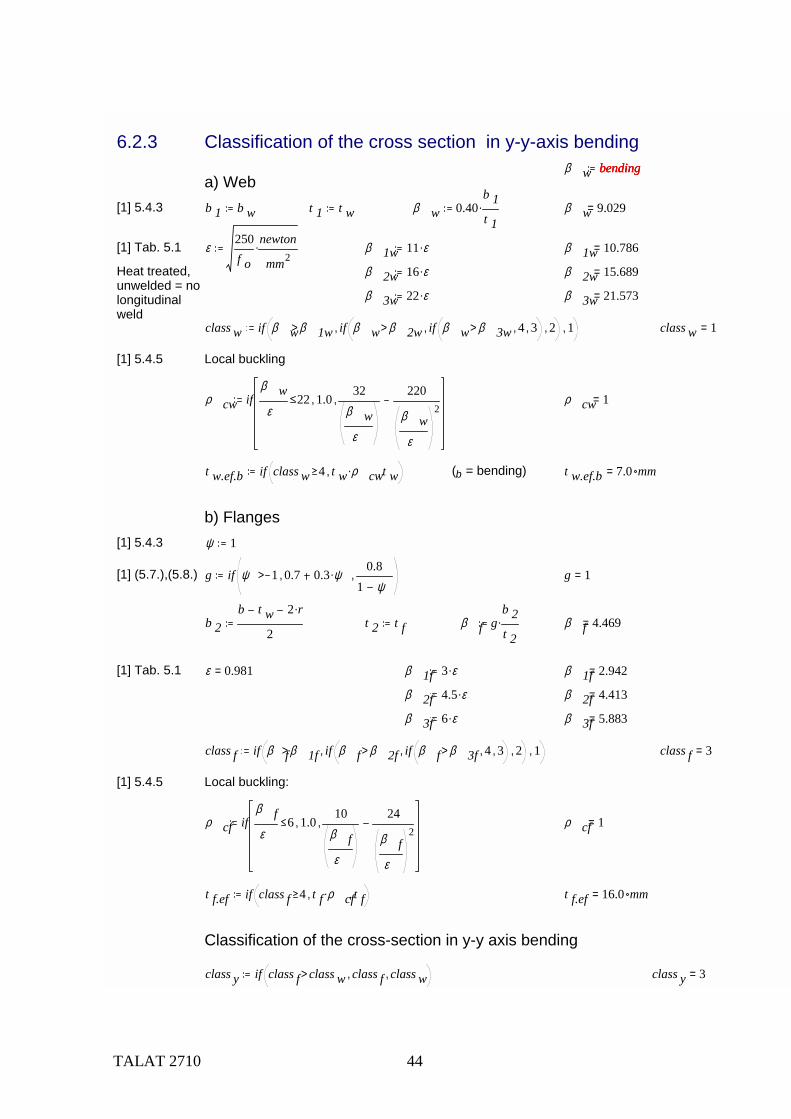
6.2.3 Classification of the cross section in y-y-axis bending β w bendingbendingbending
a) Web[1] 5.4.3 b 1 b w t 1 t w β w 0.40
b 1t 1
. β w 9.029=
[1] Tab. 5.1 ε250f o
newton
mm2. β 1w 11 ε. β 1w 10.786=
Heat treated,unwelded = no longitudinalweld
β 2w 16 ε. β 2w 15.689=
β 3w 22 ε. β 3w 21.573=
class w if β wβ 1w> if β w β 2w> if β w β 3w> 4, 3,, 2,, 1, class w 1=
[1] 5.4.5 Local buckling
ρ cw ifβ w
ε22 1.0,
32β w
ε
220
β wε
2, ρ cw 1=
t w.ef.b if class w 4 t w ρ cw., t w, (b = bending) t w.ef.b 7.0 mm=
b) Flanges[1] 5.4.3 ψ 1
[1] (5.7.),(5.8.) g if ψ 1> 0.7 0.3 ψ.,0.8
1 ψ, g 1=
b 2b t w 2 r.
2t 2 t f β f g
b 2t 2
. β f 4.469=
[1] Tab. 5.1 ε 0.981= β 1f 3 ε. β 1f 2.942=
β 2f 4.5 ε. β 2f 4.413=
β 3f 6 ε. β 3f 5.883=
class f if β fβ 1f> if β f β 2f> if β f β 3f> 4, 3,, 2,, 1, class f 3=
[1] 5.4.5 Local buckling:
ρ cf ifβ fε
6 1.0,10
β fε
24
β fε
2, ρ cf 1=
t f.ef if class f 4 t f ρ cf., t f, t f.ef 16.0 mm=
Classification of the cross-section in y-y axis bending
class y if class f class w> class f, class w, class y 3=
TALAT 2710 45
6.2.4 Classification of the cross section in z-z-axis bending
Cross section class of web: No bending stresses class w 1
Cross section class for flanges: According to above class f 3=
class z if class f class w> class f, class w, class z 3=
6.2.5 Classification of the cross section in axial compression
β wc compressioncompressioncompressiona) Webb 1 b w t 1 t w β wc
b 1t 1
β wc 22.571=
[1] Tab. 5.1 β 1w 10.786=
β 2w 15.689=
β 3w 21.573=
class wc if β wcβ 1w> if β wc β 2w> if β wc β 3w> 4, 3,, 2,, 1, class wc 4=
[1] 5.4.5 Local buckling
ρ cw ifβ wc
ε22 1.0,
32β wc
ε
220
β wcε
2, ρ cw 0.975=
t w.ef if class wc 4 t w ρ cw., t w, t w 7 mm= t w.ef 6.8 mm=
b) FlangesSame as in bending t f.ef 16.0 mm= class f 3=
Classification of the total cross-section in axial compressionclass c if class f class wc> class f, class wc, class c 4=
6.2.6. Welds[1] 5.5[1] Tab. 5.2 HAZ softening factor at column ends
ρ haz 0.65
TALAT 2710 46
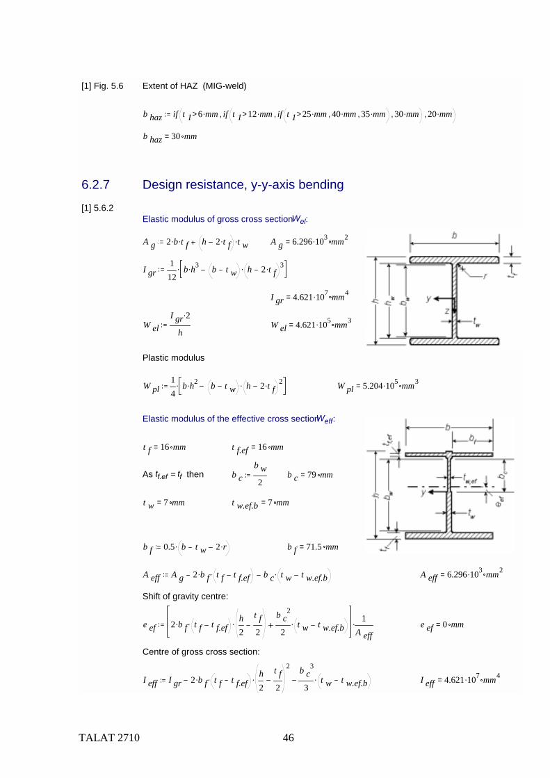
[1] Fig. 5.6 Extent of HAZ (MIG-weld)
b haz if t 1 6 mm.> if t 1 12 mm.> if t 1 25 mm.> 40 mm., 35 mm.,, 30 mm.,, 20 mm.,
b haz 30 mm=
6.2.7 Design resistance, y-y-axis bending
[1] 5.6.2Elastic modulus of gross cross section Wel:
A g 2 b. t f. h 2 t f. t w. A g 6.296 103. mm2=
I gr112
b h3. b t w h 2 t f. 3..
I gr 4.621 107. mm4=
W elI gr 2.
hW el 4.621 105. mm3=
Plastic modulus
W pl14
b h2. b t w h 2 t f. 2.. W pl 5.204 105. mm3=
Elastic modulus of the effective cross section Weff:
t f 16 mm= t f.ef 16 mm=
As tf.ef = tf then b cb w2
b c 79 mm=
t w 7 mm= t w.ef.b 7 mm=
b f 0.5 b t w 2 r.. b f 71.5 mm=
A eff A g 2 b f. t f t f.ef. b c t w t w.ef.b. A eff 6.296 103. mm2=
Shift of gravity centre:
e ef 2 b f. t f t f.ef. h2
t f2
.b c
2
2t w t w.ef.b. 1
A eff. e ef 0 mm=
Centre of gross cross section:
I eff I gr 2 b f. t f t f.ef. h2
t f2
2
.b c
3
3t w t w.ef.b. I eff 4.621 107. mm4=
TALAT 2710 47
Centre of effective gross section:
I eff I eff e ef2 A eff. I eff 4.621 107. mm4=
W effI eff
h2
e ef
W eff 4.621 105. mm3=
[1] Tab. 5.3 Shape factor α
- for welded, class 1 or 2 cross-sections:
α 1.2.wW plW el
α 1.2.w 1.126=
- for welded, class 3 cross-sections:
[1] (5.16) α 3.ww 1β 3w β w
β 3w β 2w
W pl W elW el
. α 3.ww 1.269=
[1] (5.16) α 3.wf 1β 3f β f
β 3f β 2f
W pl W elW el
. α 3.wf 1.121=
β, β2, β3 are the slenderness parameter and the limiting values for the most critical element in the cross-section, so it is the smaller value of α3.ww and α3.wf
α 3.w if α 3.ww α 3.wf α 3.ww, α 3.wf, α 3.w 1.121=
- for welded, class 4 cross-sections: α 4.wW effW el
α 4.w 1=
class y 3=
α y if class y 2> if class y 3> α 4.w, α 3.w,, α 1.2.w, α y 1.121=
Design moment of resistance of the cross section Mc,Rd
[1] (5.14) M y.Rdf o α y. W el.
γ M1M y.Rd 122.5 kNm=
6.2.8 Design resistance, z-z-axis bending
Cross section class class z 3=
Gross cross section: I z 2t f b3.
12. I z 1.092 107. mm4=
Effective cross section: I z.ef 2t f.ef b3.
12. I z.ef 1.092 107. mm4=
Section moduli: W zI z 2.
bW z.ef
I z.ef 2.
b
TALAT 2710 48
Shape factor: α zW z
W z.efα z 1=
Bending resistance: M z.Rdf o α z. W z.
γ M1M z.Rd 32.272 kNm=
6.2.9 Axial force resistance, y-y buckling
[1] 5.8.4 Cross section area of gross cross section Agr
A gr b h. b t w h 2 t f.. A gr 6.296 103. mm2=
Cross section area of effective cross section Aef
A ef A gr 2 b f. t f t f.ef. b w t w t w.ef. A ef 6.268 103. mm2=
( t f 16 mm= t w 7 mm= 2 b 2. 143 mm= t w.ef 6.825 mm= t w.ef 6.825 mm= )
Effective cross section factor ηA efA gr
η 0.996=
Second moment of area of gross cross section Iy:
I y212
b. t f3. 2 b. t f.
h t f2
2
. 112
h 2 t f. 3. t w.
[1] Table 5.7 Buckling length factor K y 1.5 L 1 3 m= l yc K y L 1. l yc 4.5 m=
Case 5.See also 6.2.11 below Buckling load N cr
π2 E. I y.
l yc2
N cr 1.577 103. kN=
[1] 5.8.4.1 Slenderness parameter λ yA gr η. f o.
N crλ y 1.017=
[1] Table 5.6 α if heat_treated 1 0.2, 0.32,( ) α 0.2=
λ o if heat_treated 1 0.1, 0,( ) λ o 0.1=
φ 0.5 1 α λ y λ o. λ y2. φ 1.109=
χ y1
φ φ 2 λ y2
χ y 0.645=
[1] Table 5.5 Symmetric profile k 1 1
[1] Table 5.5 No longitudinal welds k 2 1
Axial force resistance N y.Rd χ yη. k 1. k 2.f o
γ M1. A gr. N y.Rd 955.708 kN=
TALAT 2710 49
6.2.10 Axial force resistance, z-z axis buckling
[1] Table 5.5 Buckling length factor K 1 L 1 3 m= K L 1. 3 m=
Case 3Buckling load N cr
π2 E. I z.
K L 1. 2N cr 838.5 kN=
[1] 5.8.4.1 Slenderness factor λ zA gr η. f o.
N crλ z 1.394=
[1] Table 5.6 α if heat_treated 1 0.2, 0.32,( ) α 0.2=
λ o if heat_treated 1 0.1, 0,( ) λ o 0.1=
[1] 5.8.4.1 φ 0.5 1 α λ z λ o. λ z2. φ 1.601=
χ z1
φ φ 2 λ z2
χ z 0.419=
k 1 1[1] Table 5.5 Symmetric profile
k 2 1[1] Table 5.5 No longitudinal welds
[1] 5.8.4.1 Axial load resistance N z.Rd χ zη. k 1. k 2.f o
γ M1. A gr. N z.Rd 620.192 kN=
(6.2.9) Compare y-y axis buckling N y.Rd 955.708 kN=
and without column buckling N Rd ηf o
γ M1. A gr. N Rd 1.482 103. kN=
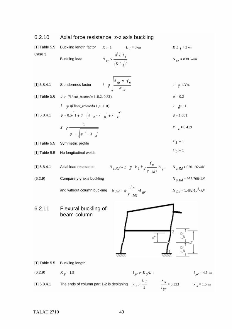
6.2.11 Flexural buckling ofbeam-column
[1] Table 5.5 Buckling length
(6.2.9) K y 1.5= l yc K y L 1. l yc 4.5 m=
[1] 5.8.4.1 The ends of column part 1-2 is designing x sL 12
x sl yc
0.333= x s 1.5 m=
TALAT 2710 50
[1] 5.9.4.5 HAZ reduction factors ρ haz 0.65=
[1] (5.51) ω 0 ρ hazf u
γ M2.
γ M1f o
. ω 0 if ω 0 1> 1, ω 0, ω 0 0.682=
[1] (5.49) ω xω 0
χ y 1 χ y sinπ x s.
l yc.
ω x 0.716=
Exponents in interaction formulae
[1] (5.42c) ξ 0 α y2 ξ 0 if ξ 0 1< 1, ξ 0, ξ 0 1.258=
[1] 5.9.4.2 ξ yc ξ 0 χ y. ξ yc if ξ yc 0.8< 0.8, ξ yc, ξ yc 0.811=
Flexural buckling check
Bending moment M y.Ed M 1.Ed M y.Ed 20.7 kNm=
[1] 5.4.4 U yN Ed
χ zω x. N Rd.
ξ yc M y.Edω 0 M y.Rd.
U y 0.952=
or with simplified exponents
U ysN Ed
χ zω x. N Rd.
0.8 M y.Edω 0 M y.Rd.
1.0
U ys 0.955=
6.2.12 Lateral-torsional buckling of beam-column
[1] 5.9.4.3
[1] Figure J.2 Varping constant: I wh t f
2 I z.
4I w 9.245 1010. mm6=
Torsional constant: I t2 b. t f
3. h t w3.
3I t 4.598 105. mm4=
L L 1 W y W el W y 4.621 105. mm3=
[1] H.1.2 Moment relation ψM 2.EdM 1.Ed ψ 0.147=
[1] H.1.2(6) C1 - constant C 1 1.88 1.4 ψ. 0.52 ψ 2. C 1 1.686=
TALAT 2710 51
Shear modulus G 2.7 104. MPa=
[1] H.1.3(3) M crC 1 π2. E. I z.
L2
I wI z
L2 G. I t.
π 2 E. I z.. M cr 215.593 kN m.=
[1] 5.6.6.3(3) λ LTα y W y. f o.
M crλ LT 0.791=
[1] 5.6.6.3(2) α LT if class z 2> 0.2, 0.1, α LT 0.2=
λ 0LT if class z 2> 0.4, 0.6, λ 0LT 0.4=
[1] 5.6.6.3(1) φ LT 0.5 1 α LT λ LT λ 0LT. λ LT2. φ LT 0.852=
χ LT1
φ LT φ LT2 λ LT
2χ LT 0.856=
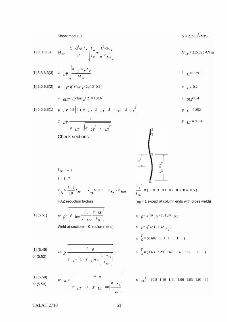
Check sections
l zc L 1
i 1 7..
x si
i 210
l zc. x s10 m. x s2
b hazx sl zc
T0 0.01 0.1 0.2 0.3 0.4 0.5( )=
HAZ reduction factors (ω0 = 1 except at column ends with cross welds)
[1] (5.51) ω 0iρ haz
f uγ M2
.γ M1
f o. ω 0i
if ω 0i1> 1, ω 0i
,
Weld at section i = 0 (column end) ω 0iif i 1> 1, ω 0i
,
ω 0T 0.682 1 1 1 1 1 1( )=
[1] (5.49) ω xω 0
χ z 1 χ z sinπ x s.
l zc.
ω xT 1.63 2.29 1.67 1.32 1.12 1.03 1( )=
or (5.52)
[1] (5.50) ω xLTω 0
χ LT 1 χ LT sinπ x s.
l zc.
ω xLTT 0.8 1.16 1.11 1.06 1.03 1.01 1( )=
or (5.53)
TALAT 2710 52
[1] (5.42a) η 0 α z2 α y
2. η 0 if η 0 1< 1, if η 0 2> 2, η 0,, η 0 1.258=
[1] (5.42b) γ 0 α z2 γ 0 if γ 0 1< 1, if γ 0 2> 2, γ 0,, γ 0 1=
[1] (5.42c) ξ 0 α y2 ξ 0 if ξ 0 1< 1, ξ 0, ξ 0 1.258=
[1] 5.9.4.3 η c η 0 χ z. η c if η c 0.8< 0.8, η c, χ y 0.645= η c 0.8=
[1] 5.9.4.3 γ c γ 0 χ z 0.419= γ c 1=
[1] 5.9.4.3 ξ zc ξ 0 χ z. ξ zc if ξ zc 0.8< 0.8, ξ zc, ξ zc 0.8=
Lateral-torsional buckling check
Bending moment in section xs M y.Ed M 1.Ed M 1.Ed M 2.Edx sl zc
.
M y.EdM 1.Ed
T1 0.991 0.915 0.829 0.744 0.659 0.573( )=
M z.Ed 0 kNm.
[1] (5.43) U LTN Ed
χ zω x. N Rd.
η c M y.Edχ LT ω xLT. M y.Rd.
γ c M z.Edω 0 M z.Rd.
ξ zc
U LTT 0.614 0.448 0.522 0.589 0.636 0.658 0.655( )=
or with simplified exponents
U LTsN Ed
χ zω x. N Rd.
0.8 M y.Edχ LT ω xLT. M y.Rd.
1 M z.Edω 0 M z.Rd.
0.8
U LTsT 0.614 0.448 0.522 0.589 0.636 0.658 0.655( )=
Max utilisation, lateral-torsional buckling U z.max max U LT U z.max 0.658=
Compare utilisation, flexural buckling U y 0.952=
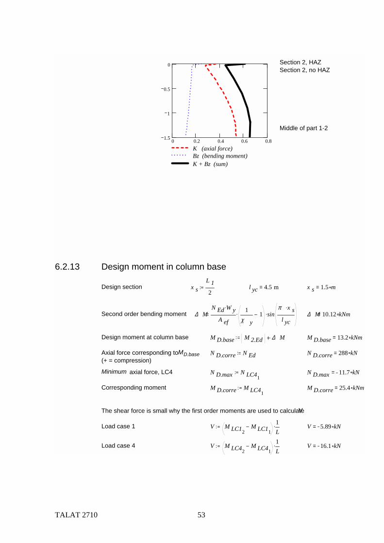
KN Ed
χ zω x. N Rd.
η c
B zM y.Ed
χ LT ω xLT. M y.Rd.
γ c
TALAT 2710 53
0 0.2 0.4 0.6 0.81.5
1
0.5
0
K (axial force)Bz (bending moment)K + Bz (sum)
Section 2, HAZSection 2, no HAZ
Middle of part 1-2
6.2.13 Design moment in column base
Design section x sL 12
l yc 4.5 m= x s 1.5 m=
Second order bending moment ∆ MN Ed W y.
A ef
1χ y
1. sinπ x s.
l yc. ∆ M 10.12 kNm=
Design moment at column base M D.base M 2.Ed ∆ M M D.base 13.2 kNm=
Axial force corresponding to MD.base N D.corre N Ed N D.corre 288 kN=(+ = compression)
Minimum axial force, LC4 N D.max N LC41N D.max 11.7 kN=
Corresponding moment M D.corre M LC41M D.corre 25.4 kNm=
The shear force is small why the first order moments are used to calculate V
Load case 1 V M LC12M LC11
1L
. V 5.89 kN=
Load case 4 V M LC42M LC41
1L
. V 16.1 kN=
TALAT 2710 54
6.2.14 DeflectionsTo calculate the fictive second moment of area I fic, the bending moment in the serviceability limit state is supposed to be half the maximum bending moment at the ultimate limit state.
[1] 4.2.4 σ gr0.5 M 1.Ed.
I gr
h2
. I gr 4.621 107. mm4= σ gr 22 MPa=
Allowing for a reduced stress level, Ific may be used constant along the beam.
[1] (4.2) I fic I grσ grf o
I gr I eff. I fic 4.621 107. mm4=
I if class y 4 I fic, I gr, class y 3= I 4.621 107. mm4=
δ 1 0 mm. δ 1 0 mm=
δ 2 4.7 mm. δ 2 4.7 mm=
Pre-camber δ 0 0 mm.
δ max δ 1 δ 2 δ 0 δ max 4.7 mm=
Limit horizontal deformation for building frame with h building 6.5 m.
δ limith building
300δ limit 22 mm=
Check if δ max δ limit< "OK!", "Not OK!", Check "OK!"=
6.2.15 SummaryM 1.Ed 21 kNm= M y.Rd 122 kNm= ω 01
0.682=M 1.Ed
ω 01M y.Rd.
0.248=
ω x11.629=N Ed 288 kN= N y.Rd 955.7 kN=
N Edχ yω x1
. N y.Rd.0.287=
χ y 0.645=
Utilisation, flexural buckling - HAZ at column base U y 0.952=
Utilisation, lateral-torsional buckling U z.max 0.658=
δ limit 21.7 mm= δ max 4.7 mm=δ max
δ limit0.217=
Effective second moment of area I fic 4.621 107. mm4=
Cross section h 200 mm= b 160 mm= t w 7 mm= t f 16 mm= A gr 6.296 103. mm2=

TALAT 2710 55
6.3 Column C Comment: To reduce the extent of this example the check of column C is left out. It is given the same cross section as column A.
TALAT 2710 56
6.4 Floor Beam D
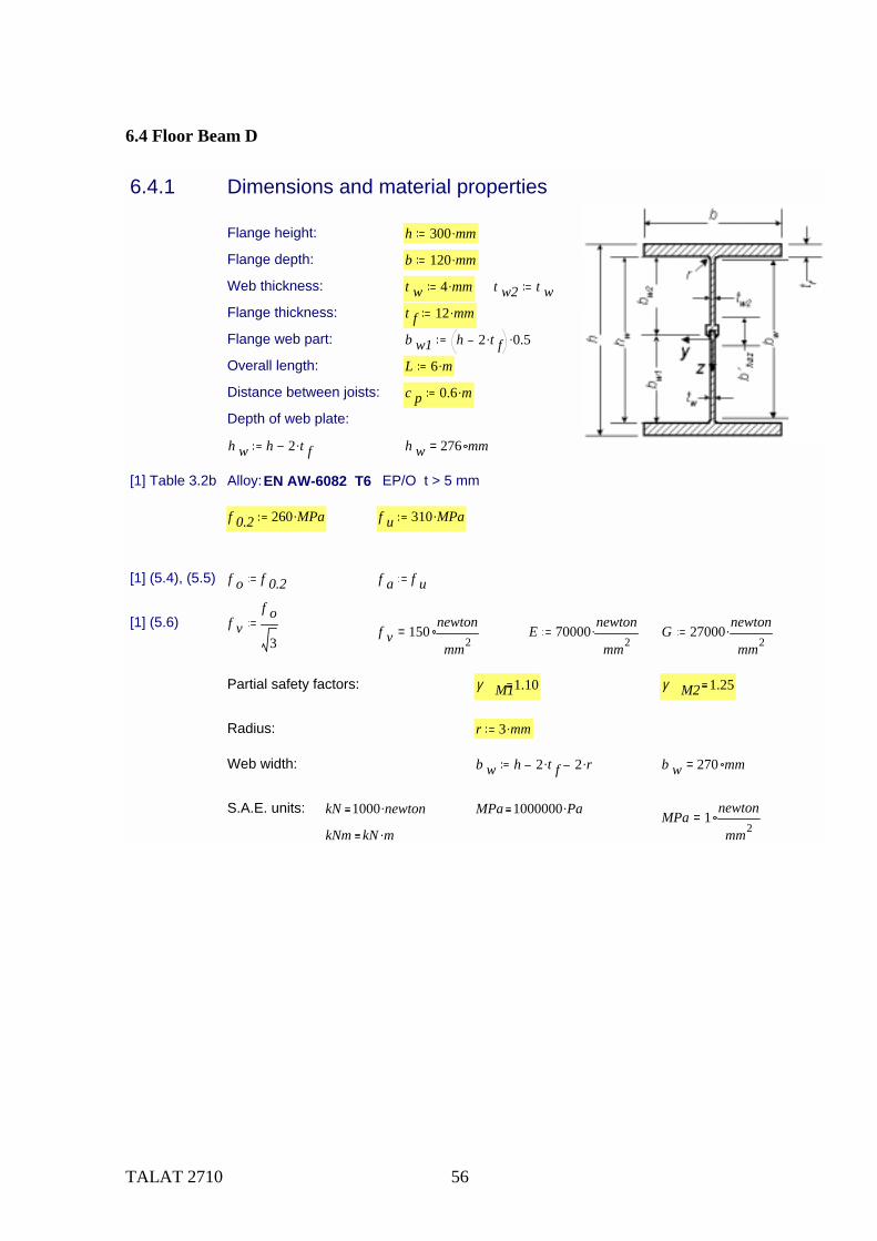
6.4.1 Dimensions and material properties
Flange height: h 300 mm.
Flange depth: b 120 mm.
Web thickness: t w 4 mm. t w2 t wFlange thickness: t f 12 mm.
Flange web part: b w1 h 2 t f. 0.5.
Overall length: L 6 m.
Distance between joists: c p 0.6 m.
Depth of web plate:
h w h 2 t f. h w 276 mm=
[1] Table 3.2b Alloy: EN AW-6082 T6 EP/O t > 5 mm
f 0.2 260 MPa. f u 310 MPa.
[1] (5.4), (5.5) f o f 0.2 f a f u
[1] (5.6) f vf o
3f v 150
newton
mm2= E 70000
newton
mm2. G 27000
newton
mm2.
Partial safety factors: γ M11.10 γ M2 1.25
Radius: r 3 mm.
Web width: b w h 2 t f. 2 r. b w 270 mm=
S.A.E. units: kN 1000 newton. MPa 1000000 Pa.MPa 1
newton
mm2=
kNm kN m.
TALAT 2710 57
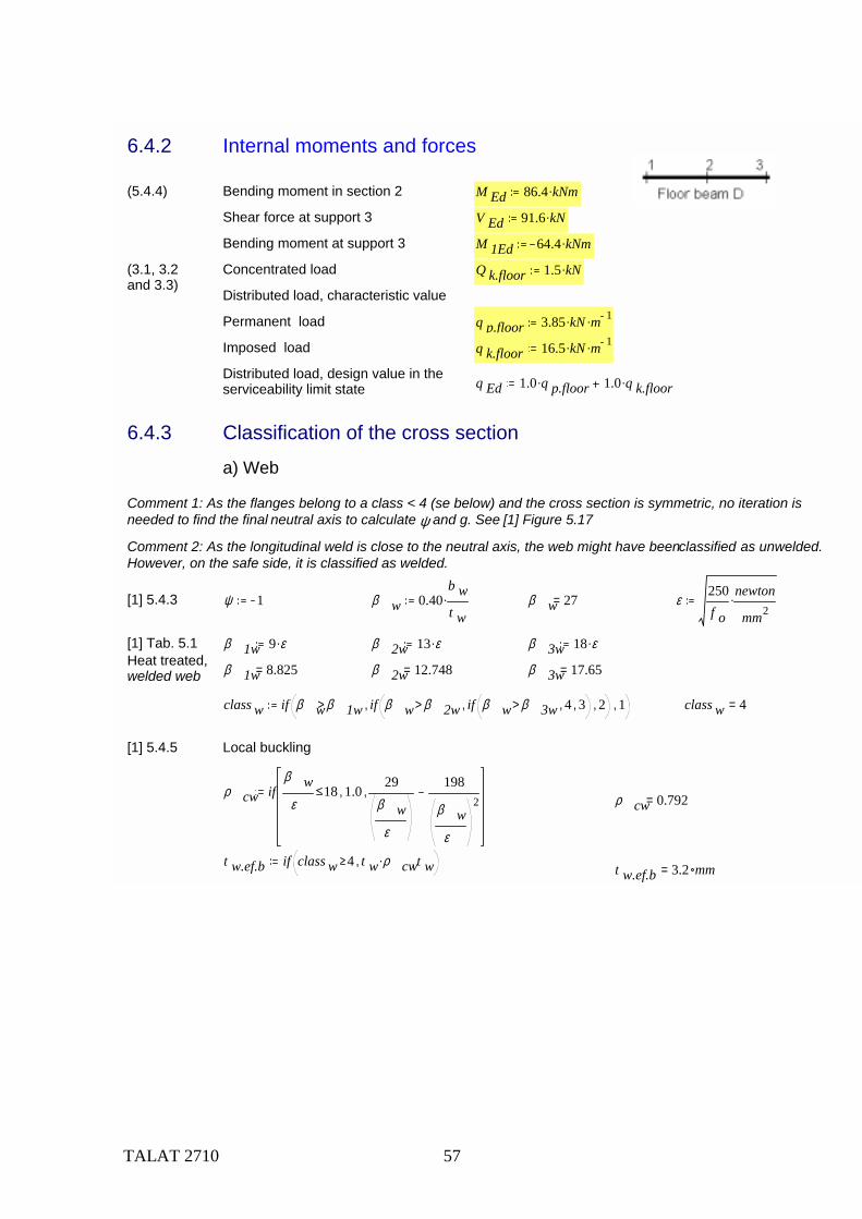
6.4.2 Internal moments and forces
(5.4.4) Bending moment in section 2 M Ed 86.4 kNm.
Shear force at support 3 V Ed 91.6 kN.
Bending moment at support 3 M 1Ed 64.4 kNm.
(3.1, 3.2and 3.3)
Concentrated load Q k.floor 1.5 kN.
Distributed load, characteristic value
Permanent load q p.floor 3.85 kN. m 1.
Imposed load q k.floor 16.5 kN. m 1.
Distributed load, design value in theserviceability limit state q Ed 1.0 q p.floor. 1.0 q k.floor.
6.4.3 Classification of the cross section
a) Web
Comment 1: As the flanges belong to a class < 4 (se below) and the cross section is symmetric, no iteration is needed to find the final neutral axis to calculate ψ and g. See [1] Figure 5.17
Comment 2: As the longitudinal weld is close to the neutral axis, the web might have been classified as unwelded. However, on the safe side, it is classified as welded.
[1] 5.4.3 ψ 1 β w 0.40b wt w
. β w 27= ε250f o
newton
mm2.
[1] Tab. 5.1 β 1w 9 ε. β 2w 13 ε. β 3w 18 ε.Heat treated,welded web β 1w 8.825= β 2w 12.748= β 3w 17.65=
class w if β wβ 1w> if β w β 2w> if β w β 3w> 4, 3,, 2,, 1, class w 4=
[1] 5.4.5 Local buckling
ρ cw ifβ w
ε18 1.0,
29β w
ε
198
β wε
2, ρ cw 0.792=
t w.ef.b if class w 4 t w ρ cw., t w, t w.ef.b 3.2 mm=
TALAT 2710 58
[1] 5.4.3 b) Flanges
[1] (5.7.),(5.8.) ψ 1 g 1 β f gb t w 2 r.
2 t f.. β f 4.583=
Heat treated, unwelded flange
[1] Tab. 5.1 β 1f 3 ε. β 2f 4.5 ε. β 3f 6 ε.
β 1f 2.942= β 2f 4.413= β 3f 5.883=
class f if β fβ 1f> if β f β 2f> if β f β 3f> 4, 3,, 2,, 1, class f 3=
[1] 5.4.5 Local buckling:
ρ cf ifβ fε
6 1.0,10
β fε
24
β fε
2, ρ cf 1=
t f.ef if class f 4 t f ρ cf., t f, t f.ef 12.0 mm=
Classification of the total cross-section:
class if class f class w> class f, class w, class 4=
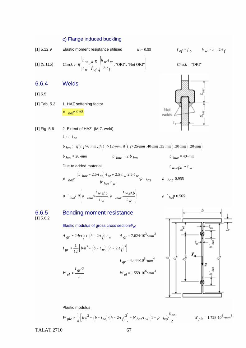
c) Flange induced buckling
[1] 5.12.9 Elastic moment resistance utilised k 0.55 f of f o
[1] (5.115) check ifh wt w
k E.
f of
h w t w.
b t f..< "OK!", "Not OK!", check "OK!"=
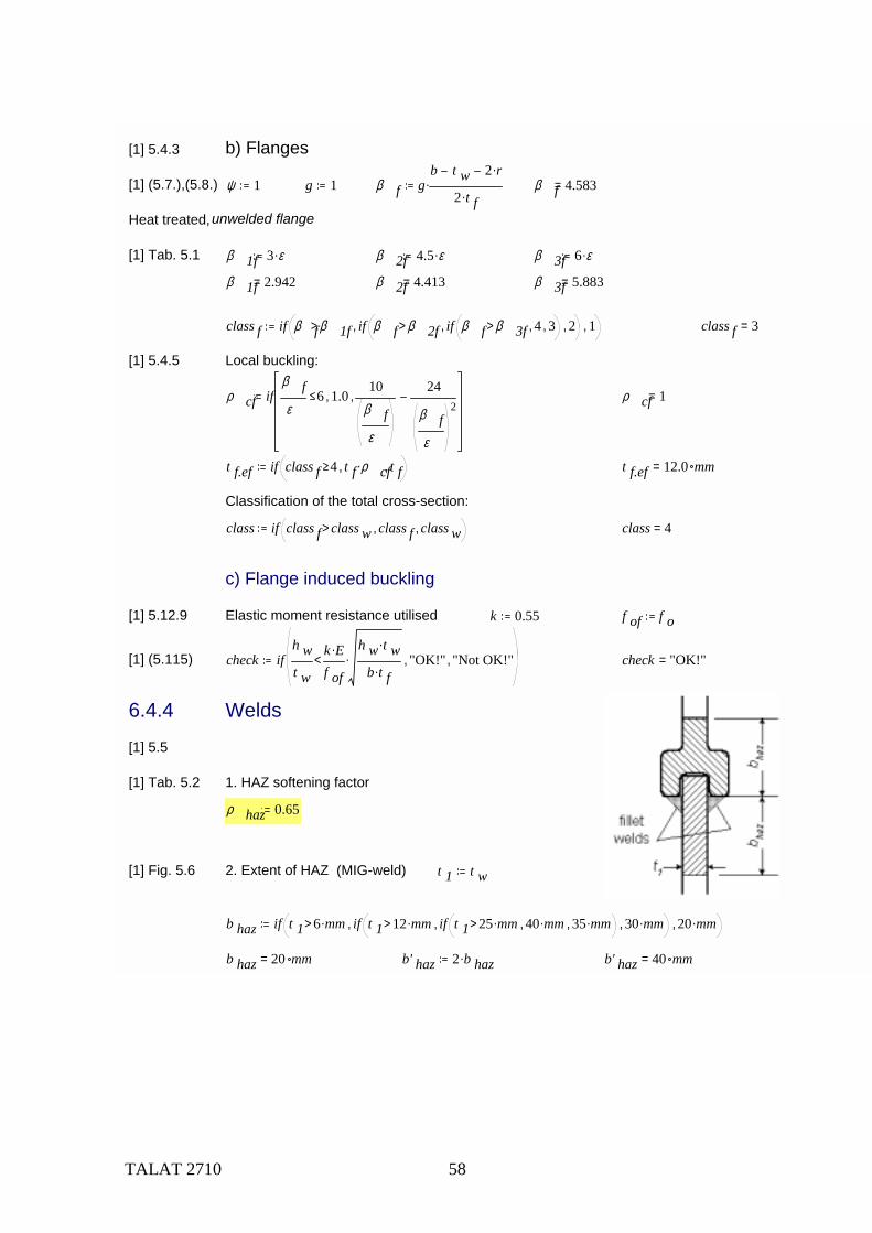
6.4.4 Welds
[1] 5.5
[1] Tab. 5.2 1. HAZ softening factor
ρ haz 0.65
[1] Fig. 5.6 2. Extent of HAZ (MIG-weld) t 1 t w
b haz if t 1 6 mm.> if t 1 12 mm.> if t 1 25 mm.> 40 mm., 35 mm.,, 30 mm.,, 20 mm.,
b haz 20 mm= b' haz 2 b haz. b' haz 40 mm=
TALAT 2710 59
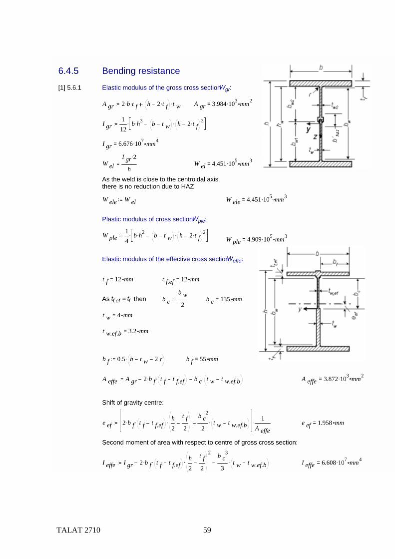
6.4.5 Bending resistance
[1] 5.6.1 Elastic modulus of the gross cross section Wgr:
A gr 2 b. t f. h 2 t f. t w. A gr 3.984 103. mm2=
I gr112
b h3. b t w h 2 t f. 3..
I gr 6.676 107. mm4=
W elI gr 2.
hW el 4.451 105. mm3=
As the weld is close to the centroidal axisthere is no reduction due to HAZ
W ele W el W ele 4.451 105. mm3=
Plastic modulus of cross section Wple:
W ple14
b h2. b t w h 2 t f. 2..W ple 4.909 105. mm3=
Elastic modulus of the effective cross section Weffe:
t f 12 mm= t f.ef 12 mm=
As tf.ef = tf then b cb w2
b c 135 mm=
t w 4 mm=
t w.ef.b 3.2 mm=
b f 0.5 b t w 2 r.. b f 55 mm=
A effe A gr 2 b f. t f t f.ef. b c t w t w.ef.b. A effe 3.872 103. mm2=
Shift of gravity centre:
e ef 2 b f. t f t f.ef. h2
t f2
.b c
2
2t w t w.ef.b. 1
A effe. e ef 1.958 mm=
Second moment of area with respect to centre of gross cross section:
I effe I gr 2 b f. t f t f.ef. h2
t f2
2
.b c
3
3t w t w.ef.b. I effe 6.608 107. mm4=
TALAT 2710 60
Second moment of area with respect to centre of effective gross section:
I effe I effe e ef2 A effe. I effe 6.607 107. mm4=
W effeI effe
h2
e ef
W effe 4.348 105. mm3=
[1] Tab. 5.3 Shape factor α
- for welded, class 1 or 2 cross-sections:
α 1.2.wW pleW el
α 1.2.w 1.103=
- for welded, class 3 cross-sections:
[1] (5.16) α 3.wwW eleW el
β 3w β wβ 3w β 2w
W ple W eleW el
. α 3.ww 0.804=
[1] (5.16) α 3.wfW eleW el
β 3f β fβ 3f β 2f
W ple W eleW el
. α 3.wf 1.091=
β, β2, β3 are the slenderness parameter and the limiting values for the most critical element in the cross-section, so it is the smaller value of α3.ww and α3.wf
α 3.w if α 3.ww α 3.wf α 3.ww, α 3.wf, α 3.w 0.804=
- for welded, class 4 cross-sections: α 4.wW effeW el
α 4.w 0.977=
class 4=
α if class 2> if class 3> α 4.w, α 3.w,, α 1.2.w, α 0.977=
Design moment of resistance of the cross section Mc,Rd
[1] (5.14) M c.Rdf o α. W el.
γ M1M c.Rd 102.8 kNm=
TALAT 2710 61
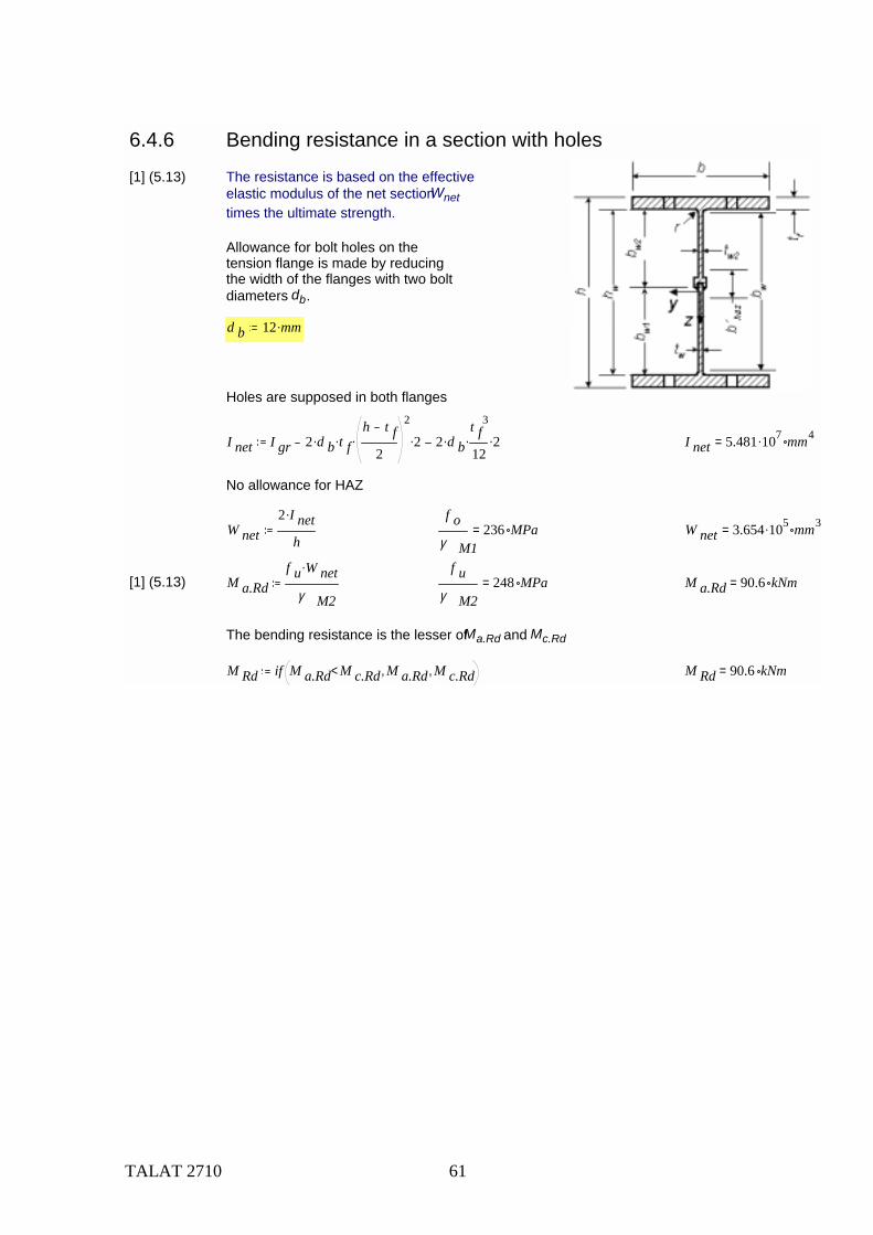
6.4.6 Bending resistance in a section with holes
[1] (5.13) The resistance is based on the effectiveelastic modulus of the net section Wnet times the ultimate strength.
Allowance for bolt holes on thetension flange is made by reducingthe width of the flanges with two boltdiameters db.
d b 12 mm.
Holes are supposed in both flanges
I net I gr 2 d b. t f.h t f
2
2
. 2. 2 d b.t f
3
12. 2. I net 5.481 107. mm4=
No allowance for HAZ
W net2 I net.
h
f oγ M1
236 MPa= W net 3.654 105. mm3=
[1] (5.13) M a.Rdf u W net.
γ M2
f uγ M2
248 MPa= M a.Rd 90.6 kNm=
The bending resistance is the lesser of Ma.Rd and Mc.Rd
M Rd if M a.Rd M c.Rd< M a.Rd, M c.Rd, M Rd 90.6 kNm=
TALAT 2710 62
6.4.7 Shear force resistance
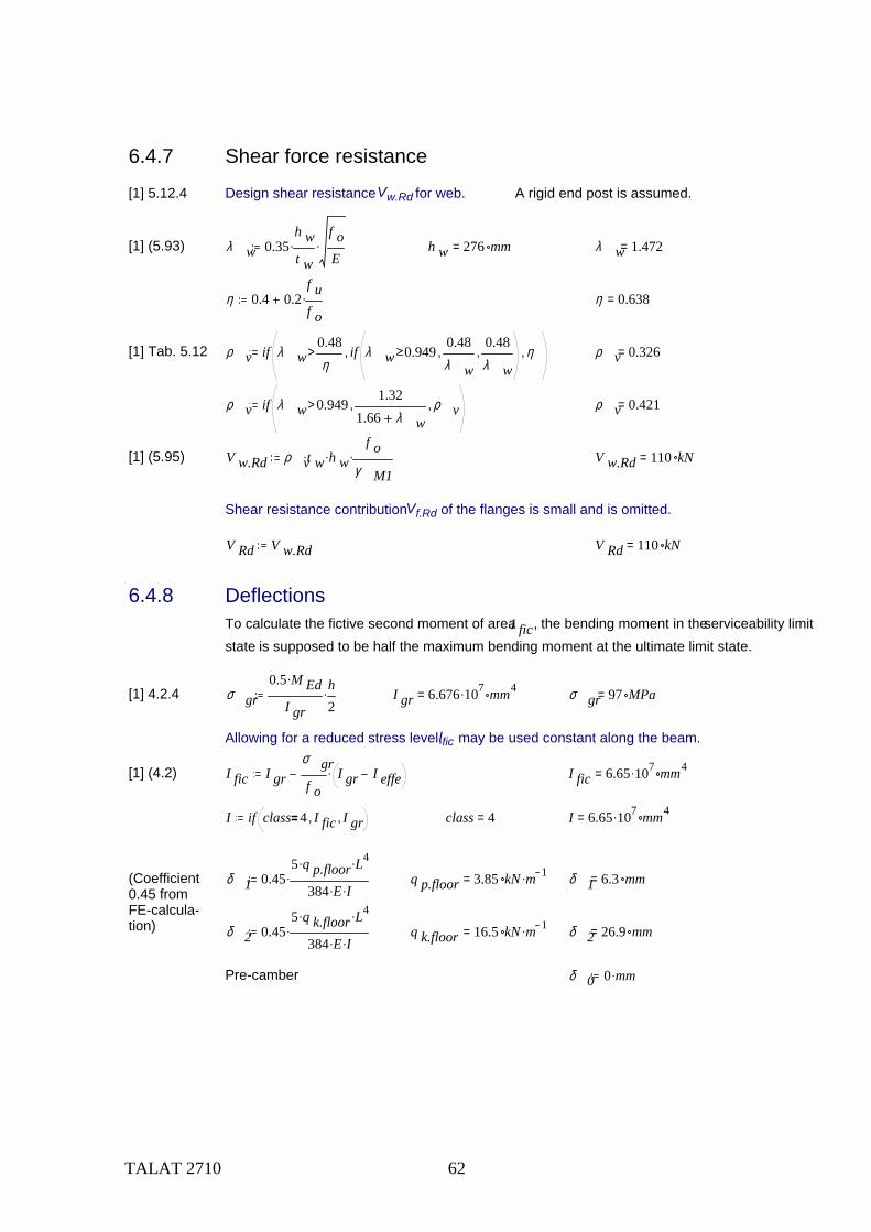
[1] 5.12.4 Design shear resistance Vw.Rd for web. A rigid end post is assumed.
[1] (5.93) λ w 0.35h wt w
.f oE
. h w 276 mm= λ w 1.472=
η 0.4 0.2f uf o
. η 0.638=
[1] Tab. 5.12 ρ v if λ w0.48η
> if λ w 0.9490.48λ w
,0.48λ w
,, η, ρ v 0.326=
ρ v if λ w 0.949>1.32
1.66 λ w, ρ v, ρ v 0.421=
[1] (5.95) V w.Rd ρ vt w. h w.f o
γ M1. V w.Rd 110 kN=
Shear resistance contribution Vf.Rd of the flanges is small and is omitted.
V Rd V w.Rd V Rd 110 kN=
6.4.8 DeflectionsTo calculate the fictive second moment of area I fic, the bending moment in the serviceability limit state is supposed to be half the maximum bending moment at the ultimate limit state.
[1] 4.2.4 σ gr0.5 M Ed.
I gr
h2
. I gr 6.676 107. mm4= σ gr 97 MPa=
Allowing for a reduced stress level, Ific may be used constant along the beam.
[1] (4.2) I fic I grσ grf o
I gr I effe. I fic 6.65 107. mm4=
I if class 4 I fic, I gr, class 4= I 6.65 107. mm4=
(Coefficient 0.45 from FE-calcula-tion)
δ 1 0.455 q p.floor. L4.
384 E. I.. q p.floor 3.85 kN m 1.= δ 1 6.3 mm=
δ 2 0.455 q k.floor. L4.
384 E. I.. q k.floor 16.5 kN m 1.= δ 2 26.9 mm=
Pre-camber δ 0 0 mm.
TALAT 2710 63
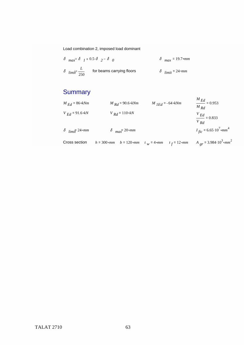
Load combination 2, imposed load dominant
δ max δ 1 0.5 δ 2. δ 0 δ max 19.7 mm=
δ limitL
250for beams carrying floors δ limit 24 mm=
SummaryM Ed 86 kNm= M Rd 90.6 kNm= M 1Ed 64 kNm=
M EdM Rd
0.953=
V Ed 91.6 kN= V Rd 110 kN= V EdV Rd
0.833=
δ limit 24 mm= δ max 20 mm= I fic 6.65 107. mm4=
Cross section h 300 mm= b 120 mm= t w 4 mm= t f 12 mm= A gr 3.984 103. mm2=

TALAT 2710 64
6.5 Roof Beam E Comment: To reduce the extent of this example the check of roof beam E is left out. It is given the same cross section as roof beam D.
TALAT 2710 65
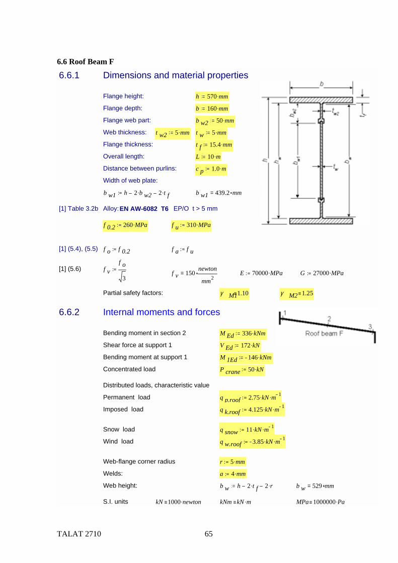
6.6 Roof Beam F
6.6.1 Dimensions and material properties
Flange height: h 570 mm.
Flange depth: b 160 mm.
Flange web part: b w2 50 mm.
Web thickness: t w2 5 mm. t w 5 mm.
Flange thickness: t f 15.4 mm.
Overall length: L 10 m.
Distance between purlins: c p 1.0 m.
Width of web plate:
b w1 h 2 b w2. 2 t f. b w1 439.2 mm=
[1] Table 3.2b Alloy: EN AW-6082 T6 EP/O t > 5 mm
f 0.2 260 MPa. f u 310 MPa.
[1] (5.4), (5.5) f o f 0.2 f a f u
[1] (5.6) f vf o
3f v 150
newton
mm2= E 70000 MPa. G 27000 MPa.
Partial safety factors: γ M11.10 γ M2 1.25
6.6.2 Internal moments and forces
Bending moment in section 2 M Ed 336 kNm.
Shear force at support 1 V Ed 172 kN.
Bending moment at support 1 M 1Ed 146 kNm.
Concentrated load P crane 50 kN.
Distributed loads, characteristic value
Permanent load q p.roof 2.75 kN. m 1.
Imposed load q k.roof 4.125 kN. m 1.
Snow load q snow 11 kN. m 1.
Wind load q w.roof 3.85 kN. m 1.
Web-flange corner radius r 5 mm.
Welds: a 4 mm.
Web height: b w h 2 t f. 2 r. b w 529 mm=
S.I. units kN 1000 newton. kNm kN m. MPa 1000000 Pa.
TALAT 2710 66
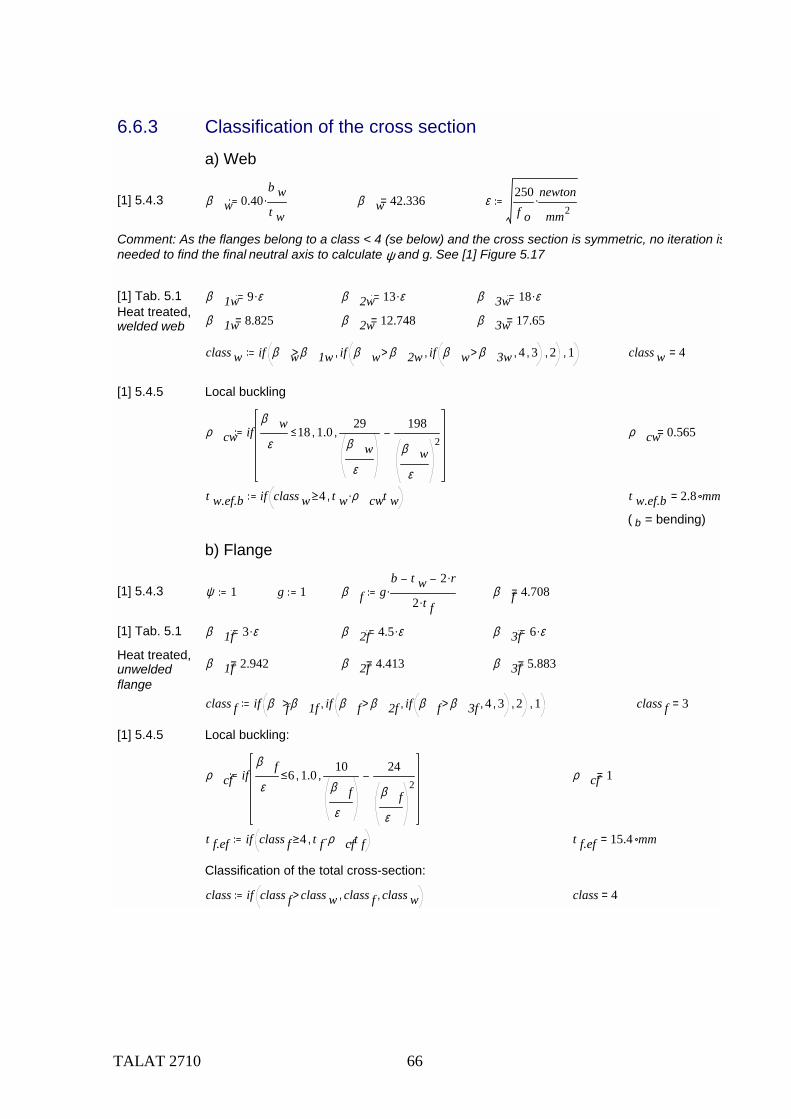
6.6.3 Classification of the cross section
a) Web
[1] 5.4.3 β w 0.40b wt w
. β w 42.336= ε250f o
newton
mm2.
Comment: As the flanges belong to a class < 4 (se below) and the cross section is symmetric, no iteration isneeded to find the final neutral axis to calculate ψ and g. See [1] Figure 5.17
[1] Tab. 5.1 β 1w 9 ε. β 2w 13 ε. β 3w 18 ε.Heat treated,welded web β 1w 8.825= β 2w 12.748= β 3w 17.65=
class w if β wβ 1w> if β w β 2w> if β w β 3w> 4, 3,, 2,, 1, class w 4=
[1] 5.4.5 Local buckling
ρ cw ifβ w
ε18 1.0,
29β w
ε
198
β wε
2, ρ cw 0.565=
t w.ef.b if class w 4 t w ρ cw., t w, t w.ef.b 2.8 mm=
( b = bending)
b) Flange
[1] 5.4.3 ψ 1 g 1 β f gb t w 2 r.
2 t f.. β f 4.708=
[1] Tab. 5.1 β 1f 3 ε. β 2f 4.5 ε. β 3f 6 ε.
Heat treated,unwelded flange
β 1f 2.942= β 2f 4.413= β 3f 5.883=
class f if β fβ 1f> if β f β 2f> if β f β 3f> 4, 3,, 2,, 1, class f 3=
[1] 5.4.5 Local buckling:
ρ cf ifβ fε
6 1.0,10
β fε
24
β fε
2, ρ cf 1=
t f.ef if class f 4 t f ρ cf., t f, t f.ef 15.4 mm=
Classification of the total cross-section:
class if class f class w> class f, class w, class 4=
TALAT 2710 67
c) Flange induced buckling
[1] 5.12.9 Elastic moment resistance utilised k 0.55 f of f o h w h 2 t f.
[1] (5.115) Check ifh wt w
k E.
f of
h w t w.
b t f..< "OK!", "Not OK!", Check "OK!"=
6.6.4 Welds
[1] 5.5
[1] Tab. 5.2 1. HAZ softening factor
ρ haz 0.65
[1] Fig. 5.6 2. Extent of HAZ (MIG-weld)
t 1 t w
b haz if t 1 6 mm.> if t 1 12 mm.> if t 1 25 mm.> 40 mm., 35 mm.,, 30 mm.,, 20 mm.,
b haz 20 mm= b' haz 2 b haz. b' haz 40 mm=
Due to added material: t w..ef.b t w
ρ hazb' haz 2.5 t w. t w. 2.5 t w. 2.5. t w.
b' haz t w. ρ haz. ρ haz 0.955=
ρ ´ haz if ρ hazt w.ef.b
t w< ρ haz,
t w.ef.bt w
, ρ ´ haz 0.565=
6.6.5 Bending moment resistance[1] 5.6.2
Elastic modulus of gross cross section Wel:
A gr 2 b. t f. h 2 t f. t w. A gr 7.624 103. mm2=
I gr112
b h3. b t w h 2 t f. 3..
I gr 4.444 108. mm4=
W elI gr 2.
hW el 1.559 106. mm3=
Plastic modulus
W ple14
b h2. b t w h 2 t f. 2.. b' haz t w. 1 ρ haz.b w2
. W ple 1.728 106. mm3=
TALAT 2710 68
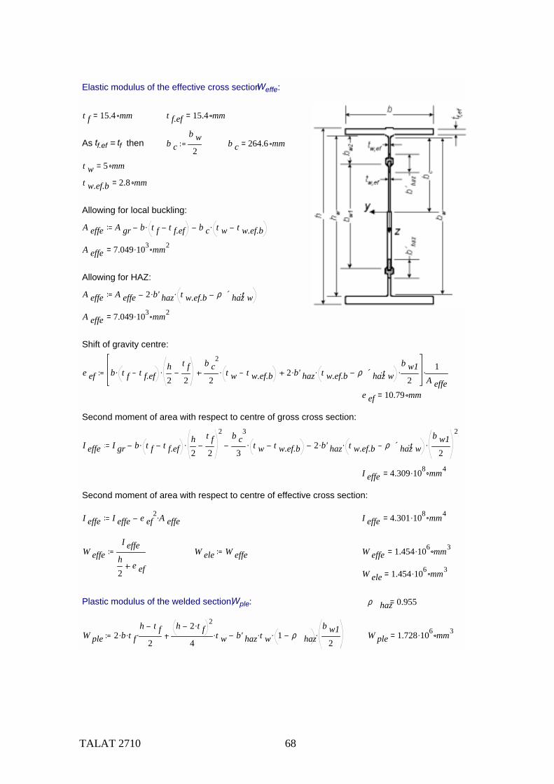
Elastic modulus of the effective cross section Weffe:
t f 15.4 mm= t f.ef 15.4 mm=
As tf.ef = tf then b cb w2
b c 264.6 mm=
t w 5 mm=
t w.ef.b 2.8 mm=
Allowing for local buckling:
A effe A gr b t f t f.ef. b c t w t w.ef.b.
A effe 7.049 103. mm2=
Allowing for HAZ:
A effe A effe 2 b' haz. t w.ef.b ρ ´ hazt w..
A effe 7.049 103. mm2=
Shift of gravity centre:
e ef b t f t f.ef. h2
t f2
.b c
2
2t w t w.ef.b. 2 b' haz. t w.ef.b ρ ´ hazt w..
b w12
. 1A effe
.
e ef 10.79 mm=
Second moment of area with respect to centre of gross cross section:
I effe I gr b t f t f.ef. h2
t f2
2
.b c
3
3t w t w.ef.b. 2 b' haz. t w.ef.b ρ ´ hazt w..
b w12
2
.
I effe 4.309 108. mm4=
Second moment of area with respect to centre of effective cross section:
I effe I effe e ef2 A effe. I effe 4.301 108. mm4=
W effeI effe
h2
e ef
W ele W effe W effe 1.454 106. mm3=
W ele 1.454 106. mm3=
Plastic modulus of the welded section, Wple: ρ haz 0.955=
W ple 2 b. t f.h t f
2.
h 2 t f. 2
4t w. b' haz t w. 1 ρ haz.
b w12
. W ple 1.728 106. mm3=

TALAT 2710 69
[1] Tab. 5.3 Shape factor α
- for welded, class 1 or 2 cross-sections:
α 1.2.wW pleW el
α 1.2.w 1.108=
- for welded, class 3 cross-sections:
[1] (5.16) α 3.wwW eleW el
β 3w β wβ 3w β 2w
W ple W eleW el
. α 3.ww 0.048=
[1] (5.16) α 3.wfW eleW el
β 3f β fβ 3f β 2f
W ple W eleW el
. α 3.wf 1.073=
β, β2, β3 are the slenderness parameter and the limiting values for the most critical element in the cross-section, so it is the smaller value of α3.ww and α3.wf
α 3.w if α 3.ww α 3.wf α 3.ww, α 3.wf, α 3.w 0.048=
- for welded, class 4 cross-sections: α 4.wW effeW el
α 4.w 0.933=
class 4=
α if class 2> if class 3> α 4.w, α 3.w,, α 1.2.w, α 0.933=
Design moment of resistance of the cross section Mc,Rd
[1] (5.14) M c.Rdf o α. W el.
γ M1M c.Rd 343.7 kNm=
6.6.6 Lateral-torsional buckling between purlins
[1] 5.9.4.3
Lateral stiffness constant I z2 b3. t f.
12
h t w3.
12I z 1.052 107. mm4=
[1] Figure J.2 Varping constant: I wh t f
2 I z.
4I w 8.089 1011. mm6=
Torsional constant: I t2 b. t f
3. h t w3.
3I t 4.133 105. mm4=
Length between purlins c p c p 1 103. mm=
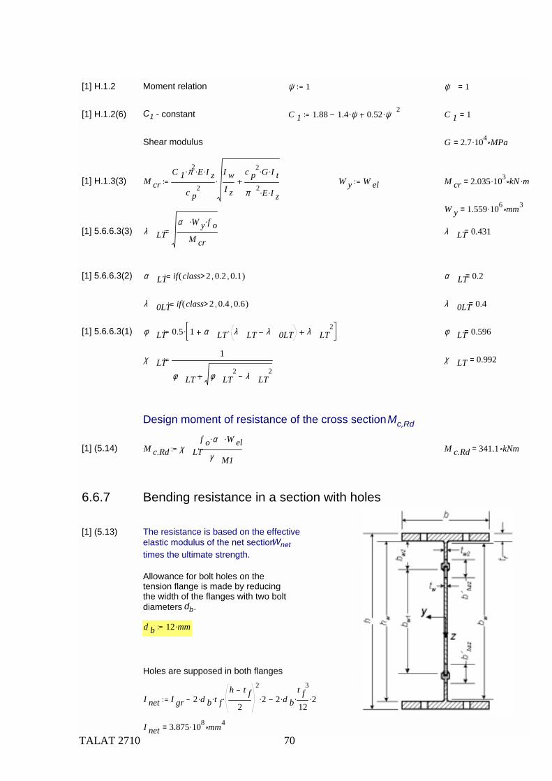
TALAT 2710 70
[1] H.1.2 Moment relation ψ 1 ψ 1=
[1] H.1.2(6) C1 - constant C 1 1.88 1.4 ψ. 0.52 ψ 2. C 1 1=
Shear modulus G 2.7 104. MPa=
[1] H.1.3(3) M crC 1 π2. E. I z.
c p2
I wI z
c p2 G. I t.
π 2 E. I z.. W y W el M cr 2.035 103. kN m.=
W y 1.559 106. mm3=
[1] 5.6.6.3(3) λ LTα W y. f o.
M crλ LT 0.431=
[1] 5.6.6.3(2) α LT if class 2> 0.2, 0.1,( ) α LT 0.2=
λ 0LT if class 2> 0.4, 0.6,( ) λ 0LT 0.4=
[1] 5.6.6.3(1) φ LT 0.5 1 α LT λ LT λ 0LT. λ LT2. φ LT 0.596=
χ LT1
φ LT φ LT2 λ LT
2χ LT 0.992=
Design moment of resistance of the cross section Mc,Rd
[1] (5.14) M c.Rd χ LTf o α. W el.
γ M1. M c.Rd 341.1 kNm=
6.6.7 Bending resistance in a section with holes
[1] (5.13) The resistance is based on the effectiveelastic modulus of the net section Wnet times the ultimate strength.
Allowance for bolt holes on thetension flange is made by reducingthe width of the flanges with two boltdiameters db.
d b 12 mm.
Holes are supposed in both flanges
I net I gr 2 d b. t f.h t f
2
2
. 2. 2 d b.t f
3
12. 2.
I net 3.875 108. mm4=
TALAT 2710 71
Allowance for HAZ ρ haz 0.955=
I net I net 2 t w. b' haz3. 1 ρ haz. 2 t w. b' haz. 1 ρ haz.
b w12
2
. I net 3.866 108. mm4=
W net2 I net.
h
f oγ M1
236 MPa= W net 1.356 106. mm3=
[1] (5.13) M a.Rdf u W net.
γ M2
f uγ M2
248 MPa= M a.Rd 336.4 kNm=
The bending resistance is the lesser of Ma.Rd and Mc.Rd
M Rd if M a.Rd M c.Rd< M a.Rd, M c.Rd, M Rd 336.4 kNm=
6.6.8 Shear force resistance
[1] 5.12.4 Design shear resistance Vw.Rd for the web: A rigid end post is assumed
[1] (5.93) λ w 0.35b wt w
.f oE
. b w 529 mm= λ w 2.258=
η 0.4 0.2f uf o
. η 0.638=
[1] Tab. 5.12 ρ v if λ w0.48η
> if λ w 0.9490.48λ w
,0.48λ w
,, η, ρ v 0.213=
ρ v if λ w 0.949>1.32
1.66 λ w, ρ v, ρ v 0.337=
h w h 2 t w. h w 560 mm=
[1] (5.95) V w.Rd ρ vt w. h w.f o
γ M1. V w.Rd 222.99 kN=
[1] 5.12.5(7) Shear resistance contribution Vf.Rd of the flanges.
M f.Rd b t f. h w t f.f o
γ M1.
M 1EdM f.Rd
0.436= M f.Rd 335 kNm=
a L a 1 104. mm=c 0.08
4.4 b. t f2. f o.
t w b2. f o.a. c 1.384 104. mm=
TALAT 2710 72
[1] (5.101) V f.Rd if M 1Ed M f.Rd<b t f
2. f o.
c γ M1.1
M 1EdM f.Rd
2
., 0, V f.Rd 0.5 kN=
V Rd V w.Rd V f.Rd V Rd 223.5 kN=
6.6.9 Concentrated transverse force[1] 5.12.8
[1] Figure 5.24 Length of stiff bearing s s 50 mm. h w 560 mm=
[1] (5.109) Parameter m1 b f b f of f o f ow f o m 1f of b f.
f ow t w. m 1 32=
[1] Figure 5.24 Buckling coefficient k F 6 2h wa
2
. k F 6.01=
[1] (5.110) Parameter m2 m 2 ifs s 4 t f. h w. f ow.
k F E. t w2.
0.2> 0.02h wt f
2
., 0, m 2 26.4=
[1] (5.111) Effective loaded length ly l y s s 2 t f. 1 m 1 m 2. l y 316.3 mm=
[1] (5.108) Design resistance FRd F Rd 0.57 t w2.
k F l y. f ow. E.
h w. 1
γ M1. F Rd 101.8 kN=
F Rd if F Rd t w l y.f owγ M1
.> t w l y.f ow
γ M1., F Rd, F Rd 101.8 kN=
Applied load F Ed q p.roof q snow c p. c p 1 m= F Ed 13.75 kN=
FEd << FRd OK!
6.6.10 DeflectionsTo calculate the fictive second moment of area I fic, the bending moment in the serviceability limistate is supposed to be half the maximum bending moment at the ultimate limit state.
[1] 4.2.4 σ gr0.5 M Ed.
I gr
h2
. I gr 4.444 108. mm4= σ gr 108 MPa=
Allowing for a reduced stress level, Ific may be used constant along the beam.
[1] (4.2) I fic I grσ grf o
I gr I effe. I fic 4.385 108. mm4=
I if class 4 I fic, I gr, class 4= I 4.385 108. mm4=
TALAT 2710 73
Approximate deflections (coefficients from FE calculations)
δ 1 0.75 q p.roof. L4.
384 E. I.. q p.roof 2.75 kN m 1.= δ 1 8.2 mm=
δ k.roof 0.755 q k.roof. L4.
384 E. I.. q k.roof 4.125 kN m 1.= δ k.roof 13.1 mm=
δ crane 0.75P crane L3.
48 E. I.. P crane 50 kN= δ crane 25.45 mm=
δ snow 0.655 q snow. L4.
384 E. I.. q snow 11 kN m 1.= δ snow 30.3 mm=
δ w.roof 0.755 q w.roof. L4.
384 E. I.. q w.roof 3.85 kN m 1.= δ w.roof 12.3 mm=
[5] 9.5.2 Frequent load combination no. 3, snow load dominant
[5] (9.16) δ 2 0 δ k.roof. 0.3 δ crane. 0.2 δ snow. 0 δ w.roof. δ 2 14 mm=
Pre-camber δ 0 0 mm.
[1] (4.1) δ max δ 1 δ 2 δ 0 δ max 21.9 mm=
The FEM calculation gives for the same load combination δ max 20.2 mm.
(1.1) δ limitL
250for beams carrying roof δ limit 40 mm=
6.6.11 Summary M Rd 336 kNm=
M Ed 336 kNm= M c.Rd 341 kNm= M 1Ed 146 kNm=M EdM Rd
0.999=
V Ed 172 kN= V Rd 223.5 kN= V EdV Rd
0.77=
δ limit 40 mm= δ max 20 mm= I fic 4.385 108. mm4=
Cross section h 570 mm= b 160 mm= t w 5 mm= t f 15.4 mm= A gr 7.624 103. mm2=
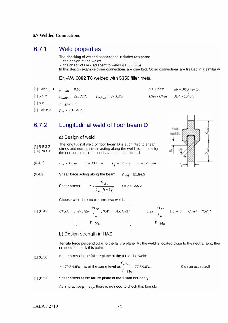
TALAT 2710 74
6.7 Welded Connections
6.7.1 Weld propertiesThe checking of welded connections includes two parts: - the design of the welds - the check of HAZ adjacent to welds ([1] 6.6.3.5)In this design example three connections are checked. Other connections are treated in a similar wa
EN-AW 6082 T6 welded with 5356 filler metal
[1] Tab 5.5.1 ρ haz 0.65 S.I. units: kN 1000 newton.
[1] 5.5.2 f a.haz 220 MPa. f v.haz 97 MPa. kNm kN m. MPa 106 Pa.
[1] 6.6.1 γ Mw 1.25
[1] Tab 6.8 f w 210 MPa.
6.7.2 Longitudinal weld of floor beam D
a) Design of weldThe longitudinal weld of floor beam D is submitted to shear stress and normal stress acting along the weld axis. In design the normal stress does not have to be considered.
[1] 6.6.3.3(10) NOTE
(6.4.1) t w 4 mm. h 300 mm. t f 12 mm. b 120 mm.
(6.4.2) Shear force acting along the beam V Ed 91.6 kN.
Shear stress τV Ed
t w h t f. τ 79.5 MPa=
Choose weld throat a 3 mm. , two welds
[1] (6.42) Check if a 0.85τ t w.
f wγ Mw
.> "OK!", "Not OK!", 0.85τ t w.
f wγ Mw
. 1.6 mm= Check "OK!"=
b) Design strength in HAZ
Tensile force perpendicular to the failure plane: As the weld is located close to the neutral axis, therno need to check this point.
Shear stress in the failure plane at the toe of the weld:[1] (6.50)
τ 79.5 MPa= is at the same level as f v.hazγ Mw
77.6 MPa= . Can be accepted!
[1] (6.51) Shear stress at the failure plane at the fusion boundary:
As in practice g 1 t w> , there is no need to check this formula
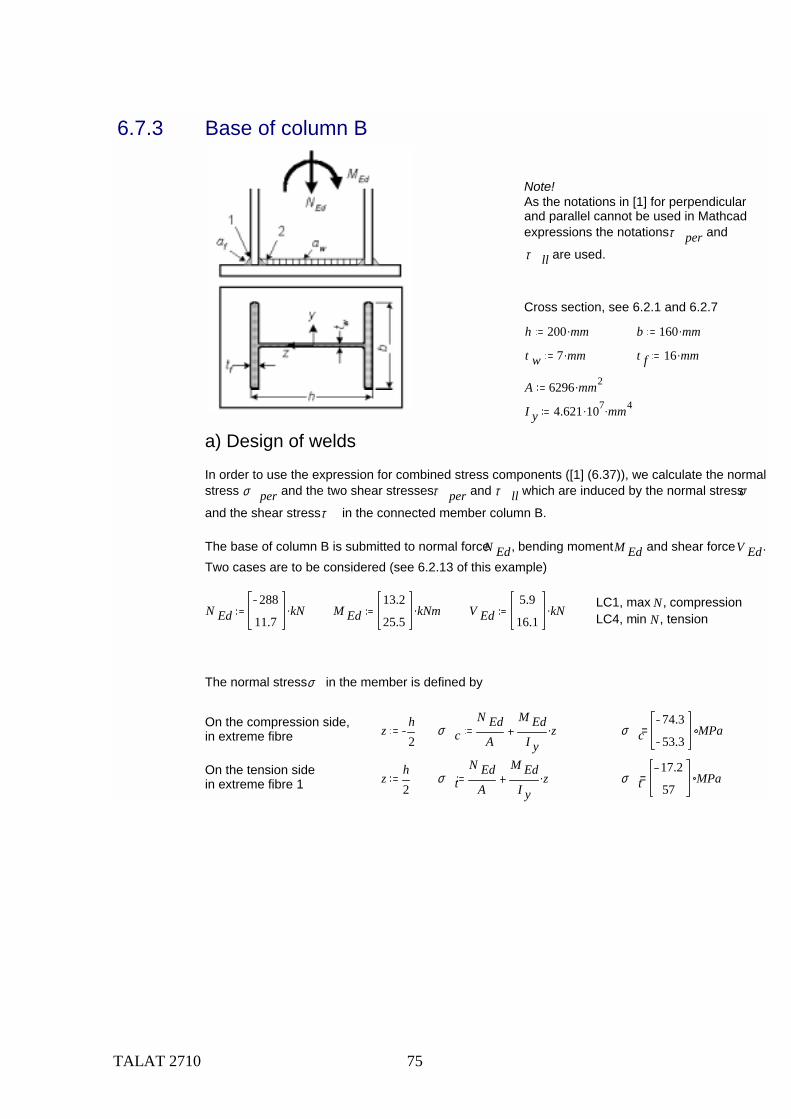
TALAT 2710 75
6.7.3 Base of column B
Note!As the notations in [1] for perpendicular and parallel cannot be used in Mathcad expressions the notations τ per and
τ ll are used.
Cross section, see 6.2.1 and 6.2.7
h 200 mm. b 160 mm.
t w 7 mm. t f 16 mm.
A 6296 mm2.
I y 4.621 107. mm4.
a) Design of welds
In order to use the expression for combined stress components ([1] (6.37)), we calculate the normal stress σ per and the two shear stresses τ per and τ ll which are induced by the normal stress σ
and the shear stress τ in the connected member column B.
The base of column B is submitted to normal force N Ed, bending moment M Ed and shear force V Ed. Two cases are to be considered (see 6.2.13 of this example)
LC1, max N, compressionLC4, min N, tensionN Ed
288
11.7kN. M Ed
13.2
25.5kNm. V Ed
5.9
16.1kN.
The normal stress σ in the member is defined by
On the compression side,in extreme fibre z
h2
σ cN Ed
A
M EdI y
z. σ c74.3
53.3MPa=
On the tension side in extreme fibre 1 z
h2
σ tN Ed
A
M EdI y
z. σ t17.2
57MPa=
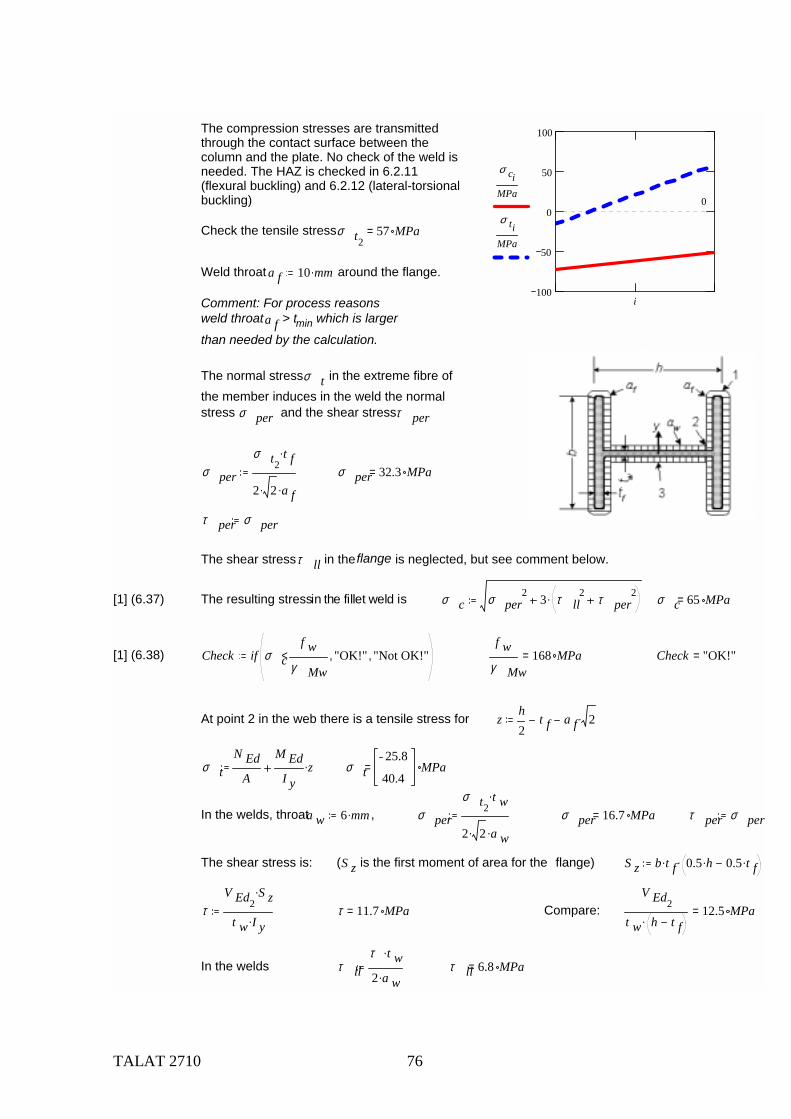
TALAT 2710 76
100
50
0
50
100
0
σ ciMPa
σ tiMPa
i
The compression stresses are transmittedthrough the contact surface between the column and the plate. No check of the weld is needed. The HAZ is checked in 6.2.11 (flexural buckling) and 6.2.12 (lateral-torsional buckling)
Check the tensile stress σ t257 MPa=
Weld throat a f 10 mm. around the flange.
Comment: For process reasons weld throat a f > tmin which is larger than needed by the calculation.
The normal stress σ t in the extreme fibre of the member induces in the weld the normal stress σ per and the shear stress τ per
σ per
σ t2t f.
2 2. a f.σ per 32.3 MPa=
τ per σ per
The shear stress τ ll in the flange is neglected, but see comment below.
[1] (6.37) The resulting stress in the fillet weld is σ c σ per2 3 τ ll
2 τ per2. σ c 65 MPa=
[1] (6.38) Check if σ cf w
γ Mw< "OK!", "Not OK!",
f wγ Mw
168 MPa= Check "OK!"=
At point 2 in the web there is a tensile stress for zh2
t f a f 2.
σ tN Ed
A
M EdI y
z. σ t25.8
40.4MPa=
In the welds, throat a w 6 mm. , σ per
σ t2t w.
2 2. a w.σ per 16.7 MPa= τ per σ per
The shear stress is: (S z is the first moment of area for the flange) S z b t f. 0.5 h. 0.5 t f..
τV Ed2
S z.
t w I y. τ 11.7 MPa= Compare: V Ed2
t w h t f. 12.5 MPa=
In the welds τ llτ t w.
2 a w. τ ll 6.8 MPa=

TALAT 2710 77
[1] (6.37) The resulting stress in the fillet weld is σ c σ per2 3 τ ll
2 τ per2. σ c 35 MPa=
[1] (6.38) Check if σ cf w
γ Mw< "OK!", "Not OK!",
f wγ Mw
168 MPa= Check "OK!"=
Comment: The shear stress in the flange can be calculated with the expression:
τV Ed
2 t f. h t f. 1t w h t f.
6 t f. b..
τ0.925
2.523MPa=
b) Check of HAZ
[1] (6.46) The HAZ is checked in 6.2.11 (flexural buckling) and 6.2.12 (lateral-torsional buckling). As g 1 a> , no check at the fusion boundary is needed. [1] (6.47)
6.7.4 Connection between floor beam D and column B
The diagonal stiffeners (on both sides) are welded first with unsymmetric fillet welds. Then the horizontal stiffeners are welded with butt weld to the flanges close to the diagonals and with fillet weto the web.
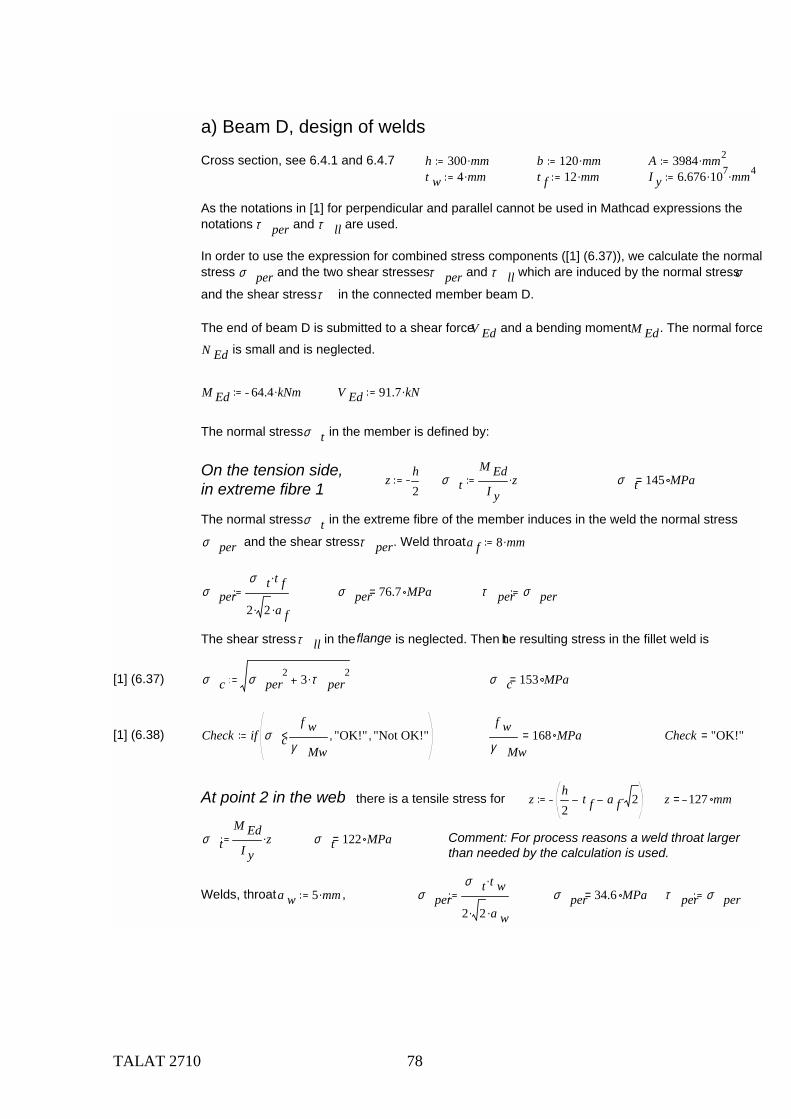
TALAT 2710 78
a) Beam D, design of welds
Cross section, see 6.4.1 and 6.4.7 h 300 mm. b 120 mm. A 3984 mm2.t w 4 mm. t f 12 mm. I y 6.676 107. mm4.
As the notations in [1] for perpendicular and parallel cannot be used in Mathcad expressions the notations τ per and τ ll are used.
In order to use the expression for combined stress components ([1] (6.37)), we calculate the normalstress σ per and the two shear stresses τ per and τ ll which are induced by the normal stress σ
and the shear stress τ in the connected member beam D.
The end of beam D is submitted to a shear force V Ed and a bending moment M Ed. The normal force
N Ed is small and is neglected.
M Ed 64.4 kNm. V Ed 91.7 kN.
The normal stress σ t in the member is defined by:
On the tension side,in extreme fibre 1
zh2
σ tM Ed
I yz. σ t 145 MPa=
The normal stress σ t in the extreme fibre of the member induces in the weld the normal stress
σ per and the shear stress τ per. Weld throat a f 8 mm.
σ perσ t t f.
2 2. a f.σ per 76.7 MPa= τ per σ per
The shear stress τ ll in the flange is neglected. Then the resulting stress in the fillet weld is
[1] (6.37) σ c σ per2 3 τ per
2. σ c 153 MPa=
[1] (6.38) Check if σ cf w
γ Mw< "OK!", "Not OK!",
f wγ Mw
168 MPa= Check "OK!"=
At point 2 in the web there is a tensile stress for zh2
t f a f 2. z 127 mm=
σ tM Ed
I yz. σ t 122 MPa= Comment: For process reasons a weld throat larger
than needed by the calculation is used.
Welds, throat a w 5 mm. , σ perσ t t w.
2 2. a w.σ per 34.6 MPa= τ per σ per
TALAT 2710 79
The shear stress is: (S z is the first moment of area for the flange) S z b t f. 0.5 h. 0.5 t f..
τV Ed S z.
t w I y. τ 71.2 MPa= Compare: V Ed
t w h t f. 79.6 MPa=
In the welds τ llτ t w.
2 a w. τ ll 28.5 MPa=
[1] (6.37) The resulting stress in the fillet weld is σ c σ per2 3 τ ll
2 τ per2. σ c 85 MPa=
[1] (6.38) Check if σ cf w
γ Mw< "OK!", "Not OK!",
f wγ Mw
168 MPa= Check "OK!"=
In the middle of the web, point 3
σ t 0 MPa. τV Ed
t w h t f. τ llτ t w.
2 a w. τ ll 31.8 MPa=
[1] (6.37) The resulting stress in the fillet weld is σ c 3 τ ll. σ c 55 MPa=
[1] (6.38) Check if σ cf w
γ Mw< "OK!", "Not OK!",
f wγ Mw
168 MPa= Check "OK!"=
b) Beam D, design strength HAZ
Verify in the HAZ
[1] (6.54) - at the toe of the weld: σ 2 3 τ 2.f a.hazγ Mw
[1] (6.55) - at the fusion boundary: σ 2 3 τ 2.g 1 f a.haz.
t γ Mw.
As in practice g 1 t> , there is no need to check the formula at the fusion boundary.
In the flange: σ σ 1 145 MPa. τ 0 MPa. σ c σ 12 3 τ 2. σ c 145 MPa=
[1] (6.54) Check if σ cf a.hazγ Mw
< "OK!", "Not OK!",f a.hazγ Mw
176 MPa= Check "OK!"=
In the web: σ 122 MPa. τ 71 MPa. σ c σ 2 3 τ 2. σ c 173 MPa=
[1] (6.54) Check if σ cf a.hazγ Mw
< "OK!", "Not OK!",f a.hazγ Mw
176 MPa= Check "OK!"=
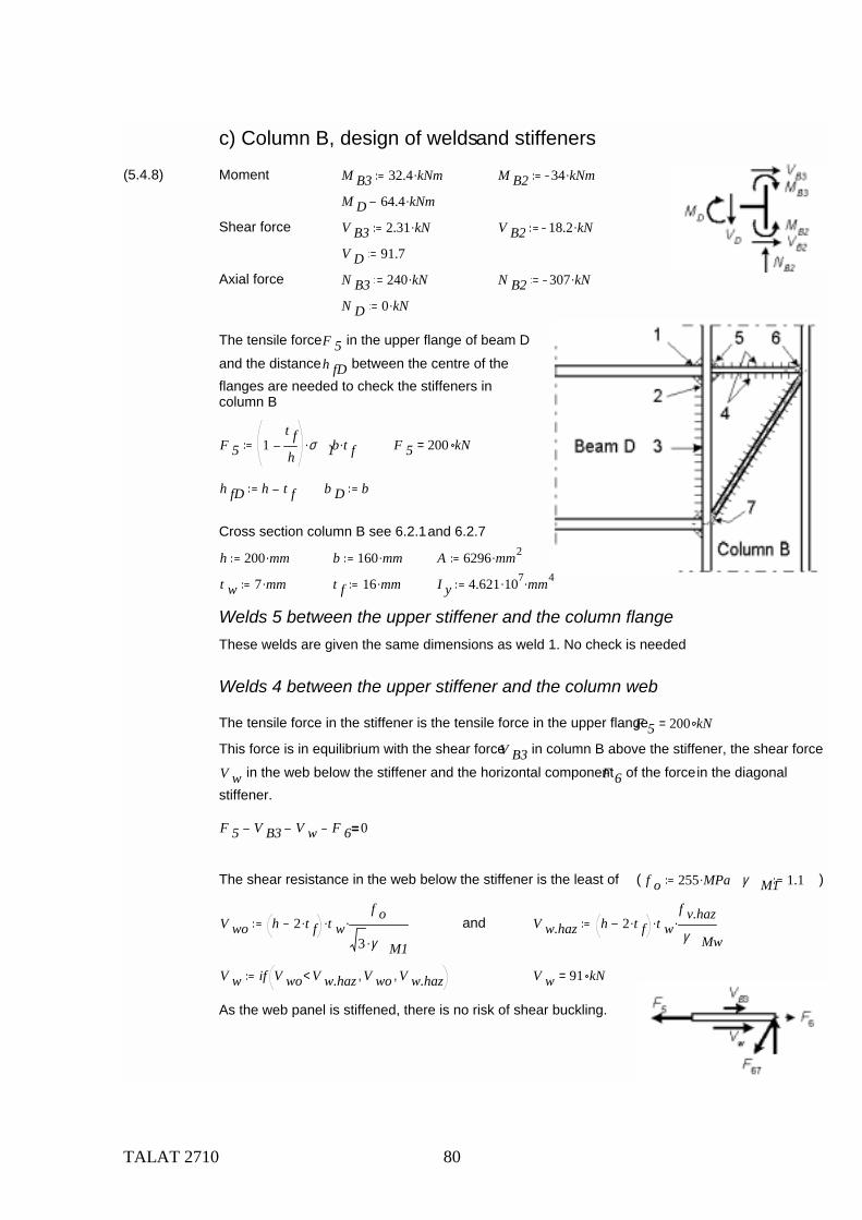
TALAT 2710 80
c) Column B, design of welds and stiffeners
(5.4.8) Moment M B3 32.4 kNm. M B2 34 kNm.
M D 64.4 kNm.
Shear force V B3 2.31 kN. V B2 18.2 kN.
V D 91.7
Axial force N B3 240 kN. N B2 307 kN.
N D 0 kN.
The tensile force F 5 in the upper flange of beam D and the distance h fD between the centre of the flanges are needed to check the stiffeners in column B
F 5 1t fh
σ 1. b. t f. F 5 200 kN=
h fD h t f b D b
Cross section column B see 6.2.1 and 6.2.7
h 200 mm. b 160 mm. A 6296 mm2.
t w 7 mm. t f 16 mm. I y 4.621 107. mm4.
Welds 5 between the upper stiffener and the column flangeThese welds are given the same dimensions as weld 1. No check is needed
Welds 4 between the upper stiffener and the column web
The tensile force in the stiffener is the tensile force in the upper flange F 5 200 kN=
This force is in equilibrium with the shear force V B3 in column B above the stiffener, the shear force
V w in the web below the stiffener and the horizontal component F 6 of the force in the diagonal stiffener.
F 5 V B3 V w F 6 0
The shear resistance in the web below the stiffener is the least of ( f o 255 MPa. γ M1 1.1 )
V wo h 2 t f. t w.f o
3 γ M1.. and V w.haz h 2 t f. t w.
f v.hazγ Mw
.
V w if V wo V w.haz< V wo, V w.haz, V w 91 kN=
As the web panel is stiffened, there is no risk of shear buckling.
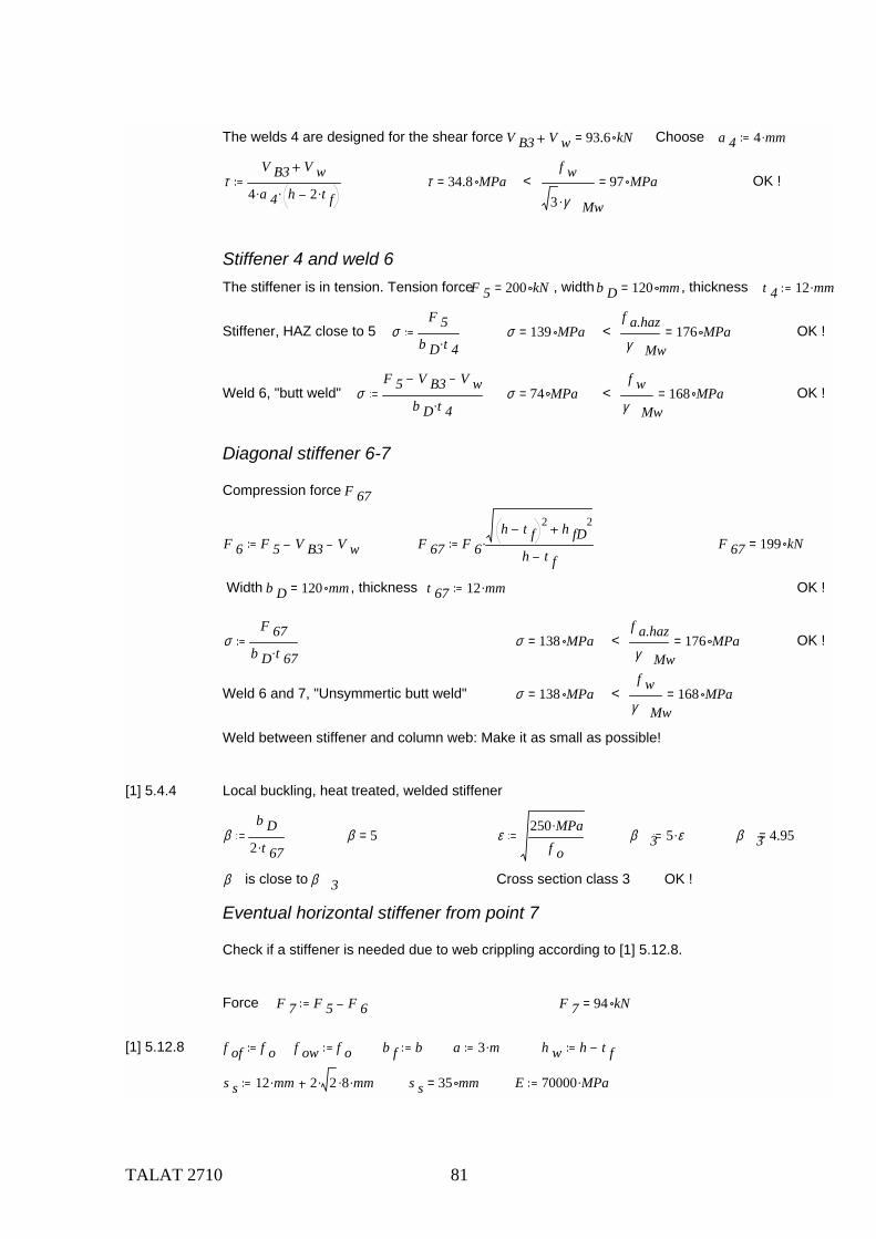
TALAT 2710 81
The welds 4 are designed for the shear force V B3 V w 93.6 kN= Choose a 4 4 mm.
τV B3 V w
4 a 4. h 2 t f.. τ 34.8 MPa= < f w
3 γ Mw.97 MPa= OK !
Stiffener 4 and weld 6The stiffener is in tension. Tension forceF 5 200 kN= , width b D 120 mm= , thickness t 4 12 mm.
Stiffener, HAZ close to 5 σF 5
b D t 4. σ 139 MPa= < f a.hazγ Mw
176 MPa= OK !
Weld 6, "butt weld" σF 5 V B3 V w
b D t 4. σ 74 MPa= < f w
γ Mw168 MPa= OK !
Diagonal stiffener 6-7
Compression force F 67
F 6 F 5 V B3 V w F 67 F 6h t f
2 h fD2
h t f. F 67 199 kN=
Width b D 120 mm= , thickness t 67 12 mm. OK !
σF 67
b D t 67. σ 138 MPa= < f a.hazγ Mw
176 MPa= OK !
Weld 6 and 7, "Unsymmertic butt weld" σ 138 MPa= < f w
γ Mw168 MPa=
Weld between stiffener and column web: Make it as small as possible!
[1] 5.4.4 Local buckling, heat treated, welded stiffener
βb D
2 t 67. β 5= ε250 MPa.
f oβ 3 5 ε. β 3 4.95=
β is close to β 3 Cross section class 3 OK !
Eventual horizontal stiffener from point 7
Check if a stiffener is needed due to web crippling according to [1] 5.12.8.
Force F 7 F 5 F 6 F 7 94 kN=
[1] 5.12.8 f of f o f ow f o b f b a 3 m. h w h t f
s s 12 mm. 2 2. 8. mm. s s 35 mm= E 70000 MPa.
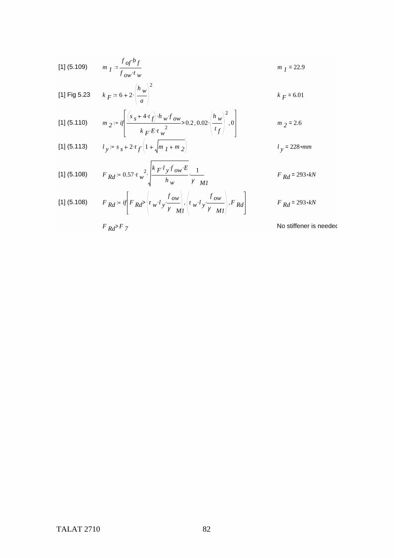
TALAT 2710 82
[1] (5.109) m 1f of b f.
f ow t w. m 1 22.9=
[1] Fig 5.23 k F 6 2h wa
2
. k F 6.01=
[1] (5.110) m 2 ifs s 4 t f. h w. f ow.
k F E. t w2.
0.2> 0.02h wt f
2
., 0, m 2 2.6=
[1] (5.113) l y s s 2 t f. 1 m 1 m 2. l y 228 mm=
[1] (5.108) F Rd 0.57 t w2.
k F l y. f ow. E.
h w. 1
γ M1. F Rd 293 kN=
[1] (5.108) F Rd if F Rd t w l y.f owγ M1
.> t w l y.f ow
γ M1., F Rd, F Rd 293 kN=
F Rd F 7> No stiffener is needed
Recommended


![Staphylococcus cohnii subsp. cohnii...TAS [20] Phylum . Firmicutes. TAS [21-23] Class . Bacilli. TAS [24,25] Current classification Order . Bacillales. TAS [26,27] Family . Staphylococcaceae](https://img.dokumen.tips/doc/110x75/60a52ad9c3f72c10995ebd7d/staphylococcus-cohnii-subsp-cohnii-tas-20-phylum-firmicutes-tas-21-23.jpg)