Prediction of Axial Compressor Blade Vibration
by Modelling Fluid-Structure Interaction
Faculty of Engineering at Stellenbosch University
Department of Mechanical and
Mechatronic Engineering
by J. D Brandsen
Supervisors:
Dr S. J. van der Spuy
Prof G. Venter
1/19
Overview
• Background
• Goal of Project
• FSI Modelling Approaches
• Experimental Work
• Numerical Modelling
• Results
• Conclusions
2/19
Background
Flutter in Turbomachinery
Background
Goal of Project
FSI Modelling
Approaches
Experimental
Work
Numerical
Modelling
Results
Conclusions
• Flutter is the vibration of a mechanical system:
At or near natural frequencies of system.
Caused by instability. Does not require disturbance.
Aerodynamic forces feed energy into system. Amplitude
increases with time.
• Cause of high cycle fatigue failure in turbomachinery.
• Project FUTURE initiated to improve methods used to model
and design for flutter.
• Project FUTURE is coordinated by Kungliga Teknista
Högskolan in Sweden.
• Also has 25 other partners, including Stellenbosch University
and the Council for Scientific and Industrial Research (CSIR).
3/19
Background (continued)
Vibration Excitation System
Background
Goal of Project
FSI Modelling
Approaches
Experimental
Work
Numerical
Modelling
Results
Conclusions
• As part of Project FUTURE, the CSIR have developed a
vibration excitation system:
Designed to excite the first rotor blade row of an axial
flow compressor.
Designed to make the blade row vibrate at the desired
frequency and in the desired mode shape.
Injects air into compressor flow path thereby causing
velocity perturbations.
• Stellenbosch University responsible for demonstrating
capabilities of vibration excitation system.
• Vibration excitation system was therefore fitted to the
Rofanco compressor test bench.
4/19
Background (continued)
Vibration Excitation System
Background
Goal of Project
FSI Modelling
Approaches
Experimental
Work
Numerical
Modelling
Results
Conclusions
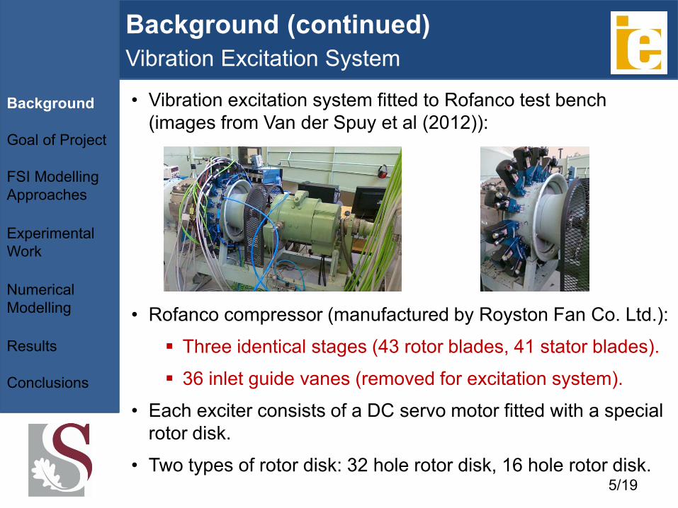
• Vibration excitation system fitted to Rofanco test bench
(images from Van der Spuy et al (2012)):
• Rofanco compressor (manufactured by Royston Fan Co. Ltd.):
Three identical stages (43 rotor blades, 41 stator blades).
36 inlet guide vanes (removed for excitation system).
• Each exciter consists of a DC servo motor fitted with a special
rotor disk.
• Two types of rotor disk: 32 hole rotor disk, 16 hole rotor disk. 5/19
Background (continued)
Blade Row Vibration Modes
Background
Goal of Project
FSI Modelling
Approaches
Experimental
Work
Numerical
Modelling
Results
Conclusions
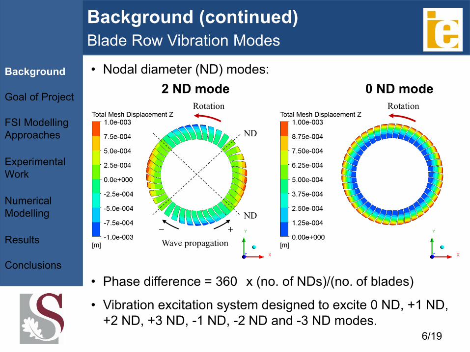
• Phase difference = 360
x (no. of NDs)/(no. of blades)
• Vibration excitation system designed to excite 0 ND, +1 ND,
+2 ND, +3 ND, -1 ND, -2 ND and -3 ND modes.
• Nodal diameter (ND) modes:
+ −
Rotation
Wave propagation
ND
ND
Rotation
2 ND mode 0 ND mode
6/19
Goal of Project
Background
Goal of Project
FSI Modelling
Approaches
Experimental
Work
Numerical
Modelling
Results
Conclusions
• Goal of thesis project:
Construct a FSI model of the vibration excitation system.
• Purpose of FSI model was two-fold:
Numerical tool for carrying out experiments digitally.
Will complement the existing experimental data.
• Restrictions placed on FSI model due to time constraints:
Single setting simulated: excitation frequency of 660 Hz
and a supply pressure of 2.5 bar.
Needs to only be able to simulate the 0 ND mode and
the +2 ND mode of the system.
Must be able to accurately recreate component of blade
motion occuring at excitation frequency (660 Hz).
7/19
FSI Modelling Approaches
Background
Goal of Project
FSI Modelling
Approaches
Experimental
Work
Numerical
Modelling
Results
Conclusions
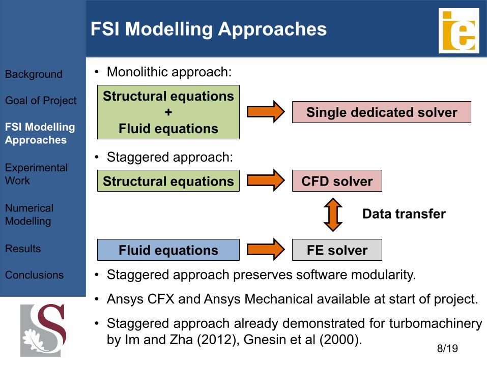
• Monolithic approach:
• Staggered approach:
Structural equations
+
Fluid equations
Structural equations
Fluid equations
Single dedicated solver
CFD solver
FE solver
Data transfer
• Staggered approach preserves software modularity.
• Ansys CFX and Ansys Mechanical available at start of project.
• Staggered approach already demonstrated for turbomachinery
by Im and Zha (2012), Gnesin et al (2000). 8/19
Experimental Work
Background
Goal of Project
FSI Modelling
Approaches
Experimental
Work
Numerical
Modelling
Results
Conclusions
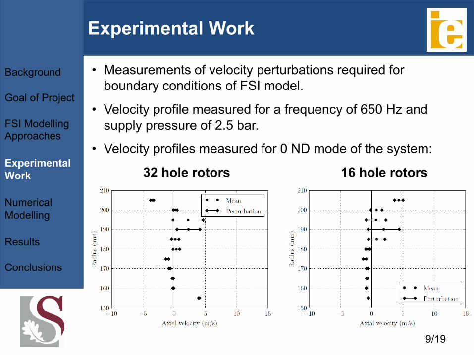
• Measurements of velocity perturbations required for
boundary conditions of FSI model.
• Velocity profile measured for a frequency of 650 Hz and
supply pressure of 2.5 bar.
• Velocity profiles measured for 0 ND mode of the system:
32 hole rotors 16 hole rotors
9/19
Numerical Modelling
FE Model of First Rotor Blade Row
Background
Goal of Project
FSI Modelling
Approaches
Experimental
Work
Numerical
Modelling
Results
Conclusions
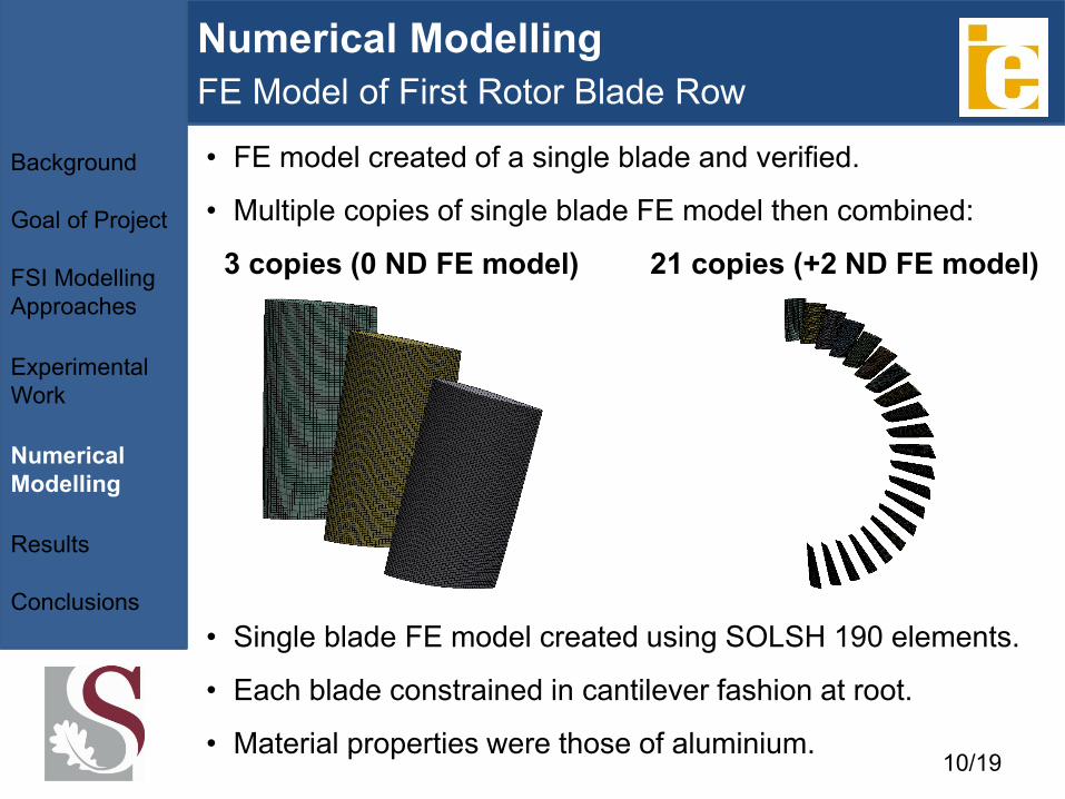
• FE model created of a single blade and verified.
• Multiple copies of single blade FE model then combined:
• Single blade FE model created using SOLSH 190 elements.
• Each blade constrained in cantilever fashion at root.
• Material properties were those of aluminium.
3 copies (0 ND FE model) 21 copies (+2 ND FE model)
10/19
Numerical Modelling (continued)
CFD Model of Vibration Excitation System
Background
Goal of Project
FSI Modelling
Approaches
Experimental
Work
Numerical
Modelling
Results
Conclusions
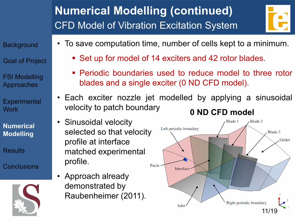
• To save computation time, number of cells kept to a minimum.
Set up for model of 14 exciters and 42 rotor blades.
Periodic boundaries used to reduce model to three rotor
blades and a single exciter (0 ND CFD model).
• Each exciter nozzle jet modelled by applying a sinusoidal
velocity to patch boundary
• Sinusoidal velocity
selected so that velocity
profile at interface
matched experimental
profile.
0 ND CFD model
• Approach already
demonstrated by
Raubenheimer (2011).
11/19
Numerical Modelling (continued)
CFD Model of Vibration Excitation System
Background
Goal of Project
FSI Modelling
Approaches
Experimental
Work
Numerical
Modelling
Results
Conclusions
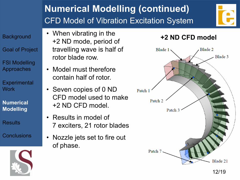
• When vibrating in the
+2 ND mode, period of
travelling wave is half of
rotor blade row.
• Model must therefore
contain half of rotor.
• Seven copies of 0 ND
CFD model used to make
+2 ND CFD model.
• Results in model of
7 exciters, 21 rotor blades
• Nozzle jets set to fire out
of phase.
+2 ND CFD model
12/19
Results
FFTs of blade deformation
Background
Goal of Project
FSI Modelling
Approaches
Experimental
Work
Numerical
Modelling
Results
Conclusions
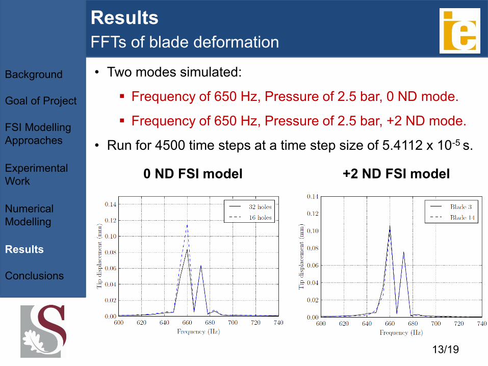
• Two modes simulated:
Frequency of 650 Hz, Pressure of 2.5 bar, 0 ND mode.
Frequency of 650 Hz, Pressure of 2.5 bar, +2 ND mode.
• Run for 4500 time steps at a time step size of 5.4112 x 10⁻⁵ s.
+2 ND FSI model 0 ND FSI model
13/19
Results (continued)
FFTs of blade deformation
Background
Goal of Project
FSI Modelling
Approaches
Experimental
Work
Numerical
Modelling
Results
Conclusions
• Data of Van der Spuy et al (2012) shows amplitude of 660 Hz
component of tip displacement perpendicular to root should
be:
0.089 mm for 0 ND mode for the 32 hole rotors.
0.105 mm for +2 ND mode for the 32 hole rotors.
• In both cases, amplitudes predicted by FSI models all within
6% of experimental data.
• Data of Van der Spuy et al (2012) shows amplitude of 660 Hz
component of bending strain, 6.1 mm from root, should be:
0.093 mm/m for 0 ND mode for the 32 hole rotors.
0.109 mm/m for +2 ND mode for the 32 hole rotors.
• As with tip displacement, amplitudes predicted by FSI
models all within between 10% and 20 % of experimental
data for both cases.
14/19
Results (continued)
Blade formation for 0 ND mode
Background
Goal of Project
FSI Modelling
Approaches
Experimental
Work
Numerical
Modelling
Results
Conclusions
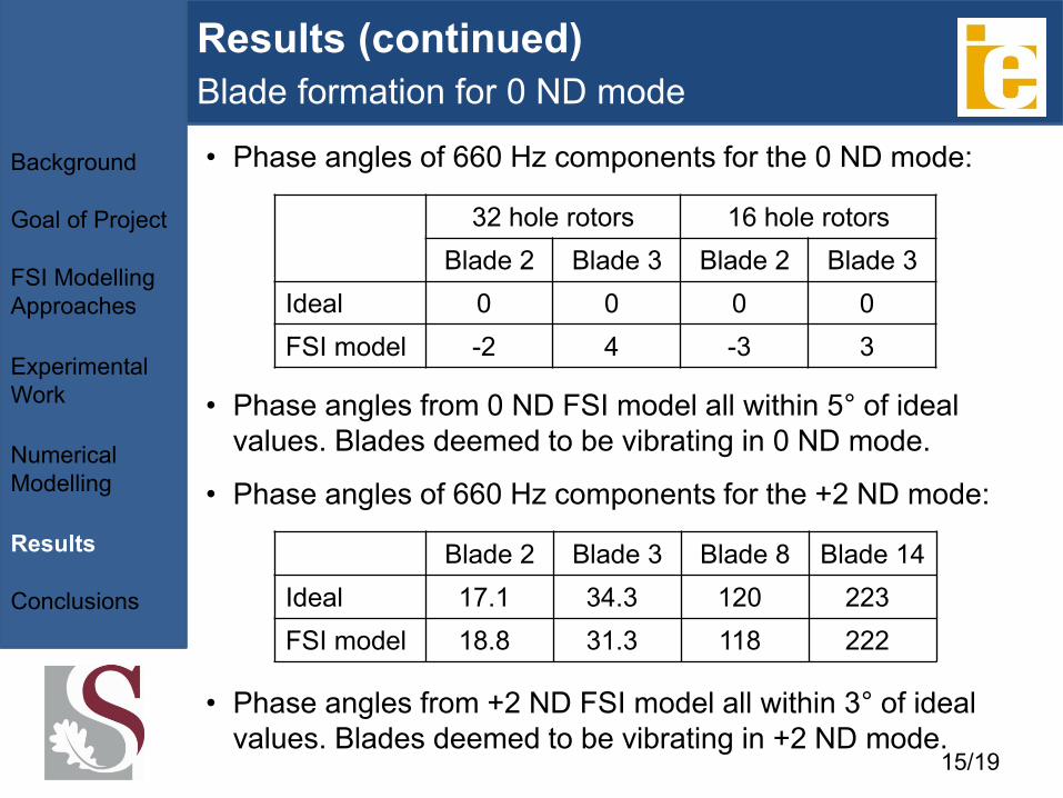
• Phase angles of 660 Hz components for the 0 ND mode:
Blade 2 Blade 3 Blade 8 Blade 14
Ideal 17.1
34.3
120
223
FSI model 18.8
31.3
118
222
32 hole rotors 16 hole rotors
Blade 2 Blade 3 Blade 2 Blade 3
Ideal 0
0
0
0
FSI model -2
4
-3
3
• Phase angles from 0 ND FSI model all within 5° of ideal
values. Blades deemed to be vibrating in 0 ND mode.
• Phase angles of 660 Hz components for the +2 ND mode:
• Phase angles from +2 ND FSI model all within 3° of ideal
values. Blades deemed to be vibrating in +2 ND mode. 15/19

Results (continued)
Visualisation of Blade Deformation
Background
Goal of Project
FSI Modelling
Approaches
Experimental
Work
Numerical
Modelling
Results
Conclusions
• Simulation of scenario where vibration excitation system is
set to 660 Hz, 2.5 bar and the 0 ND mode:
16/19
• Phase angles showed that the 660 Hz components of
motions of the blades are all in phase.
• However, visualisation shows that overall motions of the
blades are not in phase.
Conclusions
Background
Goal of Project
FSI Modelling
Approaches
Experimental
Work
Numerical
Modelling
Results
Conclusions
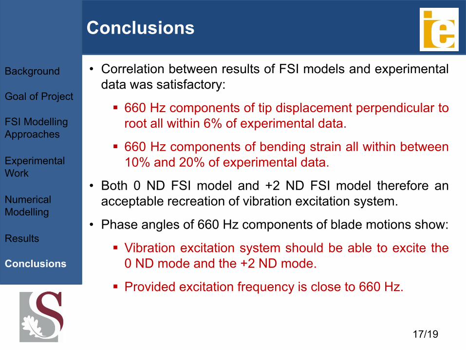
• Correlation between results of FSI models and experimental
data was satisfactory:
660 Hz components of tip displacement perpendicular to
root all within 6% of experimental data.
660 Hz components of bending strain all within between
10% and 20% of experimental data.
• Both 0 ND FSI model and +2 ND FSI model therefore an
acceptable recreation of vibration excitation system.
• Phase angles of 660 Hz components of blade motions show:
Vibration excitation system should be able to excite the
0 ND mode and the +2 ND mode.
Provided excitation frequency is close to 660 Hz.
17/19
Acknowledgements
• The financial assistance of the National Research Foundation (NRF)
towards this research is hereby acknowledged. Opinions expressed
and conclusions arrived at, are those of the author and are not
necessarily to be attributed to the NRF.
• Thank you to Project BALLAST for the financial assistance provided
for this thesis project.
18/19

Thank you
19/19
Recommended