POWERFULL
Visa S.p.A. Via I° Maggio, 55 – 31043 Fontanelle (TV)
Pagina 1 112000000001-001-01 – 0303/2009Printed in Italy. – All rights reserved.
POWERFULL GENERATING SETS
MAINTENANCE AND USER MANUAL
POWERFULL
Visa S.p.A. Via I° Maggio, 55 – 31043 Fontanelle (TV)
Pagina 2 112000000001-001-01 – 0303/2009Printed in Italy. – All rights reserved.
1. Introduction to the manual...................................................................................................... - 4 - 2. General description: parts of the unit and relevant terminology............................................. - 5 -
2.1. General constructive characteristics ..............................................................................................- 5 - 2.2. Engine (part. 1 fig. 1)......................................................................................................................- 6 - 2.3. Alternator (part. 2 fig. 1) .................................................................................................................- 6 - 2.4. Baseframe / fuel tank (part. 5 fig. 1)...............................................................................................- 6 - 2.5. Control panel (part. 3 fig. 1) ...........................................................................................................- 6 -
2.5.1. Manual control panel .................................................................................................................................- 7 - 2.5.2. Automatic panel with remote start .............................................................................................................- 7 - 2.5.3. Automatic panel for Mains failure (AMF) ...................................................................................................- 7 - 2.5.4. Optional functions......................................................................................................................................- 8 - 2.5.5. Changeover gear ATS-C and ATS-M........................................................................................................- 8 - 2.5.6. Automatic synchronisation panel isolated from the Mains.........................................................................- 8 - 2.5.7. Automatic synchronisation panel paralleling with the Mains......................................................................- 9 - 2.5.8. Special panels ...........................................................................................................................................- 9 - 2.5.9. Units without electrical equipment or control panel: safety norms. ............................................................- 9 -
2.6. Canopy (part. 10 fig. 1)...................................................................................................................- 9 - 2.7. Mufflers.........................................................................................................................................- 10 -
2.7.1. Exhaust mufflers (part. 14 fig. 1) .............................................................................................................- 10 - 2.7.2. Sound attenuators (part. 12-13 fig. 1)......................................................................................................- 10 -
2.8. Transport Trailer...........................................................................................................................- 10 - 3. Danger zones and safety gear ............................................................................................. - 11 -
3.1. Danger zones ...............................................................................................................................- 11 - 4. Moving the generating set.................................................................................................... - 15 -
4.1. General precautions for moving the unit ......................................................................................- 15 - 4.2. Moving method.............................................................................................................................- 15 -
4.2.1. Moving the generating set via forklift .......................................................................................................- 15 - 4.2.2. Moving the generating set via cables or chains.......................................................................................- 15 - 4.2.3. Moving the generating set via transport trailer.........................................................................................- 16 - 4.2.4. Moving the unit via motor vehicle ............................................................................................................- 16 -
5. Generating set User conditions............................................................................................ - 17 - 5.1. Generating set use .......................................................................................................................- 17 - 5.2. Generating set uses NOT permitted ............................................................................................- 17 - 5.3. Personnel in charge of handling the gensets...............................................................................- 17 - 5.4. Environmental conditions .............................................................................................................- 17 -
5.4.1. External influences on engine performance ............................................................................................- 17 - 5.4.2. External influences on alternator performance ........................................................................................- 18 -
5.5. Generating set power values .......................................................................................................- 18 - 6. Load conditions .................................................................................................................... - 19 -
6.1. User system .................................................................................................................................- 19 - 6.1.1. Non-linear loads ......................................................................................................................................- 19 - 6.1.2. Resistive loads (bulbs, heaters, resistances, etc.)...................................................................................- 19 - 6.1.3. Capacitive loads (condensers, discharge lamps, X-ray equipment, etc.) ................................................- 19 - 6.1.4. Inductive load (electric engines in general, electric fans, motor pumps, winches, etc.)...........................- 19 -
6.2. Load application ...........................................................................................................................- 20 - 6.3. Connections to alternator .............................................................................................................- 20 -
6.3.1. Star connection (sample of standard supply) ..........................................................................................- 20 - 6.3.2. Cyclical phase direction...........................................................................................................................- 21 -
7. Installation instructions......................................................................................................... - 21 - 7.1. General installation principles ......................................................................................................- 21 - 7.2. Outdoor installation ......................................................................................................................- 21 -
7.2.1. Environmental conditions ........................................................................................................................- 21 - 7.2.2. Output of fumes in open air conditions ....................................................................................................- 22 - 7.2.3. Safe distance...........................................................................................................................................- 22 - 7.2.4. Installing ..................................................................................................................................................- 22 - 7.2.5. Permanent outdoor installation................................................................................................................- 22 - 7.2.6. Temporary outdoor installation ................................................................................................................- 22 -
7.3. Indoor installation .........................................................................................................................- 23 - 7.3.1. Room size ...............................................................................................................................................- 23 - 7.3.2. Surface area............................................................................................................................................- 23 - 7.3.3. Room openings and ventilation ...............................................................................................................- 23 -
POWERFULL
Visa S.p.A. Via I° Maggio, 55 – 31043 Fontanelle (TV)
Pagina 3 112000000001-001-01 – 0303/2009Printed in Italy. – All rights reserved.
7.3.4. Exhaust conduit.......................................................................................................................................- 24 - 7.3.5. Engine oil breather pipe ..........................................................................................................................- 25 - 7.3.6. Installation of automatic fuel refilling system ...........................................................................................- 25 -
8. Electrical connections .......................................................................................................... - 27 - 8.1. Instructions for electrical connections ..........................................................................................- 27 - 8.2. Grounding.....................................................................................................................................- 27 -
8.2.1. Generating set with earth fault relay device.............................................................................................- 27 - 8.2.2. Generating set WITHOUT earth fault relay device ..................................................................................- 27 -
8.3. Synchronising between genset and Mains or between gensets..................................................- 27 - 9. Start-up instructions ............................................................................................................. - 28 -
9.1. General start-up principles ...........................................................................................................- 28 - 9.2. Necessary checks and operations to be carried out before start-up ...........................................- 28 - 9.3. Start-up in MANUAL mode...........................................................................................................- 29 - 9.4. Selecting MANUAL mode ............................................................................................................- 29 - 9.5. Start-up.........................................................................................................................................- 29 -
10. Instructions for disabling the generating set......................................................................... - 30 - 10.1. Normal stop ..................................................................................................................................- 30 - 10.2. Emergency stop ...........................................................................................................................- 30 - 10.3. Disabling the unit for maintenance and inspection operations or of the Mains............................- 30 -
11. Generating set maintenance and inspection........................................................................ - 31 - 11.1. General instructions for maintenance and inspection ..................................................................- 31 - 11.2. Ordinary maintenance..................................................................................................................- 32 - 11.3. Problems signalled by the “Guard Evolution”...............................................................................- 33 - 11.4. WARNING messages...................................................................................................................- 33 - 11.5. ALARM messages........................................................................................................................- 34 - 11.6. “Guard Evolution” electrical panel inconveniences ......................................................................- 35 - 11.7. How to request assistance ...........................................................................................................- 36 -
12. Storage instructions ............................................................................................................. - 36 - 12.1. Engine ..........................................................................................................................................- 36 - 12.2. Alternator......................................................................................................................................- 36 - 12.3. Battery ..........................................................................................................................................- 36 - 12.4. Electrical parts..............................................................................................................................- 36 -
13. Instructions for decommissioning......................................................................................... - 36 - 14. Declaration of conformity ..................................................................................................... - 37 -
POWERFULL
Visa S.p.A. Via I° Maggio, 55 – 31043 Fontanelle (TV)
Pagina 4 112000000001-001-01 – 0303/2009Printed in Italy. – All rights reserved.
1. Introduction to the manual Thank you for having bought a “POWERFULL” generating set from Visa S.p.A. These generating sets are the result of meticulous planning and design, the best selection of components, careful assembly and strict testing that each VISA unit undergoes. We advise that you carefully read this manual, observing safety norms for proper use and maintenance of the "POWERFULL" set: this will guarantee the best results for product efficiency and duration. Should you have any questions or doubts, contact a Visa service technician for assistance. The information contained in this manual is updated at the time of printing but can be changed without notice or obligation to notify. In line with our policy of continuous product development, we reserve the right to change specifications without notice. The present manual, together with the engine and alternator manuals and other documents delivered with the generating set are all part of the “Visa POWERFULL series generating set” (hereafter called genset) that conforms to machine directive 98/37/CE. The manual’s objective is to supply information and essential instructions to correctly carry out all the activities tied to product use. The manual and its attached documentation is to be consulted and always accessible to all persons involved in the life cycle of the unit. Compliance to all safety standards is the client’s responsibility. WARNING: The generating set is a machine that should be used be qualified persons; The installation must be projected and carried out by qualified technicians only; Errors in the installation or use of the generating set can cause serious damage/injury to the unit, user installation and persons involved. Do not perform or undertake any start-up operation, maintenance, repair or change without precise knowledge or proper instruction. Should there be any doubt after having consulted the manual, contact a VISA technician or your nearest authorised dealer. All operations must be carried out in accordance with all safety norms. It is imperative to obey the laws in force in the country of installation: in case the norms differ, the more stringent norms are to be respected. The Powerfull series generating set in the standard configuration is intended for permanent installation (non-mobile use);
POWERFULL
Visa S.p.A. Via I° Maggio, 55 – 31043 Fontanelle (TV)
Pagina 5 112000000001-001-01 – 0303/2009Printed in Italy. – All rights reserved.
2. General description: parts of the unit and relevant terminology
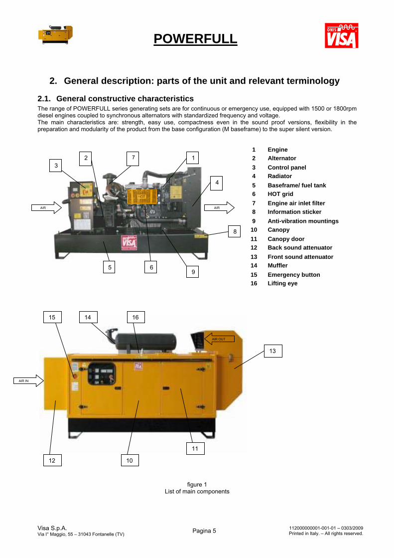
2.1. General constructive characteristics The range of POWERFULL series generating sets are for continuous or emergency use, equipped with 1500 or 1800rpm diesel engines coupled to synchronous alternators with standardized frequency and voltage. The main characteristics are: strength, easy use, compactness even in the sound proof versions, flexibility in the preparation and modularity of the product from the base configuration (M baseframe) to the super silent version.
figure 1 List of main components
1 Engine
2 Alternator
3 Control panel
4 Radiator
5 Baseframe/ fuel tank
6 HOT grid
7 Engine air inlet filter
8 Information sticker
9 Anti-vibration mountings
10 Canopy
11 Canopy door
12 Back sound attenuator
13 Front sound attenuator
14 Muffler
15 Emergency button
16 Lifting eye
12 3
4
5 6
14
11
13
7
8
15
12 10
9
16
AIR IN
AIR AIR
AIR OUT
POWERFULL
Visa S.p.A. Via I° Maggio, 55 – 31043 Fontanelle (TV)
Pagina 6 112000000001-001-01 – 0303/2009Printed in Italy. – All rights reserved.
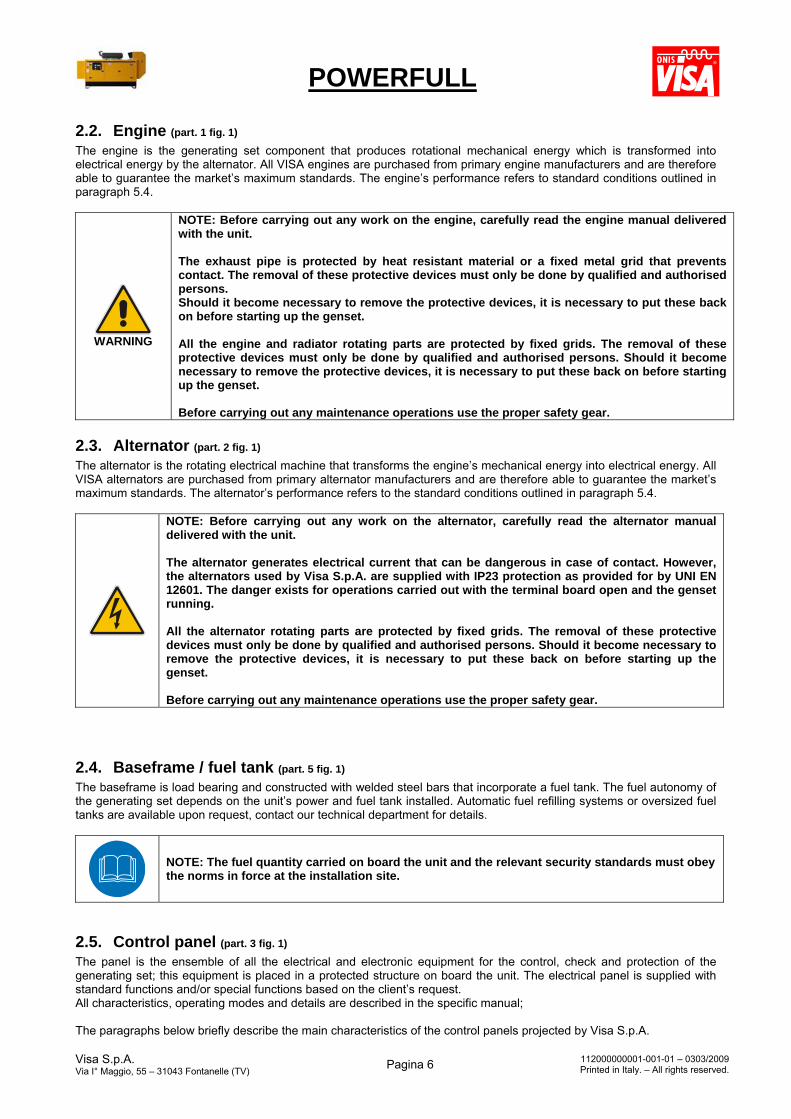
2.2. Engine (part. 1 fig. 1) The engine is the generating set component that produces rotational mechanical energy which is transformed into electrical energy by the alternator. All VISA engines are purchased from primary engine manufacturers and are therefore able to guarantee the market’s maximum standards. The engine’s performance refers to standard conditions outlined in paragraph 5.4.
WARNING
NOTE: Before carrying out any work on the engine, carefully read the engine manual delivered with the unit. The exhaust pipe is protected by heat resistant material or a fixed metal grid that prevents contact. The removal of these protective devices must only be done by qualified and authorised persons. Should it become necessary to remove the protective devices, it is necessary to put these back on before starting up the genset. All the engine and radiator rotating parts are protected by fixed grids. The removal of these protective devices must only be done by qualified and authorised persons. Should it become necessary to remove the protective devices, it is necessary to put these back on before starting up the genset. Before carrying out any maintenance operations use the proper safety gear.
2.3. Alternator (part. 2 fig. 1) The alternator is the rotating electrical machine that transforms the engine’s mechanical energy into electrical energy. All VISA alternators are purchased from primary alternator manufacturers and are therefore able to guarantee the market’s maximum standards. The alternator’s performance refers to the standard conditions outlined in paragraph 5.4.
NOTE: Before carrying out any work on the alternator, carefully read the alternator manual delivered with the unit. The alternator generates electrical current that can be dangerous in case of contact. However, the alternators used by Visa S.p.A. are supplied with IP23 protection as provided for by UNI EN 12601. The danger exists for operations carried out with the terminal board open and the genset running. All the alternator rotating parts are protected by fixed grids. The removal of these protective devices must only be done by qualified and authorised persons. Should it become necessary to remove the protective devices, it is necessary to put these back on before starting up the genset. Before carrying out any maintenance operations use the proper safety gear.
2.4. Baseframe / fuel tank (part. 5 fig. 1) The baseframe is load bearing and constructed with welded steel bars that incorporate a fuel tank. The fuel autonomy of the generating set depends on the unit’s power and fuel tank installed. Automatic fuel refilling systems or oversized fuel tanks are available upon request, contact our technical department for details.
NOTE: The fuel quantity carried on board the unit and the relevant security standards must obey the norms in force at the installation site.
2.5. Control panel (part. 3 fig. 1) The panel is the ensemble of all the electrical and electronic equipment for the control, check and protection of the generating set; this equipment is placed in a protected structure on board the unit. The electrical panel is supplied with standard functions and/or special functions based on the client’s request. All characteristics, operating modes and details are described in the specific manual; The paragraphs below briefly describe the main characteristics of the control panels projected by Visa S.p.A.
POWERFULL
Visa S.p.A. Via I° Maggio, 55 – 31043 Fontanelle (TV)
Pagina 7 112000000001-001-01 – 0303/2009Printed in Italy. – All rights reserved.
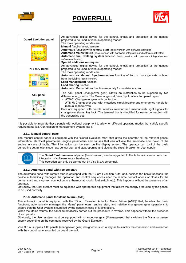
Guard Evolution panel
An advanced digital device for the control, check and protection of the genset, projected to be used in various operating modes; The main operating modes are: Manual function (basic version) Automatic function with remote start (basic version with software activated) Automatic Mains failure (basic version with hardware integration and software activated) Automatic fuel refilling system function (basic version with hardware integration and software activated) Special additions on request
IN-SYNC panel
An advanced digital device for the control, check and protection of the genset, projected to be used in various operating modes; The main operating modes are: Automatic or Manual Synchronisation function of two or more gensets isolated from the Mains (basic version) Load Management function Load sharing function Automatic Mains failure function (especially for parallel operation)
ATS panel
The ATS panel (changeover gear) allows an installation to be supplied by two different energy fonts: The Mains or genset; Visa S.p.A. offers two panel types: - ATS-C: Changeover gear with contactors; - ATS-M: Changeover gear with motorised circuit breaker and emergency handle for
manual manoeuvres. Both are equipped with double interlock (electric and mechanical), light signals for changeover status, key lock. The terminal box is simplified for easier connection with the generating set.
It is possible to integrate these panels with optional equipment to allow for different operating modes that satisfy specific requirements (ex. Connection to management system, etc ).
2.5.1. Manual control panel
The manual control panel is equipped with the “Guard Evolution Man” that gives the operator all the relevant genset information, electrical parameters, engine parameters and causes that can activate the automatic shut down of the engine in case of faults. This information can be seen on the display screen. The operator can control the basic generating set functions such as: genset start and stop, opening and closing the circuit breaker for User supply.
The Guard Evolution manual panel (basic version) can be upgraded to the Automatic version with the integration of software and/or hardware. This operation can only be carried out by Visa S.p.A personnel.
2.5.2. Automatic panel with remote start
The automatic panel with remote start is equipped with the “Guard Evolution Auto” and, besides the basic functions, the device automatically manages the operation and control sequences after the remote contact opens or closes for the genset start and stop (ex. connection to a thermostat, clock, float switch, etc). This happens without the presence of an operator. Obviously, the User system must be equipped with appropriate equipment that allows the energy produced by the genset to be used correctly.
2.5.3. Automatic panel for Mains failure (AMF)
The automatic panel is equipped with the “Guard Evolution Auto for Mains failure (AMF)” that, besides the basic functions, automatically manages the Mains’ parameters, engine start, and relative changeover gear operations to assure that the User system is supplied by the genset in case of Mains failure. When the Mains returns, the panel automatically carries out the procedure in reverse. This happens without the presence of an operator. Obviously, the User system must be equipped with changeover gear (Mains/genset) that switches the Mains or genset supply depending on the command received by the Guard Evolution. Visa S.p.A. supplies ATS panels (changeover gear) designed in such a way as to simplify the connection and interaction with the control panel mounted on board the unit.
POWERFULL
Visa S.p.A. Via I° Maggio, 55 – 31043 Fontanelle (TV)
Pagina 8 112000000001-001-01 – 0303/2009Printed in Italy. – All rights reserved.
2.5.4. Optional functions
Control panels with the “Guard Evolution” card can be equipped with various optional functions through the integration of software or hardware. Listed below are examples of the more important functions: Management software: through a special software and a RS435 serial port converter it is possible to connect a
generating set to a personal computer and carry out all the control and management operations concerning parameters and alarms. It is possible to connect up to 32 generating sets with a limit of 4 units working simultaneously (the multi generating set connection requires accessories to be installed on the Mains; these accessories are NOT included with the software package).
Remote control via GSM or land line: A control and/or check system can be connected to the “Guard Evolution”
that allows the generating set to be managed through special software wherever there is GSM or land line coverage. 20 Alarm card: this supplementary electronic card allows remote monitoring of the alarms or operating status
through relay contacts. Black Box function: The “Guard Evolution” card can be equipped with the “Black Box” function that records and
visualises up to 4000 successive events: status change (ex. from manual to automatic), pre-alarms and alarms indicating the year, month, day, hour, minute and second in which the event took place. Furthermore, the parameter value that caused the block is recorded and in the case of a pre-alarm the length of time it lasted is also recorded. The software allows statistics to be differentiated based on event type: how many starts the generating set had, how many were successful, how many failed; the statistics can be personalised.
Management of fuel refilling system: The “Guard Evolution” card automatically manages the electro-pump
operation for fuel refilling. This function requires the installation of an electro-pump and a 4 level float switch besides the wiring and hydraulic system connection.
Before carrying out any operation on the control panel, carefully read this manual in its entirety and the instruction manual for the Guard Evolution panel delivered together with the unit. For normal generating set use it is not necessary to open the electrical panel; the closed panel guarantees a protection degree of at least IP2X: the electrical panel should be kept locked and opening it must be done by qualified and authorised personnel only. Before carrying out any maintenance on the unit, place it in block, isolate it from the Mains and wait for the engine to cool down.
WARNING
All automatic start modes and those from a distance risk autonomously starting the unit: this situation could place the technician working on the unit or Mains in danger. Before carrying out any maintenance on the unit, (or user connections) put the genset in BLOCK and stop supply to all external energy fonts (Mains survey, pre-heater, battery charger)
2.5.5. Changeover gear ATS-C and ATS-M
The generating set can be connected to an ATS panel that allows the load to be changed from Mains to genset and vice versa. The ATS panels made by Visa S.p.A. are designed in such a way as to simplify the connection and interaction with the Guard Evolution electronic card. Depending on the genset model, panels with contactors or motorised circuit breakers are available.
The ATS panel is supplied with its relative User and Maintenance manual: read the manual carefully before carrying out any operation.
2.5.6. Automatic synchronisation panel isolated from the Mains
The automatic synchronisation panel is equipped with the “In-Sync” control card that allows the operation of two or more generating sets isolated from the Mains to be managed simply. By selecting the “automatic” function of the power station (through operator command or remote signal from a preset cycle) the generating sets will start, synchronise together, supply the User system and load share.
POWERFULL
Visa S.p.A. Via I° Maggio, 55 – 31043 Fontanelle (TV)
Pagina 9 112000000001-001-01 – 0303/2009Printed in Italy. – All rights reserved.
2.5.7. Automatic synchronisation panel paralleling with the Mains
The automatic synchronisation panel is equipped with the “In-Sync” control card that allows the operation of two or more generating sets paralleling with Mains to be managed simply. By selecting the “automatic” function of the power station (through operator command or remote signal from a preset cycle) the following is automatically carried out: generating sets start, parallel with the Mains and load share.
2.5.8. Special panels
Panels made to order per the client’s requirements are available upon request.
2.5.9. Units without electrical equipment or control panel: safety norms.
This paragraph is dedicated to the units requested WITHOUT electrical equipment or with electrical equipment left to be completed by the client. The versions concerned are:
PW000: No electrical equipment PW005: Engine wiring harness only (12V-24V) with relays and terminal box.
For units purchased without a control panel it is advised to use control systems with like characteristics so that after the panel is mounted it continues to guarantee the standards required by D.P.R. 459/96 – MACHINE DIRECTIVE 98/37/CE. It is advised that all electrical equipment used conforms to the standard dictated by European norms or the norms in force at the installation site. The point of reference for generating sets is norm UNI EN 12601.
The MINIMUM requirements for the electrical panel and control system are:
IP protection per the norms in force; Electrical components chosen to tolerate temperature and voltage levels according to norm CEI EN
60204:1998; Control card and electrical components conform to the directive on electromagnetic compatibility CEI EN 61000-
6:2002; The use of checks, control and emergency devices with positive safety: if the control is disconnected or the
signal does not arrive, the control card must block the genset start or disconnect the load and automatically shut down the unit.
Short circuit and overload circuit protection for low voltage; Short circuit and overload circuit protection for very low voltage; Battery connection check: if the connection is interrupted the genset will shut down or not start; Emergency stop
For the sizes listed below, each variation of the nominal value over the set tolerance must generate an interruption in the operation and supply of the energy produced by the generating set:
Voltage generated on the three phases (phase-phase and phase-neutral) with over and under voltage protection and asymmetry;
Current supplied on the three phases with over current protection; Frequency / rpm with over and under speed protection; Cooling liquid temperature with high temperature protection; Oil pressure with low pressure protection; Battery voltage with over and under voltage protection; Missed voltage supply by the alternator
2.6. Canopy (part. 10 fig. 1) The Powerfull series generating sets in the “M” version are designed to allow the transformation from open to cover and/or soundproof version even after purchase. There are 6 canopy sizes available called C10, C20, C30, C40, C50 and C60 that can be equipped with different types of sound attenuators (C, S, SS) that offer protection against bad weather and noise level attenuation.
Canopy abbreviation
Characteristics Nominal noise reduction with reference to open units in the
M – B – U versions
C COVER version: designed for gensets ranging from 10 to 2000 kVA guaranteeing bad weather protection and noise level attenuation.
- approximately 8 dB(A)
S SILENT version: designed for gensets ranging from 10 to 130 kVA - approximately 15 dB(A)
POWERFULL
Visa S.p.A. Via I° Maggio, 55 – 31043 Fontanelle (TV)
Pagina 10 112000000001-001-01 – 0303/2009Printed in Italy. – All rights reserved.
guaranteeing protection and noise level attenuation.
SS SUPER SILENT version: designed for gensets ranging from 10 to 2000 kVA guaranteeing protection and noise level attenuation.
- approximately 20 dB(A)
When the genset is operating it is necessary to keep the canopy locked seeing that it constitutes a means of protection. Opening the canopy must only be done by qualified and authorised persons. NOTE: the canopy is not designed for access while the unit is in operation.
2.7. Mufflers
2.7.1. Exhaust mufflers (part. 14 fig. 1)
The S and SS canopies are supplied with semi residential muffler type MSRa. The Powerfull series generating sets in the M, B and C versions are all equipped with industrial type muffler MS.
Unit version Muffler type Performance in
dB(A) Accessories Assembly
M, B, C MS 15 ca. Expansion coupling Supplied loose, client to
assemble
S, SS MSRa 28-30 ca. Expansion coupling Already assembled at time
of delivery
The person(s) who carry(ies) out the exhaust connections and conduit work on the installation must guarantee that the exhaust gas exits are always placed externally and in position according to the law. Accessories for the correct installation of the exhaust conduit can be supplied on request, for example: flanges, supports, rain cap or other accessories.
For exhaust back pressure values and fume extraction modes see the engine technical data sheet and installation chapter in this manual.
2.7.2. Sound attenuators (part. 12-13 fig. 1)
These are canopy appendages, realised with the same principles and methods as the canopies. Three canopy models are available based on function, C – S – SS. In the SS version the top sound attenuator turns 180° and can act as an air expulsion conduit in an indoor installation.
2.8. Transport Trailer The transport trailers are single or double axle that allow the generating set to be hitched onto a vehicle and towed on the road. VISA S.p.A. has two types of trailer:
Homologated trailers for transport on public roads; Non-homologated trailer, suitable for slow haulage on private roads and no through traffic zones;
For transport trailer use consult chapter 4 of this manual, Moving the generating set Warning: for applications in markets where regulations are in force for mobile use (including the European Community) it is obligatory to use units that comply with the noise emission and exhaust emission norms.
POWERFULL
Visa S.p.A. Via I° Maggio, 55 – 31043 Fontanelle (TV)
Pagina 11 112000000001-001-01 – 0303/2009Printed in Italy. – All rights reserved.
3. Danger zones and safety gear To avoid exposing personnel to potentially dangerous situations, it is advised that maintenance interventions be carried out with the control panel in block mode, engine cooled, generating set and accessories isolated from the Mains and by qualified persons. Reminder: Compliance with all safety measures are the client’s responsibility.
Safety shoes must be worn before carrying out any work on the generating set in order to avoid slipping and accidental contact with hot or rotating parts on the unit.
Close fitting clothing must be worn before carrying out any work on the generating set in order to avoid entanglement with any rotating parts.
Safety gloves must be worn before carrying out any work on the generating set in order to avoid contact with the unit’s hot parts or dangerous liquids.
Safety glasses must be worn before carrying out any work on the generating set: These are necessary to avoid eye injury caused by expelled fluid or parts.
Hearing protection must be worn before approaching a generating set: NOTE: open units can reach noise levels that may create permanent hearing damage after long periods of exposure. The exact calculation of the equivalent noise exposure level (for all exposed personnel) is the responsibility of the buyer.
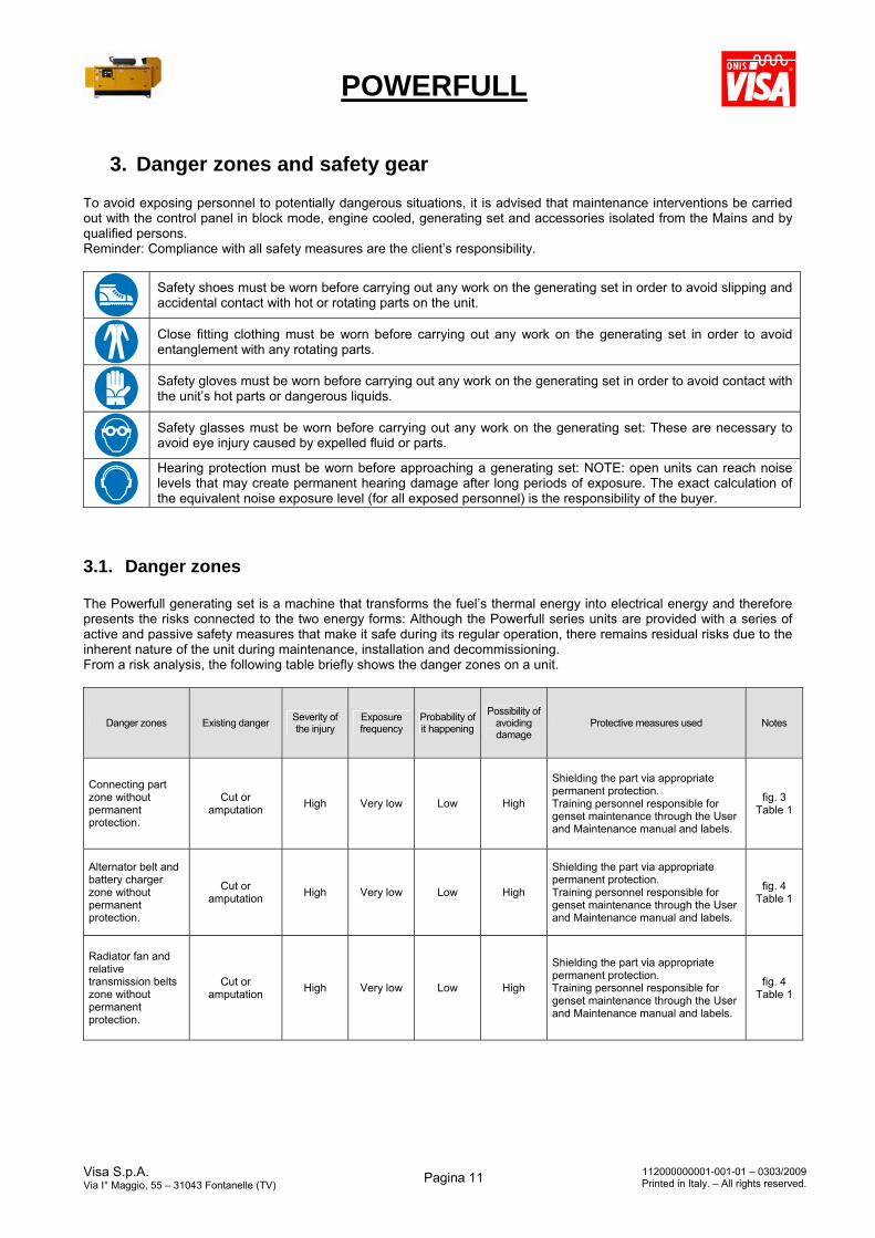
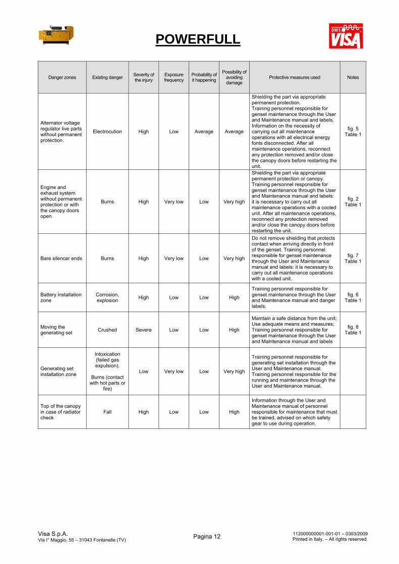
3.1. Danger zones The Powerfull generating set is a machine that transforms the fuel’s thermal energy into electrical energy and therefore presents the risks connected to the two energy forms: Although the Powerfull series units are provided with a series of active and passive safety measures that make it safe during its regular operation, there remains residual risks due to the inherent nature of the unit during maintenance, installation and decommissioning. From a risk analysis, the following table briefly shows the danger zones on a unit.
Danger zones Existing danger Severity of the injury
Exposure frequency
Probability of it happening
Possibility of avoiding damage
Protective measures used Notes
Connecting part zone without permanent protection.
Cut or amputation
High Very low Low High
Shielding the part via appropriate permanent protection. Training personnel responsible for genset maintenance through the User and Maintenance manual and labels.
fig. 3 Table 1
Alternator belt and battery charger zone without permanent protection.
Cut or amputation
High Very low Low High
Shielding the part via appropriate permanent protection. Training personnel responsible for genset maintenance through the User and Maintenance manual and labels.
fig. 4 Table 1
Radiator fan and relative transmission belts zone without permanent protection.
Cut or amputation
High Very low Low High
Shielding the part via appropriate permanent protection. Training personnel responsible for genset maintenance through the User and Maintenance manual and labels.
fig. 4 Table 1
POWERFULL
Visa S.p.A. Via I° Maggio, 55 – 31043 Fontanelle (TV)
Pagina 12 112000000001-001-01 – 0303/2009Printed in Italy. – All rights reserved.
Danger zones Existing danger Severity of the injury
Exposure frequency
Probability of it happening
Possibility of avoiding damage
Protective measures used Notes
Alternator voltage regulator live parts without permanent protection.
Electrocution High Low Average Average
Shielding the part via appropriate permanent protection. Training personnel responsible for genset maintenance through the User and Maintenance manual and labels. Information on the necessity of carrying out all maintenance operations with all electrical energy fonts disconnected. After all maintenance operations, reconnect any protection removed and/or close the canopy doors before restarting the unit.
fig. 5 Table 1
Engine and exhaust system without permanent protection or with the canopy doors open.
Burns High Very low Low Very high
Shielding the part via appropriate permanent protection or canopy. Training personnel responsible for genset maintenance through the User and Maintenance manual and labels: it is necessary to carry out all maintenance operations with a cooled unit. After all maintenance operations, reconnect any protection removed and/or close the canopy doors before restarting the unit.
fig. 2 Table 1
Bare silencer ends Burns High Very low Low Very high
Do not remove shielding that protects contact when arriving directly in front of the genset. Training personnel responsible for genset maintenance through the User and Maintenance manual and labels: it is necessary to carry out all maintenance operations with a cooled unit.
fig. 7 Table 1
Battery installation zone
Corrosion, explosion
High Low Low High
Training personnel responsible for genset maintenance through the User and Maintenance manual and danger labels.
fig. 6 Table 1
Moving the generating set
Crushed Severe Low Low High
Maintain a safe distance from the unit; Use adequate means and measures; Training personnel responsible for genset maintenance through the User and Maintenance manual and labels
fig. 8 Table 1
Generating set installation zone
Intoxication (failed gas expulsion).
Burns (contact
with hot parts or fire)
Low Very low Low Very high
Training personnel responsible for generating set installation through the User and Maintenance manual. Training personnel responsible for the running and maintenance through the User and Maintenance manual.
Top of the canopy in case of radiator check
Fall High Low Low High
Information through the User and Maintenance manual of personnel responsible for maintenance that must be trained, advised on which safety gear to use during operation.
POWERFULL
Visa S.p.A. Via I° Maggio, 55 – 31043 Fontanelle (TV)
Pagina 13 112000000001-001-01 – 0303/2009Printed in Italy. – All rights reserved.
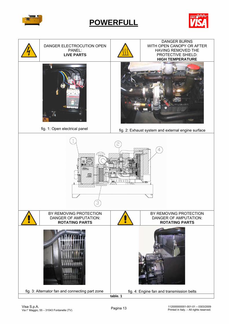
DANGER ELECTROCUTION OPEN PANEL:
LIVE PARTS
DANGER BURNS WITH OPEN CANOPY OR AFTER
HAVING REMOVED THE PROTECTIVE SHIELD: HIGH TEMPERATURE
fig. 1: Open electrical panel
fig. 2: Exhaust system and external engine surface
BY REMOVING PROTECTION DANGER OF AMPUTATION:
ROTATING PARTS
BY REMOVING PROTECTION DANGER OF AMPUTATION:
ROTATING PARTS
fig. 3: Alternator fan and connecting part zone
fig. 4: Engine fan and transmission belts table. 1
POWERFULL
Visa S.p.A. Via I° Maggio, 55 – 31043 Fontanelle (TV)
Pagina 14 112000000001-001-01 – 0303/2009Printed in Italy. – All rights reserved.
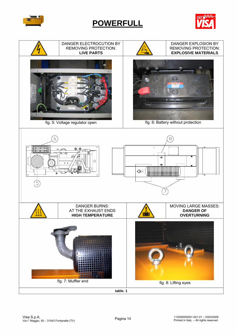
DANGER ELECTROCUTION BY REMOVING PROTECTION:
LIVE PARTS
DANGER EXPLOSION BY REMOVING PROTECTION: EXPLOSIVE MATERIALS
fig. 5: Voltage regulator open
fig. 6: Battery without protection
DANGER BURNS: AT THE EXHAUST ENDS
HIGH TEMPERATURE
MOVING LARGE MASSES: DANGER OF
OVERTURNING
fig. 7: Muffler end
fig. 8: Lifting eyes
table. 1
POWERFULL
Visa S.p.A. Via I° Maggio, 55 – 31043 Fontanelle (TV)
Pagina 15 112000000001-001-01 – 0303/2009Printed in Italy. – All rights reserved.
4. Moving the generating set Per European directives, the standard Powerfull units are equipped with lifting points to be used when loading and unloading the unit. However, the lifting points on the standard Powerfull unit does not exclude the fact that it is projected for permanent installation (non-mobile use); Each unit’s information tag reports kilos and its mass (with full fuel tank and all liquids topped up).
When moving/lifting a genset it is imperative to be extremely careful. All moving operations must be carried out be qualified persons. Due to the weight and encumbrance of the genset, an error while moving/lifting the unit may cause serious damage to it or surrounding persons.
4.1. General precautions for moving the unit To limit the dangers involved in moving a generating set, it is important to carefully follow the guidelines set out below:
Transportation must always take place with the engine off and unit in block mode, electrical cables and starting battery disconnected and fuel tank empty.
Particular attention must be paid to M and B version generating sets (without canopy) that have very delicate parts unprotected from bumps (injection pump, speed regulator, radiator, electrical panel connections and instrumentation).
Generating sets must be protected from bad weather during transport: the units must be entirely covered, especially the electrical parts (alternator and control panel).
Some engine parts retain heat even after the unit has been shut off: therefore it is necessary to wait for the engine to cool before covering it to avoid the risk of fire.
Clear the moving zone of all possible obstacles and from all unnecessary personnel; Always use properly sized lifting equipment inspected by a licensed organisation; it is prohibited to fasten
objects or accessories onto the generating set baseframe that make the unit heavy and subject it to movements unforeseen by the lifting eyes.
Do not subject the generating set and lifting equipment to abrupt or undulating movements that pass on stress dynamics to the structure;
Do not lift the generating set higher than what is absolutely necessary. Transportation of separate manual or automatic control panels must be carried out very carefully in order to
avoid damage to the equipment contained inside the panel and to the instruments on the front. To access the hook points on the top of the unit, use approved ladders only or support from another operator:
climb the ladder using non-skid shoes.
4.2. Moving method The generating sets are lifted with different methods according to the unit’s configuration. Below are the main methods of moving/lifting the genset.
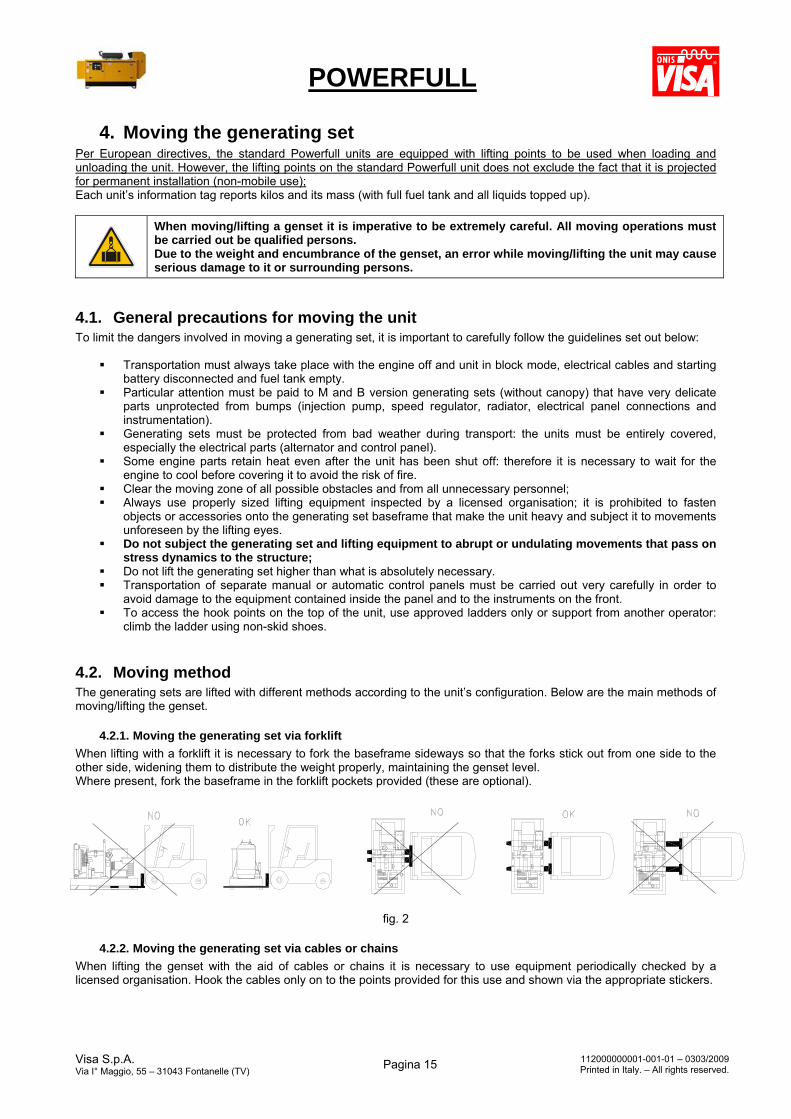
4.2.1. Moving the generating set via forklift
When lifting with a forklift it is necessary to fork the baseframe sideways so that the forks stick out from one side to the other side, widening them to distribute the weight properly, maintaining the genset level. Where present, fork the baseframe in the forklift pockets provided (these are optional).
fig. 2
4.2.2. Moving the generating set via cables or chains
When lifting the genset with the aid of cables or chains it is necessary to use equipment periodically checked by a licensed organisation. Hook the cables only on to the points provided for this use and shown via the appropriate stickers.
POWERFULL
Visa S.p.A. Via I° Maggio, 55 – 31043 Fontanelle (TV)
Pagina 16 112000000001-001-01 – 0303/2009Printed in Italy. – All rights reserved.
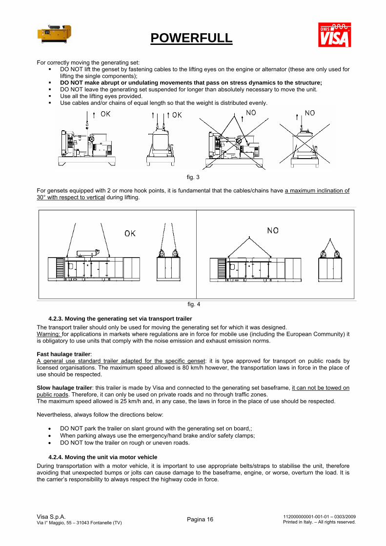
For correctly moving the generating set: DO NOT lift the genset by fastening cables to the lifting eyes on the engine or alternator (these are only used for
lifting the single components); DO NOT make abrupt or undulating movements that pass on stress dynamics to the structure; DO NOT leave the generating set suspended for longer than absolutely necessary to move the unit. Use all the lifting eyes provided. Use cables and/or chains of equal length so that the weight is distributed evenly.
fig. 3
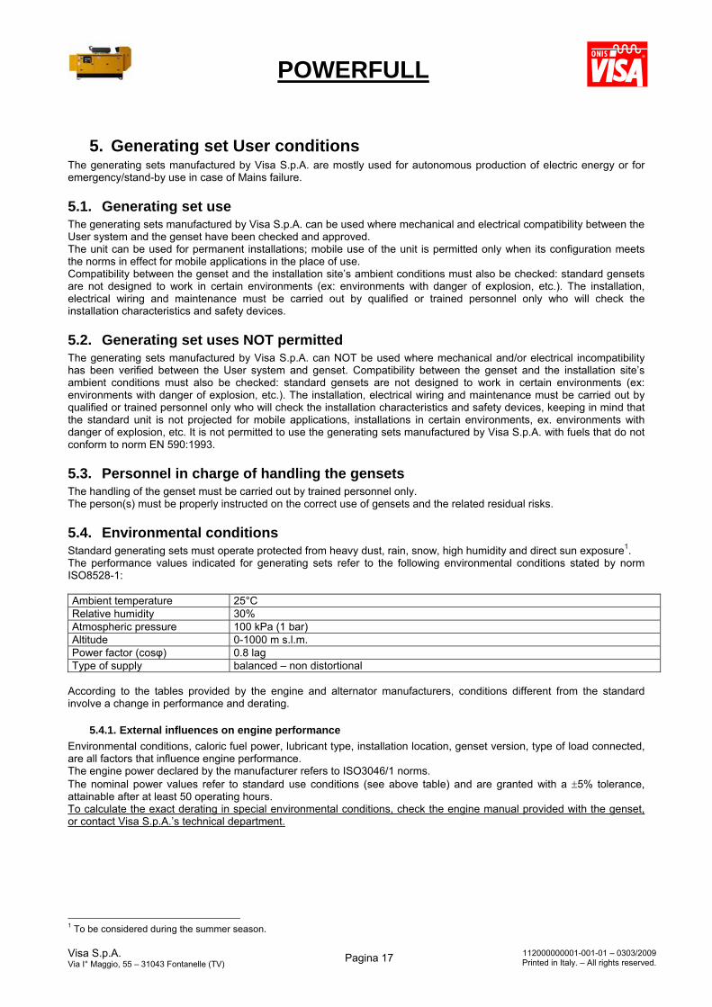
For gensets equipped with 2 or more hook points, it is fundamental that the cables/chains have a maximum inclination of 30° with respect to vertical during lifting.
fig. 4
4.2.3. Moving the generating set via transport trailer
The transport trailer should only be used for moving the generating set for which it was designed. Warning: for applications in markets where regulations are in force for mobile use (including the European Community) it is obligatory to use units that comply with the noise emission and exhaust emission norms. Fast haulage trailer: A general use standard trailer adapted for the specific genset: it is type approved for transport on public roads by licensed organisations. The maximum speed allowed is 80 km/h however, the transportation laws in force in the place of use should be respected. Slow haulage trailer: this trailer is made by Visa and connected to the generating set baseframe, it can not be towed on public roads. Therefore, it can only be used on private roads and no through traffic zones. The maximum speed allowed is 25 km/h and, in any case, the laws in force in the place of use should be respected. Nevertheless, always follow the directions below:
DO NOT park the trailer on slant ground with the generating set on board,; When parking always use the emergency/hand brake and/or safety clamps; DO NOT tow the trailer on rough or uneven roads.
4.2.4. Moving the unit via motor vehicle
During transportation with a motor vehicle, it is important to use appropriate belts/straps to stabilise the unit, therefore avoiding that unexpected bumps or jolts can cause damage to the baseframe, engine, or worse, overturn the load. It is the carrier’s responsibility to always respect the highway code in force.
POWERFULL
Visa S.p.A. Via I° Maggio, 55 – 31043 Fontanelle (TV)
Pagina 17 112000000001-001-01 – 0303/2009Printed in Italy. – All rights reserved.
5. Generating set User conditions The generating sets manufactured by Visa S.p.A. are mostly used for autonomous production of electric energy or for emergency/stand-by use in case of Mains failure.
5.1. Generating set use The generating sets manufactured by Visa S.p.A. can be used where mechanical and electrical compatibility between the User system and the genset have been checked and approved. The unit can be used for permanent installations; mobile use of the unit is permitted only when its configuration meets the norms in effect for mobile applications in the place of use. Compatibility between the genset and the installation site’s ambient conditions must also be checked: standard gensets are not designed to work in certain environments (ex: environments with danger of explosion, etc.). The installation, electrical wiring and maintenance must be carried out by qualified or trained personnel only who will check the installation characteristics and safety devices.
5.2. Generating set uses NOT permitted The generating sets manufactured by Visa S.p.A. can NOT be used where mechanical and/or electrical incompatibility has been verified between the User system and genset. Compatibility between the genset and the installation site’s ambient conditions must also be checked: standard gensets are not designed to work in certain environments (ex: environments with danger of explosion, etc.). The installation, electrical wiring and maintenance must be carried out by qualified or trained personnel only who will check the installation characteristics and safety devices, keeping in mind that the standard unit is not projected for mobile applications, installations in certain environments, ex. environments with danger of explosion, etc. It is not permitted to use the generating sets manufactured by Visa S.p.A. with fuels that do not conform to norm EN 590:1993.
5.3. Personnel in charge of handling the gensets The handling of the genset must be carried out by trained personnel only. The person(s) must be properly instructed on the correct use of gensets and the related residual risks.
5.4. Environmental conditions Standard generating sets must operate protected from heavy dust, rain, snow, high humidity and direct sun exposure1. The performance values indicated for generating sets refer to the following environmental conditions stated by norm ISO8528-1: Ambient temperature 25°C Relative humidity 30% Atmospheric pressure 100 kPa (1 bar) Altitude 0-1000 m s.l.m. Power factor (cosφ) 0.8 lag Type of supply balanced – non distortional
According to the tables provided by the engine and alternator manufacturers, conditions different from the standard involve a change in performance and derating.
5.4.1. External influences on engine performance
Environmental conditions, caloric fuel power, lubricant type, installation location, genset version, type of load connected, are all factors that influence engine performance. The engine power declared by the manufacturer refers to ISO3046/1 norms. The nominal power values refer to standard use conditions (see above table) and are granted with a 5% tolerance, attainable after at least 50 operating hours. To calculate the exact derating in special environmental conditions, check the engine manual provided with the genset, or contact Visa S.p.A.’s technical department.
1 To be considered during the summer season.

POWERFULL
Visa S.p.A. Via I° Maggio, 55 – 31043 Fontanelle (TV)
Pagina 18 112000000001-001-01 – 0303/2009Printed in Italy. – All rights reserved.
The type of fuel used has an important role on engine performance and duration. For engines bought from Visa S.p.A. it is advised to use fuels that conform to norm EN 590:1993 only. Before using bio-fuel or any other fuel of organic origin, or other substances, even if diluted at a low percentage, it is necessary to obtain authorization from the engine manufacturer, otherwise the warranty will be void.
5.4.2. External influences on alternator performance
The synchronous alternator’s power declared by the manufacturer refers to norm IEC34-1 and when coupled to an engine creating a generating set, to norm ISO8528-3. The winding’s operating temperature, environmental conditions, installation location, type of User system, its power factor and IP protection level, are all values that influence the alternator’s performance. Conditions different from those stated cause performance variations and derating per the table below:
Table of corrective factors for altitude and temperature:
Altitude/Temperature 25°C 40°C 45°C 50°C 55°C 1000 m 1.09 1 0.96 0.93 0.91 from 1000 to 1500 m 1.01 0.96 0.92 0.89 0.87 from 1500 to 2000 m 0.96 0.91 0.87 0.84 0.83 from 2000 to 3000 m 0.90 0.85 0.81 0.78 0.76
The generating sets supplied by Visa S.p.A. are sized to work in standard conditions with cos = 0.8. As shown in the table below, if the load’s cos is close to 1.0, the engine is shown as overloaded; if the load is mainly inductive (cos<0.8) the alternator’s excitation system will be overloaded, while the engine is seen as over-sized. The solution usually used to avoid the above is to correct the system’s power factor with the appropriate techniques (i.e. an automatic power factor corrector) in order to reach the correct values. To feed loads with a cos that is not standard, contact Visa S.p.A.’s technical department.
Table of corrective factors for delayed power factor (cos):
Cos 1 0.8 0.7 0.6 0.5 0.3 0 Factor 1 1 0.93 0.88 0.84 0.82 0.8
5.5. Generating set power values ISO 8528-1:1993 norm considers and defines three categories for the type of use for which the genset is subjected to considering that the genset is operating under controlled environmental conditions according to norm ISO 3046-1:1995 for engines and norm IEC 34-1 for alternators (per the previous section, special environmental conditions are a source of engine and alternator derating). Here below are the three categories defined by these norms:
1) CONTINUOUS POWER (C.O.P.) It is the continuous power that the genset can supply continuously for an unlimited number of hours between the set maintenance intervals. A 10% overload is permitted for regulating purposes only. 2) PRIME POWER (P.R.P.)
It is the maximum power available for a cycle of variable power that the genset can supply continuously for an unlimited number of hours between the set maintenance intervals. The average power supply that can be used during a 24 hour period must not exceed 80% of the P.R.P. A 10% overload is permitted for rating only (on some genset models the acceptable overload may be 5%).
3) LIMITED TIME RUNNING POWER (L.T.P.)
It is the maximum power that a genset can provide for up to a maximum of 500 hours per year, of which 300 hours continuous operation between maintenance intervals. A 10% overload is permitted for rating only.
The rated output and performance of standard Powerfull generating sets conform to norm ISO 8528-1:1993 according to category P.R.P.
POWERFULL
Visa S.p.A. Via I° Maggio, 55 – 31043 Fontanelle (TV)
Pagina 19 112000000001-001-01 – 0303/2009Printed in Italy. – All rights reserved.
6. Load conditions
6.1. User system The correct operation of the Powerfull can be affected by the equipment that needs to be fed; there are User systems that are compatible only if the power is less than the generating set’s nominal power, therefore the supply should be carefully checked.
All generating sets manufactured by Visa S.p.A. are equipped with a voltage control system, able to regulate and block the unit if the values differ from nominal conditions. In order to avoid unexpected blackouts, carefully follow the indications below relative to load type.
When feeding a single-phase or unbalanced load, the tolerance on the voltage supplied is not guaranteed and abnormal vibrations may occur on the alternator; therefore this type of use is not advised. However, SINGLE-PHASE loads are allowed on three-phase alternators as long as the power value requested does not exceed 1/3 of unit’s rated output on each phase.
6.1.1. Non-linear loads
The most common non-linear loads on a three-phase system are those controlled by a thyristor/rectifier, such as static six-phase or twelve-phase converters, devices used for asynchronous engine control (soft-start), uninterruptible power supply devices such as UPS, equipment provided with SCR, direct current engines. Lighting systems with gas discharge lamps also create high frequency harmonics, creating a risk of high neutral current. In case the installation system has not been checked, a detailed sizing analysis before genset start-up is recommended.
Non-linear loads absorb currents with high level harmonic frequencies, producing distortional waves on the voltage generated by the alternator. These can cause a malfunction on the regulation system and an uncontrolled rise in voltage, damaging the generating set’s alternator and connected equipment.
6.1.2. Resistive loads (bulbs, heaters, resistances, etc.)
A Powerfull genset can also take on pure resistive loads, but with compound alternators there may be an increase in the operational voltage. When using a Powerfull genset with pure resistive load, consider that apparent power (kVA) equals effective power (kW) (as the cos is 1.0), therefore electric load has to be 20% less than nominal power in kVA. Warning: resistive loads are usually single-phase, check that the load on each phase does not exceed 1/3 of rated output.
6.1.3. Capacitive loads (condensers, discharge lamps, X-ray equipment, etc.)
It is very unlikely to find a purely capacitive load. This type of equipment is usually used with non-automatic power factor correction systems; the presence of distortional equipment on the supply system should also be checked.
A purely capacitive load increases the voltage produced by the genset over the tolerance limits set, creating possible damage to the alternator and to the user system connected to it. Particular attention must be paid towards devices with capacitive effects, such as soft-start devices, static welding set and discharge lamps, as these are often not compatible with gensets. A genset can supply a capacitive load for a maximum value corresponding to 20% of the rated output of the alternator, but the tolerances on the voltage output cannot be guaranteed.
In order to avoid the above mentioned problems, the power factor correction capacity should be calculated on phase displacement (ex: electric engines with condenser, neon lights with locally corrected power factor, automatic power factor correctors).
6.1.4. Inductive load (electric engines in general, electric fans, motor pumps, winches, etc.)
Electric engines, especially those with a cage rotor, have a very high current value during start-up (up to 10 times the rated current 2) combined with a low power factor.
2 Special attention should be paid to the engines installed on lifts and winches in general.
POWERFULL
Visa S.p.A. Via I° Maggio, 55 – 31043 Fontanelle (TV)
Pagina 20 112000000001-001-01 – 0303/2009Printed in Italy. – All rights reserved.
Generally alternators mounted on Powerfull gensets are able to supply an output current equal to 2.5 times the rated current for a max of 10-15 seconds. This period is usually sufficient to start cage engines with a transient voltage droop of 35% (that decreases within 0.15-0.30 seconds to 15%). As soon as the engine or electric engines are started, the absorbed power will normalize and it will be possible to start the other devices in the User system in sequence. All these values must be considered by the User when sizing the genset. There are several methods used In order to avoid over-sizing due to starting current, even when this type of User system is fed by the Mains. Device examples with the function of decreasing the starting current are: delta-star system, system with wound rotor and rheostatic starter or the modern soft-start system (where compatibility must be checked with the manufacturer for the above mentioned reasons). The power relation between a Powerfull genset and the electric engine to be started can vary depending on the acceptable voltage droop for the equipment fed during start-up.
6.2. Load application The maximum load that can be applied to a genset in one step (ex: starting of an electric fan or a motor pump, etc.), depends mainly on the engine’s characteristics, such as displacement, torque, inertia, regulation system, and supercharging devices. The current trend is to manufacture engines with high output by decreasing displacement, this is a disadvantage for engine load absorbing capacity.
It is very important to know in advance if the load to be supplied will be inserted gradually or in one step. This information is necessary to identify the correct genset model.
Generally, it can be said that (there may be important variations depending on engine characteristics):
Aspirated engines can take a load step equal to 100% of continuous power, with a variation of temporary speed of ≤ 10%;
Turbo engines can take a load step equal to 40-50% of continuous power, with a variation of temporary speed of ≤ 10%;
For further details check the engine manual provided with the genset or contact Visa S.p.A.
A prolonged use of the genset at less than 30% of the rated output causes premature wear of engine components. For further details check engine manual.
6.3. Connections to alternator Alternators used on Powerfull gensets are three-phase with neutral and can supply (with limitations) three-phase and single-phase loads at the same time. Standard alternator can be with six or twelve terminals depending on its voltage: With six terminals, windings can be star-type, triangle-type or zig-zag-type. With twelve terminals, in addition to the standard star-series connection the following can be added: star-parallel with neutral, triangle-serial, triangle-parallel, zig-zag, zig-zag-parallel and double-delta connections; for further information referring to obtainable power contact Visa S.p.A.
6.3.1. Star connection (sample of standard supply)
When a three-phase alternator, at 50 Hz, has a star-connection, it supplies a standard voltage of 400V between phases and 230V between each phase and neutral. For load distribution follow below instructions:
Usable power between phase and neutral (voltage 230V) should never exceed 1/3 of rated output; Usable power between phases (voltage 400V) should never exceed 2/3 of rated output;
Genset output and connection type must be defined when ordering genset. If it were necessary to modify these parameters, only a Visa S.p.A. technician with the appropriate software could carry out the changes.
POWERFULL
Visa S.p.A. Via I° Maggio, 55 – 31043 Fontanelle (TV)
Pagina 21 112000000001-001-01 – 0303/2009Printed in Italy. – All rights reserved.
6.3.2. Cyclical phase direction
Cyclical phase sequence is R, S, T
Before connecting a Powerfull genset to the User system, the cyclical direction must be checked with a specific instrument. Machinery may endure serious damage in case of inverted direction. This verification has to be carried out by a qualified technician.
7. Installation instructions
7.1. General installation principles The installation of a genset must be designed and planned by qualified and trained technicians. This must be carried out by a competent organization with qualified personnel and proper equipment. The initial genset start-up must be carried out by a qualified technician authorised by Visa S.p.A.
Faulty installation may create damage to the genset and User system as well as injury to persons. It is compulsory to install the genset according to the norms in force in the country of installation. The contractor must provide a conformity declaration stating that installation has been carried out duly and according to plans and norms in force.
Before proceeding with the installation the following conditions must be checked:
That the genset has been selected according to the electrical load needs and to environmental conditions (temperature, altitude and humidity)
That the electrical equipment and control panel, if supplied with the genset, are according to Visa S.p.A.’s instructions, European norms in force and genset specifications;
That the genset location is of appropriate size and allows accessibility to the genset for maintenance and/or necessary repairs;
If the genset is indoors, ensure there is enough air for engine combustion, for genset cooling (radiator and generator) and sufficient ventilation;
If the genset is indoors, a system of expulsion for engine exhaust gas is provided; Personnel safety has been carefully considered; Noise-level issues have been carefully considered; Fuel and lubricant storage issues have been considered in accordance to the norms in force in the country of
installation.
Italian and European norms define specific characteristics referring to the premises in which the genset should be located, indicating possible positioning, minimum dimensions, etc. Contact Visa S.p.A. for further installation information.
7.2. Outdoor installation
All Visa S.p.A. generating sets are equipped with a control system that is NOT influenced by standard environmental factors and is able to stop the unit in case of inconsistent values in the basic parameters. In order to avoid unexpected black-outs or other potentially dangerous situations, the installation instructions listed below must be followed.
7.2.1. Environmental conditions
Open gensets (version M, B and U) have to be located in an area protected from rain, snow, high humidity and direct exposure to the sun. Rain or high humidity on the Powerfull genset alternator, especially during operation, can cause an increase in voltage output, winding faults or electric discharge towards ground with damage to the genset and injury to persons. Dust, in particular saline dust, must be avoided. In case radiator or air filters are obstructed, there is the risk that the genset will overheat or be damaged. Aspiration grills on silencers and on the baseframe must not be obstructed by leaves, snow, etc. The baseframe must never be underwater, not even partially, or else water may damage genset.
POWERFULL
Visa S.p.A. Via I° Maggio, 55 – 31043 Fontanelle (TV)
Pagina 22 112000000001-001-01 – 0303/2009Printed in Italy. – All rights reserved.
7.2.2. Output of fumes in open air conditions
The genset must be positioned so that the exhaust gas is diffused without being inhaled by anyone. Engine exhaust gas contains carbon monoxide which is harmful to one’s health and in large quantities can cause intoxication and death. Local norms in force must be respected.
7.2.3. Safe distance
A safe distance must be kept between the genset and fuel deposits, flammable goods (cloths, paper, etc.) and chemicals according to the instructions provided by the authority in charge. In order to avoid potentially dangerous situations, the area surrounding the genset should be isolated so that unauthorized persons can not access the unit. Even if Visa S.p.A. gensets are manufactured according to electromagnetic compatibility norms, we suggest that the genset NOT be installed near machinery that can be influenced by magnetic fields.
7.2.4. Installing
In order to absorb the vibrations produced by genset, the unit should be fixed to a rigid surface, isolated from vibrations towards other structures and with a mass equal to at least three times that of the genset. DO NOT put the genset on terraces or raised levels if the characteristics have not been previously verified and deemed suitable.
WARNING: if a genset is located outdoors it is necessary to take precautions so that no fuel, lubricant, or other liquid spills into the ground.
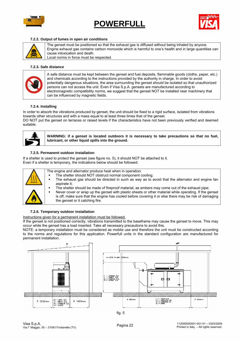
7.2.5. Permanent outdoor installation
If a shelter is used to protect the genset (see figure no. 5), it should NOT be attached to it. Even if a shelter is temporary, the indications below should be followed:
The engine and alternator produce heat when in operation. The shelter should NOT obstruct normal component cooling; The exhaust gas should be directed in such as way as to avoid that the alternator and engine fan
aspirate it; The shelter should be made of fireproof material, as embers may come out of the exhaust pipe; Never cover or wrap up the genset with plastic sheets or other material while operating. If the genset
is off, make sure that the engine has cooled before covering it or else there may be risk of damaging the genset or it catching fire.
7.2.6. Temporary outdoor installation
Instructions given for a permanent installation must be followed. If the genset is not positioned correctly, vibrations transmitted to the baseframe may cause the genset to move. This may occur while the genset has a load inserted. Take all necessary precautions to avoid this. NOTE: a temporary installation must be considered as moblie use and therefore the unit must be constructed according to the norms and regulations for this application. Powerfull units in the standard configuration are manufactured for permanent installation.
fig. 5
POWERFULL
Visa S.p.A. Via I° Maggio, 55 – 31043 Fontanelle (TV)
Pagina 23 112000000001-001-01 – 0303/2009Printed in Italy. – All rights reserved.
Sample of outdoor installation with shelter
7.3. Indoor installation In order to avoid jeopardising or damaging the genset, follow the instructions below. Genset installation location must be in accordance to the norms in force.
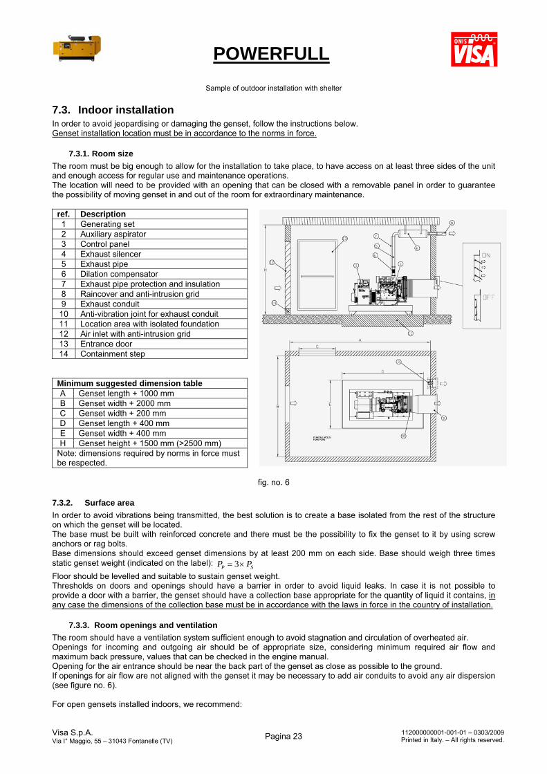
7.3.1. Room size
The room must be big enough to allow for the installation to take place, to have access on at least three sides of the unit and enough access for regular use and maintenance operations. The location will need to be provided with an opening that can be closed with a removable panel in order to guarantee the possibility of moving genset in and out of the room for extraordinary maintenance.
fig. no. 6
7.3.2. Surface area
In order to avoid vibrations being transmitted, the best solution is to create a base isolated from the rest of the structure on which the genset will be located. The base must be built with reinforced concrete and there must be the possibility to fix the genset to it by using screw anchors or rag bolts. Base dimensions should exceed genset dimensions by at least 200 mm on each side. Base should weigh three times static genset weight (indicated on the label):
SP PP 3
Floor should be levelled and suitable to sustain genset weight. Thresholds on doors and openings should have a barrier in order to avoid liquid leaks. In case it is not possible to provide a door with a barrier, the genset should have a collection base appropriate for the quantity of liquid it contains, in any case the dimensions of the collection base must be in accordance with the laws in force in the country of installation.
7.3.3. Room openings and ventilation
The room should have a ventilation system sufficient enough to avoid stagnation and circulation of overheated air. Openings for incoming and outgoing air should be of appropriate size, considering minimum required air flow and maximum back pressure, values that can be checked in the engine manual. Opening for the air entrance should be near the back part of the genset as close as possible to the ground. If openings for air flow are not aligned with the genset it may be necessary to add air conduits to avoid any air dispersion (see figure no. 6). For open gensets installed indoors, we recommend:
ref. Description 1 Generating set 2 Auxiliary aspirator 3 Control panel 4 Exhaust silencer 5 Exhaust pipe 6 Dilation compensator 7 Exhaust pipe protection and insulation 8 Raincover and anti-intrusion grid 9 Exhaust conduit 10 Anti-vibration joint for exhaust conduit 11 Location area with isolated foundation 12 Air inlet with anti-intrusion grid 13 Entrance door 14 Containment step
Minimum suggested dimension table A Genset length + 1000 mm B Genset width + 2000 mm C Genset width + 200 mm D Genset length + 400 mm E Genset width + 400 mm H Genset height + 1500 mm (>2500 mm)
Note: dimensions required by norms in force must be respected.
POWERFULL
Visa S.p.A. Via I° Maggio, 55 – 31043 Fontanelle (TV)
Pagina 24 112000000001-001-01 – 0303/2009Printed in Italy. – All rights reserved.
Dimensions of the air-exhaust opening must be at least equal to the surface of the radiator. Dimensions of the aspiration opening should be at least +10% up to 130 kVA and +25% over 130 kVA, of the
radiator surface. For canopied gensets installed indoors, we recommend:
Dimensions of the air-exhaust opening should be at least equal to the section of the front silencer (part 13, picture no.1)
Dimensions of the aspiration opening should be at least equal to +10% up to 130 kVA and +25% over 130 kVA of the size of the back silencer (part 12 picture no.1)
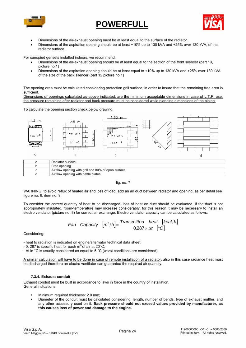
The opening area must be calculated considering protection grill surface, in order to insure that the remaining free area is sufficient. Dimensions of openings calculated as above indicated, are the minimum acceptable dimensions in case of L.T.P. use; the pressure remaining after radiator and back pressure must be considered while planning dimensions of the piping. To calculate the opening section check below drawing.
a Radiator surface b Free opening c Air flow opening with grill and 80% of open surface d Air flow opening with baffle plates
fig. no. 7
WARNING: to avoid reflux of heated air and loss of load, add an air duct between radiator and opening, as per detail see figure no. 6, item no. 9. To consider the correct quantity of heat to be discharged, loss of heat on duct should be evaluated. If the duct is not appropriately insulated, room-temperature may increase considerably, for this reason it may be necessary to install an electro ventilator (picture no. 8) for correct air exchange. Electro ventilator capacity can be calculated as follows:
Ct
hkcalheatdTransmittehmCapacityFan
287,03
Considering: - heat to radiation is indicated on engine/alternator technical data sheet; - 0. 287 is specific heat for each m3 of air at 20°C;
- Δt in °C is usually considered as equal to 5 °C (worst conditions are considered). A similar calculation will have to be done in case of remote installation of a radiator, also in this case radiance heat must be discharged therefore an electro ventilator can guarantee the required air quantity.
7.3.4. Exhaust conduit
Exhaust conduit must be built in accordance to laws in force in the country of installation. General indications:
Minimum required thickness: 2.0 mm; Diameter of the conduit must be calculated considering, length, number of bends, type of exhaust muffler, and
any other accessory used on it. Back pressure should not exceed values provided by manufacturer, as this causes loss of power and damage to the engine.
POWERFULL
Visa S.p.A. Via I° Maggio, 55 – 31043 Fontanelle (TV)
Pagina 25 112000000001-001-01 – 0303/2009Printed in Italy. – All rights reserved.
Exhaust pipes may reach up to 600 °C during operation, therefore it is compulsory to cover pipes with suitable insulation.
Exhaust conduit should be composed of parts, connected by flanges with gaskets, for easy disassembly and
grant maximum tightness. Exhaust conduit should be connected to the engine by a bellow that should absorb the dilatation and separate
the fixed part from the engine. Exhaust conduit should not weigh on the engine manifold.
Engine exhaust gas contains carbon monoxide which is harmful to one’s health and in large quantities can be toxic or cause death.
7.3.5. Engine oil breather pipe
The breather pipe must be connected to the outside in order to avoid leakage of oily fumes that may dirty the engine and radiator. The breather pipe must be connected to a tube of appropriate size that does not carry fumes to the radiator and must have a correct inclination to avoid condensation that may obstruct the pipe.
The area surrounding breather pipe must be protected from possible pollution.
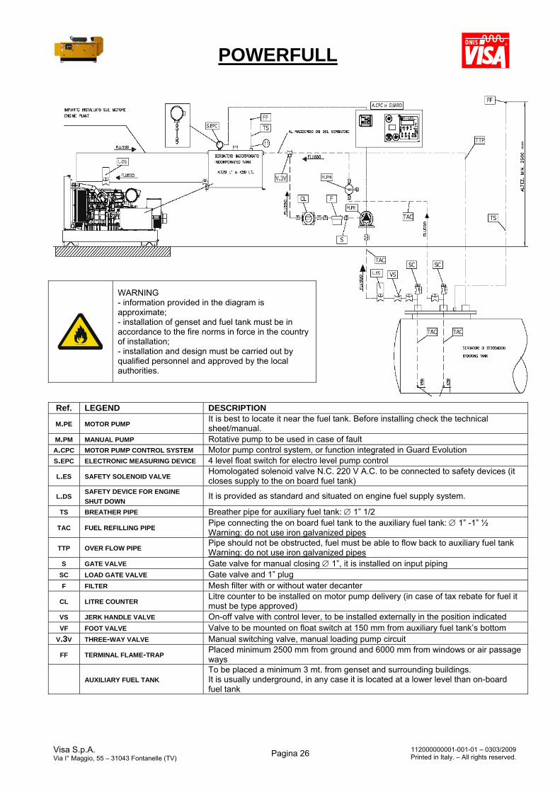
7.3.6. Installation of automatic fuel refilling system
Visa S.p.A. gensets can be provided with an automatic fuel refilling system on request. It can be controlled by the Guard Evolution control panel or by a CPC device. Below is a sample of a basic diagram of an automatic fuel refilling system controlled by the Guard Evolution panel, manufactured by Visa S.p.A.
POWERFULL
Visa S.p.A. Via I° Maggio, 55 – 31043 Fontanelle (TV)
Pagina 26 112000000001-001-01 – 0303/2009Printed in Italy. – All rights reserved.
WARNING - information provided in the diagram is approximate; - installation of genset and fuel tank must be in accordance to the fire norms in force in the country of installation; - installation and design must be carried out by qualified personnel and approved by the local authorities.
Ref. LEGEND DESCRIPTION
M.PE MOTOR PUMP It is best to locate it near the fuel tank. Before installing check the technical sheet/manual.
M.PM MANUAL PUMP Rotative pump to be used in case of fault A.CPC MOTOR PUMP CONTROL SYSTEM Motor pump control system, or function integrated in Guard Evolution S.EPC ELECTRONIC MEASURING DEVICE 4 level float switch for electro level pump control
L.ES SAFETY SOLENOID VALVE Homologated solenoid valve N.C. 220 V A.C. to be connected to safety devices (it closes supply to the on board fuel tank)
L.DS SAFETY DEVICE FOR ENGINE
SHUT DOWN It is provided as standard and situated on engine fuel supply system.
TS BREATHER PIPE Breather pipe for auxiliary fuel tank: 1” 1/2
TAC FUEL REFILLING PIPE Pipe connecting the on board fuel tank to the auxiliary fuel tank: 1” -1” ½ Warning: do not use iron galvanized pipes
TTP OVER FLOW PIPE Pipe should not be obstructed, fuel must be able to flow back to auxiliary fuel tank Warning: do not use iron galvanized pipes
S GATE VALVE Gate valve for manual closing 1”, it is installed on input piping SC LOAD GATE VALVE Gate valve and 1” plug F FILTER Mesh filter with or without water decanter
CL LITRE COUNTER Litre counter to be installed on motor pump delivery (in case of tax rebate for fuel it must be type approved)
VS JERK HANDLE VALVE On-off valve with control lever, to be installed externally in the position indicated VF FOOT VALVE Valve to be mounted on float switch at 150 mm from auxiliary fuel tank’s bottom
V.3V THREE-WAY VALVE Manual switching valve, manual loading pump circuit
FF TERMINAL FLAME-TRAP Placed minimum 2500 mm from ground and 6000 mm from windows or air passage ways
AUXILIARY FUEL TANK To be placed a minimum 3 mt. from genset and surrounding buildings. It is usually underground, in any case it is located at a lower level than on-board fuel tank
POWERFULL
Visa S.p.A. Via I° Maggio, 55 – 31043 Fontanelle (TV)
Pagina 27 112000000001-001-01 – 0303/2009Printed in Italy. – All rights reserved.
8. Electrical connections
8.1. Instructions for electrical connections
Incorrect electrical connections may cause damage to the genset and systems related to it. A qualified electrician should carry out all electrical connections according to the norms in force, and after ensuring that the genset and User system are compatible. BEFORE CARRYING OUT THE CONNECTION, CAREFULLY READ THE LOAD APPLICATION CHAPTER OF THIS MANUAL
It is advised to insert a UPS between the genset and any electronic devices such as a computer, PLC, etc., to avoid that frequency and voltage cause improper functioning during transitory phases (load insertion and disconnecting the load). To protect equipment it is also advised to use a safety device that will cut off the energy supplied by the genset in case voltage values exceed tolerance levels. The electrical connection to the User system is a very important operation: safety and good operation of the genset and User system depend on a correct electrical connection. Before supplying the User system always check:
Electrical diagram relative to the Powerfull genset; Wires connecting the genset to the User system are appropriate for voltage produced and are in accordance to
the norms in force; Wire type, section length and conductivity characteristics have been calculated considering environmental
conditions and norms; User system or distribution panel are provided with the relevant devices to protect these from direct or indirect
contacts and overload; User system and genset are compatible with regards to power, voltage and frequency. Check genset voltage
indicated on label and verify with a tester; Ground is functioning correctly: earth fault relay device works only if this connection is operating; Direction of phases corresponds to User system rotation direction and none of the phases have been connected
to neutral by mistake;
To supply a system that is usually supplied by the Mains, it is necessary to install an ATS with the genset to separate the Mains from the load when the genset is supplying the system and vice-versa. This avoids any possibility of parallel functioning. The installation of the ATS must be carried out by a qualified electrician. Do NOT use a standard genset in parallel with another genset or with the Mains. This use is prohibited and would cause serious damage to the genset.
8.2. Grounding
It is compulsory to connect the Powerfull genset to an appropriate grounding system and check its operation before starting the genset. Such a connection must be carried out based on the distribution system installed and the norms in force. Only qualified personnel should be carry out such operations.
8.2.1. Generating set with earth fault relay device
According to norm IEC364-3, the Powerfull genset’s alternator is connected for a TN system, that is, with supply point directly grounded (in this case neutral). Metallic and exposed electrical parts must be directly grounded. This is Visa S.p.A.’s standard version for gensets with a manual control panel.
8.2.2. Generating set WITHOUT earth fault relay device
According to norm IEC364-3, the Powerfull genset’s alternator is connected for an IT system, that is, with isolated neutral. This is Visa S.p.A.’s standard version for gensets with an automatic control panel for Mains failure.
8.3. Synchronising between genset and Mains or between gensets For this specific requirement the genset must be equipped with the IN-SYNC control panel and necessary devices that allow synchronisation between the genset with the Mains and/or with other gensets. For further information contact Visa S.p.A.’s technical department.
POWERFULL
Visa S.p.A. Via I° Maggio, 55 – 31043 Fontanelle (TV)
Pagina 28 112000000001-001-01 – 0303/2009Printed in Italy. – All rights reserved.
For synchronisation with the Mains, specific agreements and authorisations are required by the utility company together with correct coordination between systems.
9. Start-up instructions
9.1. General start-up principles All Powerfull gensets are tested before leaving Visa S.p.A. For Powerfull genset start-up, a few operations are required which are described in detail in this manual as well as in the engine, alternator and other equipment manuals.
All start-up, maintenance, repair and modification procedures must be carried out according to safety norms and by qualified and trained personnel only. For more information contact Visa S.p.A.’s technical department. Do not start genset without protections or with canopy doors open.
9.2. Necessary checks and operations to be carried out before start-up Before start-up carry out below checks. See also Chapter 11.0
Generating set Visual check to ensure component integrity.
Baseframe Check that bolts vibration-damping pads are securely tightened.
Engine
Visual check of engine parts. Check oil level. Check cooling liquid level. If necessary add liquids to circuits, according to specifications. Check fan belt.
Correct fuel refilling Check that fuel tank and engine supply circuit are not leaking. Carry out de-aeration of circuit.
Battery connection Check that there are no leaks and follow connection diagram.
Alternator Visual check of alternator parts and connections to all terminals.
Electrical panel Check components, instruments, switches, earth fault relay device, protections and accessories.
Never start the engine if there are leaks, damage to parts or protections. If anything unusual is noticed contact Visa S.p.A.’s technical department.
Never approach the genset with heat sources or flames, do not smoke nearby, do not weld or grind while carrying out an inspection. Refill genset only when it is switched off and cooled. If fuel has spilled out of the fuel tank, immediately dry and clean the surface.
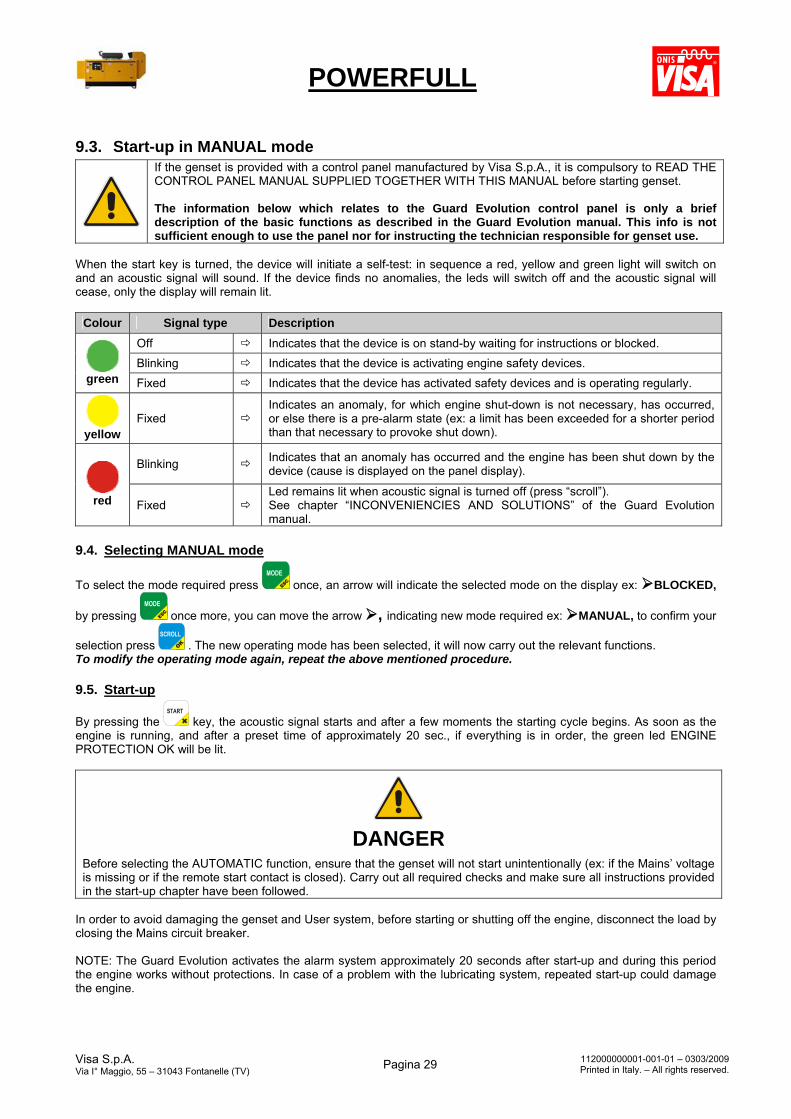
POWERFULL
Visa S.p.A. Via I° Maggio, 55 – 31043 Fontanelle (TV)
Pagina 29 112000000001-001-01 – 0303/2009Printed in Italy. – All rights reserved.
9.3. Start-up in MANUAL mode
If the genset is provided with a control panel manufactured by Visa S.p.A., it is compulsory to READ THE CONTROL PANEL MANUAL SUPPLIED TOGETHER WITH THIS MANUAL before starting genset. The information below which relates to the Guard Evolution control panel is only a brief description of the basic functions as described in the Guard Evolution manual. This info is not sufficient enough to use the panel nor for instructing the technician responsible for genset use.
When the start key is turned, the device will initiate a self-test: in sequence a red, yellow and green light will switch on and an acoustic signal will sound. If the device finds no anomalies, the leds will switch off and the acoustic signal will cease, only the display will remain lit.
Colour Signal type Description
Off Indicates that the device is on stand-by waiting for instructions or blocked.
Blinking Indicates that the device is activating engine safety devices. green Fixed Indicates that the device has activated safety devices and is operating regularly.
yellow
Fixed Indicates an anomaly, for which engine shut-down is not necessary, has occurred, or else there is a pre-alarm state (ex: a limit has been exceeded for a shorter period than that necessary to provoke shut down).
Blinking Indicates that an anomaly has occurred and the engine has been shut down by the device (cause is displayed on the panel display).
red Fixed
Led remains lit when acoustic signal is turned off (press “scroll”). See chapter “INCONVENIENCIES AND SOLUTIONS” of the Guard Evolution manual.
9.4. Selecting MANUAL mode
To select the mode required press once, an arrow will indicate the selected mode on the display ex: BLOCKED,
by pressing once more, you can move the arrow , indicating new mode required ex: MANUAL, to confirm your
selection press . The new operating mode has been selected, it will now carry out the relevant functions. To modify the operating mode again, repeat the above mentioned procedure.
9.5. Start-up
By pressing the key, the acoustic signal starts and after a few moments the starting cycle begins. As soon as the engine is running, and after a preset time of approximately 20 sec., if everything is in order, the green led ENGINE PROTECTION OK will be lit.
DANGER
Before selecting the AUTOMATIC function, ensure that the genset will not start unintentionally (ex: if the Mains’ voltage is missing or if the remote start contact is closed). Carry out all required checks and make sure all instructions provided in the start-up chapter have been followed.
In order to avoid damaging the genset and User system, before starting or shutting off the engine, disconnect the load by closing the Mains circuit breaker. NOTE: The Guard Evolution activates the alarm system approximately 20 seconds after start-up and during this period the engine works without protections. In case of a problem with the lubricating system, repeated start-up could damage the engine.
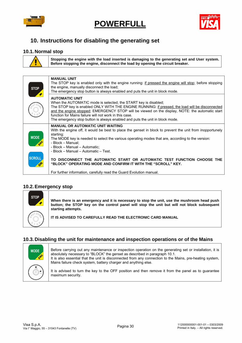
POWERFULL
Visa S.p.A. Via I° Maggio, 55 – 31043 Fontanelle (TV)
Pagina 30 112000000001-001-01 – 0303/2009Printed in Italy. – All rights reserved.
10. Instructions for disabling the generating set
10.1. Normal stop
Stopping the engine with the load inserted is damaging to the generating set and User system. Before stopping the engine, disconnect the load by opening the circuit breaker.
MANUAL UNIT The STOP key is enabled only with the engine running: if pressed the engine will stop; before stopping the engine, manually disconnect the load; The emergency stop button is always enabled and puts the unit in block mode.
AUTOMATIC UNIT When the AUTOMATIC mode is selected, the START key is disabled; The STOP key is enabled ONLY WITH THE ENGINE RUNNING: if pressed, the load will be disconnected and the engine stopped; EMERGENCY STOP will be viewed on the display, NOTE: the automatic start function for Mains failure will not work in this case. The emergency stop button is always enabled and puts the unit in block mode.
MANUAL OR AUTOMATIC UNIT WAITING With the engine off, it would be best to place the genset in block to prevent the unit from inopportunely starting: The MODE key is needed to select the various operating modes that are, according to the version: - Block – Manual; - Block – Manual – Automatic; - Block – Manual – Automatic – Test. TO DISCONNECT THE AUTOMATIC START OR AUTOMATIC TEST FUNCTION CHOOSE THE “BLOCK” OPERATING MODE AND CONFIRM IT WITH THE “SCROLL” KEY. For further information, carefully read the Guard Evolution manual.
10.2. Emergency stop
When there is an emergency and it is necessary to stop the unit, use the mushroom head push button; the STOP key on the control panel will stop the unit but will not block subsequent starting attempts. IT IS ADVISED TO CAREFULLY READ THE ELECTRONIC CARD MANUAL
10.3. Disabling the unit for maintenance and inspection operations or of the Mains
I / ON
0 / OFF
Before carrying out any maintenance or inspection operation on the generating set or installation, it is absolutely necessary to “BLOCK” the genset as described in paragraph 10.1. It is also essential that the unit is disconnected from any connection to the Mains, pre-heating system, Mains failure check system, battery charger and anything else. It is advised to turn the key to the OFF position and then remove it from the panel as to guarantee maximum security.
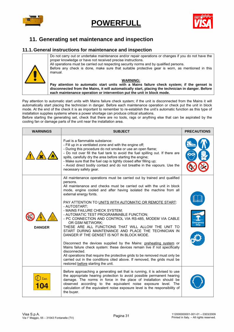
POWERFULL
Visa S.p.A. Via I° Maggio, 55 – 31043 Fontanelle (TV)
Pagina 31 112000000001-001-01 – 0303/2009Printed in Italy. – All rights reserved.
11. Generating set maintenance and inspection
11.1. General instructions for maintenance and inspection
Do not carry out or undertake maintenance and/or repair operations or changes if you do not have the proper knowledge or have not received precise instructions. All operations must be carried out respecting security norms and by qualified persons. Before any check is done, make sure that suitable protective gear is worn, as mentioned in this manual.
WARNING: Pay attention to automatic start units with a Mains failure check system; if the genset is disconnected from the Mains, it will automatically start, placing the technician in danger. Before each maintenance operation or intervention put the unit in block mode.
Pay attention to automatic start units with Mains failure check system; if the unit is disconnected from the Mains it will automatically start placing the technician in danger. Before each maintenance operation or check put the unit in block mode. At the end of the check it is as important to remember to re-establish the unit’s automatic function as this type of installation supplies systems where a power shortage can produce critical situations. Before starting the generating set, check that there are no tools, rags or anything else that can be aspirated by the cooling fan or damage parts of the unit near the installation area.
WARNINGS SUBJECT PRECAUTIONS
Fuel is a flammable substance: - Fill up in a ventilated zone and with the engine off; - During this procedure do not smoke or use an open flame; - Do not over fill the fuel tank to avoid the fuel spilling out. If there are spills, carefully dry the area before starting the engine; - Make sure that the fuel cap is tightly closed after filling up; - Avoid direct bodily contact and do not breathe in the vapours. Use the necessary safety gear.
DANGER
All maintenance operations must be carried out by trained and qualified persons. All maintenance and checks must be carried out with the unit in block mode, engine cooled and after having isolated the machine from all external energy fonts. PAY ATTENTION TO UNITS WITH AUTOMATIC OR REMOTE START: - AUTOSTART; - MAINS FAILURE CHECK SYSTEM; - AUTOMATIC TEST PROGRAMMABLE FUNCTION; - PC CONNECTION AND CONTROL VIA RS-485, MODEM VIA CABLE
OR GSM NETWORK; THESE ARE ALL FUNCTIONS THAT WILL ALLOW THE UNIT TO START DURING MAINTENANCE AND PLACE THE TECHNICIAN IN DANGER IF THE GENSET IS NOT IN BLOCK MODE. Disconnect the devices supplied by the Mains: preheating system or Mains failure check system: these devices remain live if not specifically disconnected. All operations that require the protective grids to be removed must only be carried out in the conditions cited above. If removed, the grids must be restored before starting the unit.
Before approaching a generating set that is running, it is advised to use the appropriate hearing protection to avoid possible permanent hearing damage. The norms in force in the place of installation should be observed according to the equivalent noise exposure level. The calculation of the equivalent noise exposure level is the responsibility of the buyer.
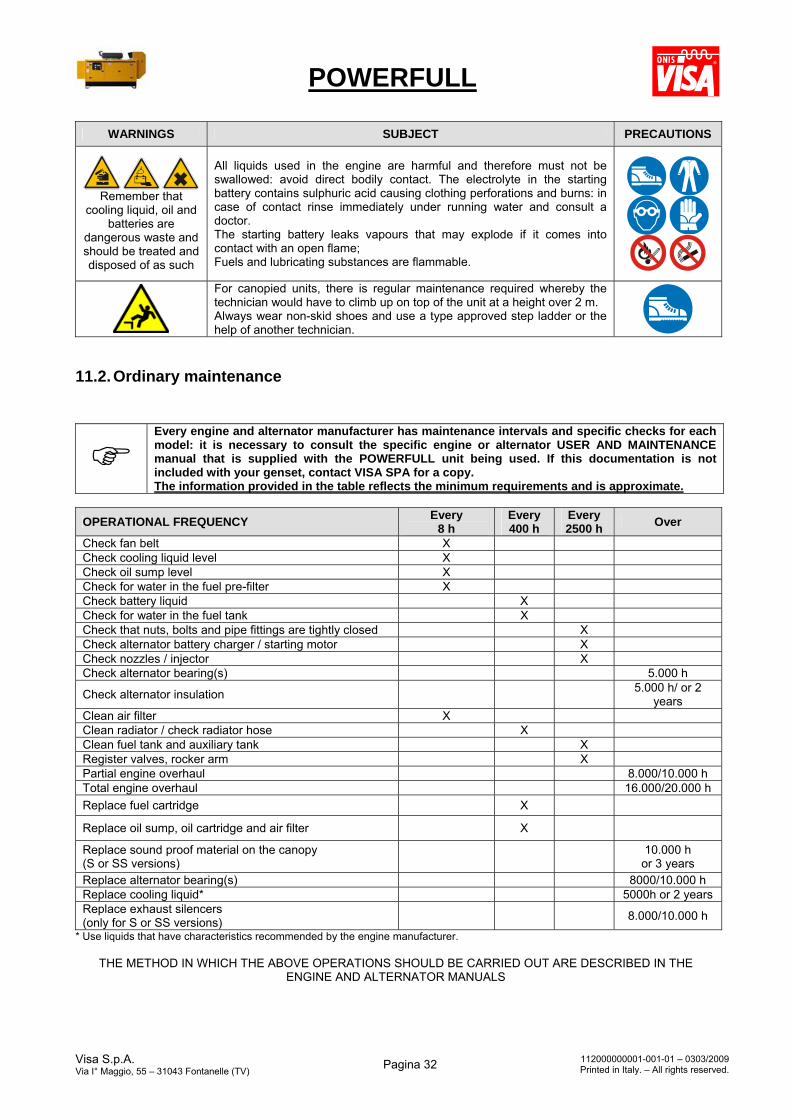
POWERFULL
Visa S.p.A. Via I° Maggio, 55 – 31043 Fontanelle (TV)
Pagina 32 112000000001-001-01 – 0303/2009Printed in Italy. – All rights reserved.
WARNINGS SUBJECT PRECAUTIONS
Remember that
cooling liquid, oil and batteries are
dangerous waste and should be treated and disposed of as such
All liquids used in the engine are harmful and therefore must not be swallowed: avoid direct bodily contact. The electrolyte in the starting battery contains sulphuric acid causing clothing perforations and burns: in case of contact rinse immediately under running water and consult a doctor. The starting battery leaks vapours that may explode if it comes into contact with an open flame; Fuels and lubricating substances are flammable.
For canopied units, there is regular maintenance required whereby the technician would have to climb up on top of the unit at a height over 2 m. Always wear non-skid shoes and use a type approved step ladder or the help of another technician.
11.2. Ordinary maintenance
Every engine and alternator manufacturer has maintenance intervals and specific checks for each model: it is necessary to consult the specific engine or alternator USER AND MAINTENANCE manual that is supplied with the POWERFULL unit being used. If this documentation is not included with your genset, contact VISA SPA for a copy. The information provided in the table reflects the minimum requirements and is approximate.
OPERATIONAL FREQUENCY Every
8 h Every 400 h
Every 2500 h
Over
Check fan belt X Check cooling liquid level X Check oil sump level X Check for water in the fuel pre-filter X Check battery liquid X Check for water in the fuel tank X Check that nuts, bolts and pipe fittings are tightly closed X Check alternator battery charger / starting motor X Check nozzles / injector X Check alternator bearing(s) 5.000 h
Check alternator insulation 5.000 h/ or 2
years Clean air filter X Clean radiator / check radiator hose X Clean fuel tank and auxiliary tank X Register valves, rocker arm X Partial engine overhaul 8.000/10.000 h Total engine overhaul 16.000/20.000 h
Replace fuel cartridge X
Replace oil sump, oil cartridge and air filter X
Replace sound proof material on the canopy (S or SS versions)
10.000 h or 3 years
Replace alternator bearing(s) 8000/10.000 h Replace cooling liquid* 5000h or 2 years Replace exhaust silencers (only for S or SS versions)
8.000/10.000 h
* Use liquids that have characteristics recommended by the engine manufacturer.
THE METHOD IN WHICH THE ABOVE OPERATIONS SHOULD BE CARRIED OUT ARE DESCRIBED IN THE ENGINE AND ALTERNATOR MANUALS
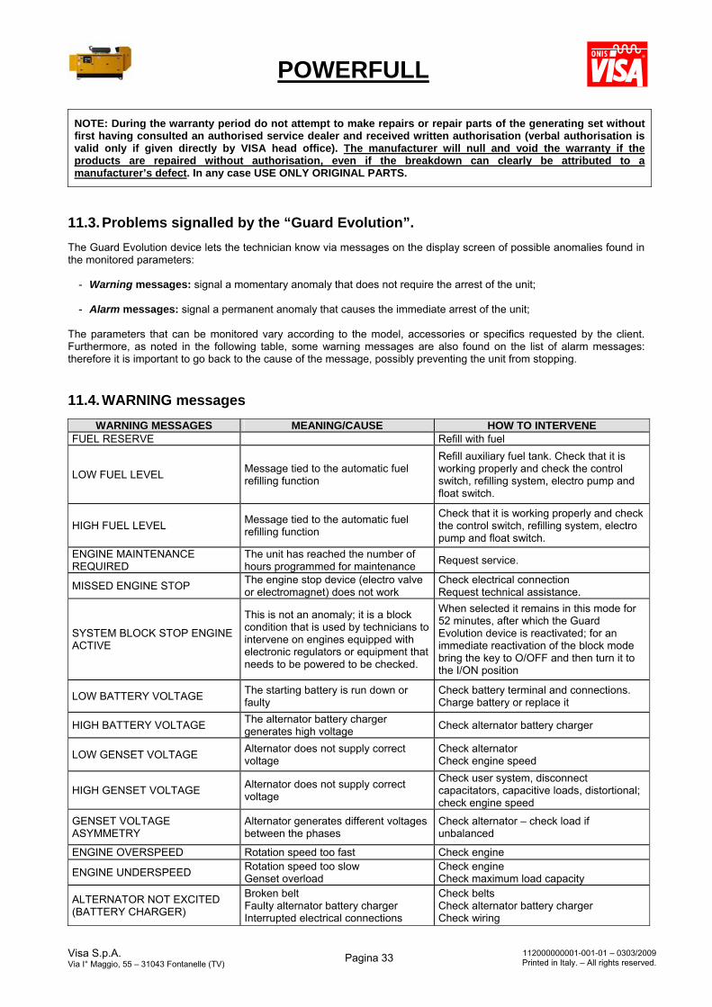
POWERFULL
Visa S.p.A. Via I° Maggio, 55 – 31043 Fontanelle (TV)
Pagina 33 112000000001-001-01 – 0303/2009Printed in Italy. – All rights reserved.
NOTE: During the warranty period do not attempt to make repairs or repair parts of the generating set without first having consulted an authorised service dealer and received written authorisation (verbal authorisation is valid only if given directly by VISA head office). The manufacturer will null and void the warranty if the products are repaired without authorisation, even if the breakdown can clearly be attributed to a manufacturer’s defect. In any case USE ONLY ORIGINAL PARTS.
11.3. Problems signalled by the “Guard Evolution”.
The Guard Evolution device lets the technician know via messages on the display screen of possible anomalies found in the monitored parameters:
- Warning messages: signal a momentary anomaly that does not require the arrest of the unit; - Alarm messages: signal a permanent anomaly that causes the immediate arrest of the unit;
The parameters that can be monitored vary according to the model, accessories or specifics requested by the client. Furthermore, as noted in the following table, some warning messages are also found on the list of alarm messages: therefore it is important to go back to the cause of the message, possibly preventing the unit from stopping.
11.4. WARNING messages
WARNING MESSAGES MEANING/CAUSE HOW TO INTERVENE FUEL RESERVE Refill with fuel
LOW FUEL LEVEL Message tied to the automatic fuel refilling function
Refill auxiliary fuel tank. Check that it is working properly and check the control switch, refilling system, electro pump and float switch.
HIGH FUEL LEVEL Message tied to the automatic fuel refilling function
Check that it is working properly and check the control switch, refilling system, electro pump and float switch.
ENGINE MAINTENANCE REQUIRED
The unit has reached the number of hours programmed for maintenance
Request service.
MISSED ENGINE STOP The engine stop device (electro valve or electromagnet) does not work
Check electrical connection Request technical assistance.
SYSTEM BLOCK STOP ENGINE ACTIVE
This is not an anomaly; it is a block condition that is used by technicians to intervene on engines equipped with electronic regulators or equipment that needs to be powered to be checked.
When selected it remains in this mode for 52 minutes, after which the Guard Evolution device is reactivated; for an immediate reactivation of the block mode bring the key to O/OFF and then turn it to the I/ON position
LOW BATTERY VOLTAGE The starting battery is run down or faulty
Check battery terminal and connections. Charge battery or replace it
HIGH BATTERY VOLTAGE The alternator battery charger generates high voltage
Check alternator battery charger
LOW GENSET VOLTAGE Alternator does not supply correct voltage
Check alternator Check engine speed
HIGH GENSET VOLTAGE Alternator does not supply correct voltage
Check user system, disconnect capacitators, capacitive loads, distortional; check engine speed
GENSET VOLTAGE ASYMMETRY
Alternator generates different voltages between the phases
Check alternator – check load if unbalanced
ENGINE OVERSPEED Rotation speed too fast Check engine
ENGINE UNDERSPEED Rotation speed too slow Genset overload
Check engine Check maximum load capacity
ALTERNATOR NOT EXCITED (BATTERY CHARGER)
Broken belt Faulty alternator battery charger Interrupted electrical connections
Check belts Check alternator battery charger Check wiring
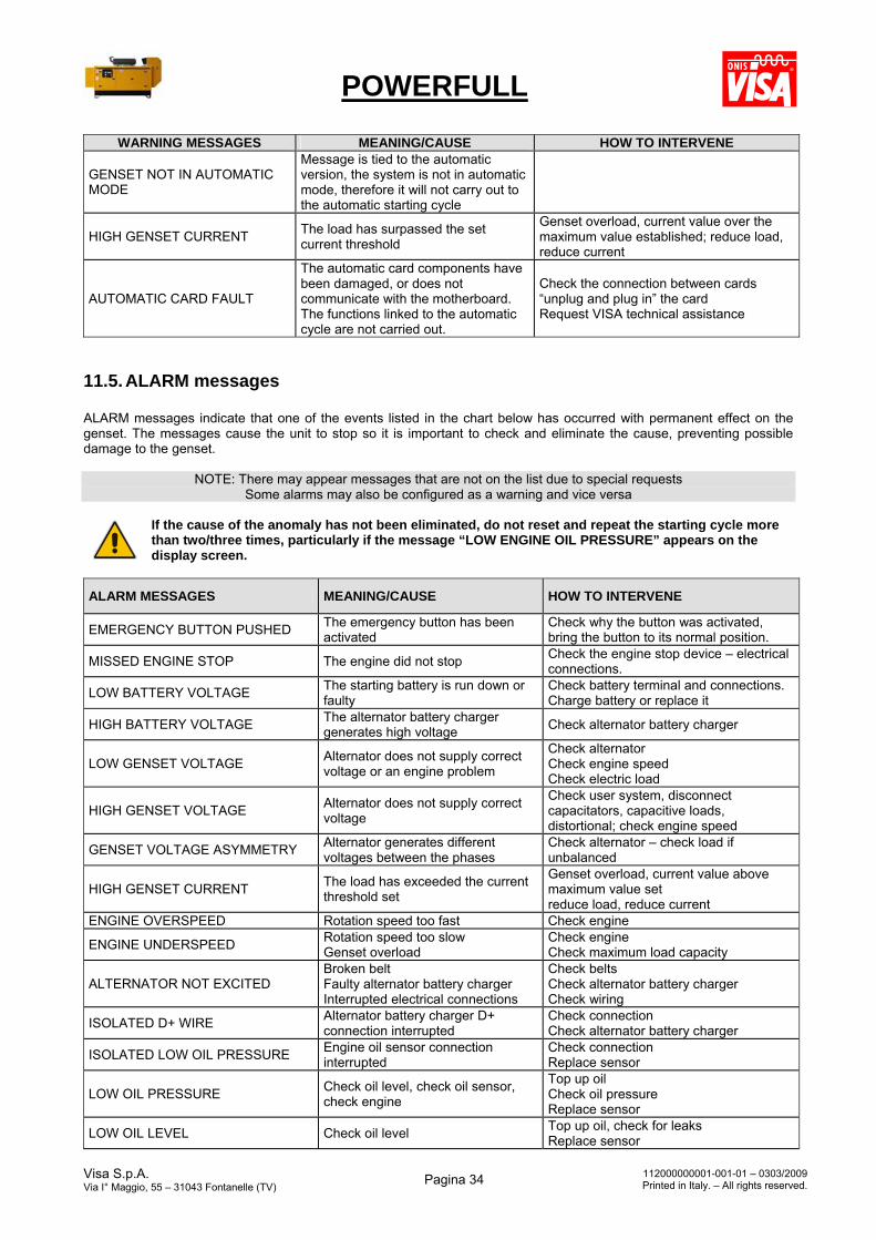
POWERFULL
Visa S.p.A. Via I° Maggio, 55 – 31043 Fontanelle (TV)
Pagina 34 112000000001-001-01 – 0303/2009Printed in Italy. – All rights reserved.
WARNING MESSAGES MEANING/CAUSE HOW TO INTERVENE
GENSET NOT IN AUTOMATIC MODE
Message is tied to the automatic version, the system is not in automatic mode, therefore it will not carry out to the automatic starting cycle
HIGH GENSET CURRENT The load has surpassed the set current threshold
Genset overload, current value over the maximum value established; reduce load, reduce current
AUTOMATIC CARD FAULT
The automatic card components have been damaged, or does not communicate with the motherboard. The functions linked to the automatic cycle are not carried out.
Check the connection between cards “unplug and plug in” the card Request VISA technical assistance
11.5. ALARM messages ALARM messages indicate that one of the events listed in the chart below has occurred with permanent effect on the genset. The messages cause the unit to stop so it is important to check and eliminate the cause, preventing possible damage to the genset.
NOTE: There may appear messages that are not on the list due to special requests Some alarms may also be configured as a warning and vice versa
If the cause of the anomaly has not been eliminated, do not reset and repeat the starting cycle more than two/three times, particularly if the message “LOW ENGINE OIL PRESSURE” appears on the display screen.
ALARM MESSAGES MEANING/CAUSE HOW TO INTERVENE
EMERGENCY BUTTON PUSHED The emergency button has been activated
Check why the button was activated, bring the button to its normal position.
MISSED ENGINE STOP The engine did not stop Check the engine stop device – electrical connections.
LOW BATTERY VOLTAGE The starting battery is run down or faulty
Check battery terminal and connections. Charge battery or replace it
HIGH BATTERY VOLTAGE The alternator battery charger generates high voltage
Check alternator battery charger
LOW GENSET VOLTAGE Alternator does not supply correct voltage or an engine problem
Check alternator Check engine speed Check electric load
HIGH GENSET VOLTAGE Alternator does not supply correct voltage
Check user system, disconnect capacitators, capacitive loads, distortional; check engine speed
GENSET VOLTAGE ASYMMETRY Alternator generates different voltages between the phases
Check alternator – check load if unbalanced
HIGH GENSET CURRENT The load has exceeded the current threshold set
Genset overload, current value above maximum value set reduce load, reduce current
ENGINE OVERSPEED Rotation speed too fast Check engine
ENGINE UNDERSPEED Rotation speed too slow Genset overload
Check engine Check maximum load capacity
ALTERNATOR NOT EXCITED Broken belt Faulty alternator battery charger Interrupted electrical connections
Check belts Check alternator battery charger Check wiring
ISOLATED D+ WIRE Alternator battery charger D+ connection interrupted
Check connection Check alternator battery charger
ISOLATED LOW OIL PRESSURE Engine oil sensor connection interrupted
Check connection Replace sensor
LOW OIL PRESSURE Check oil level, check oil sensor, check engine
Top up oil Check oil pressure Replace sensor
LOW OIL LEVEL Check oil level Top up oil, check for leaks Replace sensor
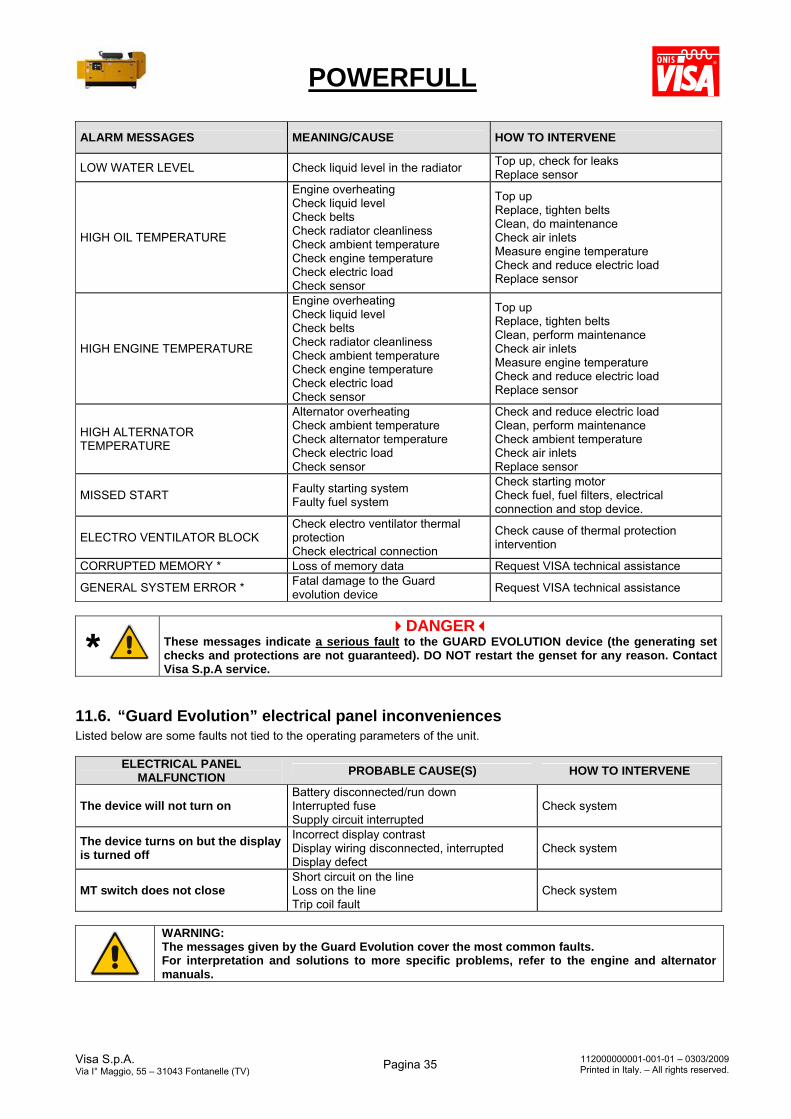
POWERFULL
Visa S.p.A. Via I° Maggio, 55 – 31043 Fontanelle (TV)
Pagina 35 112000000001-001-01 – 0303/2009Printed in Italy. – All rights reserved.
ALARM MESSAGES MEANING/CAUSE HOW TO INTERVENE
LOW WATER LEVEL Check liquid level in the radiator Top up, check for leaks Replace sensor
HIGH OIL TEMPERATURE
Engine overheating Check liquid level Check belts Check radiator cleanliness Check ambient temperature Check engine temperature Check electric load Check sensor
Top up Replace, tighten belts Clean, do maintenance Check air inlets Measure engine temperature Check and reduce electric load Replace sensor
HIGH ENGINE TEMPERATURE
Engine overheating Check liquid level Check belts Check radiator cleanliness Check ambient temperature Check engine temperature Check electric load Check sensor
Top up Replace, tighten belts Clean, perform maintenance Check air inlets Measure engine temperature Check and reduce electric load Replace sensor
HIGH ALTERNATOR TEMPERATURE
Alternator overheating Check ambient temperature Check alternator temperature Check electric load Check sensor
Check and reduce electric load Clean, perform maintenance Check ambient temperature Check air inlets Replace sensor
MISSED START Faulty starting system Faulty fuel system
Check starting motor Check fuel, fuel filters, electrical connection and stop device.
ELECTRO VENTILATOR BLOCK Check electro ventilator thermal protection Check electrical connection
Check cause of thermal protection intervention
CORRUPTED MEMORY * Loss of memory data Request VISA technical assistance
GENERAL SYSTEM ERROR * Fatal damage to the Guard evolution device
Request VISA technical assistance
* DANGER
These messages indicate a serious fault to the GUARD EVOLUTION device (the generating set checks and protections are not guaranteed). DO NOT restart the genset for any reason. Contact Visa S.p.A service.
11.6. “Guard Evolution” electrical panel inconveniences Listed below are some faults not tied to the operating parameters of the unit.
ELECTRICAL PANEL MALFUNCTION
PROBABLE CAUSE(S) HOW TO INTERVENE
The device will not turn on Battery disconnected/run down Interrupted fuse Supply circuit interrupted
Check system
The device turns on but the display is turned off
Incorrect display contrast Display wiring disconnected, interrupted Display defect
Check system
MT switch does not close Short circuit on the line Loss on the line Trip coil fault
Check system
WARNING: The messages given by the Guard Evolution cover the most common faults. For interpretation and solutions to more specific problems, refer to the engine and alternator manuals.
POWERFULL
Visa S.p.A. Via I° Maggio, 55 – 31043 Fontanelle (TV)
Pagina 36 112000000001-001-01 – 0303/2009Printed in Italy. – All rights reserved.
11.7. How to request assistance To reduce the service call times of Visa’s Assistance, we kindly ask that the following information be provided to facilitate a solution to the problem:
Try to identify the cause of the problem by checking the above table; Contact an authorized Visa dealer making sure you have the following information available:
1) Details indicated on the label attached to the genset; 2) Purchase invoice details; 3) Name of the company that bought the genset; 4) Name of the reseller (only in case of direct contact with Visa) 5) A description of the fault with as much detail as possible on the probable cause, any incorrect handling
and/or inappropriate use; 6) The message shown on the lower line of Guard Evolution display.
We remind you that warranty validity limitations are indicated in paragraph 4 of the sales conditions provided by Visa S.p.A. when purchasing the unit. In particular it is no longer valid in case of improper use or overload, incorrect or missed maintenance, modifications or replacements of parts with components not approved by Visa S.p.A. or by the manufacturers of the same.
12. Storage instructions Listed below are the instructions for procedures to be carried out on components before storage to avoid deterioration:
12.1. Engine Remove liquids from the engine: oil, fuel and antifreeze Spray anticorrosive oil on the engine’s internal parts Fill the engine with anticorrosive oil and injection circuit with anticorrosive fuel Fill the cooling circuit with antifreeze and passivated liquid Loosen the fan belts Spray all electrical contacts with a specific protective liquid Lubricate all joints and levers with graphitized grease Spray a layer of anticorrosive oil on external engine parts Apply a notice advising “DO NOT START ENGINE”
12.2. Alternator Clean internal parts by using compressed air Check bearings and greasing
12.3. Battery Remove the starting battery and charge it at 1,270 specified density Protect terminals with appropriate grease
12.4. Electrical parts Clean the parts Spray appropriate protective liquid
Note: only the use of products and additives authorized by the engine manufacturer is permitted. After carrying out the above procedures, place the genset in a covered, dry and cool location.
13. Instructions for decommissioning When decommissioning, all genset components are to be considered, and disposed of, as special waste. In particular, the battery(ies) and engine liquids are dangerous waste. It is strongly recommended to adhere to all norms in force when decommissioning. The laws in force in the country of destination must be followed when getting rid of equipment at the conclusion of its use or in case of demolition. All genset identification labels and relative documents must be destroyed.
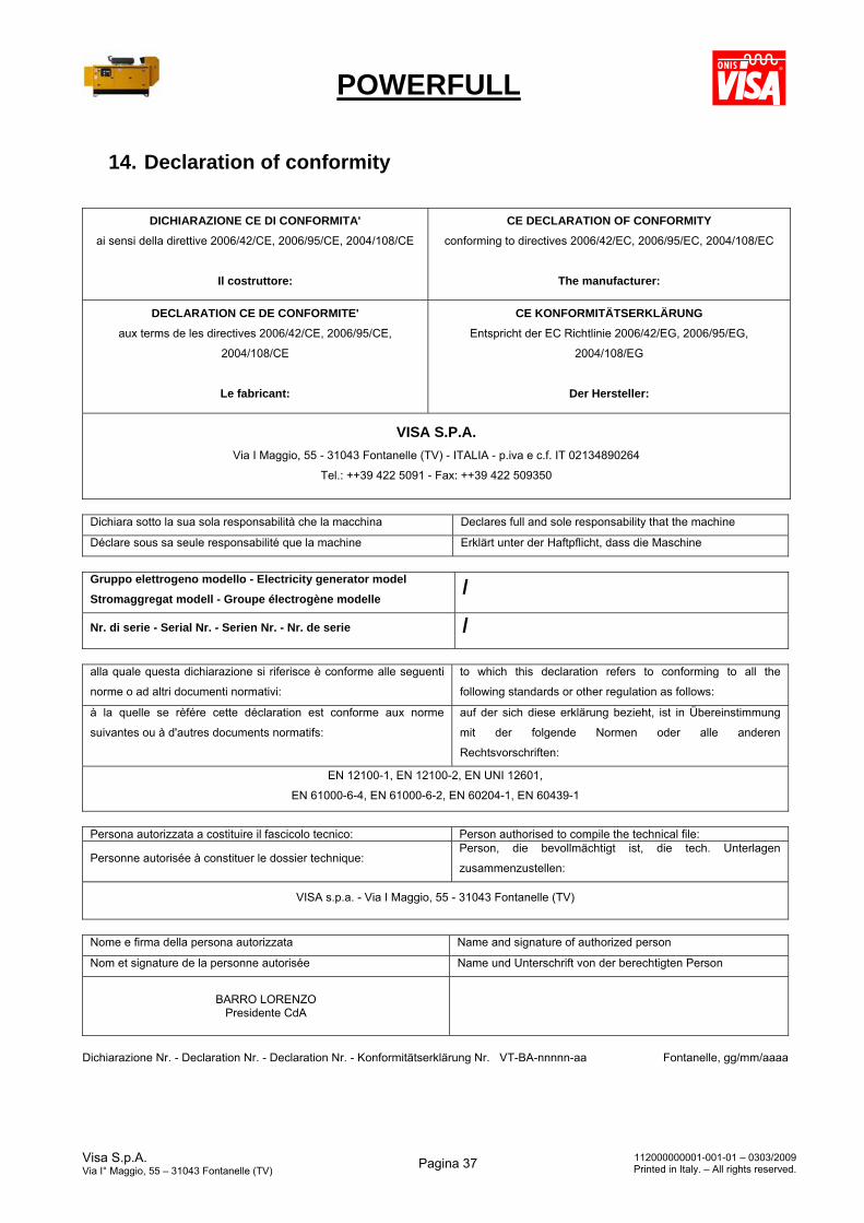
POWERFULL
Visa S.p.A. Via I° Maggio, 55 – 31043 Fontanelle (TV)
Pagina 37 112000000001-001-01 – 0303/2009Printed in Italy. – All rights reserved.
14. Declaration of conformity
DICHIARAZIONE CE DI CONFORMITA'
ai sensi della direttive 2006/42/CE, 2006/95/CE, 2004/108/CE
Il costruttore:
CE DECLARATION OF CONFORMITY
conforming to directives 2006/42/EC, 2006/95/EC, 2004/108/EC
The manufacturer:
DECLARATION CE DE CONFORMITE'
aux terms de les directives 2006/42/CE, 2006/95/CE,
2004/108/CE
Le fabricant:
CE KONFORMITÄTSERKLÄRUNG
Entspricht der EC Richtlinie 2006/42/EG, 2006/95/EG,
2004/108/EG
Der Hersteller:
VISA S.P.A.
Via I Maggio, 55 - 31043 Fontanelle (TV) - ITALIA - p.iva e c.f. IT 02134890264
Tel.: ++39 422 5091 - Fax: ++39 422 509350
Dichiara sotto la sua sola responsabilità che la macchina Declares full and sole responsability that the machine
Déclare sous sa seule responsabilité que la machine Erklärt unter der Haftpflicht, dass die Maschine
Gruppo elettrogeno modello - Electricity generator model
Stromaggregat modell - Groupe électrogène modelle /
Nr. di serie - Serial Nr. - Serien Nr. - Nr. de serie /
alla quale questa dichiarazione si riferisce è conforme alle seguenti
norme o ad altri documenti normativi:
to which this declaration refers to conforming to all the
following standards or other regulation as follows:
à la quelle se rèfére cette déclaration est conforme aux norme
suivantes ou à d'autres documents normatifs:
auf der sich diese erklärung bezieht, ist in Übereinstimmung
mit der folgende Normen oder alle anderen
Rechtsvorschriften:
EN 12100-1, EN 12100-2, EN UNI 12601,
EN 61000-6-4, EN 61000-6-2, EN 60204-1, EN 60439-1
Persona autorizzata a costituire il fascicolo tecnico: Person authorised to compile the technical file:
Personne autorisée à constituer le dossier technique: Person, die bevollmächtigt ist, die tech. Unterlagen
zusammenzustellen:
VISA s.p.a. - Via I Maggio, 55 - 31043 Fontanelle (TV)
Nome e firma della persona autorizzata Name and signature of authorized person
Nom et signature de la personne autorisée Name und Unterschrift von der berechtigten Person
BARRO LORENZO Presidente CdA
Dichiarazione Nr. - Declaration Nr. - Declaration Nr. - Konformitätserklärung Nr. VT-BA-nnnnn-aa Fontanelle, gg/mm/aaaa
Recommended