Int. J. Communications, Network and System Sciences, 2017, 10, 35-47 http://www.scirp.org/journal/ijcns
ISSN Online: 1913-3723 ISSN Print: 1913-3715
DOI: 10.4236/ijcns.2017.108B005 August 14, 2017
Power Allocation Optimization for Spectrum-Efficient Multi-Pair Two-Way Massive MIMO Full-Duplex Relay over Ricean Channels
Chuangyou Wu, Tong Yue, Kui Xu, Wei Xie
PLA University of Science and Technology, Nanjing, China
Abstract In this paper we investigate the power allocation optimization for spectrum efficient multi-pair two-way massive MIMO (TWMM) amplify-and-forward (AF) full-duplex (FD) relay over Ricean fading channels, where multiple us-er-pairs exchange information within pair through a AF-FD relay with very large number of antennas, while each user equipped with a single antenna. First, the zero-forcing reception/zeroforcing transmission and maxi-mum-ratio combining/maximum ratio transmission processing matrices with imperfect channel state information at the relay are presented. Then, the uni-fied asymptotic signal-to-interference-plus-noise ratio (SINR) expression of the system at general power scaling schemes are investigates. Finally, the joint user-relay power allocation (JURPA) scheme is proposed to improve the spectral efficiency of TWMM-AF-FD relay system. Simulation results show that the proposed JURPA scheme outperforms traditional user-side only power allocation scheme.
Keywords Massive MIMO, Ricean Fading Channels , Processing Matrices, Power Allocation
1. Introduction
The ever growing challenges for significant traffic growth driven by mobile In-ternet and Internet of things have made system capacity enhancement one of the most important features in next generation wireless communication systems. The general consensus is that the aggregate data rate will increase by roughly
How to cite this paper: Wu, C.Y., Yue, T., Xu, K. and Xie, W. (2017) Power Allocation Optimization for Spectrum-Efficient Multi- Pair Two-Way Massive MIMO Full-Duplex Relay over Ricean Channels. Int. J. Commu-nications, Network and System Sciences, 10, 35-47. https://doi.org/10.4236/ijcns.2017.108B005 Received: March 20, 2017 Accepted: August 11, 2017 Published: August 14, 2017
C. Y. Wu et al.
36
1000X by 2020. Massive multiple-input multiple output (MIMO) [1] is identified as one of the key enabling technologies to achieve this goal due to its strong po-tential in boosting the spectral efficiency (SE) of wireless networks [1] [2].
The term massive MIMO indicates that the base station (BS) or relay employs a number of antennas much larger than the number of active data streams per time-frequency resource. Massive MIMO was originally designed for time divi-sion duplex (TDD) system [1]-[7], since by exploiting the channel reciprocity in TDD setting, the required channel state information (CSI) for downlink trans-mission at the BS can be easily obtained via uplink training [1]. The training overhead scales linearly with the number of user equipments (UEs) and is inde-pendent with the number of BS antennas. As frequency division duplex (FDD) dominates the current wireless cellular systems, the application of massive MIMO in FDD system is even more desirable. In FDD massive MIMO, the downlink training and corresponding CSI feedback yield an unacceptably high overhead. One attempt of practical FDD massive MIMO is called joint spatial division and multiplexing (JSDM) [8], where the correlation between channels is exploited to reduce the training and feedback dimensions. Another scheme is called beam divi-sion multiple access (BDMA) [9], which gets rid of the need of CSI at transmitter and provides strong potential to realize massive MIMO gain in FDD system.
In TDD and FDD massive MIMO systems (namely halfduplex (HD) massive MIMO systems), the uplink and downlink UEs must be allocated with ortho-gonal time slots or frequency bands, which results in insufficient utilization of time-frequency resources. Inspired by the recent development of full-duplex (FD) communication [10], co-time co-frequency uplink and downlink (CCUD) trans- mission becomes another option in the cellular system. Although attractive in SE, CCUD transmission is considered challenging due to the strong self interference (SI) caused by the signal leakage between BS/relay transmitter and receiver, es-pecially when the BS is equipped with large-scale antenna arrays. To support the CCUD transmission, the BS employs a separate antenna configuration where two separate large-scale antenna arrays are used for transmission and reception, respectively [11]. In this case, the downlink channel reciprocity is commonly considered as unavailable [12]. Without reciprocity, the training overhead to obtain the downlink CSI scales linearly with the number of BS antennas, which poses another big challenge.
Note that the CCUD transmission in the cellular system with massive MIMO BS/relay has been investigated recently in several works (See [13] [14] [15] and the references therein). The authors in [13] studied the SE performance of CCUD transmission in both macro-cell and small-cell environments. The linear beamforming design of the BS for CCUD transmission has been considered in [14]. The power allocation scheme for user-side only has considered in [15] to optimize the system spectral efficiency.
In this paper, we investigate the power allocation optimization for spectrum efficient multi-pair two-way massive MIMO (TWMM) amplify-and-forward (AF) FD relay over Ricean fading channels. The unified asymptotic signal-to-
C. Y. Wu et al.
37
interferenceplus-noise ratio (SINR) expression of the system based on the be- amforming matrixes of MRC/MRT and ZFR/ZFT at the relay, at the pow-er-scaling ( , , , ,/ , /a b
s k s k R k R kP E M P E M= = , 0 , 1a b≤ ≤ ,s kE and ,R kE are fixed) are investigates. Moreover, the joint user-relay power allocation scheme is pro-posed to improve the spectral efficiency of TWMM-AF-FD relay system.
Notation: TX ; HX ; *X ; 1X − ; ( )Tr X to denote the transpose, conju-gate-transpose, conjugate, inverse and the trace of X . respectively. MI de-notes an M M× identity matrix. · is the expectation operator, · repre- sents the Euclidean norm.
2. System Model
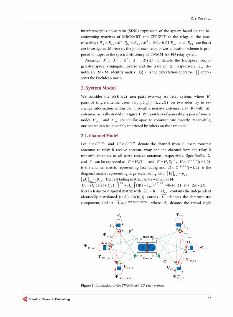
We consider the ( )2K K ≥ user-pairs two-way AF relay system, where K pairs of single-antenna users 2 1 21 1, , ),lU U l K− = …)( ( on two sides try to ex-change information within pair through a massive antenna relay (R) with M antennas, as is illustrated in Figure 1. Without loss of generality, a pair of source nodes 2 1lU − and 21U are too far apart to communicate directly. Meanwhile, one source can be inevitably interfered by others on the same side.
2.1. Channel Model
Let 2M KG C ×∈ and 2T K MF C ×∈ denote the channel from all users transmit antennas to relay R receive antenna array and the channel from the relay R transmit antennas to all users receive antennas, respectively. Specifically, G and F can be expressed as 1/2
1 1G H D= and 1/22 2F H D= , 2 ( 1, 2)M K
iH C i×∈ = is the channel matrix representing fast fading and 2 2 ( 1, 2)K K
iD iC × =∈ is the diagonal matrix representing large-scale fading with [ ]1 ,g kKKD β= , [ ]2 ,f kKKD β= . The fast fading matrix can be written as [4],
1/2 1/21 12 , 2( ) ( )i i K i w KH H I H I
− −− − = Ω Ω+ + Ω Ω+ , where Ω is a 2 2K K× Ricean K-factor diagonal matrix with ii iKΩ = . ,i wH contains the independent identically distributed (i.i.d.) (0,1)CN entries. iH denotes the deterministic component, and let ( 1)(2 / )sin kj m
iH e π λ θ− −= , where kθ denotes the arrival angle
Figure 1. Illustration of the TWMM-AF-FD relay system.
C. Y. Wu et al.
38
of the k-th user, λ is the wavelength, and d is the antenna spacing. For con-venience, we set / 2d λ= .
Let M MRRG C ×∈ denote the echo interference (EI) channel matrix between
the relay transmit and receive arrays with (i.i.d.) 2(0, )rrCN σ elements. ,k kΨ and ,k iΨ represent the self-loop interference coefficient at kU and the in-ter-user interference channel coefficient from iU to kU . 1,3, , 2 1kS K= − or 2,4, , 2 K denotes the set of users on the same side. ,k kΨ and ,k iΨ can be modeled as i.i.d ,(0, )k kCN Φ and ,(0, )k iCN Φ random variables.
2.2. Channel Estimation and Data Transmission
Since it is impossible for the relay to obtain the complete channel state informa-tion from all the channels, so it is necessary to estimate the channel matrix. For the Ricean fading channel model, the Ricean K factor matrix and the LOS transmission signal component are fully known in the relay and the user. So we only need to estimate 1/2
1, 1w wG H D= and 1/22, 2w wF H D= , since wG and wF
are i.i.d, we can use minimum mean square error (MMSE) estimator. Let T be the length of the coherence interval and let be τ the number of symbols used for uplink pilots. In the training part of the coherent interval, all users receive and transmit antennas simultaneously send symbols of length τ to the relay.
The received pilots matrices at the R’s receive and transmit antenna arrays are given by 1 2
ˆr T T rY P G P F Nτ τ= Φ + Φ + and 1 2
ˆt T T tY P G P F Nτ τ= Φ + Φ + ,
among them 2 ( 1, 2)Ki C iτ×Φ ∈ = . are pilot sequences transmitted from all users
transmit antennas and all users receive antennas, respectively. 2M KF C ×∈ is the channel matrices from all users transmit antennas to R’s transmit antenna array and 2M KF C ×∈ is from all users receive antennas to R’s receive antenna array.
rN and tN are additive white Gaussian noise (AWGN) matrices with (i.i.d.) (0, )CN σ elements. And TP is the transmit power of each pilot symbol. All
pilot sequences are assumed to be paired and distributed independently,
2
H
i i KIΦ Φ = and 2
H
i J KOΦ Φ = ( i j≠ ) where1/21
2( )i K iI − Φ Ω + Φ . This requires 4Kτ = . and we set 4Kτ = in this paper. We consider the LOS com-ponent assumed to be known and can be removed, the remaining terms of the received matrices are
, 1 2r w T w T w rY P G P F Nτ τ= Φ + Φ + , and
, 1 2t w T w T w tY P G P F Nτ τ= Φ + Φ + . The MMSE estimate of wG and wF are
1 1, 1 2 1(1 ) ( (1 ) )
HW T r w K TG P Y I P Dτ τ − −= Φ + and
1 1, 2 2 2(1 ) ( (1 ) )
HW T t w K TF P Y I P Dτ τ − −= Φ + . According to MMSE estimates, the actual channel can be expressed as G G G= + and F F F= + , G ( F ) and G ( F ) denote the available
channel estimate and estimation error, respectively. The elements of the i-th column of G and F are RVs with zero means and variances
2, , ,( )( 1)g i g i p g i iP Kε β σ σ β= + + and 2
, , ,( )( 1)f i f i p f i iP Kε β σ σ β= + + where
p TP Pτ= . In addition, due to the nature of MMSE estimates, G is indepen-dent of G and F is independent of F .
At time instant t, all sources transmit their symbols to R and R forwards the

C. Y. Wu et al.
39
amplified signal to destinations. The received signals at the relay and the k’th user are given by:
( ) ( ) ( ) ( )R RR R Ry t Gx t G x t n t= + + . (1)
,( ) ( ) ( ) ( )k
Tk k R k i i k
i Sy t f x t x t n tψ
∈
= + +∑ . (2)
where [ ]1 2 2( ) ( ), ( ) ( ) TKx t x t x t x t= and ,1 ,2( ) ( ) diag(H
S S Kx t x t P P= = ∧, , ) ,( )Rx t denotes the transmit vector of R. n ( )R t and n ( )K t represent the noise
vector at R and kU . the elements of n ( )R t and n ( )K t are assumed to be (i.i.d.) (0, )nCN σ and (0, )nCN σ .
The transmit vector of R at time instant t can be expressed as: ( ) ( )R Rx t Wy t d= − (3)
where M MW C ×∈ is the beamforming matrix, and d denotes the processing delay at R. In this paper, some loop interference cancellation methods [16] can be adopted at the relay before carrying out (3), so we can regard the residual loop interference at R as additional noise. So, we replace ( )Rx t in the loop in-terference term in (1) by a Gaussian noise source ( )Rx t with the same power limitation to represent the residual loop interference signal. Then (2) can be ex-pressed as:
,
ˆ ˆ ˆ( ) ( ) [( ) ( ) ( )( )] ( ) ( )
k
T Tk k k RR R
R k i i ki S
y t f f W G G x t d G x t dn t d x t n tψ
∈
= + ∆ + ∆ − + −
+ − + +∑
(4)
3. Beamforming Design and SINR Anlysis
In this section, we introduce the ZFR/ZFT-based and MRC/MRT-based beam-forming design, the end-to-end SINR of the proposed transceiver schemes for multi-pair two-way MM-AFFDR system are analyzed.
Lemma 1: By the law of large numbers, if M is large enough, the inner product of any two columns in the estimate channel matrix G can be expressed as [17]:
, ,,. .
,
( ) ,ˆ ˆ1
0,
g n p g nHn g na sn i
n p g nM
PK i ng g K P
Mi n
β βη
σ β→∞
+ = = + +→
≠
(5)
and
, ,,. .
,
ˆ ˆ ( ) ,1
0,
f n p f nHn f na sn i
n p f nM
PK i nf f K P
Mi n
β βη
σ β→∞
+ = = + +→
≠
(6)
According to Lemma 1, it can be easily obtained that:
. .,1 ,2 ,2 1
ˆ ˆ , ,
Ha s
g g g kM
G G diag QM
η η η→∞→ = (7)
and
. .,1 ,2 ,2 2
ˆ ˆ , ,
Ha s
f f f kM
F F diag QM
η η η→∞→ = (8)

C. Y. Wu et al.
40
3.1. ZFR/ZFT Beamforming
The ZFR/ZFT beamforming matrix can be expressed as [18]:
* * 1 1( ) ( )T H H
zf zfW a F F F P G G G− −= (9)
where 1P diag( )KP P= , , , 0 1
P , 1, ,1 0l l K
= =
. zfa is the amplification
factor, which can be expressed as:
' '
,. .2 2 2
1 2 2 1 1, , , , . ,2, ,
1 1 1
1 1 ( )
R ka szf M k k k
s i f i rr R k s j g j f if i g ii j i
Pa
P P PM M
η η σ σ ε η η→∞
− − −
= = =
→+ + +∑ ∑ ∑
(10)
where ’( , )i i is a pair of user.
Theorem 1: Using ZFR/ZFT beamforming matrix with imperfect CSI from MMSE estimation, the end-to-end SINR at the k’th user can be expressed asym- ptotically (in M) as:
'
2,
22 2 1
, ,,k
s k zfk
zfee eik k s i k i ng k
i S
P aa
y y PM
γση σ−
=
= + + + Φ + ∑
(11)
the power for channel estimation error 2ee
ky
and power for echo interfe-rence can
2eiky
be expressed asymptotically (in M) as:
'
'
' '
2 1 2 22 22 , ,. . 2 1, . , ,
1 12 2 22 2 2
, 2 1 1 2 1 1, . , , ,2 2, ,
1 1 12 22 ,. . 2 2 1
, ,21
[ ]
[ ]
k kzf g k zf f ka seek s i g i s iM f i
i i
k k kzf f k zf
s j g j f i f k f ig i g ii i i
R k zfa seik f k rr f iM
i
a ay P P
M Ma a
PM M
P ay
M
η εε η
ε σε η η ε η η
ε σ η
−
−→∞
= =
− − − −
= = =
−→∞
=
→ +
+ +
→
∑ ∑
∑ ∑ ∑
' '
2,1 2 1
, ,
kR k zf
rrg i g k
P aM
η σ η− −+∑
(12)
Using ZFR/ZFT beamforming matrix with imperfect CSI from MMSE estima-tion, at the power ( , , , ,/ , / ,0 , 1a a
s k s k R k R kP E M P E M a b= = < < ), the asymptotic SINR when M →∞ can be expressed as:
' '
, '. .1 12 2
2 1 1 1 1 1, , , , , ,, ,
1 1, ,
( ) ) ( )k
s ka sk M b a bK K
b a aR k rr s i k i n s i f i n f ig k g i
i S i iR k R k
EM ME M M M E EE E
γσ σ η σ η σ σ η η
→∞ − + −− − − − − − −
= = =
→+ + Φ + +∑ ∑ ∑
(13)
3.2. MRC/MRT Beamforing
The MRC/MRT beamforming matrix can be expressed as [18]:
* H
mrc mrcW a F PG= (14)
where 1P diag( )KP P= , , , 0 1
P , 1, ,1 0l l K
= =
. mrca is the amplification
factor, which can be expressed as:
'
,. .2 2 2
3 2 2 2 2, ' , , ' , , , , ,
1 1 1( )
R ka smrc M K k K
s i f i f i rr R k s j g j f i g ii j i
Pa
M P M P Pη η σ σ ε η η→∞
= = =
→+ + +∑ ∑ ∑
(15)
C. Y. Wu et al.
41
Theorem 2: Using MRC/MRT beamforming matrix with imperfect CSI from MMSE estimation, the end-to-end SINR at the k’th user can be expressed asym- ptotically (in M) as:
2 2 2 4, ' , , '
2 2 2 3 2, , ' , ,[ ] [ ]
k
s k mrc f k g kk
ee eik k mrc f k g k s i k i n
i S
P a M
y y a M P
η ηγ
ση η σ=
=+ + + Φ +∑
(16)
the power for channel estimation error 2ee
ky
and power for echo interfe-rence can
2eiky
be expressed asymptotically (in M) as:
' '
' ' '
2 2 22 . . 3 2 2 2 2 2 2 2, , . , , . ,, ,
1 1 1
2 23 2 2 2 2 2 2
, , , ,, , ,1 1
2 . . 3 2 2 2, , ,
[ ]
[ ]
k k ka see
k mrc f k s i g i mrc f k s j g j f iM g k g ii j i
k k
mrc f k f i mrc f k f ig i s i g ii i
a seik R k mrc rr f kM g k
y M a P M a P
M a P M a
y P M a
η η ε ε ε η η
ε η η σε η η
σ η η
→∞= = =
= =
→∞
→ +
+ +
→
∑ ∑ ∑
∑ ∑
' '
22 2 2 2
, , , ,1
k
R k mrc f k rr f i g ii
P M a ε σ η η=
+ ∑
(17)
Using MRC/MRT beamforming matrix with imperfect CSI from MMSE esti-mation, at the power ( , , , ,/ , / ,0 , 1a a
s k s k R k R kP E M P E M a b= = < < ), the asymp-totic SINR when M →∞ can be expressed as:
' '
2 2, ' , , '. .
1 22 22 1 2 2
, , , ' , , , , ' ,, ,1 1, ,
( ) ( )k
s k f k g ka sk M b a bK K
b a aR k rr f k g k s i k i n f i s i n f ig i g i
i S i iR k R k
EM ME M M M E EE E
η ηγ
σ σ η η σ η η σ σ η η→∞ − + −
− − −
∈ = =
→+ + Φ + +∑ ∑ ∑
(18)
Specially, when , ,f i g iη η η= = , the deterministic equivalent for kγ of ZFR/ ZFT becomes the same as that of MRC/MRT.
4. Spectral Efficiency Optimization by Power Allocation
In the previous sections, we have assumed that all the sources and relay use the same transmit power. However, the spectral efficiency achieved in reality may not be optimal since each source-destination pair suffers from different fading environments. As a result, power control scheme at sources and relay is need to improve the system performance and optimize the SE subject to the maximum power constrains max
,s kP at kU and max,R kP at R. The SE is defined as:
2
21
[ log (1 )]2
K
ii
ST
E T τγ
=
−= +∑ (19)
For convenience to analysis, we rewrite the end-to-end SINR in Theorem 1, 2 under ZFR/ZFT and MRC/MRT beamforming schemes as a unified expression as:
i , '2 2 2
, , , 1, , , , , , , , ,
1 1 1, , ,k k k
s kk K K K
s i s i s ik i s i k i s i k R k i k i k j s j i k R k k
i i S i i S j S iR i R i R i
K PP P P
A P a P B P c c P d e P fP P P
γφ −
= ∈ = ∈ ∈ =
=+ + + + + + +∑ ∑ ∑ ∑ ∑ ∑
(20)
For ZFR/ZFT beamforming scheme, we have:
' '
'
1 2 2 1 2 2 2, ,, , , , 1 1, ,2 ,
1
Kg i f kg k f i f k g ik i f j g j
JA
M M M
η ε η η η εη η
− −
− −
=
= + + ∑
C. Y. Wu et al.
42
',
22 1 1
, ,1
, 2
K
rr fk i j g jJ
k iaM
σ η η− −
==Φ ∑
''
22 2 1 1 2 1, , , ,1
2
K
f k rr f j g j rr g kikB
MM
ε σ η η σ η− − −
== +∑
'
22 1 1
1 , , ,, 12
K
g i n f j g jn f i iic
M M
ε σ η ησ η− −
−== +∑
'
22 1 1
1 , , ,, 1
, 2
K
g i n f j g jn f i j
k icM M
ε σ η ησ η
− −−
== +∑
1 2 2, , 1 1
, ,21
Kf i g i
i f ii g iiii
dM Mη ε
η η−
− −
=
= + ∑
'
21 1, ,
12
K
n f i g ii
keM
σ σ η η− −
==∑
''
'
22 1 1 1,2 , ,2 1 1 1
, ,2 2,1
K
rr n f iK g i g kik f k f i g i
if
MM M
σ σ η η σησε η η
− − −
− − =
=
= + +∑
∑ (21)
For MRC/MRT beamforming scheme, we have:
''
' '
22 2 1 11 2 2 2 , , , ,,, , , , 1
, 2 2 2 2 2, ,, ,
K
f k g i f j g jg ig k f i f k g i Jk i
f k f kg k g k
AM M M
ε ε η ηη ε η ε εη η η η
− −−
== + +∑
'
'
22
, ,1
, 2 2 2,
,
,
K
rr f j g jj
k if k g k
k i
aM
σ η η
η η=
Φ=
∑
''
'
22 2 2 1, , , ,1
2 2 2, ,
K
f k rr f i g i rr g kik
f k g k
BMM
ε σ η η σ η
η η
−
== +∑
'
' '
22 1 1
2 , , ,, ' , 1
2 2 2 2 2, ,, ,
K
g i n f j g jn f i g i j
if k f kg k g k
cM M
ε σ η ησ η ηη η η η
− −
== +∑
'
'
2
, ,1
, 2 2 2,
,
,
K
f j g ji
k i
k if k g k
cM
σ η η
η η==
Φ ∑
' '
2 2 2, ' , ,
, ,2 2 2 2 21, ,, ,
Kf i g i g i
i f ii g iiiif k f kg k g k
dM M
η η εη η
η η η η =
= + ∑
'
'
2
, ,1
2 2 2, ,
K
n f i g ii
kf k g k
eM
σ σ η η
η η==∑
C. Y. Wu et al.
43
''
'' '
22 1,2 , ,2 1
, ,2 2 2 2 2 2,1, ,, ,
K
rr n f iK g i g kik f k f i g i
if k f kg k g k
fMM M
σ σ η η σησε η η
η η η η
−
=
=
= + +∑
∑ (22)
The SE optimization problem can be written as (23). By introducing auxiliary variables 1k kv γ≤ + , (23) can be written as (24).
,1 ,2 ,1 ,2,1 ,2 ,1 ,2
2 21 1, ; ,, ; ,
, '1 2 2 2
, , , 1, , , , , ' , , , . '
1 1 1, . .
1max (1 ) min1
:
. .
ks s K R R Ks s K R R K
k
k k
K Kk kP P P PP P P P
i s kK K K
s i s i s ik i s i k i s i k R k i k i k j s j i k R k k
i i i i S i S iR i R i R i
K PC
P P PA P a P B P c c P d e P f
P P Ps t
γγ
φ
= =
−
= = ∈ ∈ =
+ =+
+ + + + + + +
∏ ∏
∑ ∑ ∑ ∑ ∑
max2 , ,
max3 , ,
1, 2, , 2: 0 , 1,2, , 2: 0 , 1,2, , 2
k
k
S
s k s k
R k R k
k KC P P k KC P P k K
γ
∈
≥
=
≤ ≤ = ≤ ≤ =
∑
(23)
,1 ,2 ,1 ,2
' '
' ' '
'
21, ; ,
11 1
2 2 , ,, ,1 1 12 , , , , , ,, , ,
1 1 , ,1
, ,, ,
1min
: 1 , 1,2, , 2
:
.
s s K R R Kk
k k
k k
KkP P P P
K K s i k s i ks k s kk i s i k k i s i k k R k k i k is k s k s k
i i S i i SR i R k
s i s kk j s j i
vC v k K
P P P PC A P P a P P B P P c c
P PP Ps t
P d
γγ γ
γ γ γ
γφ
=
− −
− − −
= ∈ = ∈
−
≤ + =
+ + + +
+
∏
∑ ∑ ∑ ∑
' '
21 1 1
, , ,1 ,
max3 , ,
max4 , ,
1
: 0 , 1, 2, , 2: 0 , 1,2, , 2
k
K kk R k k k ks k s k
i S i R i
s k s k
R K R K
e P P f PP
C P P k KC P P k K
γ γ− − −
∈ =
+ + ≤ ≤ ≤ =
≤ ≤ =
∑ ∑
(24)
Since the target function is not in the posynomial form, the similar method in [19] for solving geometric programming (GP) can be used. For any 0kγ > , 1 kγ+ can be approximated by a posynomial function ( ) k
k kωθ γ near kγ ,
where 1k kkω γ γ= + , (1 )k
k kk
ωθ γ γ
−= + . Then the SE optimization problem
can be solved by using several GPs, Algorithm1 is in the following description.
C. Y. Wu et al.
44
5. Simulations Results
In this section, we examine the SE of the multipair two-way MM-AF-FDR sys-tem when its uplink power and downlink power are distribution at the same time. Without loss of generality, we let ,
2 1nk iσ σΦ == = , and all users have the same Ricean K-factor. Under such assignments, the asymptotic SE of MRC/MRT and ZFR/ZFT are equal. Then we let 4Kτ = , 3.8TP dB= − , 196T = .
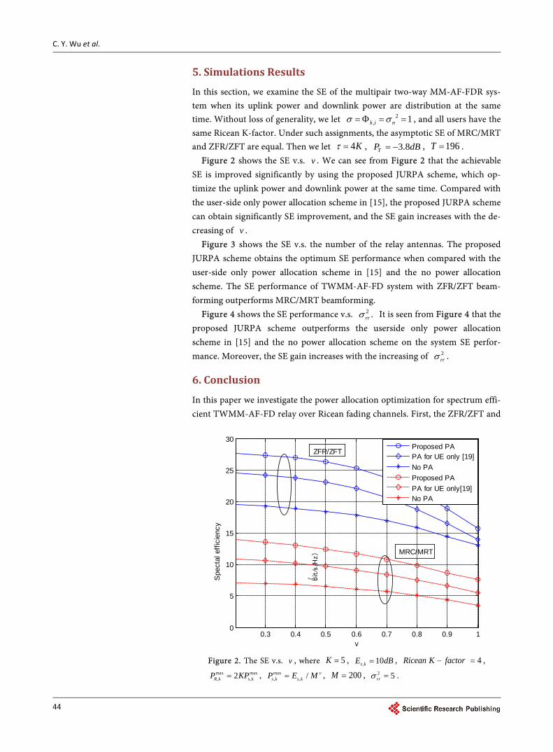
Figure 2 shows the SE v.s. v . We can see from Figure 2 that the achievable SE is improved significantly by using the proposed JURPA scheme, which op-timize the uplink power and downlink power at the same time. Compared with the user-side only power allocation scheme in [15], the proposed JURPA scheme can obtain significantly SE improvement, and the SE gain increases with the de-creasing of v .
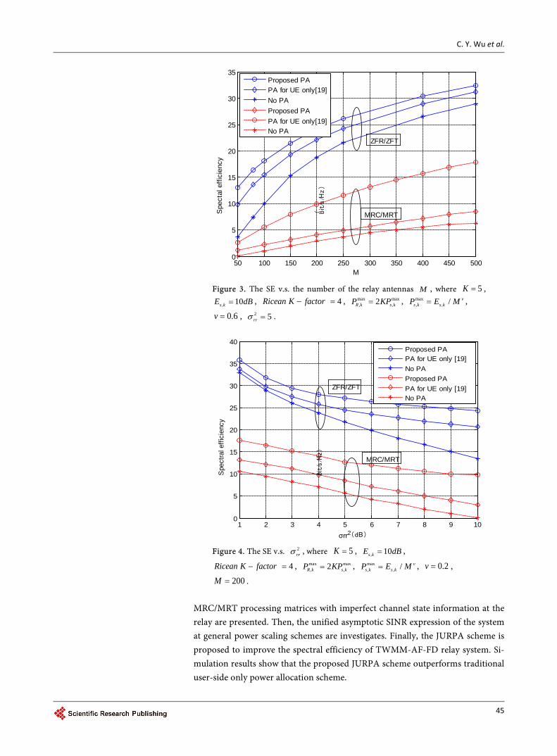
Figure 3 shows the SE v.s. the number of the relay antennas. The proposed JURPA scheme obtains the optimum SE performance when compared with the user-side only power allocation scheme in [15] and the no power allocation scheme. The SE performance of TWMM-AF-FD system with ZFR/ZFT beam-forming outperforms MRC/MRT beamforming.
Figure 4 shows the SE performance v.s. 2 .rrσ It is seen from Figure 4 that the proposed JURPA scheme outperforms the userside only power allocation scheme in [15] and the no power allocation scheme on the system SE perfor-mance. Moreover, the SE gain increases with the increasing of 2
rrσ .
6. Conclusion
In this paper we investigate the power allocation optimization for spectrum effi-cient TWMM-AF-FD relay over Ricean fading channels. First, the ZFR/ZFT and
Figure 2. The SE v.s. v , where 5K = , , 10s kE dB= , 4Ricean K factor− = ,
max max, ,2R k s kP KP= , max
, , / vs k s kP E M= , 200M = , 2 5rrσ = .
0.3 0.4 0.5 0.6 0.7 0.8 0.9 10
5
10
15
20
25
30
Spe
ctal
effi
cien
cy
( bit/s
/Hz)
v
Proposed PAPA for UE only [19]No PAProposed PA PA for UE only[19]No PA
ZFR/ZFT
MRC/MRT
C. Y. Wu et al.
45
Figure 3. The SE v.s. the number of the relay antennas M , where 5K = ,
, 10s kE dB= , 4Ricean K factor− = , max max, ,2R k s kP KP= , max
, , / vs k s kP E M= ,
0.6v = , 2 5rrσ = .
Figure 4. The SE v.s. 2
rrσ , where 5K = , , 10s kE dB= ,
4Ricean K factor− = , max max, ,2R k s kP KP= , max
, , / vs k s kP E M= , 0.2v = ,
200M = . MRC/MRT processing matrices with imperfect channel state information at the relay are presented. Then, the unified asymptotic SINR expression of the system at general power scaling schemes are investigates. Finally, the JURPA scheme is proposed to improve the spectral efficiency of TWMM-AF-FD relay system. Si-mulation results show that the proposed JURPA scheme outperforms traditional user-side only power allocation scheme.
50 100 150 200 250 300 350 400 450 5000
5
10
15
20
25
30
35
M
Spe
ctal
effi
cien
cy
( bit/s/H
z)
Proposed PAPA for UE only[19]No PAProposed PAPA for UE only[19]No PA
ZFR/ZFT
MRC/MRT
1 2 3 4 5 6 7 8 9 100
5
10
15
20
25
30
35
40
Spec
tral e
ffici
ency
( bit/s
/Hz)
σrr2(dB)
Proposed PAPA for UE only [19]No PAProposed PA PA for UE only [19]No PA
ZFR/ZFT
MRC/MRT

C. Y. Wu et al.
46
Acknowledgements
This work is supported by Jiangsu Province Natural Science Foundation under Grant BK20160079, National Natural Science Foundation of China (No. 61671472, 91438115, No. 61371123).
References [1] Marzetta, T.L. (2010) Noncooperative Cellular Wireless with Unlimited Numbers of
BS Antennas. IEEE Transactions on Wireless Communications, 9, 3590-3600. https://doi.org/10.1109/TWC.2010.092810.091092
[2] Ngo, H.Q., Larsson, E.G. and Marzetta, T.L. (2013) Energy and Spectral Efficiency of Very Large Multiuser MIMO Systems. IEEE Transactions on Communications, 61, 1436-1449. https://doi.org/10.1109/TCOMM.2013.020413.110848
[3] Hoydis, J., Brink, S., and Debbah, M. (2013) Massive MIMO in UL/DL of Cellular Networks: How Many Antennas Do We Need? IEEE Journal on Selected Areas in Communications, 31, 160-171. https://doi.org/10.1109/JSAC.2013.130205
[4] Zhang, J., Wen, C.K., Jin, S., Gao, X. and Wong, K. (2013) On Capacity of Large Scale MIMO Multiple Access Channels with Distributed Sets of Correlated Anten-nas. IEEE Journal on Selected Areas in Communications, 31, 133-148. https://doi.org/10.1109/JSAC.2013.130203
[5] Sun, X., Xu, K., Xie, W. and Xu, Y. (2016) Multi-Pair Two-Way Massive MIMO AF Relaying with MRC/MRT and Imperfect CSI. 2016 IEEE/CIC International Confe-rence on Communications in China (ICCC), Chengdu, 27-29 July 2016, 1-6. https://doi.org/10.1109/ICCChina.2016.7636719
[6] You, L., Gao, X., Xia, X.G., Ma, N. and Peng, Y. (2015) Pilot Reuse for Massive MIMO Transmission over Spatially Correlated Rayleigh Fading Channels. IEEE Transactions on Wireless Communications, 14, 3352-3366. https://doi.org/10.1109/TWC.2015.2404839
[7] Jin, S., Liang, X., Wong, K.K., Gao, X. and Zhu, Q. (2015) Ergodic Rate Analysis for Multipair Massive MIMO Two-Way Relay Networks. IEEE Transactions on Wire-less Communications, 14, 1480-1491. https://doi.org/10.1109/TWC.2014.2367503
[8] Adhikary, A., Nam, J., Ahn, J.-Y. and Caire, G. (2013) Joint Spatial Division and Multiplexing: The Large-Scale Array Regime. IEEE Transactions on Information Theory, 59, 6441-6463. https://doi.org/10.1109/TIT.2013.2269476
[9] Sun, C., Gao, X., Jin, S., Matthaiou, M., Ding, Z. and Xiao, C. (2015) Beam Division Multiple Access Transmission for Massive MIMO Communications. IEEE Transac-tions on Communications, 63, 2170-2184. https://doi.org/10.1109/TCOMM.2015.2425882
[10] Sabharwal, A., Schniter, P., Guo, D., Bliss, D.W., Rangarajan, S. and Wichman, R. (2014) In-Band Full-Duplex Wireless: Challenges and Opportunities. IEEE Journal on Selected Areas in Communications, 32, 1637-1652. https://doi.org/10.1109/JSAC.2014.2330193
[11] Ngo, H.Q., Suraweera, H.A., Matthaiou, M. and Larsson, E.G. (2014) Multipair Full-Duplex Relaying with Massive Arrays and Linear Processing. IEEE Journal on Selected Areas in Communications, 32, 1721-1737. https://doi.org/10.1109/JSAC.2014.2330091
[12] Zheng, G. (2015) Joint Beamforming Optimization and Power Control for Fulldup-lex MIMO Two-Way Relay Channel. IEEE Transactions on Signal Processing, 63, 555-566. https://doi.org/10.1109/TSP.2014.2376885
C. Y. Wu et al.
47
[13] Jang, Y., Min, K., Park, S. and Choi, S. (2015) Spatial Resource Utilization to Max-imize Uplink Spectral Efficiency in Full-Duplex Massive MIMO. 2015 IEEE Interna-tional Conference on Communications (ICC), London, 8-12 June 2015, 1583-1588. https://doi.org/10.1109/ICC.2015.7248550
[14] Mai, R., Nguyen, D.H.N. and Le-Ngoc, T. (2016) Joint MSE-Based Hybrid Precoder and Equalizer Design for Full-Duplex Massive MIMO Systems. 2016 IEEE Interna-tional Conference on Communications (ICC), Kuala Lumpur, 22-27 May 2016, 1-6. https://doi.org/10.1109/ICC.2016.7511185
[15] Sun, X., Xu, K., Ma, W., Xu, Y., Xia, X. and Zhang, D. (2016) Multi-Pair Two-Way Massive MIMO AF Full-Duplex Relaying with Imperfect CSI over Ricean Fading Channels. IEEE Access, 4, 4933-4945. https://doi.org/10.1109/ACCESS.2016.2595590
[16] Zhang, Z., Chen, Z., Shen, M., Xia, B. and Luo, L. (2015) Achievable Rate Analysis for Multi-Pair Two-Way Massive MIMO Full-Duplex Relay Systems. Proceedings of IEEE International Symposium on Information Theory, Hong Kong, 14-19 June 2015, 2598-2602. https://doi.org/10.1109/ISIT.2015.7282926
[17] Zhang, Q., Jin, S., Wong, K.-K., Zhu, H. and Matthaiou, M. (2014) Power Scaling of Uplink Massive MIMO Systems with Arbitrary-Rank Channel Means. IEEE Journal of Selected Topics in Signal Processing, 8, 966-981. https://doi.org/10.1109/JSTSP.2014.2324534
[18] Cui, H., Song, L. and Jiao, B. (2014) Multi-Pair Two-Way Amplify-and-Forward Relaying with Very Large Number of Relay Antennas. IEEE Transactions on Wire-less Communications, 13, 2636-2645. https://doi.org/10.1109/TWC.2014.032514.130885
[19] Weeraddana, P.C., Codreanu, M., Latva-Aho, M. and Ephremides, A. (2011) Re-source Allocation for Cross-Layer Utility Maximization in Wireless Networks. IEEE Transactions on Vehicular Technology, 60, 2790-2809. https://doi.org/10.1109/TVT.2011.2157544
Submit or recommend next manuscript to SCIRP and we will provide best service for you:
Accepting pre-submission inquiries through Email, Facebook, LinkedIn, Twitter, etc. A wide selection of journals (inclusive of 9 subjects, more than 200 journals) Providing 24-hour high-quality service User-friendly online submission system Fair and swift peer-review system Efficient typesetting and proofreading procedure Display of the result of downloads and visits, as well as the number of cited articles Maximum dissemination of your research work
Submit your manuscript at: http://papersubmission.scirp.org/ Or contact [email protected]
Recommended