Operator’s Manual
REF 10379682
+

134798 Rev. A, 2009 07
Operator’s Manual
+
© 2009 Siemens Healthcare Diagnostics Inc.All rights reserved.
Clinitek, Clinitek Status, Multistix, Multistix PRO, Combistix, Uristix,Labstix, Neostix, Clinitest and Chek-Stix are trademarks ofSiemens Healthcare Diagnostics.
Presept and Cidex are trademarks of Johnson & Johnson.
Theracide is a trademark of Lafayette Pharmaceuticals, Inc.
Amphyl is a trademark of Linden Corporation.
Kimwipes is a trademark of Kimberly-Clark.
US Pats 5,408,535; 5,477,326; 5,877,863; 6,239,445; D456,082; D489,816
Origin: UK
The information in this manual was correct at the time of printing.However, Siemens Healthcare Diagnostics continues to improve productsand reserves the right to change specifications, equipment, andmaintenance procedures at any time without notice.
If this instrument is used in a manner differently than specifiedin this manual, the protection provided by the equipment maybe impaired.
Siemens Healthcare Diagnostics Ltd.Sir William Siemens Sq.Frimley, Camberley, GU16 8QD, UK
Siemens Healthcare Diagnostics Inc.Tarrytown, NY 10591-5097 USA
iii
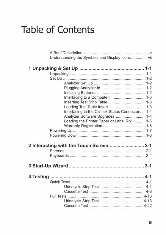
Table of Contents
A Brief Description ............................................................ vUnderstanding the Symbols and Display Icons .............. vii
1 Unpacking & Set Up ................................................. 1-1Unpacking .....................................................................1-1Set Up ...........................................................................1-2
Analyzer Set Up ...............................................1-2Plugging Analyzer In ........................................1-2Installing Batteries ............................................1-2Interfacing to a Computer .................................1-3Inserting Test Strip Table ..................................1-3Loading Test Table Insert .................................1-3Interfacing to the Clinitek Status Connector .....1-4Analyzer Software Upgrades ...........................1-4Loading the Printer Paper or Label Roll ...........1-5Warranty Registration .......................................1-6
Powering Up ..................................................................1-7Powering Down .............................................................1-8
2 Interacting with the Touch Screen .......................... 2-1Screens .........................................................................2-1Keyboards .....................................................................2-4
3 Start-Up Wizard ......................................................... 3-1
4 Testing ....................................................................... 4-1Quick Tests ....................................................................4-1
Urinalysis Strip Test ..........................................4-1Cassette Test ....................................................4-8
Full Tests .....................................................................4-13Urinalysis Strip Test ........................................4-13Cassette Test ..................................................4-22
iv
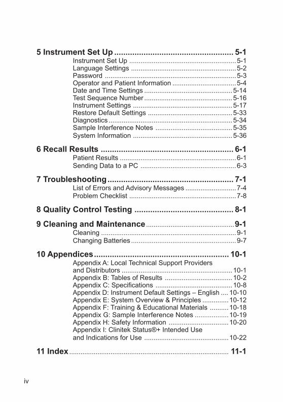
5 Instrument Set Up ..................................................... 5-1Instrument Set Up .........................................................5-1Language Settings ........................................................5-2Password ......................................................................5-3Operator and Patient Information ..................................5-4Date and Time Settings ...............................................5-14Test Sequence Number ...............................................5-16Instrument Settings .....................................................5-17Restore Default Settings .............................................5-33Diagnostics ..................................................................5-34Sample Interference Notes .........................................5-35System Information .....................................................5-36
6 Recall Results ........................................................... 6-1Patient Results ..............................................................6-1Sending Data to a PC ...................................................6-3
7 Troubleshooting........................................................ 7-1List of Errors and Advisory Messages ...........................7-4Problem Checklist .........................................................7-8
8 Quality Control Testing ............................................ 8-1
9 Cleaning and Maintenance ...............................................9-1Cleaning ........................................................................9-1Changing Batteries ........................................................9-7
10 Appendices............................................................ 10-1Appendix A: Local Technical Support Providersand Distributors ...........................................................10-1Appendix B: Tables of Results ....................................10-2Appendix C: Specifications .........................................10-8Appendix D: Instrument Default Settings – English .... 10-10Appendix E: System Overview & Principles ..............10-12Appendix F: Training & Educational Materials ..........10-18Appendix G: Sample Interference Notes ..................10-19Appendix H: Safety Information ................................10-20Appendix I: Clinitek Status®+ Intended Useand Indications for Use .............................................10-22
11 Index ..................................................................................... 11-1
v
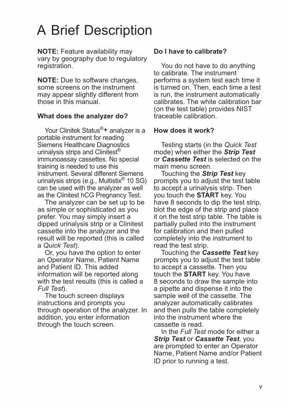
NOTE: Feature availability mayvary by geography due to regulatoryregistration.
NOTE: Due to software changes,some screens on the instrumentmay appear slightly different fromthose in this manual.
What does the analyzer do?
Your Clinitek Status®+ analyzer is aportable instrument for readingSiemens Healthcare Diagnosticsurinalysis strips and Clinitest®
immunoassay cassettes. No specialtraining is needed to use thisinstrument. Several different Siemensurinalysis strips (e.g., Multistix® 10 SG)can be used with the analyzer as wellas the Clinitest hCG Pregnancy Test.
The analyzer can be set up to beas simple or sophisticated as youprefer. You may simply insert adipped urinalysis strip or a Clinitestcassette into the analyzer and theresult will be reported (this is calleda Quick Test).
Or, you have the option to enteran Operator Name, Patient Nameand Patient ID. This addedinformation will be reported alongwith the test results (this is called aFull Test).
The touch screen displaysinstructions and prompts youthrough operation of the analyzer. Inaddition, you enter informationthrough the touch screen.
Do I have to calibrate?
You do not have to do anythingto calibrate. The instrumentperforms a system test each time itis turned on. Then, each time a testis run, the instrument automaticallycalibrates. The white calibration bar(on the test table) provides NISTtraceable calibration.
How does it work?
Testing starts (in the Quick Testmode) when either the Strip Testor Cassette Test is selected on themain menu screen.
Touching the Strip Test keyprompts you to adjust the test tableto accept a urinalysis strip. Thenyou touch the START key. Youhave 8 seconds to dip the test strip,blot the edge of the strip and placeit on the test strip table. The table ispartially pulled into the instrumentfor calibration and then pulledcompletely into the instrument toread the test strip.
Touching the Cassette Test keyprompts you to adjust the test tableto accept a cassette. Then youtouch the START key. You have8 seconds to draw the sample intoa pipette and dispense it into thesample well of the cassette. Theanalyzer automatically calibratesand then pulls the table completelyinto the instrument where thecassette is read.
In the Full Test mode for either aStrip Test or Cassette Test, youare prompted to enter an OperatorName, Patient Name and/or PatientID prior to running a test.
A Brief Description
vi
A Brief Description
How do I get results?
Results will be displayed on thetouch screen and printed (ifdesired). The results can also betransferred to a computer using a9-pin null modem serial cable andthe RS-232 serial port on the backof the instrument.
The analyzer stores results from950 patient tests. You are able torecall past patient test results onthe analyzer using the RecallResults function.
How is the analyzer powered?
The analyzer can be pluggedinto an electrical outlet for use onthe bench top, or it can be poweredby batteries and freely moved fromone testing site to another. Thebatteries fit into an opening on thebottom of the instrument.
What about this Operator’sManual?
The Operator’s Manual containsthe directions you need to unpack
the analyzer, use it for your dailySiemens urinalysis and Clinitestimmunoassay testing and keep it ingood working condition.
As you read through theOperator’s Manual, you will findthese symbols:
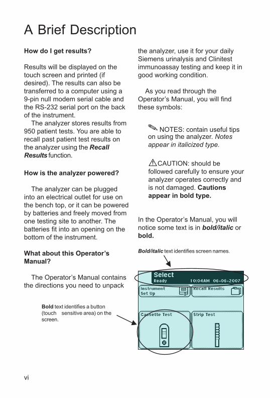
In the Operator’s Manual, you willnotice some text is in bold/italic orbold.
Bold/italic text identifies screen names.
NOTES: contain useful tipson using the analyzer. Notesappear in italicized type.
Bold text identifies a button(touch sensitive area) on thescreen.
CAUTION: should befollowed carefully to ensure youranalyzer operates correctly andis not damaged. Cautionsappear in bold type.
vii
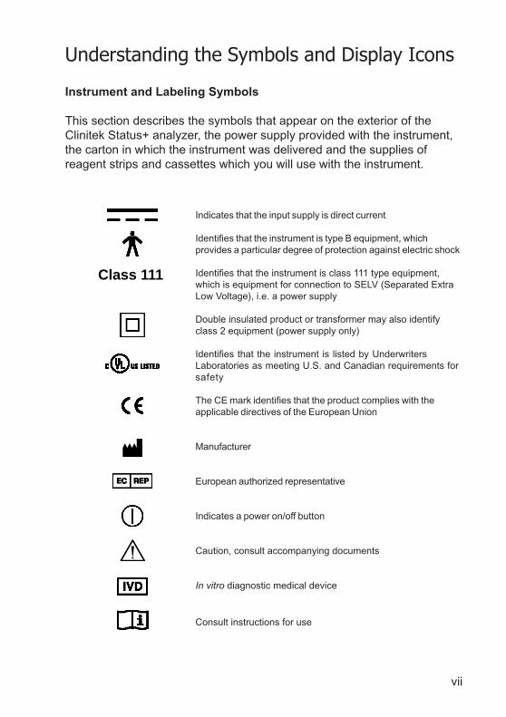
Instrument and Labeling Symbols
This section describes the symbols that appear on the exterior of theClinitek Status+ analyzer, the power supply provided with the instrument,the carton in which the instrument was delivered and the supplies ofreagent strips and cassettes which you will use with the instrument.
Indicates that the input supply is direct current
Identifies that the instrument is type B equipment, whichprovides a particular degree of protection against electric shock
Identifies that the instrument is class 111 type equipment,which is equipment for connection to SELV (Separated ExtraLow Voltage), i.e. a power supply
Double insulated product or transformer may also identifyclass 2 equipment (power supply only)
Identifies that the instrument is listed by UnderwritersLaboratories as meeting U.S. and Canadian requirements forsafety
The CE mark identifies that the product complies with theapplicable directives of the European Union
Manufacturer
European authorized representative
Indicates a power on/off button
Caution, consult accompanying documents
In vitro diagnostic medical device
Consult instructions for use
Understanding the Symbols and Display Icons
Class 111
viii
Understanding the Symbols and Display Icons
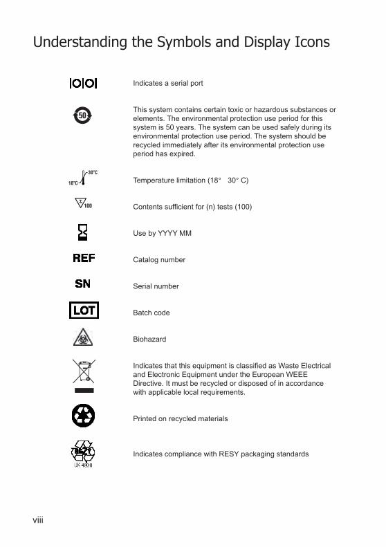
Indicates a serial port
This system contains certain toxic or hazardous substances orelements. The environmental protection use period for thissystem is 50 years. The system can be used safely during itsenvironmental protection use period. The system should berecycled immediately after its environmental protection useperiod has expired.
Temperature limitation (18° 30° C)
Contents sufficient for (n) tests (100)
Use by YYYY MM
Catalog number
Serial number
Batch code
Biohazard
Indicates that this equipment is classified as Waste Electricaland Electronic Equipment under the European WEEEDirective. It must be recycled or disposed of in accordancewith applicable local requirements.
Printed on recycled materials
Indicates compliance with RESY packaging standards
100
18
30

ix
Understanding the Symbols and Display Icons
VDE Testing and Certification Institute Germany
Manufacturer’s mark (FRIWO) and manufacturing location(Hong Kong)
Manufacturer’s mark (FRIWO) and manufacturing location(Geratebau, Germany)
Encapsulated safety isolating transformer (short circuit proof)
Positive Temperature Coefficient (PTC) A thermistor deviceused to protect the transformer from short circuits or overload.This is an auto reset device.
Thermal cut out (TCO) This safety device disconnects thesupply voltage to the transformer at a specific temperature.The operation temperature is stated below.
Ingress protection rating protected against the entry of solidobjects >1 mm but no protection from liquids.
This symbol indicates a risk of electric shock.
Keep this way up
Fragile, handle with care
Keep dry
Keep away from sunlight and heat
x
Understanding the Symbols and Display Icons
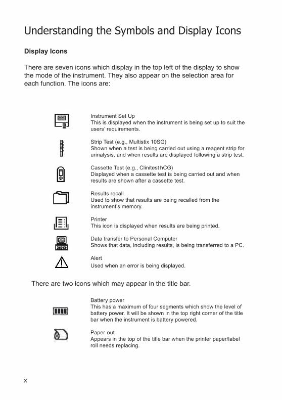
Display Icons
There are seven icons which display in the top left of the display to showthe mode of the instrument. They also appear on the selection area foreach function. The icons are:
Instrument Set UpThis is displayed when the instrument is being set up to suit theusers’ requirements.
Strip Test (e.g., Multistix 10SG)Shown when a test is being carried out using a reagent strip forurinalysis, and when results are displayed following a strip test.
Cassette Test (e.g., Clinitest hCG)Displayed when a cassette test is being carried out and whenresults are shown after a cassette test.
Results recallUsed to show that results are being recalled from theinstrument’s memory.
PrinterThis icon is displayed when results are being printed.
Data transfer to Personal ComputerShows that data, including results, is being transferred to a PC.
AlertUsed when an error is being displayed.
There are two icons which may appear in the title bar.
Battery powerThis has a maximum of four segments which show the level ofbattery power. It will be shown in the top right corner of the titlebar when the instrument is battery powered.
Paper outAppears in the top of the title bar when the printer paper/labelroll needs replacing.
1-1
1 Unpacking & Set Up
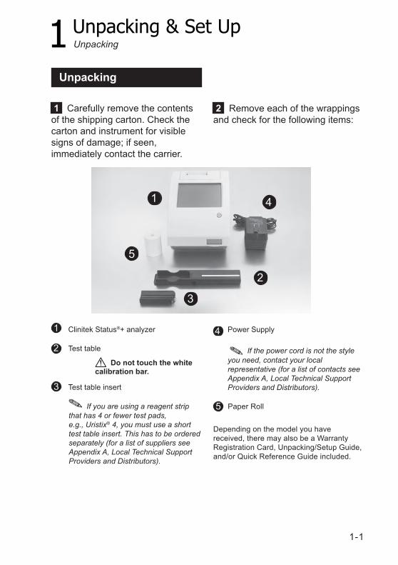
Clinitek Status®+ analyzer
Test table
Test table insert
Unpacking
2 Remove each of the wrappingsand check for the following items:
1 Carefully remove the contentsof the shipping carton. Check thecarton and instrument for visiblesigns of damage; if seen,immediately contact the carrier.
41
5
3
2
Paper Roll
Depending on the model you havereceived, there may also be a WarrantyRegistration Card, Unpacking/Setup Guide,and/or Quick Reference Guide included.
2
5 If you are using a reagent stripthat has 4 or fewer test pads,e.g., Uristix® 4, you must use a shorttest table insert. This has to be orderedseparately (for a list of suppliers seeAppendix A, Local Technical SupportProviders and Distributors).
Do not touch the whitecalibration bar.
If the power cord is not the styleyou need, contact your localrepresentative (for a list of contacts seeAppendix A, Local Technical SupportProviders and Distributors).
1
Unpacking
3
4 Power Supply
1-2
1 Unpacking & Set Up
Set Up
Analyzer Set Up
Place the instrument on a levelwork surface where thetemperature and humidity are fairlyconstant.
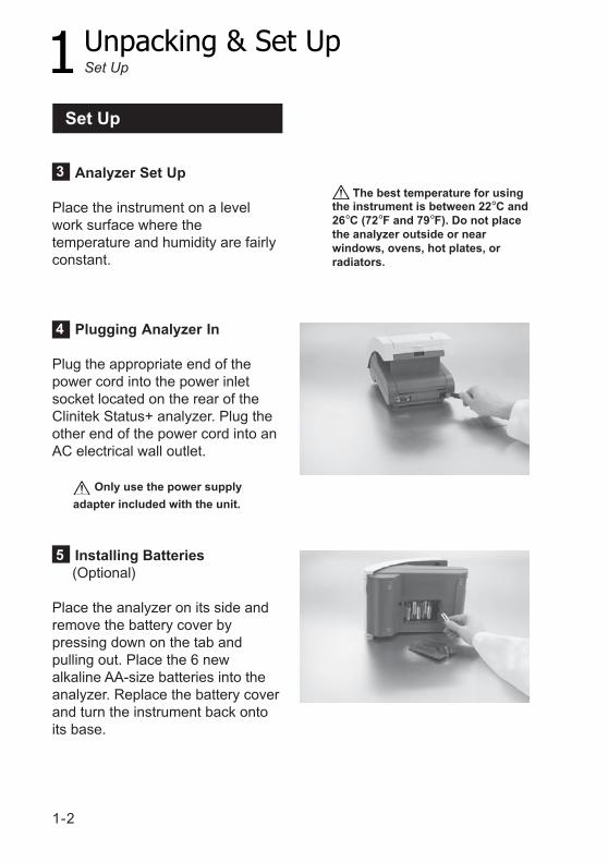
Plugging Analyzer In
Plug the appropriate end of thepower cord into the power inletsocket located on the rear of theClinitek Status+ analyzer. Plug theother end of the power cord into anAC electrical wall outlet.
Only use the power supply
adapter included with the unit.
Installing Batteries (Optional)
Place the analyzer on its side andremove the battery cover bypressing down on the tab andpulling out. Place the 6 newalkaline AA-size batteries into theanalyzer. Replace the battery coverand turn the instrument back ontoits base.
The best temperature for usingthe instrument is between 22°C and26°C (72°F and 79°F). Do not placethe analyzer outside or nearwindows, ovens, hot plates, orradiators.
5
3
4
Set Up
1-3
1 Unpacking & Set Up
Do not touch the whitecalibration bar.
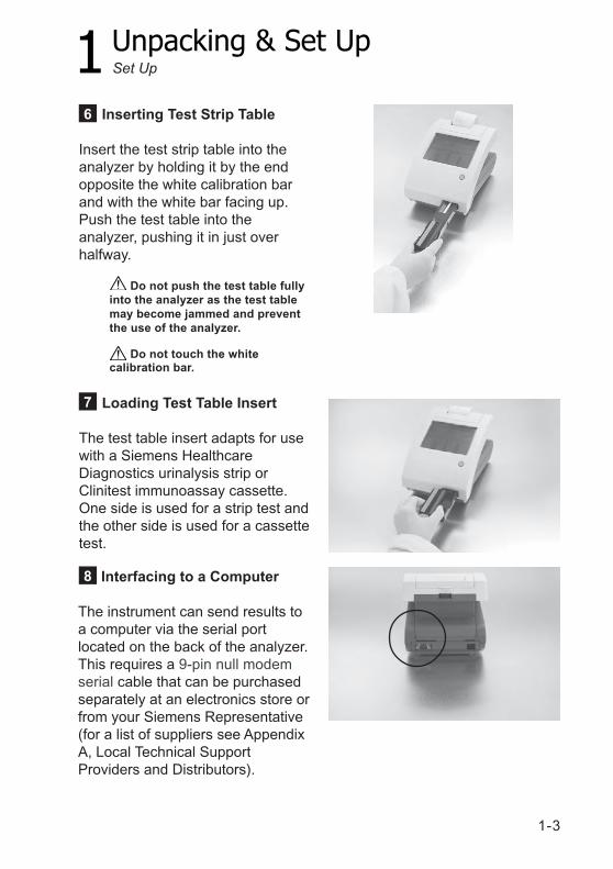
Inserting Test Strip Table
Insert the test strip table into theanalyzer by holding it by the endopposite the white calibration barand with the white bar facing up.Push the test table into theanalyzer, pushing it in just overhalfway.
Loading Test Table Insert
The test table insert adapts for usewith a Siemens HealthcareDiagnostics urinalysis strip orClinitest immunoassay cassette.One side is used for a strip test andthe other side is used for a cassettetest.
6
7
8
Set Up
Interfacing to a Computer
The instrument can send results toa computer via the serial portlocated on the back of the analyzer.This requires a 9-pin null modemserial cable that can be purchasedseparately at an electronics store orfrom your Siemens Representative(for a list of suppliers see AppendixA, Local Technical SupportProviders and Distributors).
Do not push the test table fullyinto the analyzer as the test tablemay become jammed and preventthe use of the analyzer.
1-4
1 Unpacking & Set Up
Interfacing to theClinitek Status Connector
The Clinitek Status connectorallows for Ethernet or wirelessnetwork connectivity, QualityControl, increased security, barcode scanning, and additionalfeatures with the Clinitek Status+analyzer.This connector provides standardwired and wireless connectivity ofthe Clinitek Status+ system to yourLAN, LIS, HIS, EMR, and allowsfor centralized control of allsatellite Point of Care (POC)Clinitek Status+ analyzers.Refer to the Clinitek StatusConnect System Operator’s Guide.
Analyzer Software Upgrades
From time to time Siemens will addnew features and make improvementsto the Clinitek Status+ instrumentsoftware.
These software updates will beavailable on an electronic memorycard which is inserted into thesoftware update socket. This socketis located under the printer coverand is on the left-hand side of theprinter when you face the back ofthe instrument.
Updating the software is a simpleprocedure. Instructions for updatingthe software on your instrument willbe supplied with the memory card.
Set Up
9
10
1-5
1 Unpacking & Set Up
Loading the Printer Paper orLabel Roll
1. Open the printer cover by pullingup on the tab.
2. Open the paper roll compartmentcover by pressing down on its taband pulling out.
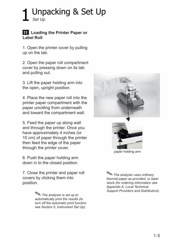
3. Lift the paper holding arm intothe open, upright position.
4. Place the new paper roll into theprinter paper compartment with thepaper unrolling from underneathand toward the compartment wall.
5. Feed the paper up along walland through the printer. Once youhave approximately 4 inches (or10 cm) of paper through the printerthen feed the edge of the paperthrough the printer cover.
6. Push the paper holding armdown in to the closed position.
7. Close the printer and paper rollcovers by clicking them intoposition.
The analyzer is set up toautomatically print the results (toturn off the automatic print functionsee Section 5, Instrument Set Up).
paper holding arm
The analyzer uses ordinarythermal paper as provided, or labelstock (for ordering information seeAppendix A, Local TechnicalSupport Providers and Distributors).
Set Up
11
1-6
1 Unpacking & Set Up
Warranty Registration
1. Lift the printer cover on theinstrument and the serial plate withthe instrument’s serial number willbe visible.
2. Write the serial number andinstallation date on the WarrantyRegistration Card. After theinstrument has been successfullyinstalled, complete the informationon the Warranty Registration Cardand return the card to your localSiemens office (for a contact listsee Appendix A, Local TechnicalSupport Providers andDistributors).
12
Set Up
1-7
1 Unpacking & Set Up
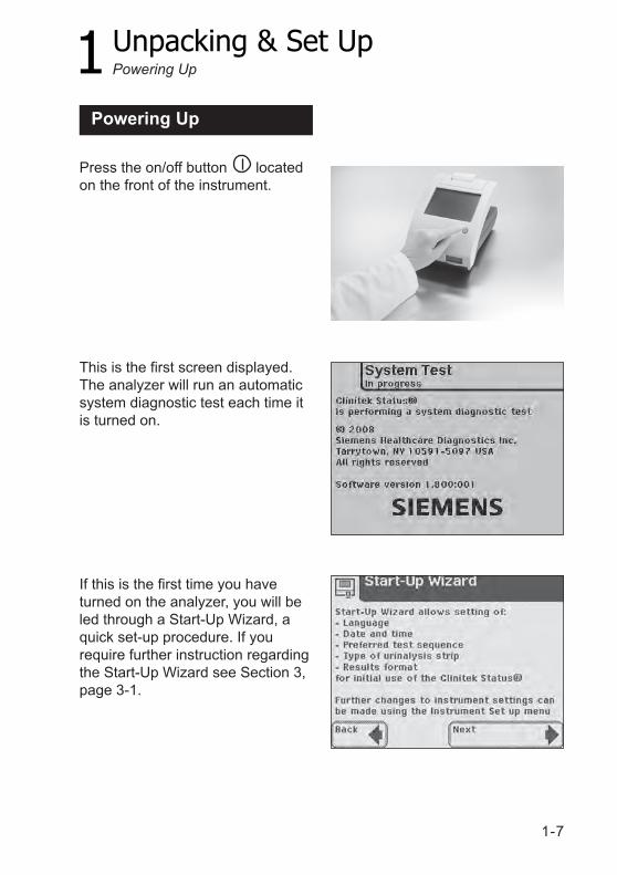
Press the on/off button locatedon the front of the instrument.
This is the first screen displayed.The analyzer will run an automaticsystem diagnostic test each time itis turned on.
If this is the first time you haveturned on the analyzer, you will beled through a Start-Up Wizard, aquick set-up procedure. If yourequire further instruction regardingthe Start-Up Wizard see Section 3,page 3-1.
Powering Up
Powering Up
1-8
1 Unpacking & Set Up
Powering Down
Powering Down
1. Before turning the analyzer off,always ensure that there is no stripor cassette on the test table andthat the table and insert are clean.
2. Press the on/off button forat least 2 seconds. The test tablewill retract into the analyzer. If thereis no strip or cassette on the testtable, the door will close and theanalyzer will switch off.
If a strip or cassette is still on thetest table, the test table will bepushed out and the analyzer willturn off. The test table will remainout. In order to retract the test tableinto the analyzer, turn the analyzeron, and then off (without a strip orcassette on the test table).
Do not push the test table fullyinto the analyzer as the test tablemay become jammed and preventthe use of the analyzer.
2-1
2 Interacting with the Touch Screen
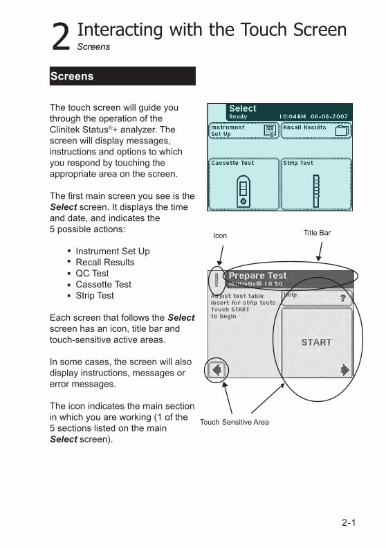
The touch screen will guide youthrough the operation of theClinitek Status®+ analyzer. Thescreen will display messages,instructions and options to whichyou respond by touching theappropriate area on the screen.
The first main screen you see is theSelect screen. It displays the timeand date, and indicates the5 possible actions:
Instrument Set UpRecall ResultsQC TestCassette TestStrip Test
Each screen that follows the Selectscreen has an icon, title bar andtouch-sensitive active areas.
In some cases, the screen will alsodisplay instructions, messages orerror messages.
The icon indicates the main sectionin which you are working (1 of the5 sections listed on the mainSelect screen).
Touch Sensitive Area
Screens
Screens
Title BarIcon
2-2
2 Interacting with the Touch Screen
How to Touch the ScreensThe screen needs to be touchedlightly in the touch-sensitive area toactivate a response.
Where to Touch the ScreensThere are three types of areas thatrespond to touching the screen.
• Round Buttons• Boxed Areas• Scroll Arrows
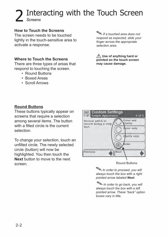
Round ButtonsThese buttons typically appear onscreens that require a selectionamong several items. The buttonwith a filled circle is the currentselection.
To change your selection, touch anunfilled circle. The newly selectedcircle (button) will now behighlighted. You then touch theNext button to move to the nextscreen.
If a touched area does notrespond as expected, slide yourfinger across the appropriateselection area.
Use of anything hard orpointed on the touch screenmay cause damage.
In order to proceed, you willalways touch the box with a rightpointed arrow labeled Next.
In order to go back, you willalways touch the box with a leftpointed arrow. These “back” optionboxes vary in title.
Round Buttons
Screens
2-3
2 Interacting with the Touch Screen
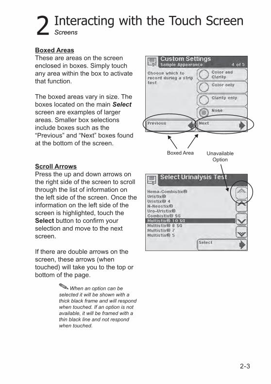
Boxed AreasThese are areas on the screenenclosed in boxes. Simply touchany area within the box to activatethat function.
The boxed areas vary in size. Theboxes located on the main Selectscreen are examples of largerareas. Smaller box selectionsinclude boxes such as the“Previous” and “Next” boxes foundat the bottom of the screen.
Scroll ArrowsPress the up and down arrows onthe right side of the screen to scrollthrough the list of information onthe left side of the screen. Once theinformation on the left side of thescreen is highlighted, touch theSelect button to confirm yourselection and move to the nextscreen.
If there are double arrows on thescreen, these arrows (whentouched) will take you to the top orbottom of the page.
When an option can beselected it will be shown with athick black frame and will respondwhen touched. If an option is notavailable, it will be framed with athin black line and not respondwhen touched.
UnavailableOption
Boxed Area
Screens
2-4
2 Interacting with the Touch Screen
Using the Alpha-NumericKeyboard
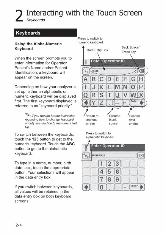
When the screen prompts you toenter information for Operator,Patient’s Name and/or PatientIdentification, a keyboard willappear on the screen.
Depending on how your analyzer isset up, either an alphabetic ornumeric keyboard will be displayedfirst. The first keyboard displayed isreferred to as “keyboard priority.”
To switch between the keyboards,touch the 123 button to get to thenumeric keyboard. Touch the ABCbutton to get to the alphabetickeyboard.
To type in a name, number, birthdate, etc., touch the appropriatebutton. Your selections will appearin the data entry box.
If you switch between keyboards,all values will be retained in thedata entry box on both keyboardscreens.
Keyboards
Data Entry BoxBack Space/Erase key
Confirmdataentries
Createsblankspace
Return topreviousscreen
If you require further instructionregarding how to change keyboardpriority see Section 5, Instrument SetUp.
Keyboards
Press to switch toalphabetic keyboard
Press to switch tonumeric keyboard
2-5
2 Interacting with the Touch Screen
The maximum number ofcharacters allowed is 32. Anaudible tone will sound when youhave exceeded the maximumnumber of characters.
Once you have finished enteringthe information, touch Enter (fromeither keyboard screen).
Keyboards

2-6
3-1
3 Start-Up Wizard
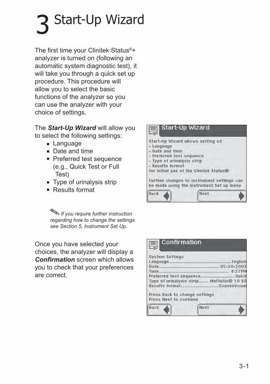
The first time your Clinitek Status®+analyzer is turned on (following anautomatic system diagnostic test), itwill take you through a quick set upprocedure. This procedure willallow you to select the basicfunctions of the analyzer so youcan use the analyzer with yourchoice of settings.
The Start-Up Wizard will allow youto select the following settings:
LanguageDate and timePreferred test sequence(e.g., Quick Test or Full
Test)Type of urinalysis stripResults format
Once you have selected yourchoices, the analyzer will display aConfirmation screen which allowsyou to check that your preferencesare correct.
If you require further instructionregarding how to change the settingssee Section 5, Instrument Set Up.

3-2
4 Testing
4-1
Quick Tests
Urinalysis Strip Test
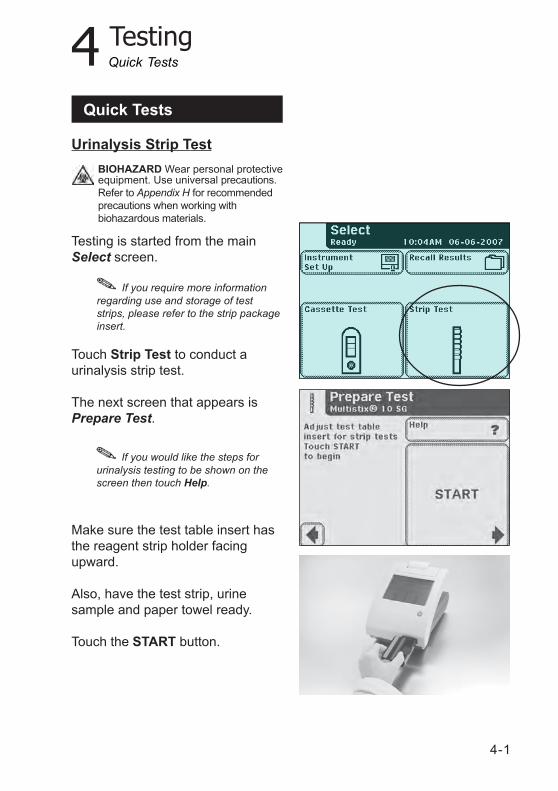
Testing is started from the mainSelect screen.
Touch Strip Test to conduct aurinalysis strip test.
The next screen that appears isPrepare Test.
Make sure the test table insert hasthe reagent strip holder facingupward.
Also, have the test strip, urinesample and paper towel ready.
Touch the START button.
If you require more informationregarding use and storage of teststrips, please refer to the strip packageinsert.
If you would like the steps forurinalysis testing to be shown on thescreen then touch Help.
Quick Tests
BIOHAZARD Wear personal protectiveequipment. Use universal precautions.Refer to Appendix H for recommendedprecautions when working withbiohazardous materials.
4-2
4 Testing
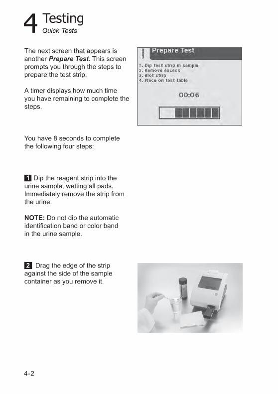
The next screen that appears isanother Prepare Test. This screenprompts you through the steps toprepare the test strip.
A timer displays how much timeyou have remaining to complete thesteps.
You have 8 seconds to completethe following four steps:
1 Dip the reagent strip into theurine sample, wetting all pads.Immediately remove the strip fromthe urine.
NOTE: Do not dip the automaticidentification band or color bandin the urine sample.
2 Drag the edge of the stripagainst the side of the samplecontainer as you remove it.
Quick Tests
4 Testing
4-3
Do not push or pull the testtable.
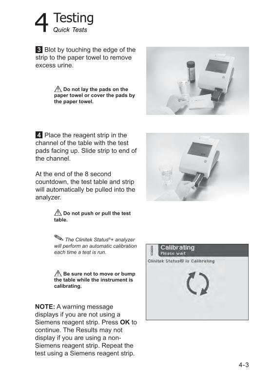
3 Blot by touching the edge of thestrip to the paper towel to removeexcess urine.
4 Place the reagent strip in thechannel of the table with the testpads facing up. Slide strip to end ofthe channel.
At the end of the 8 secondcountdown, the test table and stripwill automatically be pulled into theanalyzer.
Do not lay the pads on thepaper towel or cover the pads bythe paper towel.
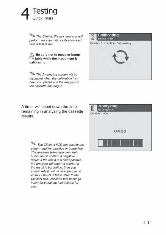
The Clinitek Status®+ analyzerwill perform an automatic calibrationeach time a test is run.
Be sure not to move or bumpthe table while the instrument iscalibrating.
Quick Tests
NOTE: A warning messagedisplays if you are not using aSiemens reagent strip. Press OK tocontinue. The Results may notdisplay if you are using a non-Siemens reagent strip. Repeat thetest using a Siemens reagent strip.
4-4
4 Testing
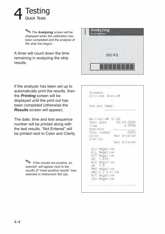
A timer will count down the timeremaining in analyzing the stripresults.
If the analyzer has been set up toautomatically print the results, thenthe Printing screen will bedisplayed until the print out hasbeen completed (otherwise theResults screen will appear).
The date, time and test sequencenumber will be printed along withthe test results. “Not Entered” willbe printed next to Color and Clarity.
If the results are positive, an
asterisk* will appear next to theresults (if “mark positive results” wasselected in Instrument Set Up).
Quick Tests
The Analyzing screen will bedisplayed when the calibration hasbeen completed and the analysis ofthe strip has begun.
4 Testing
4-5
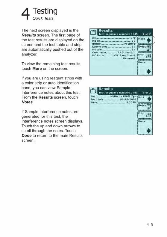
The next screen displayed is theResults screen. The first page ofthe test results are displayed on thescreen and the test table and stripare automatically pushed out of theanalyzer.
To view the remaining test results,touch More on the screen.
If you are using reagent strips witha color strip or auto identificationband, you can view SampleInterference notes about this test.From the Results screen, touchNotes.
If Sample Interference notes aregenerated for this test, theInterference notes screen displays.Touch the up and down arrows toscroll through the notes. TouchDone to return to the main Resultsscreen.
Quick Tests
4-6
4 Testing
Up to 5 Sample Interference notesdisplay on the screen. Use the upand down arrows to scroll throughthe notes. If enabled, the notesprint with the test results.
If Sample Interference notes havebeen disabled in the setup, theNOTES button does not display.
NOTE: If you run a test with thisfeature disabled, no notes will begenerated at the time of the actualtest. If you enable the sampleinterface notes then recall the testresults, the analyzer generatesSample Interference Notes for thispatient test.
If the analyzer has not been set upto automatically print the testresults, touch Print to have theresults printed.
The results will automatically besent to the connected PC if thisoption is set up in the analyzer.
If you require further instructionregarding how to set up the analyzerso the results are printed or sent to acomputer automatically see Section 5,Instrument Set Up.
Quick Tests
4 Testing
4-7
From the test table, remove theused urinalysis strip and dispose ofit according to your standardlaboratory procedures. Wipe thetable insert, if necessary.
Report the results to a laboratorysupervisor or physician.
Touch Done to complete the testand return to main Select screen.
The results will be displayed on
the screen for 2 minutes. After this timeelapses, the display will return to mainSelect menu.
Touch Done to return the Strip TestPrepare screen. You are ready tostart the next test. If testing iscomplete, touch Back key to returnto the Select menu.
Quick Tests
4-8
4 Testing
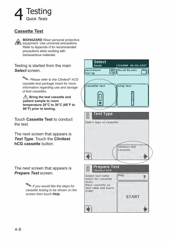
Cassette Test
Testing is started from the mainSelect screen.
Touch Cassette Test to conductthe test.
The next screen that appears isTest Type. Touch the ClinitesthCG cassette button.
The next screen that appears isPrepare Test screen.
If you would like the steps forcassette testing to be shown on thescreen then touch Help.
Bring the test cassette andpatient sample to roomtemperature 20°C to 30°C (68°F to86°F) prior to testing.
Please refer to the Clinitest® hCGcassette test package insert for moreinformation regarding use and storageof test cassettes.
Quick Tests
BIOHAZARD Wear personal protectiveequipment. Use universal precautions.Refer to Appendix H for recommendedprecautions when working withbiohazardous materials.
4 Testing
4-9
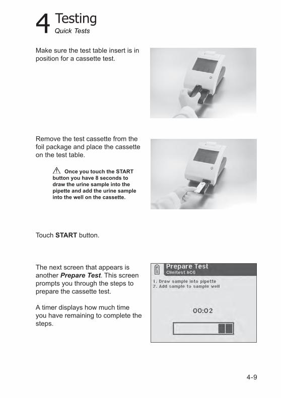
Make sure the test table insert is inposition for a cassette test.
Remove the test cassette from thefoil package and place the cassetteon the test table.
Touch START button.
The next screen that appears isanother Prepare Test. This screenprompts you through the steps toprepare the cassette test.
A timer displays how much timeyou have remaining to complete thesteps.
Once you touch the STARTbutton you have 8 seconds todraw the urine sample into thepipette and add the urine sampleinto the well on the cassette.
Quick Tests
4-10
4 Testing
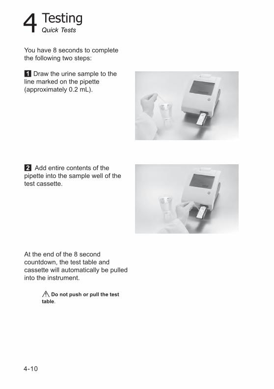
You have 8 seconds to completethe following two steps:
1 Draw the urine sample to theline marked on the pipette(approximately 0.2 mL).
2 Add entire contents of thepipette into the sample well of thetest cassette.
At the end of the 8 secondcountdown, the test table andcassette will automatically be pulledinto the instrument.
Do not push or pull the testtable.
Quick Tests
4 Testing
4-11
The Clinitek Status+ analyzer willperform an automatic calibration eachtime a test is run.
Be sure not to move or bumpthe table while the instrument iscalibrating.
The Analyzing screen will bedisplayed when the calibration hasbeen completed and the analysis ofthe cassette has begun.
The Clinitest hCG test results areeither negative, positive or borderline.The analyzer takes approximately5 minutes to confirm a negativeresult. If the result is a clear positive,the analyzer will report it sooner. Ifthe result is borderline, then youshould retest, with a new sample, in48 to 72 hours. Please refer to theClinitest hCG cassette test packageinsert for complete instructions foruse.
Quick Tests
A timer will count down the timeremaining in analyzing the cassetteresults.
4-12
4 Testing
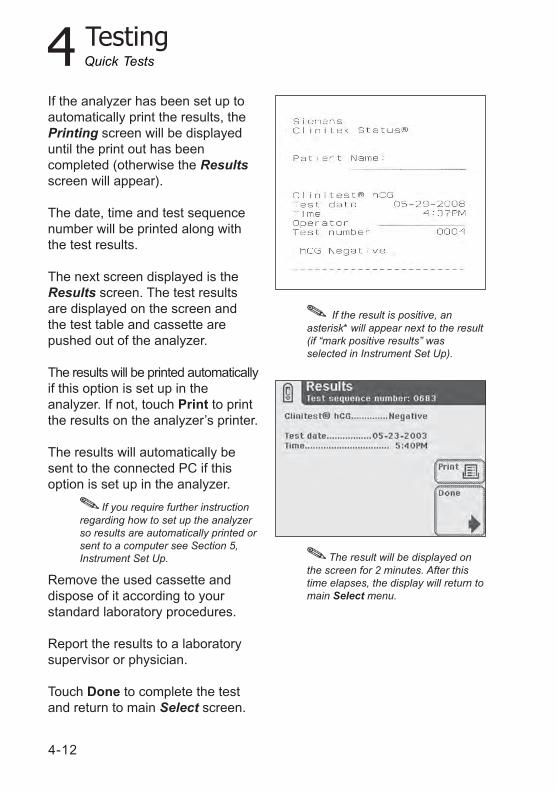
If the analyzer has been set up toautomatically print the results, thePrinting screen will be displayeduntil the print out has beencompleted (otherwise the Resultsscreen will appear).
The date, time and test sequencenumber will be printed along withthe test results.
The next screen displayed is theResults screen. The test resultsare displayed on the screen andthe test table and cassette arepushed out of the analyzer.
The results will be printed automaticallyif this option is set up in theanalyzer. If not, touch Print to printthe results on the analyzer’s printer.
The results will automatically besent to the connected PC if thisoption is set up in the analyzer.
Remove the used cassette anddispose of it according to yourstandard laboratory procedures.
Report the results to a laboratorysupervisor or physician.
Touch Done to complete the testand return to main Select screen.
If the result is positive, anasterisk* will appear next to the result(if “mark positive results” wasselected in Instrument Set Up).
The result will be displayed onthe screen for 2 minutes. After thistime elapses, the display will return tomain Select menu.
Quick Tests
If you require further instructionregarding how to set up the analyzerso results are automatically printed orsent to a computer see Section 5,Instrument Set Up.
4 Testing
4-13
Full Tests
Urinalysis Strip Test
A Full Strip Test allows you theoption to enter an Operator Name,Patient Name and/or Patient IDprior to inserting a strip.
The procedures to enter theOperator and Patient data arepresented in this section.
The strip testing process is identicalto a Quick Strip Test.
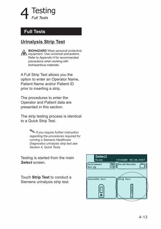
Testing is started from the mainSelect screen.
Touch Strip Test to conduct aSiemens urinalysis strip test.
If you require further instructionregarding the procedures required forrunning a Siemens HealthcareDiagnostics urinalysis strip test seeSection 4, Quick Tests.
Full Tests
BIOHAZARD Wear personal protectiveequipment. Use universal precautions.Refer to Appendix H for recommendedprecautions when working withbiohazardous materials.
4-14
4 Testing
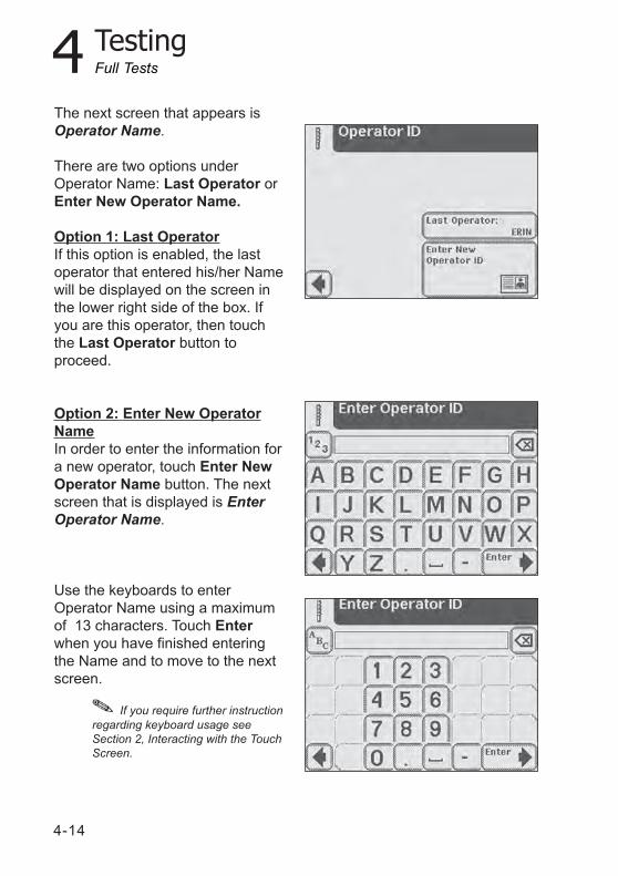
The next screen that appears isOperator Name.
There are two options underOperator Name: Last Operator orEnter New Operator Name.
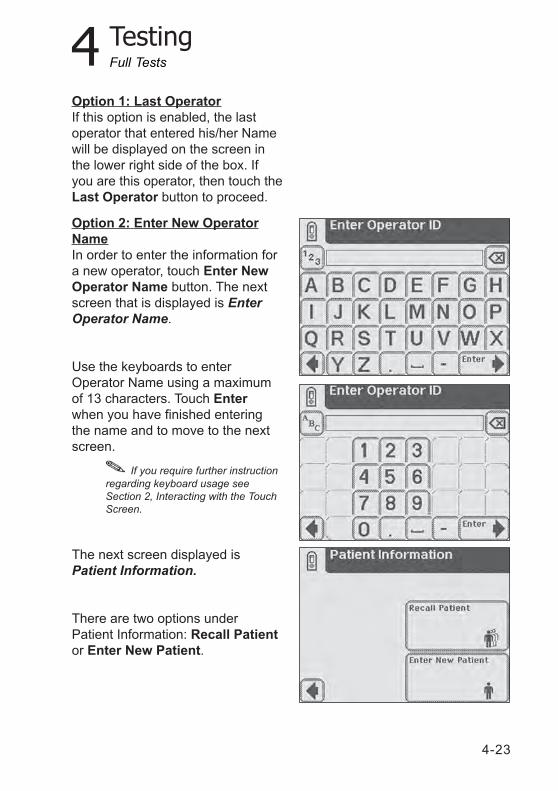
Option 1: Last Operator If this option is enabled, the lastoperator that entered his/her Namewill be displayed on the screen inthe lower right side of the box. Ifyou are this operator, then touchthe Last Operator button toproceed.
Option 2: Enter New OperatorNameIn order to enter the information fora new operator, touch Enter NewOperator Name button. The nextscreen that is displayed is EnterOperator Name.
Use the keyboards to enterOperator Name using a maximumof 13 characters. Touch Enterwhen you have finished enteringthe Name and to move to the nextscreen.
Full Tests
If you require further instructionregarding keyboard usage seeSection 2, Interacting with the TouchScreen.
4 Testing
4-15
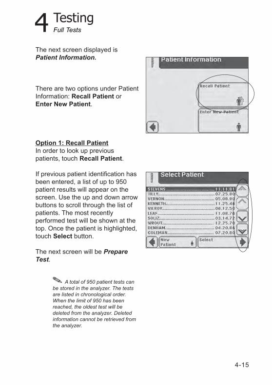
The next screen displayed isPatient Information.
There are two options under PatientInformation: Recall Patient orEnter New Patient.
Option 1: Recall PatientIn order to look up previouspatients, touch Recall Patient.
If previous patient identification hasbeen entered, a list of up to 950patient results will appear on thescreen. Use the up and down arrowbuttons to scroll through the list ofpatients. The most recentlyperformed test will be shown at thetop. Once the patient is highlighted,touch Select button.
The next screen will be PrepareTest.
A total of 950 patient tests canbe stored in the analyzer. The testsare listed in chronological order.When the limit of 950 has beenreached, the oldest test will bedeleted from the analyzer. Deletedinformation cannot be retrieved fromthe analyzer.
Full Tests
4-16
4 Testing
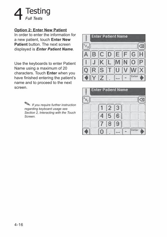
Option 2: Enter New PatientIn order to enter the information fora new patient, touch Enter NewPatient button. The next screendisplayed is Enter Patient Name.
Use the keyboards to enter PatientName using a maximum of 20characters. Touch Enter when youhave finished entering the patient’sname and to proceed to the nextscreen.
If you require further instructionregarding keyboard usage seeSection 2, Interacting with the TouchScreen.
Full Tests
4 Testing
4-17
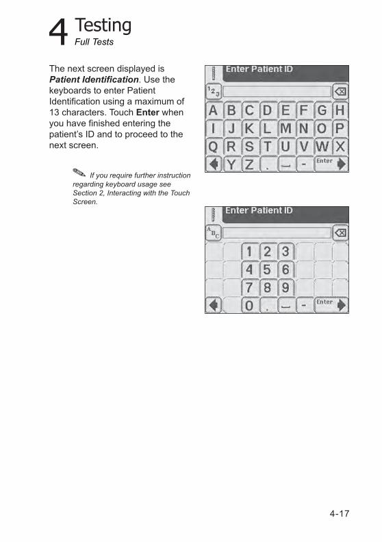
If you require further instructionregarding keyboard usage seeSection 2, Interacting with the TouchScreen.
The next screen displayed isPatient Identification. Use thekeyboards to enter PatientIdentification using a maximum of13 characters. Touch Enter whenyou have finished entering thepatient’s ID and to proceed to thenext screen.
Full Tests
4-18
4 Testing
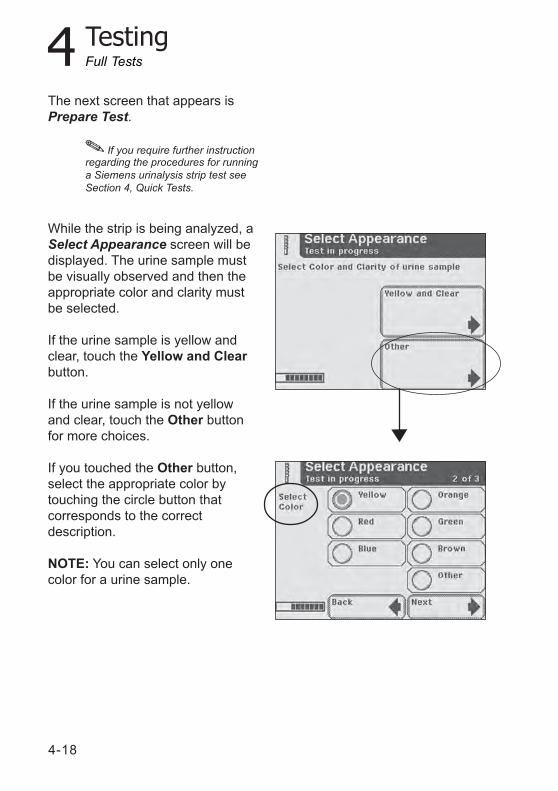
The next screen that appears isPrepare Test.
While the strip is being analyzed, aSelect Appearance screen will bedisplayed. The urine sample mustbe visually observed and then theappropriate color and clarity mustbe selected.
If the urine sample is yellow andclear, touch the Yellow and Clearbutton.
If the urine sample is not yellowand clear, touch the Other buttonfor more choices.
If you touched the Other button,select the appropriate color bytouching the circle button thatcorresponds to the correctdescription.
NOTE: You can select only onecolor for a urine sample.
If you require further instructionregarding the procedures for runninga Siemens urinalysis strip test seeSection 4, Quick Tests.
Full Tests
4 Testing
4-19
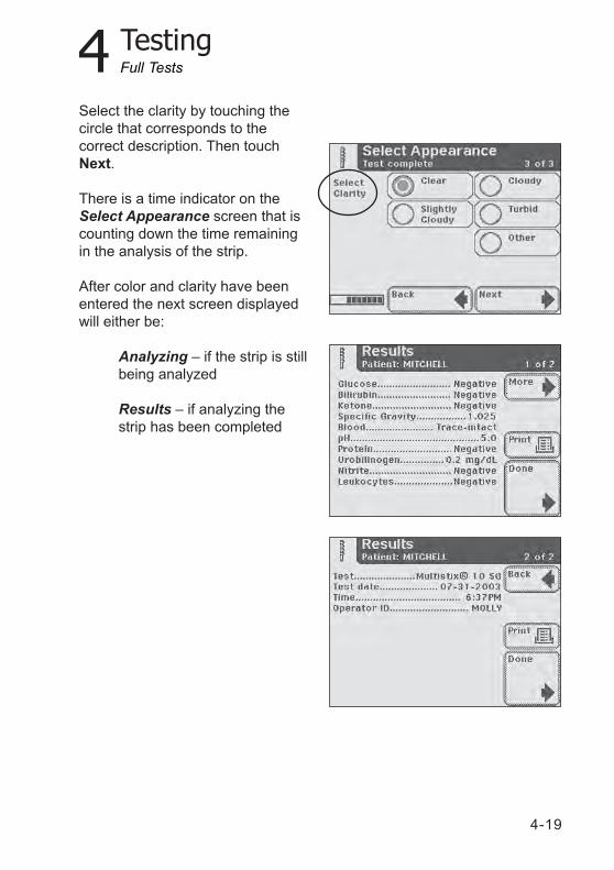
Select the clarity by touching thecircle that corresponds to thecorrect description. Then touchNext.
There is a time indicator on theSelect Appearance screen that iscounting down the time remainingin the analysis of the strip.
After color and clarity have beenentered the next screen displayedwill either be:
Analyzing – if the strip is stillbeing analyzed
Results – if analyzing thestrip has been completed
Full Tests
4-20
4 Testing
Entering the Strip Lot Numberand Expiration Date
To enter strip lot information for asecond strip test, perform thefollowing steps:1. At the Select screen, touch Strip
Test.The Strip screen displays.
2. To use the last strip number andbegin the test, touch Use LastLot.To enter new strip data, touchEnter new lot and expiration.The Strip Lot screen displays.
3. Enter the strip lot number.Use the alpha keyboard to entertext.To enter numeric text, touch 123.
4. Select Enter.The Strip Expiration screendisplays.
5. Use the arrow keys to indicatethe strip expiration date.
6. Touch Enter.The Prepare Test screendisplays.
7. Touch Start.See above.
Full Tests
4 Testing
4-21
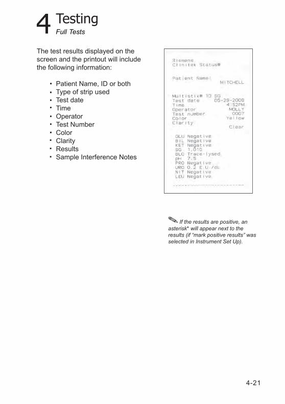
If the results are positive, anasterisk* will appear next to theresults (if “mark positive results” wasselected in Instrument Set Up).
The test results displayed on thescreen and the printout will includethe following information:
Patient Name, ID or bothType of strip usedTest dateTimeOperatorTest NumberColorClarityResultsSample Interference Notes
Full Tests
4-22
4 Testing
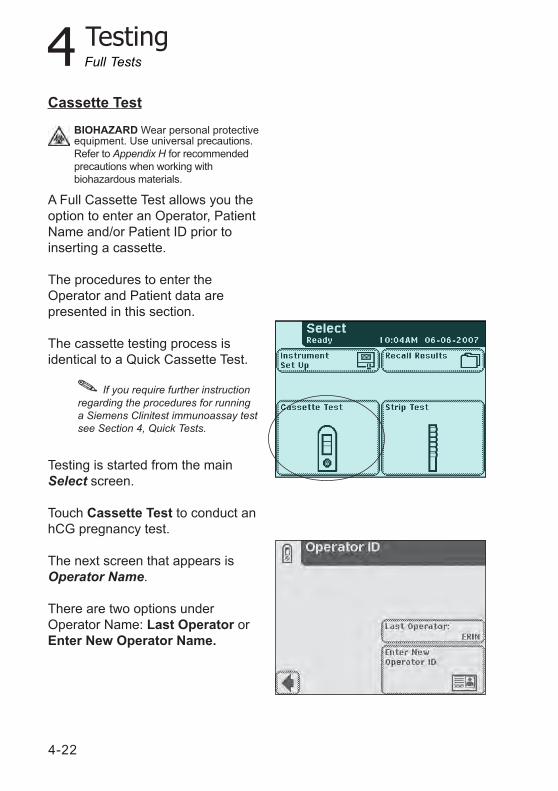
Cassette Test
A Full Cassette Test allows you theoption to enter an Operator, PatientName and/or Patient ID prior toinserting a cassette.
The procedures to enter theOperator and Patient data arepresented in this section.
The cassette testing process isidentical to a Quick Cassette Test.
If you require further instructionregarding the procedures for runninga Siemens Clinitest immunoassay testsee Section 4, Quick Tests.
Testing is started from the mainSelect screen.
Touch Cassette Test to conduct anhCG pregnancy test.
The next screen that appears isOperator Name.
There are two options underOperator Name: Last Operator orEnter New Operator Name.
Full Tests
BIOHAZARD Wear personal protectiveequipment. Use universal precautions.Refer to Appendix H for recommendedprecautions when working withbiohazardous materials.
4 Testing
4-23
The next screen displayed isPatient Information.
There are two options underPatient Information: Recall Patientor Enter New Patient.
Option 2: Enter New OperatorNameIn order to enter the information fora new operator, touch Enter NewOperator Name button. The nextscreen that is displayed is EnterOperator Name.
Use the keyboards to enterOperator Name using a maximumof 13 characters. Touch Enterwhen you have finished enteringthe name and to move to the nextscreen.
Full Tests
If you require further instructionregarding keyboard usage seeSection 2, Interacting with the TouchScreen.
Option 1: Last OperatorIf this option is enabled, the lastoperator that entered his/her Namewill be displayed on the screen inthe lower right side of the box. Ifyou are this operator, then touch theLast Operator button to proceed.
4-24
4 Testing
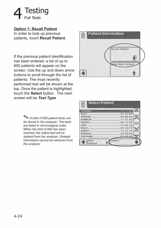
Option 1: Recall PatientIn order to look up previouspatients, touch Recall Patient.
If the previous patient identificationhas been entered, a list of up to950 patients will appear on thescreen. Use the up and down arrowbuttons to scroll through the list ofpatients. The most recentlyperformed test will be shown at thetop. Once the patient is highlighted,touch the Select button. The nextscreen will be Test Type.
A total of 950 patient tests canbe stored in the analyzer. The testsare listed in chronological order.When the limit of 950 has beenreached, the oldest test will bedeleted from the analyzer. Deletedinformation cannot be retrieved fromthe analyzer.
Full Tests
4 Testing
4-25
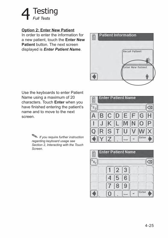
Option 2: Enter New PatientIn order to enter the information fora new patient, touch the Enter NewPatient button. The next screendisplayed is Enter Patient Name.
Use the keyboards to enter PatientName using a maximum of 20characters. Touch Enter when youhave finished entering the patient’sname and to move to the nextscreen.
Full Tests
If you require further instructionregarding keyboard usage seeSection 2, Interacting with the TouchScreen.
4-26
4 Testing
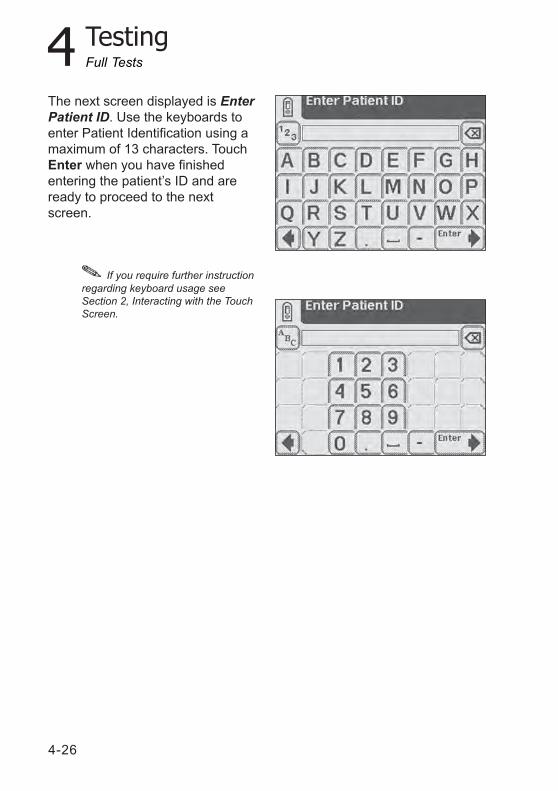
The next screen displayed is EnterPatient ID. Use the keyboards toenter Patient Identification using amaximum of 13 characters. TouchEnter when you have finishedentering the patient’s ID and areready to proceed to the nextscreen.
Full Tests
If you require further instructionregarding keyboard usage seeSection 2, Interacting with the TouchScreen.
4 Testing
4-27
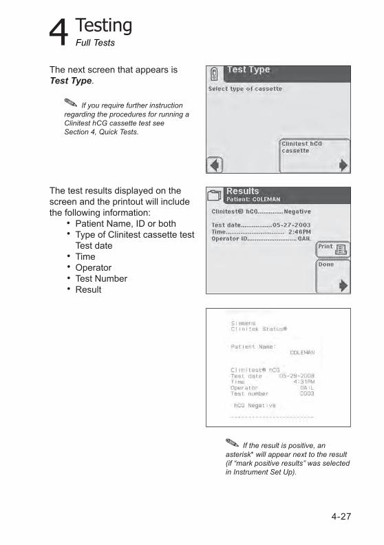
The next screen that appears isTest Type.
The test results displayed on thescreen and the printout will includethe following information:
Patient Name, ID or bothType of Clinitest cassette testTest dateTimeOperatorTest NumberResult
If the result is positive, anasterisk* will appear next to the result(if “mark positive results” was selectedin Instrument Set Up).
Full Tests
If you require further instructionregarding the procedures for running aClinitest hCG cassette test seeSection 4, Quick Tests.

4-28
5-1
5 Instrument Set Up
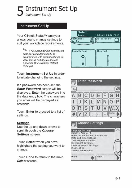
Your Clinitek Status®+ analyzerallows you to change settings tosuit your workplace requirements.
Touch Instrument Set Up in orderto initiate changing the settings.
If a password has been set, theEnter Password screen will bedisplayed. Enter the password intothe data entry box. The charactersyou enter will be displayed asasterisks.
Touch Enter to proceed to a list ofsettings.
SettingsUse the up and down arrows toscroll through the ChooseSettings screen.
Touch Select when you havehighlighted the setting you want tochange.
Touch Done to return to the mainSelect screen.
If no customizing is desired, theanalyzer will automatically beprogrammed with default settings (toview default settings please seeAppendix D: Instrument DefaultSettings).
Instrument Set Up
Instrument Set Up
5-2
5 Instrument Set Up
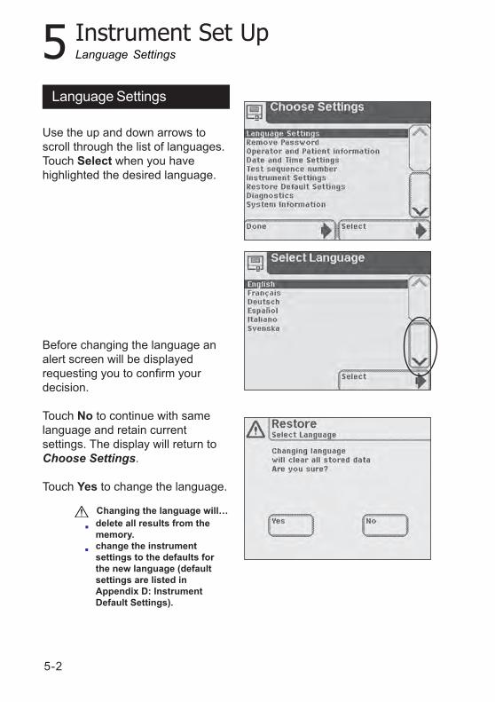
Use the up and down arrows toscroll through the list of languages.Touch Select when you havehighlighted the desired language.
Before changing the language analert screen will be displayedrequesting you to confirm yourdecision.
Touch No to continue with samelanguage and retain currentsettings. The display will return toChoose Settings.
Touch Yes to change the language.
Language Settings
Changing the language will…delete all results from thememory.change the instrumentsettings to the defaults forthe new language (defaultsettings are listed inAppendix D: InstrumentDefault Settings).
Language Settings
5-3
5 Instrument Set Up
Password
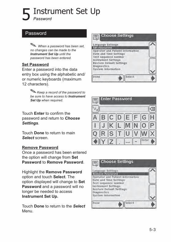
When a password has been set,no changes can be made to theInstrument Set Up until thepassword has been entered.
Set PasswordEnter a password into the dataentry box using the alphabetic and/or numeric keyboards (maximum12 characters).
Touch Enter to confirm thepassword and return to ChooseSettings.
Touch Done to return to mainSelect screen.
Remove PasswordOnce a password has been enteredthe option will change from SetPassword to Remove Password.
Highlight the Remove Passwordoption and touch Select. Theoption displayed will change to SetPassword and a password will nolonger be needed to accessInstrument Set Up.
Touch Done to return to the SelectMenu.
Keep a record of the password tobe sure to have access to InstrumentSet Up when required.
Password
5-4
5 Instrument Set Up
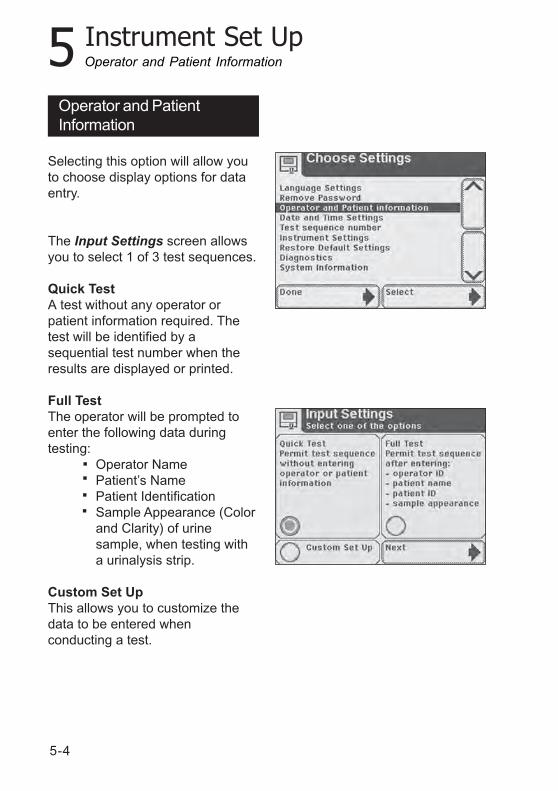
Operator and PatientInformation
Selecting this option will allow youto choose display options for dataentry.
The Input Settings screen allowsyou to select 1 of 3 test sequences.
Quick TestA test without any operator orpatient information required. Thetest will be identified by asequential test number when theresults are displayed or printed.
Full TestThe operator will be prompted toenter the following data duringtesting:
Operator NamePatient’s NamePatient IdentificationSample Appearance (Colorand Clarity) of urinesample, when testing witha urinalysis strip.
Custom Set UpThis allows you to customize thedata to be entered whenconducting a test.
Operator and Patient Information
5-5
5 Instrument Set Up
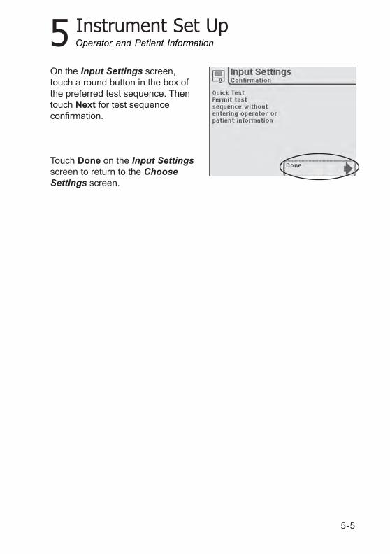
On the Input Settings screen,touch a round button in the box ofthe preferred test sequence. Thentouch Next for test sequenceconfirmation.
Touch Done on the Input Settingsscreen to return to the ChooseSettings screen.
Operator and Patient Information
5-6
5 Instrument Set Up
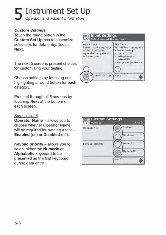
Custom SettingsTouch the round button in theCustom Set Up box to customizeselections for data entry. TouchNext.
The next 5 screens present choicesfor customizing your testing.
Choose settings by touching andhighlighting a round button for eachcategory.
Proceed through all 5 screens bytouching Next at the bottom ofeach screen.
Screen 1 of 5Operator Name – allows you tochoose whether Operator Namewill be required for running a test –Enabled (on) or Disabled (off).
Keypad priority – allows you toselect either the Numeric orAlphabetic keyboard to bepresented as the first keyboardduring data entry.
Operator and Patient Information
5-7
5 Instrument Set Up
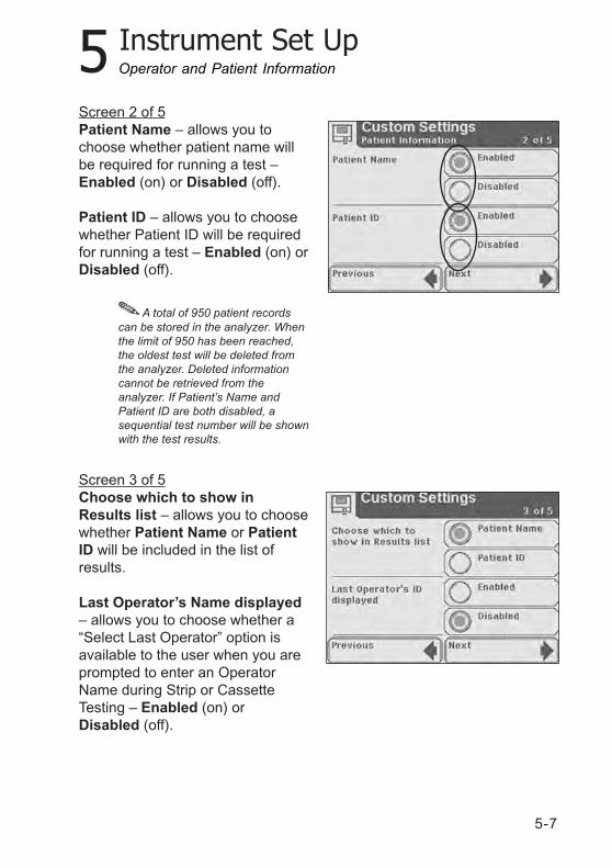
Screen 2 of 5Patient Name – allows you tochoose whether patient name willbe required for running a test –Enabled (on) or Disabled (off).
Patient ID – allows you to choosewhether Patient ID will be requiredfor running a test – Enabled (on) orDisabled (off).
Screen 3 of 5Choose which to show inResults list – allows you to choosewhether Patient Name or PatientID will be included in the list ofresults.
Last Operator’s Name displayed– allows you to choose whether a“Select Last Operator” option isavailable to the user when you areprompted to enter an OperatorName during Strip or CassetteTesting – Enabled (on) orDisabled (off).
Operator and Patient Information
A total of 950 patient recordscan be stored in the analyzer. Whenthe limit of 950 has been reached,the oldest test will be deleted fromthe analyzer. Deleted informationcannot be retrieved from theanalyzer. If Patient’s Name andPatient ID are both disabled, asequential test number will be shownwith the test results.
5-8
5 Instrument Set Up
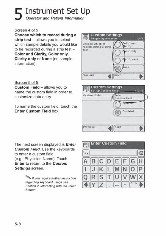
Screen 4 of 5Choose which to record during astrip test – allows you to selectwhich sample details you would liketo be recorded during a strip test –Color and Clarity, Color only,Clarity only or None (no sampleinformation).
Screen 5 of 5Custom Field – allows you toname the custom field in order tocustomize data entry.
To name the custom field, touch theEnter Custom Field box.
The next screen displayed is EnterCustom Field. Use the keyboardsto enter a custom field(e.g., Physician Name). TouchEnter to return to the CustomSettings screen.
Operator and Patient Information
If you require further instructionregarding keyboard usage seeSection 2, Interacting with the TouchScreen.
5-9
5 Instrument Set Up
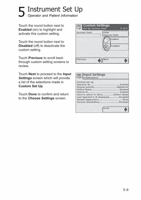
Touch the round button next toEnabled (on) to highlight andactivate this custom setting.
Touch the round button next toDisabled (off) to deactivate thecustom setting.
Touch Previous to scroll backthrough custom setting screens toreview.
Touch Next to proceed to the InputSettings screen which will providea list of the selections made inCustom Set Up.
Touch Done to confirm and returnto the Choose Settings screen.
Operator and Patient Information
5-10
5 Instrument Set Up
Managing Urine Colors
The following sections describe howto customize and set urine colorchoices and urine clarity for Siemensstrip tests. When you print patienttest results, you can include urinecolor, clarity, or color and clarity inthe printout. Urine color and clarityare optional; you can choose not toprint these parameters. Urine colorand clarity are available only in FullTest or Custom mode.
Setting and Customizing UrineColors
You can choose from one of 10instrument-provided colors and addup to 4 customized colors to patienttest results.To include instrument-providedcolors, perform the following steps:1. At the Select screen, touch
Instrument Set Up.The Choose Settings screendisplays.
2. Use the arrow keys to selectOperator and Patientinformation.
3. Touch Select.The Input Settings screendisplays.
4. Touch Custom Set Up.5. Touch Next.
The Custom Settings-Operatorscreen 1 of 5 displays.
6. Touch Next 3 times.The Custom Settings-SampleAppearance screen 4 of5 displays.
Operator and Patient Information
5-11
5 Instrument Set Up
7. Touch Edit colors.The Sample Appearance-Selectcolors screen 1 of 3 displays.
8. To choose colors, touch thebutton for the color you want.To remove a selected color,touch that color button again.
9. Touch Next.The Sample Appearance-Selectcolors screen 2 of 3 displays.
10. To choose colors, touch thebutton for the color you want.
11. Touch Next.The Sample Appearance-Selectcolors screen 3 of 3 displays.
12. Touch Next 3 times.The Input Settings-Confirmationscreen displays.
13. Touch Done twice to return tothe Select screen.
Adding Customized Colors
To enter up to 4 custom colors,perform the following steps:1. At the Sample Appearance-
Select colors screen 3 of 3,touch Enter custom color 1(2, 3, or 4) corresponding toeach custom color.
2. Enter the custom color.Use the alpha keyboard toenter text.To enter numeric text, touch123.
NOTE: The maximum number ofcharacters for each color is 10.
Operator and Patient Information
5-12
5 Instrument Set Up
3. Touch Enter.The Sample Appearance-Selectcolors screen 3 of 3 displays.
CAUTIONDo not edit a custom color thatalready exists because doing sodeletes all patient records stored onthe system.
If a custom color exists, theSample Appearance screendisplays.Touch Yes, to edit that customcolor and delete all records.Touch No, to return to theSample Appearance SelectColors screen 3 of 3.
4. Touch Next 3 times.The Input Settings-Confirmationscreen displays.
5. Touch Done twice to return tothe Select screen.
Managing Strip Lot Number andExpiration Date
You can enter the strip lot numberand expiration date and associatethis information with each patientrecord. Once entered, theinformation is retained for the nexttest, or you can enter a new lotnumber and expiration date.You can set the instrument toprompt for new strip information oruse the information from the laststrip before each patient test.
Operator and Patient Information
5-13
5 Instrument Set Up
Setting Strip Information Prompt
To set the prompt for stripinformation, perform the followingsteps:1. At the Select screen, touch
Instrument Set Up.The Choose Settings screendisplays.
2. Use the arrow keys to selectInstrument Settings.
3. Touch Enter.The Instrument Settings screendisplays.
4. Use the arrow keys to selectUrinalysis Test Settings.
5. Touch Select.The Urinalysis Test Settingsscreen displays.
6. Touch Next.The Urinalysis Test screendisplays.
7. To prompt for strip informationbefore each test, touchEnabled.To bypass a prompt to enterstrip information before eachtest, touch Disabled.
8. Touch Done 3 times to return tothe Select screen.
Intrument Settings
5-14
5 Instrument Set Up
Date and Time Settings
Date and Time Settings
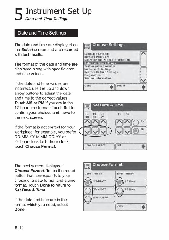
The date and time are displayed onthe Select screen and are recordedwith test results.
The format of the date and time aredisplayed along with specific dateand time values.
If the date and time values areincorrect, use the up and downarrow buttons to adjust the dateand time to the correct values.Touch AM or PM if you are in the12-hour time format. Touch Set toconfirm your choices and move tothe next screen.
If the format is not correct for yourworkplace, for example, you preferDD-MM-YY to MM-DD-YY or24-hour clock to 12-hour clock,touch Choose Format.
The next screen displayed isChoose Format. Touch the roundbutton that corresponds to yourchoice of a date format and a timeformat. Touch Done to return toSet Date & Time.
If the date and time are in theformat which you need, selectDone.
5-15
5 Instrument Set Up
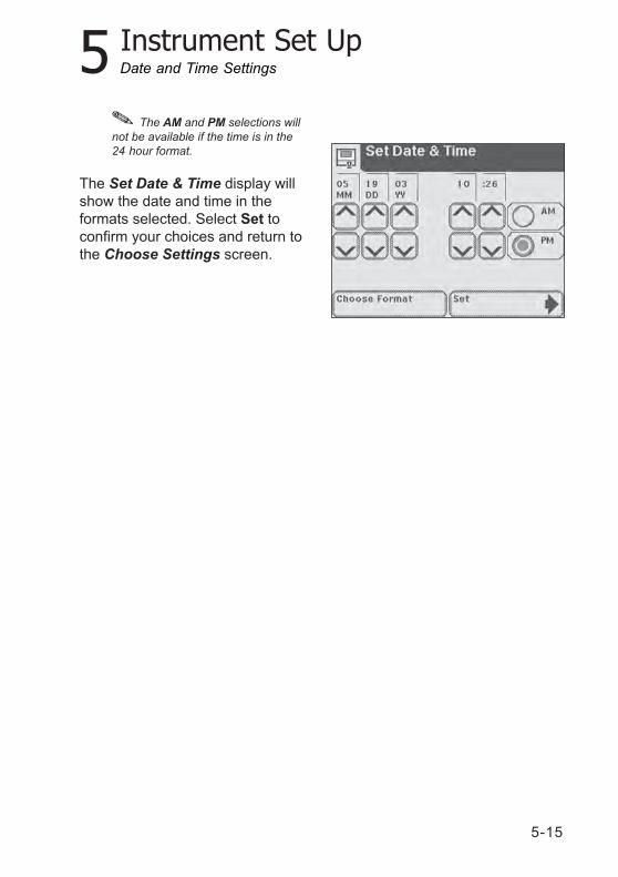
The Set Date & Time display willshow the date and time in theformats selected. Select Set toconfirm your choices and return tothe Choose Settings screen.
The AM and PM selections willnot be available if the time is in the24 hour format.
Date and Time Settings
5-16
5 Instrument Set Up
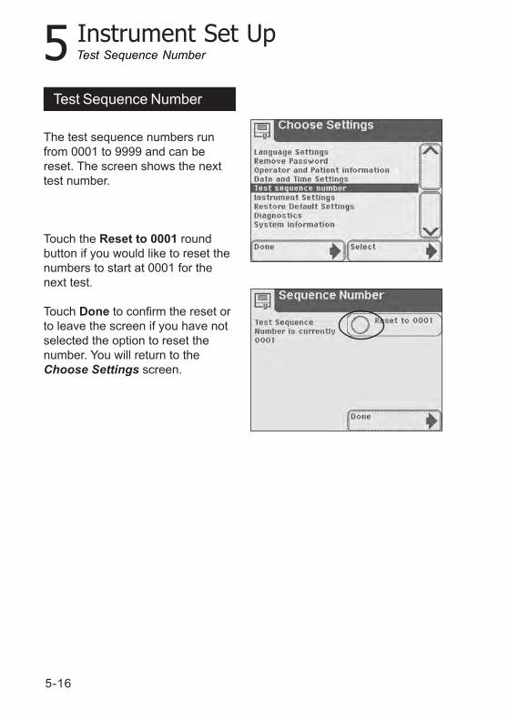
The test sequence numbers runfrom 0001 to 9999 and can bereset. The screen shows the nexttest number.
Touch the Reset to 0001 roundbutton if you would like to reset thenumbers to start at 0001 for thenext test.
Touch Done to confirm the reset orto leave the screen if you have notselected the option to reset thenumber. You will return to theChoose Settings screen.
Test Sequence Number
Test Sequence Number
5-17
5 Instrument Set Up
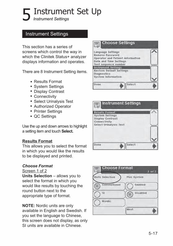
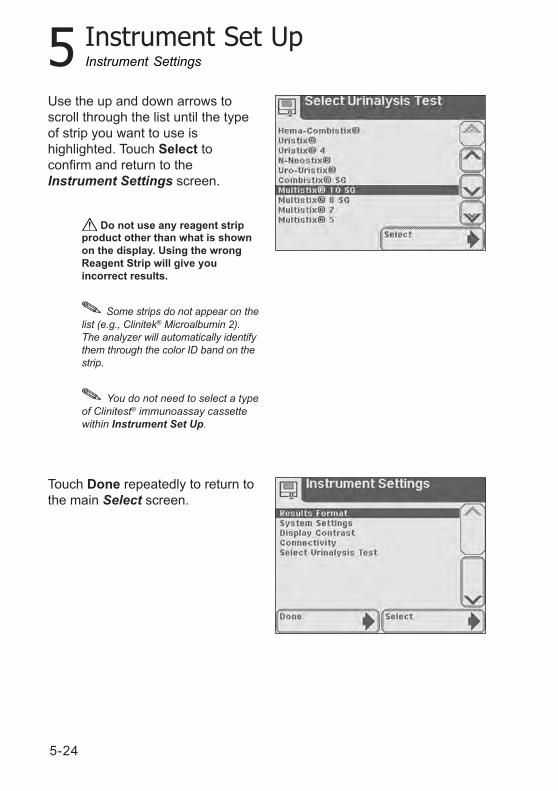
This section has a series ofscreens which control the way inwhich the Clinitek Status+ analyzerdisplays information and operates.
There are 8 Instrument Setting items.
Results FormatSystem SettingsDisplay ContrastConnectivitySelect Urinalysis TestAuthorized OperatorPrinter SettingsQC Settings
Use the up and down arrows to highlighta setting item and touch Select.
Results FormatThis allows you to select the formatin which you would like the resultsto be displayed and printed.
Choose FormatScreen 1 of 2Units Selection – allows you toselect the format in which youwould like results by touching theround button next to theappropriate type of format.
NOTE: Nordic units are onlyavailable in English and Swedish. Ifyou set the language to Chinese,this screen does not display, as onlySI units are available in Chinese.
Instrument Settings
Instrument Settings
5-18
5 Instrument Set Up
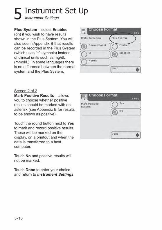
Plus System – select Enabled(on) if you wish to have resultsshown in the Plus System. You willalso see in Appendix B that resultscan be recorded in the Plus System(which uses “+” symbols) insteadof clinical units such as mg/dL(mmol/L). In some languages thereis no difference between the normalsystem and the Plus System.
Screen 2 of 2Mark Positive Results – allowsyou to choose whether positiveresults should be marked with anasterisk (see Appendix B for resultsto be shown as positive).
Touch the round button next to Yesto mark and record positive results.These will be marked on thedisplay, on a printout and when thedata is transferred to a hostcomputer.
Touch No and positive results willnot be marked.
Touch Done to enter your choiceand return to Instrument Settings.
Instrument Settings
5-19
5 Instrument Set Up
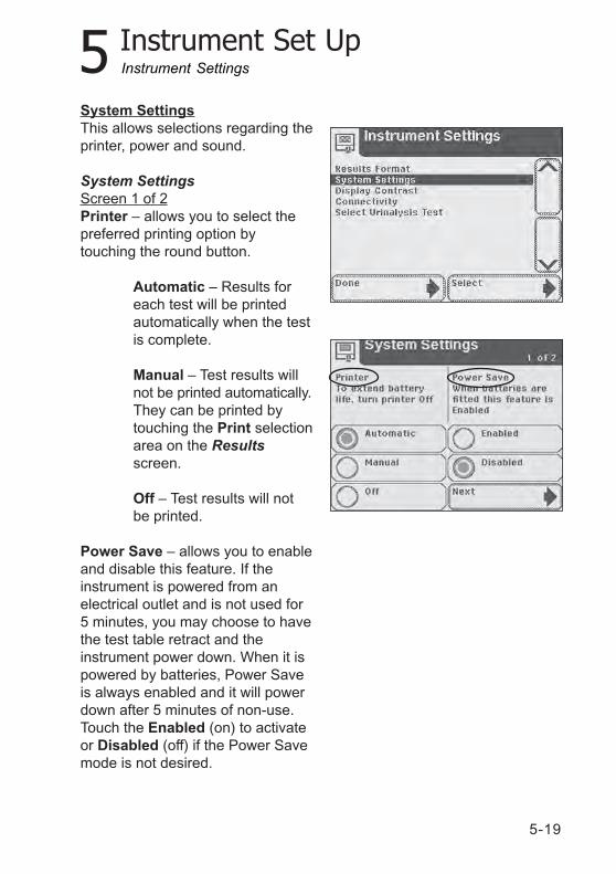
System SettingsThis allows selections regarding theprinter, power and sound.
System SettingsScreen 1 of 2Printer – allows you to select thepreferred printing option bytouching the round button.
Automatic – Results foreach test will be printedautomatically when the testis complete.
Manual – Test results willnot be printed automatically.They can be printed bytouching the Print selectionarea on the Resultsscreen.
Off – Test results will notbe printed.
Power Save – allows you to enableand disable this feature. If theinstrument is powered from anelectrical outlet and is not used for5 minutes, you may choose to havethe test table retract and theinstrument power down. When it ispowered by batteries, Power Saveis always enabled and it will powerdown after 5 minutes of non-use.Touch the Enabled (on) to activateor Disabled (off) if the Power Savemode is not desired.
Instrument Settings
5-20
5 Instrument Set Up
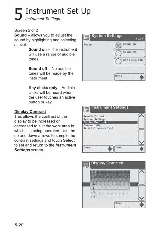
Screen 2 of 2Sound – allows you to adjust thesound by highlighting and selectinga level.
Sound on – The instrumentwill use a range of audibletones.
Sound off – No audibletones will be made by theinstrument.
Key clicks only – Audibleclicks will be heard whenthe user touches an activebutton or key.
Display ContrastThis allows the contrast of thedisplay to be increased ordecreased to suit the work area inwhich it is being operated. Use theup and down arrows to sample thecontrast settings and touch Selectto set and return to the InstrumentSettings screen.
Instrument Settings
5-21
5 Instrument Set Up
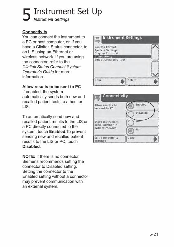
ConnectivityYou can connect the instrument toa PC or host computer, or, if youhave a Clinitek Status connector, toan LIS using an Ethernet orwireless network. If you are usingthe connector, refer to theClinitek Status Connect SystemOperator's Guide for moreinformation.
Allow results to be sent to PCIf enabled, the systemautomatically sends both new andrecalled patient tests to a host orLIS.
To automatically send new andrecalled patient results to the LIS ora PC directly connected to thesystem, touch Enabled.To preventsending new and recalled patientresults to the LIS or PC, touchDisabled.
NOTE: If there is no connector,Siemens recommends setting theconnector to Disabled setting.Setting the connector to theEnabled setting without a connectormay prevent communication withan external system.
Instrument Settings
5-22
5 Instrument Set Up
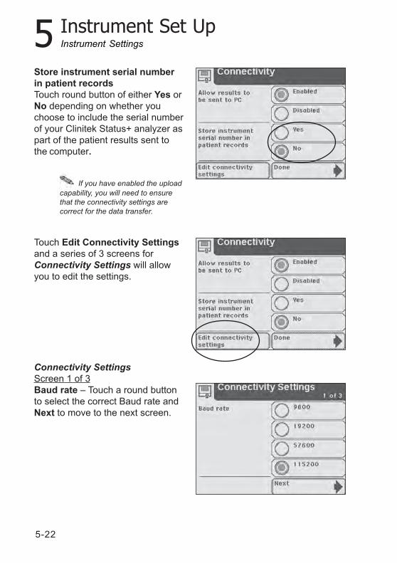
Store instrument serial numberin patient recordsTouch round button of either Yes orNo depending on whether youchoose to include the serial numberof your Clinitek Status+ analyzer aspart of the patient results sent tothe computer.
Touch Edit Connectivity Settingsand a series of 3 screens forConnectivity Settings will allowyou to edit the settings.
Connectivity SettingsScreen 1 of 3Baud rate – Touch a round buttonto select the correct Baud rate andNext to move to the next screen.
If you have enabled the uploadcapability, you will need to ensurethat the connectivity settings arecorrect for the data transfer.
Instrument Settings
5-23
5 Instrument Set Up
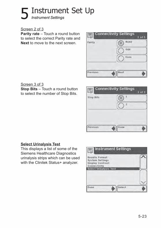
Screen 2 of 3Parity rate – Touch a round buttonto select the correct Parity rate andNext to move to the next screen.
Screen 3 of 3Stop Bits – Touch a round buttonto select the number of Stop Bits.
Select Urinalysis TestThis displays a list of some of theSiemens Healthcare Diagnosticsurinalysis strips which can be usedwith the Clinitek Status+ analyzer.
Instrument Settings
5-24
5 Instrument Set Up
Use the up and down arrows toscroll through the list until the typeof strip you want to use ishighlighted. Touch Select toconfirm and return to theInstrument Settings screen.
Touch Done repeatedly to return tothe main Select screen.
Do not use any reagent stripproduct other than what is shownon the display. Using the wrongReagent Strip will give youincorrect results.
Some strips do not appear on thelist (e.g., Clinitek® Microalbumin 2).The analyzer will automatically identifythem through the color ID band on thestrip.
You do not need to select a typeof Clinitest® immunoassay cassettewithin Instrument Set Up.
Instrument Settings
5-25
5 Instrument Set UpInstrument Settings
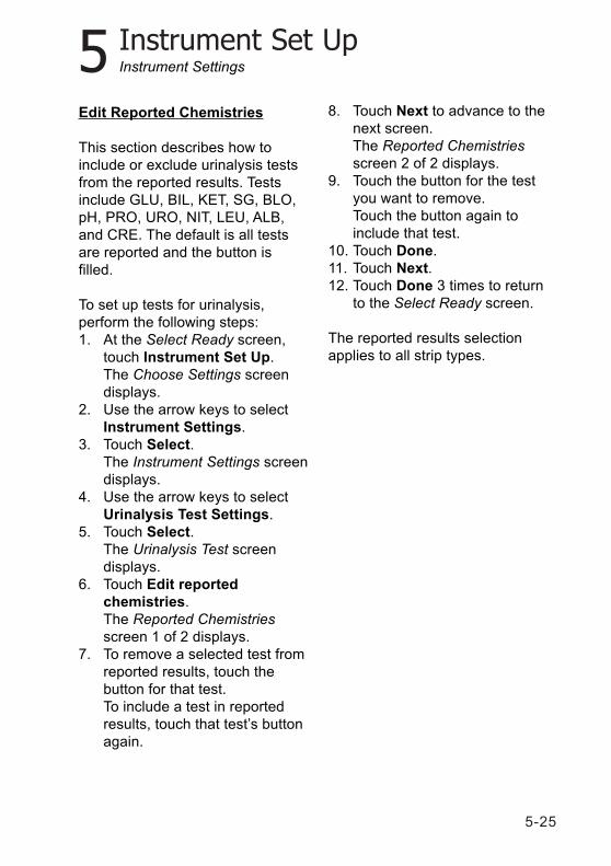
Edit Reported Chemistries
This section describes how toinclude or exclude urinalysis testsfrom the reported results. Testsinclude GLU, BIL, KET, SG, BLO,pH, PRO, URO, NIT, LEU, ALB,and CRE. The default is all testsare reported and the button isfilled.
To set up tests for urinalysis,perform the following steps:1. At the Select Ready screen,
touch Instrument Set Up.The Choose Settings screendisplays.
2. Use the arrow keys to selectInstrument Settings.
3. Touch Select.The Instrument Settings screendisplays.
4. Use the arrow keys to selectUrinalysis Test Settings.
5. Touch Select.The Urinalysis Test screendisplays.
6. Touch Edit reportedchemistries.The Reported Chemistriesscreen 1 of 2 displays.
7. To remove a selected test fromreported results, touch thebutton for that test.To include a test in reportedresults, touch that test’s buttonagain.
8. Touch Next to advance to thenext screen.The Reported Chemistriesscreen 2 of 2 displays.
9. Touch the button for the testyou want to remove.Touch the button again toinclude that test.
10. Touch Done.11. Touch Next.12. Touch Done 3 times to return
to the Select Ready screen.
The reported results selectionapplies to all strip types.
5-26
5 Instrument Set Up
Authorized Operator
This section describes how to set upuse of operator IDs and add, edit, ordelete the list of operator IDs. Whenenabled, the system permits onlyallowed operators to perform patienttests, QC tests (when using theconnector), recall results, or modifysystem settings. Operators gainaccess by entering their ID.
The Clinitek Status+ analyzerstores 700 operators.
NOTE: The Operator ID is neverprinted or displayed with patientresults. If you wish to associate theOperator’s Name with patientresults, enable Operator Name inCustom Settings-Operator screen1 of 5.
CAUTIONOnce the Operator ID and OperatorName settings are made, do notchange the Operator ID setting.If you change the OperatorID setting, all patient results areerased.
Setting Operator IDs
To set up operator IDs, perform thefollowing steps:1. At the Select Ready screen,
touch Instrument Set Up.The Choose Settings screendisplays.
Instrument Settings
2. Use the arrow keys to selectInstrument Settings.
3. Touch Select.The Instrument Settings screendisplays.
5-27
5 Instrument Set Up
4. Use the arrow keys to selectAuthorized Operator.
5. Touch Select.The Authorized operator screendisplays.
6. To permit access only byauthorized operators, touchEnabled.To allow all operators access tothe system, touch Disabled.
7. If you selected Enabled, seeAdding Operator IDs below toadd at least one operator.If you selected Disabled, touchDone 3 times to return to theSelect Ready screen.
CAUTIONIf the instrument uses the operatorlist sent by the LIS, do notpower down the system. If theconnector loses power, theoperator names are erased.
NOTE: The operator list sent by theLIS overwrites an operator listentered via the analyzer.
Adding Operator IDs
To add operator IDs, perform thefollowing steps:1. At the Authorized operator
screen, touch Add operator.2. Enter the new Operator ID.
Use the alpha keyboard to entertext.To enter numeric text, touch 123.
Instrument Settings
3. Touch Enter.The Authorized Operator screendisplays indicating the OperatorID and which functions theoperator can perform.
4. To edit this Operator ID, touchEdit.
5-28
5 Instrument Set Up
5. To edit which functions thisOperator ID can access, touchEdit.The Authorized Operator-Operator access screen 1 of 2displays.
6. To allow this operator to runpatient tests, touch Enabled.To prevent patient tests, touchDisabled.
7. To allow this operator to runQC tests, touch Enabled.To prevent QC tests, touchDisabled.
8. Touch Next.The Authorized Operator-Operator access screen 2 of2 displays.
9. To allow this operator to recallresults, touch elect Enabled.To prevent recall results, touchDisabled.
10. To allow this operator to set upthe instrument, touch Enabled.To prevent instrument setup,touch Disabled.
11. Touch Done twice.The Authorized Operator-Operators list screen displays.
12. Touch Exit.13. Touch Done 3 times to return
to the Select Ready screen.
Instrument Settings
Viewing, Editing, Printing, andDeleting Operator IDs
You can view, print, or delete theentire operator list or edit individualoperators.
NOTE: If you delete the entireoperator list, ensure thatauthorized operators is Disabled.See Setting Operator IDs above.
5-29
5 Instrument Set UpInstrument Settings
At the Authorized operator screen,perform the following steps:1. To delete the entire operators
list, touch Delete operators list.The Delete operators list cautionscreen displays.
2. To delete, touch Yes.To keep the operators list,touch No.If you selected No, theAuthorized operator screendisplays.If you selected Yes, go to Step 8.
3. To edit or view the operators list,touch View operators list.The Authorized Operator-Operators list screen displays.
4. Use the arrow keys to select theoperator you want to delete oredit.
5. To delete that operator, touchDelete entry.To edit or delete that operator,touch Select.The Authorized operator screendisplays.Refer to Adding Operator IDsabove, Step 6.
6. To print all operators, touchPrint.
NOTE: The system prints the first100 operators listed alphabetically.
7. To return to the Authorizedoperator screen, touch Exit.
8. Touch Done 3 times to return tothe Select Ready screen.
NOTE: Enabling the instrumentpassword restricts access toInstrument Setup to those whoknow the password. If bothOperator ID and password areenabled, the Operator ID haspriority.
5-30
5 Instrument Set Up
Printer Settings
This section describes how tocustomize the printed test results.
Customizing the Printout
You can customize the test resultsprintout by including or excluding:
Operator namePatient namePatient IDInstrument serial numberUrine colorUrine clarityUp to 2 header lines ofcustomized alphanumeric text
To customize the printout, performthe following steps:
1. At the Select Ready screen,touch Instrument Set Up.The Choose Settings screendisplays.
2. Use the arrow keys to selectInstrument Settings.
3. Touch Select.The Instrument Settings screendisplays.
4. Use the arrow keys to selectPrinter Settings.
5. Touch Select.The Printer Settings-Includedin print-out screen 1 of 4displays.
Instrument Settings
6. To select options, for exampleOperator Name, SerialNumber, Patient Name, orPatient ID to include in theprintout, touch the optionbutton.
5-31
5 Instrument Set Up
To remove a selected option,touch that option button again.
7. Touch Next.The Printer Settings-Included inprint-out screen 2 of 4 displays.
8. To select options, for example,Color, Clarity, or CustomInformation to include in theprintout, touch the option button.To remove a selected option,touch that option button again.
9. Select Next.The Printer Settings-Set UpCustom Header screen 3 of 4displays.
10. To include a custom header inthe printout, touch Enabled.To exclude a custom header,touch Disabled.
11. To edit or create line 1 of acustom header, touch EnterLine 1.The Custom Header screendisplays.
12. Enter custom header text.Use the alphabetic keyboard toenter text.To enter numeric text, touch 123.
13. Touch Enter.The Printer Settings-Set UpCustom Header screen 3 of 4displays.
14. To edit or create line 2 of acustom header, touch EnterLine 2.
NOTE: Each custom header lineaccepts up to 24 alphanumericcharacters.
Instrument Settings
5-32
5 Instrument Set Up
15. Touch Next.The Printer Settings screen 4of 4 displays.
16. To print to the internal printer,touch Internal printer.To print to an external printer,touch External printer.
17. If you selected Internal printer,to print sample interferencenotes, touch Enabled.To disable printing sampleinterference notes, touchDisabled.
NOTE: If you select Externalprinter, sample interference notesare automatically sent to theprinter.
18. Touch Done 3 times to returnto the Select Ready screen.
NOTE: To use an external printer,you must connect and enable theClinitek Status connector.
Quality Control
For QC instructions, refer to theClinitek Status Connect SystemOperator’s Guide.
Instrument Settings
5-33
5 Instrument Set Up
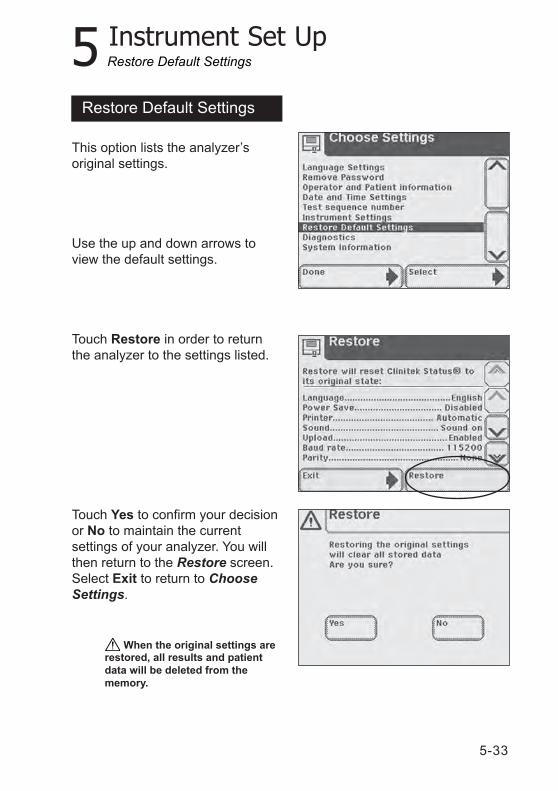
This option lists the analyzer’soriginal settings.
Use the up and down arrows toview the default settings.
Touch Restore in order to returnthe analyzer to the settings listed.
Touch Yes to confirm your decisionor No to maintain the currentsettings of your analyzer. You willthen return to the Restore screen.Select Exit to return to ChooseSettings.
Restore Default Settings
When the original settings arerestored, all results and patientdata will be deleted from thememory.
Restore Default Settings
5-34
5 Instrument Set Up
Diagnostics
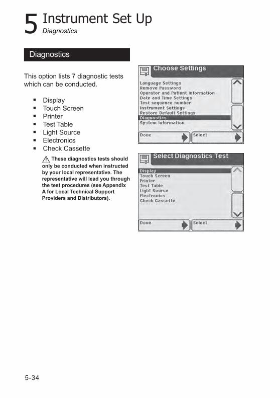
These diagnostics tests shouldonly be conducted when instructedby your local representative. Therepresentative will lead you throughthe test procedures (see AppendixA for Local Technical SupportProviders and Distributors).
Diagnostics
This option lists 7 diagnostic testswhich can be conducted.
DisplayTouch ScreenPrinterTest TableLight SourceElectronicsCheck Cassette
5-35
5 Instrument Set UpSample Notes
To include Sample InterferenceNotes, perform the following steps:
1. At the Select screen, touchInstrument Set Up.The Choose Settings screen displays.
2. Use the arrow keys to selectSample Notes.
3. Touch Select.The Notes Settings screen displays.
4. To enable Sample InterferenceNotes, touch Enabled.To disable Sample InterferenceNotes, touch Disabled.
5. Touch Done twice to return tothe Select screen.
Sample Interference Notes
5-36
5 Instrument Set Up
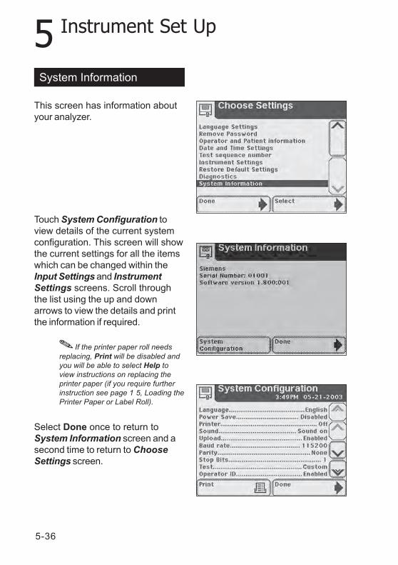
If the printer paper roll needsreplacing, Print will be disabled andyou will be able to select Help toview instructions on replacing theprinter paper (if you require furtherinstruction see page 1 5, Loading thePrinter Paper or Label Roll).
This screen has information aboutyour analyzer.
Touch System Configuration toview details of the current systemconfiguration. This screen will showthe current settings for all the itemswhich can be changed within theInput Settings and InstrumentSettings screens. Scroll throughthe list using the up and downarrows to view the details and printthe information if required.
Select Done once to return toSystem Information screen and asecond time to return to ChooseSettings screen.
System Information
5-37
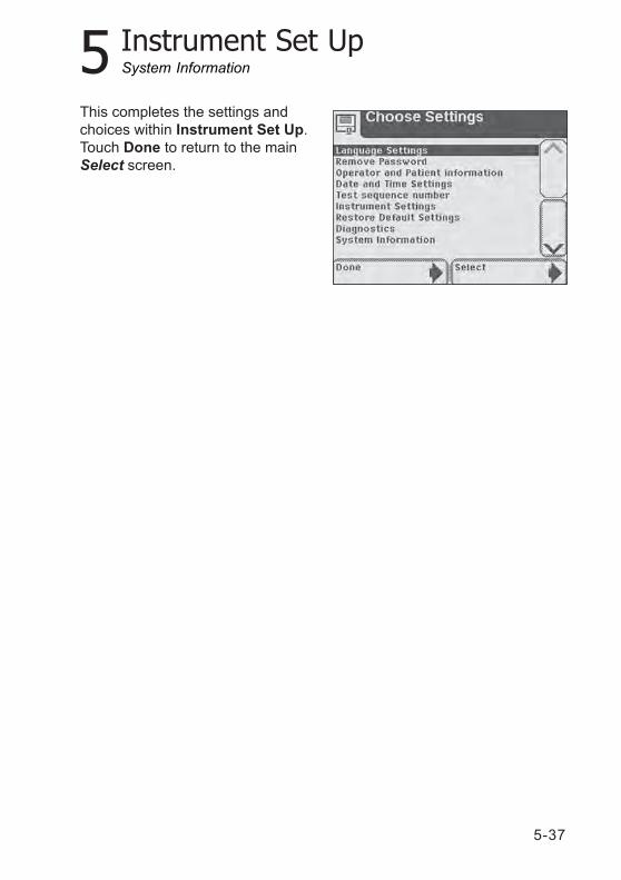
5 Instrument Set Up
This completes the settings andchoices within Instrument Set Up.Touch Done to return to the mainSelect screen.
System Information

5-38
6-1
6 Recall Results
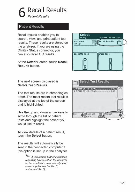
Recall results enables you tosearch, view, and print patient testresults. These results are stored onthe analyzer. If you are using theClinitek Status connector, youcan also recall QC results.
At the Select Screen, touch RecallResults button.
The next screen displayed isSelect Test Results.
The test results are in chronologicalorder. The most recent test result isdisplayed at the top of the screenand is highlighted.
Use the up and down arrow keys toscroll through the list of patienttests and highlight the patient youwould like to recall.
To view details of a patient result,touch the Select button.
The results will automatically besent to the connected computer ifthis option is set up in the analyzer.
Patient Results
Patient Results
If you require further instructionregarding how to set up the analyzerso the results are automatically sentto a computer see Section 5,Instrument Set Up.
6-2
6 Recall Results
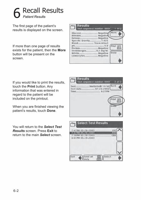
The first page of the patient’sresults is displayed on the screen.
If more than one page of resultsexists for the patient, then the Morebutton will be present on thescreen.
If you would like to print the results,touch the Print button. Anyinformation that was entered inregard to the patient will beincluded on the printout.
When you are finished viewing thepatient’s results, touch Done.
You will return to the Select TestResults screen. Press Exit toreturn to the main Select screen.
Patient Results
6-3
6 Recall Results
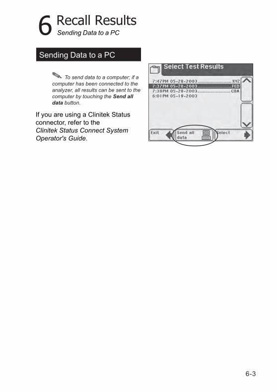
To send data to a computer; if acomputer has been connected to theanalyzer, all results can be sent to thecomputer by touching the Send alldata button.
Sending Data to a PC
Sending Data to a PC
If you are using a Clinitek Statusconnector, refer to theClinitek Status Connect SystemOperator's Guide.

6-4
7-1
7 Troubleshooting
General InformationYour Clinitek Status®+ analyzer willoperate properly if you follow thedirections for using and cleaningthe instrument.
Error MessagesError messages will be displayed tohelp you when the Clinitek Status+analyzer detects something whichneeds your attention. The format ofthis advisory information dependsupon the importance of theproblem and the mode in which theinstrument is being used.
Errors which Disable theInstrumentIf the error is one which preventsthe instrument from being used, allselection areas on the screen willbe disabled. Taking the correctiveaction shown will remove the erroralert screen and allow you to usethe instrument.
Other ErrorsThere are certain errors which needto be corrected to enable testing ofsamples but do not prevent otherinstrument functions from beingused. You will need to carry out thecorrective action to enable testing.
Advisory MessagesErrors of less importance will bepresented via a message on themain Select screen when thisscreen is next displayed. When youhave taken corrective action, themessage will be removed from thedisplay. If more than one of thisclass of error occurs, clearing onemessage will enable the next to bedisplayed in order of importance toa user.
Results AlertIf an error occurs during testing andthe test cannot continue because ofthe error, this will be presented viathe Results Alert screen. This willprovide details of the error andshow that the test has beencancelled. The test table will beextended so that the urinalysis stripor Clinitest® cassette can beremoved.
To correct an error, see the List ofErrors and Advisory Messages locatedat the end of this section.
7-2
7 Troubleshooting
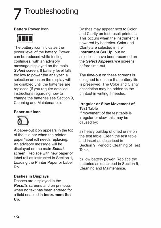
Battery Power Icon
The battery icon indicates thepower level of the battery. Powercan be reduced while testingcontinues, with an advisorymessage displayed on the mainSelect screen. If battery level fallstoo low to power the analyzer, allselection areas on the display willbe disabled until the batteries arereplaced (if you require detailedinstructions regarding how tochange the batteries see Section 9,Cleaning and Maintenance).
Paper-out Icon
A paper-out icon appears in the topof the title bar when the printerpaper/label roll needs replacing.An advisory message will bedisplayed on the main Selectscreen. Replace with new paper orlabel roll as instructed in Section 1,Loading the Printer Paper or LabelRoll.
Dashes in DisplaysDashes are displayed in theResults screens and on printoutswhen no text has been entered fora field enabled in Instrument SetUp.
Dashes may appear next to Colorand Clarity on test result printouts.This occurs when the instrument ispowered by batteries. Color andClarity are selected in theInstrument Set Up, but noselections have been recorded onthe Select Appearance screensbefore time-out.
The time-out on these screens isdesigned to ensure that battery lifeis preserved. The Color and Claritydescription may be added to theprintout in writing if needed.
Irregular or Slow Movement ofTest TableIf movement of the test table isirregular or slow, this may becaused by:
a) heavy buildup of dried urine onthe test table. Clean the test tableand insert as described inSection 9, Periodic Cleaning of TestTable.
b) low battery power. Replace thebatteries as described in Section 9,Cleaning and Maintenance.
7-3
7 Troubleshooting
Calling for AssistanceIf your Clinitek Status+ analyzer isdisplaying corrective actions for adetected problem, please carry outthe displayed instructions beforecalling for assistance. If this doesnot correct the problem or noinstructions are displayed, contactyour local technical supportprovider (for contact informationplease see Appendix A, LocalTechnical Support Providers andDistributors).
If you are calling for assistance witha displayed error, please have thefollowing items ready (this willassist your local representative todeal with your inquiry as quickly aspossible).
a) Error numberb) Completed Problem
Checklist (found at the endof this section).
For customer support, pleasecontact your local technical supportprovider or distributor (for contactinformation please see Appendix A,Local Technical Support Providersand Distributors).
WarrantyYour Clinitek Status+ analyzer hasa one-year warranty period. Thiswarranty is designed to protect youfrom the cost associated withrepairing systems that exhibitmalfunctions due to defects inmaterials and/or workmanshipduring the warranty period.
The warranty period commencesfrom the date that the instrument isreceived at your location. Use theWarranty Registration Cardprovided with the instrument toregister your warranty.
To obtain assistance during thewarranty period, please contactyour local technical supportprovider or distributor.
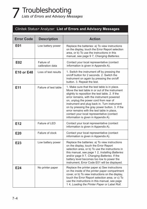
7-4
7 Troubleshooting
Error Code Description Action
E01 Replace the batteries: a) To view instructionson the display, touch the Error Report selectionarea, or b) To use the instructions in thismanual, see page 9 7, Changing Batteries.
Low battery power
Lists of Errors and Advisory Messages
List of Errors and Advisory Messages Clinitek Status+ Analyzer:
1. Switch the instrument off by pressing theon/off button for 2 seconds. 2. Switch theinstrument on again by pressing the on/offbutton. 3. Repeat the test.
Loss of test results
E11 1. Make sure that the test table is in place.Move the test table in or out of the instrumentslightly to reposition the test table. 2. If theerror remains, with the instrument poweredon, unplug the power cord from rear ofinstrument and plug back in. Turn instrumenton by pressing the gray power button. 3. If theerror remains with the test table in place,contact your local representative (contactinformation is given in Appendix A).
Failure of test table
E10 or E48
E02 Contact your local representative (contactinformation is given in Appendix A).
Failure ofcalibration data
E23 Replace the batteries: a) To view instructionson the display, touch the Error Reportselection area, or b) To use the instructions inthis manual, see page 1 2, Installing Batteriesand/or page 9 7, Changing Batteries. If thebattery level becomes too low to power theinstrument, Error Code E01 will be displayed.
Low battery power
E24 Replace the printer paper a) See instructionson the inside of the printer paper compartmentcover, or b) To view instructions on the display,touch the Error Report selection area, or c) Touse the instructions in this manual, see page1 4, Loading the Printer Paper or Label Roll.
No printer paper
E12 Contact your local representative (contactinformation is given in Appendix A).
Failure of LED
E20 Contact your local representative (contactinformation is given in Appendix A).
Failure of clock
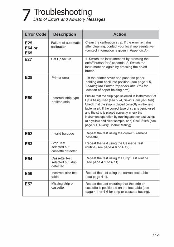
7-5
7 Troubleshooting
Error Code Description Action
Lists of Errors and Advisory Messages
E25,E64 orE65
Clean the calibration strip. If the error remainsafter cleaning, contact your local representative(contact information is given in Appendix A).
Failure of automaticcalibration
E27 1. Switch the instrument off by pressing theon/off button for 2 seconds. 2. Switch theinstrument on again by pressing the on/offbutton.
Set Up failure
E28 Lift the printer cover and push the paperholding arm back into position (see page 1 5,Loading the Printer Paper or Label Roll forlocation of paper holding arm).
Printer error
E50 Incorrect strip typeor tilted strip
E52 Repeat the test using the correct Siemenscassette.
Invalid barcode
E53 Repeat the test using the Cassette Testroutine (see page 4 6 or 4 19).
Strip Testselected butcassette detected
E54 Repeat the test using the Strip Test routine(see page 4 1 or 4 11).
Cassette Testselected but stripdetected
E56 Repeat the test using the correct test table(see page 4 1).
Incorrect size testtable
E57 Repeat the test ensuring that the strip orcassette is positioned on the test table (seepage 4 1 or 4 6 for strip or cassette testing).
Missing strip orcassette
Ensure that the strip type selected in Instrument SetUp is being used (see 5 24, Select Urinalysis Test).Check that the strip is placed correctly on the testtable insert. If the correct type of strip is being usedand the strip is placed correctly, check theinstrument operation by running another test using:a) a yellow and clear sample, or b) Chek Stix® (seepage 8 1, Quality Control Testing).
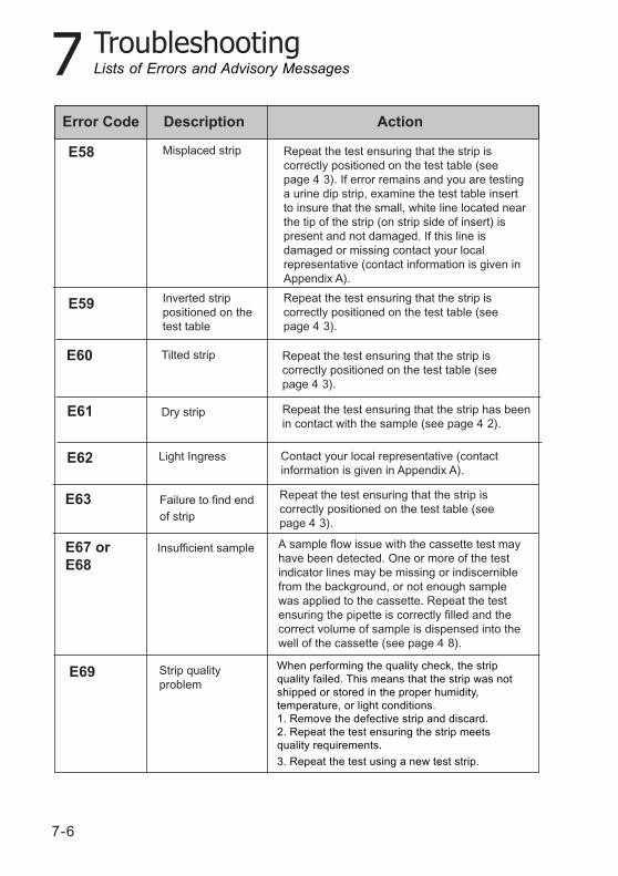
7-6
7 Troubleshooting
Error Code Description Action
E60
Lists of Errors and Advisory Messages
Repeat the test ensuring that the strip iscorrectly positioned on the test table (seepage 4 3).
Tilted strip
E61 Repeat the test ensuring that the strip has beenin contact with the sample (see page 4 2).
Dry strip
E63 Repeat the test ensuring that the strip iscorrectly positioned on the test table (seepage 4 3).
Failure to find endof strip
E67 orE68
A sample flow issue with the cassette test mayhave been detected. One or more of the testindicator lines may be missing or indiscerniblefrom the background, or not enough samplewas applied to the cassette. Repeat the testensuring the pipette is correctly filled and thecorrect volume of sample is dispensed into thewell of the cassette (see page 4 8).
Insufficient sample
E69 Strip qualityproblem
When performing the quality check, the stripquality failed. This means that the strip was notshipped or stored in the proper humidity,temperature, or light conditions.1. Remove the defective strip and discard.2. Repeat the test ensuring the strip meetsquality requirements.
3. Repeat the test using a new test strip.
E58 Repeat the test ensuring that the strip iscorrectly positioned on the test table (seepage 4 3). If error remains and you are testinga urine dip strip, examine the test table insertto insure that the small, white line located nearthe tip of the strip (on strip side of insert) ispresent and not damaged. If this line isdamaged or missing contact your localrepresentative (contact information is given inAppendix A).
Misplaced strip
E59 Repeat the test ensuring that the strip iscorrectly positioned on the test table (seepage 4 3).
Inverted strippositioned on thetest table
E62 Contact your local representative (contactinformation is given in Appendix A).
Light Ingress
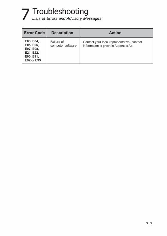
7-7
7 Troubleshooting
Error Code Description Action
E03, E04,E05, E06,E07, E08,E21, E22,E90, E91,E92 or E93
Contact your local representative (contactinformation is given in Appendix A).
Failure ofcomputer software
Lists of Errors and Advisory Messages
7-8
7 Troubleshooting
Serial Number ___________________________
Installation Date___________________________
1. Have you reviewed the error messages on pages 7-4to 7-7?
2. Please record any error messages that have beendisplayed:________________________________________________________________________________________________________________________________________________________________________________________________
3. Does the test table move out to the “load” positionwhen the analyzer is first turned on?
4. If Question #3 is NO –Is the power cord plugged into a liveelectrical outlet, into the transformer, andthen into the analyzer?If using batteries, are they fully charged andcorrectly placed in the analyzer?
5. Does the display show the Select screen or theResults screen as expected?
6. Does the test table move into and out of theanalyzer?
7. Does a quality control solution give the expectedresult?
YES NO
Problem Checklist
Problem ChecklistClinitek Status+ Analyzer:
7-9
7 Troubleshooting
8. Is the name of the Siemens Healthcare Diagnosticsurinalysis strip or Clinitest immunoassay cassetteshown on the display the same as the product beingused?
9. Does the display or printout show the correct testnames and expected results?
10. Is the white calibration bar on the test table dirty,scratched, or damaged?
11. Additional problem observations, please describe: ________________________________________________________________________________________________________________________________________________________________________________________________________________________________________________________________________________________________________________________________________________________________________________________________________________________________________________________________________________________________________________________________________________________________________________________________________________________________________________________________________________________________________________________________________________________________________________
YES NO
Problem Checklist

7-10
8-1
8 Quality Control Testing
If you are using a Clinitek Statusconnector, refer to theClinitek Status Connect SystemOperator's Guide.
Quality Control for UrinalysisStrip Testing
Test negative and positive controlswhenever a new bottle of reagentstrips is first opened.
Water should NOT be used as anegative control. Contact yourSiemens representative foradditional information on performingQC testing.
Quality Control for CassetteTesting
It is recommended that qualitycontrol specimens be used witheach new reagent box opened.
Water should NOT be used as anegative control. Contact yourSiemens representative foradditional information on performingQC testing.
Refer to the quality controlproduct insert for expected values foreach analyte.
hCG Please refer to theClinitest®
hCG cassette test packageinsert for the appropriate qualitycontrol material.
8 Quality Control Testing

8-2
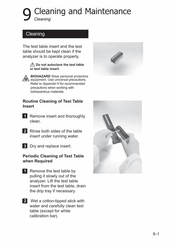
9-1
9 Cleaning and Maintenance
The test table insert and the testtable should be kept clean if theanalyzer is to operate properly.
Routine Cleaning of Test TableInsert
1 Remove insert and thoroughlyclean.
2 Rinse both sides of the tableinsert under running water.
3 Dry and replace insert.
Periodic Cleaning of Test Tablewhen Required
1 Remove the test table bypulling it slowly out of theanalyzer. Lift the test tableinsert from the test table, drainthe drip tray if necessary.
2 Wet a cotton-tipped stick withwater and carefully clean testtable (except for whitecalibration bar).
Do not autoclave the test tableor test table insert.
Cleaning
Cleaning
BIOHAZARD Wear personal protectiveequipment. Use universal precautions.Refer to Appendix H for recommendedprecautions when working withbiohazardous materials.
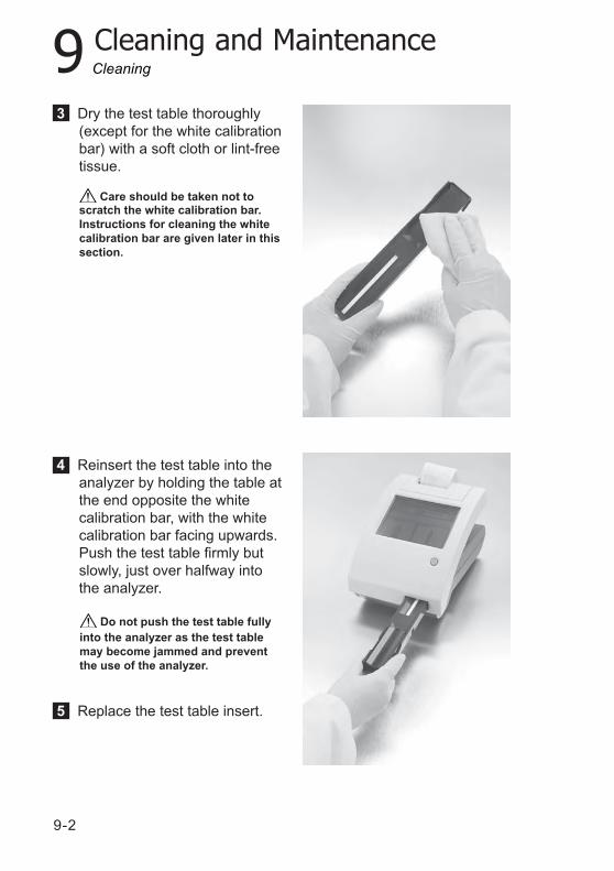
9-2
9 Cleaning and Maintenance
3 Dry the test table thoroughly(except for the white calibrationbar) with a soft cloth or lint-freetissue.
4 Reinsert the test table into theanalyzer by holding the table atthe end opposite the whitecalibration bar, with the whitecalibration bar facing upwards.Push the test table firmly butslowly, just over halfway intothe analyzer.
5 Replace the test table insert.
Cleaning
Care should be taken not toscratch the white calibration bar.Instructions for cleaning the whitecalibration bar are given later in thissection.
Do not push the test table fullyinto the analyzer as the test tablemay become jammed and preventthe use of the analyzer.
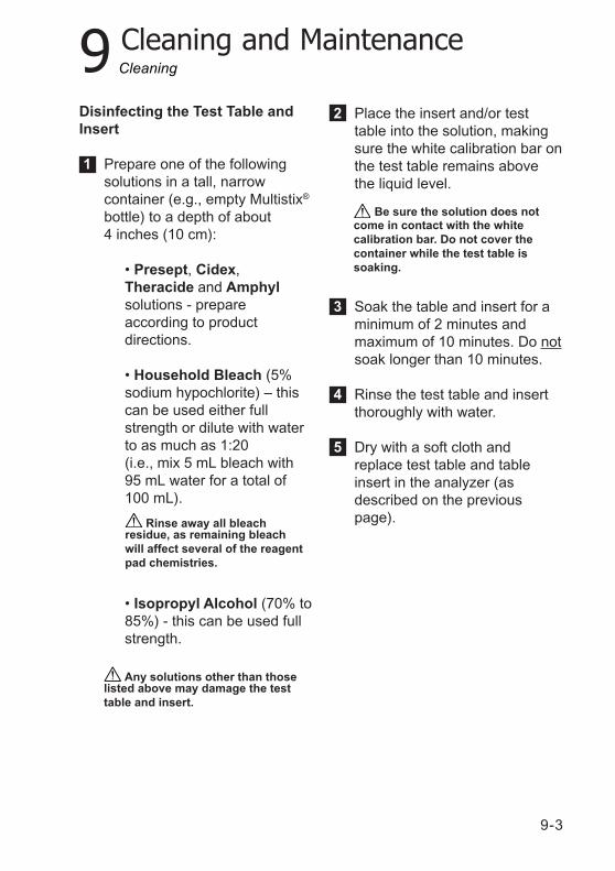
9-3
9 Cleaning and Maintenance
Disinfecting the Test Table andInsert
1 Prepare one of the followingsolutions in a tall, narrowcontainer (e.g., empty Multistix®
bottle) to a depth of about4 inches (10 cm):
• Presept, Cidex,Theracide and Amphylsolutions - prepareaccording to productdirections.
• Household Bleach (5%sodium hypochlorite) – thiscan be used either fullstrength or dilute with waterto as much as 1:20(i.e., mix 5 mL bleach with95 mL water for a total of100 mL).
• Isopropyl Alcohol (70% to85%) - this can be used fullstrength.
2 Place the insert and/or testtable into the solution, makingsure the white calibration bar onthe test table remains abovethe liquid level.
3 Soak the table and insert for aminimum of 2 minutes andmaximum of 10 minutes. Do notsoak longer than 10 minutes.
4 Rinse the test table and insertthoroughly with water.
5 Dry with a soft cloth andreplace test table and tableinsert in the analyzer (asdescribed on the previouspage). Rinse away all bleach
residue, as remaining bleachwill affect several of the reagentpad chemistries.
Any solutions other than thoselisted above may damage the testtable and insert.
Be sure the solution does notcome in contact with the whitecalibration bar. Do not cover thecontainer while the test table issoaking.
Cleaning
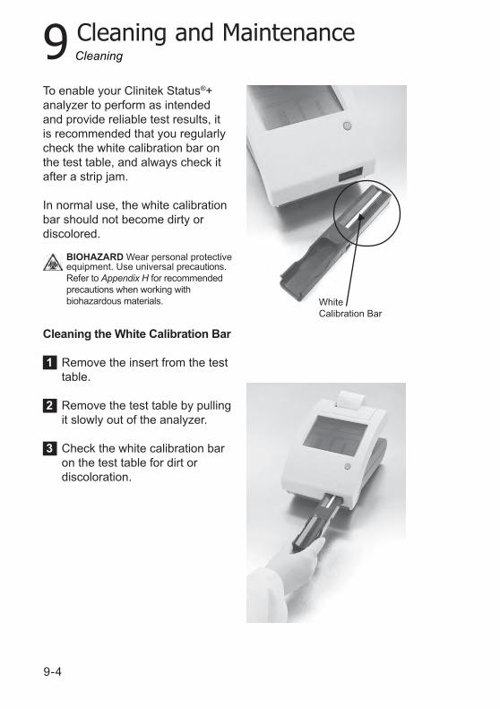
9-4
9 Cleaning and MaintenanceCleaning
WhiteCalibration Bar
BIOHAZARD Wear personal protectiveequipment. Use universal precautions.Refer to Appendix H for recommendedprecautions when working withbiohazardous materials.
To enable your Clinitek Status®+analyzer to perform as intendedand provide reliable test results, itis recommended that you regularlycheck the white calibration bar onthe test table, and always check itafter a strip jam.
In normal use, the white calibrationbar should not become dirty ordiscolored.
Cleaning the White Calibration Bar
1 Remove the insert from the testtable.
2 Remove the test table by pullingit slowly out of the analyzer.
3 Check the white calibration baron the test table for dirt ordiscoloration.
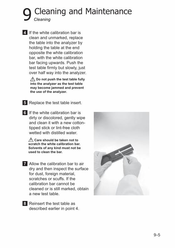
9-5
9 Cleaning and Maintenance
Care should be taken not toscratch the white calibration bar.Solvents of any kind must not beused to clean the bar.
Cleaning
Do not push the test table fullyinto the analyzer as the test tablemay become jammed and preventthe use of the analyzer.
4 If the white calibration bar isclean and unmarked, replacethe table into the analyzer byholding the table at the endopposite the white calibrationbar, with the white calibrationbar facing upwards. Push thetest table firmly but slowly, justover half way into the analyzer.
5 Replace the test table insert.
6 If the white calibration bar isdirty or discolored, gently wipeand clean it with a new cotton-tipped stick or lint-free clothwetted with distilled water.
7 Allow the calibration bar to airdry and then inspect the surfacefor dust, foreign material,scratches or scuffs. If thecalibration bar cannot becleaned or is still marked, obtaina new test table.
8 Reinsert the test table asdescribed earlier in point 4.
9-6
9 Cleaning and Maintenance
Always keep the outside of theClinitek Status+ analyzer clean andfree of dust.
1 Turn the analyzer off bypressing the on/off button for2 seconds.
2 Wipe the outside (including thedisplay) with a damp (not wet)cloth and a mild detergent.
Do not use any type ofsolvent, oil, grease, silicone spray,or lubrication on the analyzer.
Do not spray the glass cleanerdirectly onto the screen. Do not uselaboratory wipes, such as Kimwipes,since they may scratch the screen.
Care should be taken to avoidliquid from entering the printercompartment.
The display may be disinfectedusing the same solutions as for the testtable (see earlier in this section). Wipethe solution on and allow to remain for10 minutes. Wipe clean using a cleancloth dampened with water, then dry.
Cleaning
BIOHAZARD Wear personal protectiveequipment. Use universal precautions.Refer to Appendix H for recommendedprecautions when working withbiohazardous materials.
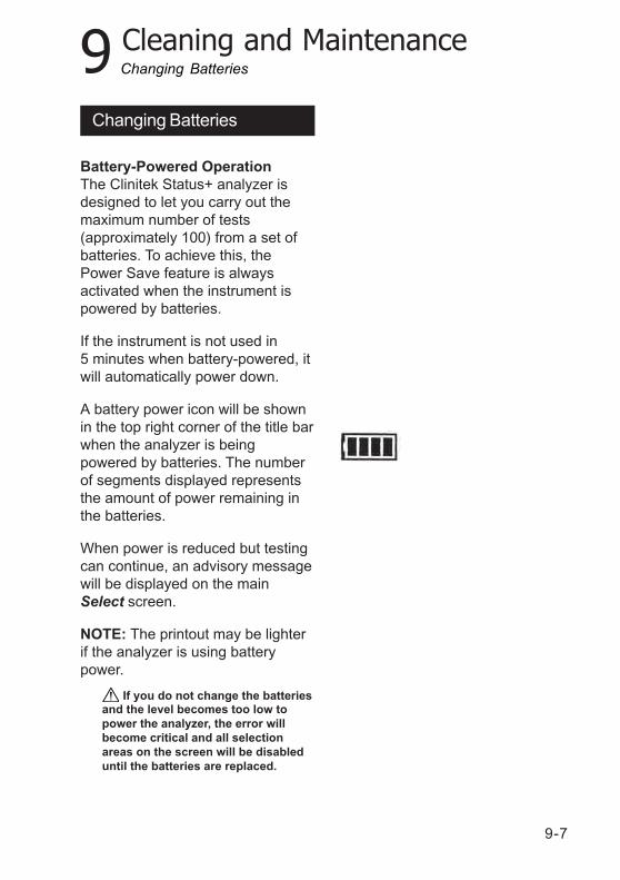
9-7
9 Cleaning and Maintenance
Battery-Powered OperationThe Clinitek Status+ analyzer isdesigned to let you carry out themaximum number of tests(approximately 100) from a set ofbatteries. To achieve this, thePower Save feature is alwaysactivated when the instrument ispowered by batteries.
If the instrument is not used in5 minutes when battery-powered, itwill automatically power down.
A battery power icon will be shownin the top right corner of the title barwhen the analyzer is beingpowered by batteries. The numberof segments displayed representsthe amount of power remaining inthe batteries.
When power is reduced but testingcan continue, an advisory messagewill be displayed on the mainSelect screen.
NOTE: The printout may be lighterif the analyzer is using batterypower.
If you do not change the batteriesand the level becomes too low topower the analyzer, the error willbecome critical and all selectionareas on the screen will be disableduntil the batteries are replaced.
Changing Batteries
Changing Batteries

9-8
9 Cleaning and Maintenance
Remove the test table from theanalyzer. Next, place the analyzeron its side and remove the batterycover by pressing down on the taband pulling out. Remove currentbatteries. Place 6 new AA-sizebatteries into the analyzer. Replacethe battery cover and turn theinstrument back onto its base.
Changing Batteries
10-1
10 Appendices
Appendix A: Local Technical Support Providers and Distributors
Appendix A: Local Technical Support Providers and Distributors
Legal InformationTo contact the legal representative for Siemens Healthcare Diagnosticswithin the European community, contact the Siemens AuthorizedRepresentative. To order supplies or replacement parts, or to obtainservice, contact your local technical support provider.
Siemens Healthcare Diagnostics Authorized RepresentativeSiemens Healthcare Diagnostics Ltd.Sir William Siemens Sq.Frimley, Camberley, GU16 8QD UK
Siemens Healthcare Diagnostics Ltd.Sir William Siemens Sq.Frimley, Camberley, GU16 8QD, UK
Siemens Healthcare Diagnostics Inc.Tarrytown, NY 10591-5097 USA
Siemens Healthcare Diagnostics Inc.511 Benedict AvenueTarrytown, NY 10591 5097 USA
Siemens Healthcare Diagnostics Pty Ltd885 Mountain HighwayBayswater Victoria 3153Australia
www.siemens.com/diagnostics
Origin: UK
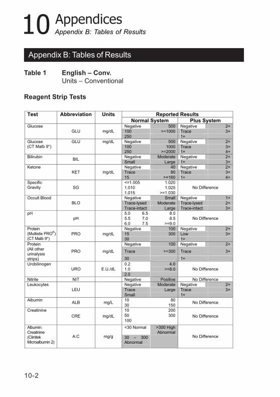
10-2
10 Appendices
Table 1 English – Conv.Units – Conventional
Reagent Strip Tests
Appendix B: Tables of Results
Appendix B: Tables of Results
Reported Results Test Abbreviation Units
Normal System Plus System Negative 500 Negative 2+
100 >=1000 Trace 3+
Glucose
GLU mg/dL
250 1+
Negative 500 Negative 2+ Glucose (CT Malb 9*)
GLU mg/dL
100 250
1000 >=2000
Trace 1+
3+ 4+
Negative Moderate Negative 2+ Bilirubin BIL
Small Large 1+ 3+
Negative 40 Negative 2+
Trace 80 Trace 3+
Ketone
KET mg/dL
15 >=160 1+ 4+
<=1.005 1.020
1.010 1.025
Specific Gravity SG
1.015 >=1.030
No Difference
Negative Small Negative 1+
Trace-lysed Moderate Trace-lysed 2+
Occult Blood
BLO
Trace-intact Large Trace-intact 3+
5.0 6.5 8.0
5.5 7.0 8.5
pH
pH
6.0 7.5 >=9.0
No Difference
Negative 100 Negative 2+
PRO mg/dL 15 300 Low 3+
Protein (Multistix PRO
®)
(CT Malb 9*) 30 1+
Negative 100 Negative 2+
PRO mg/dL Trace >=300 Trace 3+
Protein (All other urinalysis strips) 30 1+
0.2 4.0
1.0 >=8.0
Urobilinogen
URO E.U./dL
2.0
No Difference
Nitrite NIT Negative Positive No Difference
Negative Moderate Negative 2+
Trace Large Trace 3+
Leukocytes
LEU
Small 1+
10 80 Albumin ALB mg/L
30 150 No Difference
10 200
50 300
Creatinine
CRE mg/dL 100
No Difference
<30 Normal >300 High Abnormal
Albumin: Creatinine (Clinitek Microalbumin 2)
A:C mg/g 30 – 300 Abnormal
No Difference
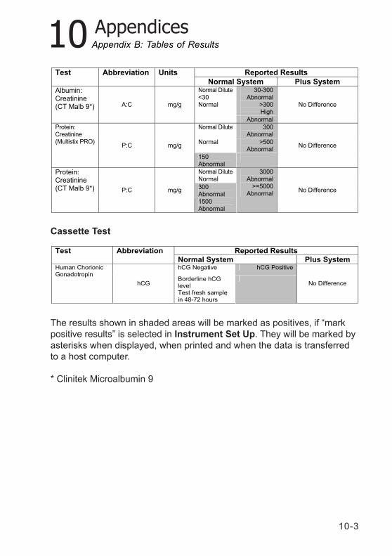
10-3
10 Appendices
Cassette Test
The results shown in shaded areas will be marked as positives, if “markpositive results” is selected in Instrument Set Up. They will be marked byasterisks when displayed, when printed and when the data is transferredto a host computer.
* Clinitek Microalbumin 9
Appendix B: Tables of Results
Reported Results Test Abbreviation Units
Normal System Plus System 30-300
Abnormal >300 High
Albumin: Creatinine (CT Malb 9*) A:C mg/g
Normal Dilute <30 Normal
Abnormal
No Difference
Normal Dilute
300 Abnormal
Normal >500 Abnormal
Protein: Creatinine (Multistix PRO)
P:C mg/g
150 Abnormal
No Difference
Normal Dilute Normal
Protein: Creatinine (CT Malb 9*) P:C mg/g
300 Abnormal 1500 Abnormal
3000 Abnormal
>=5000 Abnormal
No Difference
Reported Results Test Abbreviation
Normal System Plus System hCG Negative hCG Positive Human Chorionic
Gonadotropin
hCG Borderline hCG level Test fresh sample in 48-72 hours
No Difference
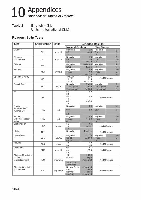
10-4
10 Appendices
Table 2 English – S.I.Units – International (S.I.)
Reagent Strip Tests
Appendix B: Tables of Results
Reported Results Test Abbreviation Units
Normal System Plus System Negative 28 Negative 2+
5.5 >=55 Trace 3+
Glucose
GLU mmol/L
14 1+
Negative Negative Glucose (CT Malb 9*) GLU mmol/L 5.5
14
28 55
>=110 Trace 1+
2+ 3+ 4+
Negative Moderate Negative 2+ Bilirubin BIL
Small Large 1+ 3+
Negative 3.9 Negative 2+
Trace 7.8 Trace 3+
Ketone
KET mmol/L
1.5 >=15.6 1+ 4+
<=1.005 1.020
1.010 1.025
Specific Gravity
SG
1.015 >=1.030
No Difference
Negative Ca 25 Negative 1+
Trace-lysed Ca 80 Trace-lysed 2+
Occult Blood
BLD Ery/µL
Trace-intact Ca 200 Trace-intact 3+
5.0 6.5
8.0
5.5 7.0
8.5
pH
pH
6.0 7.5
>=9.0
No Difference
Negative 1.0 Negative 2+
0.15 3.0 Low 3+
Protein (Multistix PRO
®)
(CT Malb 9*) PRO g/L
0.3 1+
Negative 1.0 Negative 2+
Trace >=3.0 Trace 3+
Protein (All other reagent strips)
PRO g/L
0.3 1+
3.2 66
16 >=131
Urobilinogen
UBG µmol/L
33
No Difference
Nitrite NIT Negative Positive No Difference
Negative Ca 125 Negative 2+
Ca 15 Ca 500 Trace 3+
Leukocytes
LEU Leu/µL
Ca 70 1+
10 80 Albumin ALB mg/L
30 150 No Difference
0.9 17.7
4.4 26.5
Creatinine
CRE mmol/L
8.8
No Difference
<3.4 Normal
>33.9 High
Abnormal
Albumin:Creatinine (Clinitek Microalbumin 2) A:C mg/mmol
3.4 – 33.9 Abnormal
No Difference
Normal Dilute <3.4 Normal
Albumin:Creatinine (CT Malb 9*)
A:C mg/mmol
3.4-33.9
Abnormal >33.9 High
Abnormal
No Difference
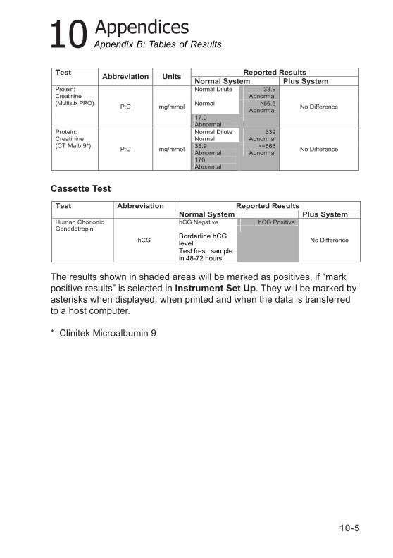
10-5
10 Appendices
Cassette Test
The results shown in shaded areas will be marked as positives, if “markpositive results” is selected in Instrument Set Up. They will be marked byasterisks when displayed, when printed and when the data is transferredto a host computer.
* Clinitek Microalbumin 9
Appendix B: Tables of Results
Reported Results Test Abbreviation
Normal System Plus System hCG Negative hCG Positive Human Chorionic
Gonadotropin
hCG
Borderline hCG level Test fresh sample in 48-72 hours
No Difference
Reported Results Test Abbreviation Units
Normal System Plus System Normal Dilute 33.9
Abnormal
Normal >56.6 Abnormal
Protein: Creatinine (Multistix PRO)
P:C mg/mmol
17.0 Abnormal
No Difference
Normal Dilute Normal
339 Abnormal
Protein: Creatinine (CT Malb 9*)
P:C mg/mmol 33.9 Abnormal 170 Abnormal
>=566 Abnormal
No Difference
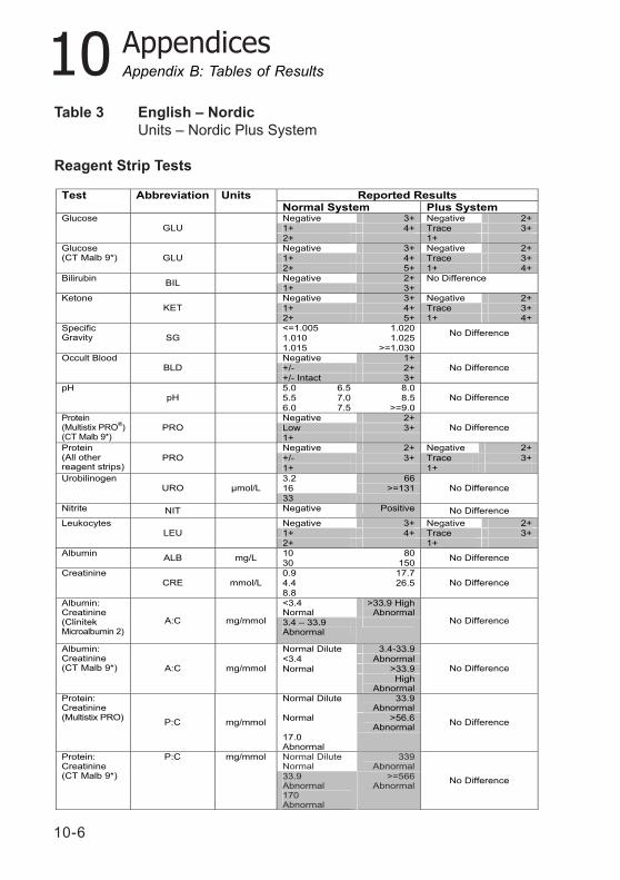
10-6
10 Appendices
Table 3 English – NordicUnits – Nordic Plus System
Reagent Strip Tests
Appendix B: Tables of Results
Reported Results Test Abbreviation Units Normal System Plus System Negative 3+ Negative 2+
1+ 4+ Trace 3+
Glucose GLU
2+ 1+ Negative 3+ Negative 2+
1+ 4+ Trace 3+
Glucose (CT Malb 9*) GLU
2+ 5+ 1+ 4+
Negative 2+ Bilirubin BIL
1+ 3+
No Difference
Negative 3+ Negative 2+
1+ 4+ Trace 3+
Ketone KET
2+ 5+ 1+ 4+
<=1.005 1.020 1.010 1.025
Specific Gravity SG
1.015 >=1.030
No Difference
Negative 1+
+/- 2+
Occult Blood BLD
+/- Intact 3+
No Difference
5.0 6.5 8.0
5.5 7.0 8.5
pH pH
6.0 7.5 >=9.0
No Difference
Negative 2+
Low 3+
Protein (Multistix PRO
®)
(CT Malb 9*) PRO
1+
No Difference
Negative 2+ Negative 2+
+/- 3+ Trace 3+
Protein (All other reagent strips)
PRO
1+ 1+
3.2 66 16 >=131
Urobilinogen URO µmol/L
33
No Difference
Nitrite NIT Negative Positive No Difference
Negative 3+ Negative 2+ 1+ 4+ Trace 3+
Leukocytes LEU
2+ 1+
10 80 Albumin ALB mg/L
30 150 No Difference
0.9 17.7
4.4 26.5
Creatinine CRE mmol/L
8.8
No Difference
<3.4 Normal
>33.9 High Abnormal
Albumin: Creatinine (Clinitek Microalbumin 2)
A:C mg/mmol 3.4 – 33.9 Abnormal
No Difference
Normal Dilute 3.4-33.9
<3.4 Abnormal
Normal >33.9
Albumin: Creatinine (CT Malb 9*) A:C mg/mmol
High Abnormal
No Difference
Normal Dilute 33.9 Abnormal
Normal >56.6 Abnormal
Protein: Creatinine (Multistix PRO)
P:C mg/mmol
17.0 Abnormal
No Difference
Normal Dilute Normal
339 Abnormal
Protein: Creatinine (CT Malb 9*)
P:C mg/mmol
33.9 Abnormal 170 Abnormal
>=566 Abnormal
No Difference
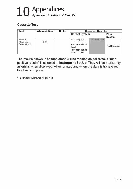
10-7
10 Appendices
Cassette Test
The results shown in shaded areas will be marked as positives, if “markpositive results” is selected in Instrument Set Up. They will be marked byasterisks when displayed, when printed and when the data is transferredto a host computer.
* Clinitek Microalbumin 9
Appendix B: Tables of Results
Reported Results Test Abbreviation Units
Normal System Plus System
hCG Negative hCG Positive Human Chorionic Gonadotropin
hCG
Borderline hCG level Test fresh sample in 48 72 hours
No Difference
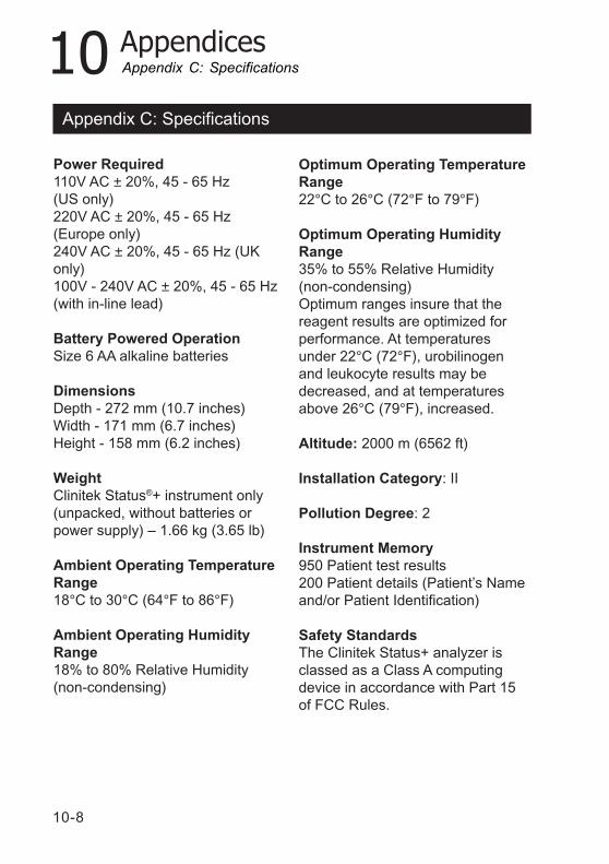
10-8
10 Appendices
Power Required110V AC ± 20%, 45 - 65 Hz(US only)220V AC ± 20%, 45 - 65 Hz(Europe only)240V AC ± 20%, 45 - 65 Hz (UKonly)100V - 240V AC ± 20%, 45 - 65 Hz(with in-line lead)
Battery Powered OperationSize 6 AA alkaline batteries
DimensionsDepth - 272 mm (10.7 inches)Width - 171 mm (6.7 inches)Height - 158 mm (6.2 inches)
WeightClinitek Status®+ instrument only(unpacked, without batteries orpower supply) – 1.66 kg (3.65 lb)
Ambient Operating TemperatureRange18°C to 30°C (64°F to 86°F)
Ambient Operating HumidityRange18% to 80% Relative Humidity(non-condensing)
Appendix C: Specifications
Optimum Operating TemperatureRange22°C to 26°C (72°F to 79°F)
Optimum Operating HumidityRange35% to 55% Relative Humidity(non-condensing)Optimum ranges insure that thereagent results are optimized forperformance. At temperaturesunder 22°C (72°F), urobilinogenand leukocyte results may bedecreased, and at temperaturesabove 26°C (79°F), increased.
Altitude: 2000 m (6562 ft)
Installation Category: II
Pollution Degree: 2
Instrument Memory950 Patient test results200 Patient details (Patient’s Nameand/or Patient Identification)
Safety StandardsThe Clinitek Status+ analyzer isclassed as a Class A computingdevice in accordance with Part 15of FCC Rules.
Appendix C: Specifications
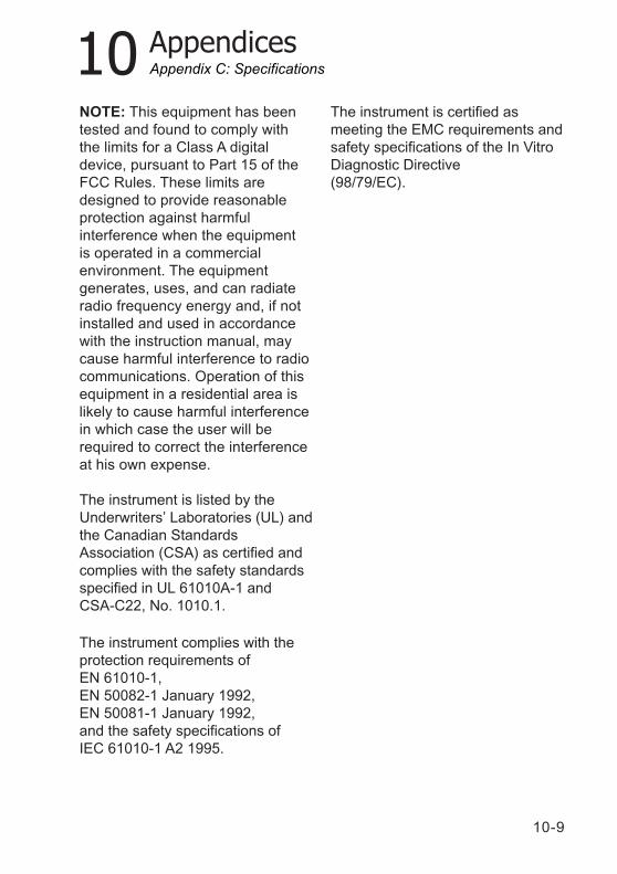
10-9
10 Appendices
The instrument complies with theprotection requirements ofEN 61010-1,EN 50082-1 January 1992,EN 50081-1 January 1992,and the safety specifications ofIEC 61010-1 A2 1995.
NOTE: This equipment has beentested and found to comply withthe limits for a Class A digitaldevice, pursuant to Part 15 of theFCC Rules. These limits aredesigned to provide reasonableprotection against harmfulinterference when the equipmentis operated in a commercialenvironment. The equipmentgenerates, uses, and can radiateradio frequency energy and, if notinstalled and used in accordancewith the instruction manual, maycause harmful interference to radiocommunications. Operation of thisequipment in a residential area islikely to cause harmful interferencein which case the user will berequired to correct the interferenceat his own expense.
The instrument is listed by theUnderwriters’ Laboratories (UL) andthe Canadian StandardsAssociation (CSA) as certified andcomplies with the safety standardsspecified in UL 61010A-1 andCSA-C22, No. 1010.1.
Appendix C: Specifications
The instrument is certified asmeeting the EMC requirements andsafety specifications of the In VitroDiagnostic Directive(98/79/EC).
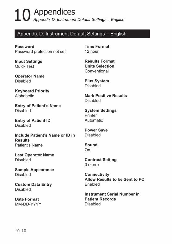
10-10
10 Appendices
PasswordPassword protection not set
Input SettingsQuick Test
Operator NameDisabled
Keyboard PriorityAlphabetic
Entry of Patient’s NameDisabled
Entry of Patient IDDisabled
Include Patient’s Name or ID inResultsPatient’s Name
Last Operator NameDisabled
Sample AppearanceDisabled
Custom Data EntryDisabled
Date FormatMM-DD-YYYY
Appendix D: Instrument Default Settings – English
Time Format12 hour
Results FormatUnits SelectionConventional
Plus SystemDisabled
Mark Positive ResultsDisabled
System SettingsPrinterAutomatic
Power SaveDisabled
SoundOn
Contrast Setting0 (zero)
ConnectivityAllow Results to be Sent to PCEnabled
Instrument Serial Number inPatient RecordsDisabled
Appendix D: Instrument Default Settings – English
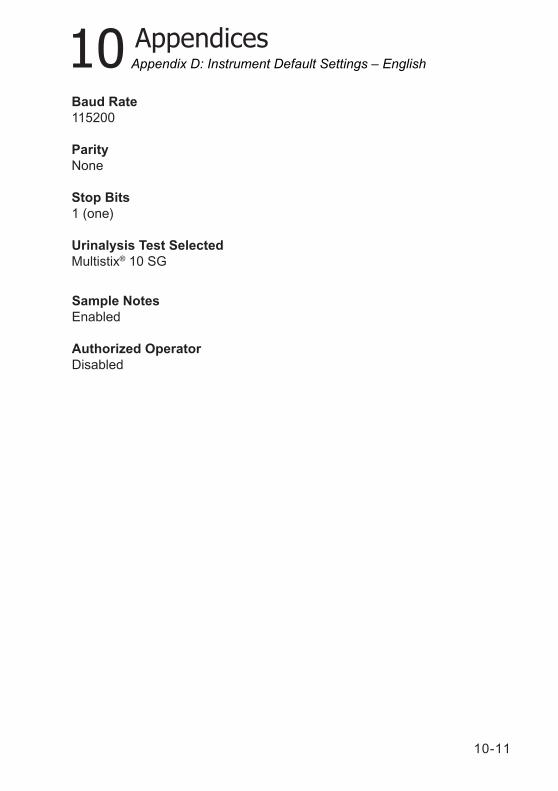
10-11
10 Appendices
Baud Rate115200
ParityNone
Stop Bits1 (one)
Urinalysis Test SelectedMultistix® 10 SG
Appendix D: Instrument Default Settings – English
Sample NotesEnabled
Authorized OperatorDisabled
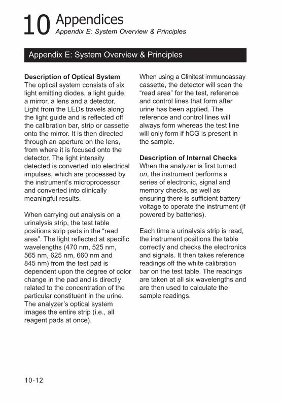
10-12
10 Appendices
Appendix E: System Overview & Principles
Description of Optical SystemThe optical system consists of sixlight emitting diodes, a light guide,a mirror, a lens and a detector.Light from the LEDs travels alongthe light guide and is reflected offthe calibration bar, strip or cassetteonto the mirror. It is then directedthrough an aperture on the lens,from where it is focused onto thedetector. The light intensitydetected is converted into electricalimpulses, which are processed bythe instrument’s microprocessorand converted into clinicallymeaningful results.
When carrying out analysis on aurinalysis strip, the test tablepositions strip pads in the “readarea”. The light reflected at specificwavelengths (470 nm, 525 nm,565 nm, 625 nm, 660 nm and845 nm) from the test pad isdependent upon the degree of colorchange in the pad and is directlyrelated to the concentration of theparticular constituent in the urine.The analyzer’s optical systemimages the entire strip (i.e., allreagent pads at once).
When using a Clinitest immunoassaycassette, the detector will scan the“read area” for the test, referenceand control lines that form afterurine has been applied. Thereference and control lines willalways form whereas the test linewill only form if hCG is present inthe sample.
Description of Internal ChecksWhen the analyzer is first turnedon, the instrument performs aseries of electronic, signal andmemory checks, as well asensuring there is sufficient batteryvoltage to operate the instrument (ifpowered by batteries).
Each time a urinalysis strip is read,the instrument positions the tablecorrectly and checks the electronicsand signals. It then takes referencereadings off the white calibrationbar on the test table. The readingsare taken at all six wavelengths andare then used to calculate thesample readings.
Appendix E: System Overview & Principles
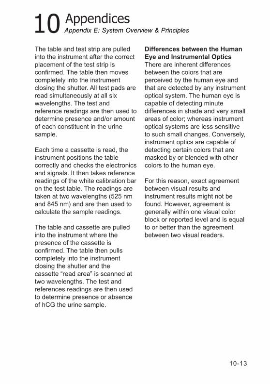
10-13
10 Appendices
The table and test strip are pulledinto the instrument after the correctplacement of the test strip isconfirmed. The table then movescompletely into the instrumentclosing the shutter. All test pads areread simultaneously at all sixwavelengths. The test andreference readings are then used todetermine presence and/or amountof each constituent in the urinesample.
Each time a cassette is read, theinstrument positions the tablecorrectly and checks the electronicsand signals. It then takes referencereadings of the white calibration baron the test table. The readings aretaken at two wavelengths (525 nmand 845 nm) and are then used tocalculate the sample readings.
The table and cassette are pulledinto the instrument where thepresence of the cassette isconfirmed. The table then pullscompletely into the instrumentclosing the shutter and thecassette “read area” is scanned attwo wavelengths. The test andreferences readings are then usedto determine presence or absenceof hCG the urine sample.
Differences between the HumanEye and Instrumental OpticsThere are inherent differencesbetween the colors that areperceived by the human eye andthat are detected by any instrumentoptical system. The human eye iscapable of detecting minutedifferences in shade and very smallareas of color; whereas instrumentoptical systems are less sensitiveto such small changes. Conversely,instrument optics are capable ofdetecting certain colors that aremasked by or blended with othercolors to the human eye.
For this reason, exact agreementbetween visual results andinstrument results might not befound. However, agreement isgenerally within one visual colorblock or reported level and is equalto or better than the agreementbetween two visual readers.
Appendix E: System Overview & Principles

10-14
10 AppendicesAppendix E: System Overview & Principles
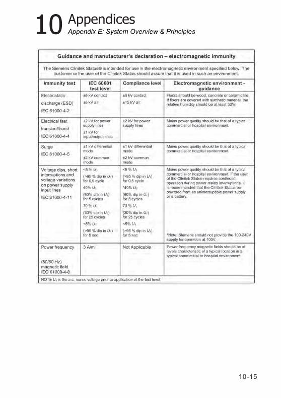
10-15
10 AppendicesAppendix E: System Overview & Principles
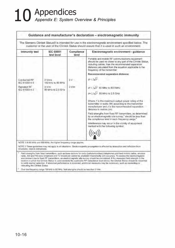
10-16
10 AppendicesAppendix E: System Overview & Principles
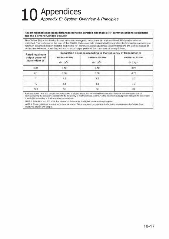
10-17
10 AppendicesAppendix E: System Overview & Principles

10-18
10 AppendicesAppendix F: Training & Educational Materials
Chek-Stix® Positive and Negative control strips areavailable for use in your training program for routine urinestrip testing (for supply information see Appendix A, LocalTechnical Support Providers and Distributors). Follow thepackage insert for instruction on preparation and testing.
Appendix F: Training & Educational Materials
10-19
10 AppendicesAppendix G: Sample Interference Notes
Appendix G: Sample Interference Notes
Sample Interference Notes inform the user about test results that can beaffected by components detected in the urine sample.
Depending upon the strip and sample, Sample Interference Notes includethe following:
High SG may cause falsely lowered GLU results.Elevated GLU may cause falsely lowered LEU results.Visibly bloody urine may cause falsely elevated PRO results.High SG may cause falsely lowered LEU results.High pH may cause falsely elevated PRO results.
10-20
10 AppendicesAppendix H: Safety Information
Protecting Yourself fromBiohazards
This information summarizes theestablished guidelines for handlinglaboratory biohazards. Thissummary is based on theguidelines developed by theCenters for Disease Control, theClinical and Laboratory StandardsInstitute, and the OccupationalSafety and Health Administration.
Use this summary for generalinformation only. It is not intendedto replace or supplement yourlaboratory or hospital biohazardcontrol procedures.
By definition, a biohazardouscondition is a situation involvinginfectious agents biological innature, such as the hepatitis Bvirus, the human immunodeficiencyvirus, and the tuberculosisbacterium. These infectious agentsmay be present in human bloodand blood products and in otherbody fluids.
The following are the major sourcesof contamination when handlingpotentially infectious agents:
needlesticks
hand-to-mouth contact
hand-to-eye contact
direct contact with superficialcuts, open wounds, andother skin conditions thatmay permit absorption intosubcutaneous skin layers
splashes or aerosol contactwith skin and eyes
To prevent accidentalcontamination in a clinicallaboratory, strictly adhere to thefollowing procedures:
Wear gloves while servicingparts of the system that havecontact with body fluids suchas serum, plasma, urine, orwhole blood.
Wash your hands beforegoing from a contaminatedarea to a noncontaminatedarea, or when you remove orchange gloves.
Perform procedures carefullyto minimize aerosolformation.
Wear facial protection whensplatter or aerosol formationare possible.
Wear personal protectiveequipment such as safetyglasses, gloves, lab coats oraprons when working withpossible biohazardcontaminants.
Appendix H: Safety Information
10-21
10 Appendices
Keep your hands away fromyour face.
Cover all superficial cuts andwounds before starting anywork.
Dispose of contaminatedmaterials according to yourlaboratory’s biohazardcontrol procedures.
Keep your work areadisinfected.
Disinfect tools and otheritems that have been nearany part of the systemsample path or waste areawith 10% v/v bleach.
Do not eat, drink, smoke, orapply cosmetics or contactlenses while in thelaboratory.
Do not mouth pipet anyliquid, including water.
Do not place tools or anyother items in your mouth.
Do not use the biohazardsink for personal cleaningsuch as rinsing coffee cupsor washing hands.
Do not recap, purposely bend, cut,break, remove from disposablesyringes, or otherwise manipulateneedles by hand. Needlestickinjuries may result.
References
1. Centers for Disease Control.Update: Universal precautions forprevention of transmission ofhuman immunodeficiency virus,hepatitis B virus and otherbloodborne pathogens inhealthcare settings. 1988. MMWR,37:377-382, 387, 388.
2. Clinical and LaboratoryStandards Institute (formerlyNCCLS). Protection of LaboratoryWorkers from OccupationallyAcquired Infections; ApprovedGuideline - Third Edition. Wayne,PA: Clinical and LaboratoryStandards Institute; 2005. CLSIDocument M29-A3. [ISBN 1-56238-567-4].
3. Federal Occupational Safetyand Health Administration.Bloodborne Pathogens Standard.29 CFR 1910. 1030.
Appendix H: Safety Information

10-22
10 Appendices
Appendix I: Clinitek Status®+ Intended Use and Indications for Use
Appendix I: Clinitek Status®+ Intended Use and Indications for Use
The Clinitek Status®+ UrineChemistry Analyzer is a portableeasy to use analyzer. It isdesigned to read only SiemensReagent Strips for Urinalysisand Clinitest® hCG tests.
This analyzer is intended for themeasurement of the following inurine: Albumin, Bilirubin, Blood(Occult), Creatinine, Glucose,Ketone, Leukocytes, Nitrite, pH,Protein, Protein-to-CreatinineRatio, Albumin-to-CreatinineRatio, Specific Gravity,Urobilinogen, and humanChorionic Gonadotropin (hCG).
These measurements are usedto assist diagnosis in thefollowing areas:
Kidney FunctionUrinary tract infectionsMetabolic disorders(e.g. diabetes mellitus)Liver FunctionPregnancy
Tests performed using theClinitek Status®+ Analyzer areintended for in vitro diagnosticuse only.
The Clinitek Status®+ Analyzeris intended for near patient(point-of-care) facilities andcentralized laboratory locations.
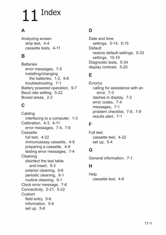
11 Index
11-1
A
Analyzing screenstrip test, 4-4cassette tests, 4-11
B
Batterieserror messages, 7-5installing/changing
the batteries, 1-2, 9-8troubleshooting, 7-1
Battery powered operation, 9-7Baud rate setting, 5-22Boxed areas, 2-2
C
Cablinginterfacing to a computer, 1-3
Calibration, 4-3, 4-11error messages, 7-4, 7-6
Cassettefull test, 4-22immunoassay cassette, 4-9preparing a cassette, 4-9testing error messages, 7-4
Cleaningdisinfect the test table
and insert, 9-3exterior cleaning, 9-6periodic cleaning, 9-1routine cleaning, 9-1
Clock error message, 7-6Connectivity, 5-21, 5-22Custom
field entry, 5-6information, 5-6set up, 5-6
D
Date and timesettings, 5-14, 5-15
Defaultrestore default settings, 5-33settings, 10-10
Diagnostic tests, 5-34display contrast, 5-20
E
Error(s)calling for assistance with an
error, 7-3dashes in display, 7-2error codes, 7-4messages, 7-1problem checklist, 7-8, 7-9results alert, 7-1
F
Full testcassette test, 4-22set up, 5-4
G
General information, 7-1
H
Helpcassette test, 4-8
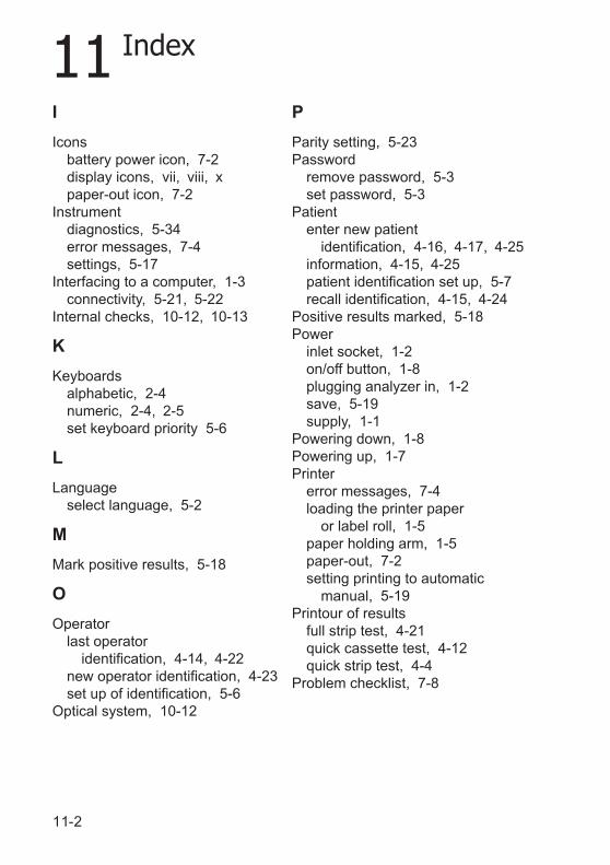
11 Index
11-2
I
Iconsbattery power icon, 7-2display icons, vii, viii, xpaper-out icon, 7-2
Instrumentdiagnostics, 5-34error messages, 7-4settings, 5-17
Interfacing to a computer, 1-3connectivity, 5-21, 5-22
Internal checks, 10-12, 10-13
K
Keyboardsalphabetic, 2-4numeric, 2-4, 2-5set keyboard priority 5-6
L
Languageselect language, 5-2
M
Mark positive results, 5-18
O
Operatorlast operator
identification, 4-14, 4-22new operator identification, 4-23set up of identification, 5-6
Optical system, 10-12
P
Parity setting, 5-23Password
remove password, 5-3set password, 5-3
Patiententer new patient
identification, 4-16, 4-17, 4-25information, 4-15, 4-25patient identification set up, 5-7recall identification, 4-15, 4-24
Positive results marked, 5-18Power
inlet socket, 1-2on/off button, 1-8plugging analyzer in, 1-2save, 5-19supply, 1-1
Powering down, 1-8Powering up, 1-7Printer
error messages, 7-4loading the printer paper
or label roll, 1-5paper holding arm, 1-5paper-out, 7-2setting printing to automatic
manual, 5-19Printour of results
full strip test, 4-21quick cassette test, 4-12quick strip test, 4-4
Problem checklist, 7-8
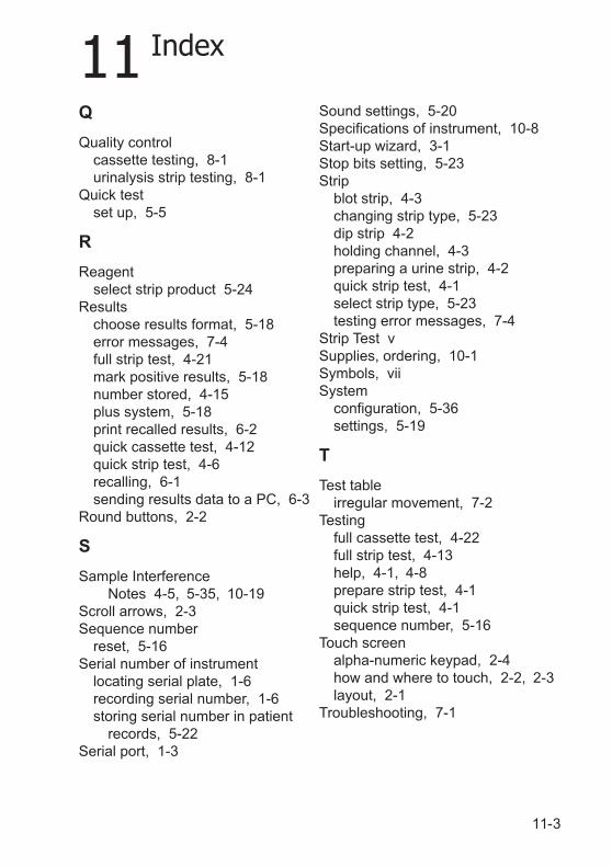
11 Index
11-3
Q
Quality controlcassette testing, 8-1urinalysis strip testing, 8-1
Quick testset up, 5-5
R
Reagentselect strip product 5-24
Resultschoose results format, 5-18error messages, 7-4full strip test, 4-21mark positive results, 5-18number stored, 4-15plus system, 5-18print recalled results, 6-2quick cassette test, 4-12quick strip test, 4-6recalling, 6-1sending results data to a PC, 6-3
Round buttons, 2-2
S
Sample InterferenceNotes 4-5, 5-35, 10-19
Scroll arrows, 2-3Sequence number
reset, 5-16Serial number of instrument
locating serial plate, 1-6recording serial number, 1-6storing serial number in patient
records, 5-22Serial port, 1-3
Sound settings, 5-20Specifications of instrument, 10-8Start-up wizard, 3-1Stop bits setting, 5-23Strip
blot strip, 4-3changing strip type, 5-23dip strip 4-2holding channel, 4-3preparing a urine strip, 4-2quick strip test, 4-1select strip type, 5-23testing error messages, 7-4
Strip Test vSupplies, ordering, 10-1Symbols, viiSystem
configuration, 5-36settings, 5-19
T
Test tableirregular movement, 7-2
Testingfull cassette test, 4-22full strip test, 4-13help, 4-1, 4-8prepare strip test, 4-1quick strip test, 4-1sequence number, 5-16
Touch screenalpha-numeric keypad, 2-4how and where to touch, 2-2, 2-3layout, 2-1
Troubleshooting, 7-1
11 Index
11-4
U
Unitsconventional units, 5-17
Unpacking, 1-1Urinalysis test, 5-23, 5-24Urine sample
clarity, 4-19color, 4-18settings, 5-8visual appearance, 4-18, 4-19
W
Warranty, 7-3registration card, 1-6
Recommended