2005/ IV
188
News from Rohde & Schwarz
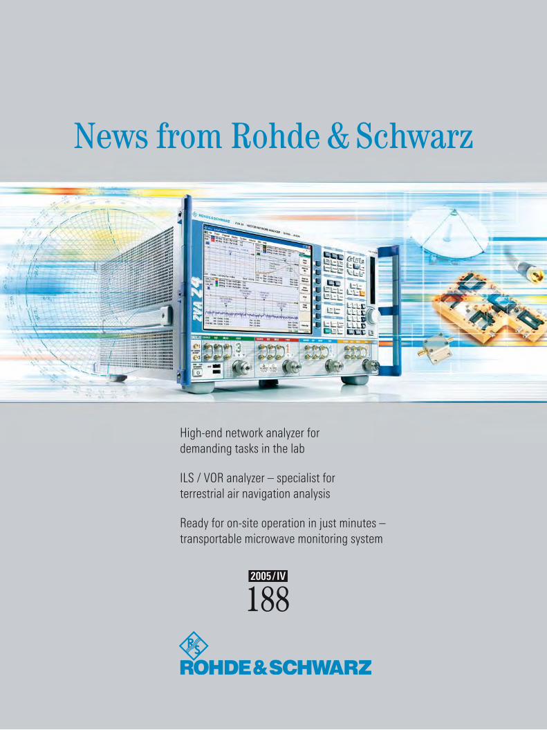
High-end network analyzer for demanding tasks in the lab
ILS / VOR analyzer – specialist for terrestrial air navigation analysis
Ready for on-site operation in just minutes – transportable microwave monitoring system

�
The new generation of R&S®ZVA high-end net-work analyzers offers high measurement speed,
maximum dynamic range and extremely high versatility and accuracy – ideal prerequisites
for complex measurement tasks. On top of this, it features an easy and intuitive operating con-
cept (page 26).
The WLAN Protocol Tester R&S®PTW70 of course provides all functions required for con-formance tests. But it far exceeds these stan-dard requirements… (page 22).
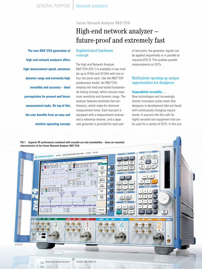
The R&S®ZVA is outstanding for its superior RF performance combined with versatile use and extendability (page 26).
44466
MOBILE RADIO
TETRA radio systemsTETRA Mobile Radio System ACCESSNET®-TScalable PMR networks: The architecture is what counts ..............................................4
Radiocommunications testersUniversal Radio Communication Tester R&S®CMU�00Measurements and signaling tests in the dual transfer mode ........................................8Adjustment of polar modulators in production ...............................................................1�
R&S®CMU�00 / R&S®CTRU-G / -WStandardized test solutions for PoC mobile phones .......................................................14
Bluetooth® RF Testers R&S®CBT / R&S®CBT3�Transmitter and receiver measurements for Bluetooth® V�.0 + EDR ............................16
Signal generatorsVector Signal Generator R&S®SMU�00ASignals for testing multicarrier power amplifiers ...........................................................19
WPAN / WLAN / WWAN
Protocol testersWLAN Protocol Tester R&S®PTW70Multimode protocol analysis in WLANs .........................................................................��
GENERAL PURPOSE
Network analyzersVector Network Analyzer R&S®ZVAHigh-end network analyzer – future-proof and extremely fast ......................................�6
News from Rohde&Schwarz Number 188 (�005/ IV)
NUMBER 188 �005/ IV Volume 45
3
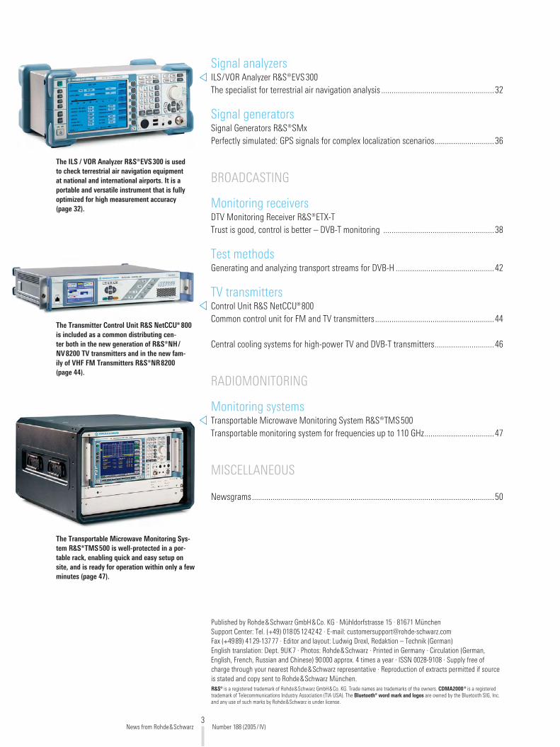
The ILS / VOR Analyzer R&S®EVS300 is used to check terrestrial air navigation equipment at national and international airports. It is a portable and versatile instrument that is fully optimized for high measurement accuracy (page 32).
The Transmitter Control Unit R&S NetCCU® 800 is included as a common distributing cen-ter both in the new generation of R&S®NH/NV8200 TV transmitters and in the new fam-ily of VHF FM Transmitters R&S®NR8200 (page 44).
The Transportable Microwave Monitoring Sys-tem R&S®TMS500 is well-protected in a por-table rack, enabling quick and easy setup on site, and is ready for operation within only a few minutes (page 47).
Signal analyzersILS/VOR Analyzer R&S®EVS300The specialist for terrestrial air navigation analysis .......................................................3�
Signal generatorsSignal Generators R&S®SMxPerfectly simulated: GPS signals for complex localization scenarios .............................36
BROADCASTING
Monitoring receiversDTV Monitoring Receiver R&S®ETX-TTrust is good, control is better – DVB-T monitoring ......................................................38
Test methodsGenerating and analyzing transport streams for DVB-H ................................................4�
TV transmittersControl Unit R&S NetCCU®800Common control unit for FM and TV transmitters ..........................................................44
Central cooling systems for high-power TV and DVB-T transmitters .............................46
RADIOMONITORING
Monitoring systemsTransportable Microwave Monitoring System R&S®TMS500Transportable monitoring system for frequencies up to 110 GHz ..................................47
MISCELLANEOUS
Newsgrams ......................................................................................................................50
News from Rohde&Schwarz Number 188 (�005/ IV)
Published by Rohde&Schwarz GmbH&Co. KG · Mühldorfstrasse 15 · 81671 München Support Center: Tel. (+49) 018051�4�4� · E-mail: [email protected] Fax (+4989) 41�9-13777 · Editor and layout: Ludwig Drexl, Redaktion – Technik (German) English translation: Dept. 9UK7 · Photos: Rohde&Schwarz · Printed in Germany · Circulation (German, English, French, Russian and Chinese) 90000 approx. 4 times a year · ISSN 00�8-9108 · Supply free of charge through your nearest Rohde&Schwarz representative · Reproduction of extracts permitted if source is stated and copy sent to Rohde&Schwarz München. R&S® is a registered trademark of Rohde&Schwarz GmbH&Co. KG. Trade names are trademarks of the owners. CDMA2000® is a registered trademark of Telecommunications Industry Association (TIA USA). The Bluetooth® word mark and logos are owned by the Bluetooth SIG, Inc. and any use of such marks by Rohde&Schwarz is under license.

4
TETRA Mobile Radio System ACCESSNET ®-T
Scalable PMR networks: The architecture is what counts
The Mobile Radio Communica-
tions Architecture IpMCA® from
Rohde&Schwarz defines a compre-
hensive technical and commercial
requirements profile for digital PMR
networks [1]. If these requirements
are taken into account when plan-
ning mission-critical communications
networks and are completely fulfilled
in the implementation phase, there
will be nothing to stop these networks
from being adapted quickly and cost-
effectively during their entire opera-
tional life.
In constant change
PMR networks undergo constant, some-times manifold changes. The causes for this are always linked directly or indirectly to the users in the network: The subscriber community may grow, alter its structure or be geographically rearranged – which always results in the need to adapt the digital infrastruc-ture. Quick, cost-effective adaptation of these professional networks should be possible during their entire operational life. PMR networks must therefore be scalable in at least the three following dimensions:
The radio coverage of the area to be covered and the channel capacity of individual network elements if sub-scriber density increases The number of subscribers organized in closed user groups The availability of individual net-work elements (scalable redundancy)
◆
◆
◆
Scalability of radio coverage and channel capacity
A cellular TETRA network is usually set up in two stages. In the first stage, it is made certain that the coverage area has enough base stations for transmit-ting signals in compliance with qual-ity requirements. One of the characteris-tics of quality radio coverage is sufficient overlapping of the coverage areas of adjacent base stations to ensure reliable handover of calls as mobile subscribers move from cell to cell.
When a network is being planned, the communications capacity to be provided by the network is distributed on the basis of the assumed subscriber densi-ties. For example, base stations in rural areas normally require fewer channels than those in urban areas.
As the number of subscribers rises, how-ever, it is usually necessary in a sec-ond stage to add channels to base sta-tions and to increase the capacity of the exchanges involved for routing and switching or even to install additional base stations.
The requirements defined in the Mobile Radio Communications Architecture IpMCA® specify the unlimited compat-ibility of the network elements, regard-less of how large a network is. The ACCESSNET®-T TETRA mobile radio net-work from Rohde&Schwarz fully meets this requirement. All network elements of the same type are compatible and can continue to be used if the network is expanded – no matter whether the net-work is a small, single-cell TETRA system or a nationwide network with hundreds of base stations.
Number of System Nodes IpSN®
Number of base stations
Configuration
1 36 In a network with only one exchange
1 30
In a network with multiple exchanges
� 60
3 90
4 1�0
FIG 1 Too many base stations to be connected? No problem! Cascading the System Node IpSN® (photo) allows you to connect up to 120 base stations.
News from Rohde&Schwarz Number 188 (�005/ IV)
TETRA radio systemsMOBILE RADIO
5
ACCESSNET®-T base stations are avail-able as indoor or outdoor models, and each can have one to eight carriers. The new System Node IpSN®, whose capacity can be increased to supply up to 1�0 base stations, is used as an exchange (FIG 1).
A number of System Nodes IpSN® can also be interconnected in a nonhierar-chical, meshed configuration. This not only makes it possible to configure very large networks but also, as described further below, provides a basis for mis-sion-critical, highly available mobile radio networks.
Adapting a network to the number of subscribers and user groups
Theoretically IpMCA® does not limit the number of subscribers, but in reality this number is limited by the communica-tions capacity installed and the agreed-on quality of service (QoS). Of particular importance with regard to mission-criti-cal communications networks is the abil-ity to manage closed user groups (vir-tual private networks, VPNs). A network must be able to adapt flexibly to rising subscriber numbers or additional user groups.
In VPNs several user groups share a common network, but the parts of the network allocated to each group remain hidden from the other groups. This also affects access to resources that is exclu-sively assigned to the different VPNs. VPNs are thus characterized by the fol-lowing:
Individualized physical address ranges in which calling numbers can be assigned in accordance with the organization‘s own concept as to how it should be mappedAssigned subscriber management
◆
◆
Own key management and authen-tication (in the case of end-to-end encryption)Own accesses to private automatic branch exchanges (PABXs)Own control centersOwn voice recordingOwn IP access points (IAPs) for rout-ing to the organization-internal intranet for packet-oriented data transmission (IP over TETRA)Own software applications that pro-vide user-group-specific solutions
Here, too, there is no objective limita-tion to the number of definable VPNs. What matters are the technical proper-ties of the network elements and com-ponents – for example, whether the net-work management system supports sep-
◆
◆
◆
◆
◆
◆
arate subscriber management for differ-ent address ranges and the associated calling numbers or whether all features that will be required later can be imple-mented in the mobile radio network.
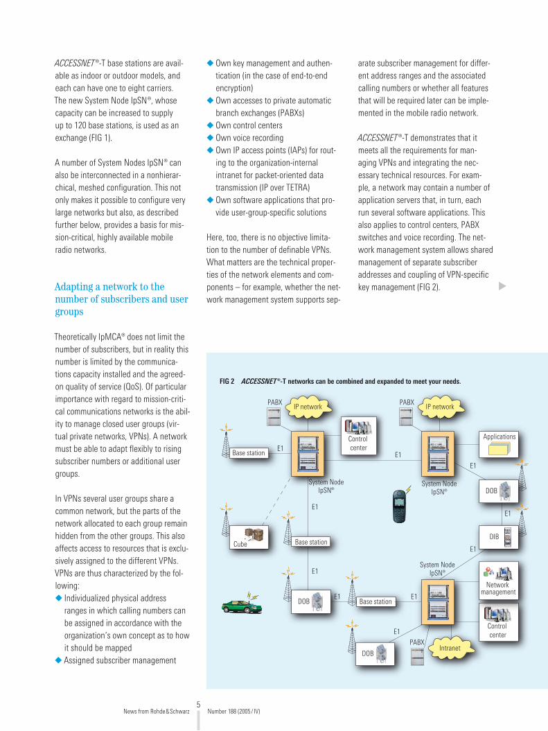
ACCESSNET®-T demonstrates that it meets all the requirements for man-aging VPNs and integrating the nec-essary technical resources. For exam-ple, a network may contain a number of application servers that, in turn, each run several software applications. This also applies to control centers, PABX switches and voice recording. The net-work management system allows shared management of separate subscriber addresses and coupling of VPN-specific key management (FIG �).
PABX
E1
E1
E1
Applications
E1
E1
E1
E1
E1
E1
E1
IP network
Base station
Base station
Base station
Controlcenter
Cube
DOB
DOB
PABXIP network
PABXIntranet
Controlcenter
Networkmanagement
DOB
DIB
System NodeIpSN®
System NodeIpSN®
System NodeIpSN®
FIG 2 ACCESSNET®-T networks can be combined and expanded to meet your needs.
News from Rohde&Schwarz Number 188 (�005/ IV)
6
Redundancy based on needs
The overall availability of PMR networks is generally very high. However, this does not take into account threat sce-narios that are not caused by techni-cal problems. However, mission-critical communications networks must be safe-guarded not only against technical fail-ures, but also against uncontrollable nat-ural phenomena as well as against van-dalism or acts of terror.
Besides these aspects, it is important to know where failures occur. For example, the failure of radio coverage in an unin-habited wooded area must be evalu-ated differently than the failure of a cell containing a facility that requires spe-cial protection. Essential with all failures is how quickly they can be eliminated. In ideal cases, the system automatically remedies the failure; in extreme cases, the affected network elements have to be replaced by mobile units, for example by the ACCESSNET®-T Cube [�].
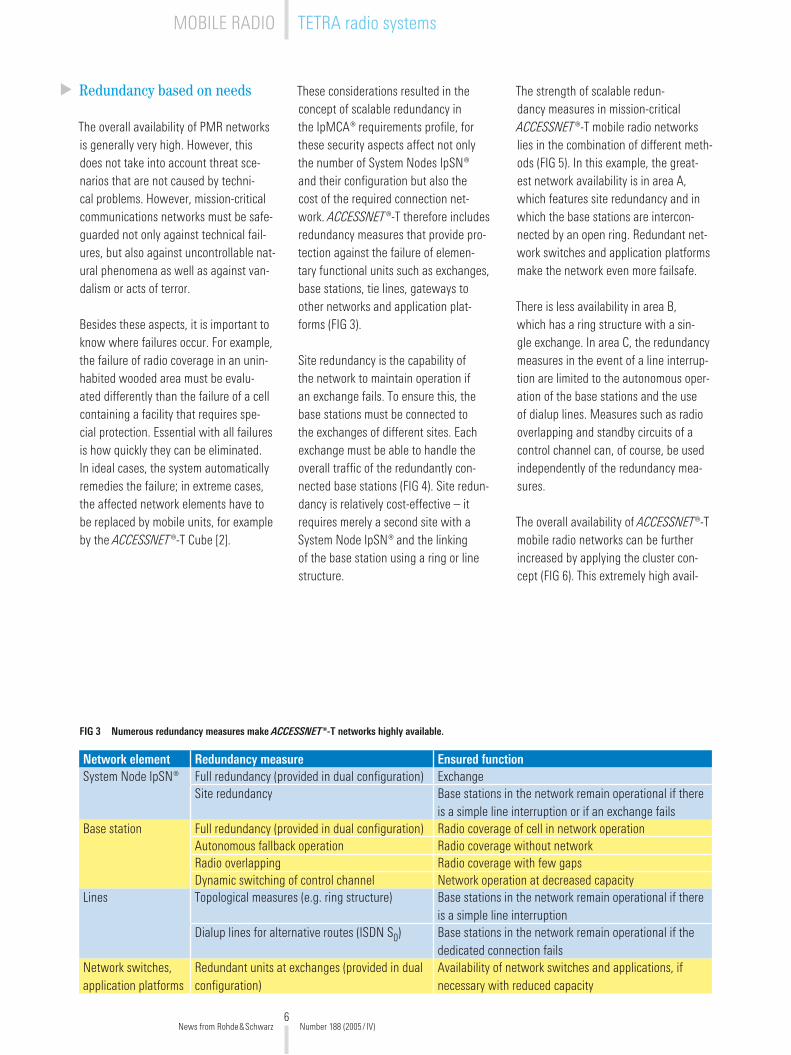
These considerations resulted in the concept of scalable redundancy in the IpMCA® requirements profile, for these security aspects affect not only the number of System Nodes IpSN® and their configuration but also the cost of the required connection net-work. ACCESSNET®-T therefore includes redundancy measures that provide pro-tection against the failure of elemen-tary functional units such as exchanges, base stations, tie lines, gateways to other networks and application plat-forms (FIG 3).
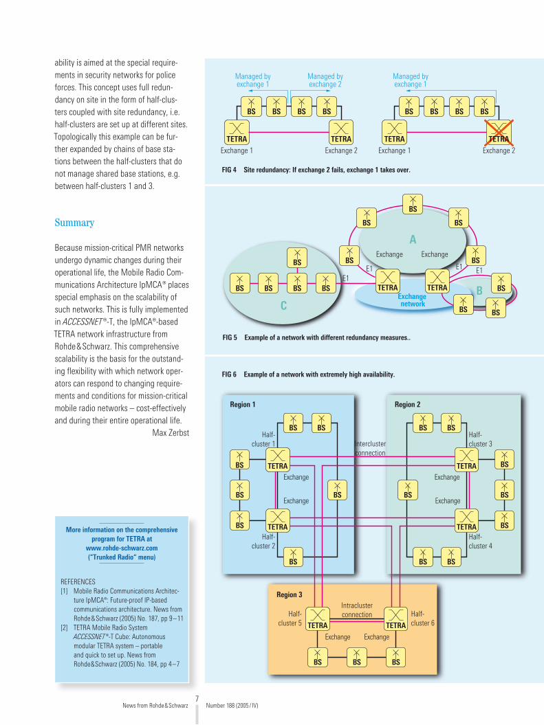
Site redundancy is the capability of the network to maintain operation if an exchange fails. To ensure this, the base stations must be connected to the exchanges of different sites. Each exchange must be able to handle the overall traffic of the redundantly con-nected base stations (FIG 4). Site redun-dancy is relatively cost-effective – it requires merely a second site with a System Node IpSN® and the linking of the base station using a ring or line structure.
Network element Redundancy measure Ensured functionSystem Node IpSN® Full redundancy (provided in dual configuration) Exchange
Site redundancy Base stations in the network remain operational if there is a simple line interruption or if an exchange fails
Base station Full redundancy (provided in dual configuration) Radio coverage of cell in network operationAutonomous fallback operation Radio coverage without networkRadio overlapping Radio coverage with few gapsDynamic switching of control channel Network operation at decreased capacity
Lines Topological measures (e.g. ring structure) Base stations in the network remain operational if there is a simple line interruption
Dialup lines for alternative routes (ISDN S0) Base stations in the network remain operational if the dedicated connection fails
Network switches, application platforms
Redundant units at exchanges (provided in dual configuration)
Availability of network switches and applications, if necessary with reduced capacity
FIG 3 Numerous redundancy measures make ACCESSNET®-T networks highly available.
The strength of scalable redun-dancy measures in mission-critical ACCESSNET®-T mobile radio networks lies in the combination of different meth-ods (FIG 5). In this example, the great-est network availability is in area A, which features site redundancy and in which the base stations are intercon-nected by an open ring. Redundant net-work switches and application platforms make the network even more failsafe.
There is less availability in area B, which has a ring structure with a sin-gle exchange. In area C, the redundancy measures in the event of a line interrup-tion are limited to the autonomous oper-ation of the base stations and the use of dialup lines. Measures such as radio overlapping and standby circuits of a control channel can, of course, be used independently of the redundancy mea-sures.
The overall availability of ACCESSNET®-T mobile radio networks can be further increased by applying the cluster con-cept (FIG 6). This extremely high avail-
News from Rohde&Schwarz Number 188 (�005/ IV)
MOBILE RADIO TETRA radio systems
7
ability is aimed at the special require-ments in security networks for police forces. This concept uses full redun-dancy on site in the form of half-clus-ters coupled with site redundancy, i.e. half-clusters are set up at different sites. Topologically this example can be fur-ther expanded by chains of base sta-tions between the half-clusters that do not manage shared base stations, e.g. between half-clusters 1 and 3.
Summary
Because mission-critical PMR networks undergo dynamic changes during their operational life, the Mobile Radio Com-munications Architecture IpMCA® places special emphasis on the scalability of such networks. This is fully implemented in ACCESSNET®-T, the IpMCA®-based TETRA network infrastructure from Rohde&Schwarz. This comprehensive scalability is the basis for the outstand-ing flexibility with which network oper-ators can respond to changing require-ments and conditions for mission-critical mobile radio networks – cost-effectively and during their entire operational life.
Max Zerbst
TETRATETRAExchange 1 Exchange 2
BSBS BS
Managed byexchange 1
Managed byexchange 2
BS
TETRATETRAExchange 1 Exchange 2
BSBS BS
Managed byexchange 1
BS
FIG 4 Site redundancy: If exchange 2 fails, exchange 1 takes over.
FIG 5 Example of a network with different redundancy measures..
BS BS BS BSE1
BS BS
BS
BS
BS
BS
TETRA TETRA BS
BS BS
E1 E1E1
ExchangenetworkC
A
B
Exchange Exchange
BS BS
TETRA
BS
BS TETRA
BS
BS
Half-cluster 1
Half-cluster 2
Region 1
BS
TETRA
Half-cluster 3
Half-cluster 4
Region 2
TETRA
BS
BS
BS
BS
BS
BS
BS
TETRATETRA
Half-cluster 5
Half-cluster 6
Intraclusterconnection
BSBSBS
Region 3
Interclusterconnection
Exchange Exchange
Exchange
Exchange
Exchange
Exchange
BS
FIG 6 Example of a network with extremely high availability.
More information on the comprehensive program for TETRA at
www.rohde-schwarz.com (“Trunked Radio“ menu)
REFERENCES[1] Mobile Radio Communications Architec-
ture IpMCA®: Future-proof IP-based communications architecture. News from Rohde&Schwarz (�005) No. 187, pp 9–11
[�] TETRA Mobile Radio System ACCESSNET®-T Cube: Autonomous modular TETRA system – portable and quick to set up. News from Rohde&Schwarz (�005) No. 184, pp 4–7
News from Rohde&Schwarz Number 188 (�005/ IV)

8
Universal Radio Communication Tester R&S®CMU200
Measurements and signaling tests in the dual transfer mode
The dual transfer mode (DTM) – an
expansion of the GSM mobile radio
standard – permits voice telephony
and data transfer at the same time.
The R&S®CMU200 is well prepared
to meet these requirements: With the
R&S®CMU-K44 software option, the
mobile radio tester can simulate a DTM-
compatible GSM base station and thus
perform a variety of measurements and
signaling tests on mobile radio devices.
Both voice and data connections
The use of mobile phones has under-gone amazing changes in recent years. While voice communication was the clear focus at the beginning, data trans-fer in the form of e-mails, documents or SMS/MMS as well as the use of the Internet is becoming increasingly impor-tant. This is a result of the technical progress.
Simultaneous transmission of voice and data is made possible by the dual trans-fer mode, an expansion of the GSM mobile radio standard. While talking to somebody on the mobile phone, you can receive e-mails. Or you can make a phone call while a large document is being transmitted. When expanded with the R&S®CMU-K44 software option, the
Universal Radio Communication Tes-ter R&S®CMU�00 can perform measure-ments in the dual transfer mode. Since the R&S®CMU�00 has a modular and flexible hardware concept, hardware expansions or modifications are normally not required for the dual transfer mode.
Three classes
The GSM standard differentiates between three classes of mobile radio devices:
Class A Voice and data connection possible at the same timeClass B Voice and data connection possible, but not at the same time.Class C Only voice or only data con-nection possible; manual switchover may be possible between voice and data operation
◆
◆
◆
Multislot class
Max. number of downlink slots
Max. number of uplink slots
Max. sum of uplink and downlink
5 � � 4
6 3 � 4
9 3 � 5
10 4 � 5
11 4 3 5
31, 36 5 � 6
3�, 37 5 3 6
34, 39 5 5 6
41 6 � 7
4� 6 3 7
45 6 6 7
FIG 1 DTM multislot classes and their characteristics.
Packet-data con-nection mode
Description
GPRS test mode A
The mobile radio device generates pseudo random data packets and sends these to the R&S®CMU�00 in the uplink.
GPRS test mode B
The R&S®CMU�00 generates pseudo random data packets in the downlink which are returned by the mobile radio device in the uplink.
BLER The R&S®CMU�00 sends data packets in the down-link to the mobile radio device. The BLER measure-ment can be started in this connection mode.
EGPRS loopback The R&S®CMU�00 generates pseudo random data packets in the downlink which are returned by the mobile radio device in the uplink. In contrast to test mode B, the data in the mobile radio device is returned after the demodulator and not sent to the channel coder. This connection mode is only defined for EGPRS coding schemes.
News from Rohde&Schwarz Number 188 (�005/ IV)
MOBILE RADIO Radiocommunications testers
9
FIG 2 Connection modes in the packet-data part of the DTM connection.
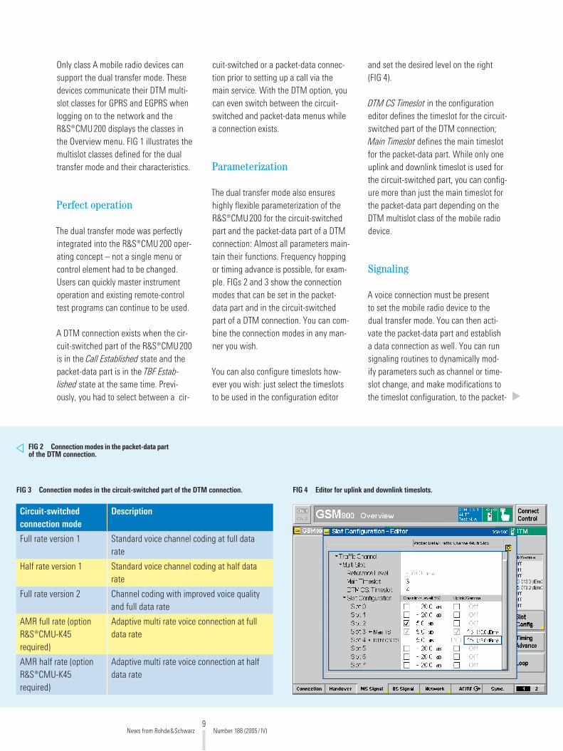
FIG 3 Connection modes in the circuit-switched part of the DTM connection. FIG 4 Editor for uplink and downlink timeslots.
Circuit-switched connection mode
Description
Full rate version 1 Standard voice channel coding at full data rate
Half rate version 1 Standard voice channel coding at half data rate
Full rate version � Channel coding with improved voice quality and full data rate
AMR full rate (option R&S®CMU-K45 required)
Adaptive multi rate voice connection at full data rate
AMR half rate (option R&S®CMU-K45 required)
Adaptive multi rate voice connection at half data rate
Only class A mobile radio devices can support the dual transfer mode. These devices communicate their DTM multi-slot classes for GPRS and EGPRS when logging on to the network and the R&S®CMU�00 displays the classes in the Overview menu. FIG 1 illustrates the multislot classes defined for the dual transfer mode and their characteristics.
Perfect operation
The dual transfer mode was perfectly integrated into the R&S®CMU�00 oper-ating concept – not a single menu or control element had to be changed. Users can quickly master instrument operation and existing remote-control test programs can continue to be used.
A DTM connection exists when the cir-cuit-switched part of the R&S®CMU�00 is in the Call Established state and the packet-data part is in the TBF Estab-lished state at the same time. Previ-ously, you had to select between a cir-
cuit-switched or a packet-data connec-tion prior to setting up a call via the main service. With the DTM option, you can even switch between the circuit-switched and packet-data menus while a connection exists.
Parameterization
The dual transfer mode also ensures highly flexible parameterization of the R&S®CMU�00 for the circuit-switched part and the packet-data part of a DTM connection: Almost all parameters main-tain their functions. Frequency hopping or timing advance is possible, for exam-ple. FIGs � and 3 show the connection modes that can be set in the packet-data part and in the circuit-switched part of a DTM connection. You can com-bine the connection modes in any man-ner you wish.
You can also configure timeslots how-ever you wish: just select the timeslots to be used in the configuration editor
and set the desired level on the right (FIG 4).
DTM CS Timeslot in the configuration editor defines the timeslot for the circuit-switched part of the DTM connection; Main Timeslot defines the main timeslot for the packet-data part. While only one uplink and downlink timeslot is used for the circuit-switched part, you can config-ure more than just the main timeslot for the packet-data part depending on the DTM multislot class of the mobile radio device.
Signaling
A voice connection must be present to set the mobile radio device to the dual transfer mode. You can then acti-vate the packet-data part and establish a data connection as well. You can run signaling routines to dynamically mod-ify parameters such as channel or time-slot change, and make modifications to the timeslot configuration, to the packet-
News from Rohde&Schwarz Number 188 (�005/ IV)

10
FIG 5 Display of message sequence with Message Viewer R&S®CMU-Z49: call setup and release of a DTM connection in the GPRS test mode.
FIG 6 Power-versus-time measurement with 8PSK modulation in the packet-data part and GMSK modulation in the circuit-switched part.
data coding scheme or to the circuit-switched traffic mode in the usual man-ner during a DTM connection.
You can use the Message Viewer R&S®CMU-Z49 to visualize the signaling process and display or analyze the con-tents of each message (FIG 5).
Transmitter measurements
Transmitter measurements are used to check the RF characteristics of the trans-mit section in the mobile radio device. Since EGPRS- and DTM-supporting mobile radio devices using modulation modes GMSK and 8PSK can transmit data on different timeslots while a DTM connection is established, you can check both modulators with only a single mea-surement. The circuit-switched timeslot of a DTM connection is always GMSK-modulated while the packet-data time-slot can also be 8PSK-modulated.
The power-versus-time measurement graphically displays the power ramp characteristic of the mobile radio device (FIG 6). Compliance with the tolerance limits defined in the GSM standard can thus be checked at a glance.
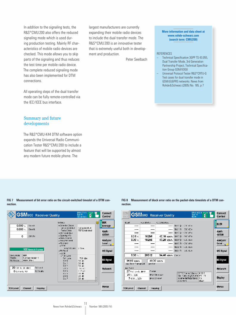
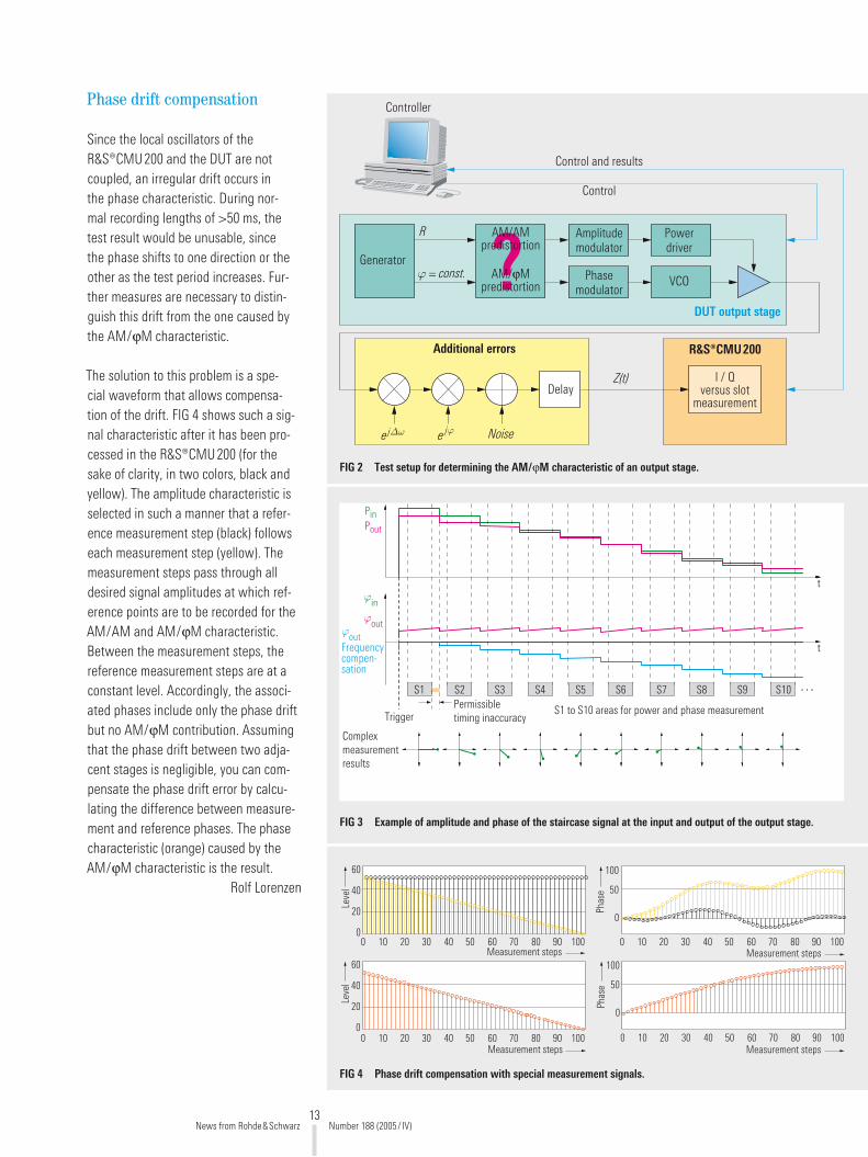
Receiver measurements
Receiver measurements check the reception quality of the mobile sta-tion receiver. The measuring principle is based on the fact that low RF-level ran-dom data is sent to the mobile radio device in the downlink. The mobile radio device then returns high RF-level data in the uplink. The R&S®CMU�00 compares sent data and received data and calcu-lates the error ratio. This calculation is based on an ideal uplink so that trans-mission errors do not occur.
The bit error ratio (BER) is measured via the circuit-switched part of the DTM
connection. In this case, random data is sent to the mobile radio device which returns the data to the R&S®CMU�00 unchanged (FIG 7).
The block error ratio (BLER) is measured on the packet-data part of the DTM con-nection. In this case, data blocks with random data are sent to the mobile radio device (FIG 8). In the uplink mode, the mobile radio device acknowledges the receipt of error-free data blocks by sending ACK/NACK messages. The R&S®CMU�00 then calculates the block error ratio (total and per slot) and the data transmission rate achieved.
Ultrafast in production
During a DTM connection, you can simultaneously run the BER and BLER measurements in the remote-control mode. This reduces the test time for a mobile radio device to a minimum.
News from Rohde&Schwarz Number 188 (�005/ IV)
MOBILE RADIO Radiocommunications testers
11
FIG 7 Measurement of bit error ratio on the circuit-switched timeslot of a DTM con-nection.
FIG 8 Measurement of block error ratio on the packet-data timeslots of a DTM con-nection.
More information and data sheet at www.rohde-schwarz.com (search term: CMU200)
REFERENCES– Technical Specification 3GPP TS 43.055,
Dual Transfer Mode, 3rd Generation Partnership Project, Technical Specifica-tion Group GSM/EDGE
– Universal Protocol Tester R&S®CRTU-G Test cases for dual transfer mode in GSM/(E)GPRS networks. News from Rohde&Schwarz (�005) No. 185, p 7
In addition to the signaling tests, the R&S®CMU�00 also offers the reduced signaling mode which is used dur-ing production testing. Mainly RF char-acteristics of mobile radio devices are checked. This mode allows you to skip parts of the signaling and thus reduces the test time per mobile radio device. The complete reduced signaling mode has also been implemented for DTM connections.
All operating steps of the dual transfer mode can be fully remote-controlled via the IEC/IEEE bus interface.
Summary and future developments
The R&S®CMU-K44 DTM software option expands the Universal Radio Communi-cation Tester R&S®CMU�00 to include a feature that will be supported by almost any modern future mobile phone. The
largest manufacturers are currently expanding their mobile radio devices to include the dual transfer mode. The R&S®CMU�00 is an innovative tester that is extremely useful both in develop-ment and production.
Peter Seelbach
News from Rohde&Schwarz Number 188 (�005/ IV)

1�
Universal Radio Communication Tester R&S®CMU200
Adjustment of polar modulators in production
Polar modulation is being used to
an increasing extent to keep costs,
size and power consumption of 2.5G
mobile radio terminals to a minimum.
However, power amplifiers in polar
modulators are operated to improve
efficiency in the nonlinear character-
istic area. This leads to distortions
and thus to an unwanted increase
in modulation errors and adjacent-
channel leakage. You can tackle
this problem by means of signal pre-
distortion with customized AM / AM
and AM / ϕM characteristics; however,
this requires the output stage charac-
teristics to be determined quickly and
effectively in production.
Principle of the polar modulator
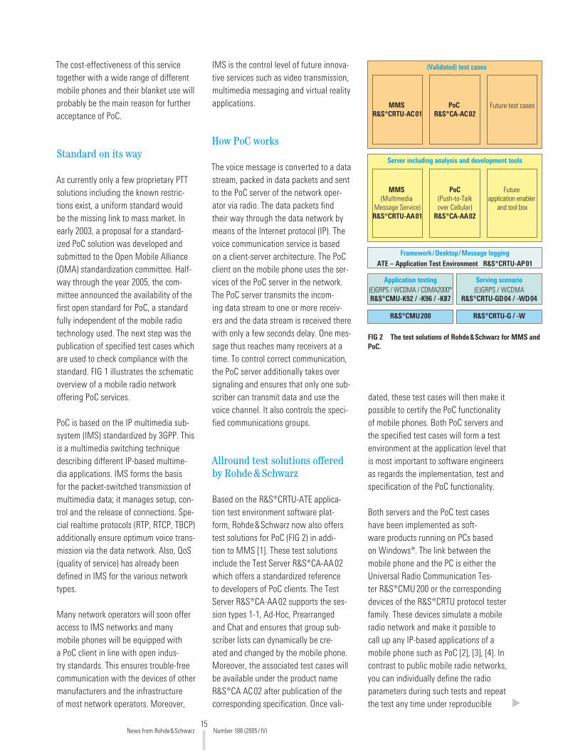
FIG 1 shows the basic design of a polar modulator. After the I/Q baseband is generated, the signal is converted to polar coordinate format with magni-tude and phase. In the case of modu-lation modes with constant envelopes (e. g. GMSK in GSM), the phase path is connected directly with the phase mod-ulator and the VCO. During simultane-ous amplitude modulation (e. g. 8PSK in EDGE), the AM path directly modulates the output stage. To compensate distor-tions, which occur due to output stage operation in the nonlinear characteristic area, predistortion is performed. In the ideal case, you can achieve a linear sig-nal chain and thus a sufficiently narrow modulation spectrum.
Determining the output stage characteristic
Even low nonlinearities of the output stage increase adjacent channel leak-age. To prevent this, you must have exact knowledge of the output stage characteristic so that correct predistor-tion is possible. Since the AM / AM and AM / ϕM characteristics generally scatter strongly in series production, you have to measure the characteristic of each output stage separately – and as quickly and reliably as possible.
I/Q versus slot measurement
The Universal Radio Communication Tes-ter R&S ® CMU�00 with Firmware Option R&S ® CMU-K48 allows you to determine the AM / AM and AM / ϕM character-istic of a power output stage. The test signal necessary for this is generated directly in the baseband of the chip-set to be tested. FIG � shows the test setup and signal flow. The signal gen-erated in the DUT passes through the entire signal chain and is analyzed in the R&S ® CMU�00. The controller performs the final comparison of the nominal test signal with the actual test signal and the calculation of the characteristic.
Signal form and processing in the R&S ® CMU200
FIG 3 shows an example of the ampli-tude and phase of the staircase signal at the input and output of the output stage. To perform an exact phase mea-surement in addition to the amplitude measurement, the R&S ® CMU�00 coher-ently synchronizes to the transmitted carrier. To do this, the mobile radio tes-ter estimates the frequency at all level stages and subsequently corrects the test signal by the average value of the estimated frequency offsets. In the ideal case, the blue phase characteristic is the result, which exhibits only the AM / ϕM influence. By complex averaging you can then determine a complex I/Q value pair for any measurement interval (Sn). These results can then be compared with the nominal values in the control-ler and further processed to obtain the actual AM / AM and AM / ϕM predistor-tion characteristic.
Conversionto magnitude
and phase
AM/AMpredistortion
AM/ Mpredistortion
RI/Q
basebandgeneration
I
Q
Amplitudemodulator
Phasemodulator
Powerdriver
VCO
Output stage
FIG 1 Basic design of a polar modulator.
News from Rohde&Schwarz Number 188 (�005/ IV)
MOBILE RADIO Radiocommunications testers
13
Phase drift compensation
Since the local oscillators of the R&S ® CMU�00 and the DUT are not coupled, an irregular drift occurs in the phase characteristic. During nor-mal recording lengths of >50 ms, the test result would be unusable, since the phase shifts to one direction or the other as the test period increases. Fur-ther measures are necessary to distin-guish this drift from the one caused by the AM / ϕM characteristic.
The solution to this problem is a spe-cial waveform that allows compensa-tion of the drift. FIG 4 shows such a sig-nal characteristic after it has been pro-cessed in the R&S ® CMU�00 (for the sake of clarity, in two colors, black and yellow). The amplitude characteristic is selected in such a manner that a refer-ence measurement step (black) follows each measurement step (yellow). The measurement steps pass through all desired signal amplitudes at which ref-erence points are to be recorded for the AM / AM and AM / ϕM characteristic. Between the measurement steps, the reference measurement steps are at a constant level. Accordingly, the associ-ated phases include only the phase drift but no AM / ϕM contribution. Assuming that the phase drift between two adja-cent stages is negligible, you can com-pensate the phase drift error by calcu-lating the difference between measure-ment and reference phases. The phase characteristic (orange) caused by the AM / ϕM characteristic is the result.
Rolf Lorenzen
?Powerdriver
Amplitudemodulator
VCOPhasemodulator
AM/AMpredistortion
Generator
R
= const.
DUT output stage
I / Qversus slot
measurement
R&S®CMU200
Z(t)
Additional errors
Delay
Noisee j e j
Controller
Control and results
Control
AM/ Mpredistortion
FIG 2 Test setup for determining the AM / ϕM characteristic of an output stage.
. . .. . .
Complexmeasurementresults
TriggerPermissibletiming inaccuracy
PinPout
S1 to S10 areas for power and phase measurement
t
t
S1 S2 S3 S4 S5 S6 S7 S8 S9 S10
outFrequencycompen-sation
out
in
FIG 3 Example of amplitude and phase of the staircase signal at the input and output of the output stage.
0 10 20 30 40 50 60 70 80 90 100
Phas
e
0 10 20 30 40 50 60 70 80 90 100
Phas
e
Measurement steps
0 10 20 30 40 50 60 70 80 90 100
0 10 20 30 40 50 60 70 80 90 100
60
40
20
0
Leve
l
100
50
0
100
50
0
Measurement steps
Measurement steps
Measurement steps
60
40
20
0
Leve
l
FIG 4 Phase drift compensation with special measurement signals.
News from Rohde&Schwarz Number 188 (�005/ IV)

14
R&S®CMU200 / R&S®CTRU-G / -W
Standardized test solutions for PoC mobile phones
PoC (push to talk over cellular), the
modern version of walkie-talkie
communication, is a very promising
new voice communications service
in mobile radio networks. Voice
messages are directly sent to one
or more predefined subscribers at a
keystroke. This bidirectional radio
service – also used as PTT (push to
talk) with only slight differences – is
based on packet-switched voice trans-
mission in GPRS, WCDMA(UMTS) or
CDMA2000® networks, for example.
This new form of group communica-
tions opens up new possibilities both
for business customers and private
users and is thus a cost-efficient alter-
native to telephony and SMS.
PoC – go ahead!
As with the classic transceiver, you just press a key on your PoC mobile phone to communicate by radio. In contrast to most conventional voice services with full-duplex transmission methods allow-ing both talking and listening at the same time, PoC is a semiduplex method: Only one subscriber at a time can talk. All others have to listen. The spatial lim-itation of current walkie-talkie commu-nications has largely been eliminated owing to roaming in mobile radio net-works. The PoC voice service works well in the complete mobile radio network, even across borders.
PoC is of interest primarily for closed user groups that have to communi-cate over large distances. In the US, for example, PTT has been used for years
to ensure interruption free communica-tion between couriers and their employ-ers. And during the world bob sleigh rac-ing championship in Oberhof, the assis-tants were also communicating via PTT. But also in private life, parties can work out a time and place to meet each other far more efficiently, faster and cost-effectively than per SMS or a number of lengthy phone calls.
Many mobile phone companies believe that PoC is going to become a real trend. Based on approx. 17 million PTT users in the US today, conservative estimates go up to more than 100 million subscribers worldwide for the year �008. The impe-tus for the target growth will largely come from the demand in the business customer segment. According to net-work providers, PoC is supposed to be more cost-efficient for users than SMS.
PoC server
FIG 1 Setup of mobile radio network with PoC service.
News from Rohde&Schwarz Number 188 (�005/ IV)
MOBILE RADIO Radiocommunications testers
15
The cost-effectiveness of this service together with a wide range of different mobile phones and their blanket use will probably be the main reason for further acceptance of PoC.
Standard on its way
As currently only a few proprietary PTT solutions including the known restric-tions exist, a uniform standard would be the missing link to mass market. In early �003, a proposal for a standard-ized PoC solution was developed and submitted to the Open Mobile Alliance (OMA) standardization committee. Half-way through the year �005, the com-mittee announced the availability of the first open standard for PoC, a standard fully independent of the mobile radio technology used. The next step was the publication of specified test cases which are used to check compliance with the standard. FIG 1 illustrates the schematic overview of a mobile radio network offering PoC services.
PoC is based on the IP multimedia sub-system (IMS) standardized by 3GPP. This is a multimedia switching technique describing different IP-based multime-dia applications. IMS forms the basis for the packet-switched transmission of multimedia data; it manages setup, con-trol and the release of connections. Spe-cial realtime protocols (RTP, RTCP, TBCP) additionally ensure optimum voice trans-mission via the data network. Also, QoS (quality of service) has already been defined in IMS for the various network types.
Many network operators will soon offer access to IMS networks and many mobile phones will be equipped with a PoC client in line with open indus-try standards. This ensures trouble-free communication with the devices of other manufacturers and the infrastructure of most network operators. Moreover,
IMS is the control level of future innova-tive services such as video transmission, multimedia messaging and virtual reality applications.
How PoC works
The voice message is converted to a data stream, packed in data packets and sent to the PoC server of the network oper-ator via radio. The data packets find their way through the data network by means of the Internet protocol (IP). The voice communication service is based on a client-server architecture. The PoC client on the mobile phone uses the ser-vices of the PoC server in the network. The PoC server transmits the incom-ing data stream to one or more receiv-ers and the data stream is received there with only a few seconds delay. One mes-sage thus reaches many receivers at a time. To control correct communication, the PoC server additionally takes over signaling and ensures that only one sub-scriber can transmit data and use the voice channel. It also controls the speci-fied communications groups.
Allround test solutions offered by Rohde&Schwarz
Based on the R&S®CRTU-ATE applica-tion test environment software plat-form, Rohde&Schwarz now also offers test solutions for PoC (FIG �) in addi-tion to MMS [1]. These test solutions include the Test Server R&S®CA-AA0� which offers a standardized reference to developers of PoC clients. The Test Server R&S®CA-AA0� supports the ses-sion types 1-1, Ad-Hoc, Prearranged and Chat and ensures that group sub-scriber lists can dynamically be cre-ated and changed by the mobile phone. Moreover, the associated test cases will be available under the product name R&S®CA AC0� after publication of the corresponding specification. Once vali-
dated, these test cases will then make it possible to certify the PoC functionality of mobile phones. Both PoC servers and the specified test cases will form a test environment at the application level that is most important to software engineers as regards the implementation, test and specification of the PoC functionality.
Both servers and the PoC test cases have been implemented as soft-ware products running on PCs based on Windows®. The link between the mobile phone and the PC is either the Universal Radio Communication Tes-ter R&S®CMU�00 or the corresponding devices of the R&S®CRTU protocol tester family. These devices simulate a mobile radio network and make it possible to call up any IP-based applications of a mobile phone such as PoC [�], [3], [4]. In contrast to public mobile radio networks, you can individually define the radio parameters during such tests and repeat the test any time under reproducible
FIG 2 The test solutions of Rohde&Schwarz for MMS and PoC.
PoC(Push-to-Talkover Cellular)
R&S®CA-AA02
MMS(Multimedia
Message Service)R&S®CRTU-AA01
Future application enabler
and tool box
Server including analysis and development tools
Application testing(E)GRPS / WCDMA / CDMA2000®R&S®CMU-K92 / -K96 / -K87
Serving scenario(E)GRPS / WCDMA
R&S®CRTU-GD04 / -WD04
R&S®CMU200 R&S®CRTU-G / -W
PoCR&S®CA-AC02
MMSR&S®CRTU-AC01
Future test cases
(Validated) test cases
ATE – Application Test Environment R&S®CRTU-AP01Framework/Desktop/Message logging
News from Rohde&Schwarz Number 188 (�005/ IV)
16
More information and data sheet at www.rohde-schwarz.com
(search term: PoC))
REFERENCE[1] R&S®CRTU-W / -G: MMS tests on
multimedia mobile phones. News from Rohde&Schwarz (�005) No. 185, pp 4–6.
[�] R&S®CMU�00: Test of CDMA�000® data applications. News from Rohde&Schwarz (�004) No. 18�, pp 11–13
[3] R&S®CMU�00: Versatile application tests in (E)GPRS mobile radio. News from Rohde&Schwarz (�004) No. 184,
pp 10–13[4] CMU goes Internet: Testing data
applications for WCDMA. News from Rohde&Schwarz (�005) No. 186,
pp 10–13
conditions. At an earlier development stage, it might still be useful to check the functionality of the mobile phone – without radiocommunications aspects
– prior to migrating the PoC client soft-ware from the PC to the mobile phone. In this case, the Rohde&Schwarz PoC server provides its services to a PoC client that is installed on a laptop, for example. The PoC communications ser-vice then runs on two connected laptops without using a mobile phone.
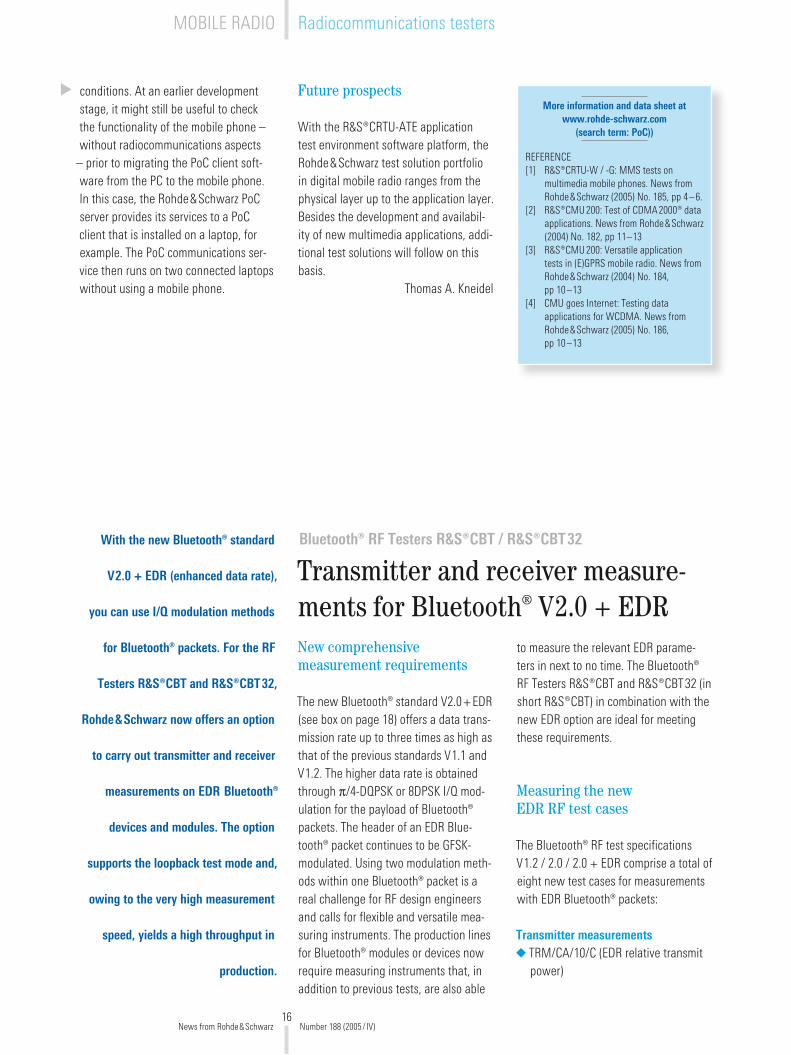
Bluetooth® RF Testers R&S®CBT / R&S®CBT32
Transmitter and receiver measure-ments for Bluetooth® V2.0 + EDR
With the new Bluetooth® standard
V2.0 + EDR (enhanced data rate),
you can use I/Q modulation methods
for Bluetooth® packets. For the RF
Testers R&S®CBT and R&S®CBT32,
Rohde&Schwarz now offers an option
to carry out transmitter and receiver
measurements on EDR Bluetooth®
devices and modules. The option
supports the loopback test mode and,
owing to the very high measurement
speed, yields a high throughput in
production.
New comprehensive measurement requirements
The new Bluetooth® standard V�.0+EDR (see box on page 18) offers a data trans-mission rate up to three times as high as that of the previous standards V1.1 and V1.�. The higher data rate is obtained through p/4-DQPSK or 8DPSK I/Q mod-ulation for the payload of Bluetooth® packets. The header of an EDR Blue-tooth® packet continues to be GFSK-modulated. Using two modulation meth-ods within one Bluetooth® packet is a real challenge for RF design engineers and calls for flexible and versatile mea-suring instruments. The production lines for Bluetooth® modules or devices now require measuring instruments that, in addition to previous tests, are also able
to measure the relevant EDR parame-ters in next to no time. The Bluetooth® RF Testers R&S®CBT and R&S®CBT3� (in short R&S®CBT) in combination with the new EDR option are ideal for meeting these requirements.
Measuring the new EDR RF test cases
The Bluetooth® RF test specifications V1.� / �.0 / �.0 + EDR comprise a total of eight new test cases for measurements with EDR Bluetooth® packets:
Transmitter measurementsTRM/CA/10/C (EDR relative transmit power)
◆
Future prospects
With the R&S®CRTU-ATE application test environment software platform, the Rohde&Schwarz test solution portfolio in digital mobile radio ranges from the physical layer up to the application layer. Besides the development and availabil-ity of new multimedia applications, addi-tional test solutions will follow on this basis.
Thomas A. Kneidel
News from Rohde&Schwarz Number 188 (�005/ IV)
MOBILE RADIO Radiocommunications testers
17
TRM/CA/11/C (EDR carrier frequency stability and modulation accuracy)TRM/CA/1�/C (EDR differential phase encoding)TRM/CA/13/C (EDR inband spurious emissions)
Receiver measurementsRCV/CA/07/C (EDR sensitivity)RCV/CA/08/C (EDR BER floor perfor-mance)RCV/CA/09/C (EDR C/I performance)RCV/CA/10/C (EDR maximum input level)
The R&S®CBT with EDR option can eval-uate seven of these new test cases. An additional external signal generator is required for measuring the C/I perfor-mance.
◆
◆
◆
◆
◆
◆
◆
New EDR transmitter measurementsTo carry out the four new EDR transmit-ter measurements, the R&S®CBT with EDR option offers four additional mea-surement menus that directly display the results stipulated by the RF test specifi-cation:
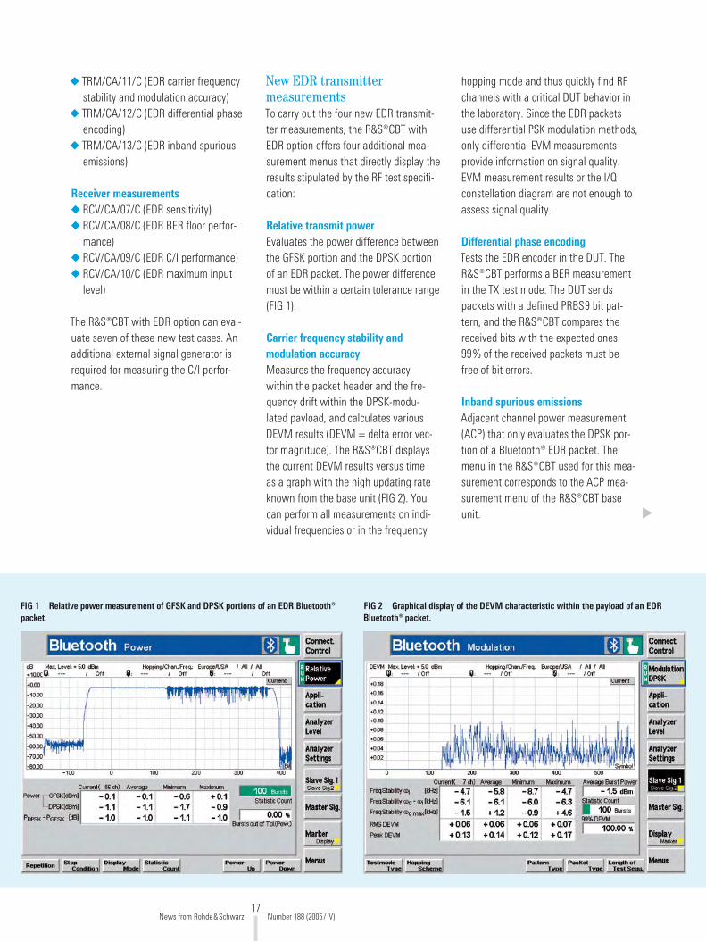
Relative transmit powerEvaluates the power difference between the GFSK portion and the DPSK portion of an EDR packet. The power difference must be within a certain tolerance range (FIG 1).
Carrier frequency stability and modulation accuracyMeasures the frequency accuracy within the packet header and the fre-quency drift within the DPSK-modu-lated payload, and calculates various DEVM results (DEVM = delta error vec-tor magnitude). The R&S®CBT displays the current DEVM results versus time as a graph with the high updating rate known from the base unit (FIG �). You can perform all measurements on indi-vidual frequencies or in the frequency
hopping mode and thus quickly find RF channels with a critical DUT behavior in the laboratory. Since the EDR packets use differential PSK modulation methods, only differential EVM measurements provide information on signal quality. EVM measurement results or the I/Q constellation diagram are not enough to assess signal quality.
Differential phase encodingTests the EDR encoder in the DUT. The R&S®CBT performs a BER measurement in the TX test mode. The DUT sends packets with a defined PRBS9 bit pat-tern, and the R&S®CBT compares the received bits with the expected ones. 99% of the received packets must be free of bit errors.
Inband spurious emissionsAdjacent channel power measurement (ACP) that only evaluates the DPSK por-tion of a Bluetooth® EDR packet. The menu in the R&S®CBT used for this mea-surement corresponds to the ACP mea-surement menu of the R&S®CBT base unit.
FIG 1 Relative power measurement of GFSK and DPSK portions of an EDR Bluetooth® packet.
FIG 2 Graphical display of the DEVM characteristic within the payload of an EDR Bluetooth® packet.
News from Rohde&Schwarz Number 188 (�005/ IV)

18
The R&S®CBT performs all EDR trans-mitter measurements with the very high measurement speed already known from the base unit. This not only allows fast working in the laboratory but is also par-ticularly beneficial in production, since the testing time (and thus the costs for testing) can be reduced to a minimum.
Loopback test mode for EDR receiver measurements
To carry out the new EDR receiver measurements, the R&S®CBT sup-ports the loopback test mode in accor-dance with Bluetooth® specification V�.0 + EDR. Proprietary solutions of the various chip manufacturers are no lon-ger needed to evaluate the receiver sen-sitivity. The BER measurement menu of the R&S®CBT known from the base unit additionally allows you to set the new EDR packet types in combination with the EDR option. Moreover, the R&S®CBT
also includes the new dirty transmit-ter for EDR packets in accordance with the Bluetooth® RF test specification and offers various setting options for the dif-ferent parameters of the dirty transmit-ter. This is particularly beneficial for lab-oratory tests.
R&S® CBTGo supports work in the laboratory
R&S®CBTGo is PC application soft-ware allowing remote control of the R&S®CBT and R&S®CBT3�. You can thus very easily configure any desired test sequence. Running a test sequence gen-erates a test report that can be stored or whose results can be processed in a spreadsheet. R&S®CBTGo supports the Bluetooth® test cases that can be per-formed with the R&S®CBT and addition-ally offers further interesting features for working in the laboratory. The soft-ware can, for example, automatically
evaluate the measurement results of all Bluetooth® channels and can graphi-cally display their characteristic in a test report. R&S®CBTGo can be downloaded free of charge from the Rohde&Schwarz website.
Dieter Mahnken
More information and data sheet at www.rohde-schwarz.com
(search term: CBT or CBTGo)
The new Bluetooth® standard dis-tinguishes between basic rate and enhanced data rate packets. Basic rate packets are already known from the standards V1.1 and V1.�. The addi-tional EDR packets use the same packet header as basic rate packets (GFSK modulation) but transmit the payload by using DPSK modulation (p/4-DQPSK or 8DPSK). The Bluetooth® transmitter must therefore be able to switch over from GFSK to DPSK modulation within 5 µs.
The DPSK modulation of the EDR pack-ets yields a data transmission rate that is up to three times as high as that of basic rate packets. The Bluetooth® tech-nology thus opens up new applications,
e.g. the uncompressed transmission of CD audio signals. When EDR packets are used for all applications that do not require higher data rates, smaller packet
Packet headerGFSK
PayloadDPSK
Packet headerGFSK
Guardtime
DPSKsynchr.
sequence
PayloadGFSK
5 µs 11 µs
Basic rate Bluetooth® packet
Enhanced data rate Bluetooth® packet
lengths are obtained. The power con-sumption is thus reduced, which is par-ticularly important for battery-powered devices (e.g. Bluetooth® headsets).
The new Bluetooth® standard V2.0 + EDR at a glance
News from Rohde&Schwarz Number 188 (�005/ IV)
MOBILE RADIO Radiocommunications testers
19
Vector Signal Generator R&S®SMU200A
Signals for testing multicarrier power amplifiers
Featuring excellent ACLR values,
an RF bandwidth of 80 MHz and a
high output level, the Vector Signal
Generator R&S®SMU200A is an
unrivaled multicarrier signal source.
New trend: multicarrier base stations
The growing number of voice and data services plus new standards such as 3GPP FDD or CDMA�000® led to a dense occupation of available frequency resources – compared with the initial phase of mobile radio.
Due to technical and cost-saving rea-sons the number of single-carrier base stations is limited. Hence, multicar-rier base stations with only one power amplifier must accommodate several frequency channels. The linearity and intermodulation requirements placed on these amplifiers are very high, especially for 3GPP FDD or CDMA�000®.
The well-known multicarrier continuous wave option of the Vector Signal Gener-ator R&S®SMU�00A allows you to gen-erate a multicarrier CW signal with user-definable carrier spacing and maximally 819� unmodulated carriers. Now, the new multicarrier feature enables you to configure modulated carrier signals as well. A powerful yet easy-to-oper-ate menu provides a multicarrier signal with up to 3� carriers and 80 MHz band-width. Using this signal, you can per-form various transmitter and receiver tests specifically tailored to multicarrier transmission (e.g. in accordance with 3GPP TS�5.141).
Complex signals – easy handling
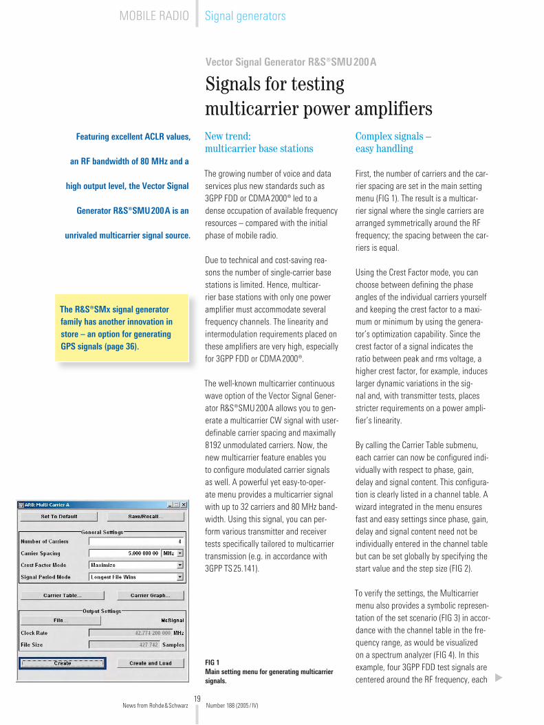
First, the number of carriers and the car-rier spacing are set in the main setting menu (FIG 1). The result is a multicar-rier signal where the single carriers are arranged symmetrically around the RF frequency; the spacing between the car-riers is equal.
Using the Crest Factor mode, you can choose between defining the phase angles of the individual carriers yourself and keeping the crest factor to a maxi-mum or minimum by using the genera-tor’s optimization capability. Since the crest factor of a signal indicates the ratio between peak and rms voltage, a higher crest factor, for example, induces larger dynamic variations in the sig-nal and, with transmitter tests, places stricter requirements on a power ampli-fier’s linearity.
By calling the Carrier Table submenu, each carrier can now be configured indi-vidually with respect to phase, gain, delay and signal content. This configura-tion is clearly listed in a channel table. A wizard integrated in the menu ensures fast and easy settings since phase, gain, delay and signal content need not be individually entered in the channel table but can be set globally by specifying the start value and the step size (FIG �).
To verify the settings, the Multicarrier menu also provides a symbolic represen-tation of the set scenario (FIG 3) in accor-dance with the channel table in the fre-quency range, as would be visualized on a spectrum analyzer (FIG 4). In this example, four 3GPP FDD test signals are centered around the RF frequency, each
FIG 1 Main setting menu for generating multicarrier signals.
The R&S®SMx signal generator family has another innovation in store – an option for generating GPS signals (page 36).
News from Rohde&Schwarz Number 188 (�005/ IV)
MOBILE RADIO Signal generators

�0
FIG 2 The Carrier Table Assistant submenu and the channel table derived from it.
attenuated by � dB relative to the others. The result of 68 dB for ACLR is far better than the 50 dB limit specified by 3GPP in TS�5.141 for spurious emissions.
Owing to the high level accuracy of internal signal processing in the R&S®SMU�00A, the level differences of the individual carriers with regard to each other may be 30 dB to 40 dB at an acceptable error vector magnitude (EVM), if required by the test scenario. The delay of the carrier signals with respect to each other can be set to 1 ns exactly. In the TS�5.141, for example, the downlink test models of the 3GPP standards specify that the individual car-riers, each shifted by one fifth of a time-slot duration, be added together.
New: interface for waveform files
All internally or externally generated waveform files can be used as input sig-nal sources for the individual carriers. The R&S WinIQSIM™ Windows® soft-ware, for example, allows you to gen-erate various waveforms yourself or import signals from other mathemati-cal programs such as MATLAB® using R&S IQWizard™ [*]. Data can be loaded to the generator via the USB or IEC/IEEE bus interface.
What’s new is that the software mod-ules integrated in the R&S®SMU�00A can now also generate waveform files for the 3GPP FDD and CDMA�000® stan-dards; these files already include a com-pletely modulated, i.e. pulse-shaped, waveform (FIG 5 top, Generate Wave-form File). These files can be directly entered on the Multicarrier list as the input data sources. Thus, a single signal generator can generate a user-config-urable multicarrier test signal for these standards without requiring further devices or external PCs.
FIG 3 Visualized channel table: four 3GPP test signals, each with a level difference of 2 dB relative to the others.
FIG 4 As a result, the multicarrier signal is made up of four 3GPP signals (test model 1) that are arranged on adja-cent carriers at 5 MHz spacing.
-30-40-50-60-70-80-90-100-110
Ref -20 dBm *Att 5 dB
*RBW 30 kHz*VBW 300 kHz*SWT 5 s
A
Center 2.14 GHz 4.06 MHz/ Span 40.6 MHz
1 RM*CLRWR
NOR
Standard: WCDMA 3GPP FWD Adjacent Channel Lower -68.49 dBTx Channels Upper -68.30 dB
Ch1 (Ref) -16.85 dBm Alternate ChannelCh2 -18.86 dBm Lower -69.53 dBCh3 -20.87 dBm Upper -67.25 dBCh4 -22.74 dBm
Total -13.27 dBm
POS -19.965 dBm
News from Rohde&Schwarz Number 188 (�005/ IV)
MOBILE RADIO Signal generators
�1
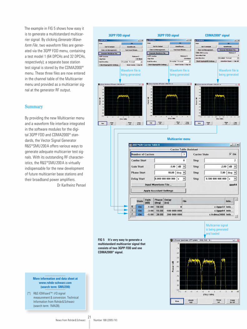
The example in FIG 5 shows how easy it is to generate a multistandard multicar-rier signal: By clicking Generate Wave-form File, two waveform files are gener-ated via the 3GPP FDD menu, containing a test model 1 (64 DPCHs and 3� DPCHs, respectively); a separate base station test signal is stored by the CDMA�000® menu. These three files are now entered in the channel table of the Multicarrier menu and provided as a multicarrier sig-nal at the generator RF output.
Summary
By providing the new Multicarrier menu and a waveform file interface integrated in the software modules for the digi-tal 3GPP FDD and CDMA�000® stan-dards, the Vector Signal Generator R&S®SMU�00A offers various ways to generate adequate multicarrier test sig-nals. With its outstanding RF character-istics, the R&S®SMU�00A is virtually indispensable for the new development of future multicarrier base stations and their broadband power amplifiers.
Dr Karlheinz Pensel
More information and data sheet at www.rohde-schwarz.com
(search term: SMU200)
[*] R&S IQWizard™: I/Q signal measurement & conversion. Technical Information from Rohde&Schwarz (search term: 1MA�8).
3GPP FDD signal 3GPP FDD signal CDMA2000® signal
Multicarrier menu
Waveform file is being generated
Waveform file is being generated
Waveform file is being generated
Multicarrier signal is being generated and loaded
FIG 5 It’s very easy to generate a multistandard multicarrier signal that consists of two 3GPP FDD and one CDMA2000® signal.
News from Rohde&Schwarz Number 188 (�005/ IV)

��
WLAN Protocol Tester R&S®PTW70
Multimode protocol analysis in WLANs
You can find IEEE 802.11-based
WLANs in all types of environments:
in wireless home networks but also
in company and campus networks
or in giant hotspots for providing
coverage for complete cities. As a
result, the requirements placed on
protocol testers are quite complex and
demanding.
FIG 1 The new WLAN Protocol Tester R&S®PTW70 provides all required conformance test functions. But that’s not all it can do.
Designed for high performance
At first glance, the R&S®PTW70 is quite simple in design (FIG 1). The tester does not even have a display since one would be of little use for graphically display-ing the results of complex protocol anal-ysis anyway. The actual strength of the new protocol tester is its convenient and extremely powerful control software which can be installed on any PC run-ning on Windows®. The link between the controller and the protocol tester is established via a LAN. This concept is ideal since it allows the highly versa-tile use of the protocol tester via remote control.
From a classic protocol tester to a general-purpose instrument
The main task of a protocol tester is to check DUTs for compliance with stan-dard specifications (conformance tests). To ensure a uniform test procedure cov-ering all relevant scenarios, the stan-dardization bodies usually specify pro-tocol conformance tests. This is mostly done in the TTCN language (TTCN = tree and tabular combined notation), which was specially developed for this pur-pose and is used, for example, for the 3G standards and Bluetooth®.
4445�/5
News from Rohde&Schwarz Number 188 (�005/ IV)
Protocol testersWPAN / WLAN / WWAN

�3
The IEEE 80�.11a/b/g standards, how-ever, do not use this language. Instead, golden device tests are defined to ensure interoperability. During these tests, a DUT is checked for correct oper-ation in conjunction with several other reference units.
The drawbacks of this indeed very prag-matic approach soon become evident. The selected reference units have a sig-nificant influence on the result. A pos-sible malfunction does not give many clues to the actual source of error since it could have also been caused by one of the reference units. Many scenarios cannot even be tested with this method. There are no invalid behavior tests at all. During these tests, the response of the DUT to malfunctions of the counterpart is examined more closely.
The Protocol Tester R&S®PTW70 of course provides all conformance test functions. But Rohde&Schwarz is known for offering devices that far exceed stan-dard requirements: A classic protocol tester would probably not be accepted in this difficult market. The new protocol tester was meant to go far beyond these standard requirements. In addition to the defined test cases, it was supposed to be flexible enough to handle a wide variety of tasks in non-conformance test-ing. This included not only multimode capabilities, but also the capability to adapt the test sequence as quickly as possible and without any special knowl-edge of the TTCN language, for example. The R&S®PTW70 meets these demand-ing requirements.
Multimode capability – versatility required
Multimode capability means that all important associated standards and extensions are supported by the R&S®PTW70. This includes IEEE 80�.11a/b/g in the ISM and
IEEE 80�.11 is an IEEE-specified fam-ily of standards for WLANS. The 80�.11a /b/g standards are widely used. The 11b and 11g standards oper-ate in the license-free ISM band at �.4 GHz, 11a in the U-NII band at 5 GHz. The 11b standard uses DSSS modu-lation, whereas 11a and 11g operate with OFDM and 5� subcarriers that are modulated with BPSK, QPSK, 16QAM or 64QAM depending on the data rate. The 11g standard is backward-compat-ible with 11b. The 11b standard allows gross data rates up to 11 Mbit/s, 11a and 11g up to 54 Mbit/s.
U-NII bands but also the Japan band. The protocol tester can be operated as an access point and station. Switchover is dynamic, i.e. the stack is not reloaded.
The R&S®PTW70 has two main operat-ing modes: the monitor mode for passive communication sniffing on the air inter-face and the active mode for triggering the communication stack. You can run the protocol tester in both modes at the same time. This allows direct control at any layer (LLC, MAC, PHY). These char-acteristics make the R&S®PTW70 ideal for a variety of applications, e.g. retrans-mission tests, invalid behavior tests and stress tests.
The R&S®PTW70 offers calibrated level measurements, a settable output level (–30 dBm to +10 dBm) and packet error ratio measurements. The high time res-olution of 50 ns for recording protocol messages makes detailed problem anal-ysis easy. You can send IP payload files through the protocol tester directly via the network interface.
Numerous expansions are available, e.g. 11e (quality of service enhance-ments) and 11i (security enhance-ments). Especially 11i uses encryption technologies other than WEP, which was originally used and was less safe.
Interestingly, the very similar Euro-pean ETSI standard HiperLAN/� basi-cally specifies many of the subse-quent 80�.11 expansions. However, HiperLAN/� could not match the 80�.11 standard, which was promoted much faster.
Simple operation despite maximum flexibility
Even setting up a small WLAN home network can present problems, because so many parameters have to be defined. Imagine how complex a user interface for a protocol tester must be where prac-tically every parameter down to the indi-vidual bits of a layer-1 message can be modified. Rohde&Schwarz solved this problem by using a hierarchical script user interface (FIG �).
In the R&S®PTW70, scripts are not edited in text form but are created by means of a special graphical user inter-face. The structure is deliberately kept simple: You can program whatever you want without having to know a script language or higher programming lan-guage. Even so, this graphical user inter-face contains very complex functions, i.e. the timeout-controlled reception of mes-sages, the evaluation of individual mes-sage fields and the generation of report files.
The IEEE 802.11 standard
News from Rohde&Schwarz Number 188 (�005/ IV)
�4
Scripts run directly on the protocol tes-ter and are therefore independent of the network connection or the load on the controller. A script is downloaded to the protocol tester and then compiled so quickly that you may think that the script was executed immediately. Together with the convenient test step editor, scripts can thus be modified and exe-cuted again within seconds.
Uncompromising online data analysis
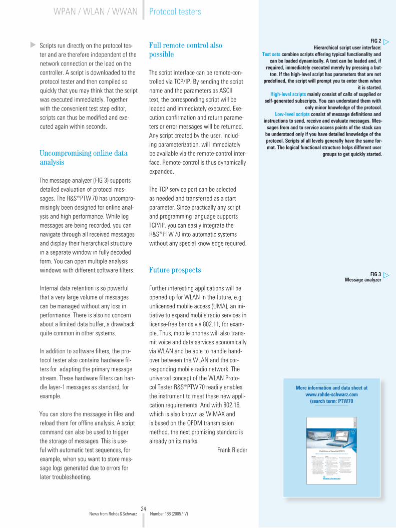
The message analyzer (FIG 3) supports detailed evaluation of protocol mes-sages. The R&S®PTW70 has uncompro-misingly been designed for online anal-ysis and high performance. While log messages are being recorded, you can navigate through all received messages and display their hierarchical structure in a separate window in fully decoded form. You can open multiple analysis windows with different software filters.
Internal data retention is so powerful that a very large volume of messages can be managed without any loss in performance. There is also no concern about a limited data buffer, a drawback quite common in other systems.
In addition to software filters, the pro-tocol tester also contains hardware fil-ters for adapting the primary message stream. These hardware filters can han-dle layer-1 messages as standard, for example.
You can store the messages in files and reload them for offline analysis. A script command can also be used to trigger the storage of messages. This is use-ful with automatic test sequences, for example, when you want to store mes-sage logs generated due to errors for later troubleshooting.
Full remote control also possible
The script interface can be remote-con-trolled via TCP/IP. By sending the script name and the parameters as ASCII text, the corresponding script will be loaded and immediately executed. Exe-cution confirmation and return parame-ters or error messages will be returned. Any script created by the user, includ-ing parameterization, will immediately be available via the remote-control inter-face. Remote-control is thus dynamically expanded.
The TCP service port can be selected as needed and transferred as a start parameter. Since practically any script and programming language supports TCP/IP, you can easily integrate the R&S®PTW70 into automatic systems without any special knowledge required.
Future prospects
Further interesting applications will be opened up for WLAN in the future, e.g. unlicensed mobile access (UMA), an ini-tiative to expand mobile radio services in license-free bands via 80�.11, for exam-ple. Thus, mobile phones will also trans-mit voice and data services economically via WLAN and be able to handle hand-over between the WLAN and the cor-responding mobile radio network. The universal concept of the WLAN Proto-col Tester R&S®PTW70 readily enables the instrument to meet these new appli-cation requirements. And with 80�.16, which is also known as WiMAX and is based on the OFDM transmission method, the next promising standard is already on its marks.
Frank Rieder
More information and data sheet at www.rohde-schwarz.com
(search term: PTW70
WLAN Protocol Tester ¸PTW 70cation
ApplicationsDevelopment –The ¸ PTW70 is anindispensable error diagnostics tool forwireless LAN system components fromchip set to complete infrastructureIntegration – By accommodating wireless LAN software and hardware modules, the ¸ PTW 70 can be used to evaluate how different system components interact and to test cross-technology compatibility
design, the ¸ PTW70 allows theperformance and quality features ofwireless LAN system components to be
FeaturesAnalyzer mode – The IEEE 802.11 reference model of the ¸ PTW 70simulates a wireless LAN access point or a stationSniffer or monitor mode – The ¸ PTW 70 records data communications in a wireless LAN cellThe multi-choice operating concept features graphical and programmable user interfaces Online analysis tools provide the userwith reliable data exactly when neededHardware-based timers and realtime processing make it possible to analyze protocol sequences in detail in all operating modes
The measurement unit is detached from the controller and can be remotely driven from different workstations
given measurement task – from the single-channel model to versions networking several ¸ PTW 70testers
Its powerful hardware platform makesthe tester a future-proof investment
Version01.00
November2003
Dat
a sh
eet
FIG 2 Hierarchical script user interface:
Test sets combine scripts offering typical functionality and can be loaded dynamically. A test can be loaded and, if
required, immediately executed merely by pressing a but-ton. If the high-level script has parameters that are not
predefined, the script will prompt you to enter them when it is started.
High-level scripts mainly consist of calls of supplied or self-generated subscripts. You can understand them with
only minor knowledge of the protocol.Low-level scripts consist of message definitions and
instructions to send, receive and evaluate messages. Mes-sages from and to service access points of the stack can
be understood only if you have detailed knowledge of the protocol. Scripts of all levels generally have the same for-mat. The logical functional structure helps different user
groups to get quickly started.
FIG 3 Message analyzer
News from Rohde&Schwarz Number 188 (�005/ IV)
WPAN / WLAN / WWAN Protocol testers

�5
Test set Low-level scripts High-level script Test step editor
Analyzer window Message sequence chart Scan windowDecoder window
News from Rohde&Schwarz Number 188 (�005/ IV)
�6
Vector Network Analyzer R&S®ZVA
High-end network analyzer – future-proof and extremely fast
The new R&S®ZVA generation of
high-end network analyzers offers
high measurement speed, maximum
dynamic range and extremely high
versatility and accuracy – ideal
prerequisites for present and future
measurement tasks. On top of this,
the user benefits from an easy and
intuitive operating concept.
Sophisticated hardware concept
The high end Network Analyzer R&S®ZVA (FIG 1) is available in two mod-els up to 8 GHz and �4 GHz with two or four test ports each. Like the R&S®ZVR predecessor model, the R&S®ZVA employs the tried-and-tested fundamen-tal mixing concept, which ensures maxi-mum sensitivity and dynamic range. The analyzer features extremely fast syn-thesizers, which make for minimum measurement times. Each test port is equipped with a measurement receiver and a reference receiver, and a sepa-rate generator is provided for each pair
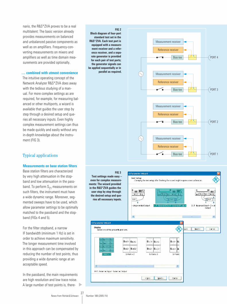
of test ports; the generator signals can be applied sequentially or in parallel as required (FIG �). This enables parallel measurements on DUTs.
Multitalent opening up unique opportunities for designers
Unparalleled versatility …New technologies and increasingly shorter innovation cycles mean that designers in development labs are faced with continuously changing require-ments. A scenario like this calls for highly versatile test equipment that can be used for a variety of DUTs. In this sce-
44410/10
FIG 1 Superior RF performance combined with versatile use and extendability – these are essential characteristics of the Vector Network Analyzer R&S®ZVA.
News from Rohde&Schwarz Number 188 (�005/ IV)
Network analyzersGENERAL PURPOSE
�7
PORT 4
Measurement receiver
Reference receiver
Bias-tee
PORT 3
Measurement receiver
Reference receiver
Bias-tee
PORT 2
Measurement receiver
Reference receiver
Bias-tee
PORT 1
Measurement receiver
Reference receiver
Bias-tee
FIG 2 Block diagram of four-port
standard test set in the R&S®ZVA. Each test port is
equipped with a measure-ment receiver and a refer-ence receiver, and a sepa-rate generator is provided for each pair of test ports; the generator signals can
be applied sequentially or in parallel as required.
nario, the R&S®ZVA proves to be a real multitalent: The basic version already provides measurements on balanced and unbalanced passive components as well as on amplifiers. Frequency-con-verting measurements on mixers and amplifiers as well as time domain mea-surements are provided optionally.
… combined with utmost convenienceThe intuitive operating concept of the Network Analyzer R&S®ZVA does away with the tedious studying of a man-ual. For more complex settings as are required, for example, for measuring bal-anced or other multiports, a wizard is available that guides the user step by step through a desired setup and que-ries all necessary inputs. Even highly complex measurement settings can thus be made quickly and easily without any in-depth knowledge about the instru-ment (FIG 3).
Typical applications
Measurements on base station filtersBase station filters are characterized by very high attenuation in the stop-band and low attenuation in the pass-band. To perform S�1 measurements on such filters, the instrument must have a wide dynamic range. Moreover, seg-mented sweeps have to be used, which allow parameter settings to be optimally matched to the passband and the stop-band (FIGs 4 and 5).
For the filter stopband, a narrow IF bandwidth (minimum 1 Hz) is set in order to achieve maximum sensitivity. The longer measurement time involved in this approach can be compensated by reducing the number of test points, thus providing a wide dynamic range at an acceptable speed.
In the passband, the main requirements are high resolution and low trace noise. A large number of test points is, there-
FIG 3 Test settings made easy –
even for complex measure-ments: The wizard provided in the R&S®ZVA guides the
user step by step through the desired setup and que-
ries all necessary inputs.
News from Rohde&Schwarz Number 188 (�005/ IV)
�8
fore, selected for this range in order to enable an accurate analysis of the filter ripple – which is the ratio of the maxi-mum to the minimum power level in the passband. To prevent the receiver sec-tion of the analyzer from being over-driven because of the low filter atten-uation, an output power of –10 dBm is selected, for example (FIG 4).
Characterization of amplifiersThe R&S®ZVA offers a wide range of amplifier measurements. To measure the transmission characteristics of an amplifier with high accuracy and with-out interruption, it is desirable to use the widest possible level range without hav-ing to switch any attenuators. Featuring electronic level switching over a range of typically 50 dB, the R&S®ZVA is ide-ally suited for measuring the transmis-sion and compression characteristics of amplifiers (FIG 6).
Measuring the small signal behavior sometimes calls for extremely small lev-els. Optional mechanical attenuators are available to reduce the analyzer output level to <–100 dBm. Measuring com-pression, by contrast, calls for output levels as high as possible; the R&S®ZVA offers +15 dBm.
Measuring active DUTs requires DC volt-age, which can be fed at the bias-tee inputs on the R&S®ZVA rear panel. The DC voltage is applied to the DUT via the analyzer‘s inner conductor. The DC inputs on the R&S®ZVA make it possi-ble to measure the supply voltage or the current proportional to this voltage, from which the power added efficiency (PAE), i.e. the ratio of output minus input power to DC power of the amplifier, is determined.
To ensure highly accurate amplifier mea-surements, the analyzer‘s output power is calibrated, which also eliminates the effects of the test setup. This is done by means of an R&S®NRP power sen-
sor, which is connected to the R&S®ZVA and controlled via its USB interface. By means of this power sensor, the R&S®ZVA calibrates the generator ver-sus level or frequency. Calibration can be carried out in iterative steps or down to a predefined minimum level tolerance.
Intermodulation measurements on amplifiersThe R&S®ZVA four-port model comes with two internal generators. These can generate a two-tone signal, which is required for intermodulation mea-surements. An external generator is not needed (FIG 7). The low phase noise of the R&S®ZVA‘s internal generators and the very good power-handling capabil-ity of its receivers are optimum prerequi-sites for measuring high intercept points.
Hot S-parameter measurements on power amplifiersTo characterize a power amplifier, its output matching (S��) must be measured under real conditions, i.e. under full load, which is known as hot S-parameter mea-surement. This is the only way to opti-mally match an amplifier to the load at its output. The problem encountered in this measurement is that the high output signal of the amplifier is superimposed on the signal generated by the ana-lyzer at test port �. The problem is solved by introducing a small frequency off-set between the signal at the amplifier output and the signal generated by the analyzer for measuring S��. This, how-ever, requires very high receiver selectiv-ity as well as robust level control – fea-tures which are of course provided by the R&S®ZVA.
Frequency-converting measurements on mixersThe R&S®ZVA analyzer concept features independent synthesizers. This is nec-essary for performing measurements on mixers and frequency converters, as it allows the generators and receivers to sweep at different frequencies. The LO
signal for the mixer can be supplied by an external generator or by the second generator provided in the R&S®ZVA four-port model (FIG 8).
Intermodulation measurements on mix-ers can be performed using an external generator, which is controlled via the analyzer‘s LAN or IEC/IEEE bus interface. Mixers are mainly characterized by their conversion loss, matching, group delay, isolation, compression and intermodula-tion – the R&S®ZVA measures all these quantities and provides a straightfor-ward overview of results (FIG 9).
Optimized production sequences
The principal requirement in production is high throughput. Whether high pro-duction throughput can be achieved depends on the speed of the measur-ing instruments and, in automated sequences, on the time required for data transfer to the controller.
Record holder in speedThe R&S®ZVA sets new standards in measurement speed since, due to its fast synthesizers, it requires less than 5 ms for a frequency sweep over �01 test points. In the CW sweep mode, a mea-surement time of less than 3.5 µs per test point can be achieved. This makes the R&S®ZVA the fastest network ana-lyzer currently available on the market.
To minimize measurement time, the IF bandwidth should be as large as pos-sible. At the same time, dynamic range should not be unduly reduced and trace noise should be kept to a minimum. The R&S®ZVA‘s is optimally suited for this as it features an excellent dynamic range of typically 135 dB between test ports, which is extended up to 150 dB with direct receiver access (option), and trace noise as low as typically 0.0008 dB at an IF bandwidth of 1 kHz.
News from Rohde&Schwarz Number 188 (�005/ IV)
GENERAL PURPOSE Network analyzers
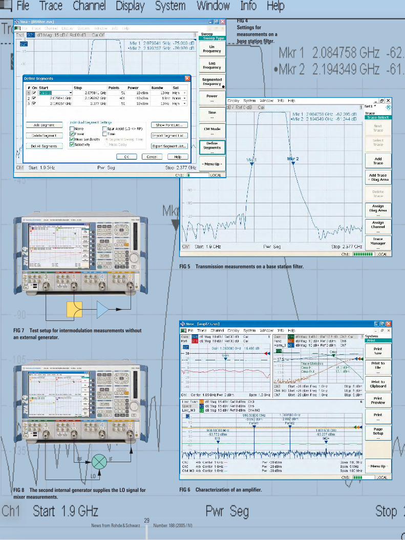
�9
FIG 4 Settings for measurements on a base station filter.
FIG 5 Transmission measurements on a base station filter.
FIG 6 Characterization of an amplifier.
FIG 7 Test setup for intermodulation measurements without an external generator.
RF IF
LO
FIG 8 The second internal generator supplies the LO signal for mixer measurements.
News from Rohde&Schwarz Number 188 (�005/ IV)

30
Measurement speed can be further optimized by using segmented sweeps, where test parameters such as the IF bandwidth, number of test points and the generator level can be defined sep-arately for each segment. Measure-ments can thus be focused on segments of interest, and carried out with the dynamic range and frequency resolution optimally adapted for each segment.
Data transfer in virtually no timeThe R&S®ZVA hardware concept makes it possible to transfer data measured during the first sweep to the controller already during the second sweep via the analyzer‘s IEC/IEEE bus or LAN interface. This means that data transfer time is practically insignificant, which substan-tially cuts down on measurement time.
To further speed up automated test sequences, the R&S®ZVA provides chan-nel bits at its trigger I/O port. The chan-nel bits synchronize the DUT with the network analyzer, allowing limit values to be queried or external hardware to be controlled.
Fast switching between instrument setupsPreviously, when measuring several DUTs, the required instrument set-ups had to be loaded from hard disk each time the DUT was changed. The R&S®ZVA can load various setups including calibration data into RAM and switch between these setups in less than 10 ms. To select the desired setup window, simply use the mouse in man-ual production applications; in auto-mated test sequences, switchover is made by IEC/IEEE bus or LAN control (FIG 10).
True parallel measurementsThe R&S®ZVA hardware concept allows true parallel measurements since the analyzer‘s internal generators can be switched to all test ports at the same time. For example, the R&S®ZVA four-
port model can analyze two two-port DUTs in parallel or measure the reflec-tion of four one-port DUTs at its four ports in parallel.
Direct generator and receiver access
For some applications, external ampli-fiers, filters or attenuators have to be included in the test setup. This is pos-sible by using the “Direct Generator /Receiver Access“ option. This option in conjunction with the generator and receiver attenuator options turn the R&S®ZVA into an instrument that pro-vides utmost flexibility in creating test setups.
Another positive effect of the direct access mode is that dynamic range increases to 150 dB (at 1 Hz IF band-width) since the internal couplers are bypassed. This is of interest when mea-suring high-blocking filters, for example.
Numerous calibration techniquesIt goes without saying that a high-end network analyzer should provide a large number of calibration techniques. This is ensured by the R&S®ZVA hardware concept, which features a measurement and a reference receiver for each test port. This means that, in addition to clas-sic TOSM calibration, modern 7-term cal-ibration techniques can be used. These include TOM, TRL/LRL, TRM and TNA, some of which are of interest in particu-lar for carrying out calibration in test fix-tures or on wafers.
Manual calibration techniques are, however, time-consuming and error-prone especially where multiports are concerned. To solve this problem, Rohde&Schwarz offers an automatic calibration unit that comes in various models (FIG 11). Controlled by the net-work analyzer, the calibration unit per-forms complete four-port calibration
in less than 30 seconds, for example. Apart from saving time, automatic cal-ibration units offer the advantage that they have to be connected only once to carry out a complete calibration. This means less wear to the connectors and thus an extended life. And, last but not least, automatic calibration practically excludes operator errors.
Summary
Superior RF performance combined with versatile use and extendability – these are the current requirements in the development and production of state-of-the-art components and modules. The R&S®ZVA from Rohde&Schwarz per-fectly meets these requirements and, moreover, is easy to operate.
Andreas Henkel
More information, product brochure and specifications at
www.rohde-schwarz.com (search term: ZVA)
Version
01.00
September
2005
Vector Network Analyzer ¸ZVAHigh-end network analyzer up to 8 GHz /24 GHz with two or four test ports
Prod
uct b
roch
ure
High output power typ. >15 dBmWide dynamic range typ. >135 dBHigh measurement speed <3.5 µs per test point
Balanced measurementsLinear and nonlinear amplifi er and mixer measurements
Versatile calibration techniques TOSM, TRL/LRL, TOM, TRM, TNAAutomatic calibration unit
Spec
ifica
tions
Version
01.00
September
2005
Vector Network Analyzer ¸ZVASpecifications
News from Rohde&Schwarz Number 188 (�005/ IV)
GENERAL PURPOSE Network analyzers

31
FIG 9 Characterization of a mixer (con-version gain, matching, isolation
and intermodulation).
FIG 10 You can switch between setups in no time – simply by means of the mouse or via the IEC/IEEE bus.
Condensed data of the R&S®ZVANumber of test ports � or 4Frequency range 300 kHz to 8 GHz (R&S®ZVA8), 10 MHz to �4 GHz (R&S®ZVA�4)Measurement time per test point <3.5 µsMeasurement time (�01 test points) 4.5 msData transfer time (�01 test points) Via IEC/IEEE bus <�.9 ms Via VX11 (LAN with 100 Mbit/s) <1.3 ms Via RSIB (LAN with 100 Mbit/s) <0.7 msSwitching time Between channels <1 ms Between instrument setups <10 msDynamic range at 10 Hz measurement bandwidth Between test ports >130 dB, typ. 135 dB With direct receiver access typ. 145 dBOutput level at test port >+13 dBm, typ. +15 dBmLevel sweep range >40 dB, typ. 50 dBIF bandwidths 1 Hz to 1 MHzNumber of channels, diagrams, traces >100 each (depending on available RAM capacity)Number of test points per trace � to �0001Operating system Windows XP Embedded
FIG 11 The automatic Calibration Unit R&S®ZV-Z51 saves time and prevents errors.
4440
5/1
News from Rohde&Schwarz Number 188 (�005/ IV)
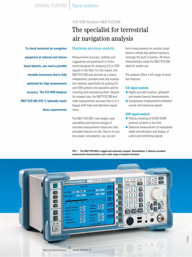
3�
ILS/VOR Analyzer R&S®EVS300
The specialist for terrestrial air navigation analysis
To check terrestrial air navigation
equipment at national and interna-
tional airports, you need a portable,
versatile instrument that is fully
optimized for high measurement
accuracy. The ILS/VOR Analyzer
R&S®EVS300 (FIG 1) optimally meets
these requirements.
FIG 1 The R&S®EVS300 is rugged and extremely compact. Nevertheless, it features excellent measurement characteristics and a wide range of analysis functions.
Maximum precision analysis
Measurement accuracy, mobility and ruggedness are paramount in instru-ments designed for analyzing ILS or VOR signals in the field. For this reason, the R&S®EVS300 was devised as a mains-independent, portable level and modula-tion analyzer specifically for putting ILS and VOR systems into operation and for checking and maintaining them. Despite its compact size, the R&S®EVS300 pro-vides measurement accuracy that is in a league with high-end laboratory equip-ment.
The R&S®EVS300’s low weight, easy operability and internal storage of recorded measurement values are indis-pensable features on site. Due to its very low power consumption, you can per-
form measurements on outdoor instal-lations a whole day without having to recharge the built-in battery. All these characteristics make the R&S®EVS300 ideal for mobile use.
The analyzer offers a full range of excel-lent features:
ILS signal analysisHighly accurate localizer, glidepath and marker beacon measurementsComparative measurements between course and clearance signals
VOR signal analysisPrecise checking of CVOR/DVOR antenna systems in the fieldSelective measurement of modulation depth and deviation and display of useful and interfering signals
◆
◆
◆
◆
44�8
5/3
News from Rohde&Schwarz Number 188 (�005/ IV)
GENERAL PURPOSE Signal analyzers

33
Further special characteristicsContinuous frequency range from 70 MHz to 350 MHzOptional fast frequency scan across user-selectable frequency ranges with spectrum display and marker functionsVery high dynamic range and high immunity to interference due to steep-edge preselector filters in the ILS/VOR and MB ranges; switchable preamplifier and high-level mixerRugged and compact design for use in the fieldBattery-supplied operating time of 8 h to 10 h during continuous measure-ment
General characteristicsHigh-contrast TFT color display (16.4 cm / 6.4")Wide operating temperature range from –10°C to +55°CLow weight (5.7 kg)High mechanical resistance in accor-dance with MIL-STD-810D and DIN IEC 68Self-test (BITE)LAN and RS-�3�-C interface for remote control of all functions and for measurement data outputUSB connector to easily export data and perform software updates
Predestined for challenging measurement tasks
Although ILS transmitter systems include integrated monitoring functions, they require regular measuring and maintainance using independent equip-ment as an integral part of modern air traffic control. Especially the dynamic measurement of ILS signals by test vehi-cles along the runways is a key task of the institutions responsible for air traffic safety (FIGs � and 3).
The R&S®EVS300 is predestined to meet these challenges, considering
◆
◆
◆
◆
◆
◆
◆
◆
◆
◆
◆
◆
FIG 2 The measurement
of ILS signals along the runways is
performed by means of test vehicles, with the R&S®EVS300 as the core component.
FIG 3 ILS systems of the
III b category require high-precision
measurement instru-ments for checking
the DDM values.
to save time when performing measure-ments on runways, since no air traffic is allowed on the runway during these measurements.
Time is money – this is also true espe-cially for measurement flights. Equipped with a second optional measurement channel, the R&S®EVS300 can simulta-neously perform two independent mea-surement tasks on any frequencies, e.g. measuring the localizer and glideslope signals during the approach for landing, or checking two VOR stations.
its numerous functions such as inte-grated recording of all relevant measure-ment parameters including GPS posi-tion data, optional external triggering and graphical display of the DDM char-acteristics. Used in conjunction with the R&S®HE108 antenna, which was spe-cially designed for such applications, the R&S®EVS300 is the key component of the measurement system. Its unique dual-channel signal processing capabil-ity allows simultaneous and indepen-dent measuring of course and clearance characteristics. The R&S®EVS300‘s high measurement speed and quick data stor-age ability plus the two channels help
4439
9/6
4439
9/5
News from Rohde&Schwarz Number 188 (�005/ IV)
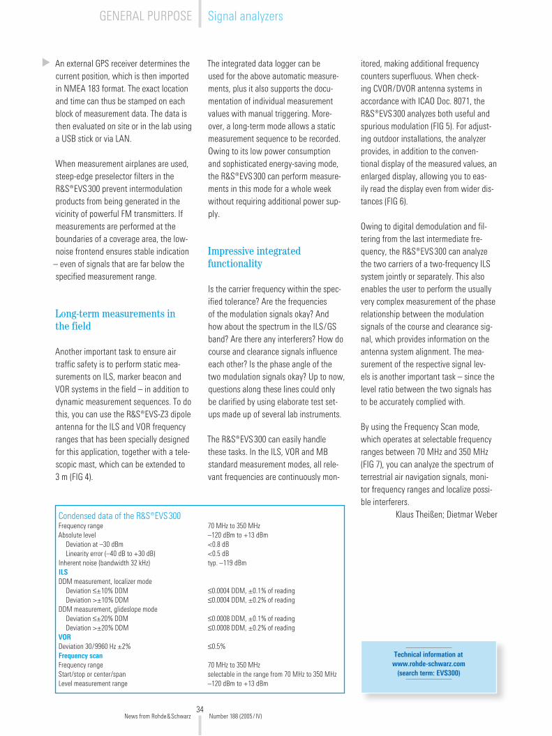
34
An external GPS receiver determines the current position, which is then imported in NMEA 183 format. The exact location and time can thus be stamped on each block of measurement data. The data is then evaluated on site or in the lab using a USB stick or via LAN.
When measurement airplanes are used, steep-edge preselector filters in the R&S®EVS300 prevent intermodulation products from being generated in the vicinity of powerful FM transmitters. If measurements are performed at the boundaries of a coverage area, the low-noise frontend ensures stable indication
– even of signals that are far below the specified measurement range.
Long-term measurements in the field
Another important task to ensure air traffic safety is to perform static mea-surements on ILS, marker beacon and VOR systems in the field – in addition to dynamic measurement sequences. To do this, you can use the R&S®EVS-Z3 dipole antenna for the ILS and VOR frequency ranges that has been specially designed for this application, together with a tele-scopic mast, which can be extended to 3 m (FIG 4).
The integrated data logger can be used for the above automatic measure-ments, plus it also supports the docu-mentation of individual measurement values with manual triggering. More-over, a long-term mode allows a static measurement sequence to be recorded. Owing to its low power consumption and sophisticated energy-saving mode, the R&S®EVS300 can perform measure-ments in this mode for a whole week without requiring additional power sup-ply.
Impressive integrated functionality
Is the carrier frequency within the spec-ified tolerance? Are the frequencies of the modulation signals okay? And how about the spectrum in the ILS/GS band? Are there any interferers? How do course and clearance signals influence each other? Is the phase angle of the two modulation signals okay? Up to now, questions along these lines could only be clarified by using elaborate test set-ups made up of several lab instruments.
The R&S®EVS300 can easily handle these tasks. In the ILS, VOR and MB standard measurement modes, all rele-vant frequencies are continuously mon-
itored, making additional frequency counters superfluous. When check-ing CVOR/DVOR antenna systems in accordance with ICAO Doc. 8071, the R&S®EVS300 analyzes both useful and spurious modulation (FIG 5). For adjust-ing outdoor installations, the analyzer provides, in addition to the conven-tional display of the measured values, an enlarged display, allowing you to eas-ily read the display even from wider dis-tances (FIG 6).
Owing to digital demodulation and fil-tering from the last intermediate fre-quency, the R&S®EVS300 can analyze the two carriers of a two-frequency ILS system jointly or separately. This also enables the user to perform the usually very complex measurement of the phase relationship between the modulation signals of the course and clearance sig-nal, which provides information on the antenna system alignment. The mea-surement of the respective signal lev-els is another important task – since the level ratio between the two signals has to be accurately complied with.
By using the Frequency Scan mode, which operates at selectable frequency ranges between 70 MHz and 350 MHz (FIG 7), you can analyze the spectrum of terrestrial air navigation signals, moni-tor frequency ranges and localize possi-ble interferers.
Klaus Theißen; Dietmar WeberCondensed data of the R&S®EVS300Frequency range 70 MHz to 350 MHzAbsolute level –1�0 dBm to +13 dBm Deviation at –30 dBm <0.8 dB Linearity error (–40 dB to +30 dB) <0.5 dBInherent noise (bandwidth 3� kHz) typ. –119 dBmILSDDM measurement, localizer mode Deviation ≤±10% DDM ≤0.0004 DDM, ±0.1% of reading Deviation >±10% DDM ≤0.0004 DDM, ±0.�% of readingDDM measurement, glideslope mode Deviation ≤±�0% DDM ≤0.0008 DDM, ±0.1% of reading Deviation >±�0% DDM ≤0.0008 DDM, ±0.�% of readingVORDeviation 30/9960 Hz ±�% ≤0.5%Frequency scanFrequency range 70 MHz to 350 MHzStart/stop or center/span selectable in the range from 70 MHz to 350 MHzLevel measurement range –1�0 dBm to +13 dBm
Technical information at www.rohde-schwarz.com
(search term: EVS300)
News from Rohde&Schwarz Number 188 (�005/ IV)
GENERAL PURPOSE Signal analyzers
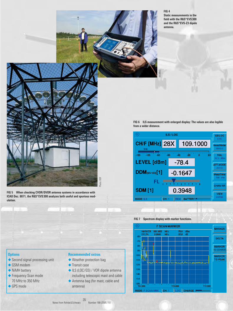
35
OptionsSecond signal processing unitGSM modemNiMH batteryFrequency Scan mode 70 MHz to 350 MHzGPS mode
◆
◆
◆
◆
◆
Recommended extrasWeather protection bagTransit caseILS (LOC/GS) / VOR dipole antenna including telescopic mast and cableAntenna bag (for mast, cable and antenna)
◆
◆
◆
◆
FIG 4 Static measurements in the field with the R&S®EVS300 and the R&S®EVS-Z3 dipole antenna.
FIG 5 When checking CVOR/DVOR antenna systems in accordance with ICAO Doc. 8071, the R&S®EVS300 analyzes both useful and spurious mod-ulation.
FIG 6 ILS measurement with enlarged display: The values are also legible from a wider distance.
FIG 7 Spectrum display with marker functions.
Phot
o: D
SF
4439
9/�
News from Rohde&Schwarz Number 188 (�005/ IV)
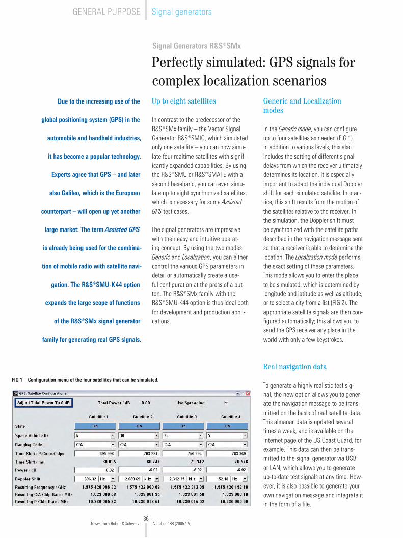
36
Signal Generators R&S®SMx
Perfectly simulated: GPS signals for complex localization scenariosUp to eight satellites
In contrast to the predecessor of the R&S®SMx family – the Vector Signal Generator R&S®SMIQ, which simulated only one satellite – you can now simu-late four realtime satellites with signif-icantly expanded capabilities. By using the R&S®SMU or R&S®SMATE with a second baseband, you can even simu-late up to eight synchronized satellites, which is necessary for some Assisted GPS test cases.
The signal generators are impressive with their easy and intuitive operat-ing concept. By using the two modes Generic and Localization, you can either control the various GPS parameters in detail or automatically create a use-ful configuration at the press of a but-ton. The R&S®SMx family with the R&S®SMU-K44 option is thus ideal both for development and production appli-cations.
Generic and Localization modes
In the Generic mode, you can configure up to four satellites as needed (FIG 1). In addition to various levels, this also includes the setting of different signal delays from which the receiver ultimately determines its location. It is especially important to adapt the individual Doppler shift for each simulated satellite. In prac-tice, this shift results from the motion of the satellites relative to the receiver. In the simulation, the Doppler shift must be synchronized with the satellite paths described in the navigation message sent so that a receiver is able to determine the location. The Localization mode performs the exact setting of these parameters. This mode allows you to enter the place to be simulated, which is determined by longitude and latitude as well as altitude, or to select a city from a list (FIG �). The appropriate satellite signals are then con-figured automatically; this allows you to send the GPS receiver any place in the world with only a few keystrokes.
Real navigation data
To generate a highly realistic test sig-nal, the new option allows you to gener-ate the navigation message to be trans-mitted on the basis of real satellite data. This almanac data is updated several times a week, and is available on the Internet page of the US Coast Guard, for example. This data can then be trans-mitted to the signal generator via USB or LAN, which allows you to generate up-to-date test signals at any time. How-ever, it is also possible to generate your own navigation message and integrate it in the form of a file.
FIG 1 Configuration menu of the four satellites that can be simulated.
Due to the increasing use of the
global positioning system (GPS) in the
automobile and handheld industries,
it has become a popular technology.
Experts agree that GPS – and later
also Galileo, which is the European
counterpart – will open up yet another
large market: The term Assisted GPS
is already being used for the combina-
tion of mobile radio with satellite navi-
gation. The R&S®SMU-K44 option
expands the large scope of functions
of the R&S®SMx signal generator
family for generating real GPS signals.
News from Rohde&Schwarz Number 188 (�005/ IV)
GENERAL PURPOSE Signal generators
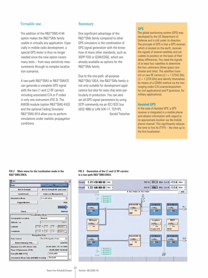
37
Versatile use
The addition of the R&S®SMU-K44 option makes the R&S®SMx family usable in virtually any application. Espe-cially in mobile radio development, a special GPS tester is thus no longer needed since the new option covers many tests – from easy sensitivity mea-surements through to complex localiza-tion scenarios.
A two-path R&S®SMU or R&S®SMATE can generate a complete GPS signal with the two L1 and L� RF carriers including associated C/A or P codes in only one instrument (FIG 3). The AWGN module (option R&S®SMU-K6�) and the optional Fading Simulator R&S®SMU-B14 allow you to perform simulations under realistic propagation conditions.
FIG 3 Generation of the L1 and L2 RF carriers in a two-path R&S®SMU200A.
FIG 2 Main menu for the Localization mode in the R&S®SMU200A.
Summary
One significant advantage of the R&S®SMx family compared to other GPS simulators is the combination of GPS signal generation with the know-how of many other standards, such as 3GPP FDD or GSM/EDGE, which are already available as options for the R&S®SMx family.
Due to the one-path, all-purpose R&S®SMJ100A, the R&S®SMx family is not only suitable for development appli-cations but also for easy chip tests par-ticularly in production. You can also set all GPS signal parameters by using SCPI commands via an IEC/IEEE bus (IEEE 488) or LAN (VXI-11, TCP/IP).
Gerald Tietscher
GPSThe global positioning system (GPS) was developed by the US Department of Defense and is still under its direction. The principle of GPS is that a GPS receiver, which is located on the earth, receives the signals of several satellites and cal-culates its position on the basis of their delay differences. You need the signals of at least four satellites to determine the four unknowns (three space coor-dinates and time). The satellites trans-mit on two RF carriers (L1 = 1.5754� GHz, L� = 1.��76 GHz) and identify themselves by means of a CDMA method via the two ranging codes C/A (coarse/acquisition, for civil applications) and P (precision, for military applications).
Assisted GPSIn the case of Assisted GPS, a GPS receiver is integrated in a mobile phone and obtains information with regard to its approximate location via the mobile phone channel. This significantly reduces the time to first fix (TTFF) – the time up to the first localization.
News from Rohde&Schwarz Number 188 (�005/ IV)
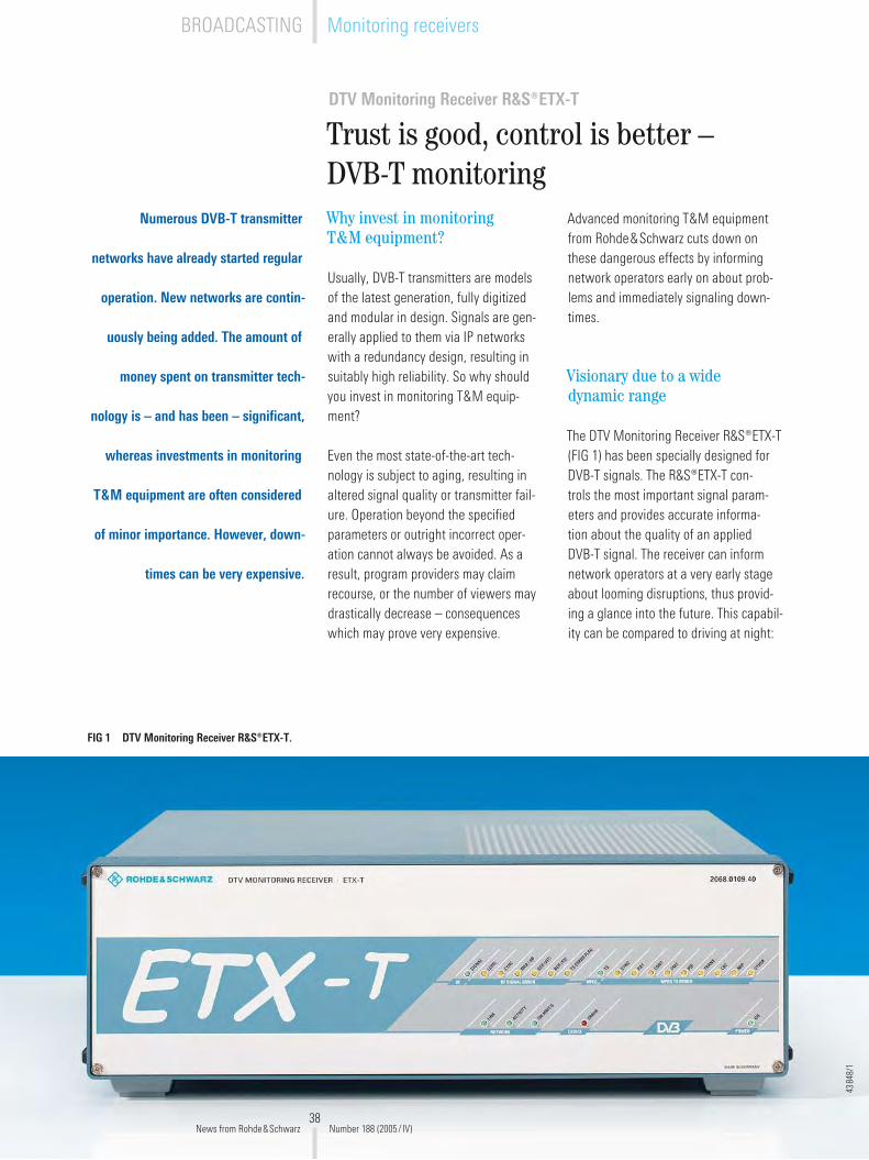
38
DTV Monitoring Receiver R&S®ETX-T
Trust is good, control is better – DVB-T monitoring
Numerous DVB-T transmitter
networks have already started regular
operation. New networks are contin-
uously being added. The amount of
money spent on transmitter tech-
nology is – and has been – significant,
whereas investments in monitoring
T&M equipment are often considered
of minor importance. However, down-
times can be very expensive.
Why invest in monitoring T&M equipment?
Usually, DVB-T transmitters are models of the latest generation, fully digitized and modular in design. Signals are gen-erally applied to them via IP networks with a redundancy design, resulting in suitably high reliability. So why should you invest in monitoring T&M equip-ment?
Even the most state-of-the-art tech-nology is subject to aging, resulting in altered signal quality or transmitter fail-ure. Operation beyond the specified parameters or outright incorrect oper-ation cannot always be avoided. As a result, program providers may claim recourse, or the number of viewers may drastically decrease – consequences which may prove very expensive.
Advanced monitoring T&M equipment from Rohde&Schwarz cuts down on these dangerous effects by informing network operators early on about prob-lems and immediately signaling down-times.
Visionary due to a wide dynamic range
The DTV Monitoring Receiver R&S®ETX-T (FIG 1) has been specially designed for DVB-T signals. The R&S®ETX-T con-trols the most important signal param-eters and provides accurate informa-tion about the quality of an applied DVB-T signal. The receiver can inform network operators at a very early stage about looming disruptions, thus provid-ing a glance into the future. This capabil-ity can be compared to driving at night:
FIG 1 DTV Monitoring Receiver R&S®ETX-T.
4384
8/1
News from Rohde&Schwarz Number 188 (�005/ IV)
Monitoring receiversBROADCASTING

39
The brighter the headlights of a car, the better the driver’s vision – and the ear-lier possible obstacles can be detected. The R&S®ETX-T has a similar concept: Due to its wide dynamic range, infinites-imal changes in the monitored transmit-ter parameters can be detected at a very early stage. Thus, conclusions can be drawn. This helps to save time and take appropriate countermeasures.
Versatile applications
Unlike simple receive modules, the R&S®ETX-T provides you with a wide variety of measurements and functions, reflecting its versatile applications. The R&S®ETX-T primarily records all major RF parameters of an emitted DVB-T signal on the transmitter and internally stores the measurement data. This makes it easier for transmitter operators to fur-nish proof of quality of service (QoS), for example. The receiver outputs alarm messages if one or several selected parameters exceed the specified limits.
Both its measurement capabilities and its previously mentioned dynamic range match those of a high-end TV test receiver. And since the R&S®ETX-T can be remote-controlled, problems can be narrowed down from anywhere; there is no need for a measurement technician to visit the site with additional measur-ing equipment.
The monitoring receiver is equipped with a selective RF input section. An inter-nal preamplifier and optional SAW fil-ters ensure excellent receive character-istics; used with a common receiving antenna, these characteristics make the R&S®ETX-T also ideal for use as a mon-itoring receiver within a coverage area. A combined monitoring and measure-ment receiver in a single instrument, the R&S®ETX-T is a favorably priced solution for current and future tasks.
Setup details
The incoming DVB-T signal passes through an input attenuator (which can be switched manually or automatically) before it is applied to the receive sec-tion (FIG �). The receive section is nar-rowband; using SAW filters, selectivity can be optionally increased, for example if the receiver is not to be used directly on the transmitter. The OFDM demodu-lator provides the analysis section with the data required for evaluation; the demodulated MPEG-� transport stream is applied at the TS-ASI output.
The R&S®ETX-T can be upgraded with an MPEG-� decoder, which is option-ally supplied with or without audio and video outputs. Both versions allow easy MPEG-� monitoring of the main param-eters in accordance with TR 101 �90. Each decoder has two external inputs. You can switch between these inputs and the internally demodulated trans-port stream for MPEG-� monitoring. You can thus also monitor the transport streams applied at the transmitter.
Operation and communications
The receiver is controlled and operated only via its LAN interface (TCP/IP), so the front panel is very straightforward. LEDs indicate the operating state and the LAN connection and signal alarm messages.
The R&S®ETX-T can be accessed in two different ways. An Internet-capable ter-minal such as a PC, notebook or PDA is required for direct access. You don‘t need special software; a common web browser is sufficient. You have to log on to the receiver, specifying your user name and password. The receiver man-ages access and user rights, which can be assigned as required: from the right to see just a few parameters through to full administration rights. The user inter-face is automatically adapted to reflect the rights assigned.
But the receiver can also be accessed via the standardized SNMP protocol, which allows you to easily integrate the receiver into management programs. An SNMP agent integrated into the
Internet / LAN
MPEG-2 TS ASI 1
DVB-T test receiverInput attenuator and preamplifier
Option R&S®ETX-B2 / option R&S®ETX-B3MPEG-2 realtime monitoring
MPEG-2 TS ASI
Front panel with LEDs
MPEG-2 TS ASI 2
DVB-T signal (RF)
VideoAudio
MPEG-2 TSASI
Controller
Communicationsserver
SNMP agent
HTTP server
TCP/IP (10/100Base T)
FIG 2 R&S®ETX-T block diagram.
News from Rohde&Schwarz Number 188 (�005/ IV)
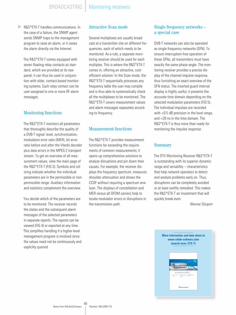
40
R&S®ETX-T handles communications. In the case of a failure, the SNMP agent sends SNMP traps to the management program to raise an alarm, or it raises the alarm directly via the Internet.
The R&S®ETX-T comes equipped with seven floating relay contacts as stan-dard, which are provided at its rear panel; it can thus be used in conjunc-tion with older, contact-based monitor-ing systems. Each relay contact can be user-assigned to one or more RF alarm messages.
Monitoring functions
The R&S®ETX-T monitors all parameters that thoroughly describe the quality of a DVB-T signal: level, synchronization, modulation error ratio (MER), bit error ratio before and after the Viterbi decoder plus data errors in the MPEG-� transport stream. To get an overview of all mea-surement values, view the main page of the R&S®ETX-T (FIG 3). Symbols and col-oring indicate whether the individual parameters are in the permissible or non-permissible range. Auxiliary information and statistics complement the overview.
You decide which of the parameters are to be monitored. The receiver records the states and the subsequent alarm messages of the selected parameters in separate reports. The reports can be viewed (FIG 4) or exported at any time. This simplifies handling if a higher-level management program is involved since the values need not be continuously and explicitly queried.
Attractive Scan mode
Several multiplexes are usually broad-cast at a transmitter site on different fre-quencies, each of which needs to be monitored. As a rule, a separate moni-toring receiver should be used for each multiplex. This is where the R&S®ETX-T comes in, offering an attractive, cost-efficient solution: In the Scan mode, the R&S®ETX-T sequentially processes any frequency table the user may compile and is thus able to systematically check all the multiplexes to be monitored. The R&S®ETX-T covers measurement values and alarm messages separately accord-ing to frequency.
Measurement functions
The R&S®ETX-T provides measurement functions far exceeding the require-ments of common measurements; it opens up comprehensive solutions to analyze disruptions and pin down their causes. For example, the receiver dis-plays the frequency spectrum, measures shoulder attenuation and shows the CCDF without requiring a spectrum ana-lyzer. The displays of constellation and MER versus all OFDM carriers help to locate modulator errors or disruptions in the transmission path.
More information and data sheet at www.rohde-schwarz.com
(search term: ETX-T)
Cost-effective DVB-T monitoring receiverFrequency scan mode
Realtime remote monitoringEasy integration into SNMP manage-ment systemsHigh reliability
Optional realtime MPEG2 analysisRemote control via SNMP, HTTP or COM server
DTV Monitoring Receiver R&S ETX-TRealtime monitoring, demodulation and analysis of DVB-T signals via LAN
Single frequency networks – a special case
DVB-T networks can also be operated as single frequency networks (SFN). To ensure interruption-free operation of these SFNs, all transmitters must have exactly the same phase angle. The mon-itoring receiver provides a precise dis-play of the channel impulse response, thus furnishing an exact overview of the SFN status. The inserted guard interval display is highly useful; it presents the accurate time domain depending on the selected modulation parameters (FIG 5). The individual impulses are recorded with <0.5 dB precision in the level range, and <�0 ns in the time domain. The R&S®ETX-T is thus more than ready for monitoring the impulse response.
Summary
The DTV Monitoring Receiver R&S®ETX-T is outstanding with its superior dynamic range and versatility – characteristics that help network operators to detect and analyze problems early on. Thus, disruptions can be completely avoided or at least swiftly remedied. This makes the R&S®ETX-T an investment that will quickly break even.
Werner Dürport
News from Rohde&Schwarz Number 188 (�005/ IV)
BROADCASTING Monitoring receivers
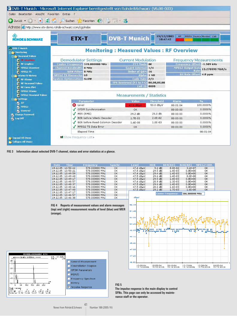
41
FIG 3 Information about selected DVB-T channel, status and error statistics at a glance.
FIG 5 The impulse response is the main display to control SFNs. This page can only be accessed by mainte-nance staff or the operator.
FIG 4 Reports of measurement values and alarm messages (top) and (right) measurement results of level (blue) and MER (orange).
News from Rohde&Schwarz Number 188 (�005/ IV)

4�
Generating and analyzing transport streams for DVB-H
The DVB-H standard has been
specified for supplying broadband
data services to mobile terminals. In
contrast to DVB-T, the emphasis is
on robust transmission, support of
mobile reception and saving energy
in terminals. Rohde&Schwarz
provides new software and options
for generating and analyzing DVB-H
transport streams.
Key features of DVB-H
Transport streams for DVB-H are based on the structure of DVB-T transport streams, and may include services that are compatible with both DVB-T and DVB-H. The IP/MAC notification table (INT) signals whether a DVB-H service is included in the transport stream.
In DVB-H, the IP data (payload) belong-ing to a service is transmitted via multi-protocol encapsulation (MPE), a method that describes the transport of IP data in MPEG-� data streams. A typical appli-cation is the transmission of video data with low resolution (e.g. H.�64-coded). The IP data is divided into blocks of data called sections for transport. A high level of error protection is ensured on the transmission path by means of special error protection data, which is transmit-ted in its own sections together with the payload (MPE-FEC). The service provider defines the proportion of protection data to payload.
The introduction of DVB-H also included the introduction of time slicing, where the data of a DVB-H service is trans-mitted in bursts. The service provider defines the distances between the bursts and the length of each burst within a range specified by the standard. Time slicing reduces energy consump-tion in the receiver since the receiver can switch off its receiving unit between bursts.
Transport streams from library or by means of software
To test DVB-H-compatible terminals, you need transport streams with the above characteristics. Rohde&Schwarz meets this need by offering a DVD with a large collection of transport streams with con-tents coded in different ways and a wide variety of parameters for time slicing [*].
However, some applications require cus-tomer-specific transport streams, such as in the following cases:
When special contents are usedWhen customized DVB-H parameters are appliedWhen DVB-H services are combined with special DVB-T programs, etc
To enable you to make your own trans-port streams, Rohde&Schwarz offers the Advanced Stream Combiner R&S®DV-ASC software option. With just a few keystrokes, you can gener-ate DVB-H-compatible transport streams with your own parameters. R&S®DV-ASC is an expansion of the tried-and-tested Stream Combiner R&S®DVG-B1 for gen-erating MPEG-� transport streams for various transmission methods such as DVB-T, DVB-S, DVB-C and ATSC.
The DVB-H interface in R&S®DV-ASC is intended for IP data saved in files. You can use your own IP data or select from a large collection which comes with the DVB-H Stream Library DVD 1). The soft-ware automatically inserts or calculates all DVB-H characteristics. FIG 1 shows the user interface of the Advanced Stream Combiner software; the screen-shot in the foreground shows the win-dow for setting time slicing and FEC parameters.
◆
◆
◆
1) The replay of these contents is only possible if the DVB-H Stream Library option is enabled on the instruments used.
More information and a demo version of the R&S®DV-ASC software at
www.rohde-schwarz.com (search terms: DVM/DV-ASC/DV-DVBH)
[*] The ”DVB-H Stream Library R&S®DV-DVBH“ DVD is available from any Rohde&Schwarz office.
News from Rohde&Schwarz Number 188 (�005/ IV)
BROADCASTING Test methods

43
The transport streams that have been generated by using the software and also the transport streams of the ready-made library can be replayed with the generators in the Broadcast Test System R&S®SFU and the Digital Video Mea-surement System R&S®DVM400, as well as with the DTV Recorder Generator R&S®DVRG.
Analysis functions
The measurement functions of the R&S®DVM family have also been expanded to enable you to analyze all DVB-H-specific features:
Correct signaling and integration into the transport streamInterpretation of the INTDetailed syntax analysis und interpre-tation of the MPE sectionsEvaluation of error protectionTime slicing measurement with graph-ical display (FIG �)Data extraction and video content decoding (if codec is known)
All functions mentioned above are avail-able with the Data Broadcast Analy-sis R&S®DVM-K11 option for all instru-ments of the R&S®DVM family. The base units can already recognize DVB-H ser-vices and measure the data rate (PID level). You can use the In-Depth Anal-ysis R&S®DVM-K10 option to interpret the INT.
Thomas Tobergte
◆
◆
◆
◆
◆
◆
FIG 1 Setting of the DVB-H parameters with the Advanced Stream Combiner R&S®DV-ASC software option.
FIG 2 Display of time slicing and associated measurement value for a burst as well as display of the decoded picture.
News from Rohde&Schwarz Number 188 (�005/ IV)

44
Control Unit R&S NetCCU®800
Common control unit for FM and TV transmitters
FIG 1 The Control Unit R&S NetCCU® 800 can be used both in the TV and FM transmitters of the R&S®Nx8000 family.
The Control Unit R&S NetCCU®800
is the distributing center and user
interface for the new successful
R&S®Nx8000 transmitter platform. Switching center for two transmitter families
The Control Unit R&S NetCCU®800 (FIG 1) is included as a common distrib-uting center both in the new generation of R&S®NH/NV8�00 TV transmitters [1] and in the new family of VHF FM Trans-mitters R&S®NR8�00 [�]. For network operators, this has the advantage of low operation and training costs as well as simplified logistics with regard to stock-keeping of spare parts. For the first time, the control concept and user interfaces in TV and FM transmitters are uniform. This also simplifies their integration into network management systems and facil-itates the setup and putting them into operation, plus reduces maintenance and service costs.
Innovative control concept
A transmitter system mainly consists of an exciter, amplifier, cooling system and transmitter control unit. Depend-ing on the output power or redundancy concept, these components are pres-ent in multiples. The central control unit’s (CCU) task is to display the sys-tem parameters, to monitor them and to perform redundancy switching in the event of an error. To maximize the per-formance, the R&S NetCCU®800 is con-nected with the exciters via Ethernet and with the amplifiers via a CAN bus (FIG �).
Remote control and local operation
The color display (1/4 VGA) and the keys on the front panel are used for local operation of the transmitters. The
More information at www.rohde-schwarz.com (search term: NetCCU800)
REFERENCES[1] UHF TV Transmitters R&S®NH/NV8�00:
Air-cooled transmitters for the medium-power segment. News from Rohde&Schwarz (�005) No. 185, pp 40–4�
[�] Family of VHF FM Transmitters R&S®NR8�00: Compact, air-cooled transmitters for �.5 kW to 30 kW. News from Rohde&Schwarz (�005) No. 186, pp 44–45
[3] Transmitter Control Unit R&S NetCCU® 700: All-purpose instru-ment with integrated DVB-T receiver module. News from Rohde&Schwarz (�005) No. 185, pp 34–37
44316/1
News from Rohde&Schwarz Number 188 (�005/ IV)
BROADCASTING TV transmitters
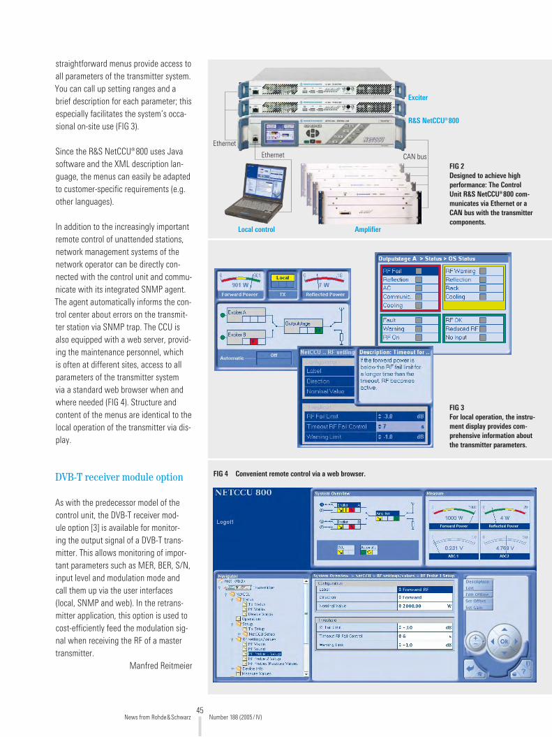
45
straightforward menus provide access to all parameters of the transmitter system. You can call up setting ranges and a brief description for each parameter; this especially facilitates the system‘s occa-sional on-site use (FIG 3).
Since the R&S NetCCU®800 uses Java software and the XML description lan-guage, the menus can easily be adapted to customer-specific requirements (e.g. other languages).
In addition to the increasingly important remote control of unattended stations, network management systems of the network operator can be directly con-nected with the control unit and commu-nicate with its integrated SNMP agent. The agent automatically informs the con-trol center about errors on the transmit-ter station via SNMP trap. The CCU is also equipped with a web server, provid-ing the maintenance personnel, which is often at different sites, access to all parameters of the transmitter system via a standard web browser when and where needed (FIG 4). Structure and content of the menus are identical to the local operation of the transmitter via dis-play.
DVB-T receiver module option
As with the predecessor model of the control unit, the DVB-T receiver mod-ule option [3] is available for monitor-ing the output signal of a DVB-T trans-mitter. This allows monitoring of impor-tant parameters such as MER, BER, S/N, input level and modulation mode and call them up via the user interfaces (local, SNMP and web). In the retrans-mitter application, this option is used to cost-efficiently feed the modulation sig-nal when receiving the RF of a master transmitter.
Manfred Reitmeier
Local control
Ethernet CAN bus
Ethernet
Exciter
Amplifier
R&S NetCCU®800
FIG 3 For local operation, the instru-ment display provides com-prehensive information about the transmitter parameters.
FIG 4 Convenient remote control via a web browser.
FIG 2 Designed to achieve high performance: The Control Unit R&S NetCCU®800 com-municates via Ethernet or a CAN bus with the transmitter components.
News from Rohde&Schwarz Number 188 (�005/ IV)
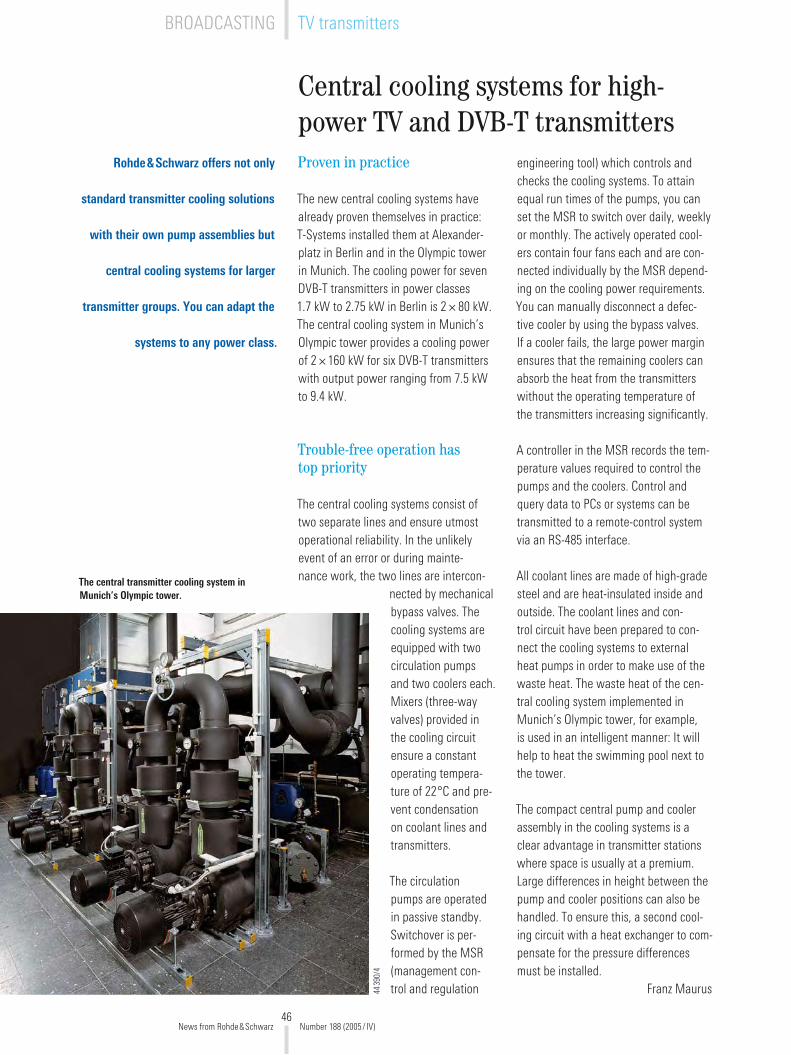
46
Central cooling systems for high-power TV and DVB-T transmitters
Rohde&Schwarz offers not only
standard transmitter cooling solutions
with their own pump assemblies but
central cooling systems for larger
transmitter groups. You can adapt the
systems to any power class.
engineering tool) which controls and checks the cooling systems. To attain equal run times of the pumps, you can set the MSR to switch over daily, weekly or monthly. The actively operated cool-ers contain four fans each and are con-nected individually by the MSR depend-ing on the cooling power requirements. You can manually disconnect a defec-tive cooler by using the bypass valves. If a cooler fails, the large power margin ensures that the remaining coolers can absorb the heat from the transmitters without the operating temperature of the transmitters increasing significantly.
A controller in the MSR records the tem-perature values required to control the pumps and the coolers. Control and query data to PCs or systems can be transmitted to a remote-control system via an RS-485 interface.
All coolant lines are made of high-grade steel and are heat-insulated inside and outside. The coolant lines and con-trol circuit have been prepared to con-nect the cooling systems to external heat pumps in order to make use of the waste heat. The waste heat of the cen-tral cooling system implemented in Munich’s Olympic tower, for example, is used in an intelligent manner: It will help to heat the swimming pool next to the tower.
The compact central pump and cooler assembly in the cooling systems is a clear advantage in transmitter stations where space is usually at a premium. Large differences in height between the pump and cooler positions can also be handled. To ensure this, a second cool-ing circuit with a heat exchanger to com-pensate for the pressure differences must be installed.
Franz Maurus
The central transmitter cooling system in Munich’s Olympic tower.
4439
0/4
Proven in practice
The new central cooling systems have already proven themselves in practice: T-Systems installed them at Alexander-platz in Berlin and in the Olympic tower in Munich. The cooling power for seven DVB-T transmitters in power classes 1.7 kW to �.75 kW in Berlin is � × 80 kW. The central cooling system in Munich’s Olympic tower provides a cooling power of � ×160 kW for six DVB-T transmitters with output power ranging from 7.5 kW to 9.4 kW.
Trouble-free operation has top priority
The central cooling systems consist of two separate lines and ensure utmost operational reliability. In the unlikely event of an error or during mainte-nance work, the two lines are intercon-
nected by mechanical bypass valves. The cooling systems are equipped with two circulation pumps and two coolers each. Mixers (three-way valves) provided in the cooling circuit ensure a constant operating tempera-ture of ��°C and pre-vent condensation on coolant lines and transmitters.
The circulation pumps are operated in passive standby. Switchover is per-formed by the MSR (management con-trol and regulation
News from Rohde&Schwarz Number 188 (�005/ IV)
BROADCASTING TV transmitters

47
Transportable Microwave Monitoring System R&S®TMS500
Transportable monitoring system for frequencies up to 110 GHzIncreasing demand for fre-quency in the microwave range
The increasing need for powerful com-puter networks is also boosting the demand for fast data links, which are increasingly being implemented via radio links. Since frequency bands are already densely occupied, users are often forced to switch to higher fre-quency ranges. However, numerous types of radio equipment and radar sys-tems already operate in this range. Reg-ulatory authorities thus have to monitor
the entire microwave range up to 40 GHz and above to identify unauthorized emis-sions and to set up a reliable database for future frequency assignments.
In the microwave range, you will often find directional radio links with antennas with strong directivity. In the event of interference, these antennas cannot be examined from just any fixed measure-ment stations. Instead, you have to set up the measurement system at the loca-tion of the receiving antenna with inter-ference.
FIG 1 The Transportable Microwave Monitoring System R&S®TMS500 is ready for on-site operation within a few minutes.
43386/1
Many transmitters operate above
3 GHz, the frequency limit of conven-
tional receivers. Some of them are
used for WLAN applications, but also
for broadcasting and TV satellites
as well as for microwave and radar
systems. It is necessary to monitor all
these transmitters, determine their
data in order to plan reliably, and find
possible interference in this range.
News from Rohde&Schwarz Number 188 (�005/ IV)
Monitoring systemsRADIOMONITORING
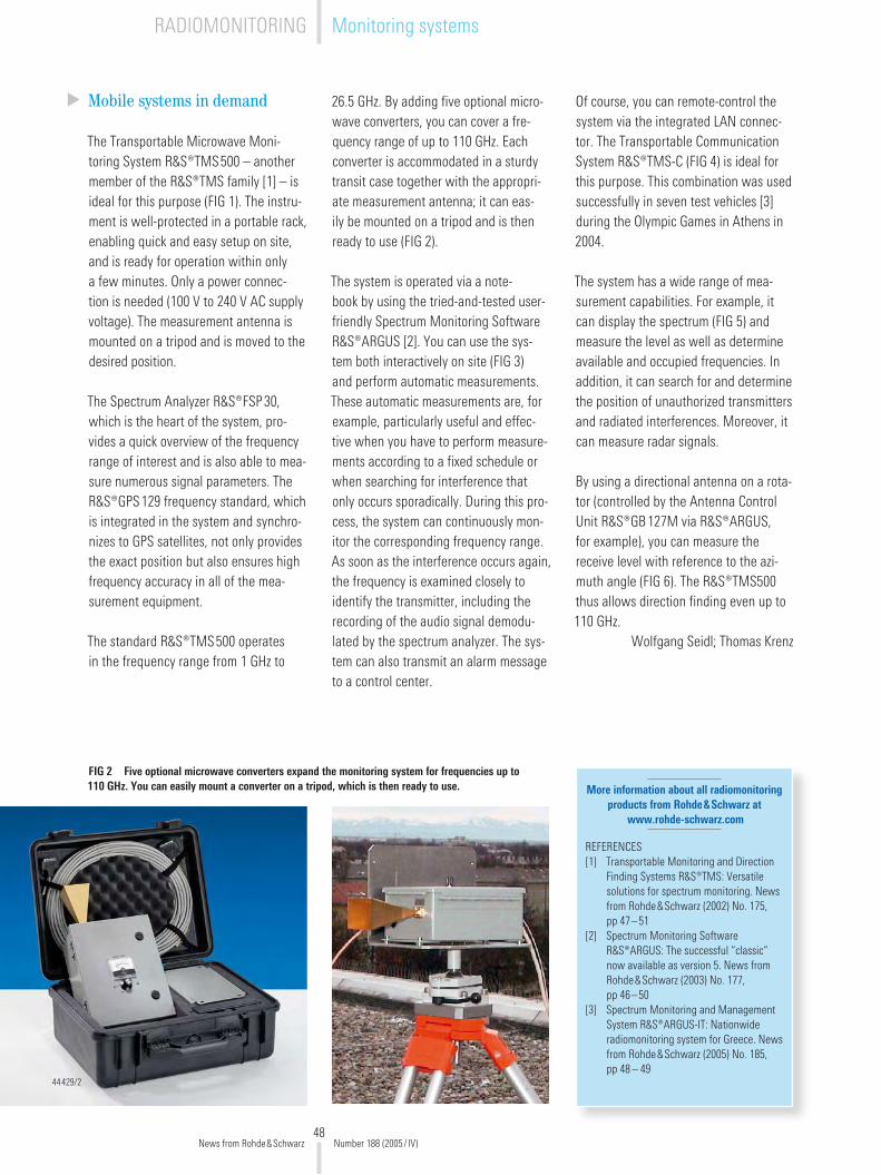
48
Mobile systems in demand
The Transportable Microwave Moni-toring System R&S®TMS500 – another member of the R&S®TMS family [1] – is ideal for this purpose (FIG 1). The instru-ment is well-protected in a portable rack, enabling quick and easy setup on site, and is ready for operation within only a few minutes. Only a power connec-tion is needed (100 V to �40 V AC supply voltage). The measurement antenna is mounted on a tripod and is moved to the desired position.
The Spectrum Analyzer R&S®FSP30, which is the heart of the system, pro-vides a quick overview of the frequency range of interest and is also able to mea-sure numerous signal parameters. The R&S®GPS1�9 frequency standard, which is integrated in the system and synchro-nizes to GPS satellites, not only provides the exact position but also ensures high frequency accuracy in all of the mea-surement equipment.
The standard R&S®TMS500 operates in the frequency range from 1 GHz to
�6.5 GHz. By adding five optional micro-wave converters, you can cover a fre-quency range of up to 110 GHz. Each converter is accommodated in a sturdy transit case together with the appropri-ate measurement antenna; it can eas-ily be mounted on a tripod and is then ready to use (FIG �).
The system is operated via a note-book by using the tried-and-tested user-friendly Spectrum Monitoring Software R&S®ARGUS [�]. You can use the sys-tem both interactively on site (FIG 3) and perform automatic measurements. These automatic measurements are, for example, particularly useful and effec-tive when you have to perform measure-ments according to a fixed schedule or when searching for interference that only occurs sporadically. During this pro-cess, the system can continuously mon-itor the corresponding frequency range. As soon as the interference occurs again, the frequency is examined closely to identify the transmitter, including the recording of the audio signal demodu-lated by the spectrum analyzer. The sys-tem can also transmit an alarm message to a control center.
More information about all radiomonitoring products from Rohde&Schwarz at
www.rohde-schwarz.com
REFERENCES[1] Transportable Monitoring and Direction
Finding Systems R&S®TMS: Versatile solutions for spectrum monitoring. News from Rohde&Schwarz (�00�) No. 175, pp 47–51
[�] Spectrum Monitoring Software R&S®ARGUS: The successful “classic“ now available as version 5. News from Rohde&Schwarz (�003) No. 177, pp 46–50
[3] Spectrum Monitoring and Management System R&S®ARGUS-IT: Nationwide radiomonitoring system for Greece. News from Rohde&Schwarz (�005) No. 185, pp 48 – 49
Of course, you can remote-control the system via the integrated LAN connec-tor. The Transportable Communication System R&S®TMS-C (FIG 4) is ideal for this purpose. This combination was used successfully in seven test vehicles [3] during the Olympic Games in Athens in �004.
The system has a wide range of mea-surement capabilities. For example, it can display the spectrum (FIG 5) and measure the level as well as determine available and occupied frequencies. In addition, it can search for and determine the position of unauthorized transmitters and radiated interferences. Moreover, it can measure radar signals.
By using a directional antenna on a rota-tor (controlled by the Antenna Control Unit R&S®GB1�7M via R&S®ARGUS, for example), you can measure the receive level with reference to the azi-muth angle (FIG 6). The R&S®TMS500 thus allows direction finding even up to 110 GHz.
Wolfgang Seidl; Thomas Krenz
FIG 2 Five optional microwave converters expand the monitoring system for frequencies up to 110 GHz. You can easily mount a converter on a tripod, which is then ready to use.
444�9/�
News from Rohde&Schwarz Number 188 (�005/ IV)
RADIOMONITORING Monitoring systems

49
FIG 4 The monitoring system can be
completely remote-controlled by using the Transportable Communi-
cation System R&S®TMS-C.44007/�
FIG 3 By using Spectrum Monitoring Software R&S®ARGUS, you can conveniently operate the sys-tem. This figure shows the set-tings for the Spectrum Analyzer R&S®FSP30.
FIG 6 By using a directional antenna on a rotator, you
can measure the receive level as a function of the azimuth angle.
FIG 5 Display of the measured spectrum.
News from Rohde&Schwarz Number 188 (�005/ IV)

50
Rohde&Schwarz Japan K.K. receives national award
Rohde&Schwarz Japan K.K. has received the Invest Japan Award from the Japanese Minister for Economics, Trade and Industry for its invest-ment policy. The Invest Japan Award is given to foreign com-panies that help to further stimulate the Japanese econ-omy by introducing new prod-ucts and advanced technol-ogies.
Rohde&Schwarz Japan K.K. was founded in Tokyo in �003 as a Japanese subsidiary of Rohde&Schwarz. In May �004, Rohde&Schwarz Japan K.K. established branch offices in Osaka and Shin-Yokohama for direct sales. In Novem-ber �004, a service center was set up in Saitama to pro-vide technical support for the products. Another reason why Rohde&Schwarz Japan received the award is the company’s rap-idly growing share of the market in Japan.
Certification in accor-dance with ISO 170�5 for Rohde&Schwarz USA
The Rohde&Schwarz calibra-tion laboratory in Columbia, Maryland, has received A2LA accreditation for the ISO /IEC 17025 laboratory standard. ISO 17025 is an international standard for assessing the technical competency of cali-bration laboratories. Its prac-tices help to ensure accurate data generation, controlled test methods, repeatable pro-cedures, properly trained per-sonnel and optimum manage-ment.
The certification marks an important milestone for Rohde&Schwarz. “This achieve-ment ensures that our custom-ers consistently receive tested and proven services that can only come from a laboratory carrying ISO 170�5 accredita-tion,“ said Barry Fleming, the company‘s US service manager. ISO 170�5 certification was accompanied by ANSI/NCL Z540 certification. For detailed infor-mation about A�LA accredita-tion, please visit www.a�la.org.
ACCESSNET®-T mobile radio system recertified
The ACCESSNET®-T TETRA mobile radio system from R&S BICK Mobilfunk has again been recertified for interoperability (IOP). Since the system is continuously enhanced, official certifica-tion tests were again carried out in Bad Münder at the end of last year.
ISCTI (Istituto Superiore delle Comunicazioni e delle Tecnol-ogie dell’Informazione), which is the certification body of the Italian Communications Ministry and is accredited by the TETRA MoU Association, supervised and performed these tests. The tests lasted several weeks, during which all renowned manufactur-ers of TETRA terminals visited R&S BICK Mobilfunk’s head-quarters in Bad Münder. The certificates and test results have been published on the TETRA MoU website and the Rohde&Schwarz Internet pages for general viewing. The multivendor principle within the TETRA standard is based on the IOP certification tests, which, in turn, substantiate this principle. R&S BICK Mobil-funk is an independent system supplier that is continuously developing system technology in accordance with the TETRA standard, as is evidenced by the company’s history of pass-ing the IOP certification tests on a regular basis.
Setup of TETRA radio system in Russia
At the end of September 2005, Rohde&Schwarz participated in an international conference in Moscow on setting up a uniform TETRA radio network. The conference was orga-nized by the magazine Net-work Computing&Telecomm-unications and the Russian Ministry of Communications and Information.
Max Zerbst, Vice President of R&S BICK Mobilfunk, lectured on Rohde&Schwarz TETRA solutions for mission-criti-cal communications in front of many representatives from gov-ernmental agencies as well as providers and manufacturers of radio technology. These solu-tions are based on the IP-based Mobile Radio Communications Architecture IpMCA® and can be adapted to new technologi-cal developments by means of appropriate updates (see article on page 4). They thus provide safety of investment and flexi-bility, which are also of immedi-ate importance to Russia. Since Russia has several radio com-munications systems which are not compatible with each other, the Russian Ministry of Communications and Informa-tion had already taken mea-sures in �003: A working group was commissioned by decree No. 161 to coordinate the TETRARUS project. The objec-tive of this project is to pro-vide the agencies with smooth and secure communications at all levels on the basis of TETRA technology. The solutions pre-sented by Rohde&Schwarz were impressive.
Akihiko Yoshimura, Representative Director, and Günter Loll, Managing Director of Rohde&Schwarz Japan K.K., with the award.
News from Rohde&Schwarz Number 188 (�005/ IV)
InternationalNEWSGRAMS
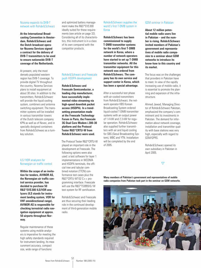
51
GSM seminar in Pakistan
About 12 million poten-tial mobile radio users live in Pakistan – and the num-ber is rising. Rohde&Schwarz invited members of Pakistan’s government and representa-tives of mobile radio compa-nies to a seminar about GSM networks to introduce its know-how to this country and its market.
The focus was on the challenges that providers in Pakistan have to meet. In view of the rapidly increasing use of mobile radio, it is essential to promote the plan-ning and expansion of the infra-structure.
Ahmed Jawad, Managing Direc-tor of Rohde&Schwarz Pakistan, emphasized the company‘s com-mitment and its investments in Pakistan. The demand for infor-mation about network coverage, installation and transmitter qual-ity with base stations was very high, especially with regard to GSM/GPRS.
Rohde&Schwarz opened its own subsidiary in Pakistan in April �005.
Rohde&Schwarz and Freescale push HSDPA development
Rohde&Schwarz and Freescale Semiconductor, a leading chip manufacturer, have successfully imple-mented video streaming via high-speed downlink packet access (HSDPA). In a trend-setting presentation made at the Freescale Technology Forum in Paris, the Freescale 3G Dual Core Modem i.300-30 platform and the Protocol Tester R&S®CRTU-W from Rohde&Schwarz were used.
The Protocol Tester R&S®CRTU-W played an important role in the development at Freescale. The following options were also used: a test software for layer 1 implementations in WCDMA and HSDPA terminals, the offi-cial tree and tabular com-bined notation (TTCN) con-formance test cases plus the R&S®CRTU-WT0� C++ pro-gramming interface. Freescale will use the R&S®TS8950G/W test system for RF certification.
Rohde&Schwarz and Freescale are thus securing their leading role in the continued develop-ment of third-generation mobile radio.
Rohde&Schwarz supplies the world’s first T-DMB system in Korea
Rohde&Schwarz has been commissioned to supply T-DMB transmitter systems for the world’s first T-DMB network in Korea, where a number of network operators have started to set up T-DMB transmitter networks. All the transmitter equipment for this network was ordered from Rohde&Schwarz. The com-pany has its own service and support center in Korea, which has been a special advantage.
After a successful test phase with air-cooled transmitters from Rohde&Schwarz, the net-work operator KBS Korean Broadcasting System ordered liquid-cooled T-DMB transmitter systems with an output power of 1.4 kW and �.3 kW for regu-lar operation. Rohde&Schwarz also supplied further transmit-ters with air and liquid cooling for SBS (Seoul Broadcasting Sys-tem), MBC and YTN. Installation will be completed by the end of �005.
ILS/VOR analyzers for Norwegian air traffic control
Within the scope of an invita-tion for tenders, AVINOR AS, the Norwegian air traffic con-trol service provider, has decided to purchase 50 R&S®EVS300 ILS/VOR ana-lyzers (ILS stands for instru-ment landing system, VOR for VHF omnidirectional range). AVINOR AS is responsible for checking terrestrial radio nav-igation equipment at approx. 50 airports throughout Nor-way.
Regular maintenance of these systems using mobile analyz-ers is imperative for meeting the high safety standards required for instrument landing. Its mea-surement accuracy, compact size, wide range of functions
Nozema expands its DVB-T network with Rohde&Schwarz
At the International Broad-casting Convention in Amster-dam, Rohde&Schwarz and the Dutch broadcast opera-tor Nozema Services signed a contract for the delivery of DVB-T transmitters to be used to ensure nationwide DVB-T coverage of the Netherlands.
At present, only the most densely populated western region has DVB-T coverage. To provide digital TV throughout the country, Nozema Services plans to install equipment at about 30 sites. In addition to the transmitters, Rohde&Schwarz will provide the liquid cooling system, combiners and antenna switching equipment. The trans-mitter systems will be installed in various transmitter towers of the Dutch telecom company KPN as well as of Novec, and in specially designed containers from Rohde&Schwarz as a turn-key solution.
and optimized battery manage-ment make the R&S®EVS300 ideally suited for these require-ments (see article on page 3�). Considering all of its characteris-tics, this instrument is in a class of its own compared with the competitor products.
Many members of Pakistan‘s government and representatives of mobile radio companies from Pakistan took part in the seminar on GSM networks.
News from Rohde&Schwarz Number 188 (�005/ IV)

New
s fro
m R
ohde
&Sc
hwar
z 188
(�00
5/IV
) · P
D 07
58.0
145.
7�
www.rohde-schwarz.com
Europe: [email protected] · North America: [email protected] · Asia: [email protected]
Recommended