GEGrid Solutions
Applications• Advanced Substation Gateway with customizable
HMI for multiple floating windows and dual monitors
• Advanced IEC 61131-3 compliant automation engine
• IEC 61850 Edition 2 compatible (Client)
• Simultaneous and comprehensive protocol support
• Comprehensive logging facilities for substation data including events, user actions, cyber security, connectivity
• Automatic or manual acquisition of any type of files from Intelligent Electronic Devices (IEDs)
• Single setup and configuration tool across the platform
• Support for redundant substation systems
Security • Support for Trusted Platform Module (TPM) and
Storage Encryption
• Various user access levels: Administrator, Supervisor, Operator, Observer, Pass through
• Secure tunneling from master station via TLS for DNP3/TCP, Modbus/TCP and IEC 104
• Secure file transfer to enterprise server using RSYNC/SSH, SFTP, FTP
• Secure Interactive Access using HTTPS and SSH
• Secure boot, secure firmware upgrade, storage encryption, local maintenance confirmation, and chassis intrusion detection
• Built-in firewall
Hardware• High performance multi-core CPU (Dual: 128 GB or
Quad: 256 GB SED)
• Hot Swappable Dual Power Supply
• 6x native SFP Ethernet ports [PRP]
• Support for Redundant LAN Pairs
• Supports up to 3x M.2 SATA SED storage (G500 v1.0 supports 1x M.2 SATA SED)
• Compliant to IEC 61850-3 and IEEE 1613
• Standard time synchronization [PTP IN/OUT, IRIG-B IN]
Advanced Substation GatewayGE’s Multilin G500 is a member of the advanced Multi-function Controller Platform (MCP). This platform offers a high-capacity, secure, future-proof, and substation-hardened set of modular and scalable hardware and software components designed to simplify deployment, operation and maintenance of automation systems for a variety of applications including:
• Centralized automation for transmission & distribution substations
• Industrial substation automation systems
• Asset performance management
• Distribution automation & microgrid
• Secure substation automation systems
• Retrofit of substation automation systems
The MCP makes it possible for a single device to host multiple functions and applications such as Supervisory Control and Data Acquisition (SCADA) Concentrator, Remote terminal Unit (RTU), Human Machine Interface, Advanced Cyber Security Features, and Non-Operational Data Storage. Consolidation of functions reduces the cost of deployment and operation while increasing system reliability through a reduced number of devices in the system.
The G500 is designed to provide a reliable and accurate collection of data (metering, status, events and faults) from serial or LAN-based intelligent substation devices to master applications such as SCADA, EMS, DMS, DCS or other enterprise applications. With its modern and robust cyber security features, the G500 is designed for smooth integration into NERC CIP and cyber security environments while consolidating functions such as Ethernet communications, time synchronization, HMI and SCADA applications.
Key Benefits• Standardize substation architectures with a cost-effective, IEC 61850-3 compliant platform, scalable for
small to large systems with up to 200,000 data points
• Simplify engineering and operations through consolidation of functions
• Reduce system cost by eliminating dedicated HMI computers, external Ethernet switches and leveraging the built-in configurable PRP
• Optimize Cyber Security management with hardened Linux based operating system and container technologies enabling modular updates instead of single image updates
• Improve Cyber Security protection with state of the art Trusted Platform Module (TPM) technologies for data encryption
• Improve time synchronization performance with Precision Time Protocol (PTP/IEEE1588)
• Expand serial connectivity to up to 20 physical ports with the three PCIe expansion modules and up to 120 virtual ports
• Cost-effective retrofit solutions where individual automation and communication components can be replaced by only one device
• Ease of use and configuration and standardization with graphical configurations, drop down menus, pre-configured device maps, and single platform DS Agile Studio software
Multilin G500

GEGridSolutions.com2
G500 Advanced Substation Gateway
OverviewGE’s G500 is a secure, hardened, advanced substation gateway that collects metering, status, event , and fault report data from serial or LAN based intelligent substation devices. The G500 summarizes data from the substation devices and makes it available locally /remotely through a standard secure web browser (HTTPS). It supports serial and/or LAN connections to SCADA masters.
Advanced Gateway
The G500 collects data from substation protection, control, monitoring, RTU, and other intelligent devices, pre-processes the data and moves it up to EMS and DMS SCADA systems providing centralized substation management. Gateway features include:
• Data collection, concentration and visualization
• IEC 61850 Gateway
• Device Redundancy
• Built-in Media Support
• File retrieval capabilities
• Built-in HMI
Advanced Automation
The G500 provides the computing platform necessary to automation intricate substation procedures and processes safely and efficienty. The advanced and customized automation programs are created using IEC 61131 compliant tools and math functions are performed on data points using the built-in calculator tools.Automation features include:
• HMI, One Line Viewer and Annunciator
• Mathematical Control Logic
• Programmable Logic using LogicLinx
• Accumulator Freeze
• Analog Value Selection
• Control Lockout
• Double Point Association and Input Point Suppression
• Redundant I/O
• Alarm Management
• Hardware Asset Management Application
• System Status Manager
• Load Shedding and Curtailment
Fault Recording/Data Logging
Using pass-through connections, users can extract valuable non-operational data such as digital fault records (DFR), event and oscillography files. The user can also access the historical log files and upload the archived data for trending and analysis. Fault recording features include:
• Data Logger and Analog Reports
• Trend Viewer
• Database Exporter
• Automatic Record Retrieval Manager and Runtime viewer
Secure Remote Access
The G500 allows maintenance and relay engineers to securely access substation devices, locally or remotely, through advanced visualization and communication tools, increasing operational efficiency. Secure remote access features include:
• Access to Operational and Non-operational Data
• Pass-through/Terminal Server
• Role Based Access Control
• Virtual Serial Ports
• Build-in Firewall
• Local Authentication, Authorization and Auditing(Syslog)
• Electronic Access Point (EAP) - OpenVPN
G500 Multifunction Controller Platform Applications
System operation Enterprise applications
Substation control room applications
SCADA data Non-operational data
Data and IED Integration
Substation data gateway
Substation security gateway
Online condition monitoring
Substation data concentrator
Asset managementProtection and controlMaintenance and engineering
Central security server
Substation HMI
G500 Advanced Substation Gateway
SUBSTATION
Substation IEDs Asset M&D Digital Fault Recorders Power Quality Meters Legacy Devices
SCADA/EMS/DMS

GEGridSolutions.com 3
G500 Advanced Substation Gateway
Engineering Access
Advanced Gateway
Data Collection, Concentration and Visualization
The G500 advanced substation gateway, when operating as a SCADA host, collects, filters, and sorts data from a wide range of intelligent devices (RTUs, relays, meters) in the substation and preserves original data time stamp for accurate sequence of event. Data can be presented to multiple SCADA hosts. The G500 comes with a built-in suite of protocols and security applications to facilitate communication with various substation devices and SCADA hosts, including:
• DNP3 serial and TCP/IP (client & server)
• IEC 61850 (client)
• Modbus™ serial & TCP/IP (client & server)
• IEC60870-5-101/103/104 (client)
• IEC60870-5-101/104 (server)
• SEL Fast Meter/SEL ASCII
• Generic ASCII protocols
IEC 61850
The IEC 61850 Client application allows the G500 to act as a powerful IEC 61850 data concentrator. The G500 also includes valuable features such as Dynamic Data Sets, Buffered Control Blocks, and Enhanced Security Controls.
Device Redundancy
Besides being able to operate as a standalone unit, the G500 can be configured to operate in a redundant mode.
To improve the reliability of data collected from devices and transmitted to the master stations, Dual G500s can be deployed to create an active and standby (back-up) system.
While only one G500 is active at a time, both the active and standby G500 units are constantly in sync. Through the monitoring of the system health between the two units, the standby unit automatically takes over when the active unit goes down.
The G500 supports a warm redundancy, where there is a slight intermittence from when the standby G500 switches to becoming active.
The G500 also supports a hot redundancy, where there is zero packet loss as the standby G500 automatically becomes active.
Scalable from Small to Very Large Applications
G500
Enterprise Applications
Substation HMI SCADA Masters
PRP-APRP-2A
PRP-BPRP-2B
D20E Ethernet IO
Serial CommunicationsI/Os
I/Os
Typical Applications
• Advanced substation automation application (interlocking, alarm grouping/reduction, data conversion)
• Online Asset Management and condition monitoring
• Enhanced gateway used as an Electronic Access Point (EAP)
• Local authorization account management. Role-based-access-control supported.
• Extremely large size database, high speed remote IO, IEDs (serial and redundant LAN PRP)
• High performance substation level HMI integrated to the gateway
• Distribution automation applications
• Automated file collection from IEDs and provision to enterprise stations through a push mechanism
• Complex custom logic automation and event coordination using high de-centralization to IEDs (possible due to high speed redundant LAN).
• Very good performance and availability (Gateways can be redundant)

GEGridSolutions.com4
G500 Advanced Substation Gateway
Predix Edge Connectivity
PredixTM Edge is an IIoT computing platform positioned at the intersection of control systems and the enterprise. With powerful connectivity and management capabilities, support for container-based apps and analytics and scalable deployment options, Predix Edge simplifies data collection and supports edge computing needs from the device to the data center.
The G500 allows built-in support for the Predix Edge Manager Connectivity for the fleet level and local device management. The features include:
• Secure and Hardened Linux Based Predix Edge OS
• Predix Edge Technician Console Support for Local Device Management
• Predix Edge Manager Connectivity through WAN to support Fleet Level Device Management
Redundancy
The following G500 applications are supported under the Hot standby mode of operation:
• Calculator
• Modulus Client
• DNP 3.0 Server
• DNP 3.0 Client
• D20 Network Client
• Digital Event Manager
• IEC 61850 Client
• G500 Event Logger
• Logiclinx IEC 61131-3 SoftLogic
• G500 Redundancy Manager
• G500 System Status Manager
• G500 Terminal Services
• Firewall
• Secure Enterprise Connectivity
Built-in Media Support
The G500 supports various communication media types. The 8x RS-232, RS-485 serial interfaces are accessible via individual RJ45 connectors on the rear of the unit.
Additional serial interfaces can be added using PCIe expansion cards. Baud rates of 300, 600, 1200, 2400, 4800, 9600, ... 115.2k are supported. The RS232 mode supports flow control and handshaking signals in addition to a software controlled mode of operation between RS232 or RS485. All software selection persists when power to the unit is cycled. The serial interfaces support IRIG-B and a +12V output is available on 2x serial interfaces.
6x Ethernet ports are assessible through SFP cages: The following SFP transceivers are supported:
• 100/1000BASE-T (RJ45 copper medium)
• 100BASE-FX (LC fiber multimode)
• 1000BASE-SX (LC fiber multimod
IEC 62439-3 (Edition 2), Parallel Redundancy (PRP) Protocol
Substation LAN redundancy has been traditionally accomplished by reconfiguring the active network topology in case of failure. Regardless of the type of LAN architecture (tree, mesh, etc.), reconfiguring the active LAN requires time to switchover, during which the LAN is unavailable.
Parallel Redundancy Protocol is an IEC 62439-3 data communication network standard which is often used to overcome single network failure without affecting the data transmission. PRP is independent of the communication protocols and provides no packet loss (“zero recovery time”) availability by using connected nodes which transmit and receive over two independent network active paths. Under PRP, each network node has two Ethernet ports attached to two different local area networks, using standard bridges, and similar topology.
The G500 can communicate simultaneously to devices connected to a common network, carrying mixed traffic: single LAN, legacy redundant or dual LAN, and PRP. This aids in implementing PRP in brown field installations, taking advantage of possible spare ports on existing managed switches LAN infrastructure.

GEGridSolutions.com 5
G500 Advanced Substation Gateway
Analog Report Generation
In addition to the data logging capability within the G500, users can create or import report templates and configure online and offline reports from operation and non-operation analog data. While online reports can be retrieved instantly and are an extension of the data logger periodic reports, offline reports can be retrieved daily, weekly or monthly.
Offline Reports:
• Users can use the Analog report application to generate offline reports
• Users can configure different types of analog reports. For example: Shift , daily, weekly and monthly
• Users can use the offline report viewer to view generated reports
• Output format types includes: PDF, Excel® and HTML
Online Reports:
• This is an extension of the data logger periodic reports
• Users can use the online report viewer to view periodic data logger reports
• Output format types includes: PDF, Excel® and HTML
Types of Offline Reports and Key Parameters:
REPORT TYPE REPORT DURATION START TIME ALIGNMENT LOGGING INTERVAL LOGGING ALIGNMENT
Shift Configurable: 4, 6, 8 or 12 hours Configurable: 0-23 hour Configurable: 15, 30, 60 minutes Configurable: 00:00, 00:15, 00:30 or 00:45
Daily Fixed: 1 day Configurable: 0-23 hour Configurable: 15, 30, 60 min and 4, 6, 8 hours
Configurable: 00:00, 00:15, 00:30 or 00:45
Weekly Fixed: 7 days Configurable: 0-23 hour Configurable: 12 and 24 hours Configurable: 0-23 hours
Monthly Fixed: 7 days Configurable: 1-31 date Configurable: 12 and 24 hours Configurable: 0-23 hours
Key Features:
• Can configure up to 8 VPN Clients; Can at a maximum serve up to 3 VPN Clients.
• Certificate-key format support for openvpn client [Windows]
• Network interface combination available for Routing
• Support for 1024 Rules in Whitelist
• Rules includes support for:
- Any ICMP
- Useful ICMP
- TCP & UDP
• Supports Redundancy (Warm/Hot)
OpenVPN Architecture Example
WAN
EV PC - Enterprise
Server
Modbus TCP/SSH Over VPN Tunnel
Substation LAN
VPN Client
Modbus TCP/SSH
Substation
VPN Server
GE Relay GE Relay GE Relay
G500
LogicLinx Editor and Mathematical Control Logic

GEGridSolutions.com6
G500 Advanced Substation Gateway
Advanced AutomationThe G500 acts as a centralized, substation-hardened computing platform within an advanced automation system. With its advanced IEC 61131 compliant programmable logic tool, users can create simple to complex custom programs for a variety of automation applications such as but not limited to:
• Sequence Switching
• Interlocking
• Auto-sectionalizing
• Auto-reclosing
• Load Tap Changer Control
• Cap. Bank Control
• Reactor Switching
• Alarm Grouping
Mathematical Control Logic
Using the calculator tool, users can create advanced solutions that group, manage and control points to produce the required automation results.
The calculator tool can perform mathematical, logical, or timer based operations on data points stored in the G500. Using a graphical interface, users can define logical expressions using mathematical functions such as addition, multiplication, logarithm, greater than, less than, as well as other boolean functions.
IEC 61131-3 Compliant Programmable Logic
For more advanced applications, programmable logic (LogicLinx) software provides PLC functionality on the G500 platform. LogicLinx offers textual and graphical languages defined in the IEC 61131-3 standard for PLC programming environments, including Sequential Functions Chart, Instruction List, Structured Text, Ladder Diagram and Function Block Diagram. In addition, a wide range of arithmetic, boolean and logical operations are supported.
HMI, One Line & Annunciator
The G500 supports an embedded HMI/ Annunciator functionality, that is accessible through a secure application. Alternatively, the HMI could be accessed with the use of up to 2x4k keyboard and mouse directly connected to the G500’s display ports. Users have access to all data points in the systems, alarm screens, communications status screens and dynamic one-line diagrams, all through a secure protocol.
Multiple floating windows for different screen views are supported. Being able to access multiple floating windows or screens improves the productivity of operators. Users are able to customize the different views to match different
background colors or skins to sooth different mood. For every screen type, the layouts created are persistent to the last layout size or position. This is very useful in that users do not have to to keep recreating the same layout.
The HMI supports the following security features to ensure secure remote or local access:
• Configurable auto logout/login for Remote and Local HMI access
• Disabling of Remote HMI Non-Observer Privileges
• Login to specific custom screens for added security to sensitive displays
• Remote access to Redundant or Active HMI screens
• Support for commissioning forcing control/feedback and acknowledge individual/group alarms from one-line diagram
Alarm ManagementThe G500 Alarm groups are user-definable, with up to 256 groups allowed. Each group has its own descriptive and display parameters. Alarms may belong to more than 1 group, or none at all. “Critical” and “Default” groups are built-in. SCADA points for the alarm groups remain on-line if component alarm points go offline. SCADA points are provided to acknowledge a group of alarms. Individual alarms must be acknowledged via the G500 GUI.
Advanced Database Points Management
The flexibility of the G500 configuration system enables users to create and manage database
points for control or reporting by leveraging the following:
Double Point - Two digital input points can be associated to form double points, which are also known as 4-state points. This is very useful in situations where a user would like to represent and report the different states of a device. Instead of the typical binary “on”, or “off” states, other states could be, “intermediate-state” or “bad-state” or whatever the specified states represents. This provides additional visibility of the condition of the asset.
Accumulator Freeze - It might be useful to define groups of points and associate peculiar action(s) to the group based on certain conditions. The accumulator freeze function is used to define a group of points whose values are to be frozen periodically or upon demand. This additional level of automation increases the visibility required when monitoring certain important processes for specific conditions.
Analog Value Selection - The Analog value selection functionality enables the user to define a group of analog input points that have priority. This is valuable especially in a system with numerous points and events. It may be important to identify what’s most critical to report. For example: Within the prioritized group, a valid and highest priority point can be reported to a single analog input point.
Input Point Suppression - This is useful during maintenance operations to prevent spurious OFFLINE alarms and false readings while devices are powered off or disconnected. Users can

GEGridSolutions.com 7
G500 Advanced Substation Gateway
TFTP or IEC 61850 MMS
Secure machine to machine:
MODBUS-TCP/SSH with key management between G500 and Multilin UR Relays (version 7.x)
ARRM supports UR-SFTP integrated with key management between G500 and Multilin UR Relays (version 7.x)
Push records from the G500 using any RSYNC/SSH,FTP,SFTP client as needed or on a scheduled basis
File naming based on configurable parameters or the IEEE File Naming Convention for Time Sequence Data
Using SFTP, FTP, TFTP, IEC 61850 MMS, SEL Bin/GEN ASCII for automatic retrieval of: fault records, SOE and comtrade files, events, oscillography, settings, logs
disable groups of analog and digital input points by ignoring their real-time data or quality changes within selected applications. While points are suppressed, a predefined suppression value and the point suppressed quality flags are provided instead.
Control Lockout
The control lockout feature ensures that only a single master station can access a group of controls at one time. Can lock out groups of controls to allow for safer local maintenance. Users can create up to 8 remote control groups and up to 256 local control groups. Any digital output can be included in one remote and one local group. This provides a coordinated control of outputs and ensures that the right control actions are executed by the appropriate devices.
Redundant I/O
To improve the reliability and availability of data for critical processes, it is useful to specify a secondary data point for any point. Just as it is important to have a back-up (redundant) device, it is also useful to have a back-up (redundant) point that represents a real primary point. The value and quality of the redundant point is reported when the associated primary point is invalid or questionable.
Fault Recording / Data LoggingThe G500 can automatically retrieve event and oscillography files from devices such as Multilin UR Protective Relays, GE’s D25 Controllers, and IEC 61850 server devices. Using IEEE file naming standards, these event files are renamed and can be stored locally or securely sent to corporate servers using RSYNC, FTP or SFTP.
Data Logger
The Analog Data Logger provides a variety of means to monitor and record analog input point value changes into data files that can be retrieved by the user. A variety of recording methodologies are supported including, Continuous (all changes), Periodic, Time Weighted, Out of Range and Triggered by a digital input point.
Trend Viewer
All data recorded by the Analog/Digital Data Logger can be viewed by the Digital event recorder using the built in web-based Trend Viewer. Users can select the range of data to be used by time and date, alternately a real time streaming view can be displayed. Up to 8 data points (pens) can be displayed on a single view and support for curve fitting is available.
Database Exporter
The Database Exporter tool allows users to save Analog Data Logger and Digital event recorder points from the G500 to your local PC, using the WEB interface, in comma-separated values (CSV) format.
Automatic Record Retrieval
The Automated Record Retrieval Manager (ARRM) retrieves and stores record files from devices connected to the G500.
ARRM uses the Distributed Network Protocol (DNP) and the IEC 61850 protocol to communicate with a variety of devices, and uses the Trivial File Transfer Protocol (TFTP) SFTP, FTP, SEL Bin/GEN ASCII or IEC 61850 MMS to transmit the files from the IED to the device over a Local Area Network (LAN) or serial connection.
File RetrievalThe G500 file retrieval capability allows system event information to be collected and viewed using a web-based trend viewer.

GEGridSolutions.com8
G500 Advanced Substation Gateway
You can also retrieve downloaded records from the G500 using any FTP/SCP/SFTP client as needed or on a scheduled basis.
ARRM supports a configurable interval for polling connected devices. This can be activated or deactivated through the runtime viewer display screen.
ARRM supports file archival of EVE and CEV files from the SEL IEDs via serial or TCP connections.Secure Remote Access
G500 provides robust security environment, providing seamless integration with existing IT department policies. Role based Access Control, Secure Web Interface, Secure File Transfer, and extensive user activity logging provide a complete security toolkit required to achieve NERC-CIP compliance.
Non-operational DataUsing pass-through connections, the utility user can extract valuable non-operational data such as digital fault recording (DFR) records and event files. The user can also access the historical log files and upload the archived data for trending and analysis.
Pass-through/Terminal ServerA built-in terminal server emulator allows pass-through connections to be initiated to substation device (relay, meter, RTU or other device). Once the connection is established, the local event records can be uploaded from the substation devices and viewed remotely. Remote access can be secured with TLS or SSH.
Virtual Serial PortsVirtual serial ports eliminate copper wire
communications to feeder bays when a serial-only device is located in the bay. A small terminal server can be placed in the bay and connected to the Ethernet network, allowing all G500 serial client applications to connect directly to the serial device.
Role Based Access Control
Role Based Access Control is achieved using the
G500’s internal database; ensuring only authenticated and authorized users gain access the system.
Built-in FirewallThe G500 is equipped with a built-in firewall for enhanced gateway cyber security. G500’s firewall is designed to drop unsolicited or invalid routed packets. The firewall is preconfigured to
Secure Remote Access
Engineering Systems Secure Communications G500 Device Connections
G500 Advanced Substation Gateway provides substation hardened processing platform for secure data & device access:
• SCADA data concentrator• Device configuration tools• Remote device access• Engineering tools
Meeting industry standards ensures compatibility with communications and IT equipment . Supported Network Protocols include:
• HTTPS• SSH• SCP
• SFTP• CHAP• TLS
Bay Controllers
Protection Relays
Intelligent Devices
Use device software to obtain non-operational data such as trending and event records through the G500’s secure remote access functionality.

GEGridSolutions.com 9
G500 Advanced Substation Gateway
inspect outbound traffic on external interfaces and inbound traffic on both internal and external interfaces. The G500 automatically generates rules allowing inbound traffic on internal interfaces for all configured services, and inbound/outbound traffic for configured secure services on external interfaces. The rules are user configurable for inbound/outbound traffic customization.
Configuration SoftwareThe DS Agile Studio (DSAS) is an industry leading software toolset that simplifies every aspect of using Substation Automation products. DS Agile Studio integrates support for the complete portfolio of GE’s Substation Controllers with optimized performance and support for SGConfig workflow for simplified migration of the existing installations.
Online-based configuration: The G500 can be configured remotely through the use of a simple user pre-defined drop down lists of device point maps.
Offline-based configuration: Alternatively, the G500 can be configured using an excel-based bulk editor. This offline configuration
capability improves the flexibility and increases productivity for users configuring large number of database points.
IEC 61850 Substation Device LoaderA key benefit to using IEC 61850 based communications is the reduction in deployment costs for modern substation automation systems. The G500 IEC 61850 loader application guides users through a structured 4-step workflow to configure the IEC 61850 client application, reducing system configuration time.
Available device data, based on logical nodes, can be retrieved from the IEC 61850 Substation Configuration file (SCL files such as ICD, CID, SCD) or directly from the intelligent substation device using the IEC 61850 self-description.
The IEC 61850 device loader allows users to pick the specific logical nodes or data sets to be used for automation tasks or to be placed in the G500 database for upstream communications, reducing overall network traffic and system loading for increased system efficiency.
Using the IEC 61850 Dynamic Data Sets allows the configuration software to define the exact data to be retrieved from a substation device when initializing communications with that specific device. This allows users to configure the data sets through a single application rather than manually configuring data sets in each separate device, reducing mapping errors.
Device ConfigurationConfiguring the G500 to communicate with substation devices is simple and straightforward. Thanks to pre-configured map files, adding devices to the system only takes a few mouse clicks. Point maps can be customized to meet your specific needs, then applied for all devices requiring the modifications.Creating One-Line diagrams is quick and easy using the built-in, drag and drop One-Line designer application. Configuring alarm and alarm groups is simplified using a tree view point selection tool.
Online-based configuration: Connecting and configuring substation devices is simple by using pre-defined drop down lists of device point maps.
Simplified IEC 61850 configuration
Simplified device configuration
1. Create a Device Map file, once
2. Create multiple Connections to devices, re-using same Device Map file
1. Select SCL file2. Select Servers (IEDs)
4. Select Data Objects
3. Select Data Sets or create Dynamic DS
Done!Configuration Summary
GEGridSolutions.com10
G500 Advanced Substation Gateway
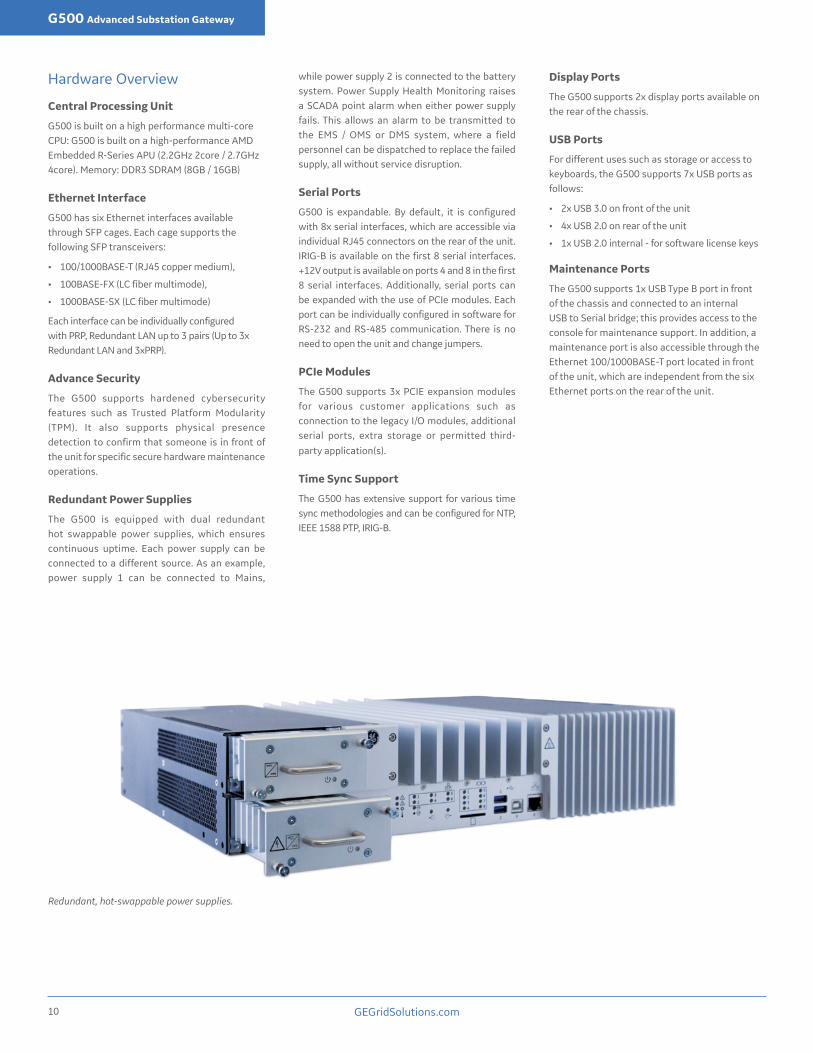
Redundant, hot-swappable power supplies.
Hardware Overview
Central Processing Unit
G500 is built on a high performance multi-core CPU: G500 is built on a high-performance AMD Embedded R-Series APU (2.2GHz 2core / 2.7GHz 4core). Memory: DDR3 SDRAM (8GB / 16GB)
Ethernet Interface
G500 has six Ethernet interfaces available through SFP cages. Each cage supports the following SFP transceivers:
• 100/1000BASE-T (RJ45 copper medium),
• 100BASE-FX (LC fiber multimode),
• 1000BASE-SX (LC fiber multimode)
Each interface can be individually configured with PRP, Redundant LAN up to 3 pairs (Up to 3x Redundant LAN and 3xPRP).
Advance Security
The G500 supports hardened cybersecurity features such as Trusted Platform Modularity (TPM). It also supports physical presence detection to confirm that someone is in front of the unit for specific secure hardware maintenance operations.
Redundant Power Supplies
The G500 is equipped with dual redundant hot swappable power supplies, which ensures continuous uptime. Each power supply can be connected to a different source. As an example, power supply 1 can be connected to Mains,
while power supply 2 is connected to the battery system. Power Supply Health Monitoring raises a SCADA point alarm when either power supply fails. This allows an alarm to be transmitted to the EMS / OMS or DMS system, where a field personnel can be dispatched to replace the failed supply, all without service disruption.
Serial Ports
G500 is expandable. By default, it is configured with 8x serial interfaces, which are accessible via individual RJ45 connectors on the rear of the unit. IRIG-B is available on the first 8 serial interfaces. +12V output is available on ports 4 and 8 in the first 8 serial interfaces. Additionally, serial ports can be expanded with the use of PCIe modules. Each port can be individually configured in software for RS-232 and RS-485 communication. There is no need to open the unit and change jumpers.
PCIe Modules
The G500 supports 3x PCIE expansion modules for various customer applications such as connection to the legacy I/O modules, additional serial ports, extra storage or permitted third-party application(s).
Time Sync Support
The G500 has extensive support for various time sync methodologies and can be configured for NTP, IEEE 1588 PTP, IRIG-B.
Display Ports
The G500 supports 2x display ports available on the rear of the chassis.
USB Ports
For different uses such as storage or access to keyboards, the G500 supports 7x USB ports as follows:
• 2x USB 3.0 on front of the unit
• 4x USB 2.0 on rear of the unit
• 1x USB 2.0 internal - for software license keys
Maintenance Ports
The G500 supports 1x USB Type B port in front of the chassis and connected to an internal USB to Serial bridge; this provides access to the console for maintenance support. In addition, a maintenance port is also accessible through the Ethernet 100/1000BASE-T port located in front of the unit, which are independent from the six Ethernet ports on the rear of the unit.

GEGridSolutions.com 11
G500 Advanced Substation Gateway
Front Panel
Modular, Hot Swappable Redundant Power Supplies • 20–54 VDC @10.2A • 110-270VDC @ 1.8A • 100-240VAC @2.1A
OLED Display for hardware asset management 100/1000 BASE-T
Maintenance Ethernet Port
USB Type B Console Port
USB 3.0 Ports
SD Card for Additional Storage
LED indication for IRIG-B Input
LED Indication for CPU Status
Enter/Return and Back/Escape Navigation
Buttons for OLED
LED Indication for Temperature of Unit
LED indication for Ethernet Ports
LED Indication for the 8x Serial Ports
Right and Left Navigation Buttons for OLED
Physical Presence Button
Power Supply LED Indication
+77dB internal buzzer
Back Panel
3x PCIe Module Interface
Solid State Relay of Form NO-C-NC for Output Alarm
Heat SinkLiquid resistant top Liquid resistant top
Power Supply Labels and Inputs
8x RJ45 Serial Ports
Reset ButtonDual Mode, Display Port Supports multi-stream transport (MST). Each port supports 1 monitor
6x SFP Cages for copper and fibre Ethernet connectors • 100/1000BASE-T (RJ45 copper medium) • 100BASE-FX (LC fiber multimode) • 1000BASE-SX (LC fiber multimode)
Audio Output 3.5 mm audio jack
for substation alarms
IRIG-B Input 4x USB 2.0 Ports
Status 1 - Ready LED indicating system is funcational
Status 2 / Operation Mode LED showing device mode (i.e.: Standby, Active)

GEGridSolutions.com12
G500 Advanced Substation Gateway
Technical SpecificationsProcessor, Memory, and StorageCPU AMD Embedded R-Series CPU
(2.2GHz 2core / 2.7GHz 4core)Memory DDR3 SDRAM (8GB / 16GB)Storage Self-encrypted Solid-State Drive (128 GB / 256 GB)
Operating SystemPredix Edge OS (Linux Kernel 4.14)
CommunicationsEthernet 6 Ethernet ports, configurable as independent LAN,
Redundant LAN and/or PRP Accessible via SFP modules:• 100/1000BASE-T (RJ45 copper)• 1000BASE-FX (LC fiber multimode)• 1000BASE-SX (LC fiber multimode)
Serial (RS-232/485) • 8x serial interfaces accessible via individual RJ45 connectors on rear of the unit
• Additional serial interfaces can be adding using PCIe expansion cards
• Serial interfaces use 16550 compatible UART• Support baud rates 300, 600, 1200, 2400, 4800,
9600, ... 115.2k• RS232 mode supports flow control and handshaking
signals (RTS,CTS,DCD)• Software controlled mode of operation between
RS232 or RS485 2/4 wires• Software controlled termination resistor (120 ohm)
for RS485 mode• All software selection persist when power cycled• IRIG-B available on all native serial interfaces• +12V output @ 6W max available on serial
interfaces 4 and 8
Time Synchronization (HW support) PTP Can be configured for IEEE1588 PTP IN and OUTIRIG-B input • Available as 3 positions removable Phoenix terminal
block on rear of the unit• Supports IRIG-B TTL
Video outputDisplay Port 2x DP++ (Dual-mode DisplayPort) available on the rear
of the chassisEach DP++ supports up to two multi-stream displays (Windows support only)Resolution:• up to UHD (4k, 3840x2160) for single displays
connected to each port
Audio output3.5 mm audio jack for substation alarmsBuilt in high (+77dB) pitch audio buzzer
USB ports• 2x USB 3.0 on front of the unit• 4x USB 2.0 on rear of the unit• 1x USB 2.0 internal - for software license keys
SD card (Windows support only)• SD, SDHC and SDXC SD-Cards according to Version
1.0, Version 2.0 and Version 3.0• Maximum SDXC size 64GB• SD card slot accessible on front of the unit, uses
push-pull mechanism
Maintenance portsConsole port • 1x USB Type B port on front of chassis
• connected to internal USB to Serial bridge, allows access to Console for debug
Local Ethernet 100/1000BASE-T maintenance Ethernet port accessible via front of the unit
Power SupplyDual/ Redundant hot-swappable power supplieseach with individual removable Phoenix terminal block
Low Voltage 20–54 VDC @10.2AHigh Voltage • 110-270VDC @ 1.8A
• 100-240VAC @ 2.1A
PhysicalDimensions 19 Inch rack mount (482.59 mm)
2U (3.47” / 88.12 mm) in height / 3U with Rack mounting kit installed12.20“(310.00 mm) in depthRack mount kit included: 6 mounting holes, 2 slotted for easy installation
Weight • 0 serial ports, without PSU 10.2 Kg• 4 serial ports 10.4 Kg• 8 serial ports 10.6 Kg• Rack mounting bracket 1.2 Kg• AC/DC PSU 1.2 Kg
SYSFAIL output• Solid state relay of form NO-C-NC• Available as 3 positions removable Phoenix terminal
block on rear of the unit
Operating EnvironmentOperating Temperature -40°C to +70°C (2 core)
-40° to +60°C (4 core)Humidity 5-95% relative humidity, non-condensingAltitude Maximum altitude is 3000 mIngress Protection IP30 (Protected from tools and wires greater than 2.5
millimeters)+ resistant to liquid falling vertically
Real Time ClockWhen powered off, the real-time clock remains active for 7 days
Physical PresenceThe physical presence button (recessed on front of the unit) and optionally configured password shall be required to enter UEFI mode
Test Reference Standard Test LevelInsulation Resistance Test EN 60255-27 500 VdcDielectric voltage withstand EN 60255-27 2.0 kVImpulse voltage withstand EN 60255-27 5 kVDamped Oscillatory IEC 61000-4-18 100kHz & 1Mhz 2.5kV CM,
1kV DMElectrostatic Discharge IEC 61000-4-2 Level 4RF immunity IEC 61000-4-3 Level 3Fast Transient Disturbance IEC 61000-4-4 Level 4Surge Immunity IEC 61000-4-5 Level 3 & 4Conducted RF Immunity IEC 61000-4-6 Level 3 Radiated & Conducted Emissions
CISPR22 & CISPR32 Class A
Sinusoidal Vibration IEC 60255-21-1 Class 1Shock & Bump IEC 60255-21-2 Class 1Seismic IEC 60255-21-3 Class 2Power magnetic Immunity IEC 61000-4-8 Level 5Voltage Dip & interruption IEC 61000-4-11 0,40,70,80% dips,
250/300cycle interruptsConducted RF Immunity 0-150khz
IEC 61000-4-16 Level 4
Voltage Ripple IEC 61000-4-17 15% rippleIngress Protection IEC 60529 IP30 Environmental (Cold) IEC 60068-2-1 -40°C 16 hrs. (Storage and
Operational)Environmental (Dry heat) IEC 60068-2-2 60°C 16hrs for Quad Core
70°C 16 hrs. Dual Core 85°C 16 hrs. Storage (both models)
Relative Humidity Cyclic IEC 60068-2-30 6day, variant 2, 55°C/95%RH
Change of Temperature IEC 60068-2-14 Dual Core:-40°C to 70°C Quad Core: -40°C to 60°CMethod Nb
Damp Heat Steady State IEC 60068-2-78 40°C & 93%RH for 240 hrsDamped Oscillatory IEEE/ANSI C37.90.1 2.5kV@1MHz CM/DMRF Immunity IEEE/ANSI C37.90.2 20V/m 80-1GHz + Spot
FreqsESD IEEE/ANSI C37.90.3 8kV CD, 15kV ADIEEE Standard Environmental and Testing Requirements for Communications Networking Devices Installed in Electric Power Substations
IEEE 1613:2009 Per Standard
Communication Networks and systems for power Utility Automation-Part 3
IEC 61850-3:2013 Per Standard
SAFETY EN/IEC 60950-1: 2005 Per standardUL marking UL60950-1 2nd Ed /CSA C22.2
60950-1-07NWGQ2 & NWGQ8

GEGridSolutions.com 13
G500 Advanced Substation Gateway
Order Code
Hardware Configuration
G500 * * * 8 - * * * * * * - * U U U - * * * - U U U - S - CA AO * - UU UU UUU Description
CPU A 2.20 GHz 2 core APU, 8 GB DDR3 SDRAM
B 2.70 GHz 4 core APU, 16 GB DDR3 SDRAM
Power Supply H/L H: 110-270 VDC / 100-240 VAC (Conformal Coated)
H/L/U L: 20–54 VDC (Conformal Coated)
U: Not Required
Serial Port Standard: 8x Serial Ports, RS-232/ RS-485 independently configurable and isolated
Ethernet Interface (Slots 2-6 are configurable as T, F, S, U)
T/F/S T: 100/1000BASE-TX (RJ45 copper medium)
T/F/S/U F: 100BASE-FX (LC fiber multimode)
S: 1000BASE-SX (LC fiber multimode)
U: Not Required
Storage* A/B A: 128 GB Self encrypted Solid State Drive
B: 256 GB Self encrypted Solid State Drive
PCIe Expansion 4/U 4: 4x Serial Ports, RS-232/ RS-485 independently configurable and isolated
4/U U: Not Required
4/U
Software Configuration
Application Licenses **
XXX ARRMIEC61850 (Client)Automation: LogicLinx
* Storage option A is only available with CPU option A and storage option B is only available with CPU option B.
** Visit the online store for application licenses ordering codes.
Please visit the online store for the latest configuration and options.

IEC is a registered trademark by Commission Electrotechnique Internationale. Modbus is a trademark of SCHNEIDER AUTOMATION INC. SEL is as a registered trademark by Schweitzer Engineering Laboratories, Inc. NERC is as a registered trademark of North American Electric Reliability Council. IBM is a registered trademark of IBM Corporation. OpenVPN is a registered trademark of OpenVPN Technologies, Inc. SSH/SFTP includes software developed by the OpenSSL project for use in the OpenSSL Toolkit .
GE, the GE monogram, Multilin, G500, Predix, LogicLinx and Hydran are trademarks of the General Electric Company.
GE reserves the right to make changes to specifications of products described at any time without notice and without obligation to notify any person of such changes.
© Copyright 2019, General Electric Company. All Rights Reserved. GEA-32056(EN)English190329
Recommended