Multi-channel Power Controller G3ZA 1
Multi-channel Power ControllerG3ZA
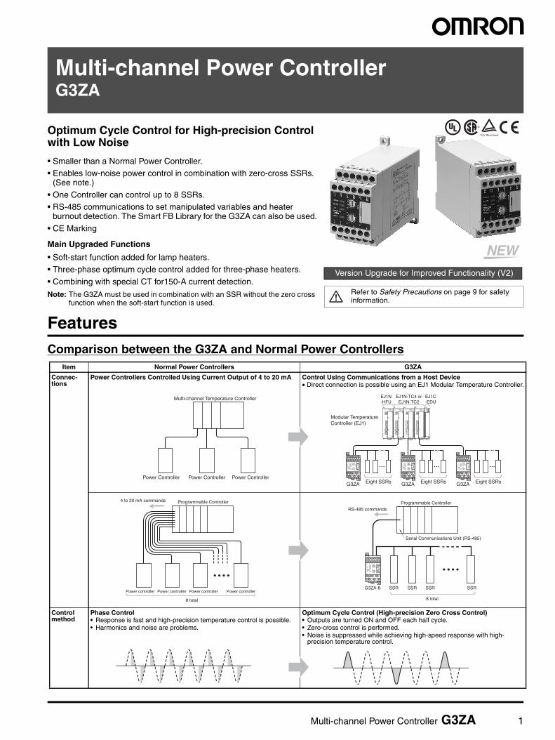
Optimum Cycle Control for High-precision Control with Low Noise
• Smaller than a Normal Power Controller.• Enables low-noise power control in combination with zero-cross SSRs.
(See note.)
• One Controller can control up to 8 SSRs.• RS-485 communications to set manipulated variables and heater
burnout detection. The Smart FB Library for the G3ZA can also be used.
• CE Marking
Main Upgraded Functions
• Soft-start function added for lamp heaters.• Three-phase optimum cycle control added for three-phase heaters.
• Combining with special CT for150-A current detection.
Note: The G3ZA must be used in combination with an SSR without the zero cross function when the soft-start function is used.
Version Upgrade for Improved Functionality (V2)
Refer to Safety Precautions on page 9 for safety information.
®
FeaturesComparison between the G3ZA and Normal Power Controllers
Item Normal Power Controllers G3ZA
Connec-tions
Power Controllers Controlled Using Current Output of 4 to 20 mA Control Using Communications from a Host Device • Direct connection is possible using an EJ1 Modular Temperature Controller.
Control method
Phase Control• Response is fast and high-precision temperature control is possible.• Harmonics and noise are problems.
Optimum Cycle Control (High-precision Zero Cross Control)• Outputs are turned ON and OFF each half cycle.• Zero-cross control is performed. • Noise is suppressed while achieving high-speed response with high-
precision temperature control.
Power Controller Power ControllerPower Controller
Multi-channel Temperature Controller EJ1N-HFU
EJ1N-TC4 orEJ1N-TC2
Modular Temperature Controller (EJ1)
EJ1C-EDU
COM1COM2COM3
PWRRUNERRALM
SW1
ON
SW2
21
34
56
78
EJ1-TC4
0123456789ABC
DEF
COM1COM2COM3
PWRRUNERRALM
SW1
ON
SW2
21
34
56
78
EJ1-TC4
0123456789ABC
DEF
COM1COM2COM3
PWRRUNERRALM
SW1
ON
SW2
21
34
56
78
EJ1-TC4
0123456789ABC
DEF
COM1COM2COM3
PWRRUNERRALM
SW1
ON
SW2
21
34
56
78
EJ1-HFU
0123456789ABC
DEF
SW2
SW1
ERROR
OCC
SD/RD
READY
SW2
SW1
ERROR
OCC
SD/RD
READY
SW2
SW1
ERROR
OCC
SD/RD
READY
G3ZA Eight SSRs G3ZA Eight SSRs G3ZA Eight SSRs
Power controller Power controller Power controller Power controller
8 total
Programmable Controller4 to 20 mA commands
G3ZA-8 SSR SSR SSR SSR
8 total
Programmable ControllerRS-485 commands
Serial Communications Unit (RS-485)

2 Multi-channel Power Controller G3ZA
Model Number Structure
Model Number Legend
Ordering Information
List of Models
Note: When using the heater burnout detection function, CTs must be ordered separately.
Accessories (Order Separately)
No. Meaning Code Specifications No. Meaning Code Specifications
1 No. of control points 4 4 channels 4 Load power supply voltage 2 100 to 240 VAC
8 8 channels 4 400 to 480 VAC
2 Control method None Optimum cycle control 5 Communications specifications 03 RS-485
3 Heater burnout detection H Yes 6 Communications protocol FLK CompoWay/F
A None 7 International standards UTU Approved by TÜV, UL, and CSA.
1 2 3 4
G3ZA- @ @ @ @ @ - @ - @5 6 7
Name Number of control channels Heater burnout detection Load power supply voltage Model
Multi-channel Power Controller
4 Supported 100 to 240 VAC G3ZA-4H203-FLK-UTU
400 to 480 VAC G3ZA-4H403-FLK-UTU
8 Not supported 100 to 240 VAC G3ZA-8A203-FLK-UTU
400 to 480 VAC G3ZA-8A403-FLK-UTU
Upgraded FunctionalityRefer to page 7 for details. Upgrade functions are marked with “V2”.
Name Hole diameter Detection current
Model
Current Transformer(CT)
5.8 dia. 0 to 50 A E54-CT1
12.0 dia. 0 to 50 A E54-CT3
30.0 dia. 0 to 150 A G3ZA-CT150L
Name Model
DIN Track PFP-100N
PFP-50N
End Plates (stoppers) PFP-M
Be sure to read the precautions for correct use and other precautions in the following user’s manual before using the Power Controller.G3ZA Multi-channel Power Controller User’s Manual (Cat. No. Z200)
Multi-channel Power Controller G3ZA 3
Specifications
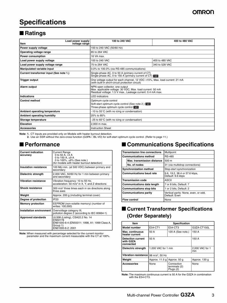
Ratings
Note: 1. CT inputs are provided only on Models with heater burnout detection. 2. Use an SSR without the zero-cross function (G3PA-@BL-VD) for soft-start optimum cycle control. (Refer to page 11.)
Performance
Note: When measured with percentage selected for the current monitor parameter and the maximum current measurable with the CT at 100%.
Communications Specifications
Current Transformer Specifications(Order Separately)
Note: The maximum continuous current is 50 A for the G3ZA in combination with the E54-CT3.
ItemLoad power supply
voltage range100 to 240 VAC 400 to 480 VAC
Power supply voltage 100 to 240 VAC (50/60 Hz)
Operating voltage range 85 to 264 VAC
Power consumption 16 VA max.
Load power supply voltage 100 to 240 VAC 400 to 480 VAC
Load power supply voltage range 75 to 264 VAC 340 to 528 VAC
Manipulated variable input 0.0% to 100.0% (via RS-485 communications)
Current transformer input (See note 1.) Single-phase AC, 0 to 50 A (primary current of CT)Single-phase AC, 0 to 150 A (primary current of CT)
Trigger output One voltage output for each channel, 12 VDC ±15%, Max. load current: 21 mA (with built-in short-circuit protection circuit)
Alarm output NPN open collector, one outputMax. applicable voltage: 30 VDC, Max. load current: 50 mAResidual voltage: 1.5 V max., Leakage current: 0.4 mA max.
Indications LED indicators
Control method Optimum cycle control Soft-start optimum cycle control (See note 2.) Three-phase optimum cycle control
Ambient operating temperature −10 to 55°C (with no icing or condensation)
Ambient operating humidity 25% to 85%
Storage temperature −25 to 65°C (with no icing or condensation)
Elevation 2,000 m max.
Accessories Instruction Sheet
V2
V2V2
Current indication accuracy
Current Range0 to 50 A, ±3 A 0 to 150 A, ±9 A0 to 100%, ±6% (See note.)
(for models with heater burnout detection)
Insulation resistance 100 MΩ min. (at 500 VDC) between primary and secondary
Dielectric strength 2,000 VAC, 50/60 Hz for 1 min between primary and secondary
Vibration resistance Vibration frequency: 10 to 55 Hz, acceleration: 50 m/s2 in X, Y, and Z directions
Shock resistance 300 m/s2 three times each in six directions along three axes
Weight Approx. 200 g (including terminal cover)
Degree of protection IP20
Memory protection EEPROM (non-volatile memory) (number of writes: 100,000)
Installation environment Overvoltage category III, pollution degree 2 (according to IEC 60664-1)
Approved standards UL508 (Listing), CSA22.2 No. 14EN50178EN61000-6-4 (EN55011: 1998, A1: 1999 Class A, Group 1) EN61000-6-2: 2001
Transmission line connections Multipoint
Communications method RS-485
Max. transmission distance 500 m
No. of nodes 31 (via multidrop connections)
Synchronization method Stop-start synchronization
Communications baud rate 9.6, 19.2, 38.4 or 57.6 kbps, Default: 9.6 kbps
Transmission code ASCII
Communications data length 7 or 8 bits, Default: 7
Communications stop bits 1 or 2 bits, Default: 2
Communications parity Vertical parity: None, even, or odd, Default: Even
Flow control None
Item Specification
Model number E54-CT1 E54-CT3 G3ZA-CT150L
Max. continuous heater current
50 A 120 A (See note.) 150 A
Detection current with G3ZA connected
50 A 150 A
Dielectric strength 1,000 VAC for 1 min 2,000 VAC for 1 min
Vibration resistance 98 m/s2, 50 Hz
Weight Approx. 11.5 g Approx. 50 g Approx. 130 g
Accessories None Connection terminals (2)Plugs (2)
None
4 Multi-channel Power Controller G3ZA
Applicable SSR and Control MethodsThe G3ZA can be used for a variety of applications by selecting the SSR drive. For example, inrush current can be reduced at startup by selecting soft-start optimum cycle control if a single-phase halogen heater is used.
Optimum Cycle Control• Optimum cycle control is performed by driving SSRs according to
load power detection and trigger signals. (Zero-cross SSRs are used.)
• Noise is suppressed while ensure high-speed response by turning outputs ON and OFF each half cycle to achieve high-precision temperature control.
Note: Refer to Connection Configuration on page 6 for connecting to an SSR.
Soft-start Optimum Cycle Control • Soft-start optimum cycle control is a control method that combines
phase control and optimum cycle control.• Smooth switching for phase control and optimum cycle control
enables control of outputs with limited inrush current even for loadswith characteristics like halogen heaters.
• Use a single-phase heater SSR (without the zero-cross function)for soft-start optimum cycle control. Refer to G3PA on page 11 fordetails on SSRs without the zero-cross function.
• Control is switched according to the Control Switching MV Thresh-old.
• Set the Soft-start Up/Down Time to control output.• Current is not detected during phase control. The current value
(heater ON current value, heater OFF current value, and effectivecurrent value) will be 0 A, and the current error alarm (heater burn-out detection, SSR short-circuit detection, and heater overcurrentdetection) will always turn OFF.
Setting the Control Switching MV ThresholdThe Control Switching MV Threshold function is enabled when soft-start optimum cycle control is used. Setting the Control Switching MV Threshold enables switching to phase control when the current value is below the set value, and switching to optimum cycle control when the current value is above the set value. The default setting is 20.0%.
Example: For channel 1, soft-start optimum cycle control is performed under the following conditions: control switching MV: 40.0%, MV: 100.%, soft startup time: 20 s.
(1) Ch 1 Control Switching MV Threshold is set to 40.0% and Ch1 MV is set to 100.0% by writing to the variable area.
(2) Ch1 Soft Startup Time remains at the default. Setting is not required.
(3) Once the Control Switching MV Threshold is written, the changes are saved and become enabled the next time the power is turned ON.
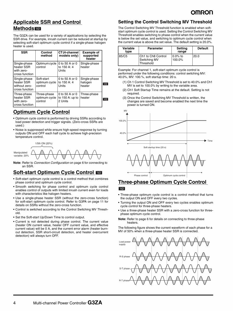
Three-phase Optimum Cycle Control
• Three-phase optimum cycle control is a control method that turnsthe output ON and OFF every two cycles.
• Turning the output ON and OFF every two cycles enables optimumcycle control for three-phase heaters.
• Use a three-phase heater SSR with a zero-cross function for three-phase optimum cycle control.
Note: Refer to page 6 for details on connecting to three-phase heaters.
The following figure shows the current waveform of each phase for a MV of 50% when a three-phase heater SSR is connected.
SSR Control method
CT (4-channel models only)
Example of supported
heater
Single-phase heater SSR with zero-cross function
Optimum cycle control
0 to 50 A or 0 to 150 A: 4 Units
SIngle-phase heater
Single-phase heater SSR without zero-cross function
Soft-start optimum cycle control
0 to 50 A or 0 to 150 A: 4 Units
Single-phase halogen heater
Three-phase heater SSR with zero-cross function
Three-phase optimum cycle control
0 to 50 A or 0 to 150 A: up to 2 Units
Three-phase heater
V2
V2
V2
1/5th ON (20%)
Manipulatedvariable: 20%
V2
Variable type
Parameter Setting range
Default
85/C5 Ch1 to Ch8 Control Switching MV Threshold
0.0% to 100.0%
20.0
Phase control Optimum cycle control
Soft startup time (20 s)
100.0%
MV
Time
40.0%
V2
Load power supply
R-S phase
S-T phase
R-T phase
Multi-channel Power Controller G3ZA 5
Connections
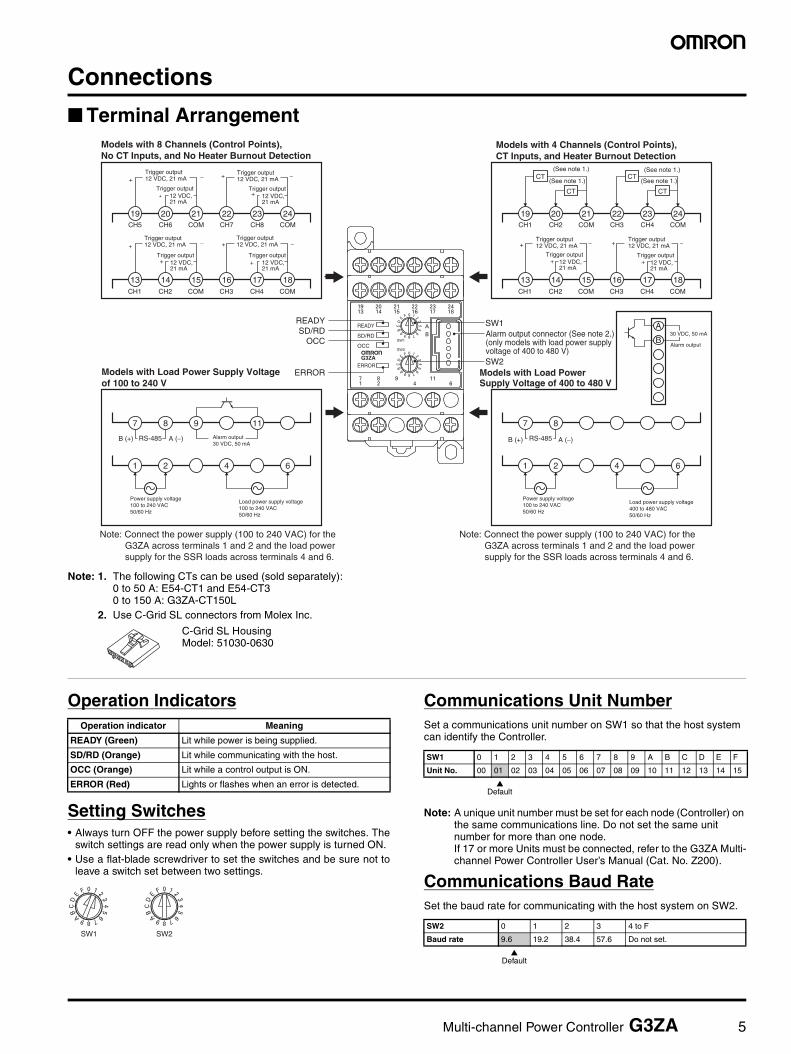
Terminal Arrangement
Note: 1. The following CTs can be used (sold separately): 0 to 50 A: E54-CT1 and E54-CT30 to 150 A: G3ZA-CT150L
2. Use C-Grid SL connectors from Molex Inc.
Operation Indicators
Setting Switches• Always turn OFF the power supply before setting the switches. The
switch settings are read only when the power supply is turned ON. • Use a flat-blade screwdriver to set the switches and be sure not to
leave a switch set between two settings.
Communications Unit NumberSet a communications unit number on SW1 so that the host system can identify the Controller.
Note: A unique unit number must be set for each node (Controller) on the same communications line. Do not set the same unit number for more than one node. If 17 or more Units must be connected, refer to the G3ZA Multi-channel Power Controller User’s Manual (Cat. No. Z200).
Communications Baud RateSet the baud rate for communicating with the host system on SW2.
+
+
+
+
−
+
+
+−
+
−
+
+
+−
+
−
Trigger output12 VDC, 21 mA
Trigger output12 VDC, 21 mA
Trigger output12 VDC, 21 mA
Trigger output12 VDC, 21 mA
Models with 8 Channels (Control Points), No CT Inputs, and No Heater Burnout Detection
Trigger output12 VDC, 21 mA
Models with 4 Channels (Control Points), CT Inputs, and Heater Burnout Detection
Trigger output12 VDC, 21 mA
Alarm output30 VDC, 50 mA
Power supply voltage100 to 240 VAC50/60 Hz
Load power supply voltage 100 to 240 VAC50/60 Hz
Models with Load Power Supply Voltage of 100 to 240 V
Power supply voltage100 to 240 VAC50/60 Hz
Models with Load Power Supply Voltage of 400 to 480 V
Load power supply voltage 400 to 480 VAC50/60 Hz
19 20 21 22 23 24CH5 CH6 COM CH7 CH8 COM CH1 CH2 COM CH3 CH4 COM
13 14 15 16 17 18CH1 CH2 COM CH3 CH4 COM CH1 CH2 COM CH3 CH4 COM
19 20 21 22 23 24
13 14 15 16 17 18
CT
CT
CT
CT
7
B (+) A (−)RS-485
8 9 11
1 2 4 6
7
RS-485
8
1 2 4 6
B
A
SW2
SW1
ERROR
OCC
SD/RD
READY
ERROR
OCCSD/RD
READY SW1
SW2
−
B (+) A (−)
(See note 1.) (See note 1.)
(See note 1.) (See note 1.)
Alarm output connector (See note 2.)(only models with load power supply voltage of 400 to 480 V)
Note: Connect the power supply (100 to 240 VAC) for the G3ZA across terminals 1 and 2 and the load power supply for the SSR loads across terminals 4 and 6.
Note: Connect the power supply (100 to 240 VAC) for the G3ZA across terminals 1 and 2 and the load power supply for the SSR loads across terminals 4 and 6.
30 VDC, 50 mA
Alarm output
Trigger output12 VDC, 21 mA
Trigger output12 VDC, 21 mA
Trigger output12 VDC, 21 mA
Trigger output12 VDC, 21 mA
Trigger output12 VDC, 21 mA
Trigger output12 VDC, 21 mA
C-Grid SL HousingModel: 51030-0630
Operation indicator Meaning
READY (Green) Lit while power is being supplied.
SD/RD (Orange) Lit while communicating with the host.
OCC (Orange) Lit while a control output is ON.
ERROR (Red) Lights or flashes when an error is detected.
SW1 SW2
SW1 0 1 2 3 4 5 6 7 8 9 A B C D E F
Unit No. 00 01 02 03 04 05 06 07 08 09 10 11 12 13 14 15
Default
SW2 0 1 2 3 4 to F
Baud rate 9.6 19.2 38.4 57.6 Do not set.
Default

6 Multi-channel Power Controller G3ZA
Connection ConfigurationSingle-phase SSR
Note: Connect a power supply with the same phase as the SSRs to the load power supply terminals on the G3ZA.
Three-phase SSR
Note: Connect to one of the three phases on the load power supply input terminals of the G3ZA.
Host Device Connection ExampleExample of Connection to EJ1 Modular Temperature Controller
Example of Connection to PLC
Trigger signal
G3ZA
Example for Connecting Two SSRs
R phase
S phase
T phase
Host device
Control power supply
SSR
CT (4-channel model only)
SSR
Load(e.g., heater)
Load(e.g., heater)
Load power supply
V2
G3ZA
R phase
S phase
T phase
Host device
Control power supply
Load
Trigger signal
SSR(three-phase)
CT (4-channel model only)
Load powersupply
Eight SSRs Eight SSRs Eight SSRs
SW2
SW1
ERROR
OCC
SD/RD
READY
G3ZA
PC
PLC PTPC
EJ1N-TC4or
EJ1N-TC2 EJ1C-EDU
Port A (connector): USB connection possible using a E58-CIFQ1 (sold separately)
Port B: RS-485 (CompoWay/F)
COM1COM2COM3
PWRRUNERRALM
SW1
ON
SW2
21
34
56
78
EJ1-TC4
0123456789ABC
DEF
COM1COM2COM3
PWRRUNERRALM
SW1
ON
SW2
21
34
56
78
EJ1-TC4
0123456789ABC
DEF
COM1COM2COM3
PWRRUNERRALM
SW1
ON
SW2
21
34
56
78
EJ1-TC4
0123456789ABC
DEF
SW2
SW1
ERROR
OCC
SD/RD
READY
SW2
SW1
ERROR
OCC
SD/RD
READY
G3ZAG3ZA
Host Devices
G3ZAConnection port
G3ZAConnection port
G3ZAConnection port
CX-Thermo for setup
PLC
Alarm output
Load power supply(for zero-cross detection)
Power supply for Multi-channel Power Controller
RS-485
Heater
G3ZA SSR

Multi-channel Power Controller G3ZA 7
Upgraded Functions Upgraded Functions1. Added soft-start optimum cycle control.2. Added three-phase optimum cycle control.3. Increased heater burnout detection to 150 A.4. Achieved effective current value monitoring.5. Changed current error detection from a fixed value to a variable value.6. Changed detection time unit to seconds for communications errors.
New functions are marked with “V2”.
Identifying Upgraded ModelsCheck the label on the Power Controller or the box to determine the version. Models not marked “Ver. 2.0” are version 1.0.
Box Label Power Controller Label
DimensionsNote: All units are in millimeters unless otherwise indicated.
Multi-channel Power Controllers
V2
V2
Version
OMRON Corporation MADE IN JAPAN
Version
Mounting Hole Dimensions(For Direct Mounting)
4.6 dia.
111 max.(TYP. 110)
7 × 5 = 35 Two, 4.2 dia. or M4
SW2
SW1
ERROR
OCC
SD/RD
READY
915.3
9
9
76 max.63
84
5.6
43
35±0.3
45 max.
R 2.3
R 4.5
35±0.3
84±0.3
G3ZA-4H203-FLK-UTUG3ZA-4H403-FLK-UTUG3ZA-8A203-FLK-UTUG3ZA-8A403-FLK-UTU

8 Multi-channel Power Controller G3ZA
Accessories (Order Separately)
30
21
155.8 dia.
25 3
40
10.5
2.8
7.5
10
Two, 3.5 dia.
Current Transformer (CT)
E54-CT1
40 × 40
30
12 dia.
9
2.36 dia.
15
30
Two, M3 (depth: 4)
Approx. 3 dia.
18
(22)
Approx. 6 dia.
PlugContactor
Lead
E54-CT3 Accessories
• Contactors
• Plugs
Current Transformer (CT)
E54-CT3
1.8
764.1
1010
5.9
5.2
20
Two M5 screw holes or two 5.5-dia. holes
57 30 dia.14.514.5
6
8.5
50
33.5
34.581.5
13.5
86
5463
114.7
Four, M4 × 6 screws17
20
26 max.
9.3
1.71.7
9.3
76
Mounting Hole Dimensions
Current Transformer (CT)
G3ZA-CT150L
Note: The G3ZA-CT150L is for use only in combination with the G3ZA.Wire terminal k and terminal l. (Do not use terminal kt and terminal lt.)
4.5
15 25 2510 10
1,000 (500)*
25 25 15 (5)*
35±0.3
7.3±0.15
27±0.15
1
* Dimensions in parentheses are for the PFP-50N.
DIN Track
PFP-100NPFP-50N
50
11.5
10
M4 x 8pan-headscrew
M4 spring washer
4.81.3
1.8
1
10
6.21.8
35.5 35.3
End Plate (Stopper)
PFP-M
Multi-channel Power Controller G3ZA 9
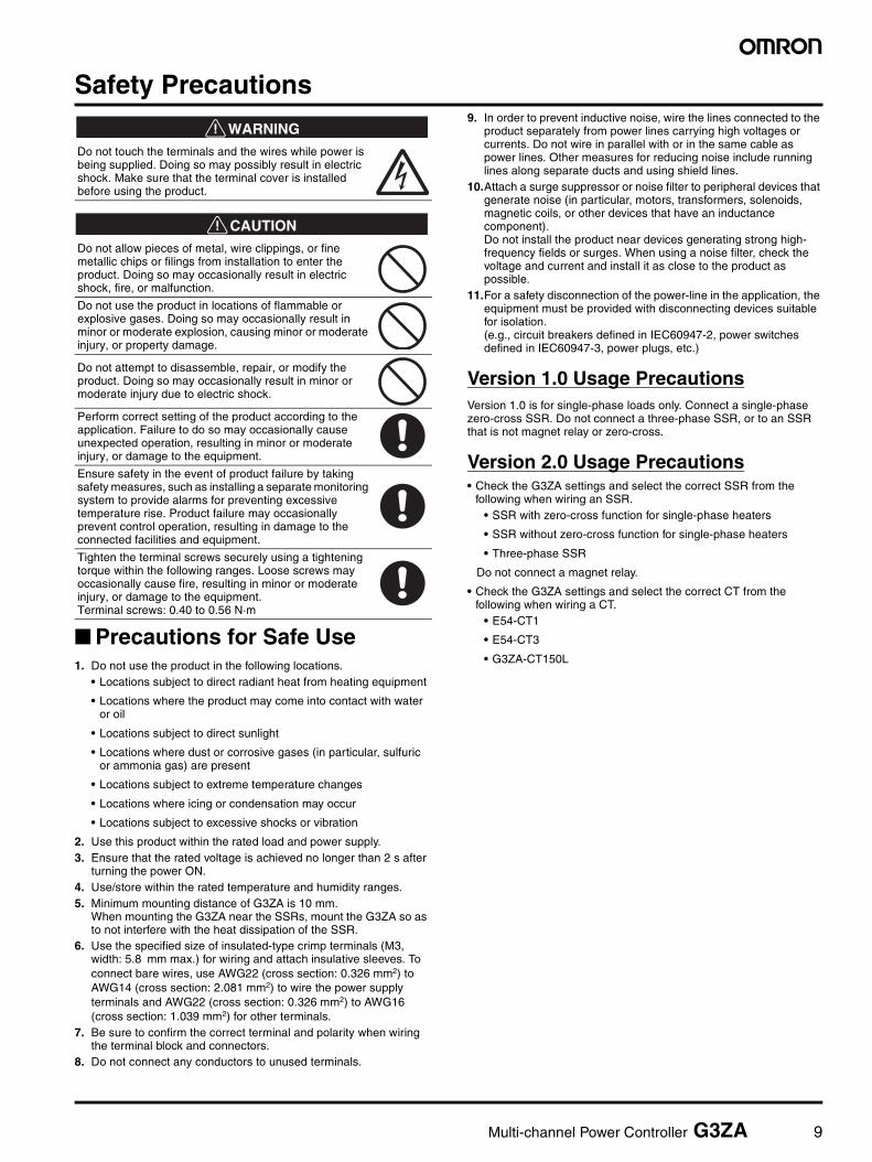
Safety Precautions
!WARNING
!CAUTION
Precautions for Safe Use1. Do not use the product in the following locations.
• Locations subject to direct radiant heat from heating equipment
• Locations where the product may come into contact with water or oil
• Locations subject to direct sunlight
• Locations where dust or corrosive gases (in particular, sulfuric or ammonia gas) are present
• Locations subject to extreme temperature changes
• Locations where icing or condensation may occur
• Locations subject to excessive shocks or vibration
2. Use this product within the rated load and power supply.3. Ensure that the rated voltage is achieved no longer than 2 s after
turning the power ON.4. Use/store within the rated temperature and humidity ranges.5. Minimum mounting distance of G3ZA is 10 mm.
When mounting the G3ZA near the SSRs, mount the G3ZA so as to not interfere with the heat dissipation of the SSR.
6. Use the specified size of insulated-type crimp terminals (M3, width: 5.8 mm max.) for wiring and attach insulative sleeves. To connect bare wires, use AWG22 (cross section: 0.326 mm2) to AWG14 (cross section: 2.081 mm2) to wire the power supply terminals and AWG22 (cross section: 0.326 mm2) to AWG16 (cross section: 1.039 mm2) for other terminals.
7. Be sure to confirm the correct terminal and polarity when wiring the terminal block and connectors.
8. Do not connect any conductors to unused terminals.
9. In order to prevent inductive noise, wire the lines connected to the product separately from power lines carrying high voltages or currents. Do not wire in parallel with or in the same cable as power lines. Other measures for reducing noise include running lines along separate ducts and using shield lines.
10.Attach a surge suppressor or noise filter to peripheral devices that generate noise (in particular, motors, transformers, solenoids, magnetic coils, or other devices that have an inductance component).Do not install the product near devices generating strong high-frequency fields or surges. When using a noise filter, check the voltage and current and install it as close to the product as possible.
11.For a safety disconnection of the power-line in the application, the equipment must be provided with disconnecting devices suitable for isolation.(e.g., circuit breakers defined in IEC60947-2, power switches defined in IEC60947-3, power plugs, etc.)
Version 1.0 Usage PrecautionsVersion 1.0 is for single-phase loads only. Connect a single-phase zero-cross SSR. Do not connect a three-phase SSR, or to an SSR that is not magnet relay or zero-cross.
Version 2.0 Usage Precautions• Check the G3ZA settings and select the correct SSR from the
following when wiring an SSR. • SSR with zero-cross function for single-phase heaters
• SSR without zero-cross function for single-phase heaters
• Three-phase SSR
Do not connect a magnet relay.
• Check the G3ZA settings and select the correct CT from the following when wiring a CT.
• E54-CT1
• E54-CT3
• G3ZA-CT150L
Do not touch the terminals and the wires while power is being supplied. Doing so may possibly result in electric shock. Make sure that the terminal cover is installed before using the product.
Do not allow pieces of metal, wire clippings, or fine metallic chips or filings from installation to enter the product. Doing so may occasionally result in electric shock, fire, or malfunction.
Do not use the product in locations of flammable or explosive gases. Doing so may occasionally result in minor or moderate explosion, causing minor or moderate injury, or property damage.
Do not attempt to disassemble, repair, or modify the product. Doing so may occasionally result in minor or moderate injury due to electric shock.
Perform correct setting of the product according to the application. Failure to do so may occasionally cause unexpected operation, resulting in minor or moderate injury, or damage to the equipment.
Ensure safety in the event of product failure by taking safety measures, such as installing a separate monitoring system to provide alarms for preventing excessive temperature rise. Product failure may occasionally prevent control operation, resulting in damage to the connected facilities and equipment.
Tighten the terminal screws securely using a tightening torque within the following ranges. Loose screws may occasionally cause fire, resulting in minor or moderate injury, or damage to the equipment.Terminal screws: 0.40 to 0.56 N·m

10 Multi-channel Power Controller G3ZA
Precautions for Correct UseWiringUse M3 crimp terminals.
Use wires that withstand a minimum of 70°C.
DIN TrackSecure the DIN Track with screws in at least three locations.
DIN Track: PFP-50N (50 cm)/PFP-100N (100 cm)
Mounting the G3ZAMount the G3ZA as shown in the diagram. First, pull down the DIN Track mounting hook (1) and hook the top of the G3ZA on the DIN Track (2). Then press the G3ZA onto the DIN Track far enough so that it can be locked in place (3) and push the DIN Track mounting hook up to lock the G3ZA in place (4).
Removing the G3ZAUse a flat-blade screwdriver to pull down the DIN Track mounting hook (1) and then pull out on the bottom of the G3ZA (2).
Mounting End PlatesBe sure to mount an End Plate on each side of the G3ZA so that it does not slide on the DIN Track.
To mount an End Plate, hook the bottom of the End Plate on the bottom of the DIN Track (1), place the top of the End Plate on the DIN Track (2), and then pull down on the End Plate. Tighten the screw on the End Plate to secure it.
Note: Always mount one End Plate on each side of the G3ZA.
Installation ExampleWhen installing the SSRs next to the G3ZA, provide sufficient space between the G3ZA and SSRs, as shown in the following diagram.
Reference example: When applying 25 A to the G3PB-225B-VD (a manipulated variable of 100%), separate the SSRs from the G3ZA by at least 50 mm.
Do not touch the G3ZA while power is being supplied.
Mounting with Screws
Mounting Dimensions (Unit: mm)
5.8 mm max.
5.8 mm max.
(4)
(3)
(2)
(1)
(1)
(2)
ΣΩ2
ΣΩ1
ΕΡΡΟΡ
ΟΧΧ
Σ∆/Ρ∆
ΡΕΑ∆Ψ
(1)
(2)
End Plate End Plate
SW2
SW1
ERROR
OCC
SD/RD
READY
50 mm min. 50 mm min.
SSR G3ZA SSR
35±0.3
84±0.3
Two, 4.2 dia. or M4
Solid State Relays G3PA 11
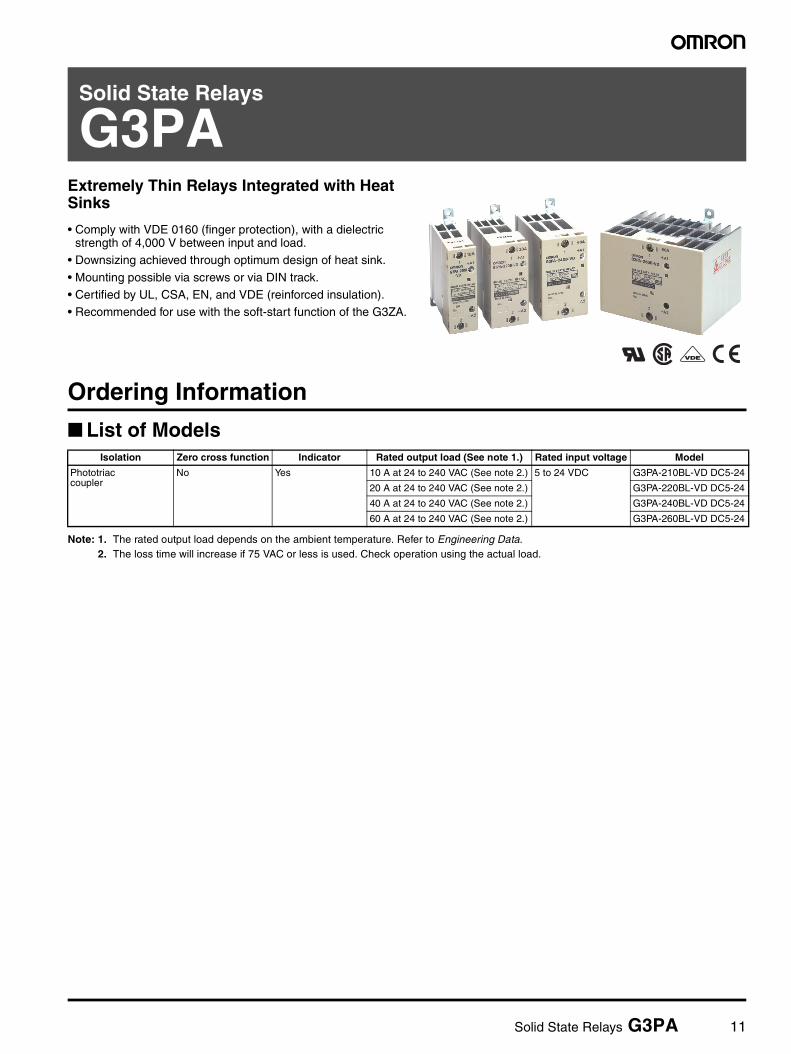
Solid State Relays
G3PAExtremely Thin Relays Integrated with Heat Sinks
• Comply with VDE 0160 (finger protection), with a dielectric strength of 4,000 V between input and load.
• Downsizing achieved through optimum design of heat sink.
• Mounting possible via screws or via DIN track.• Certified by UL, CSA, EN, and VDE (reinforced insulation).• Recommended for use with the soft-start function of the G3ZA.
Ordering Information
List of Models
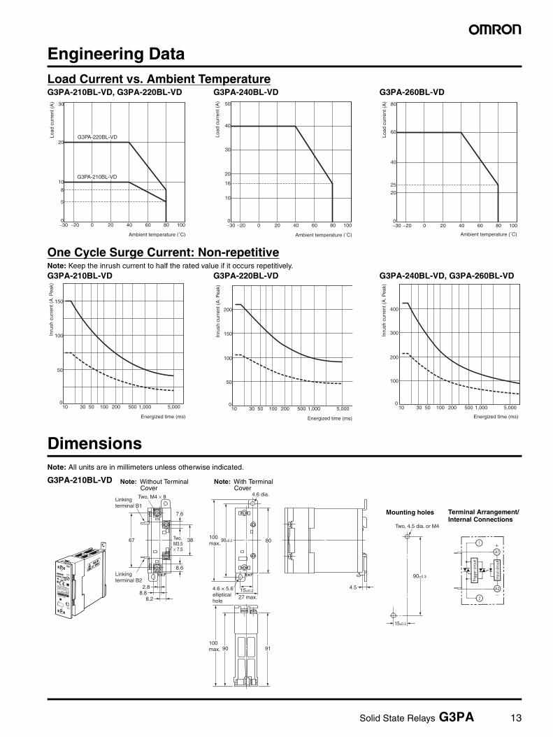
Note: 1. The rated output load depends on the ambient temperature. Refer to Engineering Data.2. The loss time will increase if 75 VAC or less is used. Check operation using the actual load.
Isolation Zero cross function Indicator Rated output load (See note 1.) Rated input voltage Model
Phototriac coupler
No Yes 10 A at 24 to 240 VAC (See note 2.) 5 to 24 VDC G3PA-210BL-VD DC5-24
20 A at 24 to 240 VAC (See note 2.) G3PA-220BL-VD DC5-24
40 A at 24 to 240 VAC (See note 2.) G3PA-240BL-VD DC5-24
60 A at 24 to 240 VAC (See note 2.) G3PA-260BL-VD DC5-24
12 Solid State Relays G3PA
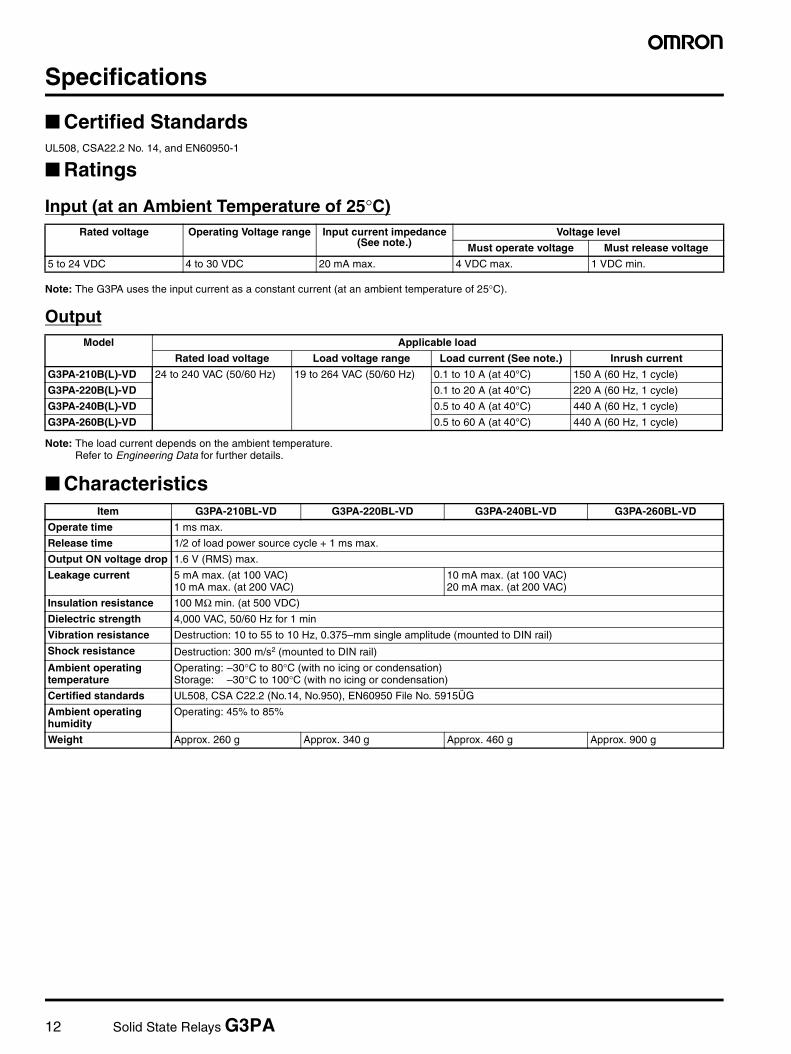
Specifications
Certified StandardsUL508, CSA22.2 No. 14, and EN60950-1
Ratings
Input (at an Ambient Temperature of 25°C)
Note: The G3PA uses the input current as a constant current (at an ambient temperature of 25°C).
Output
Note: The load current depends on the ambient temperature. Refer to Engineering Data for further details.
Characteristics
Rated voltage Operating Voltage range Input current impedance(See note.)
Voltage level
Must operate voltage Must release voltage
5 to 24 VDC 4 to 30 VDC 20 mA max. 4 VDC max. 1 VDC min.
Model Applicable load
Rated load voltage Load voltage range Load current (See note.) Inrush current
G3PA-210B(L)-VD 24 to 240 VAC (50/60 Hz) 19 to 264 VAC (50/60 Hz) 0.1 to 10 A (at 40°C) 150 A (60 Hz, 1 cycle)
G3PA-220B(L)-VD 0.1 to 20 A (at 40°C) 220 A (60 Hz, 1 cycle)
G3PA-240B(L)-VD 0.5 to 40 A (at 40°C) 440 A (60 Hz, 1 cycle)
G3PA-260B(L)-VD 0.5 to 60 A (at 40°C) 440 A (60 Hz, 1 cycle)
Item G3PA-210BL-VD G3PA-220BL-VD G3PA-240BL-VD G3PA-260BL-VD
Operate time 1 ms max.
Release time 1/2 of load power source cycle + 1 ms max.
Output ON voltage drop 1.6 V (RMS) max.
Leakage current 5 mA max. (at 100 VAC)10 mA max. (at 200 VAC)
10 mA max. (at 100 VAC)20 mA max. (at 200 VAC)
Insulation resistance 100 MΩ min. (at 500 VDC)
Dielectric strength 4,000 VAC, 50/60 Hz for 1 min
Vibration resistance Destruction: 10 to 55 to 10 Hz, 0.375–mm single amplitude (mounted to DIN rail)
Shock resistance Destruction: 300 m/s2 (mounted to DIN rail)
Ambient operating temperature
Operating: –30°C to 80°C (with no icing or condensation)Storage: –30°C to 100°C (with no icing or condensation)
Certified standards UL508, CSA C22.2 (No.14, No.950), EN60950 File No. 5915ÜG
Ambient operating humidity
Operating: 45% to 85%
Weight Approx. 260 g Approx. 340 g Approx. 460 g Approx. 900 g
Solid State Relays G3PA 13
Engineering Data
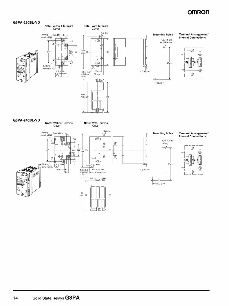
DimensionsNote: All units are in millimeters unless otherwise indicated.
Load Current vs. Ambient TemperatureG3PA-210BL-VD, G3PA-220BL-VD G3PA-240BL-VD G3PA-260BL-VD
One Cycle Surge Current: Non-repetitiveNote: Keep the inrush current to half the rated value if it occurs repetitively.G3PA-210BL-VD G3PA-220BL-VD G3PA-240BL-VD, G3PA-260BL-VD
30
20
10
8
5
0100806040200−20−30
Ambient temperature (˚C)
G3PA-220BL-VD
G3PA-210BL-VD
Load
cur
rent
(A
) 50
40
30
20
10
16
0100806040200−20−30
Ambient temperature (˚C)
Load
cur
rent
(A
) 80
60
40
20
25
0100 806040200−20−30
Ambient temperature (˚C)
Load
cur
rent
(A
)
150
100
50
05,0001,000500200100503010
Energized time (ms)
Inru
sh c
urre
nt (
A. P
eak)
200
150
100
50
05,0001,000500200100503010
Energized time (ms)
Inru
sh c
urre
nt (
A. P
eak)
400
300
200
100
05,0001,000500200100503010
Energized time (ms)
Inru
sh c
urre
nt (
A. P
eak)
Linkingterminal B1
Two, M4 × 8
Linkingterminal B2
Two,M3.5× 7.5
67
15±0.2
4.6 dia.
4.6 × 5.6ellipticalhole
100max.
100max. 90 91
38 90±0.2 80
8.6
2.88.8
8.2
7.6
27 max.
4.5
Two, 4.5 dia. or M4
90±0.3
15±0.3
Trig
ger
circ
uit
Inpu
t circ
uit
G3PA-210BL-VD Note: Without Terminal Cover
Note: With Terminal Cover
Mounting holes Terminal Arrangement/Internal Connections
14 Solid State Relays G3PA
Linkingterminal B1
Two, M4 × 8
Linking terminal B2
Two,M3.5× 7.5
67
25±0.2
4.6 dia.
4.6 × 5.6elliptical hole
100 max.
100 max. 90 91
38 90±0.2 80
8.6
2.28.813.2
7.6
37 max.4.5
Two, 4.5 dia. or M4 holes
90±0.3
25±0.3
Trig
ger
circ
uit
Inpu
t circ
uit
Mounting holes
Note: Without Terminal Cover
Note: With Terminal Cover
G3PA-220BL-VD
Terminal Arrangement/Internal Connections
Linkingterminal B1
Two, M5 × 12
Linking terminal B2
Two,M3.5× 7.5
67
35±0.2
4.6 dia.
4.6 × 5.6elliptical hole
100 max.
100 max. 89 91
38 90±0.2 80
13
1318
7.6
47 max.4.5
Two, 4.5 dia. or M4
90±0.3
35±0.3
Trig
ger
circ
uit
Inpu
t circ
uit
Mounting holes
G3PA-240BL-VD
Terminal Arrangement/Internal Connections
Note: Without Terminal Cover
Note: With Terminal Cover

Solid State Relays G3PA 15
Two, M5 × 12 Two, M3.5 × 7.5
67
35±0.2
4.6 dia.
4.6 × 5.6elliptical hole
100max.
100max. 89 91
38 90±0.2 80
13
1318
7.6
110 max.4.5
Two, 4.5 dia. or M4
90±0.3
35±0.3
A1
A2
1
2
Trig
ger
circ
uit
Inpu
t circ
uit
G3PA-260BL-VD
Terminal Arrangement/Internal Connections
Mounting holesNote: Without Terminal Cover Note: With Terminal Cover
16 Solid State Relays G3PA
Safety Precautions
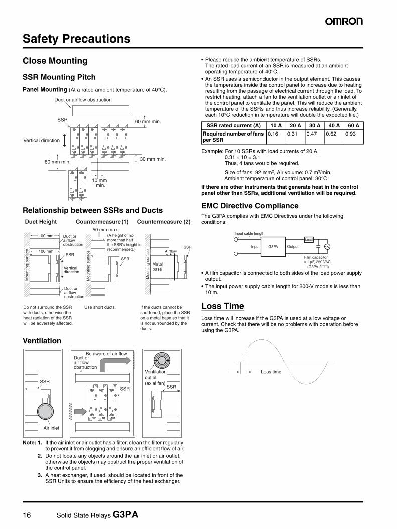
Close Mounting
SSR Mounting Pitch
Panel Mounting (At a rated ambient temperature of 40°C).
Relationship between SSRs and Ducts
Ventilation
Note: 1. If the air inlet or air outlet has a filter, clean the filter regularly to prevent it from clogging and ensure an efficient flow of air.
2. Do not locate any objects around the air inlet or air outlet, otherwise the objects may obstruct the proper ventilation of the control panel.
3. A heat exchanger, if used, should be located in front of the SSR Units to ensure the efficiency of the heat exchanger.
• Please reduce the ambient temperature of SSRs.The rated load current of an SSR is measured at an ambient operating temperature of 40°C.
• An SSR uses a semiconductor in the output element. This causes the temperature inside the control panel to increase due to heating resulting from the passage of electrical current through the load. To restrict heating, attach a fan to the ventilation outlet or air inlet of the control panel to ventilate the panel. This will reduce the ambient temperature of the SSRs and thus increase reliability. (Generally, each 10°C reduction in temperature will double the expected life.)
Example: For 10 SSRs with load currents of 20 A, 0.31 × 10 = 3.1Thus, 4 fans would be required.
Size of fans: 92 mm2, Air volume: 0.7 m3/min, Ambient temperature of control panel: 30°C
If there are other instruments that generate heat in the control panel other than SSRs, additional ventilation will be required.
EMC Directive ComplianceThe G3PA complies with EMC Directives under the following conditions.
• A film capacitor is connected to both sides of the load power supply output.
• The input power supply cable length for 200-V models is less than 10 m.
Loss TimeLoss time will increase if the G3PA is used at a low voltage or current. Check that there will be no problems with operation before using the G3PA.
SSR 60 mm min.
Vertical direction
30 mm min.80 mm min.
min.
Duct or airflow obstruction
SSR
SSR
SSR
Mou
ntin
g su
rfac
e
Mou
ntin
g su
rfac
e
Mou
ntin
g su
rfac
e
Duct or airflow obstruction
Duct orairflow obstruction
Vertical direction
Airflow
(A height of no more than halfthe SSR's height isrecommended.)
Duct Height
If the ducts cannot be shortened, place the SSR on a metal base so that it is not surrounded by the ducts.
Use short ducts. Do not surround the SSR with ducts, otherwise the heat radiation of the SSR will be adversely affected.
Countermeasure (1) Countermeasure (2) 50 mm max.
SSR SSRSSR
Air inlet
Be aware of air flowDuct or air flow obstruction
Ventilation outlet(axial fan)
SSR rated current (A) 10 A 20 A 30 A 40 A 60 A
Required number of fans per SSR
0.16 0.31 0.47 0.62 0.93
OutputInput G3PA
Load
Input cable length
Film capacitor• 1 µF, 250 VAC (G3PA-2@@)
Loss time

Solid State Relays G3PA 17

18 Solid State Relays G3PA

Solid State Relays G3PA 19

In the interest of product improvement, specifications are subject to change without notice.
ALL DIMENSIONS SHOWN ARE IN MILLIMETERS.To convert millimeters into inches, multiply by 0.03937. To convert grams into ounces, multiply by 0.03527.
Cat. No. J147-E1-02A
0107 (0604)
OMRON CorporationIndustrial Automation Company
Control Devices Division H.Q.Analog Controller DivisionShiokoji Horikawa, Shimogyo-ku,Kyoto, 600-8530 JapanTel: (81)75-344-7080/Fax: (81)75-344-7189
Warranty and Application ConsiderationsWarranty and Limitations of Liability
WARRANTYOMRON's exclusive warranty is that the products are free from defects in materials and workmanship for a period of one year (or other period if specified) from date of sale by OMRON.OMRON MAKES NO WARRANTY OR REPRESENTATION, EXPRESS OR IMPLIED, REGARDING NON-INFRINGEMENT, MERCHANTABILITY, OR FITNESS FOR PARTICULAR PURPOSE OF THE PRODUCTS. ANY BUYER OR USER ACKNOWLEDGES THAT THE BUYER OR USER ALONE HAS DETERMINED THAT THE PRODUCTS WILL SUITABLY MEET THE REQUIREMENTS OF THEIR INTENDED USE. OMRON DISCLAIMS ALL OTHER WARRANTIES, EXPRESS OR IMPLIED.
LIMITATIONS OF LIABILITYOMRON SHALL NOT BE RESPONSIBLE FOR SPECIAL, INDIRECT, OR CONSEQUENTIAL DAMAGES, LOSS OF PROFITS, OR COMMERCIAL LOSS IN ANY WAY CONNECTED WITH THE PRODUCTS, WHETHER SUCH CLAIM IS BASED ON CONTRACT, WARRANTY, NEGLIGENCE, OR STRICT LIABILITY.In no event shall the responsibility of OMRON for any act exceed the individual price of the product on which liability is asserted.IN NO EVENT SHALL OMRON BE RESPONSIBLE FOR WARRANTY, REPAIR, OR OTHER CLAIMS REGARDING THE PRODUCTS UNLESS OMRON'S ANALYSIS CONFIRMS THAT THE PRODUCTS WERE PROPERLY HANDLED, STORED, INSTALLED, AND MAINTAINED AND NOT SUBJECT TO CONTAMINATION, ABUSE, MISUSE, OR INAPPROPRIATE MODIFICATION OR REPAIR.
Application Considerations
SUITABILITY FOR USEOMRON shall not be responsible for conformity with any standards, codes, or regulations that apply to the combination of products in the customer's application or use of the products.Take all necessary steps to determine the suitability of the product for the systems, machines, and equipment with which it will be used.Know and observe all prohibitions of use applicable to this product.NEVER USE THE PRODUCTS FOR AN APPLICATION INVOLVING SERIOUS RISK TO LIFE OR PROPERTY WITHOUT ENSURING THAT THE SYSTEM AS A WHOLE HAS BEEN DESIGNED TO ADDRESS THE RISKS, AND THAT THE OMRON PRODUCTS ARE PROPERLY RATED AND INSTALLED FOR THE INTENDED USE WITHIN THE OVERALL EQUIPMENT OR SYSTEM.
Disclaimers
CHANGE IN SPECIFICATIONSProduct specifications and accessories may be changed at any time based on improvements and other reasons. Consult with your OMRON representative at any time to confirm actual specifications of purchased product.
DIMENSIONS AND WEIGHTSDimensions and weights are nominal and are not to be used for manufacturing purposes, even when tolerances are shown.
Recommended