MPLS VPNs: Layer 2 or Layer 3?Understanding the Choice
#128TECHNOLOGYWHITE PAPER
ABSTRACT
Tim Wu, Riverstone Networks
Since there’s been data networking, there’s been a debate between switched and routed architectures —stated in OSI terms, between performing functions at Layer 3 or Layer 2. Today, we see it again surfacingas network architects consider the design of Virtual Private Networks (VPNs) that take advantage ofMulti-Protocol Label Switching (MPLS). The question is, when are MPLS VPNs better implemented atLayer 3, using BGP-based VPNs, and when at Layer 2, using MPLS tunneling technologies?
The goal of this paper is to explain, in detail, what underlies the choice between Layer 2 and Layer 3MPLS VPNs. Neither will always be the "right" choice for every service provider — the nature of existingnetwork architectures and desired service offerings are what ultimately decide the matter. And, of course,some service providers may deploy both types of VPN, or salutary combinations of the two technologies.
For many (though not all) carriers, the complexity and expense of a Layer 3 MPLS VPN will be overkill.Layer 3 MPLS VPNs will likely remain most appealing to Internet Service Providers that already useBGP extensively and have already deployed high-end IP/MPLS routing equipment at the edge.However, for carriers with existing Layer 2 VPN deployments or those accustomed to delivering transport services, Layer 2’s MPLS "overlay" model should prove much more attractive. This followsbecause such carriers are unlikely to be interested in the degree of IP routing and (more to the point)high-end IP-equipment expenditures that Layer 3 VPNs call for. In addition, it is clear that where directinteroperability with existing Layer 2 VPN deployments is important, Layer 2 VPNs have the advantage.
Riverstone’s MPLS interfaces currently offer complete Layer 2 VPN solutions based on Martini-draft tunneling and various extensions. Riverstone MPLS routers can also form part of a Layer 3 MPLS RFC 2547 VPN network, and the company plays a leading role in developing joint Layer 2/Layer 3 VPN solutions.
This paper introduces (1) VPN basics, (2) the Layer 3 "Private Routed Network" VPN approach, (3) the Layer 2 Martini approach, and (4) which network suits whom.
Page: 1 of 6

Page: 2 of 6# 128 TECHNOLOGY WHITE PAPER
THE BASICS
THE LAYER 3 APPROACH
It is easy to lose sight of the purpose of MPLS VPN technology in the first place. The goal is simple:to build a network that, as much as possible, acts like an extension of the private corporate networkon a service provider’s shared network infrastructure. The result, ideally, is a fast and efficient meansof making scattered places seem just like local sites, from workers’ homes to branch offices.
MPLS, designed to scale IP networks, is a natural choice for virtual private networks. Supporting multiple private networks on a shared infrastructure suggests immediate scaling problems for bothLayer 3 and Layer 2 networks. On a Layer 3 network, asking each router on the network to potentiallysupport thousands of different routing tables (one for each virtual private network, in addition to thoseof the public network) is an interminable option. Layer 2 networks, on the other hand, have a differentscaling problem: they lack the scope of routed networks, limiting a Layer 2 implementation to the confines of the transport medium. Certain link-layer protocols, like Ethernet, also have scaling limitsthat reflect their LAN origins (i.e., the 4095 VLAN limit). For each of these problems, MPLS can help.
The Layer 3 VPN MPLS implementation is an early leader. The BGP model is based on an IETFRequest for Comments (RFC) 2547, and these "2547 VPNs" have already been implemented in several major carrier networks, including parts of the IP/MPLS backbones of AT&T, Bell Canada, and Global Crossing.
How does a 2547 VPN work? As the RFC explains, "MPLS is used for forwarding packets over the backbone, and BGP is used to distribute routes over the backbone." Each 2547 VPN is really a private IP network, with modified private IP addresses for each of the Provider Edge (PE) routersimmediately connected to the customer site. The route to each of the sites on the private network is distributed using the familiar BGP routing protocol.
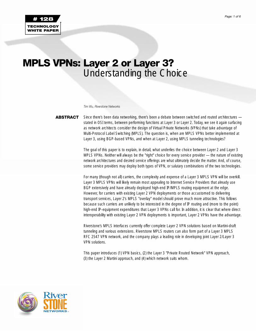
The relationship between the PE router and the Customer Edge (CE) router is the truly distinctiveaspect of 2547 VPNs. The CE router becomes a peer of the PE router (and not a peer to the otherCE routers). The CE router provides the PE router with route information for the private network. ThePE router, in turn, must be capable of storing multiple private routing tables — one for each customerconnection — along with the usual public Internet forwarding information.
ProviderEdge Router
Share IP/MPLS Network10.0.0.3
PrivateAddress
10.0.0.3PrivateAddress
10.0.0.3PrivateAddress
ProviderEdge Router
ProviderEdge Router
Site 3 Site 1
Site 2
Figure 1 — A Private BGP Network with Private IP Addresses
Page: 3 of 6# 128 TECHNOLOGY WHITE PAPER
LAYER 2 MPLS VPNS—A DIFFERENT PHILOSOPHY
MPLS handles the forwarding between the nodes on a 2547 network (in this respect, Layer 2 and 3VPN approaches are identical). This MPLS forwarding role is crucial because it means the routers inthe core of the network ("P" routers) need not know about the routes connecting the 2547 privatenetwork. A 2547 network uses a two-level label stack — the ingress PE router pushes both a Next-Hop BGP header (for the private network) and a Next-Hop Interior Gateway Protocol (IGP) header (for the shared infrastructure) onto the packet. After reaching the egress PE router via one or more MPLS Label Switched Paths (LSPs), the PE pops the MPLS headers and delivers a normal IP packet to the customer.
What is to be made of the RFC 2547 approach? It has great potential. It takes advantage of the ubiquity of IP networks and, like IP, runs over multiple transport networks. It also has strong automatic route discovery, which is important for dynamic VPNs.
On the other hand, several comparative limitations are also clear. The 2547 approach can be verydemanding of provider edge routers. Today, only the most expensive routers can maintain multiple private routing tables. While not all 2547 deployments will necessarily require anything but a numberof static routes, the potential for overburdening the network exists. Some, like AT&T’s Randy Bush,therefore believe RFC 2547 can threaten the integrity of an entire network.
A different philosophy underlies Layer 2 MPLS virtual private networks [also known as TransparentLAN Services (TLS) or Virtual Private LAN Services (VPLS)]. The goal is the extension, rather thanreplacement, of existing Layer 2 VPN services. Instead of building a separate, private IP network andrunning traffic across it, Layer 2 VPNs take existing Layer 2 traffic and send it through point-to-pointtunnels on the MPLS network backbone.
Both Layer 2 and Layer 3 MPLS VPNs rely on MPLS transport through the core. The principal difference lies in how PE-CE router relations are handled. In a Layer 2 MPLS VPN, the PE router is not a peer to the CE router and does not maintain separate routing tables. Rather, it simply mapsincoming Layer 2 traffic onto the appropriate point-to-point tunnel. The result is best described as an "overlay" model as opposed to the Layer 3 "peer" model.
Customer A
Private RouteInformation
ProviderCore Router
ProviderEdge Router
LSP
Customer B
Customer C
Customer Edge Routers
RoutingTable A
RoutingTable B
RoutingTable C
InternetRouting Table
Figure 2 — The Provider Edge/Customer Edge Router Relationship

WHICH WORKS BETTER WHERE?
Analogies are tricky, but we might think of the wide area network as a mountain that must be traversed. A 2547 VPN is more like a separate railway system that must be boarded to traverse a network of mountain tunnels. The Layer 2 approach better resembles a series of simple car tunnelsthat go straight through the mountain without the transition to rail. As this comparison suggests, there might be different reasons to want each.
Crucial to the Layer 2 VPN model is a method for establishing simple point-to-point tunnels on anMPLS network that can handle various forms of Layer 2 traffic. Today, the industry is standardizing on the Martini drafts (named after Luca Martini from Level 3 Communications), which define point-to-point encapsulation mechanisms for Ethernet, frame relay, ATM, TDM, and PPP/HDLC traffic. Indeed, Martini interoperability between many MPLS vendors was conclusively demonstrated at iLabs testing at the Networld+Interop conference in September 2001. Still other Internet drafts are building on the Martini draft encapsulations to define frame relay and ATM operation (see draftsfrom Allan, Azad, Tsenier, Koleyni, and Harrison) and to define Ethernet Transparent LAN Services (see the Lasserre draft).
The Layer 3 approach, as stated above, is ideally suited to "classic" ISP networks with existing core router deployments. It is a good fit for carriers serving large VPNs with changing locations, making automatic route discovery useful. The Layer 2 approach, on the other hand, is the preferredapproach for service providers who want to extend and scale legacy Layer 2 VPN deployments,transport-oriented carriers in general, or any situation with few VPN sites and static routes.
Many carriers may already be providing Layer 2 VPN services (over, say, frame relay or metro Ethernet)and are interested in scaling such services. In that case, the SP doesn’t want a whole new VPN infrastructure, just a way to overlay Layer 2 traffic on MPLS/IP networks. For this task, Layer 2 MPLS VPNs are ideal.
Transport-oriented carriers also should prefer the Layer 2 approach. Again, the main difference withLayer 2 VPNs is at the PE router. Among other things, the Layer 2 approach eliminates the need topeer with CE routers and maintain multiple routing tables. This approach suits carriers that traditionallyoffer transport services and leave routing to the customer. VPN traffic is carried over an IP/MPLS network, without upgrading to expensive and specialized core routers at the edge. In addition, in aLayer 2 MPLS VPN, reachability is achieved in the data plane through address learning, rather than in the control plane through BGP route exchange.
# 128 TECHNOLOGY WHITE PAPER Page: 4 of 6
Ethernet Access
LSPFrame
Access
Frame
AccessMPLS/IP Ethernet
Figure 3 — Using Layer 2 MPLS VPNs to Scale Existing Layer 2 VPNs

RIVERSTONE’SCONTRIBUTION
Finally, where routes are likely to be static and private networks simple, the relative simplicity of the Layer 2 approach is appealing. In a metro TLS scenario, for example, a carrier usually needs only to interconnect a few sites; a 2547 MPLS VPN may be overkill, from both a cost and complexity standpoint.
In the end, as MPLS VPNs are deployed, it is likely that carriers will choose Layer 2 or Layer 3 VPNsfor many of the same reasons they decided to deploy Layer 2 or Layer 3 networks. The question ofLayer 2 or Layer 3 deployment, like nature or nurture in human development, is likely to stay with networking for quite some time.
Riverstone currently offers an L2 MPLS VPN solution based on Martini code, both in point-to-pointand point-to-multi-point forms. Indeed, at the time of this writing (October 2001), the company offersthe only generally available, deployed L2 Martini VPN solution in the market. The implementation hasbeen successfully tested numerous times for interoperability with major core routers from Juniper and Cisco (most recently at the iLABS testing at N+I Atlanta, 2001). In addition, interoperability testing has shown that the Riverstone Label Switch Router can function comfortably as a P router in a 2547 network.
Riverstone has also taken an active role in developing joint Layer 2/Layer 3 MPLS VPN solutions, and has developed a migration strategy for service providers interested in supporting both Layer 2tunneling and private routed networks. Service providers interested in any aspect of Riverstone’sMPLS VPN solutions are encouraged to contact the company for further details.
# 127 TECHNOLOGY WHITE PAPER Page: 5 of 6

Page: 6 of 6
Acronyms ACL Access Control List
ANSI American National Standards Institute
ASIC Application-Specific Integrated Circuit
ASP Application Service Provider
ATM Asynchronous Transfer Mode
CBR Constant Bit Rate
CWDM Coarse Wave Division Multiplexing
DS1/DS3 Digital Signal, Level 1 (1.54 Mbps) or 3 (44.7 Mbps)
DSL Digital Subscriber Line
DWDM Dense Wave Division Multiplexing
DVMRP Distance Vector Multicast Protocol
E1/E2 European Trunk 1/2 (2 Mbps/34.3 Mbps)
ERP Enterprise Resource Planning
HSSI High Speed Serial Interface
ISP Internet Service Provider
ITU International Telecommunications Union
LAN Local Area Network
LEC Local Exchange Carrier
MAC Media Access Control
MAN Metropolitan Area Network
MDU Multiple Dwelling Unit
MLPPP Multi Layer Point-to-Point Protocol
MPLS Multiple Protocol Label Switching.
See "MPLS in Metro IP Networks,"
http://www.riverstonenet.com/technology/mpls.shtml
MTU Multiple Tenant Unit
OC-3/OC-12 Optical Carrier 3/12 (155 Mbps/622 Mbps)
PDH Plesiochronous Digital Hierarchy
PIM Protocol Independent Multicast
POS Packet over SONET
PPP Point-to-Point Protocol
PVC Private Virtual Circuit
QoS Quality of Service
RED Random Early Discard
SONET Synchronous Optical NETwork
See http://www.techguide.com/comm/sec_html/sonet.shtml
SLA Service Level Agreement
SPE Synchronous Payload Envelope
SRP Spatial Reuse Protocol
See RFC 2892
T1 Trunk 1 (1.544 Mbps)
TCP/IP Transport Control Protocol/Internet Protocol
TDM Time Division Multiplexing
UBR Undefined Bit Rate
VBR Variable Bit Rate
VLAN Virtual LAN
VoD Video on Demand
WAN Wide Area Network
WDM Wave Division Multiplexing
WRED Weighted Random Early Discard
# 128 TECHNOLOGY WHITE PAPER
Riverstone Networks, Inc.5200 Great America Parkway, Santa Clara, CA 95054 USA
877 / 778-9595 or 408 / 878-6500 or www.riverstonenet.com© 2001 Riverstone Networks, Inc. All rights reserved. Riverstone Networks, RapidOS, and Enabling Service Provider Infrastructure are trademarks or service marks of Riverstone Networks, Inc. All other trademarks mentioned herein belong to their respective owners.
Printed in the USA v 1.3 10/01
Recommended