Model W1739 Variable Speed Planer Moulder
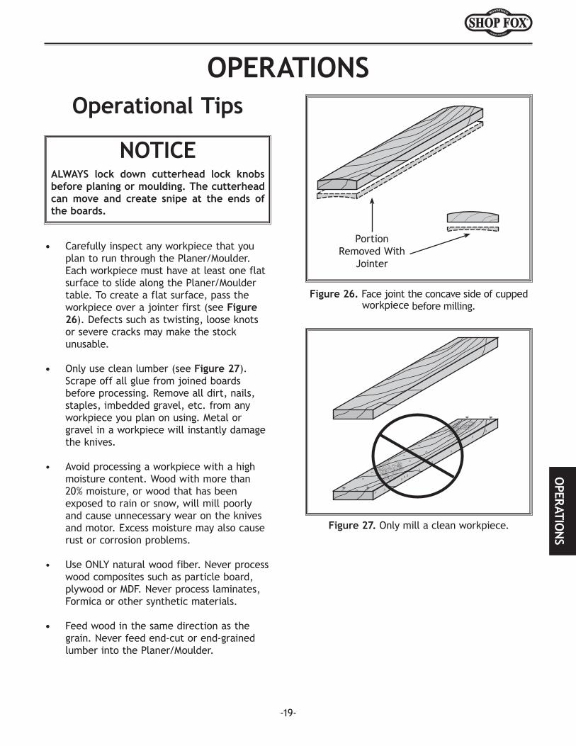
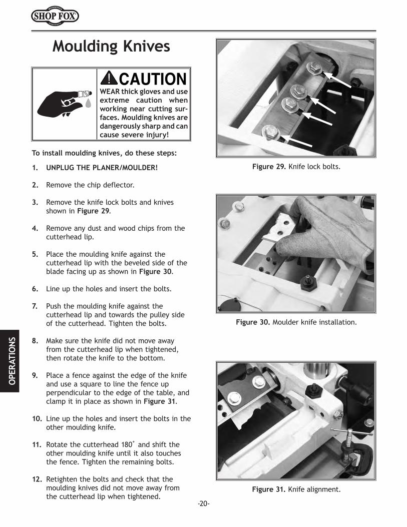
Manual Insert
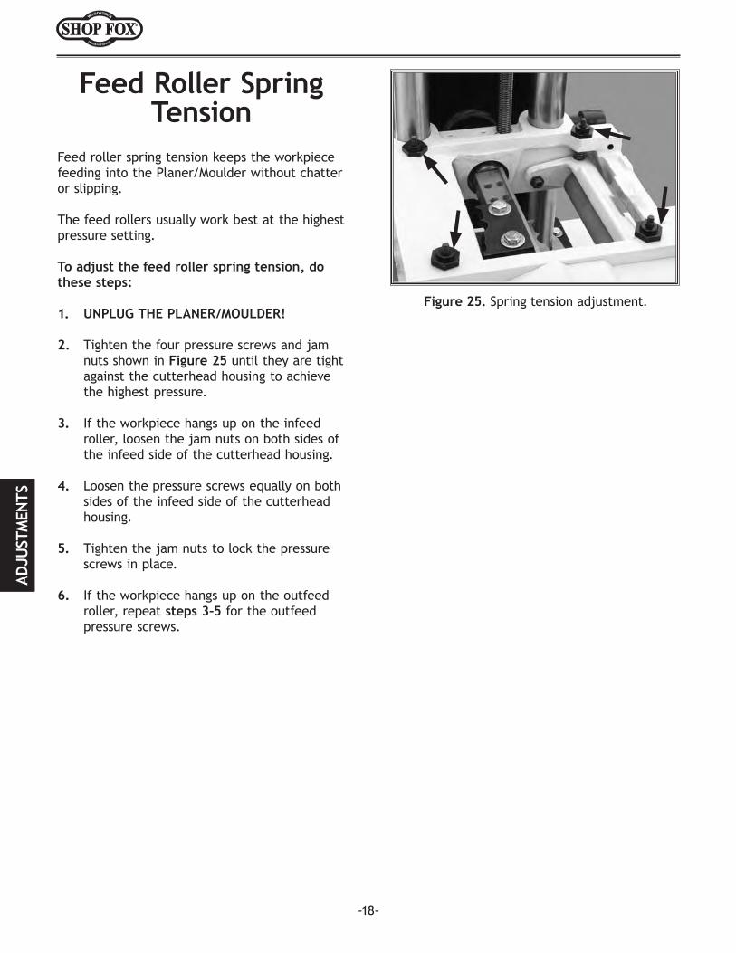
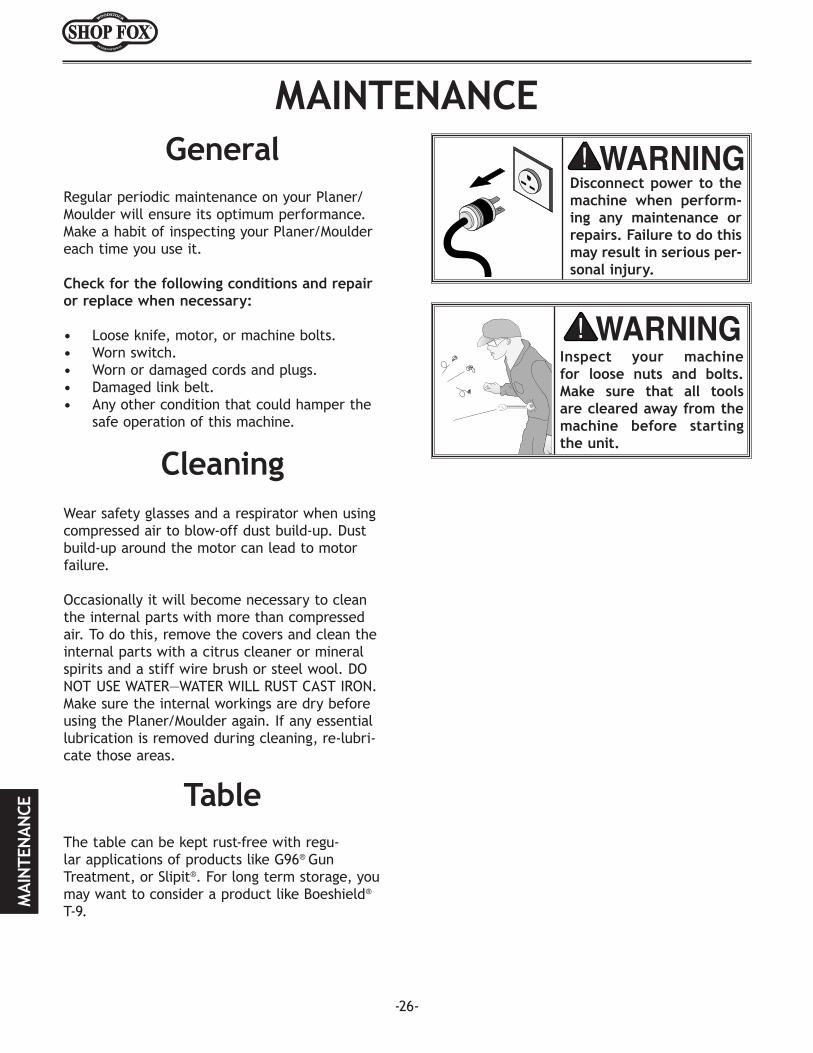
READ and understand this W1739 manual insert and the W1693 instruction manual before using this machine. Ignoring this warning may lead to serious personal injury if safety and operational information is not understood and followed.
COPYRIGHT © JANUARY, 2006 BY WOODSTOCK INTERNATIONAL, INC. REVISED FEBRUARY, 2008 (TR).WARNING: NO PORTION OF THIS MANUAL MAY BE REPRODUCED IN ANY SHAPE OR FORM WITHOUT
THE WRITTEN APPROVAL OF WOODSTOCK INTERNATIONAL, INC. Printed in Taiwan#7921CR
-2-
W1739 Variable Speed Planer/Moulder
Specifications Cutterhead Motor ................................................2 HP, 12A, 220V, Single-Phase Feed Motor ................................................................. 0.1 HP Universal Type Feed Speed .............................................................................. 4.5-18 FPM Maximum Planing Width .......................................................................... 7" Maximum Profile Width ........................................................................ 63⁄4" Maximum Profile Depth .........................................................................3⁄4" Minimum Stock Thickness .......................................................................1⁄4" Minimum Stock Length ........................................................................... 9" Cutterhead Speed ....................................................................... 7,000 RPM Cuts Per-Minute .............................................................................. 14,000 Approximate Handwheel Rotation-to-Cutterhead Travel ......................... 360º= 3⁄32" Dust Port Size ...................................................................................... 4" Footprint and Overall Height ..............................30" Wide x 20" Deep and 50" High Approximate Machine Weight ............................................................ 240 lbs.
IntroductionThis insert is intended to be used WITH the Model W1693 Owner's Manual, NOT as a substitute for it. Before operating this planer moulder, you MUST read and understand the entire Model W1693 manual.
The Model W1739 Variable Speed Planer Moulder is identical to the Model W1693 Mini Planer Moulder with the exception that the Model W1739 has a variable speed feed motor, feed speed control dial, and a modified electrical system. The operation of this planer moulder is the same, but instead of having a fixed feed rate like the W1693, the W1739 has a variable speed dial that allows you to adjust the feed rate between 4.5-18 FPM for your unique requirements.
If you have any questions about this manual insert or the differences between the Model W1693 and the Model W1739, contact our Technical Support at (360) 734-3482 or email [email protected].
-3-
W1739 Variable Speed Planer/Moulder
A7/L1 1 3/L2 L3 / 5
T22/T1 86T34 //
5 / 63 4//1 2
B
95
96 98
RESE
T
ON
15
1218
GROUND
ARC
OFF
POWER CORD
220V
FEED MOTOR
BLACK
WHITE
BLACK
WHITE
RED
SPEED CONTROL
VARIABLE
CUTTERHEAD MOTOR
CIRCUIT BOARD
BLACK
WHITE
GREEN
RED
BLACKBLACK
WHITEG
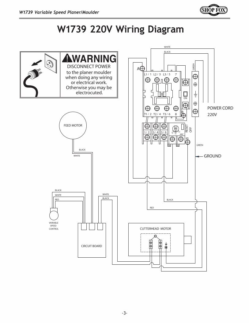
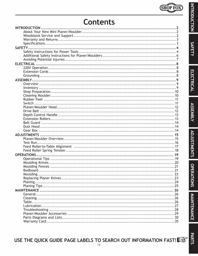
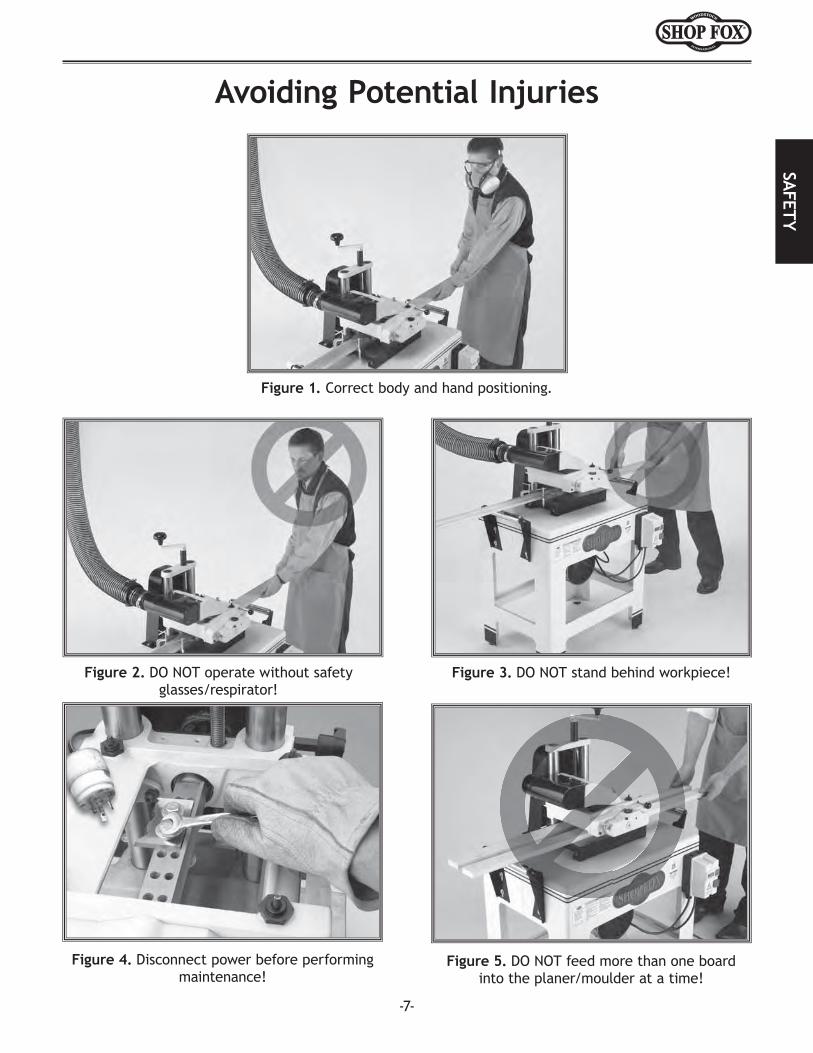
REENDISCONNECT POWER
to the planer moulder when doing any wiring
or electrical work. Otherwise you may be
electrocuted.
W1739 220V Wiring Diagram
-4-
W1739 Variable Speed Planer/Moulder
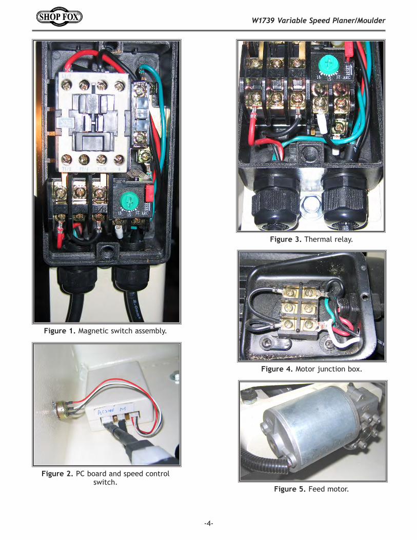
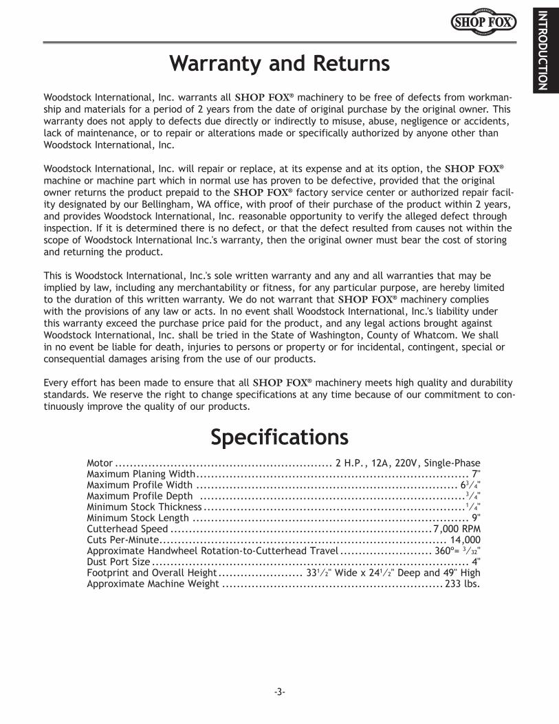
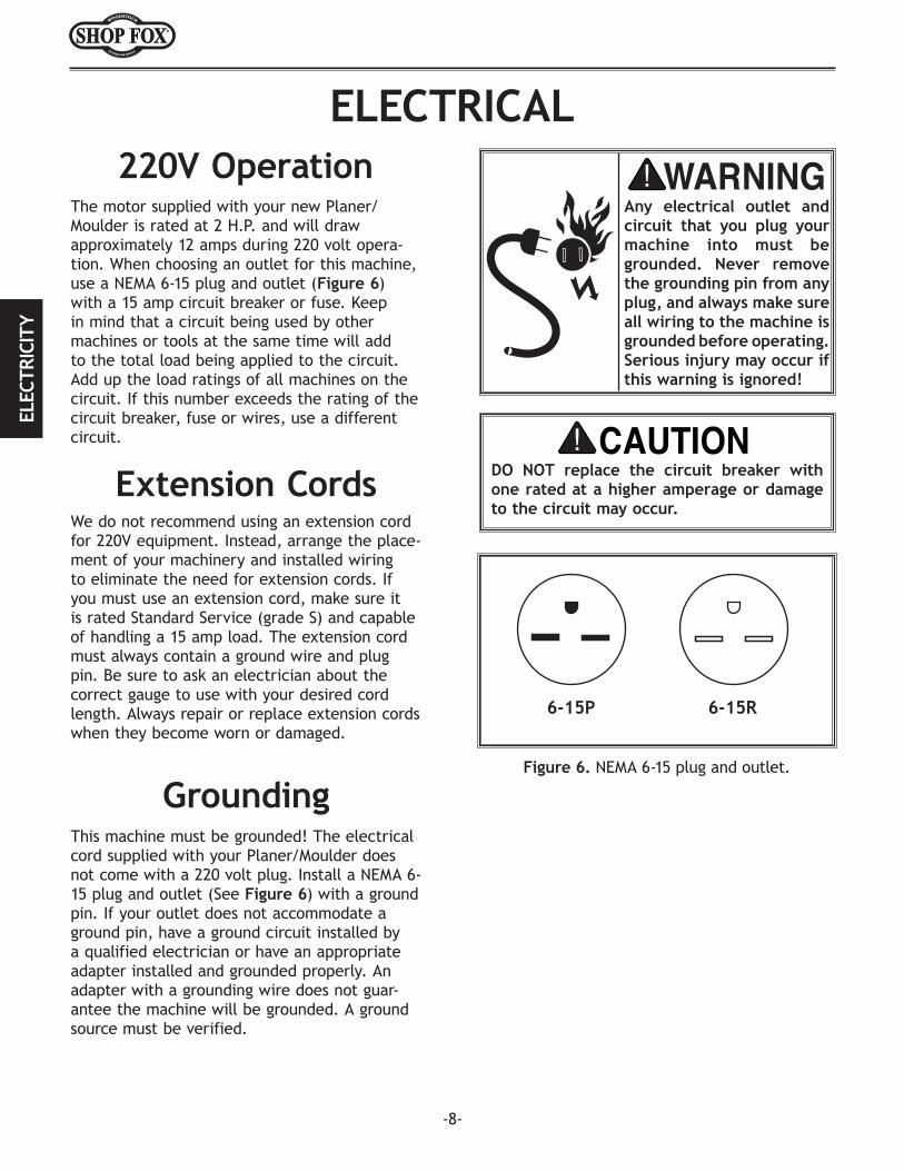
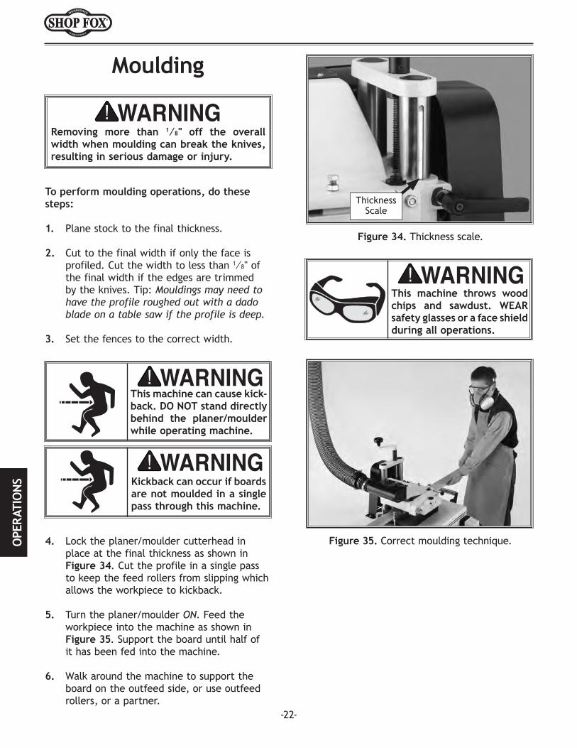
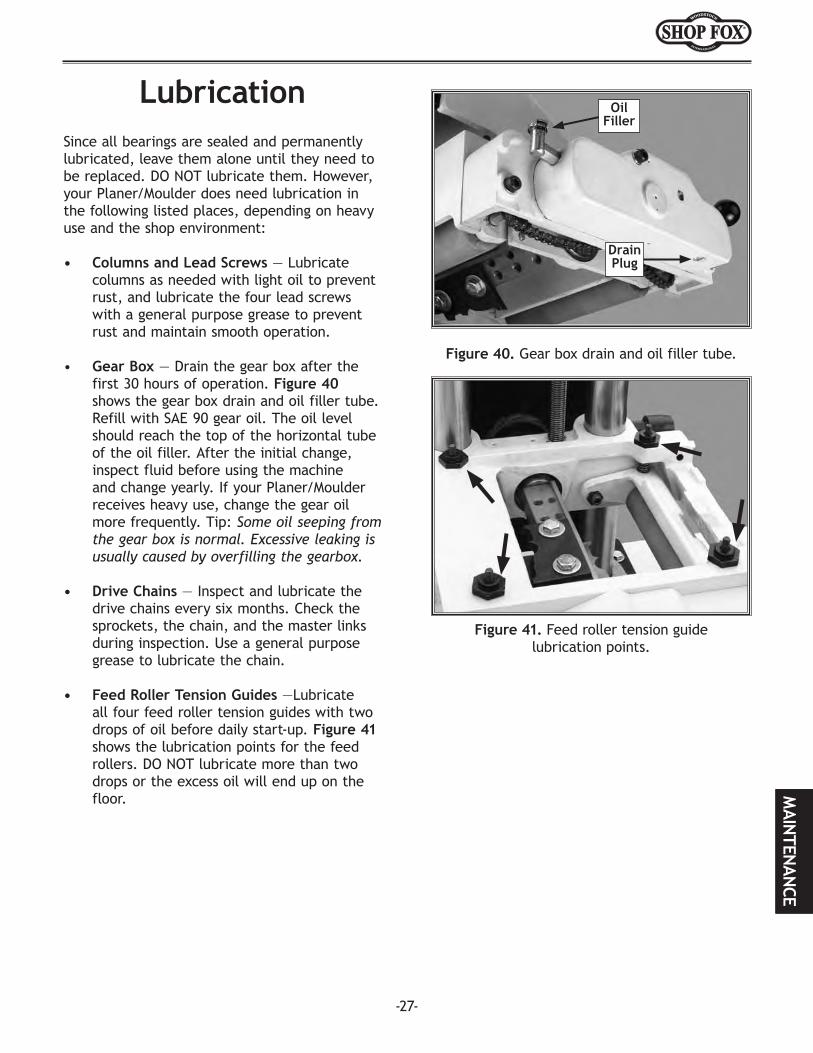
Figure 3. Thermal relay.
Figure 4. Motor junction box.
Figure 5. Feed motor.
Figure 2. PC board and speed control switch.
Figure 1. Magnetic switch assembly.
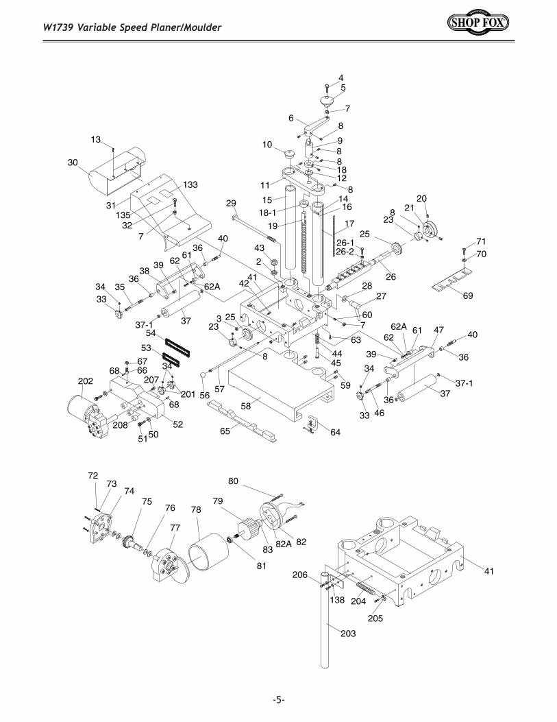
-5-
W1739 Variable Speed Planer/Moulder
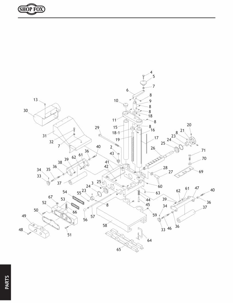
13
30
31 29
327
38
353334
37
4043
1516
11 8
6
45
7
8
14
18-1
19 17
2021
238
25
2628
27
2523
54
53
5756
58
4047
39
39
37
4633
4445
34
59
42
10
41
60
36
36
36
36
8
9
6162
6162
188
3
8
63
12
7
2
133
135
62A
62A37-1
37-1
26-126-2
69
7170
65 645150
676668 34
20168
208 52
202 207
41
203
204
206
205
138
7273
7475
76
77
78
81
79
80
8283
82A
-6-
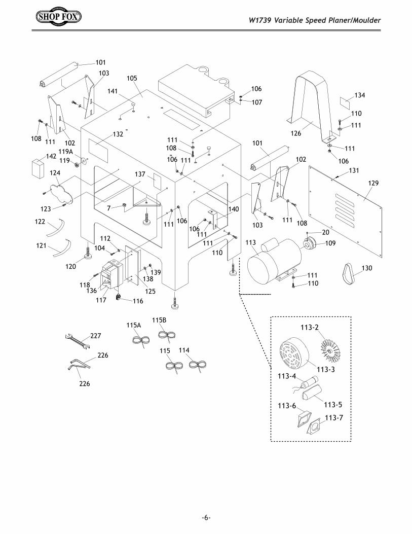
W1739 Variable Speed Planer/Moulder
101
102
103
108 111
105
106
107
101
103
102
111 108
108111
124
123 7
120
106 111
115 114
113
111110
109
20
118
117 116
106122
121
126
110
111
111
106
125
104112
129
131
130
111106
111
140
111110
141
132
137
136
134
138139
119119A
142
115A115B
113-2
113-3113-4
113-5
113-7
113-6
227
226
226
-7-
W1739 Variable Speed Planer/Moulder
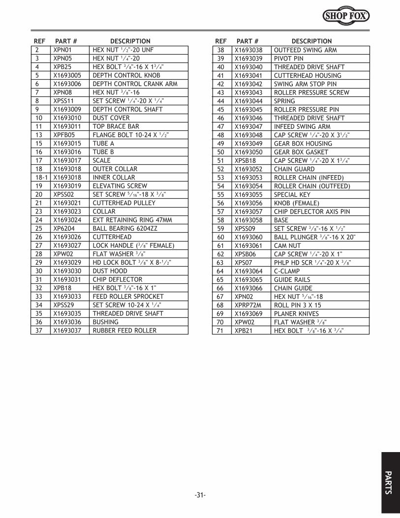
REF PART # DESCRIPTION REF PART # DESCRIPTION1 X1693001 CREAM COLOR PAINT 41 X1739041 CUTTERHEAD HOUSING2 XPN01 HEX NUT 1/2-20 42 X1693042 SWING ARM STOP PIN3 XPN05 HEX NUT 1/4-20 43 X1693043 ROLLER PRESSURE PIN4 XPB25 HEX BOLT 3/8-16 X 1-3/4 44 X1693044 COMPRESSION SPRING 1.7 X 225 X1693005 DEPTH CONTROL KNOB 45 X1693045 ROLLER PRESSURE GUIDE6 X1693006 DEPTH CONTROL CRANK ARM 46 X1693046 THREADED DRIVE SHAFT7 XPN08 HEX NUT 3/8-16 47 X1693047 INFEED SWING ARM8 XPSS11 SET SCREW 1/4-20 X 1/4 50 XPW06 FLAT WASHER 1/49 X1693009 DEPTH CONTROL SHAFT 51 XPSB40 CAP SCREW 1/4-20 X 210 X1693010 DUST COVER 52 X1739052 CHAIN GUARD11 X1693011 TOP BRACE BAR 53 X1693053 INFEED ROLLER CHAIN12 XPW14 FLAT WASHER 5/8 54 X1693054 OUTFEED ROLLER CHAIN 13 XPFB05 FLANGE BOLT 10-24 X 1/2 56 X1693056 KNOB 1/4-2014 XPRP73M ROLL PIN 4 X 30 57 X1693057 CHIP DEFLECTOR AXIS PIN15 X1693015 PLAIN TUBE A 58 X1693058 BASE16 X1693016 SLOTTED TUBE B 59 XPSS09 SET SCREW 3/8-16 X 1/217 X1693017 SCALE 60 X1693060 BALL PLUNGER 3/8-16 X 2018 X1693018 ELEVATING SCREW COLLAR 61 X1693061 CAM NUT 12 X 13.518-1 X1693018-1 ELEVATING SCREW COLLAR 62 XPSB06 CAP SCREW 1/4-20 X 119 X1693019 ELEVATING SCREW 5/8-11 X 9-1/32 63 XPS07 PHLP HD SCR 1/4-20 X 3/820 XPSS02 SET SCREW 5/16-18 X 3/8 64 X1693064 C-CLAMP21 X1693021 CUTTERHEAD PULLEY 65 X1693065 GUIDE RAILS23 X1693023 COLLAR 66 X1693066 CHAIN GUIDE25 XP6204ZNR BALL BEARING 6204 W/SNAP RING 67 XPN02 HEX NUT 5/16-1826 X1693026 CUTTERHEAD 68 XPRP72M ROLL PIN 3 X 1526-1 XPB18 HEX BOLT 3/8-16 X 1 69 X1693069 PLANER KNIVES SET OF 226-2 XPW02 FLAT WASHER 3/8 70 XPW02 FLAT WASHER 3/827 X1693027 LOCK HANDLE (3/8" FEMALE) 71 XPB21 HEX BOLT 3/8-16 X 3/428 XPW02 FLAT WASHER 3/8 72 XPS56M PHLP HD SCR M4-.7 X 1629 X1693029 HD LOCK BOLT 3/8-24 X 19/32 73 XPLW02M LOCK WASHER 4MM30 X1693030 DUST HOOD 74 X1739074 END CASE AND MAIN CASE31 X1693031 CHIP DEFLECTOR 75B X1739075B DRIVE GEAR V3.05.0732 XPB18 HEX BOLT 3/8-16 X 1 76 X1739076 THRUST WASHER33 X1693033 SHEAR SPROCKET 77 X1739074 END CASE AND MAIN CASE34 XPSS29 SET SCREW 10-24 X 1/4 78 X1739078 STATOR HOUSING35 X1693035 THREADED DRIVE SHAFT 79 X1739079 ARMATURE36 X1693036 BUSHING 80 X1739080 SHOULDER SCR M5-.8 X 9037 X1693037 RUBBER FEED ROLLER 80-1 XPLW01M LOCK WASHER 5MM37-1 XPW07 FLAT WASHER 5/16 81 XP608 BEARING 608ZZ38 X1693038 OUTFEED SWING ARM 82 X1739082 ROLLER END CAP 39 X1693039 PIVOT PIN 82A X1739082A BRUSH SET AND ISOLATOR PLATE40 X1693040 THREADED ROLLER SHAFT 83 XP608 BEARING 608ZZ
-8-
W1739 Variable Speed Planer/Moulder
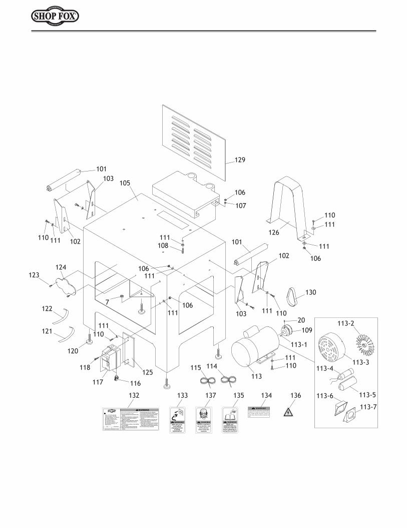
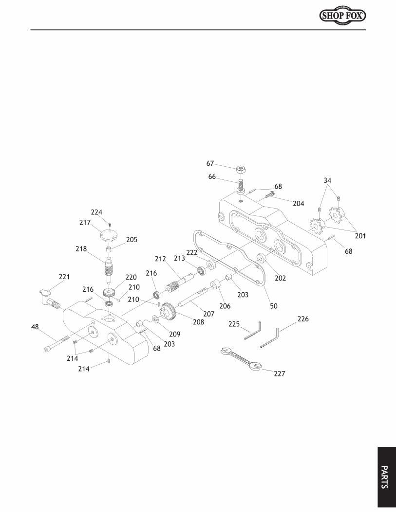
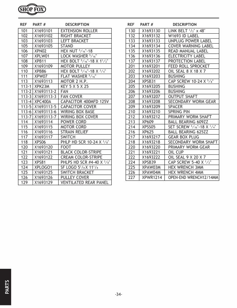
REF PART# DESCRIPTION REF PART# DESCRIPTION101 X1693101 EXTENSIONROLLER 123 XPS81 PHLPHDSCR#4-40X3/8102 X1693102 RIGHTBRACKET 124 X1693124 SHOPFOXLOGO103 X1693103 LEFTBRACKET 125 X1693125 SWITCHPLATE104 XPB32 HEXBOLT5/16-18X5/8 126 X1693126 PULLEYCOVER105 X1739105 STAND 128 XPN08 HEXNUT3/8-16106 XPN02 HEXNUT5/16-18 129 X1693129 VENTILATEDREARPANEL107 XPLW01 LOCKWASHER5/16 130 X1693130 LINKBELT1/2X48108 XPB11 HEXBOLT5/16-18X1-1/2 131 XPFB05 FLANGEBOLT10-24X1/2109 X1693109 MOTORPULLEY 132 X1739132 IDLABEL110 XPB07 HEXBOLT5/16-18X3/4 133 X1693133 UNPLUGPOWERLABEL111 XPW07 FLATWASHER5/16 134 X1693134 COVERWARNINGLABEL113 X1693113 MOTOR2HP220V1PH 135 X1693135 READMANUALLABEL113-1 XPK15M KEY5X5X35 136 X1693136 ELECTRICITYLABEL113-2 X1693113-2 FAN 137 X1693137 PROTECTIONLABEL113-3 X1693113-3 FANCOVER 138 XPW18 FLATWASHER3/16113-4 XPC400A CAPACITOR400MFD125VAC 139 XPN07 HEXNUT10-24113-5 X1693113-5 CAPACITORCOVER 140 X1693140 BRACKET113-6 X1693113-6 MOTORJUNCTIONBOXCOVER 141 X1693141 DUSTPLUG113-7 X1739113-7 MOTORJUNCTIONBOX 142 X1739142 PCBOARDCONSOLEUNIT220V114 X1693114 POWERCORD 201 X1693201 FEEDROLLERSPROCKET115 X1693115 MOTORCORD 202 X1739202 CONVEYORMOTORDC110V115-1 X1739115-1 CONTROLCORD 203 X1739203 CONDUIT115-2 X1739115-2 POWERCORD 204 X1739204 PLASTICTUBING3/8"X416"(L)116 X1693116 STRAINRELIEF 205 X1739205 CABLECLAMPS117 X1693117 MAGNETICSWITCH 206 XPFB05 FLANGEBOLT10-24X1/2118 XPS06 PHLPHDSCR10-24X5/8 207 X1739207 SPECIALSCREW1/4-20X1-1/3119 X1739119 VARIABLESPEEDCONTROLKNOB 208 X1739208 SPACER.75"ODX.62"IDX5/8"T119-1 X1739119-1 SPEEDDIALLABEL 225 XPAW03M HEXWRENCH3MM120 X1693120 FOOT 226 XPAW04M HEXWRENCH4MM121 X1693121 BLACKCOLOR-STRIPE 227 X1693227 OPEN-ENDWRENCH12/14MM122 X1693122 CREAMCOLOR-STRIPE


-12-
ASSE
MBL
YAS
SEM
BLY
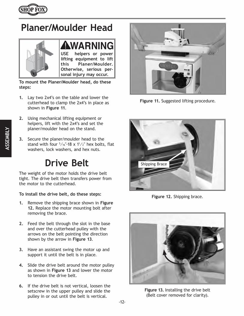
Figure 11. Suggested lifting procedure.
Figure 12. Shipping brace.
To mount the Planer/Moulder head, do these steps:
1. Lay two 2x4’s on the table and lower the cutterhead to clamp the 2x4’s in place as shown in Figure 11.
2. Using mechanical lifting equipment or helpers, lift with the 2x4’s and set the planer/moulder head on the stand.
3. Secure the planer/moulder head to the stand with four 5⁄16"-18 x 11⁄2" hex bolts, flat washers, lock washers, and hex nuts.
Drive BeltThe weight of the motor holds the drive belt tight. The drive belt then transfers power from the motor to the cutterhead.
To install the drive belt, do these steps:
1. Remove the shipping brace shown in Figure 12. Replace the motor mounting bolt after removing the brace.
2. Feed the belt through the slot in the base and over the cutterhead pulley with the arrows on the belt pointing the direction shown by the arrow in Figure 13.
3. Have an assistant swing the motor up and support it until the belt is in place.
4. Slide the drive belt around the motor pulley as shown in Figure 13 and lower the motor to tension the drive belt.
6. If the drive belt is not vertical, loosen the setscrew in the upper pulley and slide the pulley in or out until the belt is vertical.
Figure 13. Installing the drive belt(Belt cover removed for clarity).
Planer/Moulder Head
Shipping Brace
USE helpers or power lifting equipment to lift this Planer/Moulder. Otherwise, serious per-sonal injury may occur.
PARTS
Planer/Moulder AccessoriesThe following Planer/Moulder accessories may be available through your local Woodstock International Inc. Dealer. If you do not have a dealer in your area, these products are also available through online dealers. Please call or e-mail Woodstock International Inc. Customer Service to get a current listing of dealers at: 1-800-840-8420 or at [email protected].
The D2058 SHOP FOX® Super Heavy-Duty Mobile Base supports your Planer/Moulder so you can move it easily and lock it in place. Designed for long term and frequent moving of heavy machinery. All SHOP FOX® Adjustable Mobile Bases are strong enough to move heavy machines on a continual basis. The stands are adjustable to fit a vari-ety of machines and can be leveled without the use of shims or tools.
The W3393 SHOP FOX® Elliptical Jig allows you to create curved mouldings on the W1693 Planer/Moulder. With the addition of this sim-ple jig you can make mouldings for circular windows and arch topped doorways.
The SHOP FOX® Heavy-Duty Roller Stands and Roller Tables make your Planer/Moulder safer and easier to use. All models feature con-venient hand knobs for fast height adjustment and offer rigid steel construction. These stands are invaluable for supporting work on Planer/Moulders and to reduce snipe at the ends of long boards due to infeed and outfeed alignment issues.
The D2271 SHOP FOX® Heavy-Duty Roller Table is a versatile roller table wherever you need extra workpiece support for up to a 1,000 lb. capacity. It features all-steel welded construction and it measures 19" x 65" long. The roller table also comes with 9 ball bearing rollers with four independently adjustable legs for any level-ing requirement. The roller table is also adjustable in height from 263⁄8" to 441⁄8".
The W1218 Rotacator® makes a Planer/Moulder setup process easier and more accurate for adjusting the feed rollers and aligning cutterhead knives. This tool is a rotating dial indicator on a mag-netic base. Shown to the right, this handy device measures table-to-cutterhead alignment and the table roller height. The Rotacator®-
allows you to set your feed rollers to within 0.001" from being paral-lel with the table.


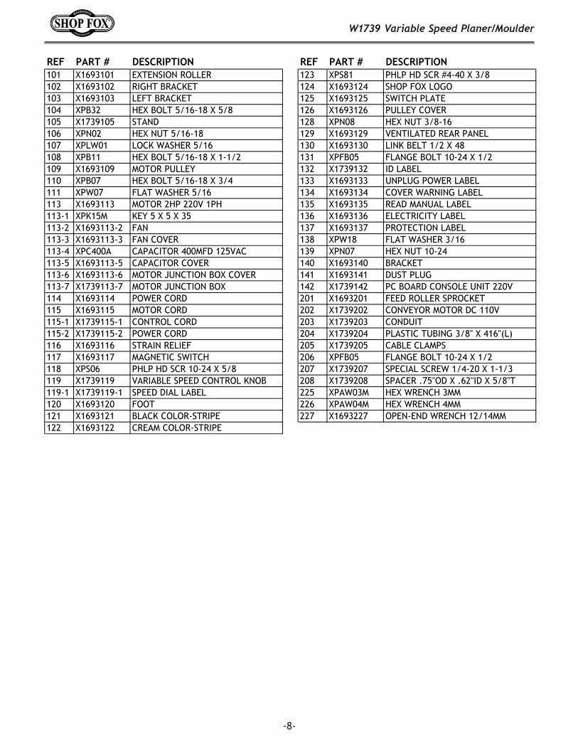
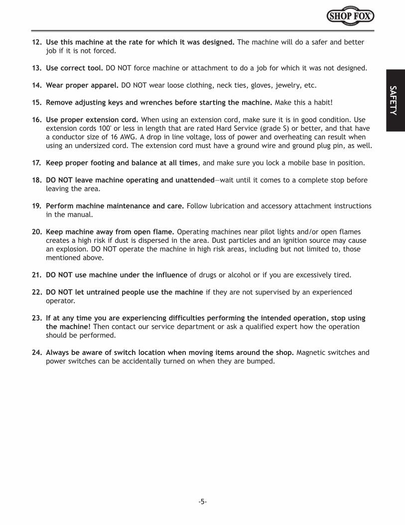
Recommended


![AAA ACCESSORIES AA · LR-10P5-1PH LR-20P5-1PH #6-32x5/16in flathead screw LR-20P5 LR-21P0-1PH LR-21P0 LR-22P0-1PH 20 LR-22P0 10 LR2-10P2-1PH 18-12 10 6/40 x 5/16 flathead 104° [40°C]](https://img.dokumen.tips/doc/110x75/5fa344e276850c162d2c86d0/aaa-accessories-aa-lr-10p5-1ph-lr-20p5-1ph-6-32x516in-flathead-screw-lr-20p5-lr-21p0-1ph.jpg)