Model FLSC-C3-XXDC Powered Microprocessor
Controlled Transmitter

-1-
CONTENTS 1. Introduction---------------------------------------------------------------- 2
2. Specifications--------------------------------------------------------------- 4
3. Installation and Operation ---------------------------------------------- 5 3.1. Power Supply--------------------------------------------------------- 5 3.2. Flowmeter Input------------------------------------------------------ 6 3.3. Pulse Output ---------------------------------------------------------- 8 3.4. Analog Output------------------------------------------------------- 10 3.5 Alarm Outputs------------------------------------------------------- 12 3.6. Communications Connections------------------------------------- 14 3.7. Wiring ---------------------------------------------------------------- 14
Appendix A – Default Configuration -------------------------------------- 15
Appendix B - Communications --------------------------------------------- 17 Message Format And Timeout------------------------------------------- 17 Messages-------------------------------------------------------------------- 19
-2-
1. Introduction
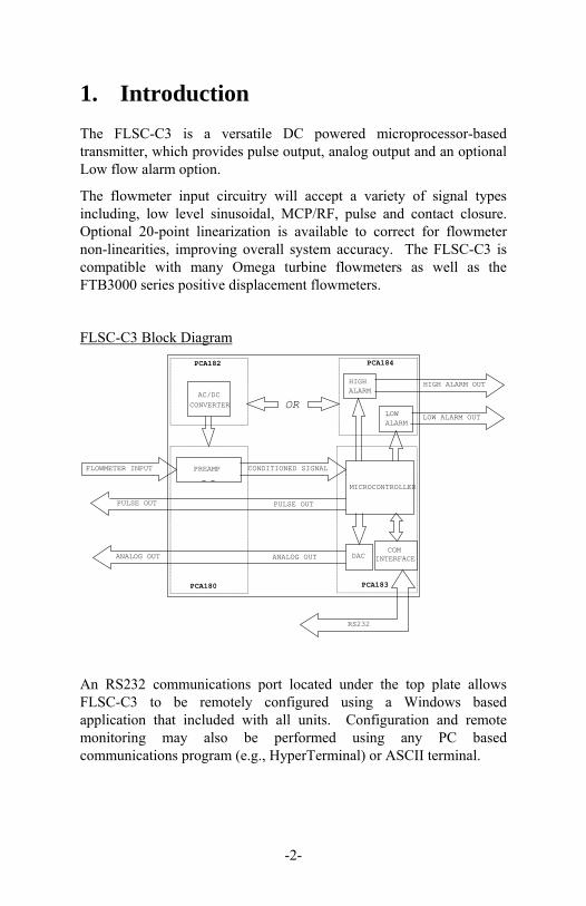
The FLSC-C3 is a versatile DC powered microprocessor-based transmitter, which provides pulse output, analog output and an optional Low flow alarm option.
The flowmeter input circuitry will accept a variety of signal types including, low level sinusoidal, MCP/RF, pulse and contact closure. Optional 20-point linearization is available to correct for flowmeter non-linearities, improving overall system accuracy. The FLSC-C3 is compatible with many Omega turbine flowmeters as well as the FTB3000 series positive displacement flowmeters.
FLSC-C3 Block Diagram
HIGH ALARM OUT
PCA180
ANALOG OUT
FLOWMETER INPUT PREAMP CONDITIONED SIGNAL
PULSE OUT
PCA182
AC/DC
OR
HIGHALARM
PCA184
LOWALARM
CONVERTER
LOW ALARM OUT
DAC
PULSE OUT
INTERFACEANALOG OUT COM
MICROCONTROLLER
RS232
PCA183
An RS232 communications port located under the top plate allows FLSC-C3 to be remotely configured using a Windows based application that included with all units. Configuration and remote monitoring may also be performed using any PC based communications program (e.g., HyperTerminal) or ASCII terminal.

-3-
The standard unit is packaged in an extruded aluminum enclosure for wall mounting or may be mounted directly on FTBG Series Turbine optional NEMA 4X or EX enclosure. An optional bracket is also available for mounting on standard DIN rail.
-4-
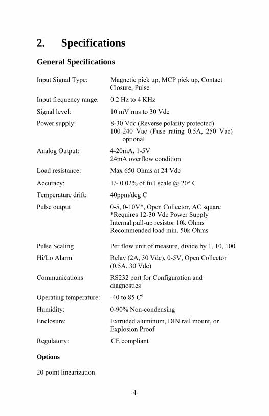
2. Specifications
General Specifications Input Signal Type: Magnetic pick up, MCP pick up, Contact Closure, Pulse
Input frequency range: 0.2 Hz to 4 KHz
Signal level: 10 mV rms to 30 Vdc
Power supply: 8-30 Vdc (Reverse polarity protected) 100-240 Vac (Fuse rating 0.5A, 250 Vac)
optional
Analog Output: 4-20mA, 1-5V 24mA overflow condition
Load resistance: Max 650 Ohms at 24 Vdc
Accuracy: +/- 0.02% of full scale @ 20 C
Temperature drift: 40ppm/deg C
Pulse output 0-5, 0-10V*, Open Collector, AC square *Requires 12-30 Vdc Power Supply Internal pull-up resistor 10k Ohms Recommended load min. 50k Ohms Pulse Scaling Per flow unit of measure, divide by 1, 10, 100
Hi/Lo Alarm Relay (2A, 30 Vdc), 0-5V, Open Collector (0.5A, 30 Vdc)
Communications RS232 port for Configuration and diagnostics
Operating temperature: -40 to 85 Co
Humidity: 0-90% Non-condensing
Enclosure: Extruded aluminum, DIN rail mount, or Explosion Proof
Regulatory: CE compliant Options 20 point linearization
-5-
3. Installation and Operation
3.1. Power Supply
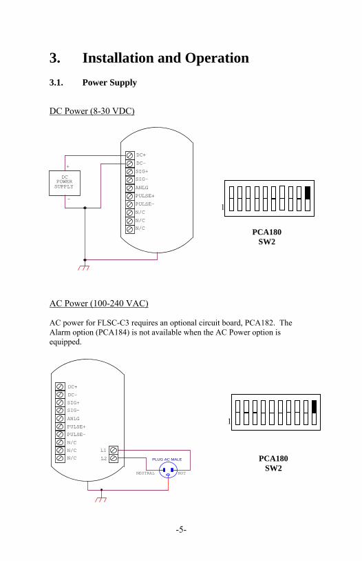
DC Power (8-30 VDC)
N/C
N/C
POWER
PULSE-
N/C
ANLGSUPPLY
SIG+DC SIG-
+
DC+
DC-
- PULSE+
AC Power (100-240 VAC) AC power for FLSC-C3 requires an optional circuit board, PCA182. The Alarm option (PCA184) is not available when the AC Power option is equipped.
DC-
DC+
SIG-
PULSE-
N/C
N/C
PULSE+
SIG+
ANLG
N/C
NEUTRAL HOT
L1
L2 PLUG AC MALE
PCA180 SW2
1
PCA180 SW2
1
-6-
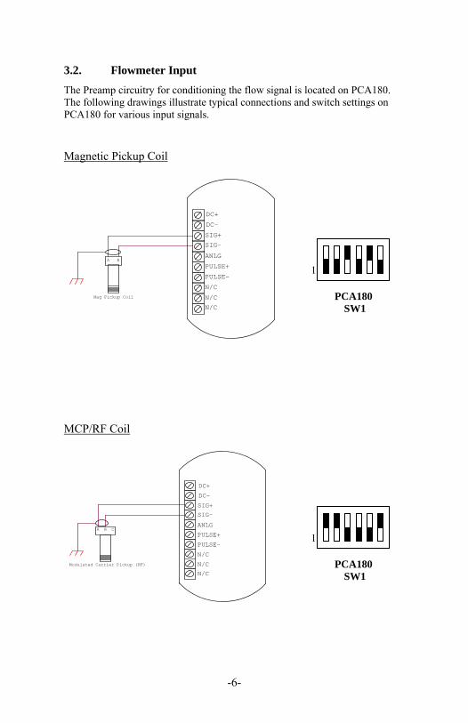
3.2. Flowmeter Input
The Preamp circuitry for conditioning the flow signal is located on PCA180. The following drawings illustrate typical connections and switch settings on PCA180 for various input signals. Magnetic Pickup Coil
A B
Mag Pickup Coil
N/C
PULSE-
N/C
N/C
SIG+
ANLG
SIG-
DC+
DC-
PULSE+
MCP/RF Coil
A B
Modulated Carrier Pickup (RF)
N/C
PULSE-
N/C
N/C
SIG+
ANLG
SIG-
DC+
DC-
PULSE+C
PCA180 SW1
1
PCA180 SW1
1
-7-
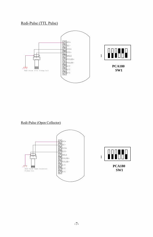
Redi-Pulse (TTL Pulse)
B A
Redi-Pulse (TTL) Pickup Coil
N/C
N/C
PULSE-
N/C
ANLG
SIG+
SIG-
DC+
DC-
PULSE+C
Redi-Pulse (Open Collector)
AB
Redi-Pulse (Open Collector)Pickup Coil
N/C
PULSE-
N/C
N/C
SIG+
ANLG
SIG-
DC+
DC-
PULSE+C
PCA180 SW1
PCA180 SW1
1
1
-8-
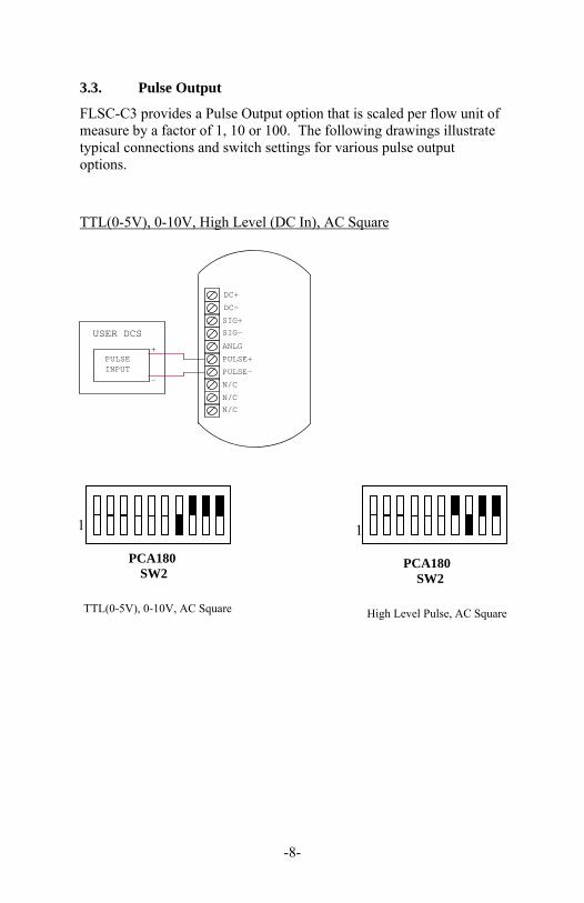
3.3. Pulse Output
FLSC-C3 provides a Pulse Output option that is scaled per flow unit of measure by a factor of 1, 10 or 100. The following drawings illustrate typical connections and switch settings for various pulse output options. TTL(0-5V), 0-10V, High Level (DC In), AC Square
PULSEINPUT
-
+
USER DCS
N/C
PULSE-
N/C
N/C
SIG+
ANLG
SIG-
DC+
DC-
PULSE+
1
PCA180
SW2
TTL(0-5V), 0-10V, AC Square
1
PCA180 SW2
High Level Pulse, AC Square
-9-
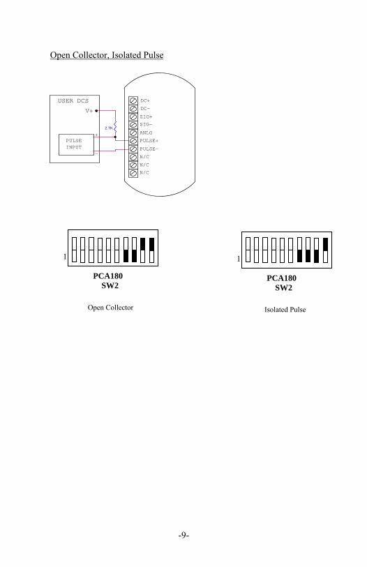
Open Collector, Isolated Pulse
PULSEINPUT
-
+
USER DCS
N/C
PULSE-
N/C
N/C
ANLG
SIG+
SIG-
DC+
DC-
PULSE+
V+
2.7K
1
PCA180 SW2
Open Collector
1
PCA180 SW2
Isolated Pulse
-10-
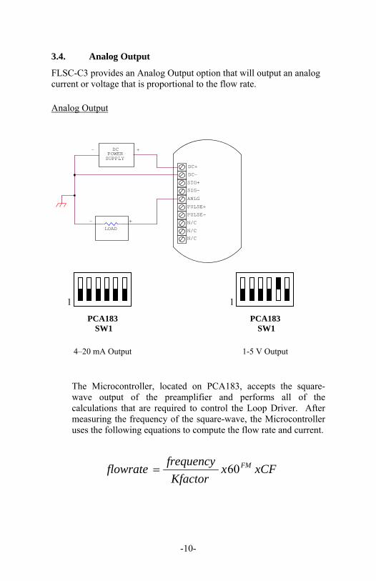
3.4. Analog Output
FLSC-C3 provides an Analog Output option that will output an analog current or voltage that is proportional to the flow rate. Analog Output
N/C
POWER
PULSE-
N/C
N/C
SUPPLY
SIG+
ANLG
DC
SIG-
+
DC+
LOAD
DC-
- +
-
PULSE+
The Microcontroller, located on PCA183, accepts the square-wave output of the preamplifier and performs all of the calculations that are required to control the Loop Driver. After measuring the frequency of the square-wave, the Microcontroller uses the following equations to compute the flow rate and current.
xCFxKfactor
frequencyflowrate FM60
PCA183 SW1
4–20 mA Output
1
PCA183 SW1
1-5 V Output
1
-11-
AF
flowratemAxmAcurrent 164
Where: Kfactor = Is dependent on the Flow Calculation Method setting and
is either the Average K-Factor or the Linearized K-Factor from the Frequency / K-Factor table.
FM = Is the Flow rate Units setting of 0, 1, or 2. Where “0” is for Seconds, “1” is for Minutes, and “2” is for Hours.
CF = Is the Correction Factor setting.
Where:
AF = Is the 20 mA maximum Flow rate value.
If the calculated flowrate is greater than the AF setting, the current will be set to 24mA to indicate an “Over-range” condition. After calculating the current, the Microcontroller digitally sends the current information to the Loop Driver. The loop driver, located on PCA183, uses the digital information sent to it by the Microcontroller to set the current of the loop. The Loop Driver also supplies power to the Microcontroller.
The analog output response time to reach steady state due to a change in the flow rate is approximately two (1/8) seconds. When flow stops, the time for the analog output to return to 4 mA will be between 3 and 12 seconds, depending on the Maximum Sample Time (MST) setting. MST is adjusted using the NB= (DATA) command, where NB is a value between 1 and 80. The default MST setting is NB= 1. Adjusting the MST is only recommended for low flow applications where the minimum input frequency is below 1 Hz.
-12-
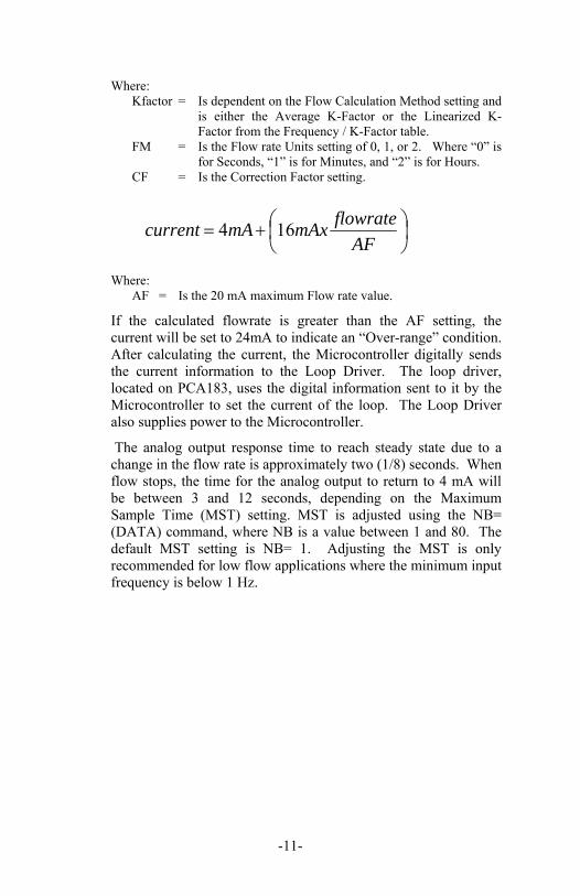
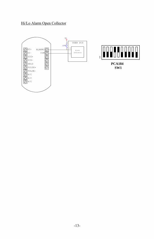
3.5. Alarm Outputs
FLSC-C3 provides an optional High/Low Flow Alarm feature. Alarms require an optional circuit board, PCA184. The Alarm option is not available on AC Power units. The drawings below illustrate the typical connections and switch settings for various alarm options. Hi/Lo Alarm Relay
SIG+
SIG-
DC+
DC-
PULSE+
NC1
COM1
NO1
High/Low-Nomally Closed
High/Low-Nomally Open
High/Low-COM
N/C
N/C
N/C
PULSE-
ANLG
Hi/Lo Alarm TTL(0-5V)
SIG+
COM
N/C
DC+
DC-
ANLG
PULSE-
PULSE+
SIG-
N/C
ALARM1
USER DCS
IndicatorAlarm
+
-
N/C
1
PCA184 SW1
1
PCA184 SW1
-13-
Hi/Lo Alarm Open Collector
USER DCS
AlarmIndicator
2.7K
V+
+
-
N/C
N/C
N/C
SIG+
ALARM1
DC-
SIG-
COM
ANLG
PULSE+
PULSE-
DC+
1
PCA184
SW1
-14-
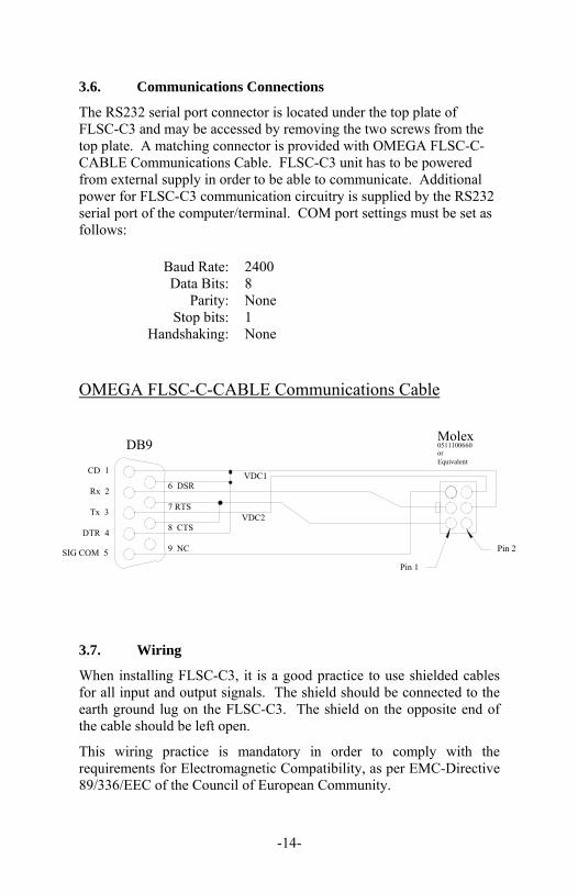
3.6. Communications Connections
The RS232 serial port connector is located under the top plate of FLSC-C3 and may be accessed by removing the two screws from the top plate. A matching connector is provided with OMEGA FLSC-C-CABLE Communications Cable. FLSC-C3 unit has to be powered from external supply in order to be able to communicate. Additional power for FLSC-C3 communication circuitry is supplied by the RS232 serial port of the computer/terminal. COM port settings must be set as follows:
Baud Rate: 2400 Data Bits: 8
Parity: None Stop bits: 1
Handshaking: None
OMEGA FLSC-C-CABLE Communications Cable
3.7. Wiring
When installing FLSC-C3, it is a good practice to use shielded cables for all input and output signals. The shield should be connected to the earth ground lug on the FLSC-C3. The shield on the opposite end of the cable should be left open.
This wiring practice is mandatory in order to comply with the requirements for Electromagnetic Compatibility, as per EMC-Directive 89/336/EEC of the Council of European Community.
Tx 3
Rx 2
DTR 4
SIG COM 5
CD 1
6 DSR
7 RTS
8 CTS
9 NC
DB9
VDC1
VDC2
Pin 2
Pin 1
Molex0511100660 orEquivalent
-15-
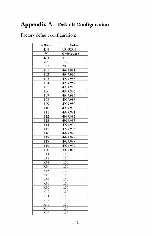
Appendix A – Default Configuration
Factory default configuration:
FIELD Value DN 10000000 FC 0 (Average) KD 3 AK 1.00 NP 20 F01 4999.981 F02 4999.982 F03 4999.983 F04 4999.984 F05 4999.985 F06 4999.986 F07 4999.987 F08 4999.988 F09 4999.989 F10 4999.990 F11 4999.991 F12 4999.992 F13 4999.993 F14 4999.994 F15 4999.995 F16 4999.996 F17 4999.997 F18 4999.998 F19 4999.999 F20 5000.000 K01 1.00 K02 1.00 K03 1.00 K04 1.00 K05 1.00 K06 1.00 K07 1.00 K08 1.00 K09 1.00 K10 1.00 K11 1.00 K12 1.00 K13 1.00 K14 1.00 K15 1.00
-16-
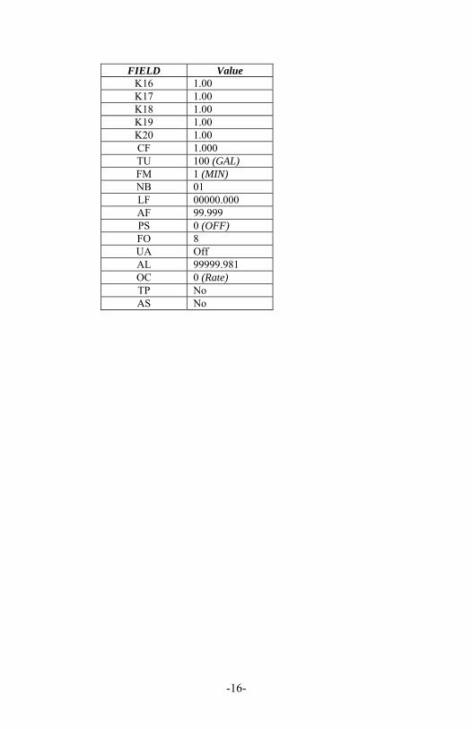
FIELD Value K16 1.00 K17 1.00 K18 1.00 K19 1.00 K20 1.00 CF 1.000 TU 100 (GAL) FM 1 (MIN) NB 01 LF 00000.000 AF 99.999 PS 0 (OFF) FO 8 UA Off AL 99999.981 OC 0 (Rate) TP No AS No
-17-
Appendix B - Communications
Message Format And Timeout
Communication messages consist of a string of ASCII characters terminated by a carriage return character. The maximum message length coming to the FLSC-C3 is 20 characters, including the carriage return. The FLSC-C3 will transmit no more than 35 characters before transmitting a carriage return.
If a message longer than 20 characters sent, the instrument responds with
“Command Sequence is Too Long!<NL>”
If an unrecognized or invalid command is sent, the instrument responds with
“Invalid Command! <NL>”
The sending unit RS232C serial port configuration must be configured as follows:
Baud rate: 2400 Data bits: 8
Parity: none Stop bits: 1
Handshaking: none The FLSC-C3 echoes all received messages and then transmits a response string terminated with a carriage return. If the sending unit takes longer than one minute to send a message, FLSC-C3 aborts the message by clearing the receive buffer.
If the sending unit (PC or other such device) wishes to change a setting on the FLSC-C3, the sending unit shall follow the command with an equal sign (“=”) with the data following immediately after the equal sign. The carriage return terminates the message.
Any FLSC-C3 response that sends data back to the sending unit shall have an equal sign (“=”) followed by the data. Space is allowed between the equal sign and the data on the return message, but the total message length is limited to 35 characters.
-18-
READ Example:
If the sending unit wishes to read the number of points that the FLSC-C3 has in the K factor table, the sending unit shall send
“NP<CR>” The FLSC-C3 echoes the sent message, and responds with
“NUM PTS = 2<CR>”
WRITE Example:
If the sending unit wishes to change the number of points to 20 in the K factor table, the sending unit shall send
“NP=20<CR>” The FLSC-C3 echoes the sent message and responds with
“NUM PTS = 20<CR>”.
The FLSC-C3 checks the ranges for data and rejects writes that are not within the allowed range. If the sending unit sends data that is not within the allowed range, the FLSC-C3 echoes the sent message and responds with the value that is currently stored in the FLSC-C3.
Example:
If the sending unit wishes to change the max sample time to 2000 from the previous setting of 10, the sending unit shall send
“NB=2000<CR>” The FLSC-C3 echoes the sent message, and responds with
“MAX M TIME= 10<CR>”.
-19-
Messages
Commands Supported By Communications Messages
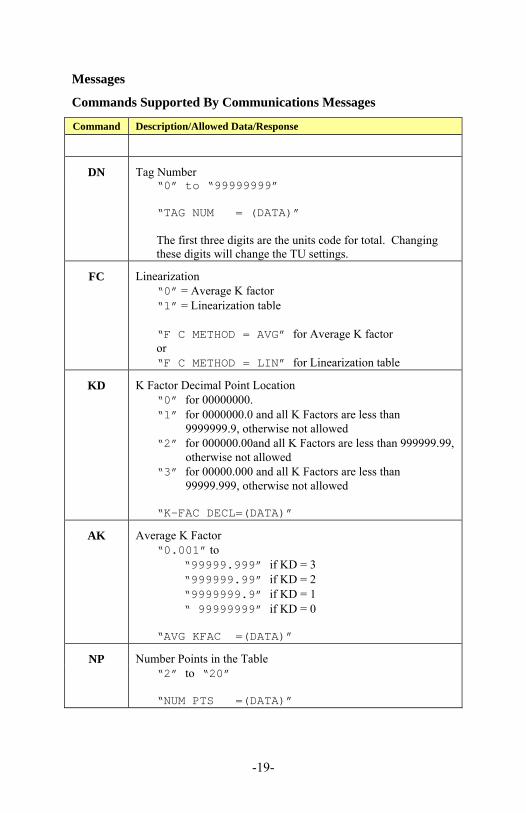
Command Description/Allowed Data/Response
DN Tag Number
“0” to “99999999” “TAG NUM = (DATA)” The first three digits are the units code for total. Changing these digits will change the TU settings.
FC Linearization
“0” = Average K factor “1” = Linearization table “F C METHOD = AVG” for Average K factor or “F C METHOD = LIN” for Linearization table
KD K Factor Decimal Point Location
“0” for 00000000. “1” for 0000000.0 and all K Factors are less than
9999999.9, otherwise not allowed “2” for 000000.00and all K Factors are less than 999999.99,
otherwise not allowed “3” for 00000.000 and all K Factors are less than
99999.999, otherwise not allowed “K-FAC DECL=(DATA)”
AK Average K Factor
“0.001” to
“99999.999” if KD = 3 “999999.99” if KD = 2 “9999999.9” if KD = 1 “ 99999999” if KD = 0
“AVG KFAC =(DATA)”
NP Number Points in the Table
“2” to “20” “NUM PTS =(DATA)”
-20-
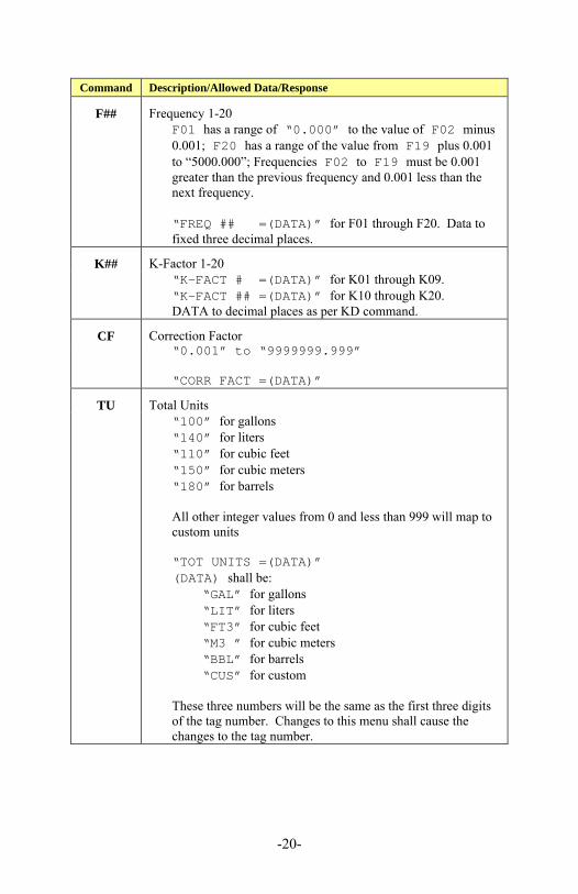
Command Description/Allowed Data/Response
F## Frequency 1-20
F01 has a range of “0.000” to the value of F02 minus 0.001; F20 has a range of the value from F19 plus 0.001 to “5000.000”; Frequencies F02 to F19 must be 0.001 greater than the previous frequency and 0.001 less than the next frequency.
“FREQ ## =(DATA)” for F01 through F20. Data to fixed three decimal places.
K## K-Factor 1-20
“K-FACT # =(DATA)” for K01 through K09. “K-FACT ## =(DATA)” for K10 through K20. DATA to decimal places as per KD command.
CF Correction Factor
“0.001” to “9999999.999” “CORR FACT =(DATA)”
TU Total Units
“100” for gallons “140” for liters “110” for cubic feet “150” for cubic meters “180” for barrels All other integer values from 0 and less than 999 will map to custom units “TOT UNITS =(DATA)” (DATA) shall be:
“GAL” for gallons “LIT” for liters “FT3” for cubic feet “M3 ” for cubic meters “BBL” for barrels “CUS” for custom
These three numbers will be the same as the first three digits of the tag number. Changes to this menu shall cause the changes to the tag number.
-21-
Command Description/Allowed Data/Response
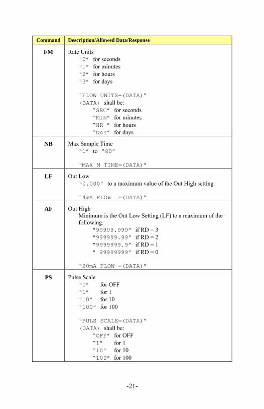
FM Rate Units
“0” for seconds “1” for minutes “2” for hours “3” for days “FLOW UNITS=(DATA)” (DATA) shall be:
“SEC” for seconds “MIN” for minutes “HR ” for hours “DAY” for days
NB Max Sample Time
“1” to “80” “MAX M TIME=(DATA)”
LF Out Low
“0.000” to a maximum value of the Out High setting “4mA FLOW =(DATA)”
AF Out High
Minimum is the Out Low Setting (LF) to a maximum of the following:
“99999.999” if RD = 3 “999999.99” if RD = 2 “9999999.9” if RD = 1 “ 99999999” if RD = 0
“20mA FLOW =(DATA)”
PS Pulse Scale
“0” for OFF “1” for 1 “10” for 10 “100” for 100 “PULS SCALE=(DATA)” (DATA) shall be:
“OFF” for OFF “1” for 1 “10” for 10 “100” for 100
-22-
Command Description/Allowed Data/Response
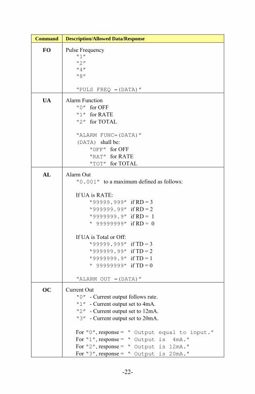
FO Pulse Frequency
“1” “2” “4” “8” “PULS FREQ =(DATA)”
UA Alarm Function
“0” for OFF “1” for RATE “2” for TOTAL “ALARM FUNC=(DATA)” (DATA) shall be:
“OFF” for OFF “RAT” for RATE “TOT” for TOTAL
AL Alarm Out
“0.001” to a maximum defined as follows: If UA is RATE:
“99999.999” if RD = 3 “999999.99” if RD = 2 “9999999.9” if RD = 1 “ 99999999” if RD = 0
If UA is Total or Off:
“99999.999” if TD = 3 “999999.99” if TD = 2 “9999999.9” if TD = 1 “ 99999999” if TD = 0
“ALARM OUT =(DATA)”
OC Current Out
“0” - Current output follows rate. “1” - Current output set to 4mA. “2” - Current output set to 12mA. “3” - Current output set to 20mA. For “0”, response = “ Output equal to input.” For “1”, response = “ Output is 4mA.” For “2”, response = “ Output is 12mA.” For “3”, response = “ Output is 20mA.”
-23-
Command Description/Allowed Data/Response
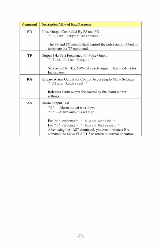
PR Pulse Output Controlled By PS and FO
“ Pulse Output Released ” The PS and FO menus shall control the pulse output. Used to terminate the TP command.
TP Output 1Hz Test Frequency for Pulse Output
“ Test Pulse Output ” Sets output to 1Hz, 50% duty cycle signal. This mode is for factory test.
RA Release Alarm Output for Control According to Menu Settings
“ Alarm Released ” Releases alarm output for control by the alarm output settings.
AS Alarm Output Test
“0” – Alarm output is set low. “1” - Alarm output is set high. For “0”, response = “ Alarm Active ” For “1”, response = “ Alarm Released ” After using the “AS” command, you must initiate a RA command to allow FLSC-C3 to return to normal operation.
-24-
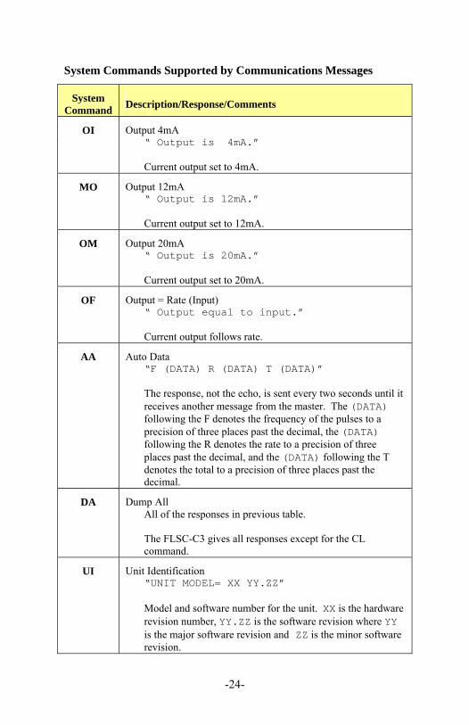
System Commands Supported by Communications Messages
System Command
Description/Response/Comments
OI Output 4mA
“ Output is 4mA.” Current output set to 4mA.
MO Output 12mA
“ Output is 12mA.” Current output set to 12mA.
OM Output 20mA
“ Output is 20mA.” Current output set to 20mA.
OF Output = Rate (Input)
“ Output equal to input.” Current output follows rate.
AA Auto Data
“F (DATA) R (DATA) T (DATA)” The response, not the echo, is sent every two seconds until it receives another message from the master. The (DATA) following the F denotes the frequency of the pulses to a precision of three places past the decimal, the (DATA) following the R denotes the rate to a precision of three places past the decimal, and the (DATA) following the T denotes the total to a precision of three places past the decimal.
DA Dump All
All of the responses in previous table. The FLSC-C3 gives all responses except for the CL command.
UI Unit Identification
“UNIT MODEL= XX YY.ZZ” Model and software number for the unit. XX is the hardware revision number, YY.ZZ is the software revision where YY is the major software revision and ZZ is the minor software revision.
-25-
System Command
Description/Response/Comments
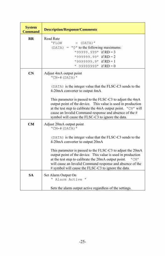
RR Read Rate
“FLOW = (DATA)” (DATA) = “0” to the following maximums:
“99999.999” if RD = 3 “999999.99” if RD = 2 “9999999.9” if RD = 1 “ 99999999” if RD = 0
CN Adjust 4mA output point
“CN=#(DATA)”
(DATA) is the integer value that the FLSC-C3 sends to the 4-20mA converter to output 4mA This parameter is passed to the FLSC-C3 to adjust the 4mA output point of the device. This value is used in production at the test step to calibrate the 4mA output point. “CN” will cause an Invalid Command response and absence of the # symbol will cause the FLSC-C3 to ignore the data.
CM Adjust 20mA output point
“CM=#(DATA)” (DATA) is the integer value that the FLSC-C3 sends to the 4-20mA converter to output 20mA This parameter is passed to the FLSC-C3 to adjust the 20mA output point of the device. This value is used in production at the test step to calibrate the 20mA output point. “CM” will cause an Invalid Command response and absence of the # symbol will cause the FLSC-C3 to ignore the data.
SA Set Alarm Output On
“ Alarm Active ” Sets the alarm output active regardless of the settings.
-26-

-27-
M-5131/0412
Recommended


![[XLS]cfs6.blog.daum.netcfs6.blog.daum.net/upload_control/download.blog?fhandle=... · Web viewJ86 J90 J92 J93 J94 J95 J96 J98 K00 K01 K02 K03 K04 K05 K06 K07 K08 K09 K10 K11 K12 K13](https://img.dokumen.tips/doc/110x75/5b3597bf7f8b9aec518d6f2c/xlscfs6blogdaum-web-viewj86-j90-j92-j93-j94-j95-j96-j98-k00-k01-k02-k03-k04.jpg)