Mastercam X8 F1 CAR BODY SW 15 to MCX8 HST Page 13-1
F1 Car
SOLIDWORKS 15 to Mastercam X82015
A. Open File in Mastercam X8.Step 1. If necessary, save your Body file in SOLIDWORKS.
Step 2. In Mastercam X8, click FILE Menu > Open.
Step 3. In the Open dialog box set Files of type toSOLIDWORKS Files, select your BODY file and click Open, Fig. 1.
Step 4. Change to Isometric View (Alt-7).
Step 5. Click Fit (Alt-F1), Fig. 2.
B. Confirm Units are Metric.Step 1. Confirm in the bottom right corner
of the display units are Metric, Fig. 2.
C. Save Your File.Step 1. Click FILE Menu
> Save As.
Step 2. Key-in BODY for the filename and press ENTER.
Chapter 3
2/20/15
Chapter 3Mastercam X8Chapter 13
Fig. 2
Fig. 1
© Cudacountry.net Tech Edhttp://www.cudacountry.net email:[email protected]
Mastercam X8 F1 CAR BODY SW 15 to MCX8 HST Page 13-2
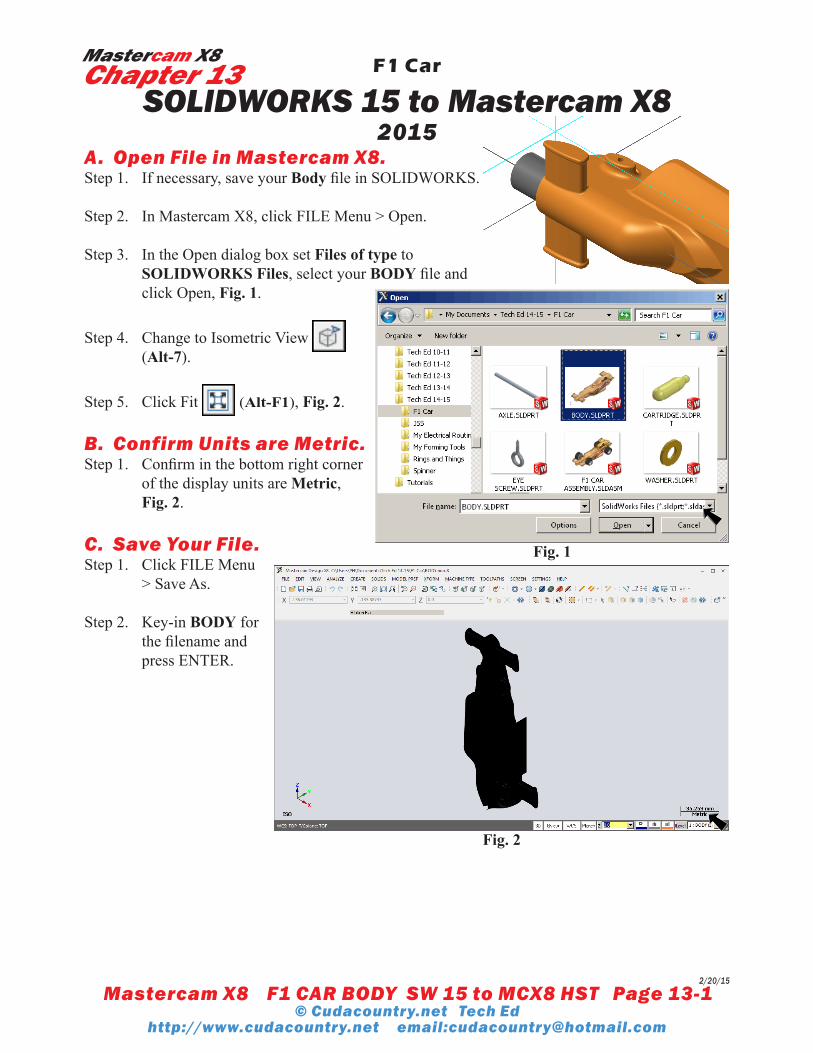
D. Delete Surfaces.Step 1. Click the Body to select, Fig. 3.
Step 2. Click Invert
in the General Selec-tion ribbon bar to select all surface imported from SOLID-WORKS Fig. 4 and Fig. 5.
Step 3. Delete all surface imported from SOLIDWORKS, Fig. 6. To delete, press Delete key.
E. Change Color.Step 1. Click the Body to select, Fig. 6.
Step 2. Right click Solid color swatch in Status Bar at bottom of graphics area, Fig. 7. Key-in 93 for orange color number and press ENTER, Fig 8.
Step 3. Save (Alt-F S).
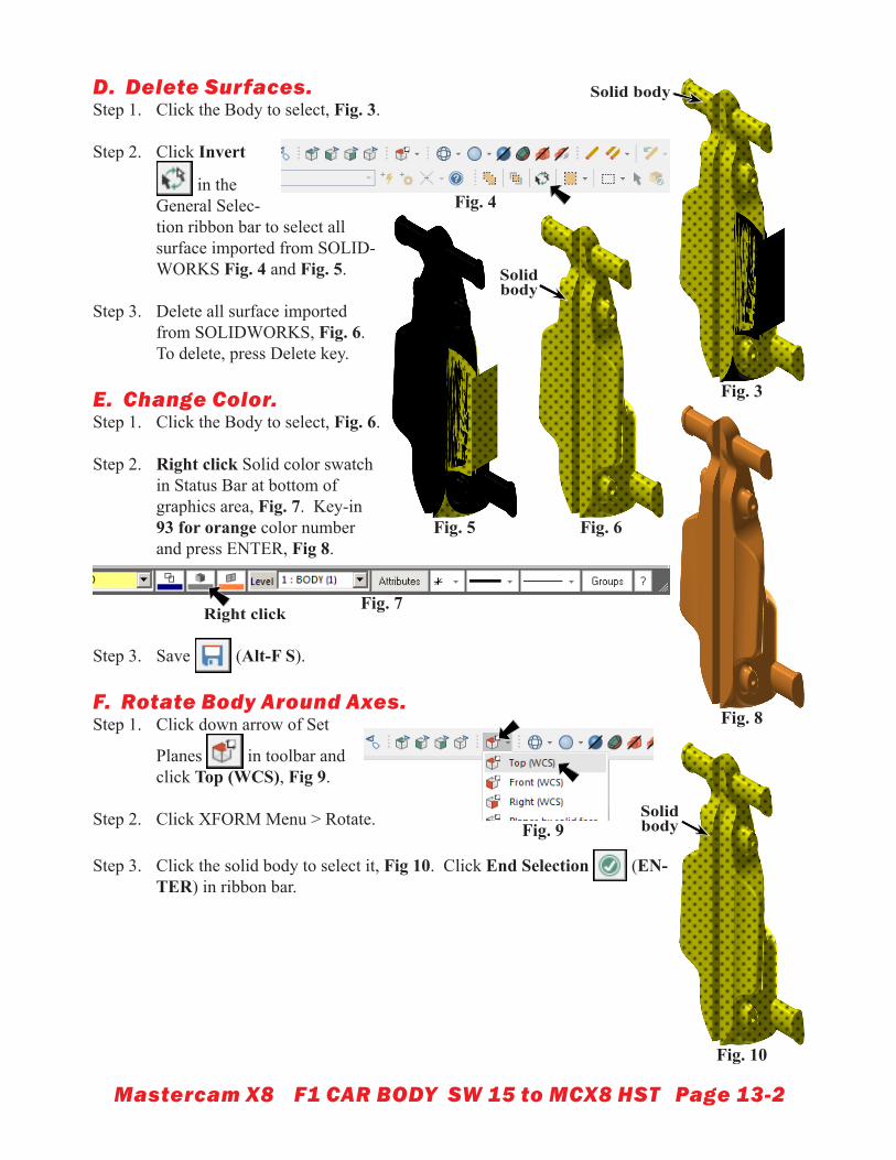
F. Rotate Body Around Axes.Step 1. Click down arrow of Set
Planes in toolbar and click Top (WCS), Fig 9.
Step 2. Click XFORM Menu > Rotate.
Step 3. Click the solid body to select it, Fig 10. Click End Selection (EN-TER) in ribbon bar.
Fig. 9
Fig. 4
Fig. 7
Fig. 3
Solid body
Fig. 6Fig. 5
Solid body
Right click
Fig. 8
Fig. 10
Solid body
Mastercam X8 F1 CAR BODY SW 15 to MCX8 HST Page 13-3
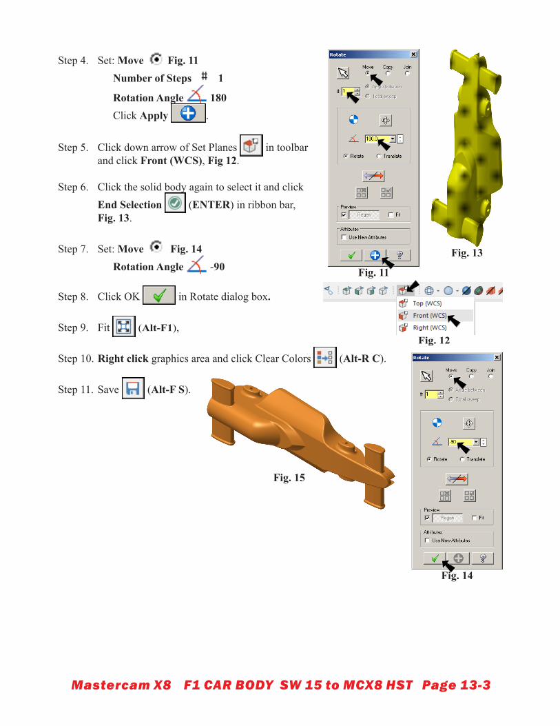
Step 4. Set: Move Fig. 11 Number of Steps 1
Rotation Angle 180 Click Apply .
Step 5. Click down arrow of Set Planes in toolbar and click Front (WCS), Fig 12.
Step 6. Click the solid body again to select it and click End Selection (ENTER) in ribbon bar,Fig. 13.
Step 7. Set: Move Fig. 14 Rotation Angle -90
Step 8. Click OK in Rotate dialog box.
Step 9. Fit (Alt-F1),
Step 10. Right click graphics area and click Clear Colors (Alt-R C).
Step 11. Save (Alt-F S).
Fig. 14
Fig. 11
Fig. 12
Fig. 13
Fig. 15
Mastercam X8 F1 CAR BODY SW 15 to MCX8 HST Page 13-4
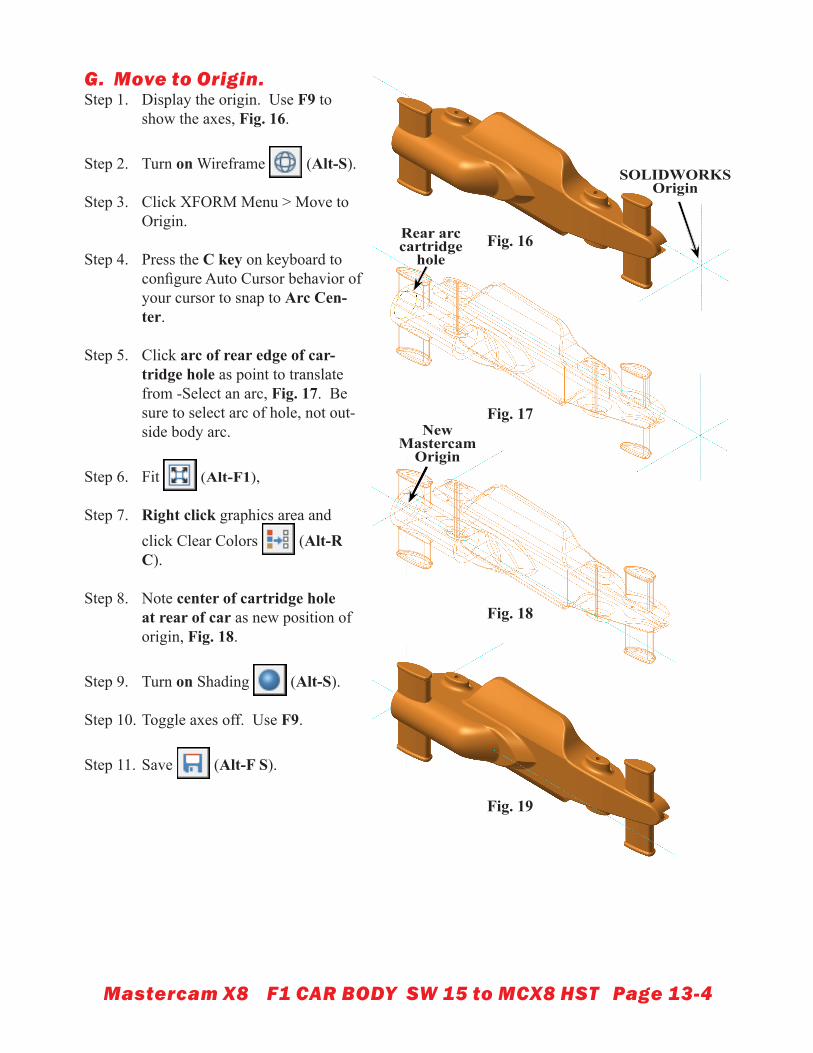
G. Move to Origin.Step 1. Display the origin. Use F9 to
show the axes, Fig. 16.
Step 2. Turn on Wireframe (Alt-S).
Step 3. Click XFORM Menu > Move to Origin.
Step 4. Press the C key on keyboard to configure Auto Cursor behavior of your cursor to snap to Arc Cen-ter.
Step 5. Click arc of rear edge of car-tridge hole as point to translate from -Select an arc, Fig. 17. Be sure to select arc of hole, not out-side body arc.
Step 6. Fit (Alt-F1),
Step 7. Right click graphics area and click Clear Colors (Alt-R C).
Step 8. Note center of cartridge hole at rear of car as new position of origin, Fig. 18.
Step 9. Turn on Shading (Alt-S).
Step 10. Toggle axes off. Use F9.
Step 11. Save (Alt-F S).
Fig. 16
SOLIDWORKS Origin
Fig. 17
Fig. 18
Fig. 19
Rear arc cartridge
hole
New Mastercam
Origin
Mastercam X8 F1 CAR BODY SW 15 to MCX8 HST Page 13-5
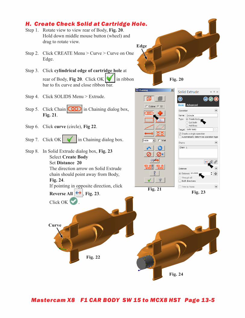
H. Create Check Solid at Cartridge Hole.Step 1. Rotate view to view rear of Body, Fig. 20.
Hold down middle mouse button (wheel) and drag to rotate view.
Step 2. Click CREATE Menu > Curve > Curve on One Edge.
Step 3. Click cylindrical edge of cartridge hole at
rear of Body, Fig 20. Click OK in ribbon bar to fix curve and close ribbon bar.
Step 4. Click SOLIDS Menu > Extrude.
Step 5. Click Chain in Chaining dialog box, Fig. 21.
Step 6. Click curve (circle), Fig 22.
Step 7. Click OK in Chaining dialog box.
Step 8. In Solid Extrude dialog box, Fig. 23 Select Create Body Set Distance 20 The direction arrow on Solid Extrude chain should point away from Body, Fig. 24. If pointing in opposite direction, click Reverse All , Fig. 23.
Click OK .
Fig. 21
Fig. 20
Edge
Fig. 23
Fig. 22
Curve
Fig. 24
Mastercam X8 F1 CAR BODY SW 15 to MCX8 HST Page 13-6
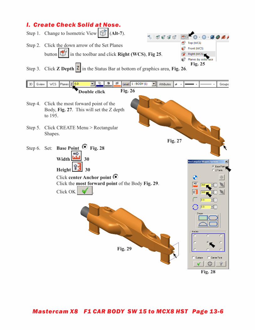
I. Create Check Solid at Nose.Step 1. Change to Isometric View (Alt-7).
Step 2. Click the down arrow of the Set Planes
button in the toolbar and click Right (WCS), Fig 25.
Step 3. Click Z Depth in the Status Bar at bottom of graphics area, Fig. 26.
Step 4. Click the most forward point of the Body, Fig. 27. This will set the Z depth to 195.
Step 5. Click CREATE Menu > Rectangular Shapes.
Step 6. Set: Base Point Fig. 28
Width 30
Height 30 Click center Anchor point Click the most forward point of the Body Fig. 29.
Click OK .
Fig. 25
Fig. 26Double click
Fig. 28
Fig. 27
Fig. 29
Mastercam X8 F1 CAR BODY SW 15 to MCX8 HST Page 13-7
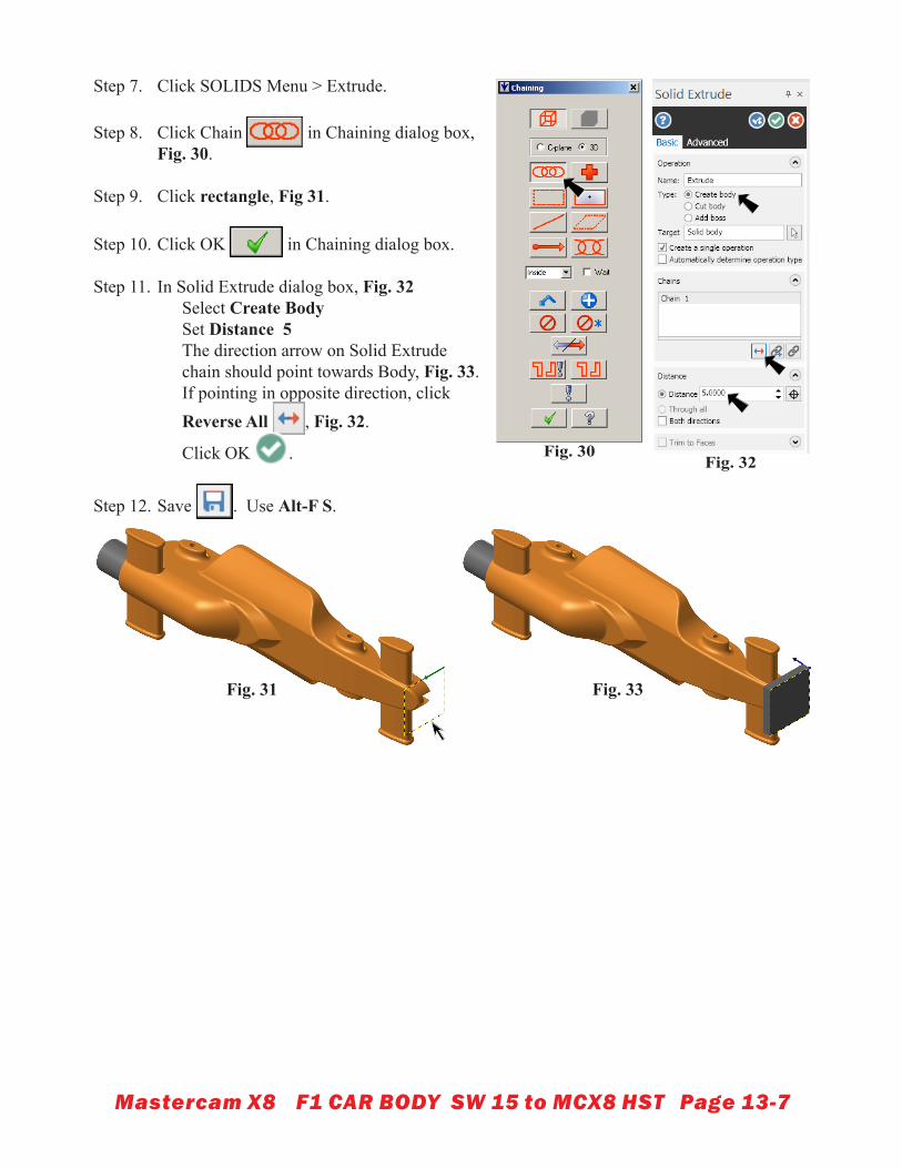
Step 7. Click SOLIDS Menu > Extrude.
Step 8. Click Chain in Chaining dialog box, Fig. 30.
Step 9. Click rectangle, Fig 31.
Step 10. Click OK in Chaining dialog box.
Step 11. In Solid Extrude dialog box, Fig. 32 Select Create Body Set Distance 5 The direction arrow on Solid Extrude chain should point towards Body, Fig. 33. If pointing in opposite direction, click Reverse All , Fig. 32.
Click OK .
Step 12. Save . Use Alt-F S.
Fig. 30Fig. 32
Fig. 31 Fig. 33
Mastercam X8 F1 CAR BODY SW 15 to MCX8 HST Page 13-8
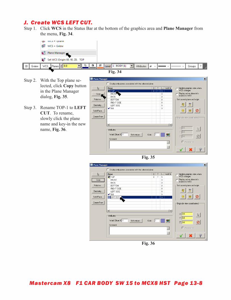
J. Create WCS LEFT CUT.Step 1. Click WCS in the Status Bar at the bottom of the graphics area and Plane Manager from
the menu, Fig. 34.
Step 2. With the Top plane se-lected, click Copy button in the Plane Manager dialog, Fig. 35.
Step 3. Rename TOP-1 to LEFT CUT. To rename, slowly click the plane name and key-in the new name, Fig. 36.
Fig. 34
Fig. 35
Fig. 36
Mastercam X8 F1 CAR BODY SW 15 to MCX8 HST Page 13-9
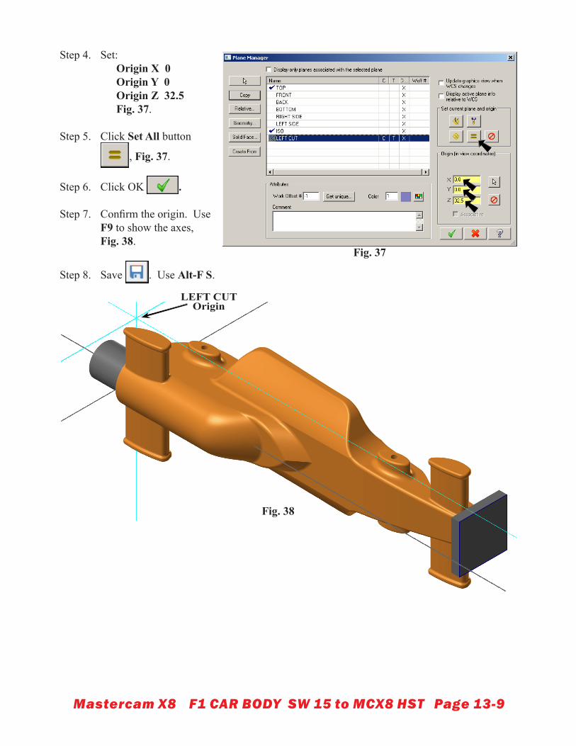
Step 4. Set: Origin X 0 Origin Y 0 Origin Z 32.5 Fig. 37.
Step 5. Click Set All button
, Fig. 37.
Step 6. Click OK .
Step 7. Confirm the origin. Use F9 to show the axes,Fig. 38.
Step 8. Save . Use Alt-F S.
Fig. 37
LEFT CUT Origin
Fig. 38
Recommended