MANUAL OF TEMPORALBONE DISSECTION
by Maurizio Barbara
Kugler Publications/The Hague/The Netherlands

I
MANUAL OF TEMPORAL BONE DISSECTION

II
III
MANUAL OF TEMPORALBONE DISSECTION
by
M. Barbara
Kugler Publications / The Hague / The Netherlands
IV
ISBN 90 6299 190 4
Distributors:For the USA and Canada:Pathway Book Service4 White Brook RoadGilsum, NH 03448 USATelefax (603) 357 2073
For all other countries:Kugler PublicationsP.O. Box 977472509 GC The Hague, The NetherlandsTelefax (+31.70) 3300254E-mail: [email protected]: kuglerpublications.com
© Copyright 2002 Kugler PublicationsAll rights reserved. No part of this book may be translated or reproduced in anyform by print, photoprint, microfilm, or any other means without prior writtenpermission of the publisher.Kugler Publications is an imprint of SPB Academic Publishing bv, P.O. Box 97747,2509 GC The Hague, The Netherlands
V
TABLE OF CONTENTS
Foreword viiPreface ixIntroduction 1Lateral (transmastoid) approach 7
Phase 1: Removal of the mastoid cortex 10Phase 2: Opening of the superficial mastoid cell system 12Phase 3: Opening of the deep mastoid cell system and
antrotomy 16Phase 4: Skeletonisation of the sigmoid sinus, opening of
the retrofacial and medial tip cells, and exposure of thejugular bulb 18
Phase 5: Posterior and anterior epitympanectomy 21Phase 6: Posterior tympanotomy (facial recess) 24Phase 7: Lowering of the posterior wall of the external
auditory canal 27Phase 8: Classical radical mastoidectomy 30Phase 9: Opening of the petrous apex 33Phase 10: Cochleostomy and cochlear visualisation 34Phase 11: Identification and skeletonisation of the
vertical intrapetrous tract of the internal carotid artery,jugular bulb (subfacial approach) and petrous apex 37
Phase 12: Facial nerve decompression (second and third portions) 39Phase 13: Identification of the endolymphatic sac 42Phase 14: Isolation of the labyrinthine block 44Phase 15: Labyrinthectomy and identification of the
intraosseous endolymphatic sac and duct 46Phase 16: Opening of the vestibule 48Phase 17: Identification of the labyrinthine segment of the
facial nerve 49Phase 18: Identification and opening of the internal auditory
canal 51Supratemporal or middle fossa approach 54
Phase 19: Opening of the epitympanic cavity and of thepetrous apex cells 56
VI
Phase 20: Identification of the facial nerve and geniculateganglion 57
Phase 21: Exposure of the internal auditory canal 59Phase 22: Isolation of the cochlea 61
Posterior cranial fossa approach 62Phase 23: Identification of the internal auditory canal 64
Abbreviations 65Glossary 67Surgical applications 69Instrumentation 70
VII
FOREWORD
The temporal bone is an anatomical jewel box of extraordinary com-plexity. Both the minuscule scale of its vital structures and their convo-luted three-dimensional relationships make microsurgery of this regionone of the most technically demanding of all operative endeavours.Unravelling the mysteries of temporal bone anatomy is the foremostchallenge faced by every otologist. The goal of achieving perfect knowl-edge and facility will never be achieved. No matter how experienced asurgeon becomes, ongoing study of the finer points of temporal boneanatomy (observed both in the operating room and dissection labora-tory) serves to maintain and improve his or her skill.
Dr Barbara has produced a highly useful Manual of Temporal BoneDissection to guide exploration of the temporal bone. Its stepwise ap-proach will prove useful for both the novice otologist and the experi-enced surgeon seeking to refresh his or her knowledge. Its orientationupon specific surgical procedures, rather than pure anatomy, enhancesits utility for the practising surgeon. This written resource is an essen-tial element of the three components needed for a high quality surgicaldissection course: a lucid manual (such as that authored by Dr Bar-bara), informative didactic sessions, and anatomical dissection proc-tored by expert microsurgeons. The team at ‘La Sapienza’ are to becongratulated for their efforts in producing an outstanding educationalprogramme.
Robert K. Jackler, MDSan Francisco
July, 2002

VIII
IX
PREFACE
When the Programme of the Permanent Educational Center in Otol-ogy at the University of Rome ‘La Sapienza’ started its First BasicCourse on the Temporal Bone in 1996, a long-standing dream of bothmy teacher, Professor Roberto Filipo, and myself was realised: to cre-ate a reference point for all colleagues who, in mid-southern Italy,wished to make a start in, or to improve their knowledge of, otologyand otosurgery.
The presence of a prestigious foreign guest of honour at each course,the use of advanced technology and, last but not least, the informal set-up of the courses expressly desired by Professor Filipo, have been thewinning weapons for the ever greater diffusion of our Center in Italy aswell as abroad.
Therefore, in the present manual, it was natural to bring together allthe teaching and advice that are offered to participants during the labo-ratory sessions, in a formula that combines pure anatomy with surgicalapplications. Although simple and certainly not exhaustive, this manualhas required a huge amount of effort, and its realisation has only beenpossible thanks to:
Professor Roberto Filipo, my teacher, for all his advice and stimulatingcriticism;Professor Robert Jackler, from the University of San Francisco (UCSF),who followed my work with his particular expertise;Mr John Ballantyne, who revised the English version of the manualwith his renowned professionalism;Drs Aleandro Harguindey, Daniele Bernardeschi and Francesco Ronchettifor their constant dedication and tirelessness;Dr Francesca Auriti for enriching the iconography;and, most of all, my beloved Simonetta for her support.
Maurizio Barbara

X
1
INTRODUCTION
This manual is for ENT specialists/residents wishing to deal with sur-gical dissection of the temporal bone, and thus to be initiated into earsurgery. However, it should only be taken as a guide and not as asubstitute for the many obligatory laboratory dissections. It is also astimulus for a deeper look at the surgical techniques in the majorotosurgical textbooks.
The major part of it will be dedicated to the lateral (transmastoid)approach – through which the huge majority of otological approachesare performed – but space will also be reserved for dissection of itssuperior (middle cranial fossa) and posterior (posterior cranial fossa)aspects. In fact, the progress in otosurgery as well as the more fre-quent cooperation with neurosurgeons, make this type of exercise veryuseful. The only difference lies in the lack of soft tissue, which isgenerally manipulated before working on the bone.
Hints !
Before starting on the topic, it is important to devote a few words tosome aspects which emerge during laboratory (or live) dissections:• the dissection should always be carried out in a well-ventilated room,
which allows for air exchange, since it will sooner or later becomesaturated with noxious agents (fixatives, bone dust, etc.);
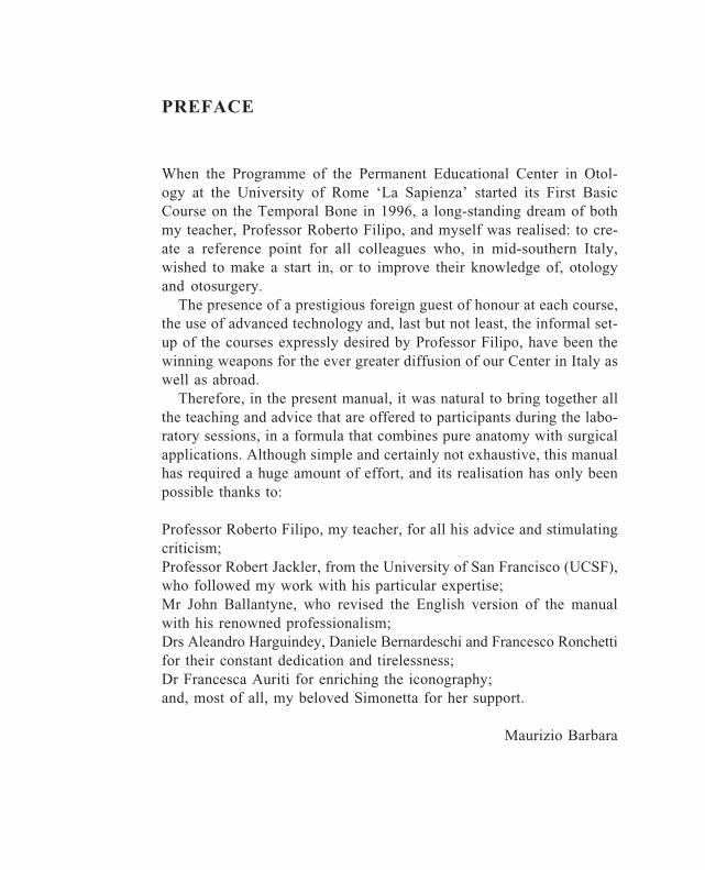
Fig. 1. A proper sitting position is advised during the dissection.
2
• protect yourself against potentially infectious materials by dressingcorrectly (waterproof gown, mask, glasses, ear plugs!);
• before starting, familiarise yourself with the laboratory instruments:operating microscope, drill, suction-irrigation system, surgical micro-instruments;
• maintain a proper sitting position, leaning against the back of thechair, with both feet (heels included) fully in contact with the floor,and both hands on a firm point (little finger, wrist) (Fig. 1-2);
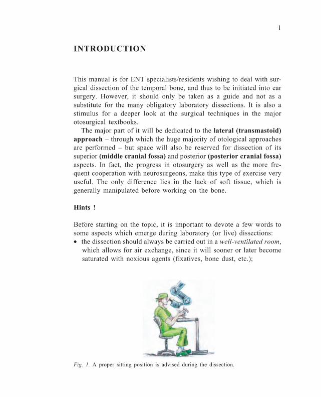
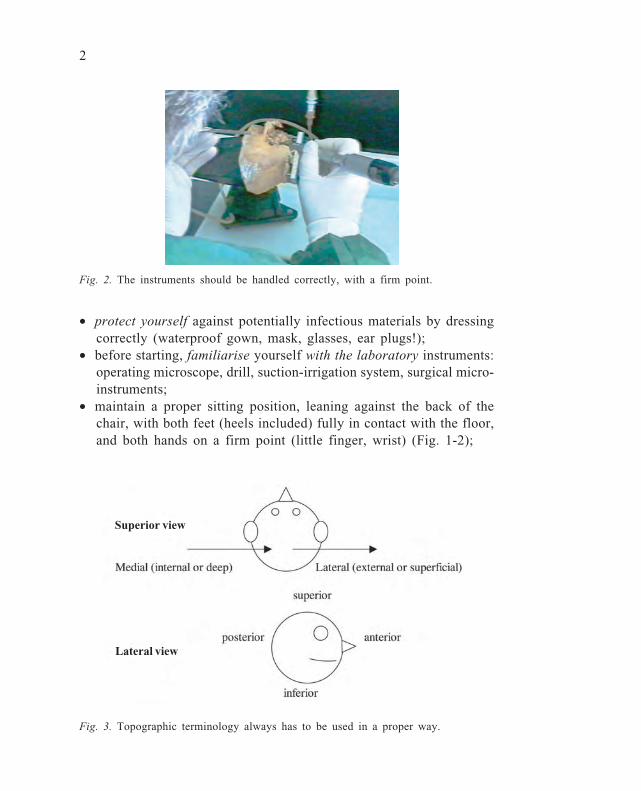
Fig. 2. The instruments should be handled correctly, with a firm point.
Fig. 3. Topographic terminology always has to be used in a proper way.
Superior view
Lateral view
3
• always follow the same steps during each dissection; use the biggestburr possible in every dissection region;
• think (and talk) in millimetres regarding the size of surgical instru-ments (hooks, burrs), prostheses, and middle ear anatomical struc-tures;
• take into account the possible anatomical variations from one boneto another in different dissections;
• manoeuvre personally the drill pedal and do the same in the operatingtheatre;
• unintentional holes in specific parts of the temporal bone (dura,sinus) are possible, and should not prevent use of the specimen:this can also depend upon the poor fixation or storage of the bones.If you are responsible for bone collection, it is better to fix thebones by freezing. Remember that, in vivo, some delicate anatomi-cal structures (dura, sigmoid sinus, jugular bulb, internal carotidartery) are more resistant than expected.
• topographic terminology is of the utmost importance and must al-ways be used correctly, i.e., superior: towards the vertex; inferior:towards the feet; anterior: towards the nose; posterior: towards thenape; lateral (or external or superficial): towards the external me-atus; medial (or internal or deep): towards the brainstem (Fig. 3).
Clean the microscope (being careful with the lens), burrs, and anyother instruments used. Leave your dissection position as clean asyou found it (Fig. 4).
When using a standard operating microscope, before looking throughit, it must be checked for the motility of each arm, without overtight-ening it, since, over time, its mechanical characteristics could be al-tered. The focal lens should be 250 mm in the laboratory, but 300 or350 mm are often used in neurotology and skull-base surgery. It isobviously important to correct for visual defects and interpupillarydistance. In order to get rapidly in focus, using macro- and micro-movements, it is better first to select the highest magnification (usu-ally 40x). Once focused on an object, magnification can be reducedand the focus will be maintained or be adjustable with minimal micro-movements (Fig. 5).

4
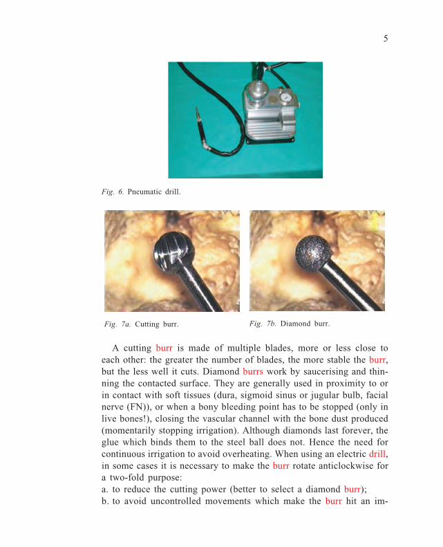
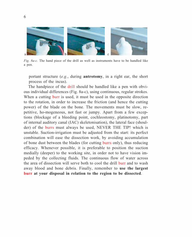
The drilling system can be threaded, electrical, or pneumatic (Fig.6). In general, only electric drills allow the burr to rotate both clock-wise and anticlockwise. You must be familiar with mounting and dis-mounting the burrs of all the systems at your disposal, since familiar-ity with the technology and instruments helps to enrich the culturalbaggage of the otologist, as well as increasing his profile in the oper-ating theatre. Two main types of burr are generally used: cutting (Fig.7a) or diamond (Fig. 7b).
Fig. 5. Operating microscope.
Fig. 4. Dissection bench.
5
A cutting burr is made of multiple blades, more or less close toeach other: the greater the number of blades, the more stable the burr,but the less well it cuts. Diamond burrs work by saucerising and thin-ning the contacted surface. They are generally used in proximity to orin contact with soft tissues (dura, sigmoid sinus or jugular bulb, facialnerve (FN)), or when a bony bleeding point has to be stopped (only inlive bones!), closing the vascular channel with the bone dust produced(momentarily stopping irrigation). Although diamonds last forever, theglue which binds them to the steel ball does not. Hence the need forcontinuous irrigation to avoid overheating. When using an electric drill,in some cases it is necessary to make the burr rotate anticlockwise fora two-fold purpose:a. to reduce the cutting power (better to select a diamond burr);b. to avoid uncontrolled movements which make the burr hit an im-
Fig. 6. Pneumatic drill.
Fig. 7a. Cutting burr. Fig. 7b. Diamond burr.
6
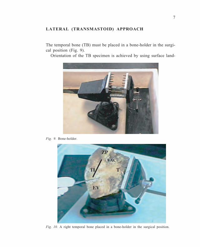
portant structure (e.g., during antrotomy, in a right ear, the shortprocess of the incus).The handpiece of the drill should be handled like a pen with obvi-
ous individual differences (Fig. 8a-c), using continuous, regular strokes.When a cutting burr is used, it must be used in the opposite directionto the rotation, in order to increase the friction (and hence the cuttingpower) of the blade on the bone. The movements must be slow, re-petitive, ho-mogeneous, not fast or jumpy. Apart from a few excep-tions (blockage of a bleeding point, cochleostomy, platinotomy, partof internal auditory canal (IAC) skeletonisation), the lateral face (shoul-der) of the burrs must always be used, NEVER THE TIP! which isunstable. Suction-irrigation must be adjusted from the start: its perfectcombination will ease the dissection work, by avoiding accumulationof bone dust between the blades (for cutting burrs only), thus reducingefficacy. Whenever possible, it is preferable to position the suctionmedially (deeper) to the working site, in order not to have vision im-peded by the collecting fluids. The continuous flow of water acrossthe area of dissection will serve both to cool the drill burr and to washaway blood and bone debris. Finally, remember to use the largestburr at your disposal in relation to the region to be dissected.
Fig. 8a-c. The hand piece of the drill as well as instruments have to be handled likea pen.
7
LATERAL (TRANSMASTOID) APPROACH
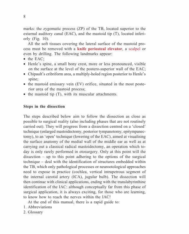
The temporal bone (TB) must be placed in a bone-holder in the surgi-cal position (Fig. 9).
Orientation of the TB specimen is achieved by using surface land-
Fig. 10. A right temporal bone placed in a bone-holder in the surgical position.
Fig. 9. Bone-holder.
8
marks: the zygomatic process (ZP) of the TB, located superior to theexternal auditory canal (EAC), and the mastoid tip (T), located inferi-orly (Fig. 10).
All the soft tissues covering the lateral surface of the mastoid pro-cess must be removed with a knife periosteal elevator, a scalpel oreven by drilling. The following landmarks appear:• the EAC;• Henle’s spine, a small bony crest, more or less pronounced, visible
on the surface at the level of the postero-superior wall of the EAC;• Chipault’s cribriform area, a multiply-holed region posterior to Henle’s
spine;• the mastoid emissary vein (EV) orifice, situated in the most poste-
rior area of the mastoid process;• the mastoid tip (T), with its muscular attachments.
Steps in the dissection
The steps described below aim to follow the dissection as close aspossible to surgical reality (also including phases that are not routinelycarried out). They will progress from a dissection centred on a ‘closed’technique (enlarged mastoidectomy, posterior tympanotomy, epitympanec-tomy), to an ‘open’ technique (lowering of the EAC), aimed at visualisingthe surface anatomy of the medial wall of the middle ear as well as atcarrying out a classical radical mastoidectomy, an operation which to-day is only rarely performed in otosurgery. Only at this point will thedissection – up to this point adhering to the options of the surgicaltechnique – deal with the identification of structures embedded withinthe TB, which only pathological processes or neurootological approachesneed to expose in practice (cochlea, vertical intrapetrous segment ofthe internal carotid artery (ICA), jugular bulb). The dissection willthen continue with clinical applications, ending with the translabyrinthineidentification of the IAC: although conceptually far from this phase ofsurgical application, it is always exciting, for those who are learning,to know how to reach the nerves within the IAC!
At the end of this manual, there is a rapid guide to:1. Abbreviations2. Glossary
9
3. Surgical applications of the dissection4. InstrumentationMoreover, in the text it is possible to find:• surgical applications in bold• cell groups in blue• microsurgical instruments in red• anatomical structures and otological nomenclature in italics
10
Phase 1: Removal of the mastoid cortex
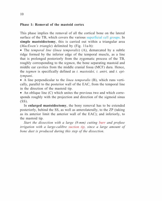
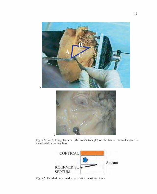
This phase implies the removal of all the cortical bone on the lateralsurface of the TB, which covers the various superficial cell groups. Insimple mastoidectomy, this is carried out within a triangular area(MacEwen’s triangle) delimited by (Fig. 11a-b):• The temporal line (linea temporalis) (A), demarcated by a subtleridge formed by the inferior edge of the temporal muscle, as a linethat is prolonged posteriorly from the zygomatic process of the TB,roughly corresponding to the tegmen, the bone separating mastoid andmiddle ear cavities from the middle cranial fossa (MCF) dura. Hence,the tegmen is specifically defined as t. mastoidei, t. antri, and t. epi-tympani.• A line perpendicular to the linea temporalis (B), which runs verti-cally, parallel to the posterior wall of the EAC, from the temporal linein the direction of the mastoid tip.• An oblique line (C) which unites the previous two and which corre-sponds roughly with the projection and direction of the sigmoid sinus(SS).
In enlarged mastoidectomy, the bony removal has to be extendedposteriorly, behind the SS, as well as anterolaterally, to the ZP (takingas its anterior limit the anterior wall of the EAC); and inferiorly, tothe mastoid tip.
Start the dissection with a large (8-mm) cutting burr and profuseirrigation with a large-calibre suction tip, since a large amount ofbone dust is produced during this step of the dissection.
11
Fig. 12. The dark area marks the cortical mastoidectomy.
Fig. 11a, b. A triangular area (McEwen’s triangle) on the lateral mastoid aspect istraced with a cutting burr.
a
b
12
Phase 2: Opening of the superficial mastoid cell system
Before starting this step, the distribution of cell groups within themastoid cavity must be remembered.
Mastoid cellsWhile in the newborn the mastoid is a single cavity (antrum) whichlies rather superficially (beware of the retroauricular incision as thefacial nerve (FN) is very superficial at this age!), after the first fewmonths and in adults, it can be pneumatic, diploic, or sclerotic, thelatter two with a few cells limited to the antrum and the central celltracts. Two main areas can be distinguished:• anterolateral (pars squamosa)• posteromedial, including the tip (pars petrosa)
These two portions are separated by the petrosquamous septum(Koerner’s), a bony lamina which is usually reabsorbed, but at timescan remain imperforate.
In order to memorise the nomenclature of the different cell groupsmore easily, without relying on personal mnemonic capabilities, sim-ply refer to the constant presence of some anatomical landmarks, suchas tegmen, SS, FN, antrum, labyrinthine block, and mastoid tip (Fig.13).
Three areas can be distinguished in the mastoid region:1. Antrum: a large space which communicates – through the aditus –
with the posterior epitympanum, and is laterally delimited by thesquamous portion;
2. Central area: extending inferior to the antrum, as a single cavity ora group of cells, partly divided by Koerner’s septum;
3. Peripheral area: including five groups of cells:a. tegmental: close to the tegmen, located superiorly;b. sinodural: occupying the posterosuperior corner of the mastoid,
superiorly limited by the tegmen, and postero-inferiorly by theSS;
c. perisinus: subdivided into lateral, medial, retrosinus (superior andinferior) and presinus;
d. perifacial;
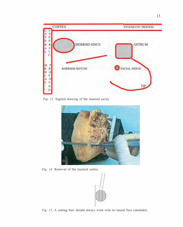
13
Fig. 13. Sagittal drawing of the mastoid cavity.
Fig. 15. A cutting burr should always work with its lateral face (shoulder).
Fig. 14. Removal of the mastoid cortex.
14
e. retrofacial: often as an isolated individual cavity, situated medi-ally and inferiorly to the vertical (mastoid) segment of the FN;
f. mastoid tip: separated by the posterior belly of the digastric muscleinto medial and lateral cells;
g. perilabyrinthine:– superior prelabyrinthine– translabyrinthine or infralabyrinthine– supralabyrinthine or petrous crest– retrolabyrinthine superior or retrolabyrinthine;
h. infralabyrinthine;i. precochlear or inferior prelabyrinthine.
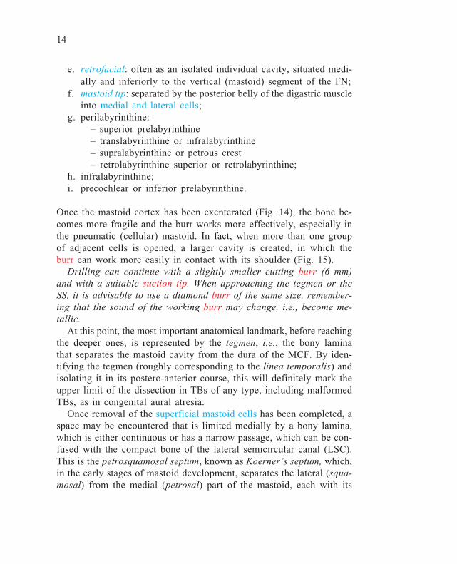
Once the mastoid cortex has been exenterated (Fig. 14), the bone be-comes more fragile and the burr works more effectively, especially inthe pneumatic (cellular) mastoid. In fact, when more than one groupof adjacent cells is opened, a larger cavity is created, in which theburr can work more easily in contact with its shoulder (Fig. 15).
Drilling can continue with a slightly smaller cutting burr (6 mm)and with a suitable suction tip. When approaching the tegmen or theSS, it is advisable to use a diamond burr of the same size, remember-ing that the sound of the working burr may change, i.e., become me-tallic.
At this point, the most important anatomical landmark, before reachingthe deeper ones, is represented by the tegmen, i.e., the bony laminathat separates the mastoid cavity from the dura of the MCF. By iden-tifying the tegmen (roughly corresponding to the linea temporalis) andisolating it in its postero-anterior course, this will definitely mark theupper limit of the dissection in TBs of any type, including malformedTBs, as in congenital aural atresia.
Once removal of the superficial mastoid cells has been completed, aspace may be encountered that is limited medially by a bony lamina,which is either continuous or has a narrow passage, which can be con-fused with the compact bone of the lateral semicircular canal (LSC).This is the petrosquamosal septum, known as Koerner’s septum, which,in the early stages of mastoid development, separates the lateral (squa-mosal) from the medial (petrosal) part of the mastoid, each with its

15
own cell groups and communicating independently with the antrum(Fig. 16).
Verification of the close anatomical relationship between antrumand LSC helps the novice to find his or her way, considering howsuperficial the dissection still is.
After finishing Phase 2, the following cell groups have been opened(Fig. 17):
superficial supra- and infra-antrallateral pre- and retrosinuslateral tegmentallateral tip
Fig. 17. Cortical and lateral mastoid cells have been exenterated.
Fig. 16. An incompletely reabsorbed Koerner’s septum (KS).
Lateral cells
16
Phase 3: Opening of the deep mastoid cell system andantrotomy
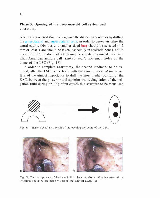
After having opened Koerner’s septum, the dissection continues by drillingthe anterolateral and superolateral cells, in order to better visualise theantral cavity. Obviously, a smaller-sized burr should be selected (4-5mm or less). Care should be taken, especially in sclerotic bones, not toopen the LSC, the dome of which may be violated by mistake, causingwhat American authors call ‘snake’s eyes’: two small holes on thedome of the LSC (Fig. 18).
In order to complete antrotomy, the second landmark to be ex-posed, after the LSC, is the body with the short process of the incus.It is of the utmost importance to drill the most medial portion of theEAC, between the posterior and superior walls. Stagnation of the irri-gation fluid during drilling often causes this structure to be visualised
Fig. 18. ‘Snake’s eyes’ as a result of the opening the dome of the LSC.
Fig. 19. The short process of the incus is first visualised (b) by refractive effect of theirrigation liquid, before being visible in the surgical cavity (a).
17
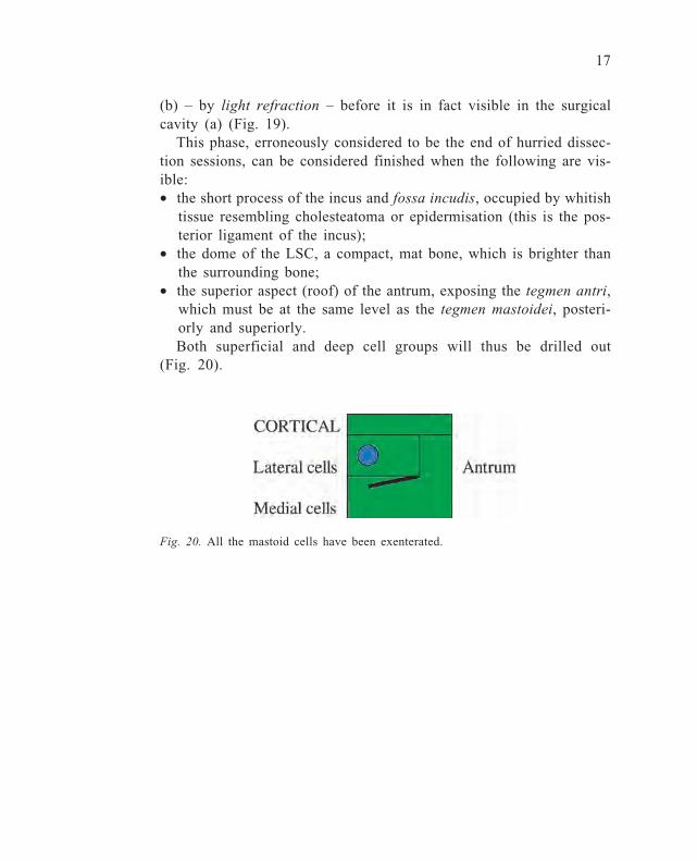
Fig. 20. All the mastoid cells have been exenterated.
(b) – by light refraction – before it is in fact visible in the surgicalcavity (a) (Fig. 19).
This phase, erroneously considered to be the end of hurried dissec-tion sessions, can be considered finished when the following are vis-ible:• the short process of the incus and fossa incudis, occupied by whitish
tissue resembling cholesteatoma or epidermisation (this is the pos-terior ligament of the incus);
• the dome of the LSC, a compact, mat bone, which is brighter thanthe surrounding bone;
• the superior aspect (roof) of the antrum, exposing the tegmen antri,which must be at the same level as the tegmen mastoidei, posteri-orly and superiorly.Both superficial and deep cell groups will thus be drilled out
(Fig. 20).
18
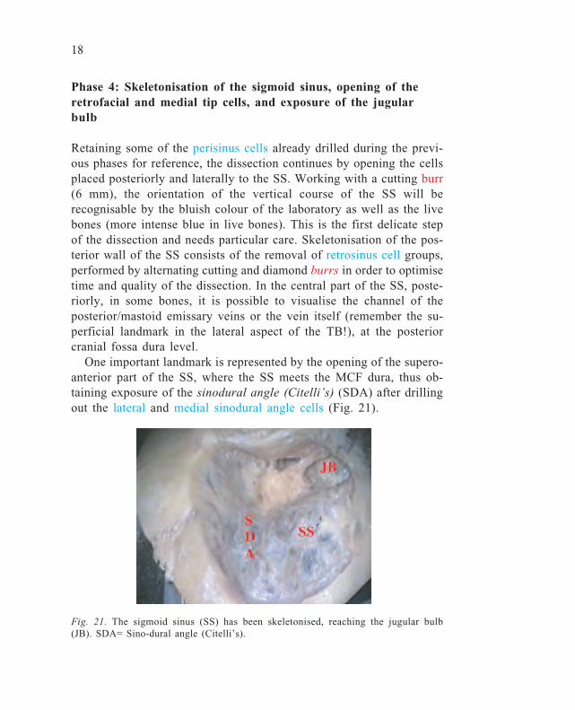
Phase 4: Skeletonisation of the sigmoid sinus, opening of theretrofacial and medial tip cells, and exposure of the jugularbulb
Retaining some of the perisinus cells already drilled during the previ-ous phases for reference, the dissection continues by opening the cellsplaced posteriorly and laterally to the SS. Working with a cutting burr(6 mm), the orientation of the vertical course of the SS will berecognisable by the bluish colour of the laboratory as well as the livebones (more intense blue in live bones). This is the first delicate stepof the dissection and needs particular care. Skeletonisation of the pos-terior wall of the SS consists of the removal of retrosinus cell groups,performed by alternating cutting and diamond burrs in order to optimisetime and quality of the dissection. In the central part of the SS, poste-riorly, in some bones, it is possible to visualise the channel of theposterior/mastoid emissary veins or the vein itself (remember the su-perficial landmark in the lateral aspect of the TB!), at the posteriorcranial fossa dura level.
One important landmark is represented by the opening of the supero-anterior part of the SS, where the SS meets the MCF dura, thus ob-taining exposure of the sinodural angle (Citelli’s) (SDA) after drillingout the lateral and medial sinodural angle cells (Fig. 21).
Fig. 21. The sigmoid sinus (SS) has been skeletonised, reaching the jugular bulb(JB). SDA= Sino-dural angle (Citelli’s).

19
Fig. 22. The insertion of the posterior belly of the digastric muscle (DM) at themastoid tip level.
Once all the lateral, medial, superior, and inferior retrosinus cellshave been opened, the dissection continues towards the mastoid tip. Atthis level, lateral and medial tip cell groups are delimited by a tangen-tial line passing through the posterior belly of the digastric muscle(DM), which forms another important landmark anteriorly in TB sur-gery: the stylomastoid foramen as the exit for the FN (third to extra-cranial parotid segment) from the TB (Fig. 22).
Careful dissection of the medial tip cells will also allow the mostinferior portion of the SS and its ascending tract towards the jugularbulb (JB), located at different heights with respect to the inferior wallof the EAC, to be isolated (Fig. 23). This step is also very delicate
Fig. 23. Isolation of the jugular bulb(JB). SS= Sigmoid sinus.
Fig. 24. The retrofacial cells (RFC) giveaccess to the jugular foramen area. CT=Chorda tympani; FN= Facial nerve.
20
since, in the majority of TBs, the venous wall is very fragile (morefragile than in live bones!), while the bony tissue around the JB isbrownish in colour (due to the bone marrow).
Only diamond burrs, of smaller and smaller calibre (from 5 to 3mm) should be used. At this point, medial and inferior to the thirdvertical segment of the FN, it is possible to visualise a group of cells,often fused in one cavity only: the retrofacial cells (RFC), which areof the utmost importance during the approach to the inferior and pos-terior walls of the tympanic cavity and, subsequently, to the petrousapex (Fig. 24).
21
Phase 5: Posterior and anterior epitympanectomy
This step, which is of extreme importance, concludes – in its initialpart limited to the posterior epitympanum – the surgical approach in aclosed (canal wall up; CWU) tympanoplasty (TPL) which, in theabsence of cholesteatoma, does not usually have to be completed witha posterior tympanotomy. It consists of progressive widening of thesuperoposterior access to the tympanic cavity already started with theantrotomy, and finishes up by visualising (remember the refractoryeffect with irrigation liquid) the short process of the incus and its in-sertion into the fossa incudis. It is very important to carry out a com-plete removal of the mastoid cortex: this will allow the antrotomy tobe widened progressively mediolaterally, i.e., passing from the morefragile to the more resistant bony parts. It must be remembered that,while at the upper and lateral levels of the dissection, it is possible toexpose the MCF dura – with a change in the sound of the burr or theonset of bleeding (another cue in live bones!) – the inferior level cor-responds to the postero-superior EAC wall, which it is preferable notto perforate. If this occurs, but the skin of the ear canal remains in-tact, no complications should be expected; if, on the other hand, theskin is missing or has been elevated as a flap, or if pathological pro-cesses such as cholesteatoma have eroded it, it is absolutely essentialto carry out a corrective osteo-(chondro)plasty. It is wise to carry outthe most delicate opening of the posterior epitympanum with small-sized diamond burrs.
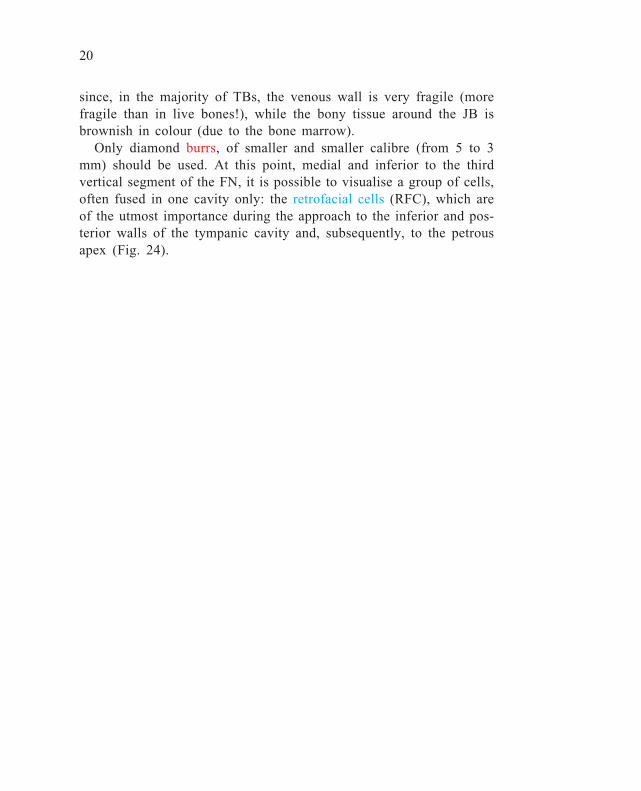
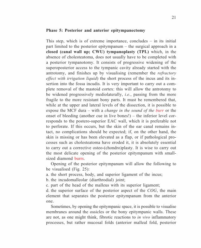
Opening of the posterior epitympanum will allow the following tobe visualised (Fig. 25):a. the short process, body, and superior ligament of the incus;b. the incudomalleolar (diarthrodial) joint;c. part of the head of the malleus with its superior ligament;d. the superior surface of the posterior aspect of the COG, the mainelement that separates the posterior epitympanum from the anteriorone.
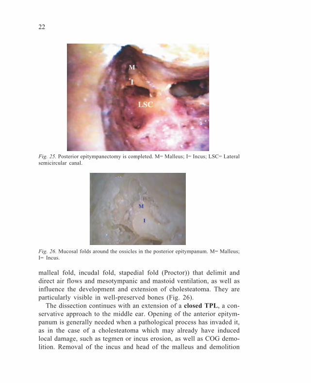
Sometimes, by opening the epitympanic space, it is possible to visualisemembranes around the ossicles or the bony epitympanic walls. Theseare not, as one might think, fibrotic reactions to in vivo inflammatoryprocesses, but rather mucosal folds (anterior malleal fold, posterior
22
Fig. 25. Posterior epitympanectomy is completed. M= Malleus; I= Incus; LSC= Lateralsemicircular canal.
Fig. 26. Mucosal folds around the ossicles in the posterior epitympanum. M= Malleus;I= Incus.
malleal fold, incudal fold, stapedial fold (Proctor)) that delimit anddirect air flows and mesotympanic and mastoid ventilation, as well asinfluence the development and extension of cholesteatoma. They areparticularly visible in well-preserved bones (Fig. 26).
The dissection continues with an extension of a closed TPL, a con-servative approach to the middle ear. Opening of the anterior epitym-panum is generally needed when a pathological process has invaded it,as in the case of a cholesteatoma which may already have inducedlocal damage, such as tegmen or incus erosion, as well as COG demo-lition. Removal of the incus and head of the malleus and demolition

23
of the COG (if still intact) by drilling, are essential steps in order togain access to the anterior epitympanum. Both ossicles are firmly an-chored, and their removal should be carried out cautiously. The incushas to be separated from the stapes head, through the posterior tympa-notomy; this manoeuvre can also be performed through the EAC afterthe creation of a tympanomeatal flap and is mandatory every time anossicular manipulation is foreseen, in order to avoid involuntary lux-ation or fracture of the stapes crura or footplate, with possible badfunctional consequences. The head of the malleus can be removed aloneby using a special instrument (malleus nipper) placed medially to themalleus neck in order to separate the head from the handle. Discon-nection of the upper ligaments of both ossicles is rather easy to per-form using small hooks. Once the posterior epitympanum has beenfreed from this part of the ossicular chain, the posterior aspect andinferior edge of the COG are visible (Fig. 27a-b).
The COG is a bony crest, generally half-moon shaped, inserted intothe tegmen with an irregular inferior concavity. Its removal must becarried out with a small (0.5-1.0 mm) diamond burr, drilling it infero-superiorly, towards the tegmen, in order not to damage the neighbouringstructures. Once the COG has been eliminated, the whole epitympa-num is opened, thus giving sight of the protympanum or supratubaricrecess, located superiorly to the tubal orifice. The close relationshipbetween the supratubaric recess, tubal orifice, and semicanal of thetensor tympani muscle should be taken into consideration.
Fig. 27a-b. After removal of the ossicles from the posterior epitympanum, COGbecomes visualised. TT: Tensor Tympani tendon.

24
Fig. 28. Thinning out the posterior canal wall (EAC) is the first step in posteriortympanotomy.
Phase 6: Posterior tympanotomy (facial recess)
Learning this step gives the otosurgeon (or, at least, the middle-earotosurgeon) his/her identity card and driving licence: when correctlyperformed, his/her effective capabilities are clearly visible, while theinability to perform it should be reason enough for stopping that par-ticular surgeon from cruising the otological highway. The aim of thisapproach is to allow visual (and instrumental) access to the tympaniccavity through the mastoidectomy cavity. Its application ranges fromclosed TPL (in which the posterior wall of the EAC remains intact) tocochlear implant surgery, FN decompression, insertion of some typesof semi-implantable hearing aids. For its proper performance, first ofall, progressive, latero-medial thinning of the posterior wall of theEAC should be carried out, until the mastoid cavity and middle earcleft are separated by only a very thin bone (Fig. 28). This thinningout must be performed by first using cutting burrs (6 mm), which –under continuous irrigation – must work homogeneously supero-infe-riorly or vice versa, using wide movements. Thinning of the posteriorEAC wall can be controlled visually – after removal of the overlyingskin – putting the suction tube in the EAC, which should be visible(by transparency) first laterally and later medially.
25
It will be appreciated that, after a simple mastoidectomy, greaterthinning of the lateral part of the posterior EAC wall has already beencarried out, while the most medial part (where the facial recess islocated) is still very thick.
With this procedure, after uniform thinning of the posterior EACwall, it will be possible to open a triangular bony space, delimitedantero-laterally by the chorda tympani (CT), posteromedially by thevertical segment of the FN, and superiorly by a bony lamina (buttress)that separates it from the fossa incudis, which supports the short pro-cess of the incus (Fig. 29a-b-c).
This fossa is always occupied by a whitish tissue (the posterior incudalligament) which can be confused with epidermisation. It is importantto bear in mind that the lateral limit of posterior tympanotomy – thechorda tympani – coincides anteriorly with the fibrous annulus and,
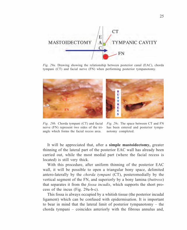
Fig. 29a. Drawing showing the relationship between posterior canal (EAC), chordatympani (CT) and facial nerve (FN) when performing posterior tympanotomy.
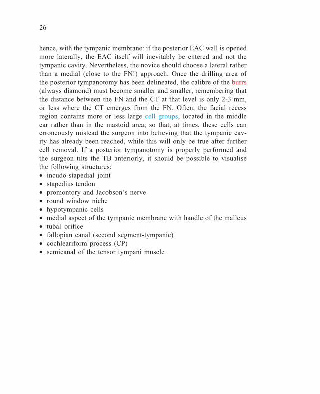
Fig. 29b. Chorda tympani (CT) and facialnerve (FN) represent two sides of the tri-angle which forms the facial recess area.
Fig. 29c. The space between CT and FNhas been entered and posterior tympa-notomy completed.
26
hence, with the tympanic membrane: if the posterior EAC wall is openedmore laterally, the EAC itself will inevitably be entered and not thetympanic cavity. Nevertheless, the novice should choose a lateral ratherthan a medial (close to the FN!) approach. Once the drilling area ofthe posterior tympanotomy has been delineated, the calibre of the burrs(always diamond) must become smaller and smaller, remembering thatthe distance between the FN and the CT at that level is only 2-3 mm,or less where the CT emerges from the FN. Often, the facial recessregion contains more or less large cell groups, located in the middleear rather than in the mastoid area; so that, at times, these cells canerroneously mislead the surgeon into believing that the tympanic cav-ity has already been reached, while this will only be true after furthercell removal. If a posterior tympanotomy is properly performed andthe surgeon tilts the TB anteriorly, it should be possible to visualisethe following structures:• incudo-stapedial joint• stapedius tendon• promontory and Jacobson’s nerve• round window niche• hypotympanic cells• medial aspect of the tympanic membrane with handle of the malleus• tubal orifice• fallopian canal (second segment-tympanic)• cochleariform process (CP)• semicanal of the tensor tympani muscle
27
Phase 7: Lowering of the posterior wall of the external auditorycanal
This step marks the passage from a ‘closed’ to a so-called ‘open’technique. This latter technique also has different variants over andabove classical or modified radical mastoidectomy. In fact, someotologists call a technique ‘closed’ even when, during the operation,the posterior EAC wall has been removed and is later reconstructed.In such cases, it should better be mentioned as a re-closed technique.In the TB, this step must be preceded by elevation or removal of theEAC skin together with the tympanic membrane, and the attached handleof the malleus also has to be removed: this step is facilitated by cut-ting (Bellucci’s scissors) the tensor tympani tendon at the level of theCP, proceeding tangentially to the medial aspect of the handle itself,so as not to damage the nearby tympanic segment of the FN. Theposterior EAC wall may be lowered by choosing either of the twoprocedures, depending upon the proposed subsequent surgical sequence.However, whatever the procedure, any technique of lowering the pos-terior EAC wall during an ‘open’ technique must correctly reach thelevel of the vertical or third segment of the FN. Since a posteriortympanotomy has already been carried out during the previous step,this procedure can now be performed quite safely. The first option isto section the posterior wall temporarily, in order to achieve a largerand more comfortable approach to the tympanic cavity whilst aimingto remove pathology (cholesteatoma) and thereafter planning to put itback again. For this purpose, a small circular saw can be used, superi-orly (at the epitympanic level) and inferiorly (at the level where theCT emerges from the FN). Instead of using a circular saw, the resec-tion can also be performed by a small cutting burr, but this will leadto a larger defect when the wall has to be put back in place. Thesecond procedure implies the use of a mid-sized (5-6 mm) cuttingburr, to be used from lateral to medial along the whole length of theEAC posterior wall (Fig. 30).
When the lowering of the posterior EAC wall has been completed,it will be possible to make a note of what portion of the posteriormesotympanum it is possible to visualise with an open technique. Re-membering (or better still, recording) what it was possible to visualise
28
through the posterior tympanotomy, it can be concluded that the ‘open’technique:a. does not permit to see more than a ‘closed’ technique, but perhaps
allows a more comfortable use of the instruments;b. does not allow to see the posterior mesotympanum, a region which
cannot anyway be explored unless otoendoscopes are used.
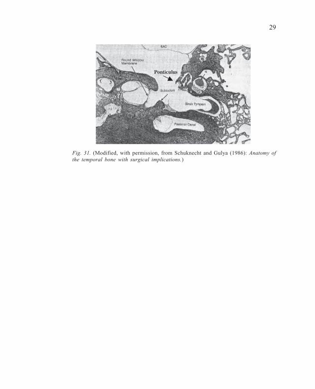
Posterior mesotympanumAs mentioned above, this is the most hidden area of the TB, which canonly be exposed after destructive steps have been taken. In fact, thisregion lies medial to the FN canal (vertical or mastoid segment) andanterior to the posterior semicircular canal (PSC). Other than the twomajor depressions in the posteromedial wall of the tympanic cavity,namely the round and oval window niches, the posterior mesotympanumis often named after only one part of it, the so-called sinus tympani. Itlies between the ponticulus, which bridges the gap between the pyra-midal eminence and the promontory superiorly, and the subiculum, aridge stretching inferiorly between the styloid eminence to the poste-rior lip of the round window niche. The posterior depth of the sinustympani is variable, reaching several millimetres in the direction ofthe ampullary arm of the PSC (Fig. 31).
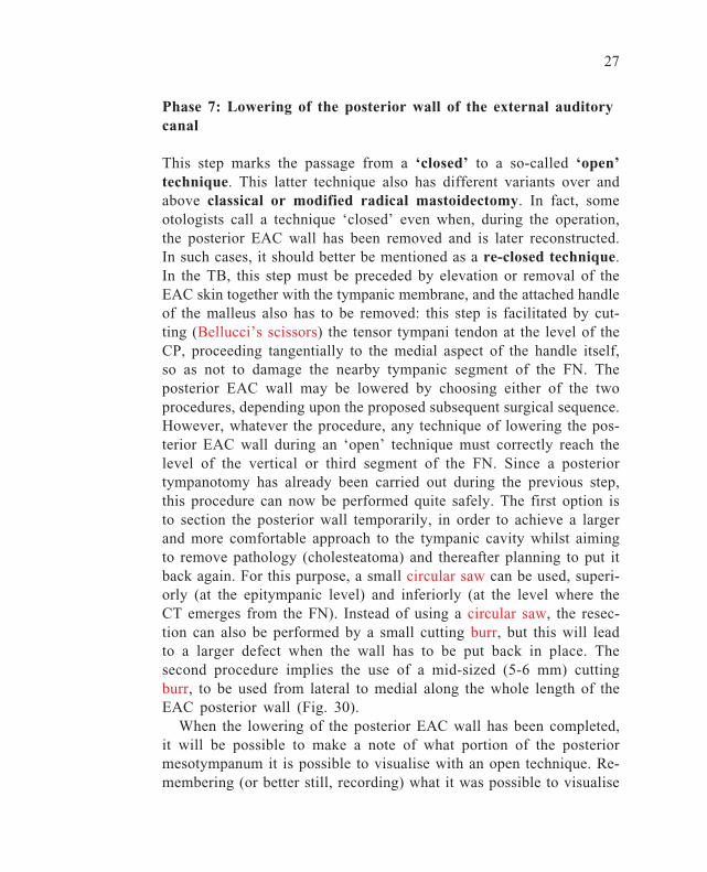
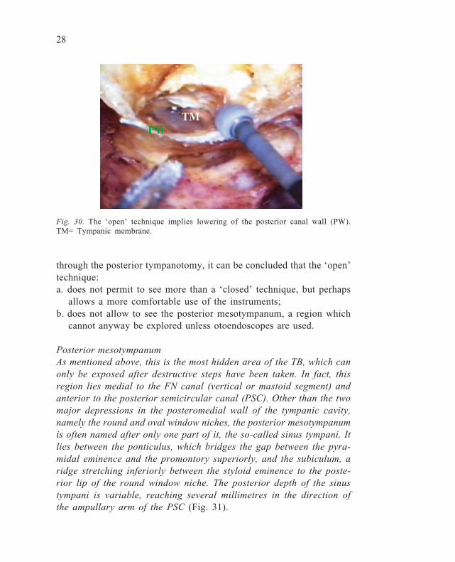
Fig. 30. The ‘open’ technique implies lowering of the posterior canal wall (PW).TM= Tympanic membrane.
29
Fig. 31. (Modified, with permission, from Schuknecht and Gulya (1986): Anatomy ofthe temporal bone with surgical implications.)
30
Phase 8: Classical radical mastoidectomy
If it is true that the clinical indications for a ‘radical’ mastoidectomyare becoming fewer and fewer nowadays, it is also true that parts ofthis surgical technique may be included as steps in other, mostlyneurootological approaches, and must therefore be part of the techni-cal armamentarium of an otologist.
At the end of Phase 7, we have a cavity mimicking a modifiedradical, namely a technique that requires lowering of the posteriorEAC wall, at the same time sparing the existing middle ear structures(eardrum remnants, ossicles). However, a classical radical mastoidec-tomy implies the elimination of all middle ear structures (stapes orfootplate excluded). Moreover, in order to carry out the main steps ofthis dissection, all EAC walls must be freed of skin, especially in theanterior part, with laterally-based flaps that may be difficult to per-form in a cadaver bone. For an optimal ‘radical’, the following surgi-cal steps have to be carried out:a. Lowering of the posterior EAC wall (already obtained after the pre-
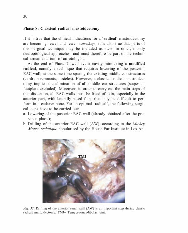
vious phase);b. Drilling of the anterior EAC wall (AW), according to the Mickey
Mouse technique popularised by the House Ear Institute in Los An-
Fig. 32. Drilling of the anterior canal wall (AW) is an important step during classicradical mastoidectomy. TMJ= Temporo-mandibular joint.
31
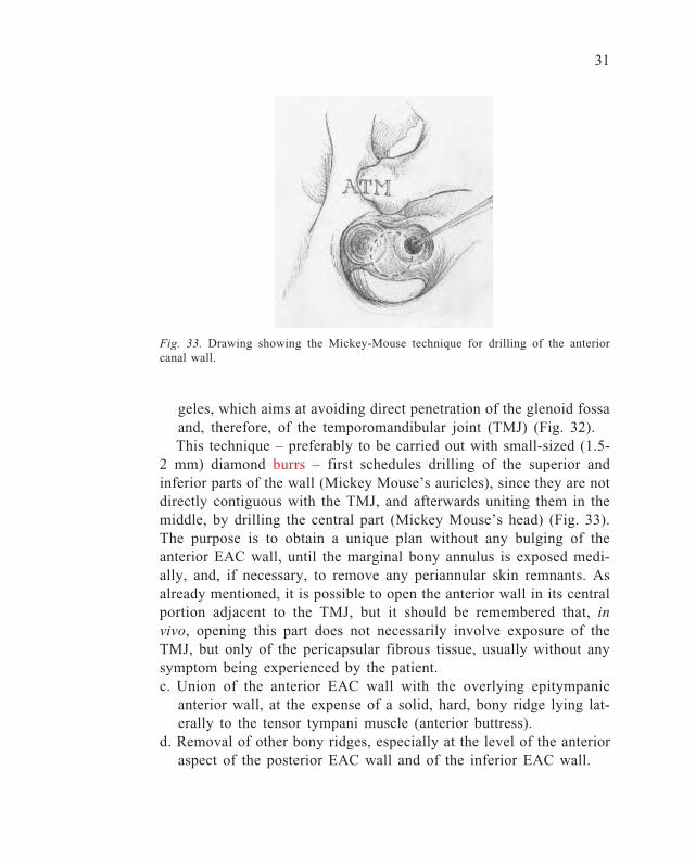
geles, which aims at avoiding direct penetration of the glenoid fossaand, therefore, of the temporomandibular joint (TMJ) (Fig. 32).This technique – preferably to be carried out with small-sized (1.5-
2 mm) diamond burrs – first schedules drilling of the superior andinferior parts of the wall (Mickey Mouse’s auricles), since they are notdirectly contiguous with the TMJ, and afterwards uniting them in themiddle, by drilling the central part (Mickey Mouse’s head) (Fig. 33).The purpose is to obtain a unique plan without any bulging of theanterior EAC wall, until the marginal bony annulus is exposed medi-ally, and, if necessary, to remove any periannular skin remnants. Asalready mentioned, it is possible to open the anterior wall in its centralportion adjacent to the TMJ, but it should be remembered that, invivo, opening this part does not necessarily involve exposure of theTMJ, but only of the pericapsular fibrous tissue, usually without anysymptom being experienced by the patient.c. Union of the anterior EAC wall with the overlying epitympanic
anterior wall, at the expense of a solid, hard, bony ridge lying lat-erally to the tensor tympani muscle (anterior buttress).
d. Removal of other bony ridges, especially at the level of the anterioraspect of the posterior EAC wall and of the inferior EAC wall.
Fig. 33. Drawing showing the Mickey-Mouse technique for drilling of the anteriorcanal wall.
32
Before leaving the ‘radical’ phase, it is important to remember thatan essential non-osseous surgical step is represented by meatoplasty,namely widening of the outer orifice of the EAC, some of which hasto be done by removal of the conchal cartilage.
The next phase is the first of three, which are not generally in-cluded in the dissection steps of basic courses. However, since thedissection is medial to the promontory wall, it is propitious thatotosurgeons obtain knowledge of it for at least two reasons:1. to be able to deal with unusual pathological (cholesteatoma eroding
the medial wall of the tympanic cavity) or anatomical (e.g., a highjugular bulb) situations;
2. to be familiar with the three-dimensional orientation of the cochleafor cochlear implant surgery, with both normal and malformed orossified cochleas.
33
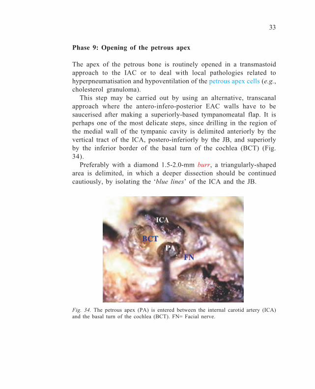
Phase 9: Opening of the petrous apex
The apex of the petrous bone is routinely opened in a transmastoidapproach to the IAC or to deal with local pathologies related tohyperpneumatisation and hypoventilation of the petrous apex cells (e.g.,cholesterol granuloma).
This step may be carried out by using an alternative, transcanalapproach where the antero-infero-posterior EAC walls have to besaucerised after making a superiorly-based tympanomeatal flap. It isperhaps one of the most delicate steps, since drilling in the region ofthe medial wall of the tympanic cavity is delimited anteriorly by thevertical tract of the ICA, postero-inferiorly by the JB, and superiorlyby the inferior border of the basal turn of the cochlea (BCT) (Fig.34).
Preferably with a diamond 1.5-2.0-mm burr, a triangularly-shapedarea is delimited, in which a deeper dissection should be continuedcautiously, by isolating the ‘blue lines’ of the ICA and the JB.
Fig. 34. The petrous apex (PA) is entered between the internal carotid artery (ICA)and the basal turn of the cochlea (BCT). FN= Facial nerve.
34
Phase 10: Cochleostomy and cochlear visualisation
This phase of the dissection contains anatomical and practical elementswith respect to cochlear implant surgery. Looking at the medial wallof the tympanic cavity, everyone knows that the promontory (a con-vex area) corresponds to part of the basal turn of the cochlea. Thesurgical landmarks for the identification of the deep projection of thecochlea are:• round window (RW) niche• stapes (S) and oval window (OW)• cochleariform process (CP)• semicanal of the tensor tympani muscle (STTM)• tubal orifice (TO)• vertical trait of the ICA• Jacobson’s nerve (J)
It is important to remember that the baso-apical direction of thecochlear turn is opposite to the side operated: left direction in a rightcochlea and vice versa. The initial step consists of cochleostomy, inaccordance with the modalities of cochlear implant surgery. A small(2 mm) diamond burr is placed 1 mm up and 2 mm anterior to the lipof the RW niche, and kept in place while slight pressure is exerted. Atthat level, the bone of the otic capsule is very compact and hard topenetrate. After having created a niche, a smaller (also cutting) burr ischosen and drilling continues, always keeping the tip of the drill push-ing slightly on the bone (remember that this is one of the few excep-tions when the burr is not working as usual, i.e., with the shoulderand with oscillating strokes). Carrying on, with the burr working per-pendicularly to the promontory wall, the endocochlear cavity is finallyentered at the level of the scala tympani (in laboratory bones, no peri-lymph leakage will be observed) (Fig. 35a-b).
At times, before entering the cavity, the endosteum may first beexposed, in accordance with the ‘soft surgery’ procedure advised tominimise cochlear trauma. At this point, it is possible to widen thehole, being careful not to hit the bony spiral lamina and the basilarmembrane located in the posterosuperior pole of the cochleostomy,since their damage could interfere with the outcome of cochlear im-plant function. If a dummy is available, it is possible to try to simu-

35
Fig. 35a. With a small (1.8 mm) diamondburr, cochleostomy is performed.
late its insertion, ending with the application, before starting with theanatomical dissection of the cochlea.
This step is carried out by using a diamond burr, and removal ofthe superficial part of the cochlear wall is continued anteriorly up tothe projecting area of the ICA, and then superiorly in the region whichis medial to the pathway between the CP and the semicanal of thetensor tympani muscle. At this level, care should be taken not to pen-etrate the MCF dura, remembering the strict relationship between theanterosuperior margin of the apical cochlear area, the geniculate gan-glion, and the semicanal itself. In order to dissect and visualise theentire cochlea, it is also necessary to remove the stapes and to widenthe drilling posterosuperiorly: it is important to acknowledge the cen-tral bearing axis (the modiolus), obliquely oriented from bottom totop, posteroanteriorly and mediolaterally (Fig. 36). If magnification is
J
Fig. 36. The lateral aspect of the cochlea has been removed and the cochlear turnsare shown around the modiolus (MA). STTM= Semicanal of the tensor tympanimuscle; CP= Cochleariform process; OW= Oval window; RW: Round window.
Fig. 35b. The arrow shows the directionof the basal turn of the cochlea.
36
increased to the maximum (40x), unimaginable cochlear structures canbe recognised (basilar membrane, scala tympani and vestibuli, pig-mentation of the inner ear structures).
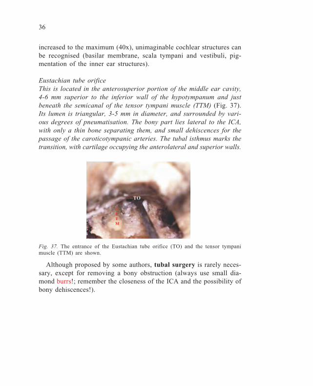
Eustachian tube orificeThis is located in the anterosuperior portion of the middle ear cavity,4-6 mm superior to the inferior wall of the hypotympanum and justbeneath the semicanal of the tensor tympani muscle (TTM) (Fig. 37).Its lumen is triangular, 3-5 mm in diameter, and surrounded by vari-ous degrees of pneumatisation. The bony part lies lateral to the ICA,with only a thin bone separating them, and small dehiscences for thepassage of the caroticotympanic arteries. The tubal isthmus marks thetransition, with cartilage occupying the anterolateral and superior walls.
Fig. 37. The entrance of the Eustachian tube orifice (TO) and the tensor tympanimuscle (TTM) are shown.
Although proposed by some authors, tubal surgery is rarely neces-sary, except for removing a bony obstruction (always use small dia-mond burrs!; remember the closeness of the ICA and the possibility ofbony dehiscences!).
37
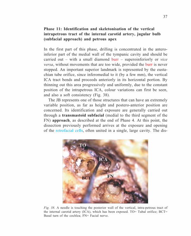
Phase 11: Identification and skeletonisation of the verticalintrapetrous tract of the internal carotid artery, jugular bulb(subfacial approach) and petrous apex
In the first part of this phase, drilling is concentrated in the antero-inferior part of the medial wall of the tympanic cavity and should becarried out – with a small diamond burr – superoinferiorly or viceversa, without movements that are too wide, provided the burr is neverstopped. An important superior landmark is represented by the eusta-chian tube orifice, since inferomedial to it (by a few mm), the verticalICA tract bends and proceeds anteriorly in its horizontal portion. Bythinning out this area progressively and uniformly, due to the constantposition of the intrapetrous ICA, colour variations can first be seen,and also a soft consistency (Fig. 38).
The JB represents one of those structures that can have an extremelyvariable position, as far as height and postero-anterior position areconcerned. Its identification and exposure are generally carried outthrough a transmastoid subfacial (medial to the third segment of theFN) approach, as described at the end of Phase 4. At this point, thedissection previously performed arrives at the exposure and openingof the retrofacial cells, often united in a single, large cavity. The dis-
Fig. 38. A needle is touching the posterior wall of the vertical, intra-petrous tract ofthe internal carotid artery (ICA), which has been exposed. TO= Tubal orifice; BCT=Basal turn of the cochlea; FN= Facial nerve.
BCT
38
section will then proceed anteromedially, having as its lateral limit thethird portion of the FN, and as its upper limit, the labyrinthine block,and more specifically, the ampullary arm of the PSC. In order to optimisevisualisation of the region to be opened, it is appropriate to tilt thespecimen (in surgery, the operating bed) anteriorly. This manoeuvrewill depend upon the degree of dissection of the retrosinus mastoidec-tomy, the posterior margin of which should not hamper visibility ofthe anterior regions. When necessary, at this point, further drilling ofthe posterior margin of the cavity should be carried out until this goalhas been achieved. Once the JB has been identified, it is possible to godeeper, using smaller calibre (1-2 mm) diamond burrs, always beingcareful not to open the labyrinth (PSC). Apart from being smaller, theburrs should also have a longer shaft. It is thus possible to reach andopen the petrous apex cells, finding an extreme variability of pneuma-tisation at this level.
39
Phase 12: Facial nerve decompression (second and thirdportions)
As shown so far, the FN represents the structure around which thewhole TB dissection rotates. It is important not to forget that the bestmethod for preventing damage to the FN is always to keep looking forit. Apart from the monitoring systems performed during live surgery,one sign that should alert the surgeon and make him realise that he/sheis close to the FN is the mild, sometimes annoying, bleeding along itscourse (obviously, never coagulate! Await its spontaneous remission!).Another important concept is not to fear facial palsy if, when lookingfor the nerve, it is uncovered: on the contrary, this can be useful toavoid damaging it.
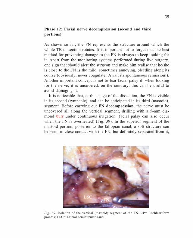
It is noticeable that, at this stage of the dissection, the FN is visiblein its second (tympanic), and can be anticipated in its third (mastoid),segment. Before carrying out FN decompression, the nerve must beuncovered all along the vertical segment, drilling with a 5-mm dia-mond burr under continuous irrigation (facial palsy can also occurwhen the FN is overheated) (Fig. 39). In the superior segment of themastoid portion, posterior to the fallopian canal, a soft structure canbe seen, in close contact with the FN, but definitely separated from it,
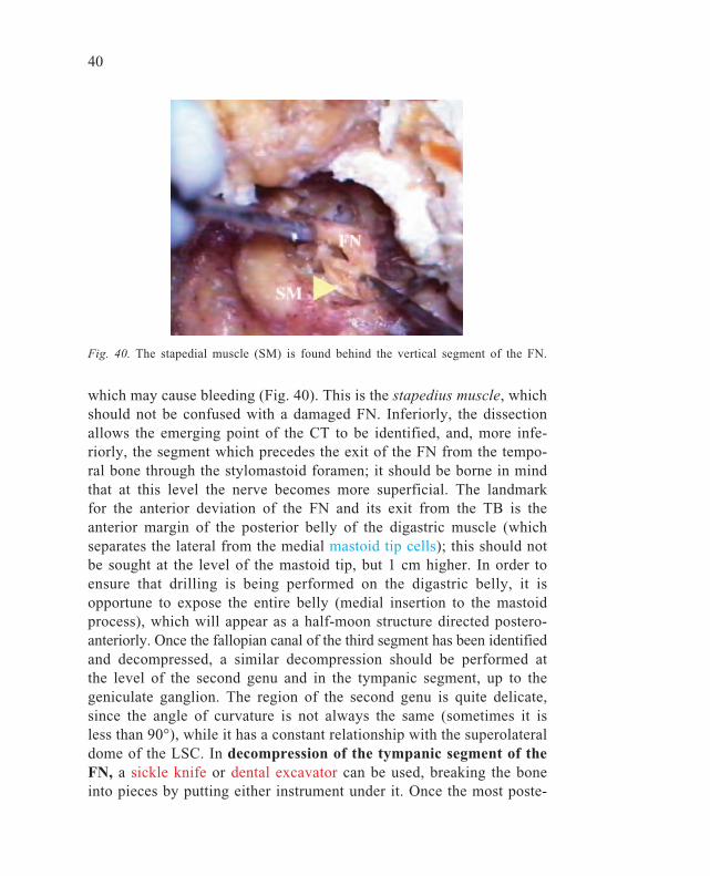
Fig. 39. Isolation of the vertical (mastoid) segment of the FN. CP= Cochleariformprocess; LSC= Lateral semicircular canal.
40
which may cause bleeding (Fig. 40). This is the stapedius muscle, whichshould not be confused with a damaged FN. Inferiorly, the dissectionallows the emerging point of the CT to be identified, and, more infe-riorly, the segment which precedes the exit of the FN from the tempo-ral bone through the stylomastoid foramen; it should be borne in mindthat at this level the nerve becomes more superficial. The landmarkfor the anterior deviation of the FN and its exit from the TB is theanterior margin of the posterior belly of the digastric muscle (whichseparates the lateral from the medial mastoid tip cells); this should notbe sought at the level of the mastoid tip, but 1 cm higher. In order toensure that drilling is being performed on the digastric belly, it isopportune to expose the entire belly (medial insertion to the mastoidprocess), which will appear as a half-moon structure directed postero-anteriorly. Once the fallopian canal of the third segment has been identifiedand decompressed, a similar decompression should be performed atthe level of the second genu and in the tympanic segment, up to thegeniculate ganglion. The region of the second genu is quite delicate,since the angle of curvature is not always the same (sometimes it isless than 90°), while it has a constant relationship with the superolateraldome of the LSC. In decompression of the tympanic segment of theFN, a sickle knife or dental excavator can be used, breaking the boneinto pieces by putting either instrument under it. Once the most poste-
Fig. 40. The stapedial muscle (SM) is found behind the vertical segment of the FN.
41
rior part has been decompressed, it is easier to carry out the moreanterior part. After isolation of the second and third segments of theFN from the bony canal, the next step is to open the mid-lateral por-tion of the epineurial sheath (with a sickle knife or No. 11 scalpel),like an open book, leaving the most medial portion intact. Osteo-epineurialdecompression of the most anterior second segment will allow the strictrelationship between two soft tissue components to be visualised: theexposed FN and the underlying tensor tympani muscle. At this point,after setting the medial adherences in the fallopian canal free with asickle knife or Rosen needle, it will be possible to raise both the sec-ond and third segments altogether, thus mimicking anterior reroutingof the FN, which is carried out, for example, in glomus tumour surgeryor cholesteatoma surgery, when removing cholesteatoma that extendmedially to the fallopian canal.
42
Phase 13: Identification of the endolymphatic sac
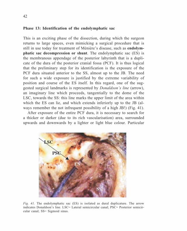
This is an exciting phase of the dissection, during which the surgeonreturns to large spaces, even mimicking a surgical procedure that isstill in use today for treatment of Ménière’s disease, such as endolym-phatic sac decompression or shunt. The endolymphatic sac (ES) isthe membranous appendage of the posterior labyrinth that is a dupli-cate of the dura of the posterior cranial fossa (PCF). It is thus logicalthat the preliminary step for its identification is the exposure of thePCF dura situated anterior to the SS, almost up to the JB. The needfor such a wide exposure is justified by the extreme variability ofposition and course of the ES itself. In this regard, one of the sug-gested surgical landmarks is represented by Donaldson’s line (arrow),an imaginary line which proceeds, tangentially to the dome of theLSC, towards the SS: this line marks the upper limit of the area withinwhich the ES can lie, and which extends inferiorly up to the JB (al-ways remember the not infrequent possibility of a high JB!) (Fig. 41).
After exposure of the entire PCF dura, it is necessary to search fora thicker or darker (due to its rich vascularisation) area, surroundedupwards and downwards by a lighter or light blue colour. Particular
Fig. 41. The endolymphatic sac (ES) is isolated as dural duplicature. The arrowindicates Donaldson’s line. LSC= Lateral semicircular canal; PSC= Posterior semicir-cular canal; SS= Sigmoid sinus.
43
attention must be paid to not penetrating the PSC which, in some TB,may be close to an anteriorly located SS. Once the presumed ES areahas been identified, it is necessary to follow it cautiously anteriorly,using a small curette or a small diamond burr on the posteromedialaspect of the PSC. The ES will certainly have been found when –depressing the corresponding dura – the surgeon can see the anteriorprolongation medially to the labyrinthine block (PSC), which is stillthe ES and not yet the duct (ED).
44
Fig. 42. The labyrinthine block. LSC= Lateral semicircular canal; SSC= Superiorsemicircular canal; PSC= Posterior semicircular canal.
Phase 14: Isolation of the labyrinthine block
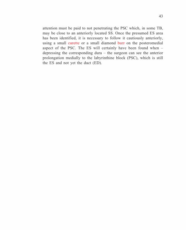
Drilling of the pre-sinus cells, performed to expose the PCF dura aboveDonaldson’s line as well, enables the posterior edge of the posteriorlabyrinthine block to be reached; this is represented by the three semi-circular canals (SCs). At this point, their spatial orientation can beestimated, taking into account the dome of the LSC, visualised withthe antral opening. Isolation of the three SCs is therefore obtained bydelineating their tridimensional projection. As already noted, both colourand compactness of the otic capsule bone differ from that of the sur-rounding cellular or acellular bone, being glossy yellow and harder(Fig. 42).
It is important to remember that the three SCs are located in thethree spatial planes, perpendicular to one another, and that their namerefers to the orientation of their dome. Hence, they are not at the samelevel, but rather at a different depth: the most superficial is the LSC,while the level of the PSC lies halfway to the non-ampullary arm ofthe LSC. The common crus of the PSC is much deeper, while thelevel of the superior semicircular canal (SSC) is the deepest of thethree. During drilling of the central part of the SSC, a small channel
45
containing the subarcuate artery (SA), a branch of the anterio-inferiorcerebellar artery (AICA), will be encountered, which is a useful land-mark for subsequent drilling, since it is equidistant from the course ofthe SSC, being situated in its centre. Before isolating the SSC, it isvery important to skeletonise the tegmental line thoroughly (at thatlevel, the tegmen antri).
It must be remembered that each SC is surrounded by pneumatisedor sclerotic bone, which covers the bony otic capsule. Isolation of thethree SCs will be improved after exenterating the perilabyrinthine cellgroups.

46
Phase 15: Labyrinthectomy and identification of theintraosseous endolymphatic sac and duct
Labyrinthectomy consists of the total destruction of all SCs and shouldbe associated with the removal of saccular and utricular receptors. Al-ready exposed, the SCs must be drilled away in the same order, whichcan start from either the LSC or the PSC. The PSC can also representthe starting point for a surgical approach recently popularised in thoserare cases of benign paroxysmal positional vertigo (BPPV) that cannotbe controlled with classical positional manoeuvres: occlusion of thePSC, which consists of drilling the dome of the PSC and progressiveintraluminal blockage with a gelfoam-type material. Thus, by performingcareful opening of the PSC, a disputable but codified surgical proce-dure is being carried out. The LSC may also be the first canal to beopened, since it is clearly evident in the antral cavity since the firststeps of the dissection. In principle, the opening of the SCs must pro-ceed by highlighting – over its entire length – the groove containingthe membranous labyrinth. The strict anatomical relationship betweenthe LSC and the FN, which always lies inferomedial to it, must beborne in mind. In order to prevent a cutting burr from damaging theFN, three main rules should be adhered to:
a. in a right ear, change the rotation of the burr, so that if it shouldinadvertently slip, it is directed away from the nerve;
b. drill on its superior side, because drilling laterally may jeopardisethe FN;
c. move the burr on the main axis of the canal.
After having exposed the groove of the LSC and PSC, it will be notedthat the non-ampullary arm of the latter (common crus with SSC) lieson a deeper plane than the ampullary one. At this point, drilling of theSSC should be continued, with attention being paid that the MCF dura,which is in close contact with its dome, does not get torn (arcuateeminence (AE) in the MCF approach) (Fig. 43).
It is only after having exposed the internal part of the three SCs inthis way, that the dissection should proceed by their total removal.From an anatomical point of view, as labyrinthectomy proceeds, itwill be possible to see, medially to the PSC, the anterior prolongationof the ES (intra-osseous portion), as a thin whitish channel which
47
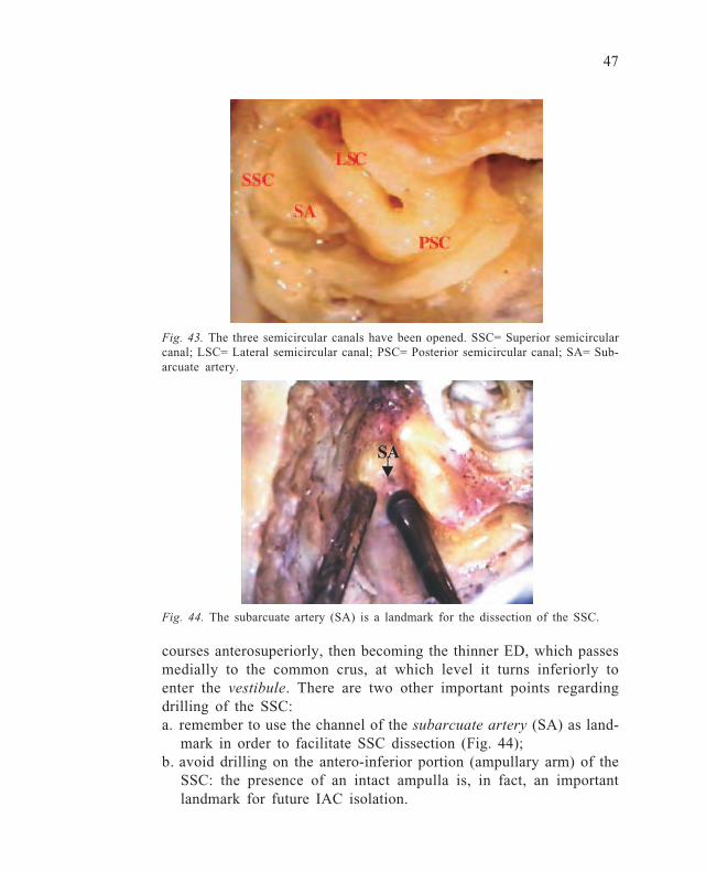
Fig. 43. The three semicircular canals have been opened. SSC= Superior semicircularcanal; LSC= Lateral semicircular canal; PSC= Posterior semicircular canal; SA= Sub-arcuate artery.
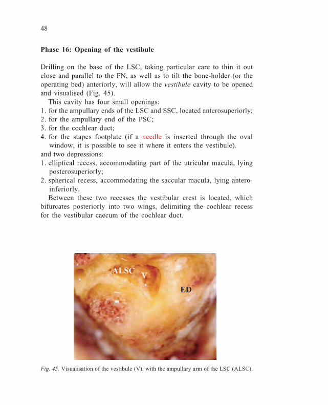
courses anterosuperiorly, then becoming the thinner ED, which passesmedially to the common crus, at which level it turns inferiorly toenter the vestibule. There are two other important points regardingdrilling of the SSC:a. remember to use the channel of the subarcuate artery (SA) as land-
mark in order to facilitate SSC dissection (Fig. 44);b. avoid drilling on the antero-inferior portion (ampullary arm) of the
SSC: the presence of an intact ampulla is, in fact, an importantlandmark for future IAC isolation.
Fig. 44. The subarcuate artery (SA) is a landmark for the dissection of the SSC.
48
Phase 16: Opening of the vestibule
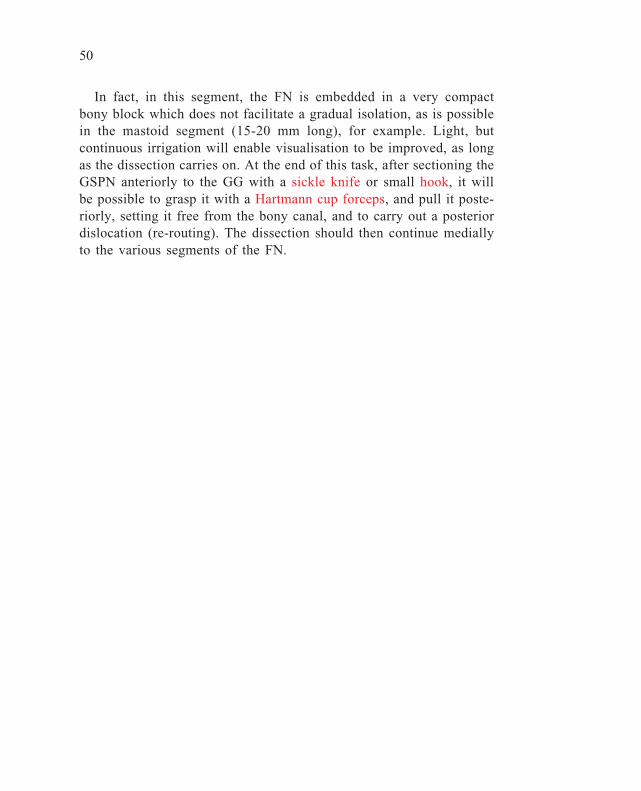
Drilling on the base of the LSC, taking particular care to thin it outclose and parallel to the FN, as well as to tilt the bone-holder (or theoperating bed) anteriorly, will allow the vestibule cavity to be openedand visualised (Fig. 45).
This cavity has four small openings:1. for the ampullary ends of the LSC and SSC, located anterosuperiorly;2. for the ampullary end of the PSC;3. for the cochlear duct;4. for the stapes footplate (if a needle is inserted through the oval
window, it is possible to see it where it enters the vestibule).and two depressions:1. elliptical recess, accommodating part of the utricular macula, lying
posterosuperiorly;2. spherical recess, accommodating the saccular macula, lying antero-
inferiorly.Between these two recesses the vestibular crest is located, which
bifurcates posteriorly into two wings, delimiting the cochlear recessfor the vestibular caecum of the cochlear duct.
Fig. 45. Visualisation of the vestibule (V), with the ampullary arm of the LSC (ALSC).

49
Phase 17: Identification of the labyrinthine segment of the facialnerve
After the previous steps of the dissection, the FN is decompressedosteo-epineurially and is lifted from the fallopian canal, thus havingonly two anchoring points:• its exit at the stylomastoid foramen;• at the level of the geniculate ganglion (GG).
In order to allow its complete mobilisation (re-routing), not only an-teriorly, but also posteriorly, the following dissection exercises mustbe performed:1. identify the GG with its anterior prolongation, the greater superfi-
cial petrosal nerve (GSPN), which has to be severed;2. decompress the labyrinthine segment (the shortest one, 3-4 mm, but
also the most delicate), up to the entrance in the IAC.The first aim is reached by decompressing the most anterior part of
the tympanic segment (12-13 mm long), above the cochleariform pro-cess (CP), opening the space delimited inferolaterally by the tympanicFN, superolaterally by the MCF dura, and posteriorly by the superiorprelabyrinthine cells and the SSC. Dissection of the labyrinthine FNshould not be hurried, since the nerve can easily be avulsed (Fig. 46).
Fig. 46. Isolation of the labyrinthine segment of the FN (LFN). GG= Geniculateganglion; SSC= Superior semicircular canal; CP= Cochleariform process; TFN= Tym-panic segment of the facial nerve.
50
In fact, in this segment, the FN is embedded in a very compactbony block which does not facilitate a gradual isolation, as is possiblein the mastoid segment (15-20 mm long), for example. Light, butcontinuous irrigation will enable visualisation to be improved, as longas the dissection carries on. At the end of this task, after sectioning theGSPN anteriorly to the GG with a sickle knife or small hook, it willbe possible to grasp it with a Hartmann cup forceps, and pull it poste-riorly, setting it free from the bony canal, and to carry out a posteriordislocation (re-routing). The dissection should then continue mediallyto the various segments of the FN.
51
Phase 18: Identification and opening of the internal auditorycanal
This is the final dissection on a TB approached from its lateral aspect.It is one of the most delicate and difficult steps, in which smaller andsmaller diamond burrs have to be used on a more and more compactbone.
The dissection aims at isolating the IAC for 270° or more, in itsposterior, superior, and inferior aspects. While the posterior limit isdelineated by the dural reflection of the PCF with the IAC dura, thetwo other well-codified landmarks for extension and facilitation of thedissection are:a. superiorly, the ampulla of SSC, which should not be sacrificed dur-
ing labyrinthectomy because it is important for identification of theentrance of the FN in the IAC;
b. inferiorly, the orifice of the cochlear aqueduct; if the dissection isbrought below this point, there may be damage to the pars nervosaof the jugular foramen (IX, X and XI cranial nerves).However, the dissection must start posteriorly, in the area corre-
sponding to the posterior labyrinth (SCs), remembering that the posi-tion of the IAC is always more anterior than may be realised. Tomake it easier to visualise, remember the definition in Gray’s* En-glish-language anatomical textbook, which states: “If you put a pencilin the EAC, and push it medially, you will find it in the IAC.” Basi-cally, the roof of the IAC is represented by the medial wall of thevestibule, where the posterior edge will delimit the posterosuperiorborder of the IAC superficially (laterally). A diamond, mid-calibre(8-10 mm) burr may be used, as well as analogous cutting ones. Atthis point, the bone is very thick and compact, and gentle pressureshould also be exerted during drilling: a diamond burr will avoid tearingthe underlying dura, which has to be completely uncovered. A cuttingburr cannot avoid this. The following consideration should be bornein mind during all phases of the dissection: to hurry a dissection,especially in the case of an inexperienced surgeon, is never with-out danger.
* Anatomist at St George’s Hospital Medical School, London (1821-1865).

52
Superior and inferior dissections of the IAC are the most difficultstages in a TB dissection due to:• working with a small-sized diamond burr;• increasing postero-anterior thickness;• the closeness of the soft tissues with possible minor (tearing of PCF
or MCF dura) or major (IAC penetration, with neural or vesselinvolvement) damage.During this step, the suction-irrigation tip can also be used as an
instrument since it helps to move the acoustic-facial package awayfrom the drilling zone. As has been pointed out above, when drillingon the IAC, the burr does not work in the usual (uniform and continu-ous strokes) way, but rather by means of a contact-and-pressure ac-tion, and sometimes with the tip as well. When the bone has beenthinned out, a ‘blue-line’ may also have been produced, this colourbeing due to the underlying fluid-immersed tissue.
Once isolation of the IAC dural surface is complete, the entrance ofthe labyrinthine FN into the IAC – in its superolateral part – can beidentified. The dural layer of the IAC is then opened with a smallhook, and the following four neural elements can be seen (Fig. 47-48):• facial nerve (FN), antero-superiorly;• cochlear nerve (CN), antero-inferiorly;• superior vestibular nerve (SVN), postero-superiorly; and• inferior vestibular nerve (IVN) postero-inferiorly.
Fig. 47. Bill’s bar (BB) divides the facialnerve (FN) from the superior vestibular (SV)nerve.
Fig. 48. Removal of the two vestibularnerves allows visualisation of the ante-rior IAC compartment which includes thecochlear (CN) and the facial (FN) nerves.
53
It is also possible to visualise the vertical crest – also known asBill’s bar (B) after William House – which separates the FN from theSVN, as well as the transverse crest (TC), which separates the SVNfrom the IVN.
When this final part of the dissection has been achieved, the lateralapproach to the TB is completed. The various steps of the dissectionhave been interspersed with true surgical approaches in order to ren-der the dissection more stimulating and interesting, in the view of theauthor.
54
SUPRATEMPORAL OR MIDDLE FOSSAAPPROACH
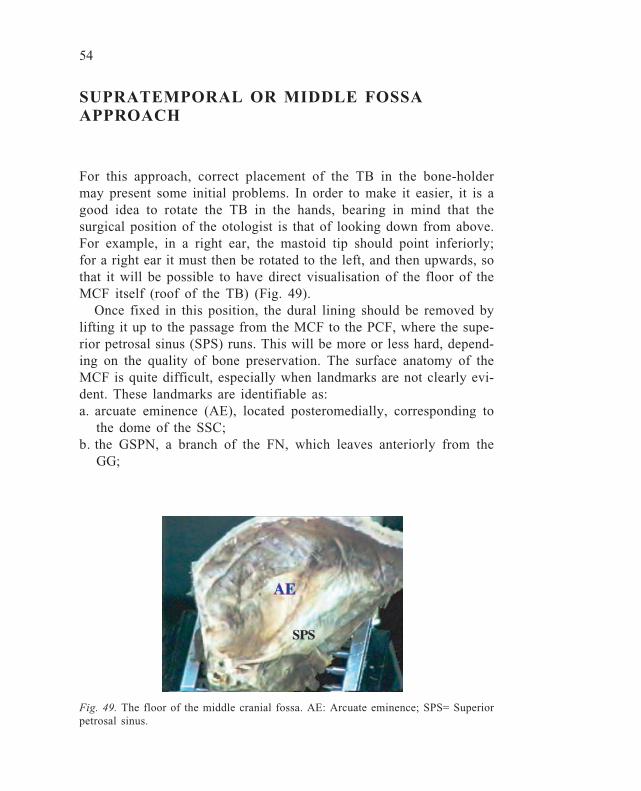
For this approach, correct placement of the TB in the bone-holdermay present some initial problems. In order to make it easier, it is agood idea to rotate the TB in the hands, bearing in mind that thesurgical position of the otologist is that of looking down from above.For example, in a right ear, the mastoid tip should point inferiorly;for a right ear it must then be rotated to the left, and then upwards, sothat it will be possible to have direct visualisation of the floor of theMCF itself (roof of the TB) (Fig. 49).
Once fixed in this position, the dural lining should be removed bylifting it up to the passage from the MCF to the PCF, where the supe-rior petrosal sinus (SPS) runs. This will be more or less hard, depend-ing on the quality of bone preservation. The surface anatomy of theMCF is quite difficult, especially when landmarks are not clearly evi-dent. These landmarks are identifiable as:a. arcuate eminence (AE), located posteromedially, corresponding to
the dome of the SSC;b. the GSPN, a branch of the FN, which leaves anteriorly from the
GG;
Fig. 49. The floor of the middle cranial fossa. AE: Arcuate eminence; SPS= Superiorpetrosal sinus.
55
c. the GG, sometimes devoid of bone covering, which occupies a cen-tral position on the floor of the MCF;
d. the middle meningeal artery (MMA), a branch of the external ca-rotid artery, which exits from the foramen spinosum positioned inthe most anterior part of the surgical field.In cases of difficult orientation, it may be necessary to find the way
by drilling regions not directly correlated with the surgical objective.The most inferior part, covered by more or less compact bone, is oc-cupied by the tegmen, which lines the superior epitympanic wall (andposteriorly the mastoid part). Anteriorly, in a medial projection, theeustachian tube can be found.
The following phases will be presented:• opening of the epitympanic cavity and of the petrous apex cells;• identification of the FN and GG;• exposure of the IAC;• isolation of the cochlea.
56
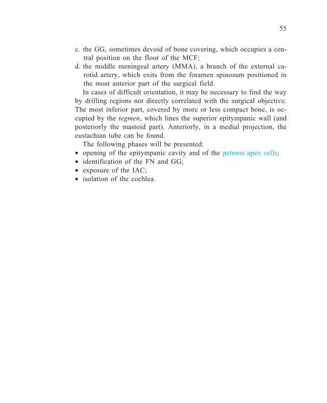
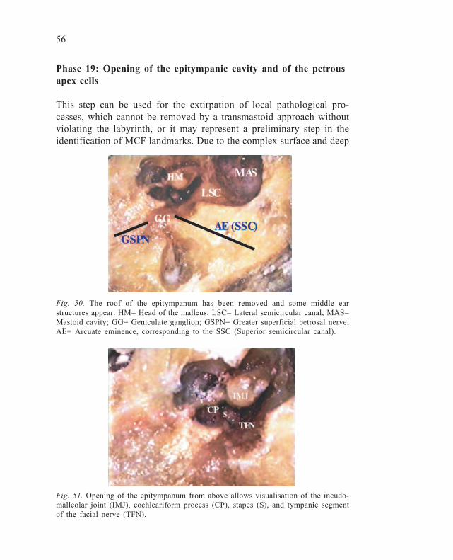
Fig. 51. Opening of the epitympanum from above allows visualisation of the incudo-malleolar joint (IMJ), cochleariform process (CP), stapes (S), and tympanic segmentof the facial nerve (TFN).
Phase 19: Opening of the epitympanic cavity and of the petrousapex cells
This step can be used for the extirpation of local pathological pro-cesses, which cannot be removed by a transmastoid approach withoutviolating the labyrinth, or it may represent a preliminary step in theidentification of MCF landmarks. Due to the complex surface and deep
Fig. 50. The roof of the epitympanum has been removed and some middle earstructures appear. HM= Head of the malleus; LSC= Lateral semicircular canal; MAS=Mastoid cavity; GG= Geniculate ganglion; GSPN= Greater superficial petrosal nerve;AE= Arcuate eminence, corresponding to the SSC (Superior semicircular canal).

57
anatomy of the MCF, it is always preferable to use diamond, mid-calibre (5-mm) burrs, with continuous irrigation. The aperture of theepitympanum enables the head of the malleus (HM) with the body ofthe incus and the malleo-incudal joint to be seen (Fig. 50-51).
By widening the opening with smaller (2-3 mm) diamond burrs, itis then possible to visualise the stapes and CP. This also enables theprelabyrinthine, apical cells, to be entered, with care being taken notto penetrate the SSC.
58
Phase 20: Identification of the facial nerve and geniculateganglion
The previous step is of great value, since opening the epitympanummakes the following possible:• to use the tympanic FN as a landmark;• to follow the FN superiorly up to the GG.
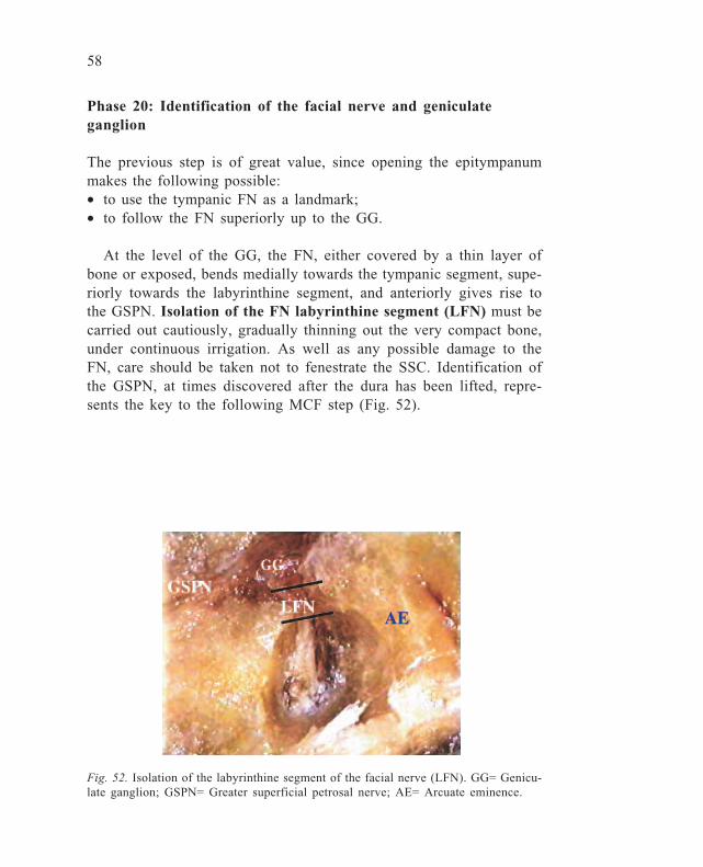
At the level of the GG, the FN, either covered by a thin layer ofbone or exposed, bends medially towards the tympanic segment, supe-riorly towards the labyrinthine segment, and anteriorly gives rise tothe GSPN. Isolation of the FN labyrinthine segment (LFN) must becarried out cautiously, gradually thinning out the very compact bone,under continuous irrigation. As well as any possible damage to theFN, care should be taken not to fenestrate the SSC. Identification ofthe GSPN, at times discovered after the dura has been lifted, repre-sents the key to the following MCF step (Fig. 52).
Fig. 52. Isolation of the labyrinthine segment of the facial nerve (LFN). GG= Genicu-late ganglion; GSPN= Greater superficial petrosal nerve; AE= Arcuate eminence.
59
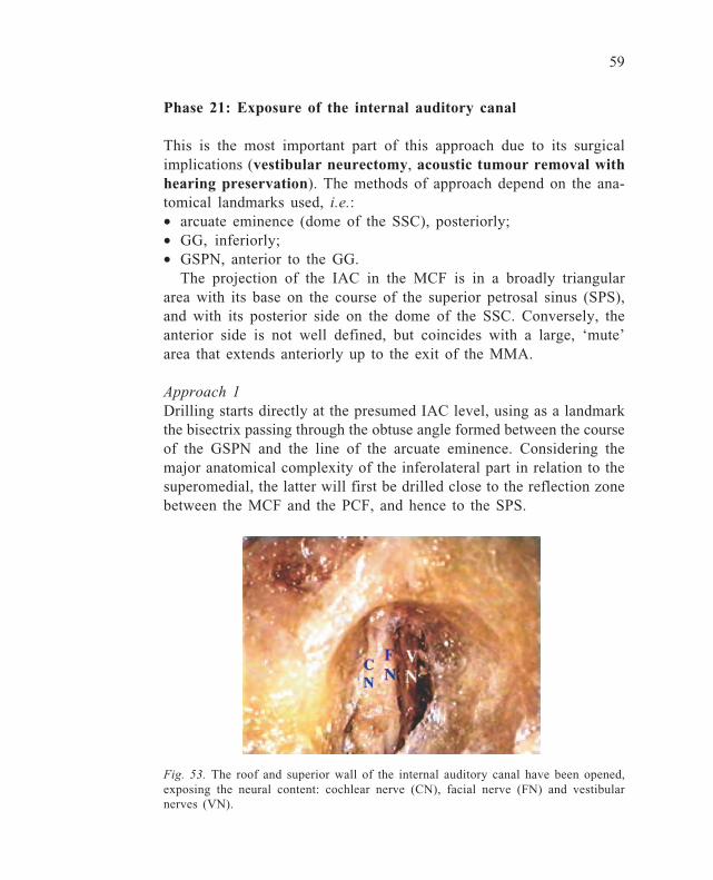
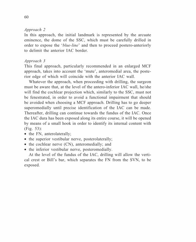
Fig. 53. The roof and superior wall of the internal auditory canal have been opened,exposing the neural content: cochlear nerve (CN), facial nerve (FN) and vestibularnerves (VN).
Phase 21: Exposure of the internal auditory canal
This is the most important part of this approach due to its surgicalimplications (vestibular neurectomy, acoustic tumour removal withhearing preservation). The methods of approach depend on the ana-tomical landmarks used, i.e.:• arcuate eminence (dome of the SSC), posteriorly;• GG, inferiorly;• GSPN, anterior to the GG.
The projection of the IAC in the MCF is in a broadly triangulararea with its base on the course of the superior petrosal sinus (SPS),and with its posterior side on the dome of the SSC. Conversely, theanterior side is not well defined, but coincides with a large, ‘mute’area that extends anteriorly up to the exit of the MMA.
Approach 1Drilling starts directly at the presumed IAC level, using as a landmarkthe bisectrix passing through the obtuse angle formed between the courseof the GSPN and the line of the arcuate eminence. Considering themajor anatomical complexity of the inferolateral part in relation to thesuperomedial, the latter will first be drilled close to the reflection zonebetween the MCF and the PCF, and hence to the SPS.
60
Approach 2In this approach, the initial landmark is represented by the arcuateeminence, the dome of the SSC, which must be carefully drilled inorder to expose the ‘blue-line’ and then to proceed postero-anteriorlyto delimit the anterior IAC border.
Approach 3This final approach, particularly recommended in an enlarged MCFapproach, takes into account the ‘mute’, anteromedial area, the poste-rior edge of which will coincide with the anterior IAC wall.
Whatever the approach, when proceeding with drilling, the surgeonmust be aware that, at the level of the antero-inferior IAC wall, he/shewill find the cochlear projection which, similarly to the SSC, must notbe fenestrated, in order to avoid a functional impairment that shouldbe avoided when choosing a MCF approach. Drilling has to go deepersuperomedially until precise identification of the IAC can be made.Thereafter, drilling can continue towards the fundus of the IAC. Oncethe IAC dura has been exposed along its entire course, it will be openedby means of a small hook in order to identify its internal content with(Fig. 53):• the FN, anterolaterally;• the superior vestibular nerve, posterolaterally;• the cochlear nerve (CN), anteromedially; and• the inferior vestibular nerve, posteromedially.
At the level of the fundus of the IAC, drilling will allow the verti-cal crest or Bill’s bar, which separates the FN from the SVN, to beexposed.
61
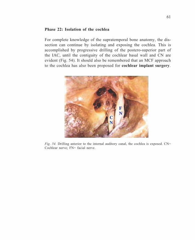
Fig. 54. Drilling anterior to the internal auditory canal, the cochlea is exposed. CN=Cochlear nerve; FN= facial nerve.
Phase 22: Isolation of the cochlea
For complete knowledge of the supratemporal bone anatomy, the dis-section can continue by isolating and exposing the cochlea. This isaccomplished by progressive drilling of the postero-superior part ofthe IAC, until the contiguity of the cochlear basal wall and CN areevident (Fig. 54). It should also be remembered that an MCF approachto the cochlea has also been proposed for cochlear implant surgery.
62
POSTERIOR CRANIAL FOSSA APPROACH
The anatomy of the posterior aspect of the TB, although not complex,presents difficulties because it uses a route which is unfamiliar to mostotosurgeons. Bearing in mind the advances in modern neurootosurgeryand the frequent contact with neurosurgeons, it is obvious that goodexperience is also necessary with this type of dissection.
The major indication is for the IAC approach, which usually fol-lows cerebellar retraction, a step that cannot be reproduced unless theentire head is available.
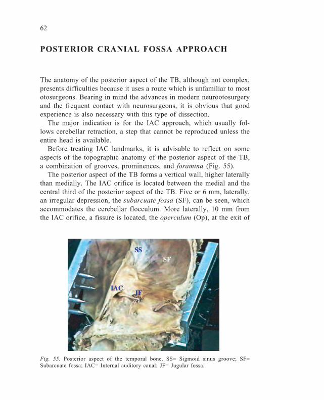
Before treating IAC landmarks, it is advisable to reflect on someaspects of the topographic anatomy of the posterior aspect of the TB,a combination of grooves, prominences, and foramina (Fig. 55).
The posterior aspect of the TB forms a vertical wall, higher laterallythan medially. The IAC orifice is located between the medial and thecentral third of the posterior aspect of the TB. Five or 6 mm, laterally,an irregular depression, the subarcuate fossa (SF), can be seen, whichaccommodates the cerebellar flocculum. More laterally, 10 mm fromthe IAC orifice, a fissure is located, the operculum (Op), at the exit of
Fig. 55. Posterior aspect of the temporal bone. SS= Sigmoid sinus groove; SF=Subarcuate fossa; IAC= Internal auditory canal; JF= Jugular fossa.

63
the vestibular aqueduct, which contains the ED and the intraosseusES, and from which the extraosseus ES emerges. Posterolaterally tothis, the groove of the SS is visible, 1 cm wide, with the mastoidregion anteriorly. More medially, close to the jugular foramen (JF),the cochlear aqueduct orifice is located (Fig. 56).
Fig. 56. The internal auditory canal (IAC) has been opened, exposing its neuralcontent. PSC= Posterior semicircular canal; ES= Endolymphatic sac region; Op= Oper-culum; JF= Jugular foramen.

64
Phase 23: Identification of the internal auditory canal
Drilling is usually carried out with the acoustic-facial package (vesti-bular neurectomy) or tumour (acoustic neuroma, meningioma) aris-ing from the vestibular nerve as the posteromedial landmark. Beforestarting drilling, the overlying dura has to be cut with a sickle knifeand then lifted anteriorly and posteriorly. With small diamond burrsand under continuous irrigation, the dissection is started in a latero-anterior direction. It is extremely important to be cautious in posteriordissections, since it is possible to injure the ES or ED, or even worsefunctionally, to fenestrate the PSC. However, since this type of ap-proach is generally selected as a last resort, this aim would not berelevant in such a case. At this same level, care must be taken regard-ing a possible high JB. Once the posterior wall of the IAC has beenidentified, drilling should go deeper both superiorly and inferiorly, inorder to expose about two-thirds of its circumference (Fig. 57). Oncethis step has been completed, a longitudinal cut will be carried outwith a No. 11 scalpel or Bellucci’s scissors, in order to open it andvisualise its content.
It is generally possible only to expose the medial two-thirds of theIAC, without running the risk of violating the vestibule or the PSC.
Fig. 57. The opened IAC. FN= Facial nerve; CN= Cochlear nerve; VNs= Vestibularnerves; VC= Vertical crest.

65
ABBREVIATIONS
A antrumAE arcuate eminenceALSC ampulla of the lateral semicircular canalAICA antero-inferior cerebellar arteryACT apical turn of the cochleaAW anterior wall of the EACBB Bill’s barBCT basal turn of the cochleaCN cochlear nerveCP cochleariform processCT chorda tympaniDM digastric muscleEAC external auditory canalED endolymphatic ductES endolymphatic sacEV emissary veinFN facial nerveGSPN greater superficial petrosal nerveHM head of the malleusIAC internal auditory canalICA internal carotid arteryIMJ incudomalleolar jointIVN inferior vestibular nerveJB jugular bulbLFN labyrinthine segment of the FNLSC lateral semicircular canalMA modiolar axisMAS mastoid cavityMCF middle cranial fossaOp operculumOW oval windowPA petrous apexPCF posterior cranial fossaPSC posterior semicircular canal
66
PW posterior wall of the EACRFC retrofacial cellsRW round windowS stapesSA subarcuate arterySC semicircular canalsSDA sinodural angleSM stapedius muscleSPS superior petrosal sinusSS sigmoid sinusSSC superior semicircular canalSTTM semicanal of the tensor tympani muscleSVN superior vestibular nerveT tip of the mastoidTB temporal boneTFN tympanic segment of the FNTO tubal orificeTL temporal lineTM tympanic membraneTMJ temporomandibular jointTT tensor tympani tendonTTM tensor tympani muscleV vestibuleZP zygomatic process
67
GLOSSARY
Arcuate eminence: bony overhang of the middle cranial fossa that cor-responds to the dome of the SSC, anatomical landmark for the identi-fication of the IAC.Bill’s bar: crest of the IAC that separates the FN from the SV nerve.Blue line: optical effect obtained when bony walls contain, or are closeto, liquid (or when they are already thin anatomically, such as normalstapes footplate) as a result of light resorption, not reflection.Buttress: thin bony wall inferior to the fossa incudis, representing thebase of the triangular zone of attack in posterior tympanotomy (facialrecess).Chipault’s cribriform area: a multiply-holed area situated posterior toHenle’s spine for the passage of small vessels, which explains theexteriorisation of antral infection to the overlying subcutaneous tissuein early childhood.COG: a half-moon shaped bony septum located just anteriorly to thehead of the malleus,which proceeds vertically from the tegmen to thedirection of the CP, without reaching it. Some authors believe that itis the outmastoid part of Koerner’s septum.Donaldson’s line: the posterior prolongation of a line passing over thedome of the LSC, marking the upper dural limit where the ES can belocalised.Facial recess: the space, delimited by the CT, FN, and fossa incudis,which has to be opened in order to gain access to the middle ear throughthe mastoid cavity (posterior tympanotomy).Koerner’s septum: or petrous-squamosal suture, a bony septum that,during mastoid development, divides the petrous (medial) from thesquamous (lateral) cells. In general, when development is complete,this septum is reabsorbed more or less completely but, in a conspicu-ous number of TBs, it may persist as a bony lamina parallel to thelateral aspect of the mastoid process. Novices may be misled and con-fuse its smooth and compact aspect with the LSC.Light refraction of the short process of the incus: an optic phenom-enon due to irrigation fluid that makes this structure visible before itactually appears in the surgical field.
68
Linea temporalis: an imaginary line that corresponds with the subtleridge of the inferior edge of the temporal muscle.MacEwen’s triangle: a triangular area on the lateral aspect of the TBwhich corresponds medially to the antral region.Metallic sound of the burr: a sound variation when a burr – especiallya cutting burr – works in close proximity to soft tissue, such as dura.Mickey Mouse technique: a dissection technique of the anterior wall ofthe EAC (in radical mastoidectomy) which implies first drilling theupper and lower parts of the wall, in order initially to avoid the cen-tral part of it – the closest to glenoid fossa, hence ATM – which isdrilled afterwards, causing the anterior wall to be flat and uniform.Posterior tympanotomy: see Facial recess.Sinodural angle-Citelli’s: a mastoid space occupied by cells (lateraland medial) which is found between the mastoid tegmen and the SS.Sinus tympani: a depression of the posterior mesotympanum, oftenidentified by its name, delimited between the ponticulus and subicu-lum.Snake’s eye: the way – as similitude – appears a flat opened dome ofthe LSC.Subarcuate fossa: a depression of the posterior aspect of the TB, ac-commodating the cerebellar flocculum.Tegmen: the bony plate that separates the mastoid and middle ear cav-ity from the middle cranial fossa dura.Transverse crest: in the IAC, this separates the superior (FN and SVN)from the inferior (CN and IVN) compartment.Vertical crest: see Bill’s bar.
69
SURGICAL APPLICATIONS
1 Antrotomy2 Enlarged mastoidectomy3 Simple mastoidectomy4 Isolation of the sigmoid sinus5. Closed tympanoplasty6 Closed tympanoplasty with mastoidectomy and posterior tympa-
notomy7 Open tympanoplasty (modified radical mastoidectomy)8 Open tympanoplasty (classic radical mastoidectomy)9 Petrous apicotomy
10. Cochlear implant11. Tubal surgery12. Facial nerve decompression (second and third segments)13. Facial nerve re-routing14. Subfacial approach15. Endolymphatic sac surgery16. Occlusion of the posterior semicircular canal17. Labyrinthectomy18. Transmastoid decompression of the labyrinthine segment of the
facial nerve19. TLB internal auditory canal isolation and exposure20. Middle cranial fossa epitympanectomy and mastoidectomy21. Middle cranial fossa decompression of the labyrinthine segment
of the facial nerve22. Middle cranial fossa neurectomy23. Posterior cranial fossa internal auditory canal exposure
70
INSTRUMENTATION
knife periosteal elevatorburrs (diamond, cutting; from 0.8-0.2 mm)suction tip (0.2, 0.4, 0.6, 0.8, 1 cm)malleus nipperBellucci’s scissorscircular sawsickle knifedental excavatorNo. 11 scalpelRosen needlecurettehooksHartmann cup forceps
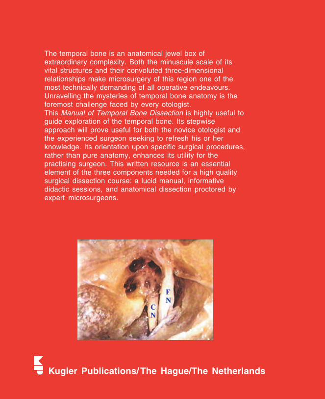
The temporal bone is an anatomical jewel box ofextraordinary complexity. Both the minuscule scale of itsvital structures and their convoluted three-dimensionalrelationships make microsurgery of this region one of themost technically demanding of all operative endeavours.Unravelling the mysteries of temporal bone anatomy is theforemost challenge faced by every otologist.This Manual of Temporal Bone Dissection is highly useful toguide exploration of the temporal bone. Its stepwiseapproach will prove useful for both the novice otologist andthe experienced surgeon seeking to refresh his or herknowledge. Its orientation upon specific surgical procedures,rather than pure anatomy, enhances its utility for thepractising surgeon. This written resource is an essentialelement of the three components needed for a high qualitysurgical dissection course: a lucid manual, informativedidactic sessions, and anatomical dissection proctored byexpert microsurgeons.
Kugler Publications/The Hague/The Netherlands
Recommended