Macro Synthetic Fibre Reinforced Ground Slabs
www.barchip.com
A Guide to the Design and Construction ofMacro Synthetic Fibre Reinforced Ground Supported Slabs
- Industrial Concrete Floors and Pavements
Revision 3: April 2018

Written by: Tommy Wong B.E. (Hons) Approved by: Edward A Bennett (NPER 198230) Date: 11/06/2014
Revised by: Ralf Winterberg MSc PhD and Todd Clarke B.E. (Hons) Approved by:Ralf Winterberg MSc PhDDate: 08/05/2017 This document is provided by BarChip Inc. for the purposes of education and guidance in the methodology behind designing ground supported slabs in accordance with the UK Concrete Society’s Technical Report 34 (TR34) 4th Edition 2013. As such BarChip recommends that upon receiving this copy that you take the time to register your details with your local BarChip representative. This will enable BarChip to provide you with updates/revisions to the document as they arise, which will maintain the accuracy and usability of this manual.
For more information, please contact:
© 2018 BarChip Inc. All Rights Reserved
Flooring Design Manual BarChip Inc. 20182
1. Introduction.....................................................................................................................................................
2. Synthetic Fibres in Concrete............................................................................................................................
2.1 General.......................................................................................................................................................
2.2 Strength Performance.................................................................................................................................
2.2.1 Compressive Strength.......................................................................................................................
2.3 Plastic Shrinkage and Settlement Cracking........................................................................................
2.4 Durability............................................................................................................................................
2.5 Concrete Mix......................................................................................................................................
2.6 Design Considerations........................................................................................................................
3. Synthetic Fibre Properties................................................................................................................................
3.1 General................................................................................................................................................
3.2 Macro Synthetic Fibres – BarChip.....................................................................................................
4. Design of Ground Supported Slabs using BarChip Fibre Reinforcement.......................................................
4.1 General...............................................................................................................................................
4.2 Partial Safety Factors..........................................................................................................................
4.3 Design Procedure Input Data (Step 1)................................................................................................
4.3.1 Strength Properties for Concrete (Step 1-1)..........................................................................
4.3.2 Flexural Tensile Strength (Step 1-2).....................................................................................
4.3.3 RadiusofRelativeStiffness(Step1-3).................................................................................
4.4 Structural Properties (Step 2).............................................................................................................
4.4.1 Negative Moment Capacity (Step 2-1)..................................................................................
4.4.2 Positive Moment Capacity with Macro Synthetic Fibre Reinforced Concrete.....................
4.4.2.1 Determining Fibre Reinforced Concrete Properties.................................................
4.4.2.2 Calculation of Residual Moment Capacity from Notched Bram Tests.....................
4.5 Select Design Loads (Step 3).............................................................................................................
4.5.1 Single Point Load (Step 3-1).................................................................................................
4.5.2 Dual Point Load (Step 3-3)...................................................................................................
4.5.3 Quadruple Point Load (Step 3-3)..........................................................................................
4.6 Punching Shear Capacity and Ground Support..................................................................................
4.6.1 General...................................................................................................................................
4.6.2 Shear at Face of Loaded Area................................................................................................
4.6.3 Shear on the Critical Perimeter..............................................................................................
4.6.4 Loadsappliedthroughastiffbearing(wherea/l<0.2).........................................................
4.7 Design of Joints ..................................................................................................................................
4.7.1 General...................................................................................................................................
Table of Contents
Flooring Design ManualBarChip Inc. 2018 3
6
8
8
8
10
11
11
12
12
15
15
15
17
17
17
18
18
19
19
20
20
21
21
22
23
24
25
26
26
26
26
27
29
30
30
4.7.2 Shear Capacity Per Dowel....................................................................................................
4.7.3 Bearing/Bending Capacity per Dowel...................................................................................
4.7.4 Bursting Force Capacity of the Dowel..................................................................................
4.8 Line Loads...........................................................................................................................................
4.9 Uniformly Distributed Loads.............................................................................................................
5. Construction of Ground Supported Slabs using BarChip Fibre Reinforcement..............................................
5.1 General ...............................................................................................................................................
5.2 Batching and Mixing..........................................................................................................................
5.2.1 Mixing at the Batch Plant with BarChip Soluble Bags.........................................................
5.2.2 Mixing at the Batch Plant with an Automatic Dosing Machine Using BarChip Pucks........
5.2.3 Mixing Fibres on-site Using BarChip Soluble Bags.............................................................
5.3 Finishing.............................................................................................................................................
5.3.1 Finishing Techniques.............................................................................................................
5.3.2 Joints and Joint Layout..........................................................................................................
5.3.3 Curing.....................................................................................................................................
6. References........................................................................................................................................................
Appendix A – Worked Design Example.......................................................................................................................
A.1 Design Example 1 – Point Loads on 150mm thick slab solely reinforced with BarChip 48 @ 4kg/m3................
A1.1.1 Step 1 – Slab Properties Part 1.............................................................................................................
A1.1.2 Step 2 – Slab Properties Part 2.............................................................................................................
A1.1.3 Step 3 – Moment Capacities................................................................................................................
A1.1.4 Step 4-1 – Single Point Load...............................................................................................................
A1.1.5 Step 4-2 – Dual Point Loads................................................................................................................
A1.1.6 Step 4-3 – Quadruple Point Loads.......................................................................................................
A1.2 Design Example 2 – Punching Shear 150 mm thick slab solely reinforced with BarChip 48 @ 4kg/m3...........
A1.2.1 Step 1 – Obtain Design Parameters.....................................................................................................
A1.2.2 Step 2 – Internal Slab...........................................................................................................................
A1.2.3 Step 3 – Edge.......................................................................................................................................
A1.2.4 Step 4 – Corner.....................................................................................................................................
A1.2.5Step5–EffectofGroundSupport(a/l<0.2)......................................................................................
A1.3 Design Example 3 – Check Load Transfer at Joints............................................................................................
A1.3.1 Step 1 – Determine Ultimate Design Point Load.................................................................................
A1.3.2 Step 2 – Determine Edge Capacity X..................................................................................................
A1.3.3 Step 3 – Determine Dowel Capacity....................................................................................................
A1.3.4Step4–TotalEffectiveEdgeCapacity................................................................................................
A1.4 Design Example 4 – Line Load Capacity.............................................................................................................
A1.5 Design Example 5 – Uniform Distributed Load/ Area Load Capacity................................................................
Appendix B - Project Case Studies...............................................................................................................................
Appendix C - Cost Comparison....................................................................................................................................
Flooring Design Manual BarChip Inc. 20184
30
31
33
33
34
35
35
35
35
35
36
36
36
36
37
38
39
40
40
40
41
42
43
44
45
45
45
46
46
47
48
48
48
49
50
50
51
52
58
Symbols
ƒck MPa = characteristic compressive cylinder strength ƒcm MPa = mean compressive cylinder strengthƒctk,flMPa= characteristicflexuraltensilestrengthƒctd,fl MPa = designflexuraltensilestrengthƒctm MPa = mean axial tensile strengthγm [-] = partial safety factor for materialsγ [-]= partialsafetyfactorforloadsa mm = equivalent radius of contact area of the loadb mm = width of standard notched beam (150 mm, as per EN 14651)d mm = racking leg width or width of vertical member carrying concentrated load. d* mm = effectivedepthofslab = 0.75hforfibrereinforcedconcreteh mm = slab thicknesshsp mm = depth of standard notched beam (125 mm)I mm4 = moment of inertial mm= radiusofrelativestiffnessl mm = span of standard notched beam (500 mm) Pu N = ultimate capacity under concentrated load P* N = ultimate design concentrated loadP*
lin kN/m = ultimate design line loadP*
UDL kN/m2 = ultimate design uniformly distributed loadu0 mm = length of the perimeter of the loaded area u1 mm = length of the critical perimetery mm = neutral axis depth of hsp section FR [-] = the applied load at stage R
Glossary of Terms and Abbreviations
Strain Compatibility Refers to concrete section under bending, where the concrete reaches its limiting compressivestrainsimultaneouslywiththefibreconcretereachingitslimitingtensile strain.
StrainSoftening Reductionintensilestressinthefibreconcreteasstrainincreases.
Flooring Design ManualBarChip Inc. 2018 5
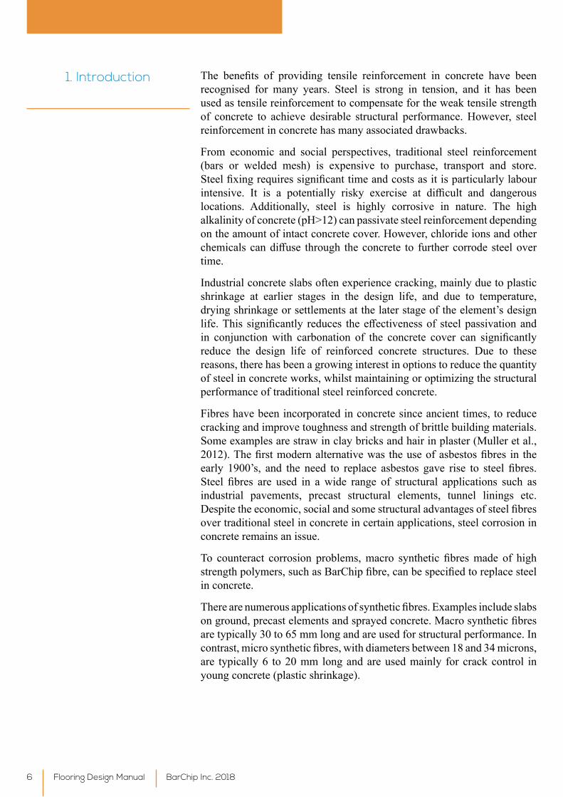
1. Introduction The benefits of providing tensile reinforcement in concrete have beenrecognised for many years. Steel is strong in tension, and it has been used as tensile reinforcement to compensate for the weak tensile strength of concrete to achieve desirable structural performance. However, steel reinforcement in concrete has many associated drawbacks.
From economic and social perspectives, traditional steel reinforcement (bars or welded mesh) is expensive to purchase, transport and store. Steelfixingrequiressignificanttimeandcostsasitisparticularlylabourintensive. It is a potentially risky exercise at difficult and dangerouslocations. Additionally, steel is highly corrosive in nature. The high alkalinity of concrete (pH>12) can passivate steel reinforcement depending on the amount of intact concrete cover. However, chloride ions and other chemicalscandiffuse through theconcrete to furthercorrodesteelovertime.
Industrial concrete slabs often experience cracking, mainly due to plastic shrinkage at earlier stages in the design life, and due to temperature, drying shrinkage or settlements at the later stage of the element’s design life.This significantly reduces theeffectivenessof steelpassivationandin conjunctionwith carbonation of the concrete cover can significantlyreduce the design life of reinforced concrete structures. Due to these reasons, there has been a growing interest in options to reduce the quantity of steel in concrete works, whilst maintaining or optimizing the structural performance of traditional steel reinforced concrete.
Fibres have been incorporated in concrete since ancient times, to reduce cracking and improve toughness and strength of brittle building materials. Some examples are straw in clay bricks and hair in plaster (Muller et al., 2012).Thefirstmodernalternativewas theuseofasbestosfibres in theearly 1900’s, and the need to replace asbestos gave rise to steel fibres.Steel fibres are used in awide range of structural applications such asindustrial pavements, precast structural elements, tunnel linings etc. Despitetheeconomic,socialandsomestructuraladvantagesofsteelfibresover traditional steel in concrete in certain applications, steel corrosion in concrete remains an issue.
To counteract corrosion problems,macro synthetic fibresmade of highstrengthpolymers,suchasBarChipfibre,canbespecifiedtoreplacesteelin concrete.
Therearenumerousapplicationsofsyntheticfibres.Examplesincludeslabsonground,precastelementsandsprayedconcrete.Macrosyntheticfibresare typically 30 to 65 mm long and are used for structural performance. In contrast,microsyntheticfibres,withdiametersbetween18and34microns,are typically 6 to 20 mm long and are used mainly for crack control in young concrete (plastic shrinkage).
Flooring Design Manual BarChip Inc. 20186
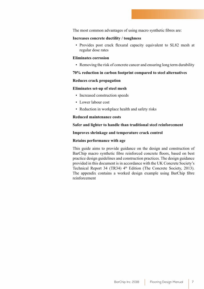
Themostcommonadvantagesofusingmacrosyntheticfibresare:
Increases concrete ductility / toughness
• Provides post crack flexural capacity equivalent to SL82 mesh atregular dose rates
Eliminates corrosion
• Removing the risk of concrete cancer and ensuring long term durability
70% reduction in carbon footprint compared to steel alternatives
Reduces crack propagation
Eliminates set-up of steel mesh
• Increased construction speeds
• Lower labour cost
• Reduction in workplace health and safety risks
Reduced maintenance costs
Safer and lighter to handle than traditional steel reinforcement
Improves shrinkage and temperature crack control
Retains performance with age
This guide aims to provide guidance on the design and construction of BarChipmacro syntheticfibre reinforced concretefloors, basedonbestpractice design guidelines and construction practices. The design guidance provided in this document is in accordance with the UK Concrete Society’s Technical Report 34 (TR34) 4th Edition (The Concrete Society, 2013). The appendix contains a worked design example using BarChip fibrereinforcement
Flooring Design ManualBarChip Inc. 2018 7
2. Synthetic Fibres in Concrete
TheintroductionofhighperformancemacrosyntheticfibresbyBarChipmade of virgin polypropylene (BarChip range) or polymer bi-components (MQ58) with a tensile strength of over 600 MPa has shared the attention of steel fibres as concrete reinforcement in non-free standing structuralelements. Macro synthetic fibres are non-corrosive in nature, whichenhances concrete durability. This is exemplified through their use inmarine works to “eliminate corrosion risk under exposure to seawater” (Bernard,2004).BarChipmacrosyntheticfibreisenvironmentallyfriendlyand drastically reduces the carbon footprint of concrete reinforcement.
2.1 General
Like steel fibres, high performance macro synthetic fibres improveconcrete’s post cracking behaviour, such as toughness, ductility and residual strength.
• “Theabilityofsteelandsyntheticfibrestoabsorbenergyhaslongbeenrecognizedasoneofthemostimportantbenefitsofincorporatingfibresintoplainconcrete…”(GopalaratnamandGettu,1995)
• Fibreconcreteperformanceis“controlledbythevolumeoffibres,thephysicalpropertiesoffibresandthematrix,andthebondbetweenthe two” (The Concrete Society, 2007)
• Ductilityisacharacteristicdependentonfibretype,tensilestrength,and anchorage mechanism (Soutsos et al., 2012).
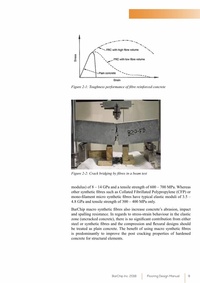
Oneof thecommonfibreconcrete strength indicators is themeasureoftoughness,whichcanbedefinedasenergyabsorptionor theareaundertheloaddeflectioncurve.Theloaddeflection(orstress/strain)curveofabending test illustrates the way in which this is measured. What is notable, is that thefibres substantially increase the abilityof concrete to sustainload at deflections or strains beyond the appearance of first crack.Thedecrease in flexural resistancewith the increase in deflection is knownas‘strainsoftening’.Thisbehaviourisdifferentfromthetraditionalsteelreinforcedconcretewherethedesignaimsatincreasingflexuralresistanceaftertheconcretecracks(‘strainhardening’or‘tensionstiffening’).
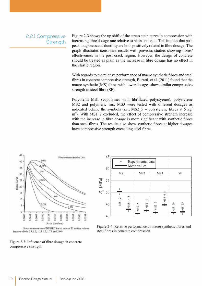
When the concrete cracks in the tension zone under flexural stress, thefibresintheconcretematrixcreatea‘bridging’effectatthecrackedregion,whichcontinuetoholdtheconcretetogetheruntilfibrepulloutoccurs.Thepulloutoffibresonlyoccursifthefibresaresufficientlystiff;otherwise,thefibresmightrupturebeforefibrepulloutandfailurecanbebrittleandcatastrophic.Itisthefibrepulloutorde-bondingthatallowsfibreconcreteto be ‘ductile’.
BarChip fibres are high performance macro synthetic fibres that areengineered for structural performance, having an elastic modulus (Young’s
2.2 Strength Performance
Flooring Design Manual BarChip Inc. 20188
modulus) of 8 – 14 GPa and a tensile strength of 600 – 700 MPa. Whereas othersyntheticfibressuchasCollatedFibrillatedPolypropylene(CFP)ormono-filamentmicrosyntheticfibreshavetypicalelasticmoduliof3.5–4.8 GPa and tensile strength of 300 – 400 MPa only.
BarChipmacrosyntheticfibresalsoincreaseconcrete’sabrasion,impactand spalling resistance. In regards to stress-strain behaviour in the elastic zone(uncrackedconcrete),thereisnosignificantcontributionfromeithersteelorsyntheticfibresandthecompressionandflexuraldesignsshouldbe treatedasplainconcrete.Thebenefitofusingmacrosyntheticfibresis predominantly to improve the post cracking properties of hardened concrete for structural elements.
Figure 2-1: Toughness performance of fibre reinforced concrete
Figure 2-2: Crack bridging by fibres in a beam test
Flooring Design ManualBarChip Inc. 2018 9
2.2.1 Compressive Strength
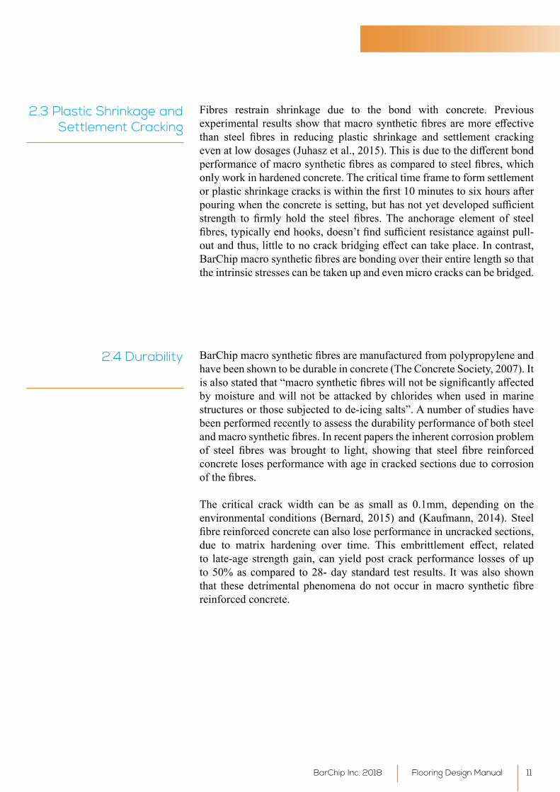
Figure 2-3 shows the up shift of the stress stain curve in compression with increasingfibredosageraterelativetoplainconcrete.Thisimpliesthatpostpeaktoughnessandductilityarebothpositivelyrelatedtofibredosage.Thegraph illustrates consistent resultswithprevious studies showingfibres’effectiveness in the post crack region.However, the design of concreteshouldbetreatedasplainastheincreaseinfibredosagehasnoeffectinthe elastic region.
Withregardstotherelativeperformanceofmacrosyntheticfibresandsteelfibresinconcretecompressivestrength,Buratti,etal.(2011)foundthatthemacrosynthetic(MS)fibreswithlowerdosagesshowsimilarcompressivestrengthtosteelfibre(SF).
Polyolefin MS1 (copolymer with fibrillated polystyrene), polystyreneMS2 and polymeric mix MS3 were tested with different dosages asindicatedbehind thesymbols (i.e.,MS2_5=polystyrenefibresat5kg/m3).WithMS1_2 excluded, the effect of compressive strength increasewiththeincreaseinfibredosageismoresignificantwithsyntheticfibresthansteelfibres.Theresultsalsoshowsyntheticfibresathigherdosageshavecompressivestrengthexceedingsteelfibres.
Figure2-3:Influenceoffibredosageinconcretecompressive strength.
Figure2-4:Relativeperformanceofmacrosyntheticfibresandsteelfibresinconcretecompression.
Flooring Design Manual BarChip Inc. 201810
2.3 Plastic Shrinkage and Settlement Cracking
Fibres restrain shrinkage due to the bond with concrete. Previous experimentalresultsshowthatmacrosyntheticfibresaremoreeffectivethan steel fibres in reducing plastic shrinkage and settlement crackingevenatlowdosages(Juhaszetal.,2015).Thisisduetothedifferentbondperformanceofmacrosyntheticfibresascomparedtosteelfibres,whichonly work in hardened concrete. The critical time frame to form settlement orplasticshrinkagecracksiswithinthefirst10minutestosixhoursafterpouringwhentheconcreteissetting,buthasnotyetdevelopedsufficientstrength to firmly hold the steel fibres.The anchorage element of steelfibres,typicallyendhooks,doesn’tfindsufficientresistanceagainstpull-outandthus,littletonocrackbridgingeffectcantakeplace.Incontrast,BarChipmacrosyntheticfibresarebondingovertheirentirelengthsothatthe intrinsic stresses can be taken up and even micro cracks can be bridged.
2.4 Durability BarChipmacrosyntheticfibresaremanufacturedfrompolypropyleneandhave been shown to be durable in concrete (The Concrete Society, 2007). It isalsostatedthat“macrosyntheticfibreswillnotbesignificantlyaffectedby moisture and will not be attacked by chlorides when used in marine structures or those subjected to de-icing salts”. A number of studies have been performed recently to assess the durability performance of both steel andmacrosyntheticfibres.Inrecentpaperstheinherentcorrosionproblemof steel fibres was brought to light, showing that steel fibre reinforcedconcrete loses performance with age in cracked sections due to corrosion ofthefibres. The critical crack width can be as small as 0.1mm, depending on the environmental conditions (Bernard, 2015) and (Kaufmann, 2014). Steel fibrereinforcedconcretecanalsoloseperformanceinuncrackedsections,due to matrix hardening over time. This embrittlement effect, relatedto late-age strength gain, can yield post crack performance losses of up to 50% as compared to 28- day standard test results. It was also shown that thesedetrimentalphenomenadonotoccur inmacro syntheticfibrereinforced concrete.
Flooring Design ManualBarChip Inc. 2018 11
2.5 Concrete Mix Theimportantparametersthataffectworkabilityofmacrosyntheticfibrereinforced concrete are:
• Thefibrelength
• Fibrefineness
• Fibre content
• The aggregate content
• Aggregate size and grading and
• Water to cementitious ratio in the mix.
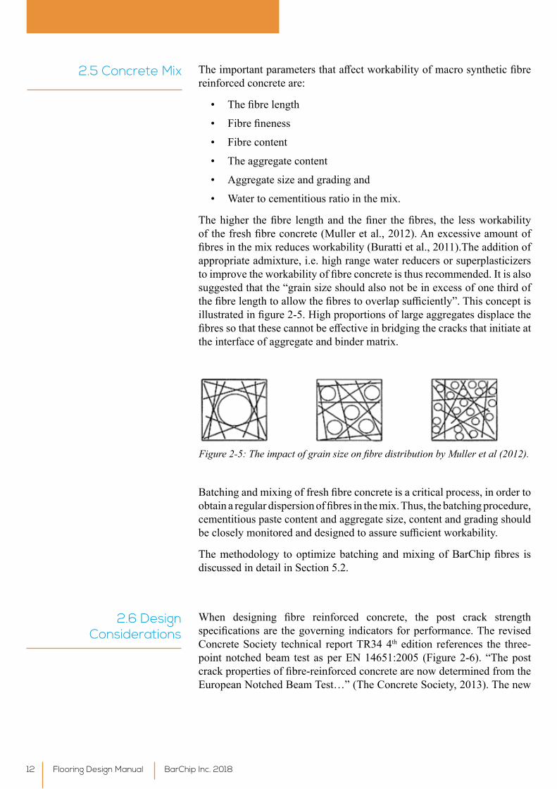
Thehigher thefibre lengthand thefiner thefibres, the lessworkabilityofthefreshfibreconcrete(Mulleretal.,2012).Anexcessiveamountoffibresinthemixreducesworkability(Burattietal.,2011).Theadditionofappropriate admixture, i.e. high range water reducers or superplasticizers toimprovetheworkabilityoffibreconcreteisthusrecommended.Itisalsosuggested that the “grain size should also not be in excess of one third of thefibrelengthtoallowthefibrestooverlapsufficiently”.Thisconceptisillustratedinfigure2-5.Highproportionsoflargeaggregatesdisplacethefibressothatthesecannotbeeffectiveinbridgingthecracksthatinitiateatthe interface of aggregate and binder matrix.
Figure 2-5: The impact of grain size on fibre distribution by Muller et al (2012).
Batchingandmixingoffreshfibreconcreteisacriticalprocess,inordertoobtainaregulardispersionoffibresinthemix.Thus,thebatchingprocedure,cementitious paste content and aggregate size, content and grading should becloselymonitoredanddesignedtoassuresufficientworkability.
Themethodology tooptimizebatchingandmixingofBarChipfibres isdiscussed in detail in Section 5.2.
2.6 Design Considerations
When designing fibre reinforced concrete, the post crack strengthspecificationsare thegoverning indicators forperformance.TherevisedConcrete Society technical report TR34 4th edition references the three-point notched beam test as per EN 14651:2005 (Figure 2-6). “The post crackpropertiesoffibre-reinforcedconcretearenowdeterminedfromtheEuropeanNotchedBeamTest…”(TheConcreteSociety,2013).Thenew
Flooring Design Manual BarChip Inc. 201812
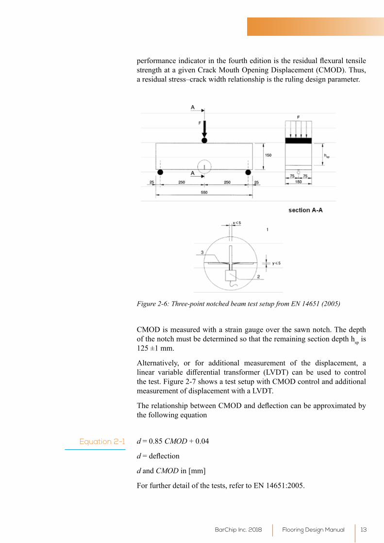
performanceindicatorinthefourtheditionistheresidualflexuraltensilestrength at a given Crack Mouth Opening Displacement (CMOD). Thus, a residual stress–crack width relationship is the ruling design parameter.
Figure 2-6: Three-point notched beam test setup from EN 14651 (2005)
CMOD is measured with a strain gauge over the sawn notch. The depth of the notch must be determined so that the remaining section depth hsp is 125 ±1 mm.
Alternatively, or for additional measurement of the displacement, a linear variable differential transformer (LVDT) can be used to controlthe test. Figure 2-7 shows a test setup with CMOD control and additional measurementofdisplacementwithaLVDT.
TherelationshipbetweenCMODanddeflectioncanbeapproximatedbythe following equation
d = 0.85 CMOD + 0.04
d=deflection
d and CMOD in [mm]
For further detail of the tests, refer to EN 14651:2005.
Equation 2-1
Flooring Design ManualBarChip Inc. 2018 13
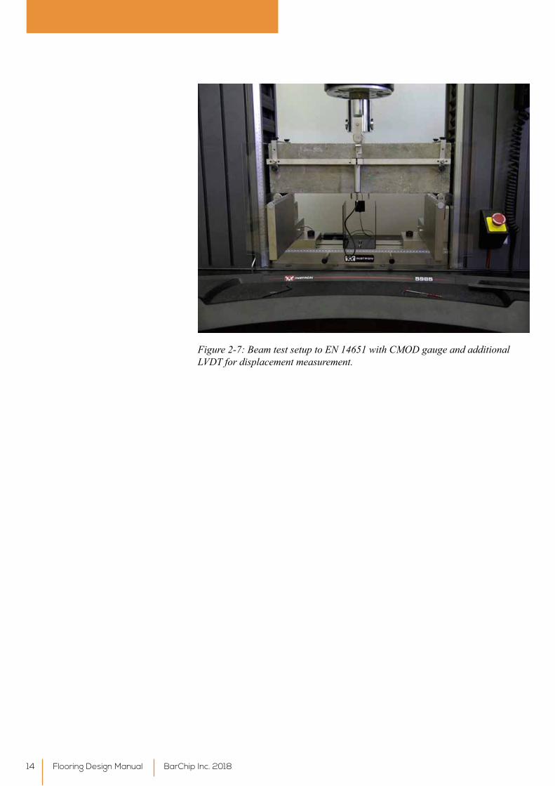
Figure 2-7: Beam test setup to EN 14651 with CMOD gauge and additional LVDT for displacement measurement.
Flooring Design Manual BarChip Inc. 201814
3. Synthetic Fibres Properties
3.1 General Fibres are regulated by the European harmonized set of Standards. Polymer fibresareclassifiedinEN14889-2:2006.Polymerfibresaredividedintotwo main classes according to their physical form:
Class1:Microfibres:
• Class1a:Microfibres<0.3mmindiameter,mono-filamented
• Class1b:Microfibres<0.3mmindiameter,fibrillated
Application: plastic shrinkage control, impact protection, anti-spalling and fireresistance.
Class2:Macrofibres>0.3mmindiameter
Application: structural reinforcement in concrete where an increase in residualflexuralstrengthisrequired.
3.2 Macro Synthetic Fibres - BarChip
BarChipmacro synthetic fibres are engineered polymer fibres used forstructural reinforcement as well as for crack control. BarChip fibresare certified to CE for “structural use in concrete, mortar or grout”under the requirements of EN 14889-2:2006 (European Committee for Standardisation (CEN), 2006). Further, BarChip fibres complywithASTMC1116-03,StandardSpecificationsforFibreReinforcedConcreteand Shotcrete, Type 3 (American Society for Testing and Materials, 2010).
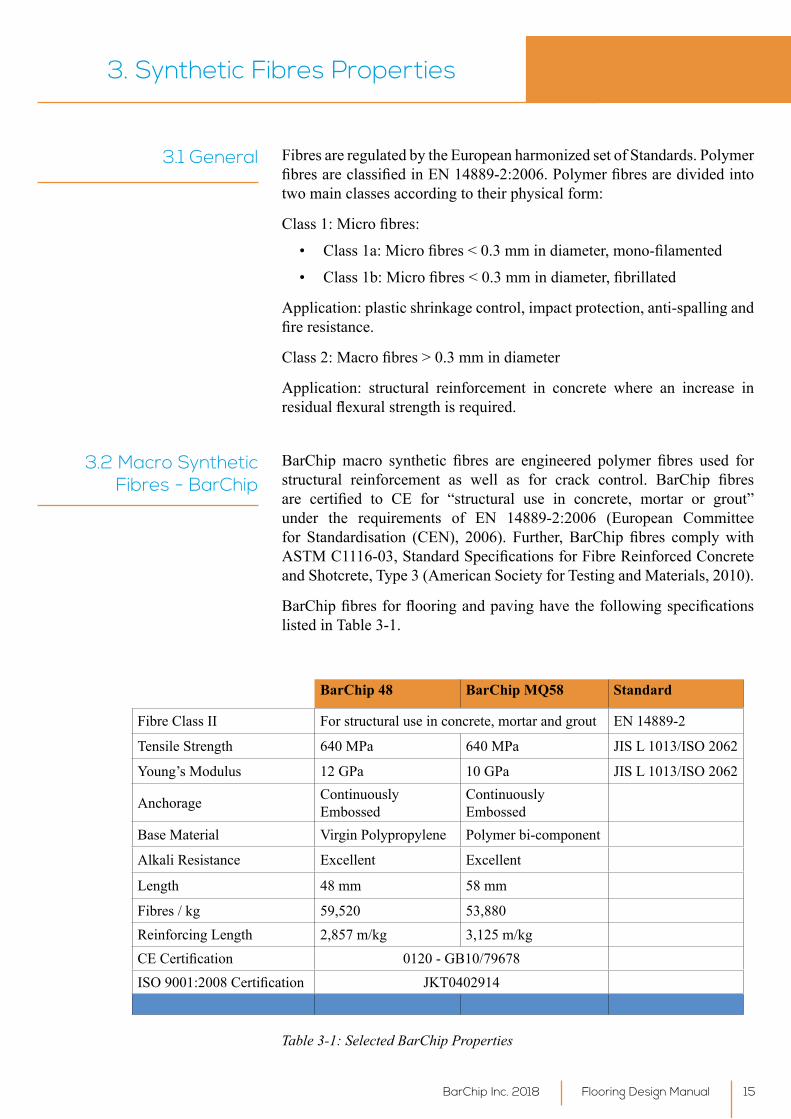
BarChipfibresforflooringandpavinghavethefollowingspecificationslisted in Table 3-1.
BarChip 48 BarChip MQ58 Standard
Fibre Class II For structural use in concrete, mortar and grout EN 14889-2
Tensile Strength 640 MPa 640 MPa JIS L 1013/ISO 2062
Young’s Modulus 12 GPa 10 GPa JIS L 1013/ISO 2062
Anchorage Continuously Embossed
Continuously Embossed
Base Material VirginPolypropylene Polymer bi-component
Alkali Resistance Excellent Excellent
Length 48 mm 58 mm
Fibres / kg 59,520 53,880 Reinforcing Length 2,857 m/kg 3,125 m/kgCECertification 0120 - GB10/79678ISO9001:2008Certification JKT0402914
Table 3-1: Selected BarChip Properties
Flooring Design ManualBarChip Inc. 2018 15

ThecharacteristicsofBarChipfibreare:
• Can be used to replace steel mesh and welded wire reinforcement
• Donotleave‘hairy’finishontheconcrete
• Donotnegativelyaffectfinishingtechniques
• Do not damage pumping or placing equipment
• Do not greatly reduce concrete slump
There is awide range of differentBarChipfibres of different structuralperformancefordifferentapplications.Eachfibretypehasitssize,bondandanchorageconfigurationthataffectthecompositestrengthandtoughnessperformance differently from others. BarChip MQ58 was specificallydevelopedforindustrialfloorsandpavements.Thisfibredoesnotprovidethe same level of structural performance as compared to BC48, but excels withanoutstandingfinishingability,whichisoneoftheparamountcriteriainflooring.
Pleaseconsultourtechnicalserviceforthemostappropriatefibreforyourapplication.
Flooring Design Manual BarChip Inc. 201816
4. Design of Ground Supported Slabs using BarChip Fibre Reinforcement
4.1 General This section illustrates the design steps for ground supported concrete slabsusingBarChipmacrosyntheticfibres.Thedesignassumestheslabisfully supported on undisturbed ground and/or subbase and that there is no access below the slab for its intended structural life.
The twopossible failuremodes for ground supported slabs areflexuraland punching shear. In order to avoid potential punching and potential slab curling TR34 4th edition recommends that the minimum design thickness for ground supported slab is 150 mm. This minimum thickness is chosen in order to minimise the curling and warping of slabs, which can occurduetomoistureandtemperaturedifferentialsbetweenthetopandbottom surfaces of the slabs. By ensuring an adequate dead load through this minimum thickness requirement the risk of curling and warping is significantlyreduced.
ThegeneraldesignprincipalofgroundsupportedslabsinflexureisbasedontheYieldLineTheory,usingtheductilityprovidedbyfibrereinforcementtoachieve plastic behaviour after cracking. Partial safety factors are required at the ultimate limit state (ULS) design to control the surface cracks at the hogging (negative moment) region and residual post crack value at the sagging (positive moment) region. The design of punching shear is based on the approach in Eurocode 2 for suspended slabs with allowance for loads to be transferred directly through the slab to the ground.
4.2 Partial Safety Factors
The partial safety factors used in ground supported floors are listed intables 4-1 and 4-2.
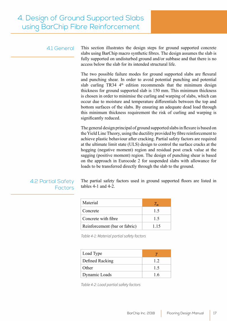
Material γm
Concrete 1.5
Concretewithfibre 1.5Reinforcement (bar or fabric) 1.15
Table 4-1: Material partial safety factors
Load Type γDefinedRacking 1.2Other 1.5Dynamic Loads 1.6
Table 4-2: Load partial safety factors
Flooring Design ManualBarChip Inc. 2018 17
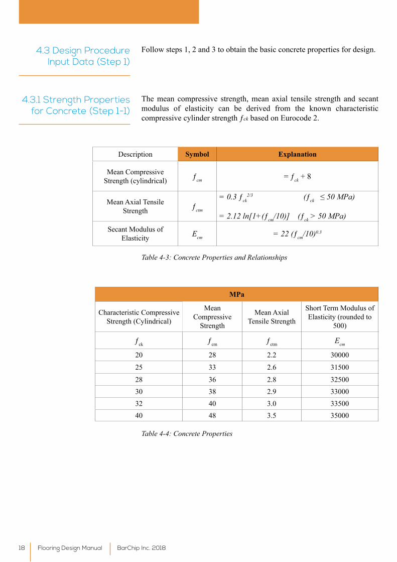
Follow steps 1, 2 and 3 to obtain the basic concrete properties for design.4.3 Design Procedure Input Data (Step 1)
The mean compressive strength, mean axial tensile strength and secant modulus of elasticity can be derived from the known characteristic compressive cylinder strength ƒck based on Eurocode 2.
4.3.1 Strength Properties for Concrete (Step 1-1)
Description Symbol Explanation
Mean Compressive Strength (cylindrical) ƒcm = ƒck + 8
Mean Axial Tensile Strength ƒctm
= 0.3 ƒck2/3 (ƒck ≤ 50 MPa)
= 2.12 ln[1+(ƒcm/10)] (ƒck > 50 MPa)Secant Modulus of
Elasticity Ecm = 22 (ƒcm/10)0.3
Table 4-3: Concrete Properties and Relationships
MPa
Characteristic Compressive Strength (Cylindrical)
Mean Compressive
Strength
Mean Axial Tensile Strength
Short Term Modulus of Elasticity (rounded to
500)
ƒck ƒcm ƒctm Ecm
20 28 2.2 30000
25 33 2.6 31500
28 36 2.8 3250030 38 2.9 3300032 40 3.0 3350040 48 3.5 35000
Table 4-4: Concrete Properties
Flooring Design Manual BarChip Inc. 201818
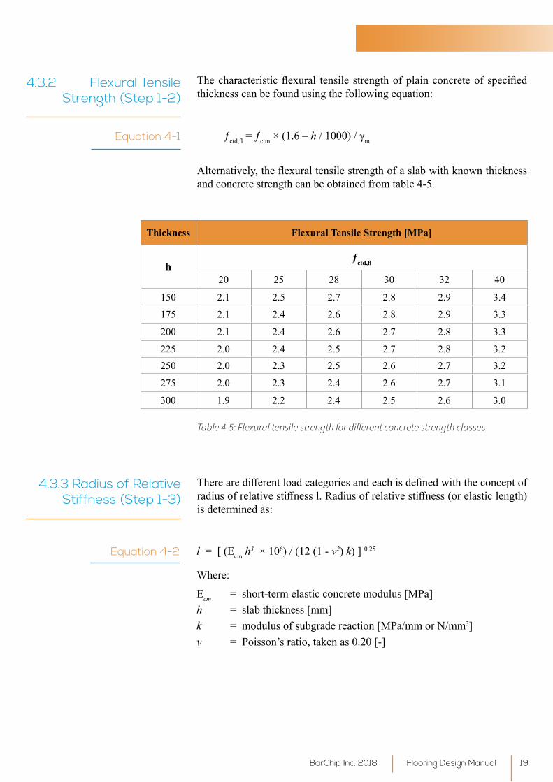
4.3.2 Flexural Tensile Strength (Step 1-2)
Thecharacteristicflexural tensile strengthofplainconcreteof specifiedthickness can be found using the following equation:
ƒctd,fl = ƒctm × (1.6 – h/1000)/γmEquation 4-1
Alternatively,theflexuraltensilestrengthofaslabwithknownthicknessand concrete strength can be obtained from table 4-5.
Table 4-5: Flexural tensile strength for different concrete strength classes
Thickness Flexural Tensile Strength [MPa]
hƒctd,fl
20 25 28 30 32 40
150 2.1 2.5 2.7 2.8 2.9 3.4
175 2.1 2.4 2.6 2.8 2.9 3.3
200 2.1 2.4 2.6 2.7 2.8 3.3
225 2.0 2.4 2.5 2.7 2.8 3.2250 2.0 2.3 2.5 2.6 2.7 3.2
275 2.0 2.3 2.4 2.6 2.7 3.1
300 1.9 2.2 2.4 2.5 2.6 3.0
4.3.3 Radius of Relative Stiffness (Step 1-3)
Therearedifferentloadcategoriesandeachisdefinedwiththeconceptofradiusofrelativestiffnessl.Radiusofrelativestiffness(orelasticlength)is determined as:
Equation 4-2 l = [ (Ecm h3 × 106) / (12 (1 - ν2) k) ] 0.25
Where:
Ecm = short-term elastic concrete modulus [MPa]h = slab thickness [mm]k = modulus of subgrade reaction [MPa/mm or N/mm3]ν = Poisson’s ratio, taken as 0.20 [-]
Flooring Design ManualBarChip Inc. 2018 19
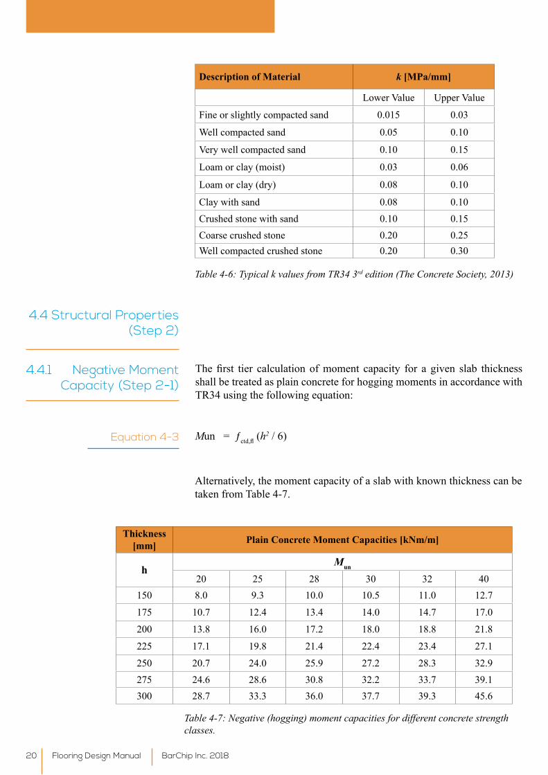
Description of Material k [MPa/mm]
LowerValue UpperValue
Fine or slightly compacted sand 0.015 0.03
Well compacted sand 0.05 0.10
Verywellcompactedsand 0.10 0.15
Loam or clay (moist) 0.03 0.06
Loam or clay (dry) 0.08 0.10
Clay with sand 0.08 0.10Crushed stone with sand 0.10 0.15Coarse crushed stone 0.20 0.25Well compacted crushed stone 0.20 0.30
Table 4-6: Typical k values from TR34 3rd edition (The Concrete Society, 2013)
4.4 Structural Properties (Step 2)
4.4.1 Negative Moment Capacity (Step 2-1)
Thefirst tier calculationofmoment capacity for a given slab thicknessshall be treated as plain concrete for hogging moments in accordance with TR34 using the following equation:
Equation 4-3 Mun = ƒctd,fl (h2 / 6)
Alternatively, the moment capacity of a slab with known thickness can be taken from Table 4-7.
Thickness [mm] Plain Concrete Moment Capacities [kNm/m]
hMun
20 25 28 30 32 40150 8.0 9.3 10.0 10.5 11.0 12.7
175 10.7 12.4 13.4 14.0 14.7 17.0
200 13.8 16.0 17.2 18.0 18.8 21.8
225 17.1 19.8 21.4 22.4 23.4 27.1
250 20.7 24.0 25.9 27.2 28.3 32.9275 24.6 28.6 30.8 32.2 33.7 39.1300 28.7 33.3 36.0 37.7 39.3 45.6
Table 4-7: Negative (hogging) moment capacities for different concrete strength classes.
Flooring Design Manual BarChip Inc. 201820
4.4.2 Positive Moment Capacity with Macro Synthetic Fibre Reinforced Concrete (Step 2- 2)
4.4.2.1 Determining Fibre Reinforced Concrete
Properties
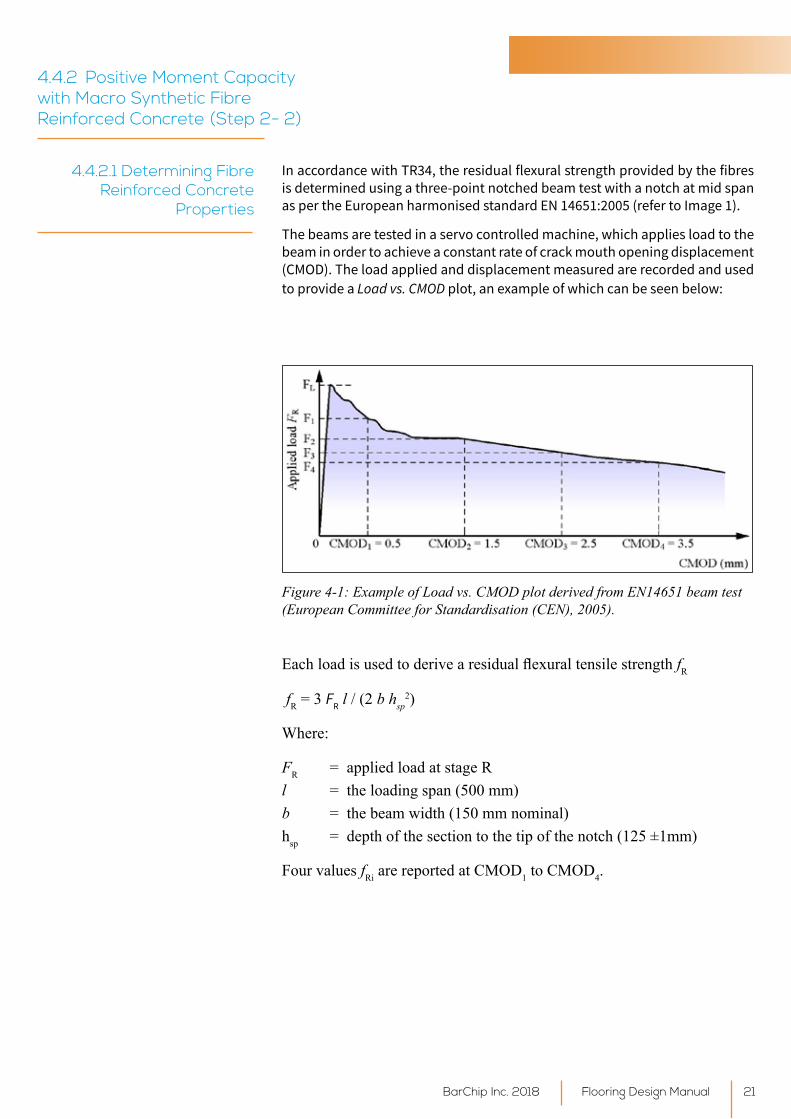
In accordance with TR34, the residual flexural strength provided by the fibres is determined using a three-point notched beam test with a notch at mid span as per the European harmonised standard EN 14651:2005 (refer to Image 1).
The beams are tested in a servo controlled machine, which applies load to the beam in order to achieve a constant rate of crack mouth opening displacement (CMOD). The load applied and displacement measured are recorded and used to provide a Load vs. CMOD plot, an example of which can be seen below:
Figure 4-1: Example of Load vs. CMOD plot derived from EN14651 beam test (European Committee for Standardisation (CEN), 2005).
EachloadisusedtoderivearesidualflexuraltensilestrengthfR
Flooring Design ManualBarChip Inc. 2018 21
fR = 3 FR l / (2 b hsp2)
Where:
FR = applied load at stage Rl = the loading span (500 mm)b = the beam width (150 mm nominal)hsp = depth of the section to the tip of the notch (125 ±1mm)
Four values fRi are reported at CMOD1 to CMOD4.
4.4.2.2 Calculation of Residual Moment Capacity from Notched Beam Tests
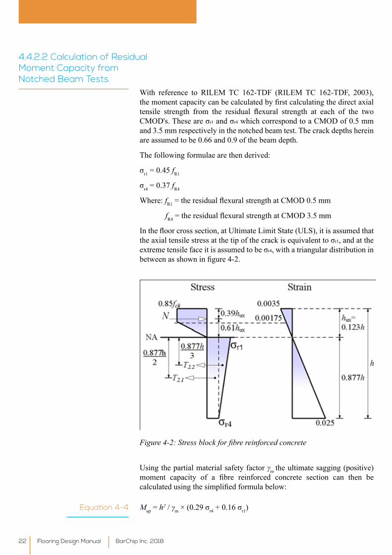
With reference to RILEM TC 162-TDF (RILEM TC 162-TDF, 2003), themomentcapacitycanbecalculatedbyfirstcalculatingthedirectaxialtensile strength from the residual flexural strength at each of the twoCMOD's.Theseareσr1andσr4 which correspond to a CMOD of 0.5 mm and 3.5 mm respectively in the notched beam test. The crack depths herein are assumed to be 0.66 and 0.9 of the beam depth.
The following formulae are then derived:
σr1 = 0.45 fR1
σr4 = 0.37 fR4
Where: fR1=theresidualflexuralstrengthatCMOD0.5mm
fR4=theresidualflexuralstrengthatCMOD3.5mm
Inthefloorcrosssection,atUltimateLimitState(ULS),itisassumedthattheaxialtensilestressatthetipofthecrackisequivalenttoσr1, and at the extremetensilefaceitisassumedtobeσr4, with a triangular distribution in betweenasshowninfigure4-2.
Figure 4-2: Stress block for fibre reinforced concrete
Using the partial material safety factor γm the ultimate sagging (positive) moment capacity of a fibre reinforced concrete section can then becalculatedusingthesimplifiedformulabelow:
Mup = h2 / γm×(0.29σr4+0.16σr1)Equation 4-4
Flooring Design Manual BarChip Inc. 201822
4.5 Select Design Loads (Step 3)
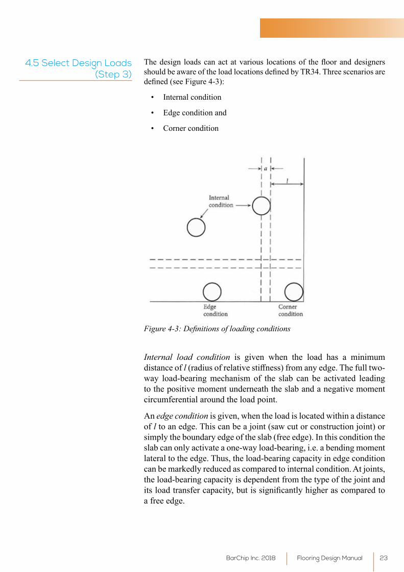
Thedesign loadscanactatvarious locationsof theflooranddesignersshouldbeawareoftheloadlocationsdefinedbyTR34.Threescenariosaredefined(seeFigure4-3):
• Internal condition
• Edge condition and
• Corner condition
Figure 4-3: Definitions of loading conditions
Internal load condition is given when the load has a minimum distance of l(radiusofrelativestiffness)fromanyedge.Thefulltwo-way load-bearing mechanism of the slab can be activated leading to the positive moment underneath the slab and a negative moment circumferential around the load point.
An edge condition is given, when the load is located within a distance of l to an edge. This can be a joint (saw cut or construction joint) or simply the boundary edge of the slab (free edge). In this condition the slab can only activate a one-way load-bearing, i.e. a bending moment lateral to the edge. Thus, the load-bearing capacity in edge condition can be markedly reduced as compared to internal condition. At joints, the load-bearing capacity is dependent from the type of the joint and itsloadtransfercapacity,butissignificantlyhigherascomparedtoa free edge.
Flooring Design ManualBarChip Inc. 2018 23
An entirely different load-bearing behaviour is given when the load islocated in corner condition, especially when the corner marks the boundary corner of the slab. In this case, the corner will be bent down, creating a hogging (negative) bending moment diagonally across the edges. The loadbearingcapacitywillbesignificantly reducedcompared to internalcondition. At joints, the load- bearing capacity is dependent from the type of the joint and its load transfer capacity, but is significantly higher ascompared to a free corner.
4.5.1 Single Point Load (Step 3-1)
The positive bending moment induced by a single point load is radial and has its maximum directly under the load. The point of counter-flexure(zero bending moment) is located approximately at radial distance of 1.0 l (where l=radiusofrelativestiffness)fromtheload.Themaximumnegative circumferential moment is at an approximate radial distance of 2.0 l from the load. The moment approaches zero at an approximate radial distance of 3.0 l from the load.
Todeterminethecharacteristicofasinglepointloadasdefinedbytheratioof a/l where:
equivalent radius of the contact area of the load (in mm2) based on the effective contact area.Refer tomanufacturer’s information forspecific contact area (e.g.wheels or base plates from rack feet ormezzaninecolumns).Theeffectivedimensionofthebaseplateshallbe taken as d + 4t, then rearrange for the equivalent radius r where:
a =
πr2 = (d + 4t)2
√ [(d + 4t)2 / π]r =
t = thickness of the base plate [mm]d = width of the racking leg/column [mm]
Itissometimesdifficulttofindexactingdimensionsofthebaseplates.Intheabsenceofproject-specificdetails,aneffectivedimensionof100mmx 100 mm should be used.
A single point load such as:
• Racking leg or mezzanine column
Shall satisfy the following condition:
P*≤Pu
The point load can act at various locations on the slab and the locations are dividedintothreemaincategories;internal load, edge load and corner load.
Flooring Design Manual BarChip Inc. 201824
For internal load with:
a/l = 0: Pu,0=2π(Mp + Mn)
a/l≥0.2: Pu,0.2=4π(Mp + Mn)/ [ 1 – (a / 3l)]
For free edge load with:
a/l = 0: Pu,0=[π(Mp + Mn) / 2] + 2Mn
a/l≥0.2: Pu,0.2=[π(Mp + Mn) + 4Mn] / [1 – (2a / 3l)]
For free corner load with:
a/l = 0: Pu,0 = 2Mn
a/l≥0.2: Pu,0.2 = 4Mn / [1 – (a / l)]
Interpolate for values of a/l between 0 and 0.2.
Equation 4-5
Equation 4-6
Equation 4-7
Equation 4-8
Equation 4-9
Equation 4-10
4.5.2 Dual Point Load (Step 3-2)
This section applies to two point loads with centre line spacing ‘x’ more than twice theslab thickness(2h). Ifx≤2h, theyshallbe treatedasanaggregate single point load, acting on the combined area. The dual loads are to be treated as two single point loads when they are centre spaced more than x > 2h.
Multiple point loads such as:
• Truck wheel loads
• Multiple racking loads (back to back)
Shall satisfy the following condition:
P*≤Pu
For internal load with:
a/l = 0: Pu,0=[2π+(1.8x/l)] × [Mp + Mn]
a/l≥0.2:Pu,0.2=[4π/(1-(a/3l) + 1.8x / (l - (a / 2))] × [Mp + Mn]
Equation 4-11
Equation 4-12
Flooring Design ManualBarChip Inc. 2018 25
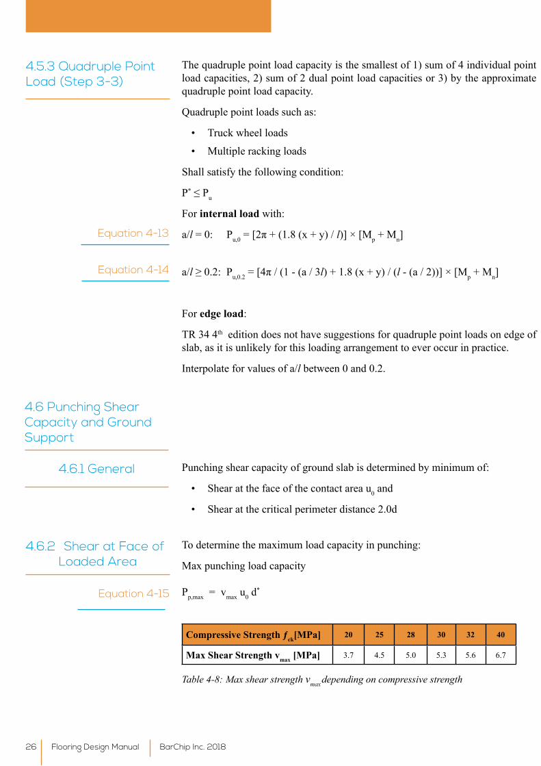
4.5.3 Quadruple Point Load (Step 3-3)
The quadruple point load capacity is the smallest of 1) sum of 4 individual point load capacities, 2) sum of 2 dual point load capacities or 3) by the approximate quadruple point load capacity.
Quadruple point loads such as:
• Truck wheel loads
• Multiple racking loads
Shall satisfy the following condition:
P*≤Pu
For internal load with:
a/l = 0: Pu,0=[2π+(1.8(x+y)/l)] × [Mp + Mn]
a/l≥0.2:Pu,0.2=[4π/(1-(a/3l) + 1.8 (x + y) / (l - (a / 2))] × [Mp + Mn]
For edge load:
TR 34 4th edition does not have suggestions for quadruple point loads on edge of slab, as it is unlikely for this loading arrangement to ever occur in practice.
Interpolate for values of a/l between 0 and 0.2.
Equation 4-13
Equation 4-14
4.6 Punching Shear Capacity and Ground Support
Punching shear capacity of ground slab is determined by minimum of:
• Shear at the face of the contact area u0 and
• Shear at the critical perimeter distance 2.0d
4.6.1 General
4.6.2 Shear at Face of Loaded Area
To determine the maximum load capacity in punching:
Max punching load capacity
Pp,max = vmax u0 d*Equation 4-15
Compressive Strength ƒck[MPa] 20 25 28 30 32 40
Max Shear Strength vmax [MPa] 3.7 4.5 5.0 5.3 5.6 6.7
Table 4-8: Max shear strength vmax depending on compressive strength
Flooring Design Manual BarChip Inc. 201826
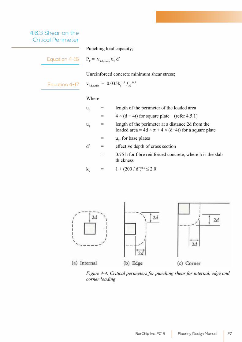
4.6.3 Shear on the Critical Perimeter
Punchingloadcapacity;
PP = vRd,c,min u1 d*
Unreinforcedconcreteminimumshearstress;
vRd,c,min = 0.035ks1.5 ƒck
0.5
Where:
u0 = length of the perimeter of the loaded area
= 4 × (d + 4t) for square plate (refer 4.5.1)
u1 = length of the perimeter at a distance 2d from the loadedarea=4d×π+4×(d+4t)forasquareplate
= u0, for base plates
d* = effectivedepthofcrosssection
= 0.75hforfibrereinforcedconcrete,wherehistheslab thickness
ks = 1 + (200 / d*)0.5≤2.0
Equation 4-16
Equation 4-17
Figure 4-4: Critical perimeters for punching shear for internal, edge and corner loading
Flooring Design ManualBarChip Inc. 2018 27

vRd,c,min [MPa]
Concrete Compressive Strength ƒck [MPa]
Slab Depth h [mm] 20 25 28 30 32 40150 - 250 0.44 0.50 0.52 0.54 0.56 0.63
275 0.44 0.49 0.52 0.54 0.55 0.62300 0.42 0.47 0.50 0.52 0.54 0.60
Table 4-9: Unreinforced concrete minimum shear strength
TR34 4th edition states that ‘there are no data available to demonstrate thatshearcapacityenhancementisprovidedbymacro-syntheticfibresandtherefore no enhancement should be assumed, and the calculation is made using plain concrete parameters for punching shear capacity in macro syntheticfibrereinforcedsections.
Flooring Design Manual BarChip Inc. 201828
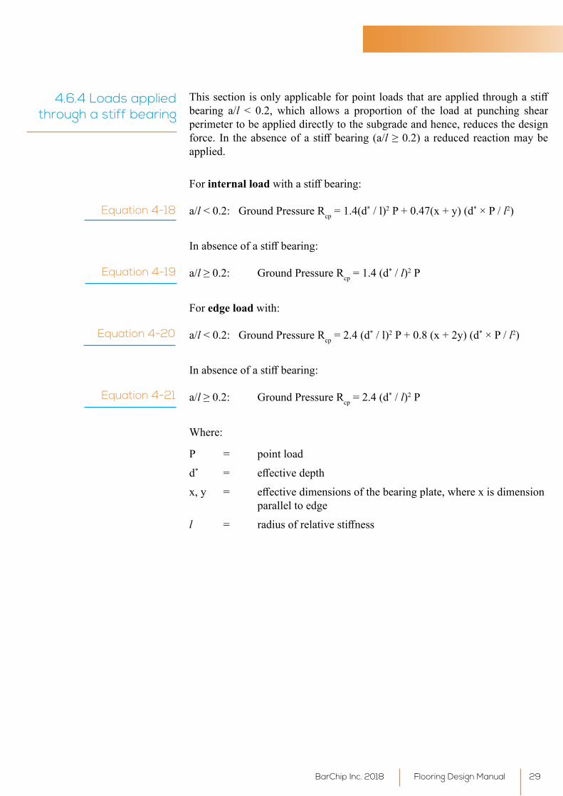
4.6.4 Loads applied through a stiff bearing
Thissectionisonlyapplicableforpointloadsthatareappliedthroughastiffbearing a/l < 0.2, which allows a proportion of the load at punching shearperimeter to be applied directly to the subgrade and hence, reduces the design force. In theabsenceofastiffbearing(a/l≥0.2)a reducedreactionmaybeapplied.
For internal loadwithastiffbearing:
a/l<0.2:GroundPressureRcp = 1.4(d* / l)2 P + 0.47(x + y) (d* × P / l2)
Inabsenceofastiffbearing:
a/l≥0.2: GroundPressureRcp = 1.4 (d* / l)2 P
For edge load with:
a/l<0.2:GroundPressureRcp = 2.4 (d* / l)2 P + 0.8 (x + 2y) (d* × P / l2)
Inabsenceofastiffbearing:
a/l≥0.2: GroundPressureRcp = 2.4 (d* / l)2 P
Where:
P = point load
d* = effectivedepth
x,y = effectivedimensionsofthebearingplate,wherexisdimension parallel to edge
l = radiusofrelativestiffness
Equation 4-18
Equation 4-19
Equation 4-20
Equation 4-21
Flooring Design ManualBarChip Inc. 2018 29
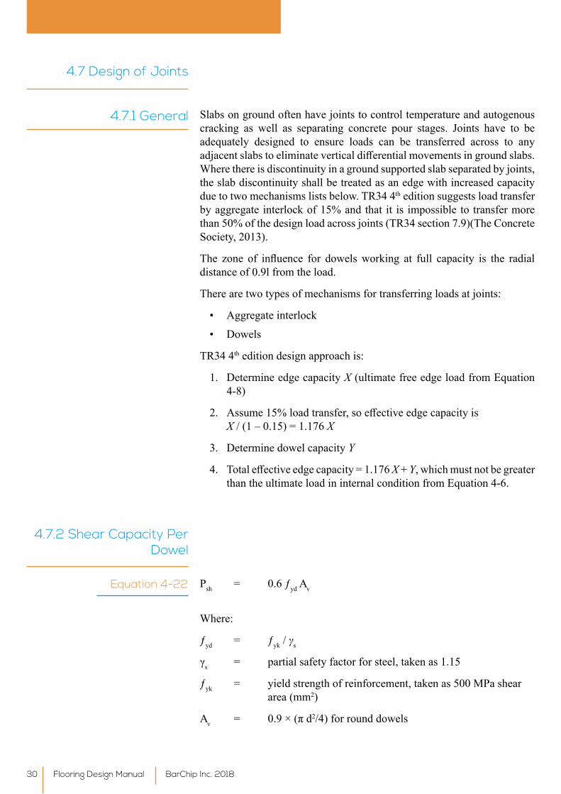
4.7 Design of Joints
Slabs on ground often have joints to control temperature and autogenous cracking as well as separating concrete pour stages. Joints have to be adequately designed to ensure loads can be transferred across to any adjacentslabstoeliminateverticaldifferentialmovementsingroundslabs.Where there is discontinuity in a ground supported slab separated by joints, the slab discontinuity shall be treated as an edge with increased capacity due to two mechanisms lists below. TR34 4th edition suggests load transfer by aggregate interlock of 15% and that it is impossible to transfer more than 50% of the design load across joints (TR34 section 7.9)(The Concrete Society, 2013).
The zone of influence for dowelsworking at full capacity is the radialdistance of 0.9l from the load.
There are two types of mechanisms for transferring loads at joints:
• Aggregate interlock
• Dowels
TR34 4th edition design approach is:
1. Determine edge capacity X (ultimate free edge load from Equation 4-8)
2. Assume15%loadtransfer,soeffectiveedgecapacityis X / (1 – 0.15) = 1.176 X
3. Determine dowel capacity Y
4. Totaleffectiveedgecapacity=1.176X + Y, which must not be greater than the ultimate load in internal condition from Equation 4-6.
4.7.1 General
4.7.2 Shear Capacity Per Dowel
Psh = 0.6 ƒyd Av
Where:
ƒyd = ƒyk / γs
γs = partial safety factor for steel, taken as 1.15
ƒyk = yield strength of reinforcement, taken as 500 MPa shear area (mm2)
Av = 0.9×(πd2/4) for round dowels
Equation 4-22
Flooring Design Manual BarChip Inc. 201830
Dowel Diameter [mm]
Round Dowels 12 16 20
Shear Capacity (kN) 26.6 47.2 73.8
Table 4-10: Shear capacity per dowel
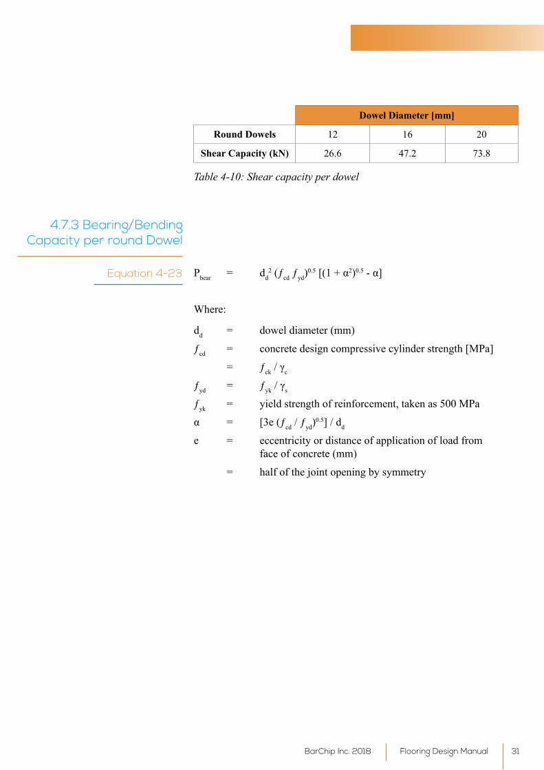
4.7.3 Bearing/Bending Capacity per round Dowel
Pbear = dd2 (ƒcd ƒyd)
0.5[(1+α2)0.5-α]
Where:
dd = dowel diameter (mm)
ƒcd = concrete design compressive cylinder strength [MPa]
= ƒck/γc
ƒyd = ƒyk/γs
ƒyk = yield strength of reinforcement, taken as 500 MPa
α = [3e(ƒcd / ƒyd)0.5] / dd
e = eccentricity or distance of application of load from face of concrete (mm)
= half of the joint opening by symmetry
Equation 4-23
Flooring Design ManualBarChip Inc. 2018 31
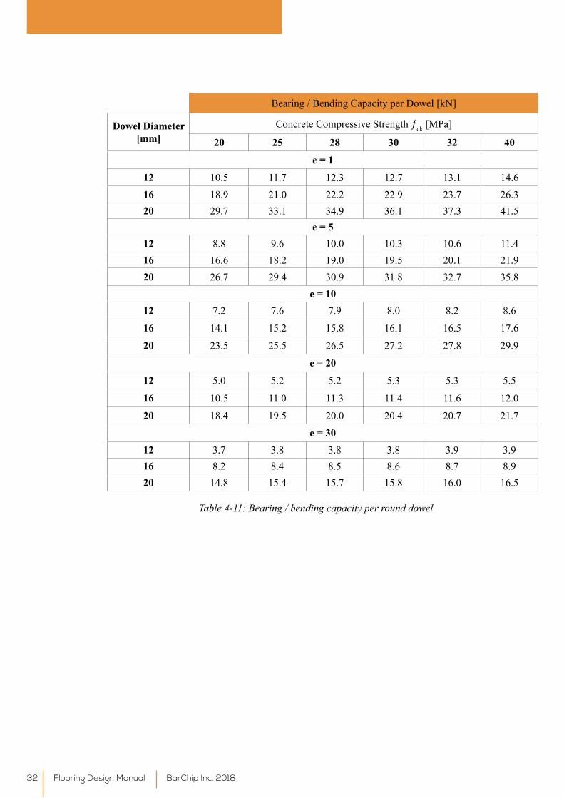
Bearing / Bending Capacity per Dowel [kN]
Dowel Diameter [mm]
Concrete Compressive Strength ƒck [MPa]
20 25 28 30 32 40
e = 1
12 10.5 11.7 12.3 12.7 13.1 14.616 18.9 21.0 22.2 22.9 23.7 26.320 29.7 33.1 34.9 36.1 37.3 41.5
e = 512 8.8 9.6 10.0 10.3 10.6 11.416 16.6 18.2 19.0 19.5 20.1 21.920 26.7 29.4 30.9 31.8 32.7 35.8
e = 1012 7.2 7.6 7.9 8.0 8.2 8.6
16 14.1 15.2 15.8 16.1 16.5 17.6
20 23.5 25.5 26.5 27.2 27.8 29.9
e = 20
12 5.0 5.2 5.2 5.3 5.3 5.5
16 10.5 11.0 11.3 11.4 11.6 12.0
20 18.4 19.5 20.0 20.4 20.7 21.7e = 30
12 3.7 3.8 3.8 3.8 3.9 3.916 8.2 8.4 8.5 8.6 8.7 8.920 14.8 15.4 15.7 15.8 16.0 16.5
Table 4-11: Bearing / bending capacity per round dowel
Flooring Design Manual BarChip Inc. 201832
4.7.4 Bursting Force Capacity of the Dowel
Pburst = 0.035 ks1.5 ƒck
0.5 u1 d1
Where
ks = 1 + (200 / d)0.5≤2.0
u1 = length of the perimeter = 8 dd+0.5hπ
dd = diameter of the dowel
h = slab thickness
d1 = effectivedepthofthedowel,usually0.5h
The maximum capacity of one dowel is the minimum value of shear capacity, bearing/bending capacity or the bursting force capacity.
Pmax.dowel = min (Psh;Pbear;Pburst)
Equation 4-24
Equation 4-25
4.8 Line Loads Line loads shall satisfy the following condition:
Plin*≤Plin
For internal load:
The line load capacity is determined as follows:
Plin=4λMun
For edge load:
The line load capacity at a free edge is determined as follows:
Plin=3λMun
Where:
Mun = hogging moment capacity of plain concrete (refer Table 4-7)
λ = characteristiclength
= [3 k / (Ecm × h3)]0.25
k = modulus of subgrade reaction (refer Table 4-6)
Ecm = short-term modulus of concrete elasticity (refer Table 4-4)
h = slab thickness
Equation 4-26
Equation 4-27
Flooring Design ManualBarChip Inc. 2018 33
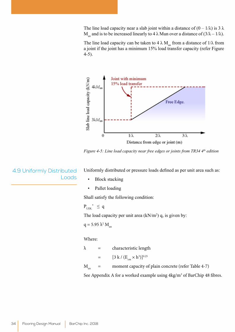
Thelineloadcapacitynearaslabjointwithinadistanceof(0–1/λ)is3λMunandistobeincreasedlinearlyto4λMunoveradistanceof(3/λ–1/λ).
Thelineloadcapacitycanbetakento4λMunfromadistanceof1/λfroma joint if the joint has a minimum 15% load transfer capacity (refer Figure 4-5).
Figure 4-5: Line load capacity near free edges or joints from TR34 4th edition
4.9 Uniformly Distributed Loads
Uniformlydistributedorpressureloadsdefinedasperunitareasuchas:
• Block stacking
• Pallet loading
Shall satisfy the following condition:
PUDL*≤q
The load capacity per unit area (kN/m2) q, is given by:
q = 5.95 λ2 Mun
Where:
λ = characteristic length
= [3 k / (Ecm × h3)]0.25
Mun = moment capacity of plain concrete (refer Table 4-7)
See Appendix A for a worked example using 4kg/m3 of BarChip 48 fibres.
Flooring Design Manual BarChip Inc. 201834
5. Construction of Ground Supported Slabs using BarChip Fibre Reinforcement
5.1 General In general, macro synthetic fibre reinforced concrete ground slabs areconstructedinasimilarmannertoconventionallyreinforcedconcretefloors,without the need to spend time and money in setting up reinforcement before theconcreteispoured.Generally,fibresareorderedthroughthereadymixconcretesupplier,whowilladdthefibrestotheconcreteatthebatchplantandarriveatsitewiththefibrereinforcementalreadyinthefreshconcrete,ready to be placed. This section will outline some of the alternate practices thatarerequired,specifictoBarChipfibrereinforcement,duringbatching,mixingandconstructionoffibrereinforcedgroundsupportedslabs.
5.2 Batching and Mixing WhenbatchingandmixingBarChipmacrosyntheticfibresafewsimplesteps should be followed to ensure homogenous mixing of the fibresthroughout the concrete matrix.
5.2.1 Mixing at the Batch Plant with BarChip Soluble
Bags
• Determine the correct number of BarChip bags per batch
• Add BarChip bags, “Bag and all”, to the empty agitator
• Addsomeinitialbatchwater,approximately12L/kgoffibrequantityper cubic meter of concrete (e.g. add 60 litres for a dose rate of 5.0kg/m3).
• Mix for 1-2 minutes before adding the remaining concrete constituents
• Addtheremainingconstituentsandmixforfiveminutesatmixingspeed before leaving the concrete plant
• When the truck arrives at site, mix at mixing speed for a further 3-5 minutes before discharging concrete from agitator
5.2.2 Mixing at the Batch Plant with an automatic
dosing machine using BarChip pucks
• Addfibrepucks,sandandaggregatetotheagitatorusingaconveyorbelt.
• Add cement and water
• Mix the truck at mixing speed for 5 minutes before leaving the concrete plant
• When the truck arrives at site, mix at mixing speed for a further 3-5 minutes before discharging concrete from agitator
Flooring Design ManualBarChip Inc. 2018 35
5.2.3 Mixing fibres on-site using BarChip soluble
bags
This method is not recommended, however if it must be used, please follow these steps:
• Determine the correct number of bags per batch
• Ensure the concrete has a minimum slump of 120 mm before adding fibres
• Ensure the agitator is at mixing speed before adding bags to the truck
• Add the BarChip bags to the mixer at a maximum rate of 10kg/minute
• After all of the fibres have been loaded, the agitatormustmix atmixing speed for 1 minute per cubic metre of concrete in the truck
Following thesestepswhenbatchingBarChipfibres leads toaconcreteinwhichthefibresarehomogenouslydistributed,andfibreballscanbeavoided. Ifmixed correctly, BarChip fibres will not ball. Regular doseratesofBarChipfibres(i.e.3–6kg/m3) can lead to a reduction in slump of 20-40mm. This should be accommodated for by admixture in the mix design, and not through addition of water on site.
5.3 Finishing
No significant modification to standard procedures or techniques isrequiredwhenfinishingBarChipreinforcedconcrete.However,toachieveacompletely‘fibrefree’surfacefinish,finishingtoolsneedtobekeptflatterforlonger,comparedtonon-fibrereinforcedconcrete.Whenusingpowertrowels,thebladesshouldbekeptflatforthefirsttwopasses,andshouldbeatrightanglestoeachother.Thefinisherwillfindthis‘flat’techniqueprovidesthemwithadequatesurfacepastewhenatthefinalfinishingstage(when the blades start ‘ringing’ against the crisp concrete) and will be able toachieveanydesiredfinishfromnon-sliptohighburnishusingnormaltechniques and timing.
Itisalsogoodpracticewhenusingtoolssuchasabroomorfloattoonlyuse them in a single direction on the concrete surface. If tools are used in both directions, i.e. pushed across the surface away from the concreter, then immediately dragged back towards the concreter, the tendency for thesurfaceto‘tear’andthefibrestobepulledfromthesurfaceincreasessignificantly.
5.3.1 Finishing Techniques
The UK Concrete Society’s TR34 (2013) provides excellent guidance for the construction of joints in industrial flooring. It is recommendedthat joint spacing should not be larger than 6m x 6m for sawn joints, to minimize the risk of cracking as a result of shrinkage and restraint. Proper base preparation and mix design, as well as adequate curing are all advised to further minimize this risk.
Saw cuts should be applied as soon as practically possible once the concrete has set. This again minimizes the occurrence of uncontrolled cracking, by reducing the restraint in the concrete slab.
5.3.2 Joints and Joint Layout
Flooring Design Manual BarChip Inc. 201836
Itisimportanttoemploypropercuringpracticeswhenfinishingconcretefloorstopreventexcessmoisturelossfromthesurfaceoftheconcrete.Thiscan lead to plastic shrinkage cracking, as well as dusting of the concrete surface. Curing compounds can be sprayed on the concrete surface, or alternatively wet hessian can be placed onto the concrete surface and kept damp for at least 24 hours.
A good guide for curing practices is the Concrete Institute of Australia’s (CIA) Recommended Practice for Curing of Concrete (Concrete Institute of Australia, 2011).
5.3.3 Curing
Flooring Design ManualBarChip Inc. 2018 37
AMERICAN SOCIETY FOR TESTING AND MATERIALS 2010. C1116/C1116M-10a: Standard SpecificationforFiber-ReinforcedConcrete.WestConshohocken,USA:ASTMInternational.
BERNARD, E. S. (ed.) 2004. Shotcrete: More Engineering Developments, London: Taylor & Francis.
BERNARD,E.S.2015.EffectofExposureonPost-CrackPerformanceofFRCforTunnelSegments.SEETunnel: Promoting Tunnelling in the SEE Region - ITA WTC 2015 Congress and 41st General Assembly. Dubrovnik, Croatia: WTC.
BURATTI, N., MAZZOTTI, C. & SAVOIA, M. 2011. Post-cracking behaviour of steel and macro-syntheticfibre-reinforcedconcretes.ConstructionandBuildingMaterials,25,2713-2722.CONCRETEINSTITUTE OF AUSTRALIA 2011. Recommended Practice for Curing of Concrete. Sydney, Australia: Concrete Institute of Australia.
EUROPEAN COMMITTEE FOR STANDARDISATION (CEN) 2005. EN 14651:2005 - Test method for metallicfibreconcrete-Measuringtheflexuraltensilestrength(limitofproportionality(LOP),reisudal).Brussels, Belgium: European Committee for Standardisation (CEN).
EUROPEAN COMMITTEE FOR STANDARDISATION (CEN) 2006. EN 14889-2:2006 - Fibres for concrete-Part2:Polymerfibres-Definitions,specificationsandconformity.Brussels,Belgium:EuropeanCommittee for Standardisations.
GOPALARATNAM,V. S.&GETTU,R. 1995.On the characterization of flexural toughness in fiberreinforced concretes. Cement and Concrete Composites, 17, 239-254.
KAUFMANN,J.P.2014.Durabilityperformanceoffiberreinforcedshotcreteinaggressiveenvironments.In: NEGRO, CECILIO & BILFINGER (eds.) World Tunnelling Congress 2014. Iguassa Falls, Brazil.
JUHASZ, K. P., NAGY, L. & SCHAUL, P. 2015. Modelling of the early age shrinkage cracks with steel orsyntheticmacrofibrereinforcementinjointlessfloors.FibreConcrete2015.Prague,CzechRepublic.
MULLER,H.,HAIST,M.&ACOSTA,F.The9thfibInternationalPhDSymposiuminCivilEngineering.The9thfibInternationalPhDSymposiuminCivilEngineering,2012KarlsruheInstituteofTechnology.KITScientificPublishing.
RILEM TC 162-TDF, T. A. D. M. F. S. F. R. C. 2003. sigma-epsilon-design method. Materials and Structures, 36, 560-567.
SOUTSOS,M.N.,LE,T.T.&LAMPROPOULOS,A.P.2012.Flexuralperformanceoffibrereinforcedconcretemadewithsteelandsyntheticfibres.ConstructionandBuildingMaterials,36,704-710.
THE CONCRETE SOCIETY 2007. Technical Report No. 65: Guidance on the use of Macro- synthetic-fibre-reinforcedConcrete.Surrey,UnitedKingdom:TheConcreteSociety.
THE CONCRETE SOCIETY 2013. Technical Report No. 34: Concrete Industrial Ground Floors - A guide to design and construction. Surrey, United Kingdom: The Concrete Society.
6. References
Flooring Design Manual BarChip Inc. 201838

Flooring Design ManualBarChip Inc. 2018 39
Appendix A - Worked Design
Example
Flooring Design Manual BarChip Inc. 201840
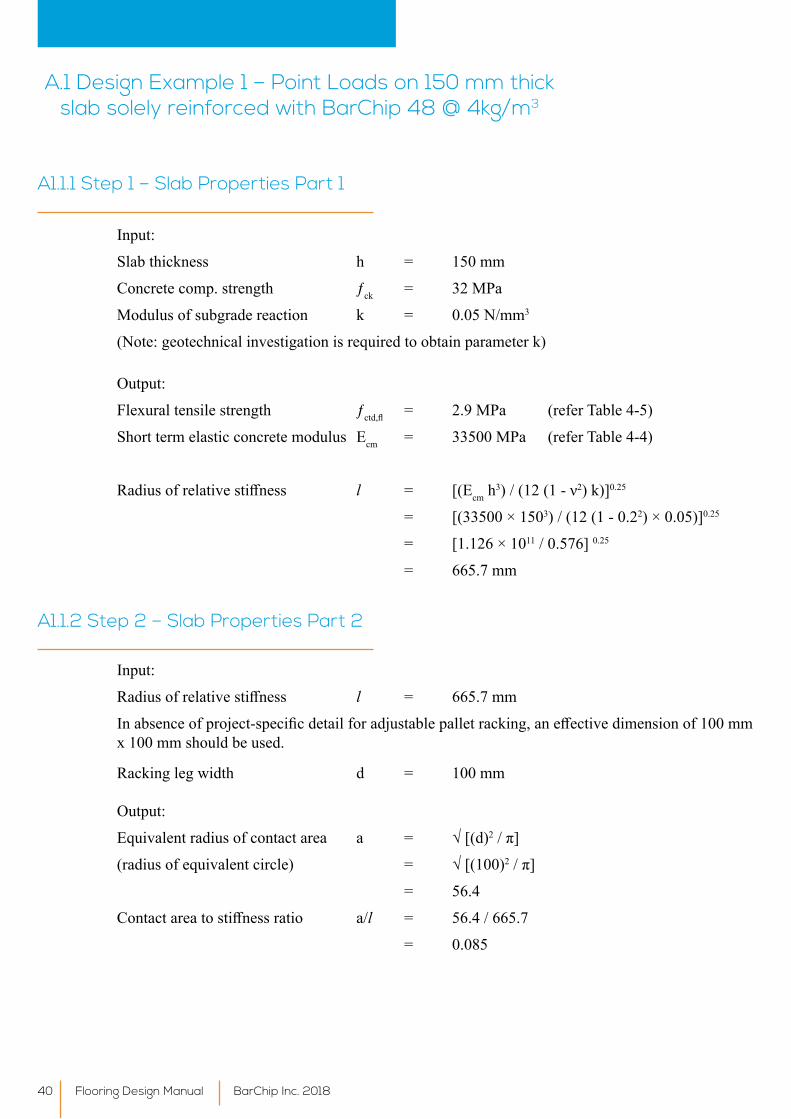
Input:
Slab thickness h = 150 mm
Concrete comp. strength ƒck = 32 MPa
Modulus of subgrade reaction k = 0.05 N/mm3
(Note: geotechnical investigation is required to obtain parameter k)
Output:
Flexural tensile strength ƒctd,fl = 2.9 MPa (refer Table 4-5)
Short term elastic concrete modulus Ecm = 33500 MPa (refer Table 4-4)
Radiusofrelativestiffness l = [(Ecm h3)/(12(1-ν2) k)]0.25
= [(33500 × 1503) / (12 (1 - 0.22) × 0.05)]0.25
= [1.126 × 10¹¹ / 0.576] 0.25
= 665.7 mm
A.1 Design Example 1 – Point Loads on 150 mm thick slab solely reinforced with BarChip 48 @ 4kg/m3
A1.1.1 Step 1 – Slab Properties Part 1
Input:
Radiusofrelativestiffness l = 665.7 mm
Inabsenceofproject-specificdetailforadjustablepalletracking,aneffectivedimensionof100mmx 100 mm should be used.
Racking leg width d = 100 mm
Output:
Equivalentradiusofcontactarea a = √[(d)2/π]
(radiusofequivalentcircle) = √[(100)2/π]
= 56.4
Contactareatostiffnessratio a/l = 56.4 / 665.7
= 0.085
A1.1.2 Step 2 – Slab Properties Part 2
Flooring Design ManualBarChip Inc. 2018 41
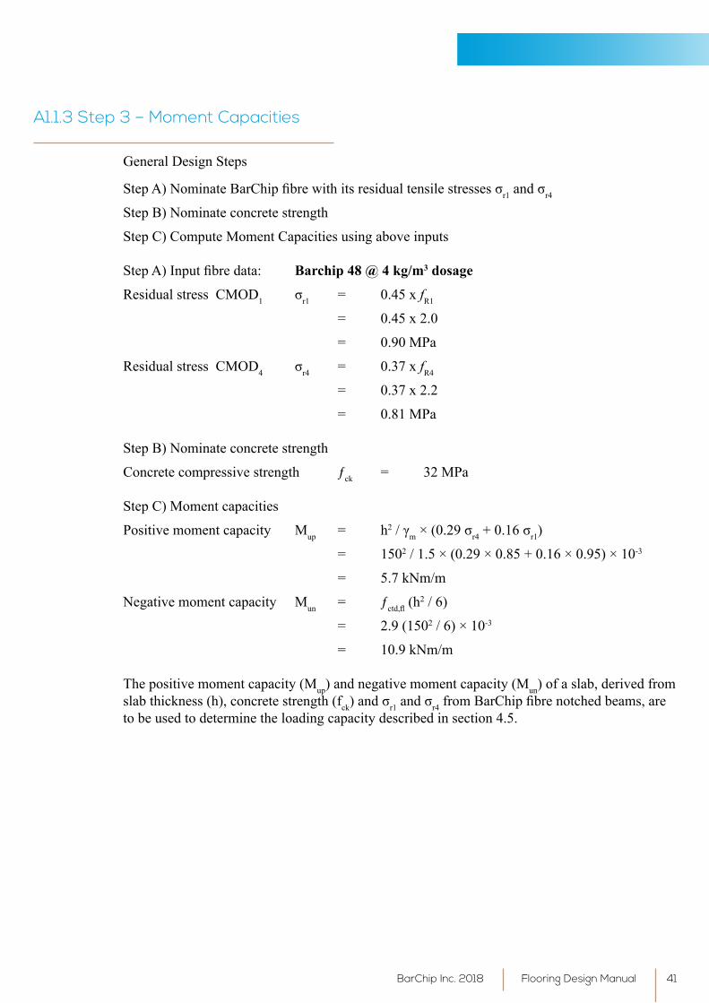
General Design Steps
StepA)NominateBarChipfibrewithitsresidualtensilestressesσr1andσr4
Step B) Nominate concrete strength
Step C) Compute Moment Capacities using above inputs
StepA)Inputfibredata: Barchip 48 @ 4 kg/m3 dosage
Residual stress CMOD1 σr1 = 0.45 x fR1
= 0.45 x 2.0
= 0.90 MPa
Residual stress CMOD4 σr4 = 0.37 x fR4
= 0.37 x 2.2
= 0.81 MPa
Step B) Nominate concrete strength
Concrete compressive strength ƒck = 32 MPa
Step C) Moment capacities
Positive moment capacity Mup = h2/γm×(0.29σr4+0.16σr1)
= 1502 / 1.5 × (0.29 × 0.85 + 0.16 × 0.95) × 10-3
= 5.7 kNm/m
Negative moment capacity Mun = ƒctd,fl (h2 / 6)
= 2.9 (1502 / 6) × 10-3
= 10.9 kNm/m
The positive moment capacity (Mup) and negative moment capacity (Mun) of a slab, derived from slab thickness (h), concrete strength (fck)andσr1andσr4fromBarChipfibrenotchedbeams,areto be used to determine the loading capacity described in section 4.5.
A1.1.3 Step 3 – Moment Capacities
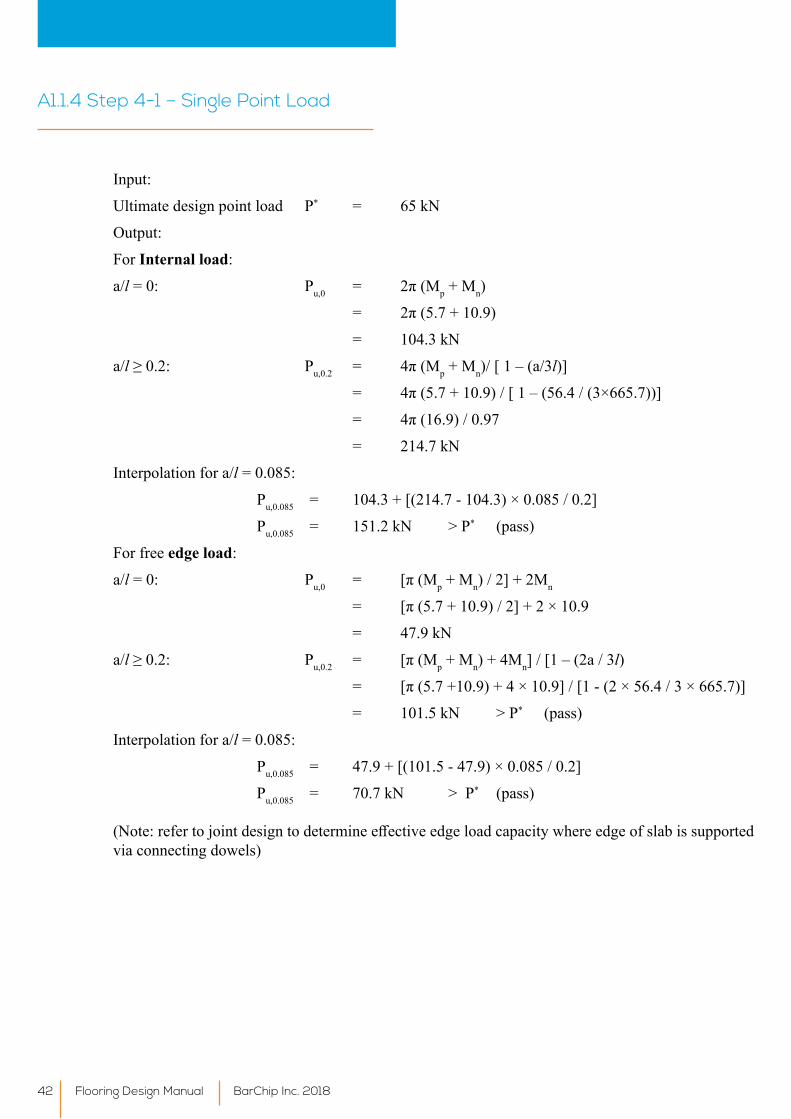
Input:
Ultimate design point load P* = 65 kN
Output:
For Internal load:
a/l = 0: Pu,0 = 2π(Mp + Mn)
= 2π(5.7+10.9)
= 104.3 kN
a/l≥0.2: Pu,0.2 = 4π(Mp + Mn)/ [ 1 – (a/3l)]
= 4π(5.7+10.9)/[1–(56.4/(3×665.7))]
= 4π(16.9)/0.97
= 214.7 kN
Interpolation for a/l = 0.085:
Pu,0.085 = 104.3 + [(214.7 - 104.3) × 0.085 / 0.2]
Pu,0.085 = 151.2 kN > P* (pass)
For free edge load:
a/l = 0: Pu,0 = [π(Mp + Mn) / 2] + 2Mn
= [π(5.7+10.9)/2]+2×10.9
= 47.9 kN
a/l≥0.2: Pu,0.2 = [π(Mp + Mn) + 4Mn] / [1 – (2a / 3l)
= [π(5.7+10.9)+4×10.9]/[1-(2×56.4/3×665.7)]
= 101.5 kN > P* (pass)
Interpolation for a/l = 0.085:
Pu,0.085 = 47.9 + [(101.5 - 47.9) × 0.085 / 0.2]
Pu,0.085 = 70.7 kN > P* (pass)
(Note:refertojointdesigntodetermineeffectiveedgeloadcapacitywhereedgeofslabissupportedvia connecting dowels)
A1.1.4 Step 4-1 – Single Point Load
Flooring Design Manual BarChip Inc. 201842
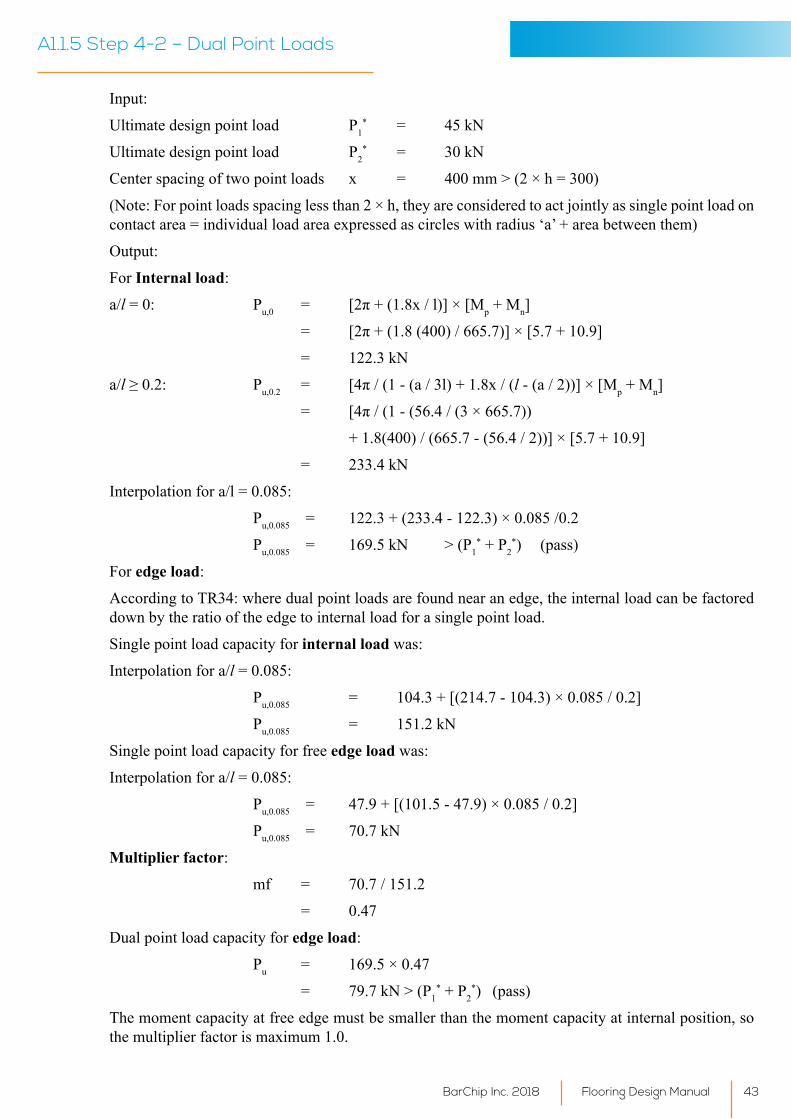
Input:
Ultimate design point load P1* = 45 kN
Ultimate design point load P2* = 30 kN
Center spacing of two point loads x = 400 mm > (2 × h = 300)
(Note: For point loads spacing less than 2 × h, they are considered to act jointly as single point load on contact area = individual load area expressed as circles with radius ‘a’ + area between them)
Output:
For Internal load:
a/l = 0: Pu,0 = [2π+(1.8x/l)]×[Mp + Mn]
= [2π+(1.8(400)/665.7)]×[5.7+10.9]
= 122.3 kN
a/l≥0.2: Pu,0.2 = [4π/(1-(a/3l)+1.8x/(l - (a / 2))] × [Mp + Mn]
= [4π/(1-(56.4/(3×665.7))
+ 1.8(400) / (665.7 - (56.4 / 2))] × [5.7 + 10.9]
= 233.4 kN
Interpolation for a/l = 0.085:
Pu,0.085 = 122.3 + (233.4 - 122.3) × 0.085 /0.2
Pu,0.085 = 169.5 kN > (P1* + P2
*) (pass)
For edge load:
According to TR34: where dual point loads are found near an edge, the internal load can be factored down by the ratio of the edge to internal load for a single point load.
Single point load capacity for internal load was:
Interpolation for a/l = 0.085:
Pu,0.085 = 104.3 + [(214.7 - 104.3) × 0.085 / 0.2]
Pu,0.085 = 151.2 kN
Single point load capacity for free edge load was:
Interpolation for a/l = 0.085:
Pu,0.085 = 47.9 + [(101.5 - 47.9) × 0.085 / 0.2]
Pu,0.085 = 70.7 kN
Multiplier factor:
mf = 70.7 / 151.2
= 0.47
Dual point load capacity for edge load:
Pu = 169.5 × 0.47
= 79.7 kN > (P1* + P2
*) (pass)
The moment capacity at free edge must be smaller than the moment capacity at internal position, so the multiplier factor is maximum 1.0.
A1.1.5 Step 4-2 – Dual Point Loads
Flooring Design ManualBarChip Inc. 2018 43
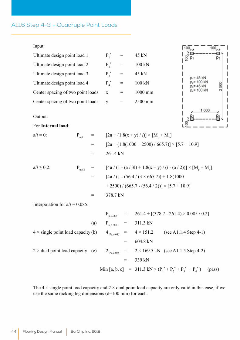
Input:
Ultimate design point load 1 P1* = 45 kN
Ultimate design point load 2 P2* = 100 kN
Ultimate design point load 3 P3* = 45 kN
Ultimate design point load 4 P4* = 100 kN
Center spacing of two point loads x = 1000 mm
Center spacing of two point loads y = 2500 mm
Output:
For Internal load:
a/l = 0: Pu,0 = [2π+(1.8(x+y)/l)] × [Mp + Mn]
= [2π+(1.8(1000+2500)/665.7)]×[5.7+10.9]
= 261.4 kN
a/l≥0.2: Pu,0.2 = [4π/(1-(a/3l)+1.8(x+y)/(l - (a / 2))] × [Mp + Mn]
= [4π/(1-(56.4/(3×665.7))+1.8(1000
+ 2500) / (665.7 - (56.4 / 2))] × [5.7 + 10.9]
= 378.7 kN
Interpolation for a/l = 0.085:
Pu,0.085 = 261.4 + [(378.7 - 261.4) × 0.085 / 0.2]
(a) Pu,0.085 = 311.3 kN
4 × single point load capacity (b) 4 Pu,o.085 = 4 × 151.2 (see A1.1.4 Step 4-1)
= 604.8 kN
2 × dual point load capacity (c) 2 Pu,o.085 = 2 × 169.5 kN (see A1.1.5 Step 4-2)
= 339 kN
Min [a, b, c] = 311.3 kN > (P1* + P2
* + P3* + P4
* ) (pass)
The 4 × single point load capacity and 2 × dual point load capacity are only valid in this case, if we use the same racking leg dimensions (d=100 mm) for each.
A1.1.6 Step 4-3 – Quadruple Point Loads
Flooring Design Manual BarChip Inc. 201844
Flooring Design ManualBarChip Inc. 2018 45
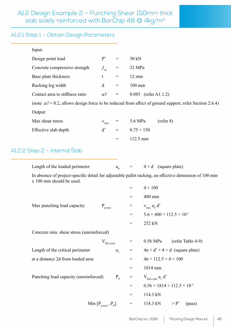
A1.2 Design Example 2 – Punching Shear 150mm thick slab solely reinforced with BarChip 48 @ 4kg/m3
Input:
Design point load P* = 30 kN
Concrete compressive strength ƒck = 32 MPa
Base plate thickness t = 12 mm
Racking leg width d = 100 mm
Contactareatostiffnessratio a/l = 0.085 (refer A1.1.2)
(note: a/l<0.2,allowsdesignforcetobereducedfromeffectofgroundsupport,referSection2.6.4)
Output:
Max shear stress vmax = 5.6 MPa (refer 8)
Effectiveslabdepth d* = 0.75 × 150
= 112.5 mm
A1.2.1 Step 1 – Obtain Design Parameters
Length of the loaded perimeter u0 = 4 × d (square plate)
Inabsenceofproject-specificdetailforadjustablepalletracking,aneffectivedimensionof100mmx 100 mm should be used. = 4 × 100
= 400 mm
Max punching load capacity Pp,max = vmax u0 d*
= 5.6 × 400 × 112.5 × 10-3
= 252 kN
Concrete min. shear stress (unreinforced)
VRd,c,min = 0.56 MPa (refer Table 4-9)
Length of the critical perimeter u1 = 4π×d* + 4 × d (square plate)
atadistance2dfromloadedarea = 4π×112.5+4×100
= 1814 mm
Punching load capacity (unreinforced) PP = VRd,c,min u1 d*
= 0.56 × 1814 × 112.5 × 10-3
= 114.3 kN
Min [Pp,max , PP] = 114.3 kN > P* (pass)
A1.2.2 Step 2 – Internal Slab
Flooring Design Manual BarChip Inc. 201846
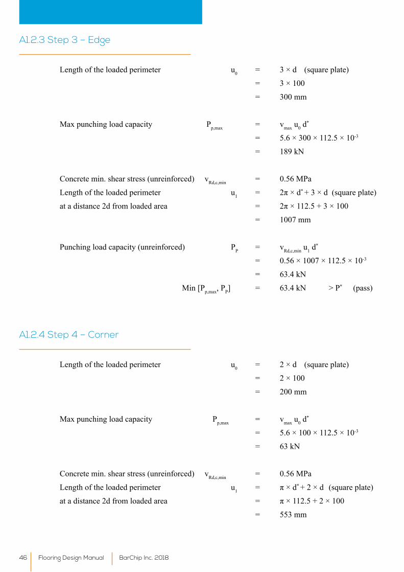
Length of the loaded perimeter u0 = 3 × d (square plate)
= 3 × 100
= 300 mm
Max punching load capacity Pp,max = vmax u0 d*
= 5.6 × 300 × 112.5 × 10-3
= 189 kN
Concrete min. shear stress (unreinforced) vRd,c,min = 0.56 MPa
Length of the loaded perimeter u1 = 2π×d* + 3 × d (square plate)
atadistance2dfromloadedarea = 2π×112.5+3×100
= 1007 mm
Punching load capacity (unreinforced) PP = vRd,c,min u1 d*
= 0.56 × 1007 × 112.5 × 10-3
= 63.4 kN
Min [Pp,max, PP] = 63.4 kN > P* (pass)
A1.2.3 Step 3 – Edge
Length of the loaded perimeter u0 = 2 × d (square plate)
= 2 × 100
= 200 mm
Max punching load capacity Pp,max = vmax u0 d*
= 5.6 × 100 × 112.5 × 10-3
= 63 kN
Concrete min. shear stress (unreinforced) vRd,c,min = 0.56 MPa
Length of the loaded perimeter u1 = π×d* + 2 × d (square plate)
atadistance2dfromloadedarea = π×112.5+2×100
= 553 mm
A1.2.4 Step 4 – Corner
Flooring Design ManualBarChip Inc. 2018 47
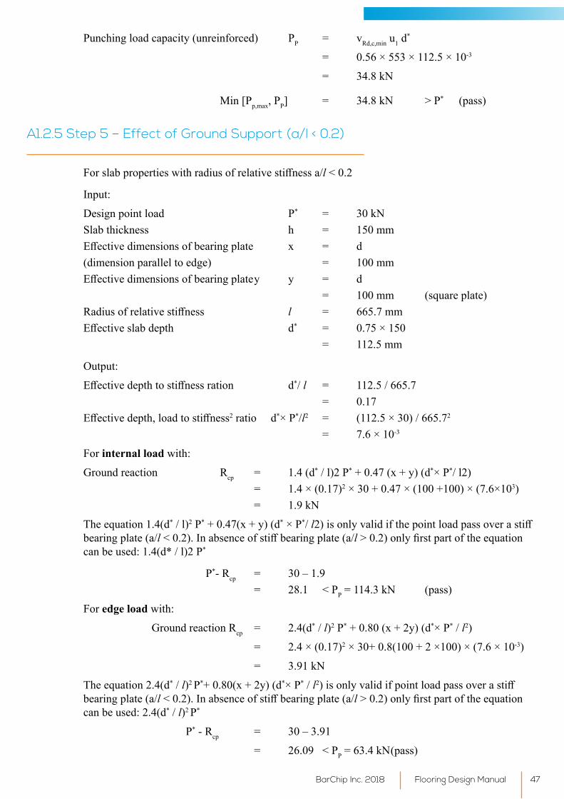
Punching load capacity (unreinforced) PP = vRd,c,min u1 d*
= 0.56 × 553 × 112.5 × 10-3
= 34.8 kN
Min [Pp,max, PP] = 34.8 kN > P* (pass)
Forslabpropertieswithradiusofrelativestiffnessa/l <0.2
Input:
Design point load P* = 30 kNSlab thickness h = 150 mm Effectivedimensionsofbearingplate x = d(dimension parallel to edge) = 100 mm Effectivedimensionsofbearingplatey y = d = 100 mm (square plate)Radiusofrelativestiffness l = 665.7 mmEffectiveslabdepth d* = 0.75 × 150 = 112.5 mm
Output:
Effectivedepthtostiffnessration d*/ l = 112.5 / 665.7 = 0.17Effectivedepth,loadtostiffness2 ratio d*× P*/l2 = (112.5 × 30) / 665.72
= 7.6 × 10⁻³
For internal load with:
Ground reaction Rcp = 1.4 (d* / l)2 P* + 0.47 (x + y) (d*× P*/ l2) = 1.4 × (0.17)2 × 30 + 0.47 × (100 +100) × (7.6×103) = 1.9 kN
The equation 1.4(d* / l)2 P* + 0.47(x + y) (d* × P*/ l2)isonlyvalidifthepointloadpassoverastiffbearing plate (a/l<0.2).Inabsenceofstiffbearingplate(a/l>0.2)onlyfirstpartoftheequationcan be used: 1.4(d* / l)2 P*
P*- Rcp = 30 – 1.9 = 28.1 <PP = 114.3 kN (pass)
For edge load with:
Ground reaction Rcp = 2.4(d* / l)2 P* + 0.80 (x + 2y) (d*× P* / l2)
= 2.4 × (0.17)2 × 30+ 0.8(100 + 2 ×100) × (7.6 × 10-3)
= 3.91 kN
The equation 2.4(d* / l)2 P*+ 0.80(x + 2y) (d*× P* / l2)isonlyvalidifpointloadpassoverastiffbearing plate (a/l <0.2).Inabsenceofstiffbearingplate(a/l>0.2)onlyfirstpartoftheequationcan be used: 2.4(d* / l)2 P*
P* - Rcp = 30 – 3.91
= 26.09 <PP = 63.4 kN (pass)
A1.2.5 Step 5 – Effect of Ground Support (a/l < 0.2)
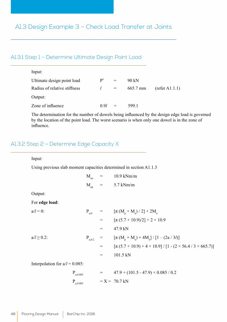
Input:
Ultimate design point load P* = 90 kN
Radiusofrelativestiffness l = 665.7 mm (refer A1.1.1)
Output:
Zoneofinfluence 0.9l = 599.1
Thedeterminationforthenumberofdowelsbeinginfluencedbythedesignedgeloadisgovernedby the location of the point load. The worst scenario is when only one dowel is in the zone of influence.
A1.3.1 Step 1 – Determine Ultimate Design Point Load
A1.3 Design Example 3 – Check Load Transfer at Joints
Input:
Using previous slab moment capacities determined in section A1.1.3
Mun = 10.9 kNm/m
Mup = 5.7 kNm/m
Output:
For edge load:
a/l = 0: Pu,0 = [π(Mp + Mn) / 2] + 2Mn
= [π(5.7+10.9)/2]+2×10.9
= 47.9 kN
a/l≥0.2: Pu,0.2 = [π(Mp + Mn) + 4Mn] / [1 – (2a / 3l)]
= [π(5.7+10.9)+4×10.9]/[1-(2×56.4/3×665.7)]
= 101.5 kN
Interpolation for a/l = 0.085:
Pu,0.085 = 47.9 + (101.5 - 47.9) × 0.085 / 0.2
Pu,0.085 = X = 70.7 kN
A1.3.2 Step 2 – Determine Edge Capacity X
Flooring Design Manual BarChip Inc. 201848
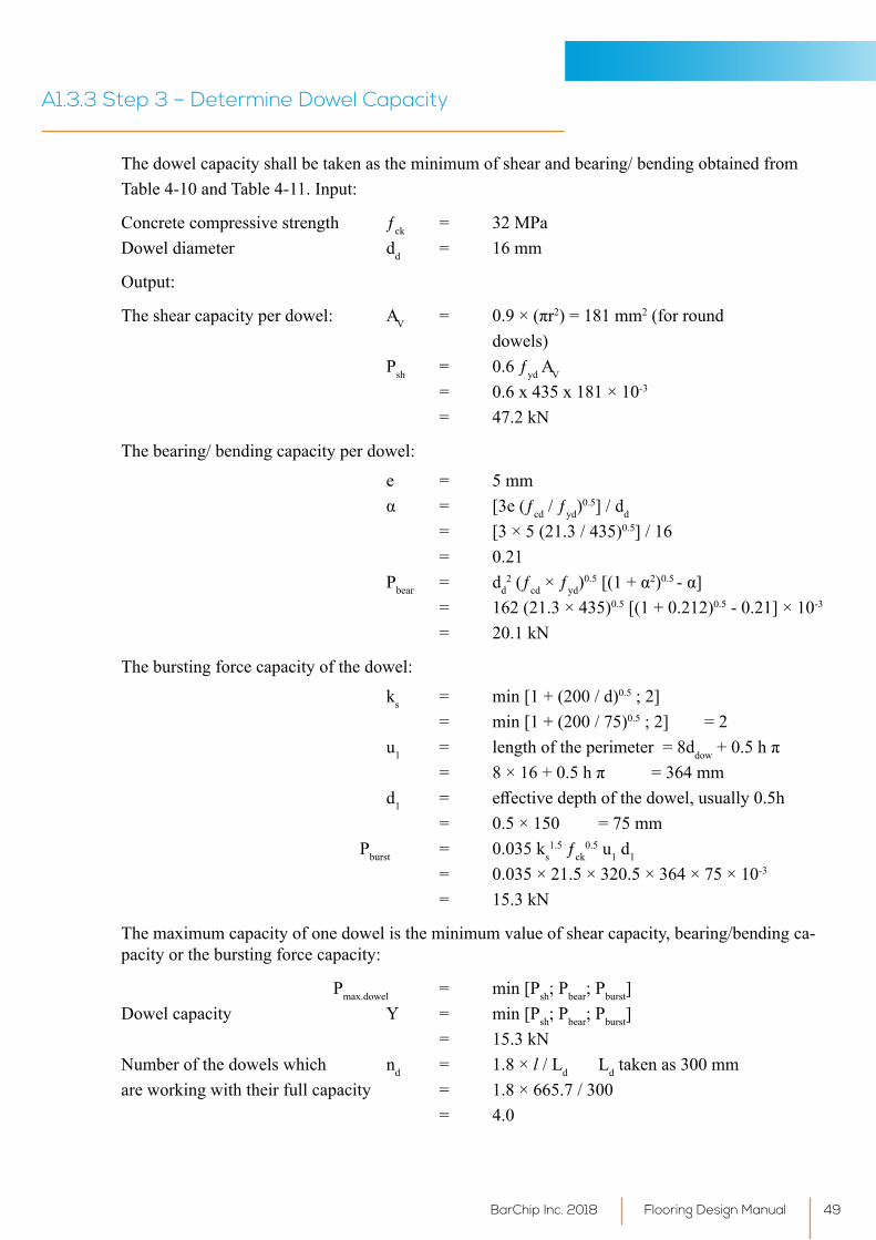
The dowel capacity shall be taken as the minimum of shear and bearing/ bending obtained fromTable 4-10 and Table 4-11. Input:
Concrete compressive strength ƒck = 32 MPa Dowel diameter dd = 16 mm
Output:
The shear capacity per dowel: AV = 0.9×(πr2) = 181 mm2 (for round dowels) Psh = 0.6 ƒyd AV
= 0.6 x 435 x 181 × 10-3
= 47.2 kN
The bearing/ bending capacity per dowel:
e = 5 mm α = [3e(ƒcd / ƒyd)
0.5] / dd
= [3 × 5 (21.3 / 435)0.5] / 16 = 0.21 Pbear = dd
2 (ƒcd × ƒyd)0.5[(1+α2)0.5 -α]
= 162 (21.3 × 435)0.5 [(1 + 0.212)0.5 - 0.21] × 10-3
= 20.1 kN
The bursting force capacity of the dowel:
ks = min [1 + (200 / d)0.5;2] = min [1 + (200 / 75)0.5;2] =2 u1 = length of the perimeter = 8ddow+0.5hπ = 8×16+0.5hπ =364mm d1 = effectivedepthofthedowel,usually0.5h = 0.5 × 150 = 75 mm Pburst = 0.035 ks
1.5 ƒck0.5 u1 d1
= 0.035 × 21.5 × 320.5 × 364 × 75 × 10-3
= 15.3 kN
The maximum capacity of one dowel is the minimum value of shear capacity, bearing/bending ca-pacity or the bursting force capacity:
Pmax.dowel = min [Psh;Pbear;Pburst]Dowel capacity Y = min [Psh;Pbear;Pburst] = 15.3 kNNumber of the dowels which nd = 1.8 × l / Ld Ld taken as 300 mmare working with their full capacity = 1.8 × 665.7 / 300 = 4.0
A1.3.3 Step 3 – Determine Dowel Capacity
Flooring Design ManualBarChip Inc. 2018 49
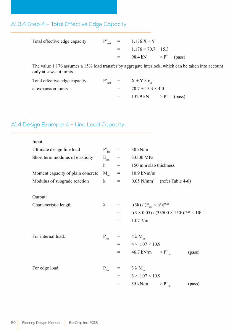
Totaleffectiveedgecapacity P’u,0 = 1.176 X + Y
= 1.176 × 70.7 + 15.3
= 98.4 kN > P* (pass)
The value 1.176 assumes a 15% load transfer by aggregate interlock, which can be taken into account only at saw-cut joints.
Totaleffectiveedgecapacity P’u,0 = X + Y × nd
at expansion joints = 70.7 + 15.3 × 4.0
= 132.9 kN > P* (pass)
A1.3.4 Step 4 – Total Effective Edge Capacity
Input:
Ultimate design line load P*lin = 30 kN/m
Short term modulus of elasticity Ecm = 33500 MPa
h = 150 mm slab thickness
Moment capacity of plain concrete Mun = 10.9 kNm/m
Modulus of subgrade reaction k = 0.05 N/mm3 (refer Table 4-6)
Output:
Characteristiclength λ = [(3k)/(Ecm × h3)]0.25
= [(3 × 0.05) / (33500 × 1503)]0.25 × 103
= 1.07 1/m
For internal load: Plin = 4λMun
= 4 × 1.07 × 10.9
= 46.7 kN/m > P*lin (pass)
For edge load: Plin = 3λMun
= 3 × 1.07 × 10.9
= 35 kN/m > P*lin (pass)
A1.4 Design Example 4 – Line Load Capacity
Flooring Design Manual BarChip Inc. 201850
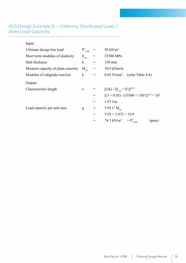
Input:
Ultimate design line load P*UDL = 50 kN/m2
Short term modulus of elasticity Ecm = 33500 MPa
Slab thickness h = 150 mm
Moment capacity of plain concrete Mun = 10.9 kNm/m
Modulus of subgrade reaction k = 0.05 N/mm3 (refer Table 4-6)
Output:
Characteristiclength λ = [(3k)/(Ecm × h3)]0.25
= [(3 × 0.05) / (33500 × 1503)]0.25 × 103
= 1.07 l/m
Loadcapacityperunitarea q = 5.95λ2 Mun
= 5.95 × 1.072 × 10.9
= 74.3 kN/m2 > P*UDL (pass)
A1.5 Design Example 5 – Uniformly Distributed Load / Area Load Capacity
Flooring Design ManualBarChip Inc. 2018 51

Appendix B - Project Case
Studies
Flooring Design Manual BarChip Inc. 201852
Project Highlights Total M2 YearCarrefour Itapevi Distribution Centre 49,000 2009
Regina Festas 22,000 2010
Santher Braganca Paulista 15,000 2010
Hermes Rio de Janeiro 70,000 2010
Siemens 7,500 2010
Eucatex 35,000 2010
LG Electronics 12,000 2011
Aguas lindas Shopping Centre, Goiânia 8,000 2011
Sony Electronics 12,000 2012
Brooklyn Emprendimentos 12,000 2012
Libercon 25,000 2012
Hypermarcas Goiânia 28,000 2012
Pilot Pen 8,800 2012
John Deere 20,000 2013
Contagem Shopping Centre 120,000 2013
Iguatemi Rio Preto Shopping Centre 85,000 2013
Logixx Distribution Centre 25,000 2013
HABOM Aircraft Maintenance Facility 155,000 2013
IKEA 7,000 2014
Westfield Miranda Shopping Centre 12,000 2014
BMW Manufacturing Plant, Brazil 90,000 2014
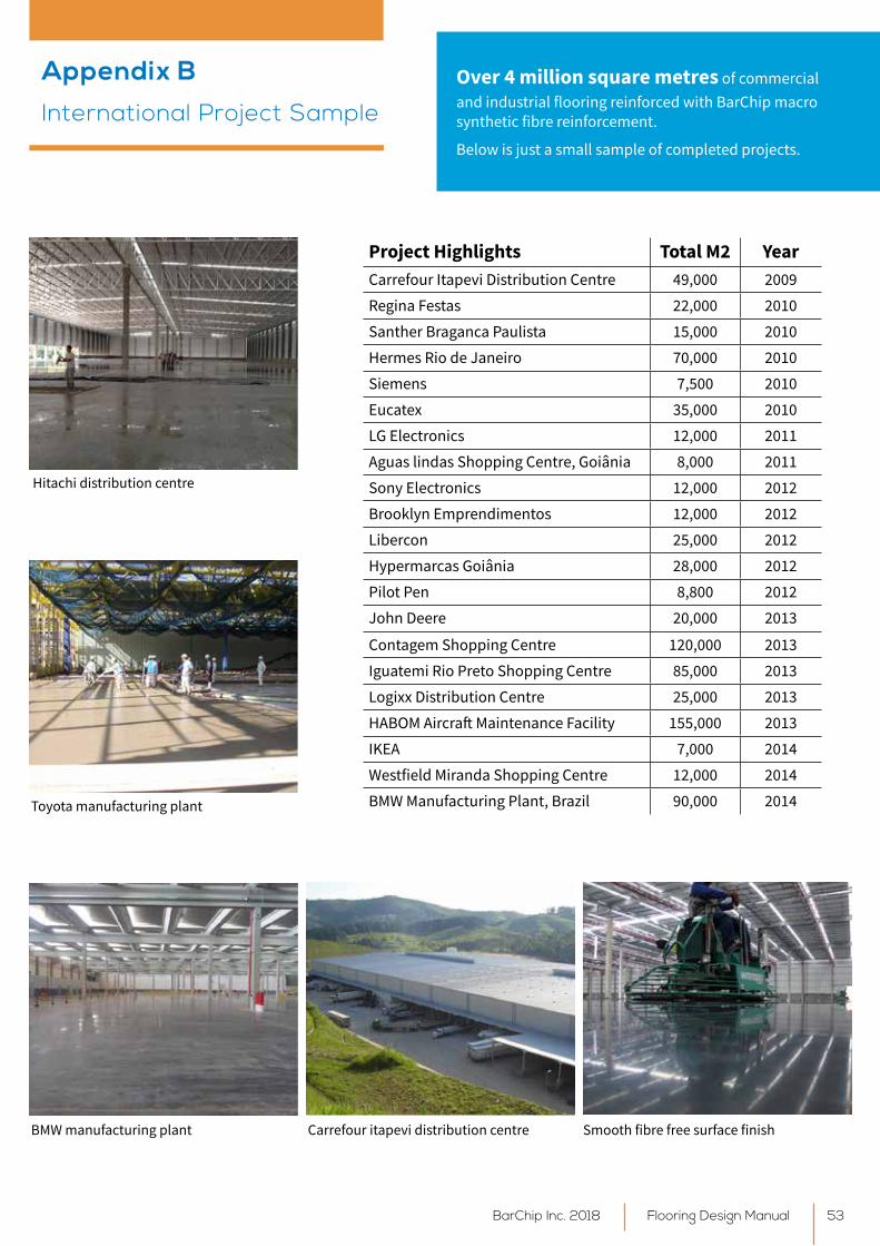
Over 4 million square metres of commercial and industrial flooring reinforced with BarChip macro synthetic fibre reinforcement.
Below is just a small sample of completed projects.
Hitachi distribution centre
Toyota manufacturing plant
Carrefour itapevi distribution centreBMW manufacturing plant Smooth fibre free surface finish
Appendix BInternational Project Sample
Flooring Design ManualBarChip Inc. 2018 53
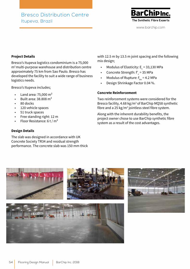
Project Details
Bresco’s Itupeva logistics condominium is a 75,000 m2 multi-purpose warehouse and distribution centre approximately 75 km from Sao Paulo. Bresco has developed the facility to suit a wide range of business logistics needs.
Bresco’s Itupeva includes;
• Land area: 75,000 m² • Built area: 38.808 m² • 80 docks• 120 vehicle spaces • 51 truck spaces • Free standing right: 12 m• Floor Resistance: 6 t / m²
Design Details
The slab was designed in accordance with UK Concrete Society TR34 and residual strength performance. The concrete slab was 150 mm thick
with 12.5 m by 13.5 m joint spacing and the following mix design;
• Modulus of Elasticity: Ec = 33,130 MPa• Concrete Strength: f'c = 35 MPa• Modulus of Rupture: ftm = 4.2 MPa• Design Shrinkage Factor 0.04 %.
Concrete Reinforcement
Two reinforcement systems were considered for the Bresco facility, 4.68 kg/m3 of BarChip MQ58 synthetic fibre and a 25 kg/m3 jointless steel fibre system.
Along with the inherent durability benefits, the project owner chose to use BarChip synthetic fibre system as a result of the cost advantages.
Bresco Distribution Centre Itupeva, Brazil
Flooring Design Manual BarChip Inc. 201854
www.barchip.com

Turkish Fast Track Rail
With 20 fast track rail projects planned or under construction it’s safe to say Turkey is in the midst of a rail revolution! The busiest of these is these lines is the Ankara to Istanbul Fast Track Rail which will connect Turkey’s two largest cities.
Technical Aspects
• 533 km long
• Max speed: 250 km/h.
• Double lines, electrified: (25 kV, 50 Hz AC)
• Current travel time: 4 hours. Target is 3 hours.
• Min radius: 3500 m
• Standard railway gauge: (1435 mm)
• Max gradient: 1,6%
• Max cant: 130 mm
• Project cost: 274.6 million
Ankara Fast Track Station
Included in the project is the construction of a new train station and maintenance complex at Ankara. The 29 ha facility consists of workshop buildings, an office building and the station itself.
Ankara High Speed Train Station and Maintenance Complex
Ankara’s New Fast Track Train Station Project with its 200,000 m2 closed area is a Build-Operate-Transfer model project and once the Project is completed, it will serve up to 50,000 passengers daily.
BarChip macro synthetic fibres are being used on the 10 cm thick topping concrete of the station’s 50,000 m2 indoor parking lot. With the usage of BarChip macro synthetic fibres, approximately 2,000 m2 of concrete is being poured per day.
By using BarChip macro synthetic fibre as a replacement for steel mesh the project contract regularly achieved a 35% to 40% increase in construction speeds. On top of direct material cost savings, the site efficiency delivered substantial labour cost reductions and allowed for faster construction.
• Total Project Area: 200,000 m2
• Total BarChip Used Area: 50,000 m2
• Concrete Thickness: 10 cm
• Concrete Type: C25
• Loads: 750 kg/m2
• Contractor: CLK JV.
• Concrete Reinforcement: BarChip 48
Owner: General Directorate of Turkish State RailwaysGeneral Contractor: CLK JV
Ankara Fast Track Train Station Ankara, Turkey
Flooring Design ManualBarChip Inc. 2018 55
www.barchip.com
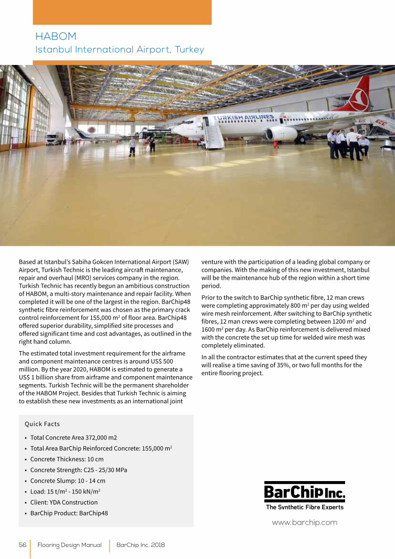
Based at Istanbul’s Sabiha Gokcen International Airport (SAW) Airport, Turkish Technic is the leading aircraft maintenance, repair and overhaul (MRO) services company in the region. Turkish Technic has recently begun an ambitious construction of HABOM, a multi-story maintenance and repair facility. When completed it will be one of the largest in the region. BarChip48 synthetic fibre reinforcement was chosen as the primary crack control reinforcement for 155,000 m2 of floor area. BarChip48 offered superior durability, simplified site processes and offered significant time and cost advantages, as outlined in the right hand column.
The estimated total investment requirement for the airframe and component maintenance centres is around US$ 500 million. By the year 2020, HABOM is estimated to generate a US$ 1 billion share from airframe and component maintenance segments. Turkish Technic will be the permanent shareholder of the HABOM Project. Besides that Turkish Technic is aiming to establish these new investments as an international joint
venture with the participation of a leading global company or companies. With the making of this new investment, Istanbul will be the maintenance hub of the region within a short time period.
Prior to the switch to BarChip synthetic fibre, 12 man crews were completing approximately 800 m2 per day using welded wire mesh reinforcement. After switching to BarChip synthetic fibres, 12 man crews were completing between 1200 m2 and 1600 m2 per day. As BarChip reinforcement is delivered mixed with the concrete the set up time for welded wire mesh was completely eliminated.
In all the contractor estimates that at the current speed they will realise a time saving of 35%, or two full months for the entire flooring project.
Quick Facts
• Total Concrete Area 372,000 m2
• Total Area BarChip Reinforced Concrete: 155,000 m2
• Concrete Thickness: 10 cm
• Concrete Strength: C25 - 25/30 MPa
• Concrete Slump: 10 - 14 cm
• Load: 15 t/m2 - 150 kN/m2
• Client: YDA Construction
• BarChip Product: BarChip48
HABOM Istanbul International Airport, Turkey
Flooring Design Manual BarChip Inc. 201856
www.barchip.com

Alekon Cargo - is a state of the art provider of forwarding services, storage and warehousing services and handling of all types of cargo. Built in 2007 - 08 the Alekon Cargo Logistics Hub, located in Tallinn, Estonia, is a state of the art logistics centre incorporating road, rail and port services over a 12.5 hectare site.
The complex is equipped with warehouses, covered and open storage areas, three railway tracks and high-performance warehousing and cargo handling equipment. Warehousing and Storage Facilities on-site Include;
• 90,000 m2 customs terminal area (75% monolithic concrete surfacing, 25% asphalt)
• 9,000 m2 warehouse with 12 m high shelf stands and 15,000 standard pallet capacity
• 7,000 m2 warehouse with 12,000 standard pallet capacity and 16t capacity overhead cranes
• 3,500 TEU container yard• 22,000 m2 parking yard for freight motor transport• 3 railway branches with 1.3 km of total frontage.
BarChip structural synthetic fibre was used as the sole reinforcement in over 40,000 m2 of the Logistic Hub’s concrete flooring;
Concrete Class C30 C37
Dose Rate 7 kg/m3 5 kg/m3
Slab Thickness 180 mm 150 mm
UDL acc. 6 T/m2 4 T/m2
By incorporating the use of BarChip synthetic fibre reinforcement, flooring contractors Savekate were able to realise a number of benefits;
• Eliminated the placement, storage and transport of steel mesh
• Increased durability and eliminated the risk of corrosion. BarChip synthetic fibre is inert and will never rust.
• Increased concrete toughness• Increased on-site productivity• Reduced overall costs• Improved temperature and shrinkage crack control
Since construction in 2007 - 08 the concrete flooring has performed perfectly.
The selection of BarChip synthetic fibre as the primary concrete reinforcement eliminated significant man hours during construction and since construction in 2008 there have been no maintenance or serviceability issues with the BarChip reinforced concrete sections.
The cargo handling machinery fleet on site included;
• 30 tonne capacity gantry crane• 45 tonne capacity reach stacker for containers and
equipment• 9 lift trucks with up to 16 tonne capacity• Fork lift trucks with lifting capacities of 1.5 to 4.5
tonnes• Electric stacker• Special electric lift truck with side grippers for
handling tyres, paper drums, pulp etc.REINFORCED WITH
Alekon Cargo Logistics Hub Tallinn, Estonia
Flooring Design ManualBarChip Inc. 2018 57

Appendix C - Cost Comparison
Flooring Design Manual BarChip Inc. 201858
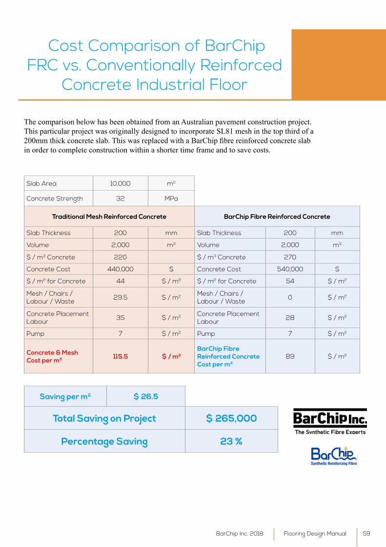
Cost Comparison of BarChip FRC vs. Conventionally Reinforced
Concrete Industrial Floor
The comparison below has been obtained from an Australian pavement construction project. This particular project was originally designed to incorporate SL81 mesh in the top third of a 200mmthickconcreteslab.ThiswasreplacedwithaBarChipfibrereinforcedconcreteslabin order to complete construction within a shorter time frame and to save costs.
Slab Area 10,000 m2
Concrete Strength 32 MPa
Traditional Mesh Reinforced Concrete BarChip Fibre Reinforced Concrete
Slab Thickness 200 mm Slab Thickness 200 mm
Volume 2,000 m3 Volume 2,000 m3
$ / m3 Concrete 220 $ / m3 Concrete 270
Concrete Cost 440,000 $ Concrete Cost 540,000 $
$ / m2 for Concrete 44 $ / m2 $ / m2 for Concrete 54 $ / m2
Mesh / Chairs / Labour / Waste 29.5 $ / m2 Mesh / Chairs /
Labour / Waste 0 $ / m2
Concrete Placement Labour 35 $ / m2 Concrete Placement
Labour 28 $ / m2
Pump 7 $ / m2 Pump 7 $ / m2
Concrete & Mesh Cost per m2 115.5 $ / m2
BarChip Fibre Reinforced Concrete Cost per m2
89 $ / m2
Saving per m2 $ 26.5
Total Saving on Project $ 265,000
Percentage Saving 23 %
Flooring Design ManualBarChip Inc. 2018 59

BarChip has a simple vision - revolutionise the world of concrete reinforcement. For
over 100 years the technology of concrete reinforcement has barely changed. We set out to
create a new reinforcement for the 21st century. We
created BarChip synthetic fibre reinforcement.
OUR VISIONWe believe that long term
business relationships can only be sustained by a commitment to provide the highest quality
products and services. We make sure to understand your concrete, know the
performance requirements and work with you to get the
right design and the right performance outcomes.
OUR PROCESSWhen you work with BarChip you know that your concrete
asset has been reinforced to the latest engineering
standards. It will never suffer from corrosion. It will be
cheaper and quicker to build. It will be safer and it will keep
performing throughout its entire design life.
YOUR PRODUCT
BarChip Inc.
Disclaimer: This information has been provided as a guide to performance only, for specific and supervised conditions. The user is advised to undertake their own evaluation and use the services of professionals to determine the product suitability for any particular project or application prior to commercial use. ISO 9001:2008. © BarChip Inc. 2018. BKFDG_2018_3.
Distributors are located in other regions. For contact details visit www.barchip.com.
BarChip Inc. [email protected]: +61 1300 131 158 N. America: +1 704 843 8401
EMEA: +353 (0) 1 469 3197Asia: +65 6835 7716S. America: +56 2 2703 1563Brazil: +55 19 3722 2199
www.barchip.com
Recommended