T
Carrier aggregation can tap LTE-
Advanced
he standardisation of 3GPP Long Term
Evolution has been completed in 2009
and numerous networks are in
commercial operation around the globe.
Still wireless broadband internet access,
providing IP based services to mobile users,
continues to grow rapidly worldwide. Therefore
3GPP has been working on further enhancements
of the LTE air interface in 3GPP Release 10 and
beyond. This new standard is called LTE Advance
and fulfills all requirements as set by the ITU-R for
4G. It has been acknowledged by the industry that
LTE Advanced will be the dominating 4G
Technology globally. LTE Advanced promises to
deliver peak data rates beyond a Gbps in up- and
downlink by aggregation of multiple carriers up to
100 MHz. For new fragmented spectrum it
increases flexibility, while keeping backward
compatibility to LTE networks and terminals. By
means of carrier aggregation LTE Advance can
operate in bandwidths up to 100 MHz in
contiguous or non-contiguous frequency
allocations.
Carrier aggregation can tap the full potency of LTE-
Advanced and solve the problems of spectrum
avai labi l i t y. Vendors inc luding Agi lent
Technologies, Aeroflex, Anritsu, and Spirent
Communications have recently made news with
regard to the test of LTE-Advanced carrier-
aggregation technology.
Carrier aggregation helps carriers meet wireless
uplink and downlink data-rate requirements for
data-hungry applications and services—even when
the carriers lack sufficient contiguous bandwidth to
meet demand.
In the feasibility study for LTE-Advanced, 3GPP
determined that today’s LTE (Release 8/9) could
meet most of the ITU’s 4G requirements apart from
uplink spectral efficiency and peak data rates.
These requirements are being addressed in Release
10 LTE-Advanced with the following features: wider
bandwidths, enabled by carrier aggregation; and
higher efficiency, enabled by enhanced uplink
multiple access and enhanced multiple antenna
transmission (advanced MIMO techniques).
Release 8 LTE itself is new and complex, introducing
such features as multiple channel bandwidths,
different transmission schemes for the downlink
and uplink, 2 transmission modes (FDD and TDD),
and the use of multiple antenna techniques
(MIMO). LTE-Advanced raises the bar on
performance expectations, and the new
technologies will have to co-exist and interoperate
with each other and with legacy 2G and 3G
deployments for years to come. The challenges for
the engineers who design, test, and ultimately
deploy LTE-Advanced are many.
“Carrier aggregation (CA) is one of the key features
of LTE-Advanced and is likely to be one of the
earliest deployed technologies of LTE-Advanced.
The basis of CA is to extend the maximum
transmission bandwidth to up to 100 MHz, and that
is done by aggregating up to 5 LTE carriers. When
carriers are aggregated, each carrier is referred to
as a component carrier. Two or more component
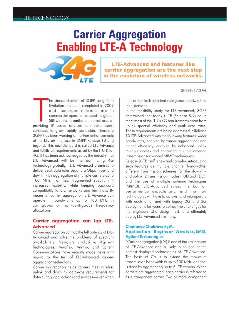
Chaitanya Chakravarty M,
Application Engineer–Wireless,EMG,
Agilent Technologies
LTE TECHNOLOGY
Carrier Aggregation Enabling LTE-A Technology
SHIKHA NAGPAL
LTE-Advanced and features like carrier aggregation are the next step in the evolution of wireless networks.
carriers are aggregated in order to support wider
transmission bandwidths up to 100 MHz to meet
peak data rate targets which are - 1Gbps in the
downlink and 500 Mbps in the uplink. Three
aggregation scenarios are possible, depending on
the spectrum availability of the operators.
Intra-band contiguous CA: is a less likely scenario
given frequency allocations today (If we look at
current FDD spectrum allocation of the US for
example, there are no allocations greater than
20MHz), however it can be common when new
spectrum bands like 3.5 GHz are allocated in the
future in various parts of the world. From
implementation perspective, this type of
aggregation is the least challenging in terms of
hardware implementation.
Intra-band Non-Contiguous CA : can be expected
in countries where spectrum allocation is non-
contiguous within a single band, when the middle
carriers are loaded with other users, or when
network sharing is considered. This mode is
postponed to Release 11
Interband Non-Contiguous CA: is the most realistic
scenario since there is no contiguous wide
spectrum to achieve the IMT-Advanced peak data
rate
3GPP initially identified 12 likely deployment
scenarios for Release 10. However, because of the
number of the scenarios and limited time, some CA
combinations were prioritized for Release 10. For
intra-band CA, the first supported carrier
bandwidths for FDD are 15 and 20 MHz in Band 1
and for TDD 10, 15 and 20 MHz bandwidths in
Band 40. For inter-band, which is limited to FDD,
bands 1 and 5 are supported for 10MHz CCs.
Other combinations will be added in a release-
independent manner.”
“Carrier Aggregation (CA) is one of the most
fundamental and critical technologies used in
cellular LTE-Advanced technology. Carrier
Aggregation increases bandwidth and thereby
increases bitrates which means higher data rate for
consumer.
Carrier Aggregation was first introduced in 3GPP
Release 10 and enhanced in 3GPP Release 11.
Carrier Aggregation enables a network operator to
combine radio channels within the same frequency
band, or across different bands, to achieve much
higher data rates and lower latency, allowing
operators to use the technology in bandwidths
wider than 20MHz. With Carrier Aggregation, LTE-
A will allow aggregation of up to five LTE carriers,
also known as component carriers (CCs), to
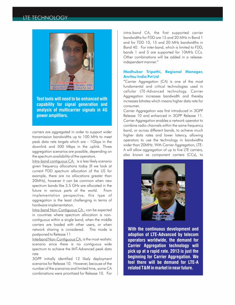
Madhukar Tripathi, Regional Manager,
Anritsu India Pvt Ltd
LTE TECHNOLOGY
Chaitanya Chakravarty MApplication Engineer –Wireless, EMG,
Agilent Technologies India Pvt. Ltd.
Chaitanya Chakravarty MApplication Engineer –Wireless, EMG,
Agilent Technologies India Pvt. Ltd.
Test tools will need to be enhanced with capability for signal generation and analysis of multicarrier signals in 4G power amplifiers.
Madhukar TripathiRegional Manager, Anritsu India Pvt Ltd
Madhukar TripathiRegional Manager, Anritsu India Pvt Ltd
With the continuous development and adoption of LTE-Advanced by telecom operators worldwide, the demand for Carrier Aggregation technology will pick up at a rapid rate. 2013 is just the beginning for Carrier Aggregation. We feel there will be demand for LTE-A related T&M in market in near future.
achieve a total effective bandwidth of 100MHz.
Carrier Aggregation allows 1Gpbs in the downlink
and 500 Mbps in the upload, and targets to
achieve wider bandwidth transmissions (higher
data rates), more efficient use of fragmented
spectrum, and more effective interference
management fo r con t ro l channe l s in
heterogeneous networks.”
“Carrier aggregation or channel aggregation
enables multiple LTE carriers to be used together to
provide higher data rates.To achieve these very
high data rates it is necessary to increase the
transmission bandwidths over those that can be
supported by a single carrier or channel. Carrier
aggregation is supported by both LTE’s FDD and
TDD variants. The target figures for data
throughput in the downlink is 1Gbps for 4G LTE-
Advanced. Even with the improvements in spectral
efficiency it is not possible to provide the required
headline data throughput rates within the
maximum 20MHz channel. The only way to
achieve the higher data rates is to increase the
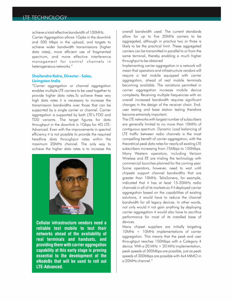
Shailendra Kalra, Director - Sales,
Livingston India
overall bandwidth used. The current standards
allow for up to five 20MHz carriers to be
aggregated, although in practice two or three is
likely to be the practical limit. These aggregated
carriers can be transmitted in parallel to or from the
same terminal, thereby enabling a much higher
throughput to be obtained
Implementing carrier aggregation in a network will
mean that operators and infrastructure vendors will
require a test mobile equipped with carrier
aggregation, ahead of real mobile terminals
becoming available. The variations permitted in
carrier aggregation increase mobile device
complexity. Receiving multiple frequencies with an
overall increased bandwidth requires significant
changes in the design of the receiver chain. End-
user testing and base station testing therefore
become extremely important.
The LTE networks with largest number of subscribers
are generally limited to no more than 10MHz of
contiguous spectrum .Dynamic Load balancing of
LTE traffic between radio channels is the most
compelling benefit of carrier aggregation, with the
theoretical peak data rates for nearly all existing LTE
subscribers increasing from 75Mbps to 150Mbps.
Many Western operators, including Verizon
Wireless and EE are trialing the technology with
commercial launches planned for the coming year.
Some operators, however, need to wait until
chipsets support channel bandwidths that are
greater than 10MHz. TeliaSonera, for example,
indicated that it has at least 15-20MHz radio
channels in all of its markets so if it deployed carrier
aggregation based on the capabilities of existing
solutions, it would have to reduce the channel
bandwidth for all legacy devices. In other words,
not only would it not gain anything by deploying
carrier aggregation it would also have to sacrifice
performance for most of its installed base of
devices.
Many chipset suppliers are initially targeting
10MHz + 10MHz implementations of carrier
aggregation. This means that the peak end user
throughput reaches 150Mbps with a Category 4
device. With a 20 MHz + 20 MHz implementation,
peak speeds of 300Mbps are possible, just as peak
speeds of 300Mbps are possible with 4x4 MIMO in
a 20MHz channel.”
LTE TECHNOLOGY
Shailendra Kalra, Director - Sales, Livingston India
Shailendra Kalra, Director - Sales, Livingston India
Cellular infrastructure vendors need a reliable test mobile to test their networks ahead of the availability of real terminals and handsets, and providing them with carrier aggregation capability at this early stage is proving essential to the development of the eNodeBs that will be used to roll out LTE-Advanced.
Testing Carrier AggregationLTE-Advanced carrier aggregation is a complex
and powerful technology enhancement. The
variances permitted in carrier aggregation increase
mobile device complexity. Receiving multiple
frequencies with an overall increased bandwidth
requires significant redesign in the receiver chain.
Primarily the increased data rate capabilities need
to be tested on all layers (physical layer, protocol
stack and E2E). It also requires verifying the correct
end user behaviour in terms of correctly responding
to RRC messages. At the base station, the major
design challenge is at the transceiver frontend,
which must support multiple band combinations.
This requires the use of highly flexible switches,
wideband power amplifiers and tuneable antenna
elements.
“With the advent of carrier aggregation, devices
have to support multiple bands and multiple
combinations of bands for aggregation which
implies more power amplifiers and different
receiver designs. Test system needs to support a
number of network test and verification features
and also needs to be able to create and run scripts
to carry out tests in the various modes supported by
the test mobile, which can be stored for later use.
This includes the need for data logging while a test
scenario is running, for later analysis of the test
results, as well as customizable tools and charts for
analysis.
Testing a mobile device that supports carrier
aggregation will focus on the capability of the
device to cope with the increased amount of data,
which will be received with two receiving chains
simultaneously thereby increasing the complexity of
the transceiver circuits. It will be necessary for
testing to take place on the physical layer, protocol
stack and E2E. Cellular infrastructure vendors need
a reliable test mobile to test their networks ahead of
the availability of real terminals and handsets, and
providing them with carrier aggregation capability
at this early stage is proving essential to the
development of the eNodeBs that will be used to
roll out LTE-Advanced.
At the base station level, the major design
challenge lies on the terminal side. Support of
higher bandwidths and aggregating carriers in
Shailendra Kalra, Director - Sales,
Livingston India
different frequency bands tremendously increases
transceiver circuit complexity, including the design
of components such as wideband power amplifiers,
highly efficient switches and tunable antenna
elements. This testing becomes significant because
service providers use component carriers or
elements from multiple operators that need to be
compatible and with equivalent standards. Further
the additional functionality provided to PHY/MAC
layer and the adaptations to the RRC layer need to
be thoroughly tested
In order to provide the equipment necessary to test
LTE carrier aggregation, Livingston has partnered
with companies like Spirent, Agilent, Rohde &
Schwarz and Anritsu.It thus has a broad offering
which includes signal generators , analyzers and
scanners for performing physical layer tests on base
stations, as well as base station emulators for
physical layer and protocol tests for all kind of
wireless devices and chipsets.
“Carrier aggregation has several implications for
the RF characteristics. From RF perspective, intra-
band contiguous aggregated carriers have similar
properties as a corresponding wider carrier being
transmitted and received. However the output
power dynamics are impacted by the UE
architecture, which may be based on single or
multiple PAs. When considering the PA
configuration, one must take into account
additional back-off requirements that may exist due
to combination of carrier aggregation and the
other new UL features such as clustering introduced
in Release 10 which requires more stringent
linearity requirements on the PA than was the case
for Release 8/9. When using multiple component
carriers, the maximum output power of a UE must
be reduced in order to keep the amplifier in the
linear region. UE maximum output power is a
critical parameter that limits the UL coverage of a
network so reduced transmission power means
limited UL coverage. So for a UE, increasing the
bandwidth does not always result in an increase of
the user performance. Because of that, use of
multiple uplink carriers needs to be an option that is
only used for cases where UEs are not at the cell
edge, thus ensuring that the cell-edge data rate is
Chaitanya Chakravarty M,
Application Engineer–Wireless, EMG,
Agilent Technologies
LTE TECHNOLOGY
not reduced. The other test challenge is to analyze
the multiple transmit and receive chains
simultaneously. When an eNB transmits multiple
component carriers to a UE, the multiple
component carriers must arrive at the receiver at
the same time, time alignment error of 1.3 µs for
inter-band and 130 ns for intra-band are specified
for downlink. This requires simultaneous
demodulation of the multiple component carriers.
Higher order MIMO will increase the need for
simultaneous transceivers in a manner similar to
carrier aggregation. However, MIMO has an
additional challenge in that the number of
antennas will multiply, and the MIMO antennas will
have to be de-correlated. It will be especially
difficult to design multiband, MIMO antennas with
good de-correlation to operate in the small space
of a 4G UE. Conducted testing of higher order
MIMO terminals will no longer be usable for
predicting actual radiated performance in an
operational network. The introduction of clustered
SC-FDMA in the uplink allows frequency selective
scheduling within a component carrier for better
link performance, and the PUCCH and PUSCH can
be scheduled together to reduce latency. However,
clustered SC-FDMA increases peak to average
power ratio (PAR) by several dB, adding to
transmitter linearity issues. Simultaneous PUCCH
and PUSCH also increase PAR. Both features create
multi-carrier signals within the channel bandwidth
and increase the opportunity for in-channel and
adjacent channel spur generation. Test tools will
need to be enhanced with capability for signal
generation and analysis of multicarrier signals in
4G power amplifiers.
The Solutions from Agilent’s Side:
1. Agilent LTE-Advanced library as a part of ADS,
The industry’s first commercial design support for
the physical layer of 3GPP Release 10. It enables
system and algorithm developers to explore their
new designs against the new standard. They can
directly download test vectors to instruments for
early and continuous hardware validation,
accelerating design maturity. And the MIMO
Channel Builder and Digital Pre-distortion
applications also support Release 10.
2. LTE-Advanced signal generation and signal
analysis tools, enabling design engineers to start
t e s t i ng LTE -Advanced ph y s i ca l l a y e r
implementations today. They include the flexible
and easy-to-use Signal Studio that runs on all the
Agilent signal generation hardware platforms
including the PXB and the 89600B vector signal
analysis (VSA) software that runs on signal
analyzers, scopes and logic analyzers.
“Substantial growth of mobile data usages will
demand for right testing tools for LTE-A/ Carrier
Aggregation. We see extensive test challenges in
LTE-A device design & testing. Carrier Aggregation
will also play a major role in interference
management in LTE-A using SON systems. New
spectrum band standardization will need right T&M
for LTE-A success. Heterogeneous network creates
more complex situations as far as testing is
concerned.”
Anritsu offers various Test solutions for LTE
Advanced network& devices. LTE A networks are
tested at various stages. This includes UE (peak
data rates-UL/DL, Protocol Conformance Test, RF
Conformance test), Handover test, Base Station &
other components of mobile network.
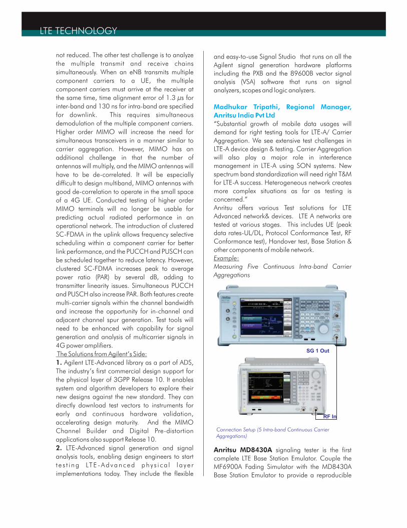
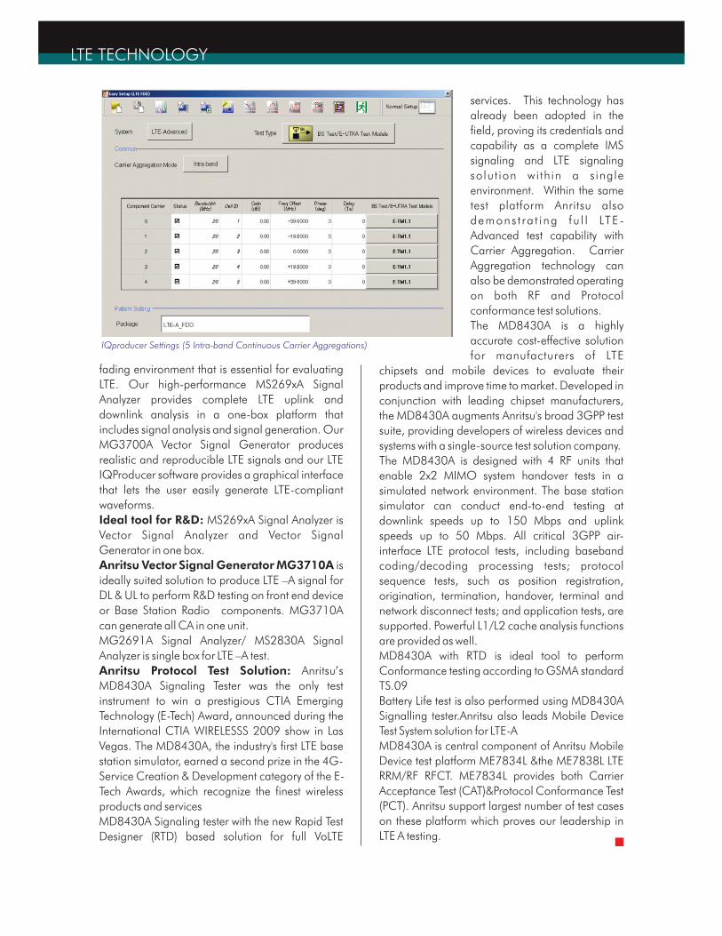
Example:
Measuring Five Continuous Intra-band Carrier
Aggregations
Anritsu MD8430A signaling tester is the first
complete LTE Base Station Emulator. Couple the
MF6900A Fading Simulator with the MD8430A
Base Station Emulator to provide a reproducible
Madhukar Tripathi, Regional Manager,
Anritsu India Pvt Ltd
LTE TECHNOLOGY
SG 1 Out
RF In
Connection Setup (5 Intra-band Continuous Carrier Aggregations)
fading environment that is essential for evaluating
LTE. Our high-performance MS269xA Signal
Analyzer provides complete LTE uplink and
downlink analysis in a one-box platform that
includes signal analysis and signal generation. Our
MG3700A Vector Signal Generator produces
realistic and reproducible LTE signals and our LTE
IQProducer software provides a graphical interface
that lets the user easily generate LTE-compliant
waveforms.
Ideal tool for R&D: MS269xA Signal Analyzer is
Vector Signal Analyzer and Vector Signal
Generator in one box.
Anritsu Vector Signal Generator MG3710A is
ideally suited solution to produce LTE –A signal for
DL & UL to perform R&D testing on front end device
or Base Station Radio components. MG3710A
can generate all CA in one unit.
MG2691A Signal Analyzer/ MS2830A Signal
Analyzer is single box for LTE –A test.
Anritsu Protocol Test Solution: Anritsu’s
MD8430A Signaling Tester was the only test
instrument to win a prestigious CTIA Emerging
Technology (E-Tech) Award, announced during the
International CTIA WIRELESSS 2009 show in Las
Vegas. The MD8430A, the industry's first LTE base
station simulator, earned a second prize in the 4G-
Service Creation & Development category of the E-
Tech Awards, which recognize the finest wireless
products and services
MD8430A Signaling tester with the new Rapid Test
Designer (RTD) based solution for full VoLTE
services. This technology has
already been adopted in the
field, proving its credentials and
capability as a complete IMS
signaling and LTE signaling
solut ion within a single
environment. Within the same
test platform Anritsu also
demons t ra t ing fu l l LTE -
Advanced test capability with
Carrier Aggregation. Carrier
Aggregation technology can
also be demonstrated operating
on both RF and Protocol
conformance test solutions.
The MD8430A is a highly
accurate cost-effective solution
for manufacturers of LTE
chipsets and mobile devices to evaluate their
products and improve time to market. Developed in
conjunction with leading chipset manufacturers,
the MD8430A augments Anritsu's broad 3GPP test
suite, providing developers of wireless devices and
systems with a single-source test solution company.
The MD8430A is designed with 4 RF units that
enable 2x2 MIMO system handover tests in a
simulated network environment. The base station
simulator can conduct end-to-end testing at
downlink speeds up to 150 Mbps and uplink
speeds up to 50 Mbps. All critical 3GPP air-
interface LTE protocol tests, including baseband
coding/decoding processing tests; protocol
sequence tests, such as position registration,
origination, termination, handover, terminal and
network disconnect tests; and application tests, are
supported. Powerful L1/L2 cache analysis functions
are provided as well.
MD8430A with RTD is ideal tool to perform
Conformance testing according to GSMA standard
TS.09
Battery Life test is also performed using MD8430A
Signalling tester.Anritsu also leads Mobile Device
Test System solution for LTE-A
MD8430A is central component of Anritsu Mobile
Device test platform ME7834L &the ME7838L LTE
RRM/RF RFCT. ME7834L provides both Carrier
Acceptance Test (CAT)&Protocol Conformance Test
(PCT). Anritsu support largest number of test cases
on these platform which proves our leadership in
LTE A testing.
LTE TECHNOLOGY
IQproducer Settings (5 Intra-band Continuous Carrier Aggregations)
Recommended