AREA7,000±sq. ft.
CATHERINE STREET
S52°26'14"E50.00'
S37°33'46"W
140.00'
S52°26'14"E 50.00'
S37°33'46"W
140.00'
12.1±'
12.2±'
8.1±'
1.1±'8.2±'
7.0±'
6.8±'
20.2±'
19.9'
20.2±'
20.2±'
20.2±'
LOT 8 LOT 7
LOT 12LOT 13
LOT 6
SIDEWALK
WALK
DRIVEWAY
GARAGE
EDGE OF PAVEMENT
RETAINING
WALL
STAIRS
3.1±'
3.1±'
1.4±'
4.7±'
4.7±'
24.0±'
17.0±'
9.3±'
9.3±'
UL
UL
UL
UL
UL
UL
MIN. SIDE Y
EXISTING S
AREA OF S
DRIVEWAY AGREEMENT
Bk.796, Pg. 29.
ENTRANCE
LANDING
@ Eave3.7' +/-
Additio
nExis
ting
Two S
tory
Wood F
ram
ed S
truc
ture
MAGN
ETIC
20' - 0" Front Yard
Side Yard
15' - 0"
Side Yard
15' - 0"
30' - 0" Rear Yard
ZONING DATA
Zoning District MROccupancy Classification: Single FamilyConstruction Type: NFPA Type VANumber of Stories: 2Building Height: 27'-0"Square Footage Existing: 905 sfSquare Footage Addition: 252 sfNumber of Bedrooms Existing: 3Number of Bedrooms New: 4
Lot RequirementsItem Required ActualLot Area 10,000 sf *7,000 sfWidth 80 ft *50 ftDepth 100 ft *140 ftCoverage 40% 20%
Front Yard 20 ft 17 ftSide Yard 15 ft *3.7 ftRear Yard 30 ft 72 ftAccesory Side 15 ft 3.1 ftAccessory Rear 30 ft 1.4 ft
Building RequirementsItem Required ActualMax Height Stories 6 2Max Height Feet 75 ft 27 ftMin Floor Area 660 sf 1157 sf
* Items approved by the Town of Scotia Zoning Board of Appeals dated 4/26/2010.
Site information based upon a survey provided by Stephen E. Lamb, P.E., L.S.for Peter and Cinthia Frisoni dated 3/10/2010 as recorded in the Book ofDeeds 1717, page 894
Site plan complies with the Area Variance as approved by the Town of ScotiaZoning Board of Appeals dated 4/26/2010.
6
D
C
B
A
3
54321
654321
REVISIONS:
Architects, P.C.
Designed By:
CHARETTE ASSOCIATES
Notice:The drawings, plans, specifications and designs contained herein areand shall remain the exclusive property of Charette AssociatesArchitects, P.C., and cannot be altered, copied, duplicated or useddirectly or indirectly in whole or in part except with the express writtenpermission of Charette Associates Architects, P.C. Copyright 2010
PROJECT
DESIGNED
DRAWN
DRAWING TITLE
SEAL
CHECKED
APPROVED
DATE
PROJECT NO.
SCALE
DRAWING NO.
Gansevoort, New YorkPhone (518) 583-6855 Fax (518) 581-0530
The information contained within is protected by Copyright. The Architectauthorizes the Owner to reproduce and use these Copywrited drawings only foruse related to construction of the Project. The Owner shall not provide thesedocuments to any other person except to those who need to know the contentin order to perform services or construction solely and exclusively for theProject, or their consultants and contractors who shall be bound with similarrestrictions on the use of these documents.
No party, without written permission from the Architect, shall modify thesedocuments.
210 Catherine StreetScotia, New York
As indicated
Frisoni Residence Addition
Site Plan
C-101
1001LA
MP/LA
LA
-
3/16/2010SCALE: 1" = 10'-0"
Site PlanA1

UP
C1
A-301
C1
A-301
A1
A-301
A1
A-301
11
20
' - 0
"
20' - 0"
A3
A-301
A3
A-301
9' - 0" 9' - 8"
8" 15' - 6"
3' - 2"
8"
T/Ftg -8' - 3 3/4"B/Ftg -8' - 11 3/4"
T/Ftg -8' - 3 3/4"B/Ftg -8' - 11 3/4"
T/Ftg -8' - 3 3/4"B/Ftg -8' - 11 3/4"
T/Ftg -8' - 3 3/4"B/Ftg -8' - 11 3/4"
2' - 6" +/-
1" Rat Slab on 6 Mil Poly VaporBarrier on 6" Well CompactedGranular Fill or Crushed Stone.
4' -
8"
7' -
8"
7' -
8"
T/Conc -10 1/4"
T/Conc -10 1/4"
T/Conc -10 1/4"
Unexcavated
1
1
1
1
1A
8"x16" Concrete Footing
8"x16" Concrete Footing
A
22
8' - 8" 10' - 0"
36" x 36" x 12" Conc Ftg.
PIPE4SCH40
A-101D4
T/Ftg -5' - 5"B/Ftg -6' - 1"
T/Ftg -5' - 5"B/Ftg -6' - 1"
T/Conc -10 1/4"
(2) 1
3/4
x 9
1/4
1.9E
ML B
eam
2x8 FL JST @ 16" OC 2x8 FL JST @ 16" OC
(2) 1
3/4
x 9
1/4
1.9E
ML B
eam
3' - 4 1/4"
8' -
3"
Doub
le J
ois
t
DoubleJoist
1' -
1 3
/8"
R @
7 23/3
2"
12
36" x 36" x 12" Conc Ftg.PIPE4SCH40
SD
Hard-wired SmokeDetectors (typ)
3' - 6"Remove Existing Damaged
CMU. Replace with New andRe-point Damaged Areas as
Required.
D1D1
D9D9
D3
D9D1
16' - 2" +/- 3' - 6"
D5
D5
3' - 0" +/- 3' - 6" D5
GENERAL NOTES
Federal Copyright Law protects these plans. Reproduction or modification ofthese plans without the written consent of Charette Associates Architects,P.C. (CAA), is strictly prohibited.
1. Construction shall conform to the latest edition of the ResidentialCode of New York State (RCNYS) and the Energy ConservationConstruction Code of New York State.
2. Construction documents for this work have been prepared inaccordance with generally accepted architectural and engineeringpractice to meet minimum requirements of the latest edition of theRCNYS.
3. In the event of conflict between pertinent codes and regulations andreferenced standards of these drawings and specifications, themore stringent provisions shall govern.
4. Contractor shall be responsible for all materials, constructionmethods, craftsmanship, procedures and conditions (including safety).
5. Contractor shall verify all existing conditions, requirements, notes,and dimensions shown on Drawings or noted in Specifications. Anyvariances within drawings and Specifications, or with conditionsencountered at job site, shall be reported in writing to the Architectbefore commencement of any work affected by such variance.
6. Contractor shall rigidly adhere to all laws, codes, and ordinances,which apply to this work. Contractor shall notify and receive writtenclarification from the Architect of any variations between contractdocuments and governing regulations.
7. The Contractor shall make no structural changes without writtenapproval of the Architect.
8. The Architect assumes no responsibility for constructionconformance, means, methods, techniques or procedures of on-sitework relating to the construction plans.
9. The Architect assumes no responsibility for unauthorized deviationsfrom the drawings.
10. All manufactured materials, components, fasteners, assemblers, etc.,shall be handled and installed in accordance with manufacturer'sinstructions and provisions of applicable industry standards. Wherespecific manufactured products are called for, generic equals thatmeet applicable standards and specifications may be used.
11. All materials used to be selected and installed in accordance withstate, federal, national and local codes and installed in accordancewith manufacturers recommended installation procedures.
12. Construction loads shall not overload structure nor shall they be inexcess of design loadings indicated herein.
13. Drawings and specifications are intended to provide the basis forthe proper completion of the Project suitable for the intended useof the Owner.
14. Items not expressly set forth but which are reasonably implied ornecessary for the proper performance of this work shall be included.
15. Inspect substrates and report unsatisfactory conditions in writing.Do not proceed until unsatisfactory conditions have been corrected.
16. All dimensions are framing to framing of lumber or to face ofconcrete unless noted otherwise.
17. Do not scale drawings. Use dimensions as indicated for all locations.
18. Deviations from these drawings which are not performed with priorwritten consent from the architect are solely at the contractor'srisk and he shall accept fully liability for same.
FOUNDATIONS
GENERAL:
Contractor to notify CAA if site conditions such as adverse ground water or soil conditions warrant modificationsto the engineering design of the foundation.Footings may by poured neat against sides of excavations only if sloughing or raveling does not occur.Contractor shall be responsible for support of all temporary embankments and excavations.Backfill shall not be placed against basement foundation walls until:
a. Concrete or masonry grout has reached sufficient strength to resist damage.b. Structural floor framing (including plywood sub-floor) required to stabilize walls is complete and
fully nailed and anchored or sufficient bracing is applied to prevent wall damage.
STRUCTURAL BACKFILL:
Structural backfill of well graded, well drained, sand and gravel or crusher run stone shall be placed in 6-inchmaximum lifts and compacted to a minimum density of 95% (under slabs-on-grade and building structure) and 90%(elsewhere) of maximum density at maximum moisture content as determined by ASTM D698.Backfill shall be free of excessive vegetation, debris or other deleterious materials and contain no particles largerthan 3-inches in diameter and no more than 10% passing the #200 sieve.
FOOTINGS:Footings shall be placed at a minimum depth of 48-inches below adjacent finished grade unless otherwise specifiedon the Contract Documents.Final 3-inches of excavation shall be removed by hand tool operations in order to assure bearing surfaces.Footing shall be founded on firm, undisturbed, native soils free of frost and loose material. Footing may bear onproperly engineered backfill provided settlement and/or consolidation tests performed indicate anticipatedsettlement will not exceed that allowed for the proposed structure.Bottom surface of footings shall not slope more than 1.0 vertical to 10.0 horizontal, except as shown otherwise ofdrawings.No excavation shall be made lower and closer to any footing than 1.0 vertical to 3.0 horizontal, except as shown ondrawings.Footings and slabs-on-grade shall not be placed on muddy or frozen ground.Foundation and footing design is based upon an allowable soil bearing pressure of 3000 psf without excessivedifferential settlement.Center all footings under walls, columns or grid lines unless otherwise noted on plans.Contractor to provide field density tests on compacted fill under footings and interior slabs-on-grade.
1.
2.3.4.
1.
2.
1.
2.3.
4.
5.
6.7.
8.9.
NOTE: BOTTOM OF ALL FOOTINGS TO BEAR ON UNDISTURBED SOIL.
PIPE COL.
CONC. SLAB W/FIBROUS REINFORCINGON 6 MIL. POLYVAPOR BARRIER
CONC.FOOTING
#4 BARS, EA. WAY
9"X9"X1/2" BASEPLATE W/ (2)5/8" DIA. x 8"ANCHOR BOLTS
3' - 0"
1' -
0"
6
D
C
B
A
3
54321
654321
REVISIONS:
Architects, P.C.
Designed By:
CHARETTE ASSOCIATES
Notice:The drawings, plans, specifications and designs contained herein areand shall remain the exclusive property of Charette AssociatesArchitects, P.C., and cannot be altered, copied, duplicated or useddirectly or indirectly in whole or in part except with the express writtenpermission of Charette Associates Architects, P.C. Copyright 2010
PROJECT
DESIGNED
DRAWN
DRAWING TITLE
SEAL
CHECKED
APPROVED
DATE
PROJECT NO.
SCALE
DRAWING NO.
Gansevoort, New YorkPhone (518) 583-6855 Fax (518) 581-0530
The information contained within is protected by Copyright. The Architectauthorizes the Owner to reproduce and use these Copywrited drawings only foruse related to construction of the Project. The Owner shall not provide thesedocuments to any other person except to those who need to know the contentin order to perform services or construction solely and exclusively for theProject, or their consultants and contractors who shall be bound with similarrestrictions on the use of these documents.
No party, without written permission from the Architect, shall modify thesedocuments.
210 Catherine StreetScotia, New York
As indicated
Frisoni Residence Addition
Basement Plan
A-101
1001LA
MP/LA
LA
-
3/16/2010SCALE: 1/4" = 1'-0"
BasementA4SCALE: 1/4" = 1'-0"
Basement RemovalsA1
Demolition Keynotes
D1 Remove Foundation Wall and Footings. Fill void as required.D2 Remove Wall Where IndicatedD3 Remove Existing Door, Frame And TrimD4 Remove Existing Window, Frame And Trim.D5 Remove Wall As Required For New OpeningD7 Remove plumbing fixtures. Cap abandoned lines.D8 Remove floor finishesD9 Remove stairs and railingsD10 Remove window and sill framing. Widen opening as required.D11 Ceiling to be removedD12 Remove roofing shingles and building paperD16 Remove roofing inclusive of roof rafters and associated framingD17 Remove sheathing/planks as required to install ridge ventD18 Remove siding and sheathingD19 Wood flooring/framing to be removedD21 Remove Sheathing to permit a 36"x48" Attic Opening at Addition
Wall ScheduleType Fire Description1 - 8" Poured Reinforced Concrete Foundation Wall1A - 8" CMU Infill2 - 2x6 Wood Studs @ 16" o.c. w/ 5/8" Plywood Sheathing. 1/2" GWB
and 6" R-19 Batt Insul w/ Air Infiltration and Vapor Barrier3 - 2x4 Wood Studs @ 16" o.c. w/ 1/2" GWB Ea Side4 2x Furring on existing Studs with 1/2" GWB one side.
SCALE: 1" = 1'-0"
Footing DetailD4
UP
UP
DN
REF
.
DW
D9 D19
D2
D3
D3
D3 D3
D4
D2
D2D2
D2
D9
D8D8
D7
D16
D3D11
Dining Living
Kitchen
Porch
D4
D5
C1
A-301
C1
A-301
A1
A-301
A1
A-301
11
Kitchen
103
Mud
105
Toilet
106
Living
102
Dining
101
Stair
107
Nook
104
Bench
Built-inBanquette
CoveredPorch
Additio
n20
' - 0
"Exis
ting
Cons
truc
tion
to R
em
ain
29' -
3"
Addition20' - 0" 16' - 3"
3' -
11
1/2"
3' -
6 1
/4"
x 6
'-8" H.
4' -
0"
1' -
5"
6' -
10
3/4
"3' -
2 1
/2"
4' -
5 1
/2"
9' - 1" 3 1/2" 9' - 8 1/2"
1 1/2"
10' - 3 1/2" 3 1/2" 4' - 11" 3 1/2"3' - 5"
1' - 1"
15' -
5 1
/4"
2' -
7 1
/2"
3' - 1" 4' - 5" 2' - 7 1/2"
A3
A-301
A3
A-301
A
222
4
3
3
3
3
2
23
3
2' -
2"
6' -
2"
2' - 0" 3' - 0" 3' - 0" 2' - 0"
2' -
2"
105
106
W1 W1
W1
W1
W1
W1
W1
W3
Furr Out Existing 2x4 Wall
Range w/ Hood above -Vent to Exterior
Cabinets & Countertop
Replace Sink
(2) 2x8 H
dr
Solid Blocking toFoundation (typ)
6x6 PT Wd Post
3'-0" High Wood Handrail (typ)
Fan/Light - Vent to Exterior
2x8 FL JST@ 16" OC
4" Conc. Slab on Grade w/ 6 Mil PolyVapor Barrier on 6" Well CompactedGranular Fill or Crushed Stone. Pitch awayfrom Door.
Lowered Countertop
1' - 4 1/2"
Align
Align
Alig
n
R @
7 23/3
2"
12
(4) 2x12
Beam
(2) 2x10 Beam
Dble Joist
SD
2x8
Raf
ters
@ 1
6" O
C
2x8
Hip
Raft
er
2x8 Hip Rafter
Roof Overhang Above
Hard-wired SmokeDetectors (typ)
107
(4) 2x8HDR Flush
(4) 2x8 HDR
(2) 2x8 H
dr
W2
Raise Headroom to 6'-8" over Stairs & Provide Header
(2) 2x10 Header
2x8
Raf
ters
@ 1
6" O
C
6
D
C
B
A
3
54321
654321
REVISIONS:
Architects, P.C.
Designed By:
CHARETTE ASSOCIATES
Notice:The drawings, plans, specifications and designs contained herein areand shall remain the exclusive property of Charette AssociatesArchitects, P.C., and cannot be altered, copied, duplicated or useddirectly or indirectly in whole or in part except with the express writtenpermission of Charette Associates Architects, P.C. Copyright 2010
PROJECT
DESIGNED
DRAWN
DRAWING TITLE
SEAL
CHECKED
APPROVED
DATE
PROJECT NO.
SCALE
DRAWING NO.
Gansevoort, New YorkPhone (518) 583-6855 Fax (518) 581-0530
The information contained within is protected by Copyright. The Architectauthorizes the Owner to reproduce and use these Copywrited drawings only foruse related to construction of the Project. The Owner shall not provide thesedocuments to any other person except to those who need to know the contentin order to perform services or construction solely and exclusively for theProject, or their consultants and contractors who shall be bound with similarrestrictions on the use of these documents.
No party, without written permission from the Architect, shall modify thesedocuments.
210 Catherine StreetScotia, New York
1/4" = 1'-0"
Frisoni Residence Addition
First Floor Plan
A-102
1001LA
MP/LA
LA
-
3/16/2010SCALE: 1/4" = 1'-0"
First Floor RemovalsA1 SCALE: 1/4" = 1'-0"
First FloorA4
Demolition Keynotes
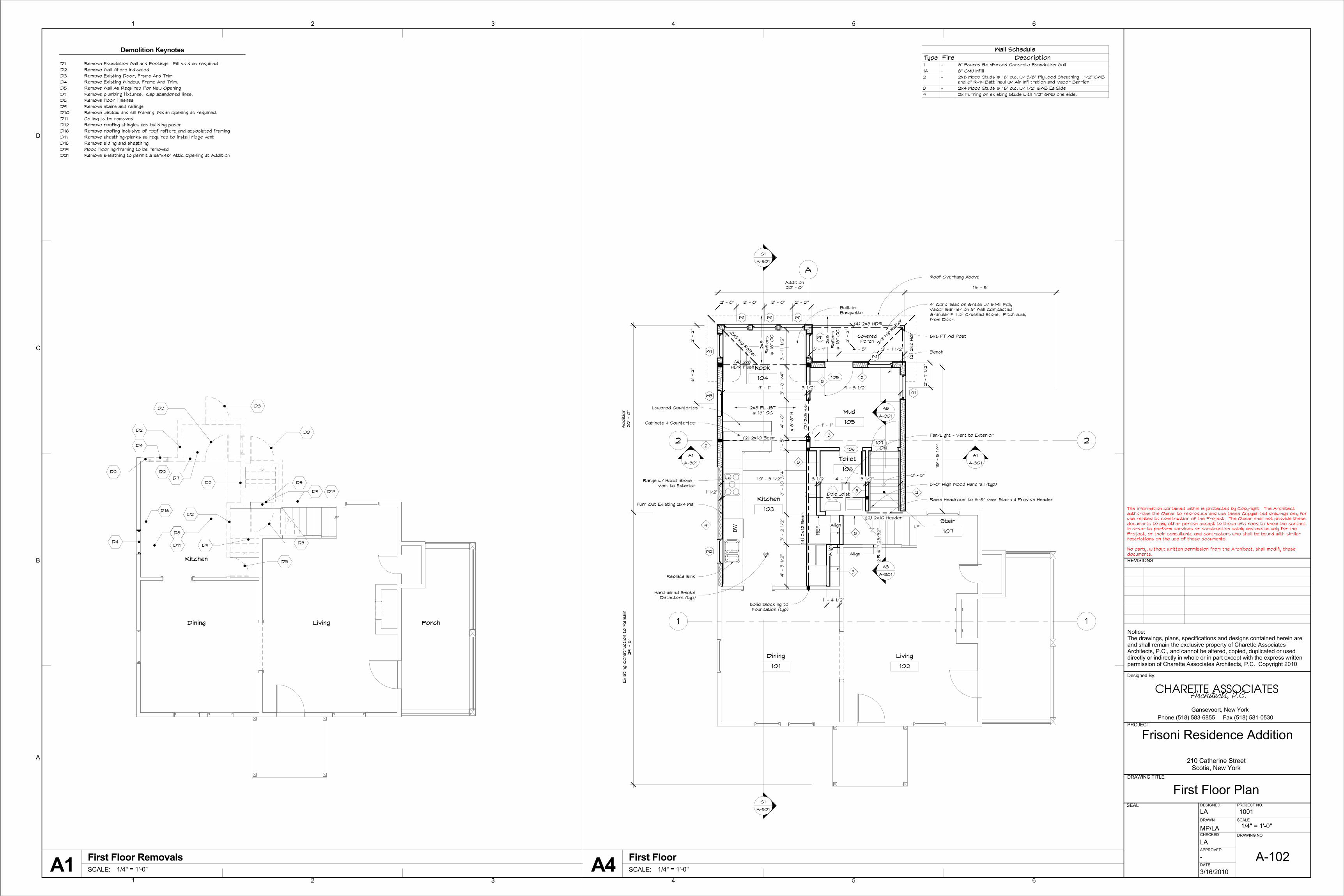
D1 Remove Foundation Wall and Footings. Fill void as required.D2 Remove Wall Where IndicatedD3 Remove Existing Door, Frame And TrimD4 Remove Existing Window, Frame And Trim.D5 Remove Wall As Required For New OpeningD7 Remove plumbing fixtures. Cap abandoned lines.D8 Remove floor finishesD9 Remove stairs and railingsD10 Remove window and sill framing. Widen opening as required.D11 Ceiling to be removedD12 Remove roofing shingles and building paperD16 Remove roofing inclusive of roof rafters and associated framingD17 Remove sheathing/planks as required to install ridge ventD18 Remove siding and sheathingD19 Wood flooring/framing to be removedD21 Remove Sheathing to permit a 36"x48" Attic Opening at Addition
Wall ScheduleType Fire Description1 - 8" Poured Reinforced Concrete Foundation Wall1A - 8" CMU Infill2 - 2x6 Wood Studs @ 16" o.c. w/ 5/8" Plywood Sheathing. 1/2" GWB
and 6" R-19 Batt Insul w/ Air Infiltration and Vapor Barrier3 - 2x4 Wood Studs @ 16" o.c. w/ 1/2" GWB Ea Side4 2x Furring on existing Studs with 1/2" GWB one side.
DN
DN
DN
DN
DN
Bath
Closet
Bedroom #3Linen
Closet Closet
Bedroom #2Bedroom #1
Hall
Roof Below
Roof Below
D16
D103' - 2"
C1
A-301
C1
A-301
A1
A-301
A1
A-301
Bonus
206
Bath
204
Closet
201A
Bedroom #3
205
Linen
203A
Closet
205A
Closet
202A
Bedroom #2
202
Bedroom #1
201
Hall
203
Additio
n20
' - 0
"Exis
ting
Cons
truc
tion
to R
em
ain
29' -
3"
Addition20' - 0" 8' - 2"
Roof Below
Roof Below
Roof Below
7' -
11
3/4
"2' -
9"
3' - 2 3/8" 3' - 5" 3' - 4 3/4" 3' - 4 3/4" 3' - 5" 3' - 2 3/8"
4' -
11
1/2"
A3
A-301
A3
A-301
A
222
32
2
3' - 3"
W5
W4
206
W4W4 W4
W6
W5
W4
Notes:1. Bathroom #207 to be provided as Phase 2work. Phase 1 work shall include providing roughplumbing for fixtures. Cap all lines leading toBathroom #207 and conceal in floor or wall.2. Attic access at attition to be provided fromexisting attic space.
36" High Wood Handrail
(2) 2X10 Hdr
2x8 RAFTERS @ 16" OCSD
SD
SD SD
SD
2x8
RAFTER
S@
16" O
C
2x8 Hip Rafter
2x8
Hip
Raft
er
2x10
Rid
ge B
oar
d
Roof OverhangAbove
Hard-wired SmokeDetectors (typ)
Hard-wired SmokeDetectors (typ)
6
D
C
B
A
3
54321
654321
REVISIONS:
Architects, P.C.
Designed By:
CHARETTE ASSOCIATES
Notice:The drawings, plans, specifications and designs contained herein areand shall remain the exclusive property of Charette AssociatesArchitects, P.C., and cannot be altered, copied, duplicated or useddirectly or indirectly in whole or in part except with the express writtenpermission of Charette Associates Architects, P.C. Copyright 2010
PROJECT
DESIGNED
DRAWN
DRAWING TITLE
SEAL
CHECKED
APPROVED
DATE
PROJECT NO.
SCALE
DRAWING NO.
Gansevoort, New YorkPhone (518) 583-6855 Fax (518) 581-0530
The information contained within is protected by Copyright. The Architectauthorizes the Owner to reproduce and use these Copywrited drawings only foruse related to construction of the Project. The Owner shall not provide thesedocuments to any other person except to those who need to know the contentin order to perform services or construction solely and exclusively for theProject, or their consultants and contractors who shall be bound with similarrestrictions on the use of these documents.
No party, without written permission from the Architect, shall modify thesedocuments.
210 Catherine StreetScotia, New York
1/4" = 1'-0"
Frisoni Residence Addition
Second Floor Plan
A-103
1001LA
MP/LA
LA
-
3/16/2010SCALE: 1/4" = 1'-0"
Second Floor Removal PlanA1 SCALE: 1/4" = 1'-0"
Second Floor PlanA4
Demolition Keynotes
D1 Remove Foundation Wall and Footings. Fill void as required.D2 Remove Wall Where IndicatedD3 Remove Existing Door, Frame And TrimD4 Remove Existing Window, Frame And Trim.D5 Remove Wall As Required For New OpeningD7 Remove plumbing fixtures. Cap abandoned lines.D8 Remove floor finishesD9 Remove stairs and railingsD10 Remove window and sill framing. Widen opening as required.D11 Ceiling to be removedD12 Remove roofing shingles and building paperD16 Remove roofing inclusive of roof rafters and associated framingD17 Remove sheathing/planks as required to install ridge ventD18 Remove siding and sheathingD19 Wood flooring/framing to be removedD21 Remove Sheathing to permit a 36"x48" Attic Opening at Addition
Wall ScheduleType Fire Description1 - 8" Poured Reinforced Concrete Foundation Wall1A - 8" CMU Infill2 - 2x6 Wood Studs @ 16" o.c. w/ 5/8" Plywood Sheathing. 1/2" GWB
and 6" R-19 Batt Insul w/ Air Infiltration and Vapor Barrier3 - 2x4 Wood Studs @ 16" o.c. w/ 1/2" GWB Ea Side4 2x Furring on existing Studs with 1/2" GWB one side.

D17
D17
D12
D12
D12
D12
D12
D12
D12 D12
ExistingRoof toRemain
ExistingRoof toRemain
D18
D17
D21
C1
A-301
C1
A-301
A1
A-301
A1
A-301
A3
A-301
A3
A-301
D4
A-104VTR (locate in Field)
Ice and Water Shield to24" from Outside Wall andat Valley (typ)
9" /
12"
9" / 12" 9" / 12"
9" /
12"
9" / 12"
9" /
12"
9" / 12"
Align Addition Roofto Existing Hip
Valle
y
Ridge Vent (typ)
Ridge Vent (typ)
D4
A-104
Roof Belowto Remain
Roof Belowto Remain
Roof Below
2' -
0"
2' - 0"
2' - 0"2' - 0"
2' -
0"
2' - 0"
2' -
0"
Ice and Water Shield to24" from Outside Wall and
at Valley (typ)
30 Year FGShingles (typ)
30 Year FGShingles (typ)
30 Year FGShingles (typ)
Face of Building Below
Face of Building Below
Face of Building Below
Face of Building Below
5" /
12"
5" / 12"5" / 12"
Ove
rhan
g (
t yp)
1' -
1"
Overhang (typ)1' - 1"
Continuous metal ridgevent w/ louvers on theunderside
Nail or screw ridge toroofing
Sheathing
Rafters (see plans)
Ridge Board
40 year FGArchitectural Shingles
1" to 1-1/2"
6
D
C
B
A
3
54321
654321
REVISIONS:
Architects, P.C.
Designed By:
CHARETTE ASSOCIATES
Notice:The drawings, plans, specifications and designs contained herein areand shall remain the exclusive property of Charette AssociatesArchitects, P.C., and cannot be altered, copied, duplicated or useddirectly or indirectly in whole or in part except with the express writtenpermission of Charette Associates Architects, P.C. Copyright 2010
PROJECT
DESIGNED
DRAWN
DRAWING TITLE
SEAL
CHECKED
APPROVED
DATE
PROJECT NO.
SCALE
DRAWING NO.
Gansevoort, New YorkPhone (518) 583-6855 Fax (518) 581-0530
The information contained within is protected by Copyright. The Architectauthorizes the Owner to reproduce and use these Copywrited drawings only foruse related to construction of the Project. The Owner shall not provide thesedocuments to any other person except to those who need to know the contentin order to perform services or construction solely and exclusively for theProject, or their consultants and contractors who shall be bound with similarrestrictions on the use of these documents.
No party, without written permission from the Architect, shall modify thesedocuments.
210 Catherine StreetScotia, New York
As indicated
Frisoni Residence Addition
Roof Plan
A-104
1001LA
MP/LA
LA
-
3/16/2010SCALE: 1/4" = 1'-0"
Roof Removal PlanA1 SCALE: 1/4" = 1'-0"
Roof PlanA4
Demolition Keynotes
D1 Remove Foundation Wall and Footings. Fill void as required.D2 Remove Wall Where IndicatedD3 Remove Existing Door, Frame And TrimD4 Remove Existing Window, Frame And Trim.D5 Remove Wall As Required For New OpeningD7 Remove plumbing fixtures. Cap abandoned lines.D8 Remove floor finishesD9 Remove stairs and railingsD10 Remove window and sill framing. Widen opening as required.D11 Ceiling to be removedD12 Remove roofing shingles and building paperD16 Remove roofing inclusive of roof rafters and associated framingD17 Remove sheathing/planks as required to install ridge ventD18 Remove siding and sheathingD19 Wood flooring/framing to be removedD21 Remove Sheathing to permit a 36"x48" Attic Opening at Addition
SCALE: 1 1/2" = 1'-0"
Ridge Vent DetailD4
REF
.
DW
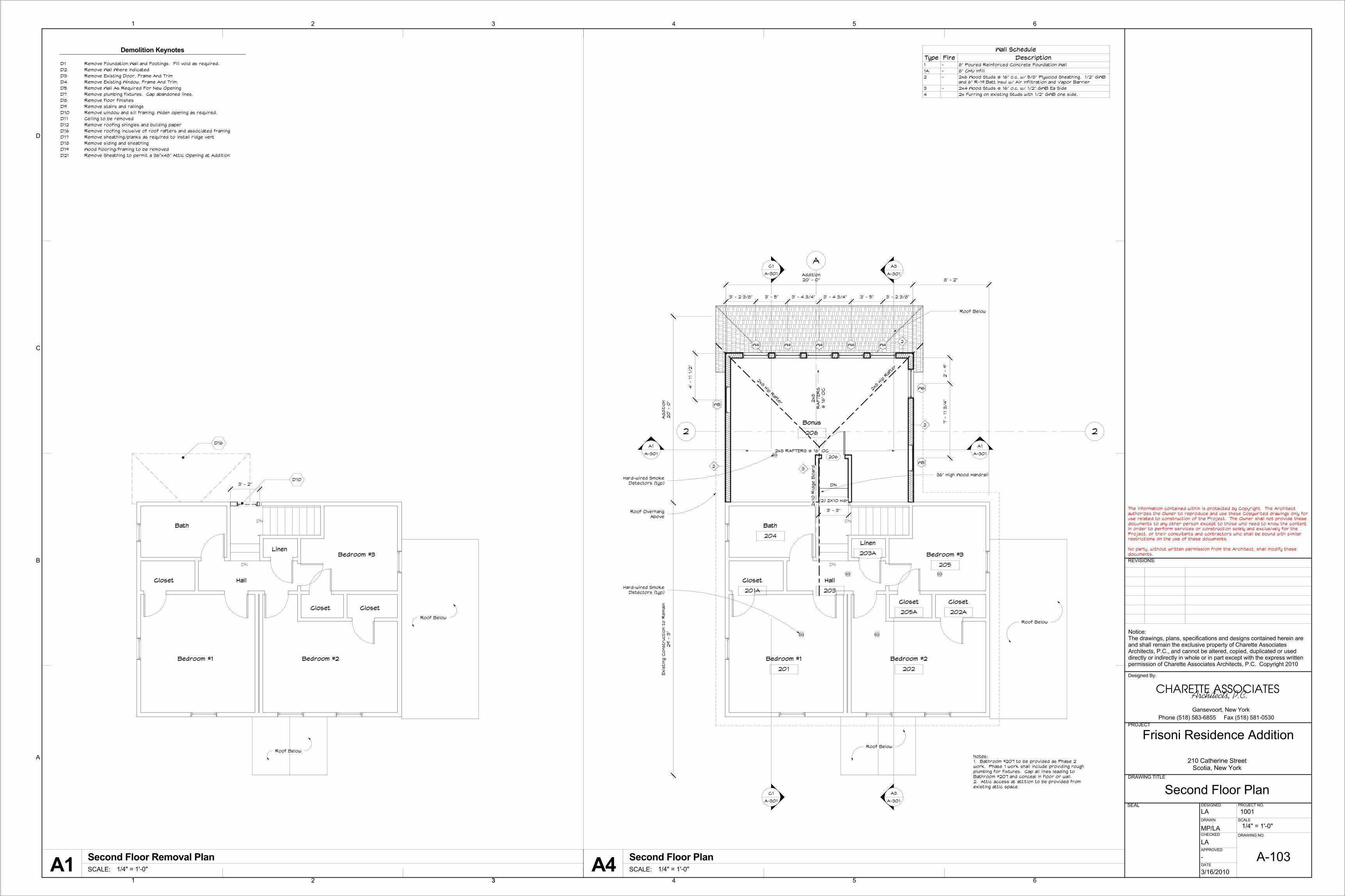
A-105C3
9' - 1" 1' - 1"
6' -
7 1
/4"
3 1
/2"
3' -
2 1
/2"
3 1
/2"
4' -
2 1
/2"
2' - 3" 3' - 2" 5' - 9 1/2" 1' - 4 1/2"
6' -
5"
3' -
0"
1' -
6"
16' -
7 1
/2"
27' -
6 1
/2"
40"Range
W2430
W2430
W2430
BD24
SB36
BC48
B15
W2624
W2624
W2624
B26
B26
B26
W2430
Lower Counter
Counter: 32" A.F.F.
Counter: 36" A.F.F.
14' -
7 1
/4"
A3
PAN26
B26
W2624x24deep
3' -
9 1
/2" +/
-
First Floor F.F.0"
First Floor Ceiling8' - 0"
W2430W2430 W2430 W2430
BD24 SB36 BC48 B15
Bottom of Beam7' - 0 3/4"
BD24 40"RangeDishWasher
Hood
14' - 7" Clear(2) 2x12
Lowered Counter
FillerPanel
FillerPanel
2' -
8"
3' -
0"
4" Backsplash (typ)
5' -
6"
First Floor F.F.0"
First Floor Ceiling8' - 0"
W2624 W2624 W2624
B26B26 B26 Refrigerator2' -
0"
Bottom of Beam7' - 0 3/4"
B26 PAN26
(2) 2x12 Beam
(2) 2x12 Beam
Wood Shelf
Filler
Filler
4" Backsplash (typ)
4" Base (typ) 3/4" Wood Flooring onExisting Subfloor
1/2" GWB Ceiling1"
W2624x24deep
6
D
C
B
A
3
54321
654321
REVISIONS:
Architects, P.C.
Designed By:
CHARETTE ASSOCIATES
Notice:The drawings, plans, specifications and designs contained herein areand shall remain the exclusive property of Charette AssociatesArchitects, P.C., and cannot be altered, copied, duplicated or useddirectly or indirectly in whole or in part except with the express writtenpermission of Charette Associates Architects, P.C. Copyright 2010
PROJECT
DESIGNED
DRAWN
DRAWING TITLE
SEAL
CHECKED
APPROVED
DATE
PROJECT NO.
SCALE
DRAWING NO.
Gansevoort, New YorkPhone (518) 583-6855 Fax (518) 581-0530
The information contained within is protected by Copyright. The Architectauthorizes the Owner to reproduce and use these Copywrited drawings only foruse related to construction of the Project. The Owner shall not provide thesedocuments to any other person except to those who need to know the contentin order to perform services or construction solely and exclusively for theProject, or their consultants and contractors who shall be bound with similarrestrictions on the use of these documents.
No party, without written permission from the Architect, shall modify thesedocuments.
210 Catherine StreetScotia, New York
1/2" = 1'-0"
Frisoni Residence Addition
Enlarged Kitchen Plan
A-105
1001LA
LA
LA
PF/CF
07/03/10SCALE: 1/2" = 1'-0"
Enlarged Kitchen PlanA1
SCALE: 1/2" = 1'-0"
Elevation 1 - aC3
SCALE: 1/2" = 1'-0"
Elevation 1 - bA3
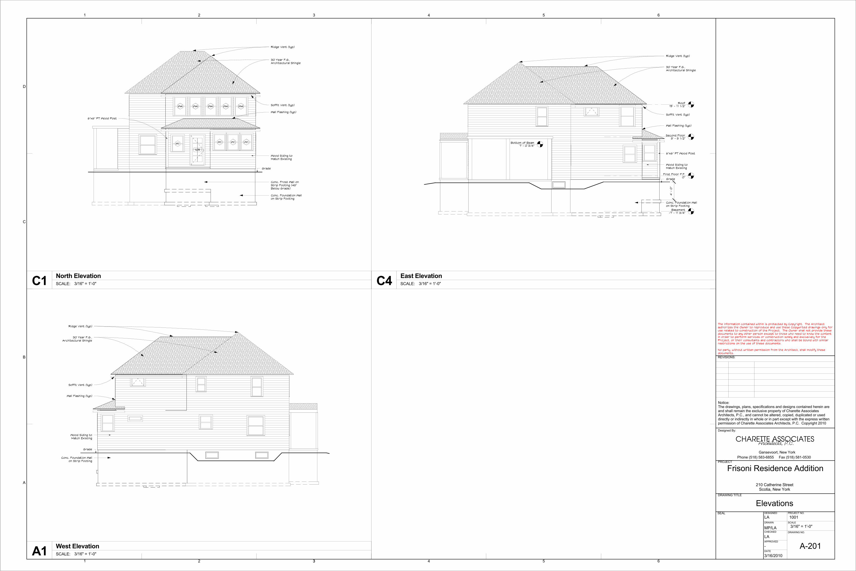
30 Year F.G..Architectural Shingle
Conc. Foundation Wallon Strip Footing
Ridge Vent (typ)
Soffit Vent (typ)
Wall Flashing (typ)
Wood Siding toMatch Existing
6"x6" PT Wood Post
Grade
Conc. Frost Wall onStrip Footing (48"Below Grade)
W4 W4 W4 W4 W4
W1 W1 W1W1
105
30 Year F.G..Architectural Shingle
Conc. Foundation Wallon Strip Footing
Ridge Vent (typ)
Soffit Vent (typ)
Wall Flashing (typ)
Wood Siding toMatch Existing
Grade
First Floor F.F.0"
Second Floor8' - 8 1/2"
Roof15' - 11 1/2"
Basement-7' - 11 3/4"
30 Year F.G..Architectural Shingle
Conc. Foundation Wallon Strip Footing
Ridge Vent (typ)
Soffit Vent (typ)
Wall Flashing (typ)
Wood Siding toMatch Existing
6"x6" PT Wood Post
Grade
4' -
0"
Bottom of Beam7' - 0 3/4"
6
D
C
B
A
3
54321
654321
REVISIONS:
Architects, P.C.
Designed By:
CHARETTE ASSOCIATES
Notice:The drawings, plans, specifications and designs contained herein areand shall remain the exclusive property of Charette AssociatesArchitects, P.C., and cannot be altered, copied, duplicated or useddirectly or indirectly in whole or in part except with the express writtenpermission of Charette Associates Architects, P.C. Copyright 2010
PROJECT
DESIGNED
DRAWN
DRAWING TITLE
SEAL
CHECKED
APPROVED
DATE
PROJECT NO.
SCALE
DRAWING NO.
Gansevoort, New YorkPhone (518) 583-6855 Fax (518) 581-0530
The information contained within is protected by Copyright. The Architectauthorizes the Owner to reproduce and use these Copywrited drawings only foruse related to construction of the Project. The Owner shall not provide thesedocuments to any other person except to those who need to know the contentin order to perform services or construction solely and exclusively for theProject, or their consultants and contractors who shall be bound with similarrestrictions on the use of these documents.
No party, without written permission from the Architect, shall modify thesedocuments.
210 Catherine StreetScotia, New York
3/16" = 1'-0"
Frisoni Residence Addition
Elevations
A-201
1001LA
MP/LA
LA
-
3/16/2010
SCALE: 3/16" = 1'-0"
North ElevationC1
SCALE: 3/16" = 1'-0"
West ElevationA1
SCALE: 3/16" = 1'-0"
East ElevationC4

First Floor F.F.0"
Second Floor8' - 8 1/2"
Roof15' - 11 1/2"
Basement-7' - 11 3/4"
Top of Foundation-10 1/4"2x8 Floor Jst's @ 16" OC
Cont Soffit Vent
2x8 Rim Jst (typ)
Rafters @ 16" oc (typ)
30 YR Architectural Shingles
8" Conc Fdn Wall
Cont. Ridge Vent
Wood Veneered Beam (see plans)
4" Conc. Slab onGrade w/ VB,
Flush Header
8"x 16" Conc. Ftg.
Lowered Counter
Beam - See PlansFor Sizing
4SCH40 Steel Support Pipe,See Plan for Location (typ)
R-38 Batt Insulation
R-19 Batt Insulation
Bonus
206
Kitchen
103
Nook
104
Dining
101
Bath
204
Closet
201A
Bedroom #1
201
4"
R-11 Batt Insulation
First Floor F.F.0"
Second Floor8' - 8 1/2"
Roof15' - 11 1/2"
Basement-7' - 11 3/4"
Top of Foundation-10 1/4"
12"
MIN
.
4" DRAIN TILE TO DAYLIGHT ORSTORM SEWER WITH BACKFLOWPROTECTION IF ALLOWED BYGRADE OR TO SUMP PUMP DRAINTILE
CONCRETEFOOTING OVERUNDISTURBED SOIL
(2) #4 CONTINOUSREBAR USE BENT BARS@ CORNERS
2'-0" #4 REBAR @ 4'-0" O.C.
POUREDFOUNDATION (3500 PSI)
DAMPROOFING
1/2" PLYWOOD SHEATHINGw/TYVEK WRAP
WOOD SIDING TO MATCH EXISTING
SOFFIT OVERHANG WITH CONTINOUS VENT
PROPER VENT AT EAVES- EVERY BAY
30 YEAR FIBERGLASS ROOF SHINGLESOVER COMBINATION SHEATHING/WATERRESISTANT BARRIER (ZIP ROOF SYSTEM)
WOOD RAFTERS PER PLAN
FASCIA
ALUMINUM DRIP EDGE
GRADE
2 MIL. POLY VAPOR BARRIER(IF REQUIRED BY ICYNENE)
3/4" T&G OSB UNDERLAYMENT
2x8 TREATED SILL SEALED
(2) #4 REBAR. CONTINOUSAROUND PERIMETER. AND AT 4'-0" AFF
4" CONC. SLAB OVERVAPOR BARRIER & 4"COMPACTED GRAVEL ORCLEAN SAND FILL ASREQUIRED BY SITECONDITIONS
1/2" x 12" ANCHOR BOLTS@ 4'-0" O.C.
FLOOR JOISTS AS PER PLAN
R11 BATT INSULATION ONFURRING
FLOOR JOISTS AS PER PLAN
2(2x6) PLATE
1/2" GYP BOARD
R19 BATT INSULATION w/ VAPOR BARRIER
2x6 STUDS @ 16"O.C.
CONTINUOUS RIDGE VENT (NOT SHOWN)
R38 BATT INSULATIONW/ VAPOR BARRIER
ALL INTERIOR WALLS TOBE 2x4 STUDS @
16"O.C.
2x6 SILL PLATE
1/2" EXPANSION JOINT (TYP)
#5 VERT REBAR @ 48" O.C.
NOTE:REINFORCING IS BASED ON 8" WIDE 8'-0" HIGHFOUNDATION WALL W/ BACKFILL HEIGHT NOT TO EXCEED7'-0" FROM T/ SLAB. SOIL TYPE IS GW, GP, SW OR SP.CONSULT ARCHITECT IF DIFFERENT CONDITIONS AREFOUND.
MATCH EXISTING ROOF EAVE SLOPE
First Floor F.F.0"
Basement-7' - 11 3/4"
7' -
0"
7 23/3
2"
9"
3' -
0"
4" max.
Wood Handrail
6' -
8" Cle
ar M
in.
(2) 2x8 Header
6
D
C
B
A
3
54321
654321
REVISIONS:
Architects, P.C.
Designed By:
CHARETTE ASSOCIATES
Notice:The drawings, plans, specifications and designs contained herein areand shall remain the exclusive property of Charette AssociatesArchitects, P.C., and cannot be altered, copied, duplicated or useddirectly or indirectly in whole or in part except with the express writtenpermission of Charette Associates Architects, P.C. Copyright 2010
PROJECT
DESIGNED
DRAWN
DRAWING TITLE
SEAL
CHECKED
APPROVED
DATE
PROJECT NO.
SCALE
DRAWING NO.
Gansevoort, New YorkPhone (518) 583-6855 Fax (518) 581-0530
The information contained within is protected by Copyright. The Architectauthorizes the Owner to reproduce and use these Copywrited drawings only foruse related to construction of the Project. The Owner shall not provide thesedocuments to any other person except to those who need to know the contentin order to perform services or construction solely and exclusively for theProject, or their consultants and contractors who shall be bound with similarrestrictions on the use of these documents.
No party, without written permission from the Architect, shall modify thesedocuments.
210 Catherine StreetScotia, New York
As indicated
Frisoni Residence Addition
Building Sections
A-301
1001LA
MP/LA
LA
-
3/16/2010
SCALE: 1/4" = 1'-0"
Building SectionC1
SCALE: 1/4" = 1'-0"
Building SectionA1 SCALE: 3/4" = 1'-0"
Typical Wall SectionA5SCALE: 1/4" = 1'-0"
Section @ StairsA3
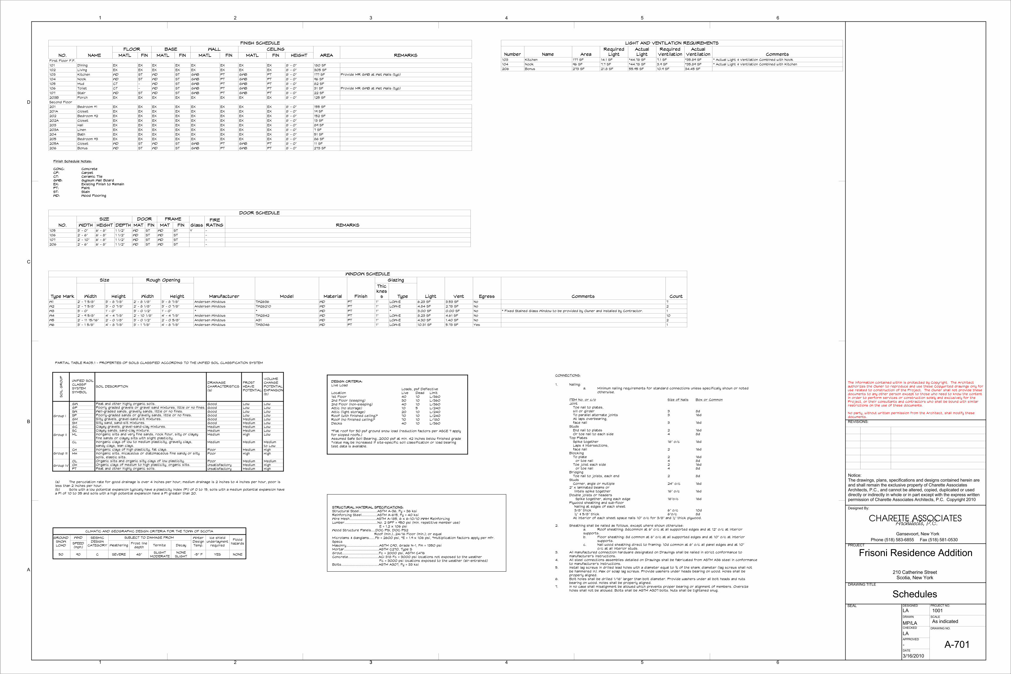
Finish Schedule Notes:
CONC: ConcreteCP: CarpetCT: Ceramic TileGWB: Gypsum Wall BoardEX: Existing Finish to RemainPT: PaintST: StainWD: Wood Flooring
SO
IL G
RO
UP UNIFIED SOILCLASSIFSYSTEMSYMBOL
SOIL DESCRIPTIONDRAINAGECHARACTERISTICS(a)
FROSTHEAVEPOTENTIAL
VOLUMECHANGEPOTENTIALEXPANSION(b)
Group I
GWGPSWSPGMSMGCSCML
CL
CHMH
OLOHPT
Peat and other highly organic soils.Poorly graded gravels or gravel sand mixtures, little or no fines.Well-graded sands, gravelly sands, little or no fines.Poorly-graded sands or gravelly sands, little or no fines.Silty gravels, gravel-sand-silt mixtures.Silty sand, sand-silt mixtures.Clayey gravels, gravel-sand-clay mixtures.Clayey sands, sand-clay mixture.Inorganic silts and very fine sands, rock flour, silty or clayeyfine sands or clayey silts with slight plasticity.Inorganic clays of low to medium plasticity, gravelly clays,sandy clays, lean clays.Inorganic clays of high plasticity, fat clays.Inorganic silts, micaceous or diatomaceous fine sandy or siltysoils, elastic silts.Organic silts and organic silty clays of low plasticity.Organic clays of medium to high plasticity, organic silts.Peat and other highly organic soils.
GoodGoodGoodGoodGoodGoodMediumMediumMedium
Medium
PoorPoor
PoorUnsatisfactoryUnsatisfactory
LowLowLowLowMediumMediumMediumMediumHigh
Medium
MediumHigh
MediumMediumMedium
LowLowLowLowLowLowLowLowLow
Mediumto LowHighHigh
MediumHighHigh
Group II
Group III
Group IV
(a) The percolation rate for good drainage is over 4 inches per hour; medium drainage is 2 inches to 4 inches per hour, poor isless than 2 inches per hour.(b) Soils with a low potential expansion typically have a plasticity index (Pl) of 0 to 15, soils with a medium potential expansion havea Pl of 10 to 35 and soils with a high potential expansion have a Pl greater than 20.
PARTIAL TABLE R405.1 - PROPERTIES OF SOILS CLASSIFIED ACCORDING TO THE UNIFIED SOIL CLASSIFICATION SYSTEM
Ice shieldunderlayment
required
GROUNDSNOWLOAD
48"
SUBJECT TO DAMAGE FROM
Frost linedepth
CLIMATIC AND GEOGRAPHIC DESIGN CRITERIA FOR THE TOWN OF SCOTIA
SEISMICDESIGN
CATEGORY
WIND
90
SPEED(mph)
50 C
Weathering
SEVERE
Decay
NONESLIGHT
Termite
SLIGHTMODERATE
WinterDesignTemp.
-5° F YES
Floodhazards
NONE
DESIGN CRITERIA:Live Load
Loads, psf DeflectiveLocation Live Dead Limit1st Floor 40 10 L/3602nd Floor (sleeping) 30 10 L/3602nd Floor (non-sleeping) 40 10 L/360Attic (no storage) 10 5 L/240Attic (light storage) 20 10 L/240Roof (with finished ceiling)* 70 10 L/240Roof (no finished ceiling)* 70 10 L/180Decks 40 10 L/360
*Flat roof for 50 psf ground snow load (reduction factors per ASCE 7 applyfor sloped roofs.)Assumed Safe Soil Bearing...2000 psf at min. 42 inches below finished grade*Value may be increased if site-specific soil classification or load bearingtest data is available.
CONNECTIONS:
1.
2.
3.
4.
5.
6.
7.
Nailing:a. Minimum nailing requirements for standard connections unless specifically shown or noted
otherwise.
ITEM No. or c/o Size of Nails Box or CommonJoint Toe nail to plates, sill or girder 3 8d To parallel alternate joints 3 16d At laps overbearing, face nail 3 16dStuds End nail to plates 2 16d Or toe nail to each side 4 8dTop Plates Spike together 16" o/c 16d Laps & intersections, face nail 2 16dBlocking To plate 2 16d or toe nail 4 8d Toe joist each side 2 16d or toe nail 4 8dBridging Toe nail to joists, each end 2 8dStuds Corner, angle or multiple 24" o/c 16d2" x laminated beams or lintels spike together 16" o/c 16dDouble joists or headers Spike together, along each edge 16"o/c 16dPlywood sheathing and sub-floor Nailing at edges of each sheet 3/8" thick 6" o/c 10d ½" & 5/8" thick 6"o/c 8d At interior of each sheet space nails 10" o/c for 3/8" and ½" thick plywood.
Sheathing shall be nailed as follows, except where shown otherwise:a. Roof sheathing: 8dcommon at 6" o/c at all supported edges and at 12" o/c at interior supports.b. Floor sheathing: 8d common at 6" o/c at all supported edges and at 10" o/c at interior
supports.c. Nail wood sheathing direct to framing: 10d common at 6" o/c all panel edges and at 10"
o/c at all interior studs.All manufactured connection hardware designated on Drawings shall be nailed in strict conformance tomanufacturer's instructions.All steel connections assemblies detailed on Drawings shall be fabricated from ASTM A36 steel in conformanceto manufacturer's instructions.Install lag screws in drilled lead holes with a diameter equal to ¾ of the shank diameter (lag screws shall notbe hammered in). Wax or soap lag screws. Provide washers under heads bearing on wood. Holes shall beproperly aligned.Bolt holes shall be drilled 1/16" larger than bolt diameter. Provide washers under all bolt heads and nutsbearing on wood. Holes shall be properly aligned.In no case shall misalignment be allowed which prevents proper bearing or alignment of members. Oversizeholes shall not be allowed. Bolts shall be ASTM A307 bolts. Nuts shall be tightened snug.
STRUCTURAL MATERIAL SPECIFICATIONS:Structural Steel.....................ASTM A-36, Fy = 36 ksiReinforcing Steel..................ASTM A-615, Fy = 40 ksiWire Mesh...............................ASTM A-185, 6 x 6-10/10 WWM ReinforcingLumber......................................No. 2 SPF = 950 psi (min. repetitive member use)
E = 1.2 x 10⁶ psiWood Structure Panels.....DOC PSI, DOC PS2
Roof (min.)...24/16 Floor (min.); or equalMicrolams & Ganglams.......Fb = 2600 psi, *E = 1.9 x 10⁶ psi, *Multiplication factors apply per mfr.SpecsMasonry......................................ASTM C90, Grade N-1, Fm = 1350 psiMortar........................................ASTM C270, Type SGrout..........................................Fc = 2000 psi, ASTM C476Concrete...................................ACI 318 Fc = 3000 psi locations not exposed to the weather
Fc = 3000 psi locations exposed to the weather (air-entrained)Bolts...........................................ASTM A307, Fy = 33 ksi
6
D
C
B
A
3
54321
654321
REVISIONS:
Architects, P.C.
Designed By:
CHARETTE ASSOCIATES
Notice:The drawings, plans, specifications and designs contained herein areand shall remain the exclusive property of Charette AssociatesArchitects, P.C., and cannot be altered, copied, duplicated or useddirectly or indirectly in whole or in part except with the express writtenpermission of Charette Associates Architects, P.C. Copyright 2010
PROJECT
DESIGNED
DRAWN
DRAWING TITLE
SEAL
CHECKED
APPROVED
DATE
PROJECT NO.
SCALE
DRAWING NO.
Gansevoort, New YorkPhone (518) 583-6855 Fax (518) 581-0530
The information contained within is protected by Copyright. The Architectauthorizes the Owner to reproduce and use these Copywrited drawings only foruse related to construction of the Project. The Owner shall not provide thesedocuments to any other person except to those who need to know the contentin order to perform services or construction solely and exclusively for theProject, or their consultants and contractors who shall be bound with similarrestrictions on the use of these documents.
No party, without written permission from the Architect, shall modify thesedocuments.
210 Catherine StreetScotia, New York
As indicated
Frisoni Residence Addition
Schedules
A-701
1001LA
MP/LA
LA
-
3/16/2010
DOOR SCHEDULE
NO.SIZE DOOR FRAME
GlassFIRE
RATING REMARKSWIDTH HEIGHT DEPTH MAT FIN MAT FIN105 3' - 0" 6' - 8" 1 1/2" WD ST WD ST Y -106 2' - 6" 6' - 8" 1 1/2" WD ST WD ST -107 2' - 10" 6' - 8" 1 1/2" WD ST WD ST -206 2' - 6" 6' - 8" 1 1/2" WD ST WD ST -
FINISH SCHEDULE
NO. NAMEFLOOR BASE WALL CEILING
AREA REMARKSMATL FIN MATL FIN MATL FIN MATL FIN HEIGHTFirst Floor F.F.101 Dining EX EX EX EX EX EX EX EX 8' - 0" 180 SF102 Living EX EX EX EX EX EX EX EX 8' - 0" 305 SF103 Kitchen WD ST WD ST GWB PT GWB PT 8' - 0" 177 SF Provide MR GWB at Wet Walls (typ)104 Nook WD ST WD ST GWB PT GWB PT 8' - 0" 96 SF105 Mud CT - WD ST GWB PT GWB PT 8' - 0" 82 SF106 Toilet CT - WD ST GWB PT GWB PT 8' - 0" 31 SF Provide MR GWB at Wet Walls (typ)107 Stair WD ST WD ST GWB PT GWB PT 8' - 0" 22 SF203B Porch EX EX EX EX EX EX EX EX 8' - 0" 125 SFSecond Floor201 Bedroom #1 EX EX EX EX EX EX EX EX 8' - 0" 155 SF201A Closet EX EX EX EX EX EX EX EX 8' - 0" 19 SF202 Bedroom #2 EX EX EX EX EX EX EX EX 8' - 0" 152 SF202A Closet EX EX EX EX EX EX EX EX 8' - 0" 13 SF203 Hall EX EX EX EX EX EX EX EX 8' - 0" 89 SF203A Linen EX EX EX EX EX EX EX EX 8' - 0" 7 SF204 Bath EX EX EX EX EX EX EX EX 8' - 0" 51 SF205 Bedroom #3 EX EX EX EX EX EX EX EX 8' - 0" 86 SF205A Closet WD ST WD ST GWB PT GWB PT 8' - 0" 11 SF206 Bonus WD ST WD ST GWB PT GWB PT 8' - 0" 273 SF
WINDOW SCHEDULE
Type Mark
Size Rough Opening
Manufacturer Model Material Finish
Glazing
Light Vent Egress Comments CountWidth Height Width Height
Thicknes
s TypeW1 2' - 7 5/8" 3' - 8 7/8" 2' - 8 1/8" 3' - 8 7/8" Andersen Windows TW2636 WD PT 1" LOW-E 6.23 SF 3.53 SF No 7W2 2' - 7 5/8" 3' - 0 7/8" 2' - 8 1/8" 3' - 0 7/8" Andersen Windows TW26210 WD PT 1" LOW-E 4.84 SF 2.78 SF No 2W3 3' - 0" 1' - 0" 3' - 0 1/2" 1' - 0" * * WD PT 1" * 3.00 SF 0.00 SF No * Fixed Stained Glass Window to be provided by Owner and Installed by Contractor. 1W4 2' - 9 5/8" 4' - 4 7/8" 2' - 10 1/8" 4' - 4 7/8" Andersen Windows TW2842 WD PT 1" LOW-E 8.23 SF 4.61 SF No 10W5 2' - 11 15/16" 2' - 0 1/8" 3' - 0 1/2" 2' - 0 5/8" Andersen Windows A31 WD PT 1" LOW-E 4.30 SF 1.40 SF No 2W6 3' - 1 5/8" 4' - 8 7/8" 3' - 1 7/8" 4' - 8 7/8" Andersen Windows TW3046 WD PT 1" LOW-E 10.31 SF 5.73 SF Yes 1
LIGHT AND VENTILATION REQUIREMENTS
Number Name AreaRequired
LightActualLight
RequiredVentilation
ActualVentilation Comments
103 Kitchen 177 SF 14.1 SF *44.78 SF 7.1 SF *35.89 SF * Actual Light & Ventilation Combined with Nook104 Nook 96 SF 7.7 SF *44.78 SF 3.9 SF *35.89 SF * Actual Light & Ventilation Combined with Kitchen206 Bonus 273 SF 21.8 SF 55.95 SF 10.9 SF 34.45 SF

6
D
C
B
A
3
54321
654321
REVISIONS:
Architects, P.C.
Designed By:
CHARETTE ASSOCIATES
Notice:The drawings, plans, specifications and designs contained herein areand shall remain the exclusive property of Charette AssociatesArchitects, P.C., and cannot be altered, copied, duplicated or useddirectly or indirectly in whole or in part except with the express writtenpermission of Charette Associates Architects, P.C. Copyright 2010
PROJECT
DESIGNED
DRAWN
DRAWING TITLE
SEAL
CHECKED
APPROVED
DATE
PROJECT NO.
SCALE
DRAWING NO.
Gansevoort, New YorkPhone (518) 583-6855 Fax (518) 581-0530
The information contained within is protected by Copyright. The Architectauthorizes the Owner to reproduce and use these Copywrited drawings only foruse related to construction of the Project. The Owner shall not provide thesedocuments to any other person except to those who need to know the contentin order to perform services or construction solely and exclusively for theProject, or their consultants and contractors who shall be bound with similarrestrictions on the use of these documents.
No party, without written permission from the Architect, shall modify thesedocuments.
210 Catherine StreetScotia, New York
6" = 1'-0"
Frisoni Residence Addition
Material Specifications
A-801
1001LA
MP/LA
LA
-
7/21/2010
Recommended