(Version 2 Jan 2014)
© D Bird 2014
KK 2.1 Multi-Rotor Control Board
User Guide The next evolution of the rotor revolution is here!! The KK2.1 is packing new found power with updated
sensors, memory and header pins.
Designed exclusively for HobbyKing by the grandfather of the KK revolution, Rolf R Bakke, the KK2.1 is
the next evolution of the first generation KK flight control boards and has been engineered from the
ground-up to bring multi-rotor flight to everyone, not just the experts. The LCD screen and built-in
software makes installation and set-up easier than ever.
The original KK gyro system has been updated to the incredibly sensitive 6050 MPU system making this
the most stable KK board ever and adds the addition of an auto-level function. At the heart of the
KK2.1 is the ATMEL Mega 644PA 8-bit AVR RISC-based microcontroller with 64k of memory.
An additional header has been added for voltage detection, so now there is no need for on-board
soldering. A handy piezo buzzer is also included with the board for audio warning when activating and
deactivating the board, which can be supplemented with an LED for visual signaling.
A host of multi-rotor craft types are pre-installed, simply select your craft type, check motor
layout/propeller direction, calibrate your ESCs and radio and you’re ready to go! All of which is done
with easy to follow on screen prompts!
If you’re new to multi-rotor flight or have been unsure about how to setup a KK board then the KK2.1
was built for you. The 6 Pin USBasp AVR programming interface ensures future software updates will be
quick and easy.
Go ahead and get started.
© D Bird 2014 Page 2
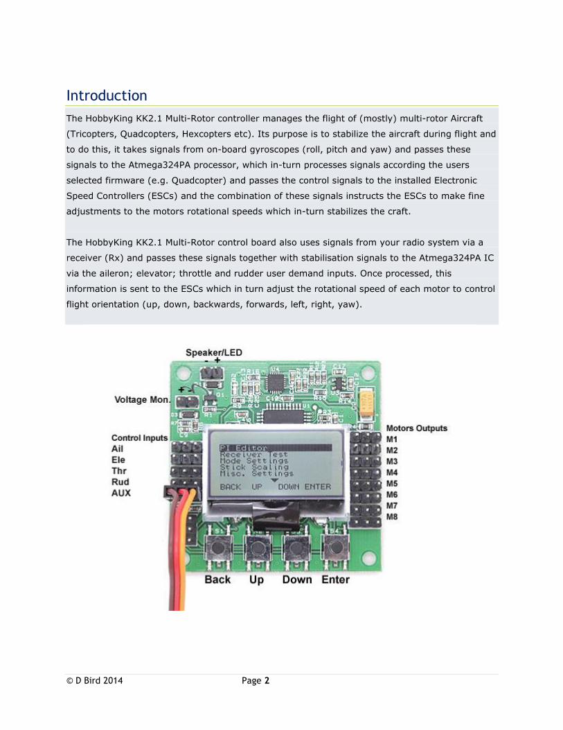
Introduction
The HobbyKing KK2.1 Multi-Rotor controller manages the flight of (mostly) multi-rotor Aircraft
(Tricopters, Quadcopters, Hexcopters etc). Its purpose is to stabilize the aircraft during flight and
to do this, it takes signals from on-board gyroscopes (roll, pitch and yaw) and passes these
signals to the Atmega324PA processor, which in-turn processes signals according the users
selected firmware (e.g. Quadcopter) and passes the control signals to the installed Electronic
Speed Controllers (ESCs) and the combination of these signals instructs the ESCs to make fine
adjustments to the motors rotational speeds which in-turn stabilizes the craft.
The HobbyKing KK2.1 Multi-Rotor control board also uses signals from your radio system via a
receiver (Rx) and passes these signals together with stabilisation signals to the Atmega324PA IC
via the aileron; elevator; throttle and rudder user demand inputs. Once processed, this
information is sent to the ESCs which in turn adjust the rotational speed of each motor to control
flight orientation (up, down, backwards, forwards, left, right, yaw).
© D Bird 2014 Page 3
Initial Set-Up
STEP-1 Mount the FC on the frame with the LCD facing front
and the buttons facing back. You can use the supplied anti-
static foam container as a form of protective case for the Flight
Controller on the craft.
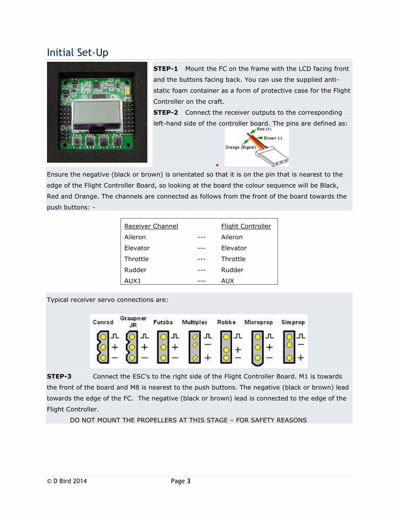
STEP-2 Connect the receiver outputs to the corresponding
left-hand side of the controller board. The pins are defined as:
Ensure the negative (black or brown) is orientated so that it is on the pin that is nearest to the
edge of the Flight Controller Board, so looking at the board the colour sequence will be Black,
Red and Orange. The channels are connected as follows from the front of the board towards the
push buttons: -
Receiver Channel Flight Controller
Aileron --- Aileron
Elevator --- Elevator
Throttle --- Throttle
Rudder --- Rudder
AUX1 --- AUX
Typical receiver servo connections are:
STEP-3 Connect the ESC’s to the right side of the Flight Controller Board. M1 is towards
the front of the board and M8 is nearest to the push buttons. The negative (black or brown) lead
towards the edge of the FC. The negative (black or brown) lead is connected to the edge of the
Flight Controller.
DO NOT MOUNT THE PROPELLERS AT THIS STAGE – FOR SAFETY REASONS
© D Bird 2014 Page 4
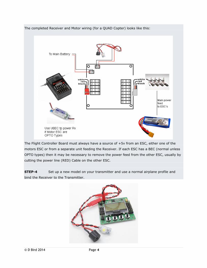
The completed Receiver and Motor wiring (for a QUAD Copter) looks like this:
The Flight Controller Board must always have a source of +5v from an ESC, either one of the
motors ESC or from a separate unit feeding the Receiver. If each ESC has a BEC (normal unless
OPTO types) then it may be necessary to remove the power feed from the other ESC, usually by
cutting the power line (RED) Cable on the other ESC.
STEP-4 Set up a new model on your transmitter and use a normal airplane profile and
bind the Receiver to the Transmitter.
© D Bird 2014 Page 5
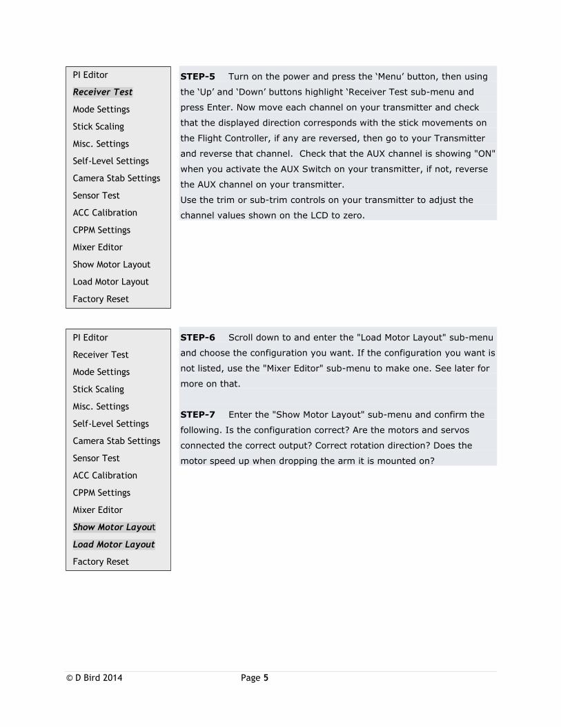
STEP-5 Turn on the power and press the ‘Menu’ button, then using
the ‘Up’ and ‘Down’ buttons highlight ‘Receiver Test sub-menu and
press Enter. Now move each channel on your transmitter and check
that the displayed direction corresponds with the stick movements on
the Flight Controller, if any are reversed, then go to your Transmitter
and reverse that channel. Check that the AUX channel is showing "ON"
when you activate the AUX Switch on your transmitter, if not, reverse
the AUX channel on your transmitter.
Use the trim or sub-trim controls on your transmitter to adjust the
channel values shown on the LCD to zero.
STEP-6 Scroll down to and enter the "Load Motor Layout" sub-menu
and choose the configuration you want. If the configuration you want is
not listed, use the "Mixer Editor" sub-menu to make one. See later for
more on that.
STEP-7 Enter the "Show Motor Layout" sub-menu and confirm the
following. Is the configuration correct? Are the motors and servos
connected the correct output? Correct rotation direction? Does the
motor speed up when dropping the arm it is mounted on?
PI Editor
Receiver Test
Mode Settings
Stick Scaling
Misc. Settings
Self-Level Settings
Camera Stab Settings
Sensor Test
ACC Calibration
CPPM Settings
Mixer Editor
Show Motor Layout
Load Motor Layout
Factory Reset
PI Editor
Receiver Test
Mode Settings
Stick Scaling
Misc. Settings
Self-Level Settings
Camera Stab Settings
Sensor Test
ACC Calibration
CPPM Settings
Mixer Editor
Show Motor Layout
Load Motor Layout
Factory Reset
© D Bird 2014 Page 6
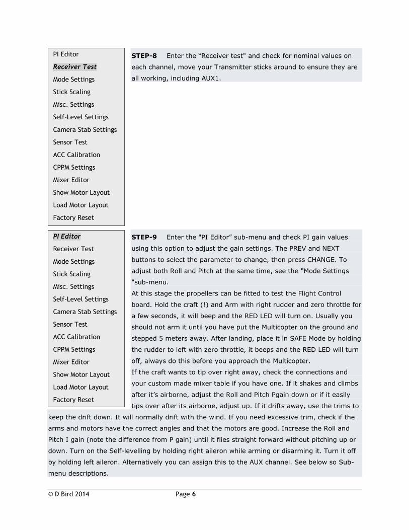
STEP-8 Enter the “Receiver test" and check for nominal values on
each channel, move your Transmitter sticks around to ensure they are
all working, including AUX1.
STEP-9 Enter the "PI Editor” sub-menu and check PI gain values
using this option to adjust the gain settings. The PREV and NEXT
buttons to select the parameter to change, then press CHANGE. To
adjust both Roll and Pitch at the same time, see the "Mode Settings
"sub-menu.
At this stage the propellers can be fitted to test the Flight Control
board. Hold the craft (!) and Arm with right rudder and zero throttle for
a few seconds, it will beep and the RED LED will turn on. Usually you
should not arm it until you have put the Multicopter on the ground and
stepped 5 meters away. After landing, place it in SAFE Mode by holding
the rudder to left with zero throttle, it beeps and the RED LED will turn
off, always do this before you approach the Multicopter.
If the craft wants to tip over right away, check the connections and
your custom made mixer table if you have one. If it shakes and climbs
after it’s airborne, adjust the Roll and Pitch Pgain down or if it easily
tips over after its airborne, adjust up. If it drifts away, use the trims to
keep the drift down. It will normally drift with the wind. If you need excessive trim, check if the
arms and motors have the correct angles and that the motors are good. Increase the Roll and
Pitch I gain (note the difference from P gain) until it flies straight forward without pitching up or
down. Turn on the Self-levelling by holding right aileron while arming or disarming it. Turn it off
by holding left aileron. Alternatively you can assign this to the AUX channel. See below so Sub-
menu descriptions.
PI Editor
Receiver Test
Mode Settings
Stick Scaling
Misc. Settings
Self-Level Settings
Camera Stab Settings
Sensor Test
ACC Calibration
CPPM Settings
Mixer Editor
Show Motor Layout
Load Motor Layout
Factory Reset
PI Editor
Receiver Test
Mode Settings
Stick Scaling
Misc. Settings
Self-Level Settings
Camera Stab Settings
Sensor Test
ACC Calibration
CPPM Settings
Mixer Editor
Show Motor Layout
Load Motor Layout
Factory Reset
© D Bird 2014 Page 7
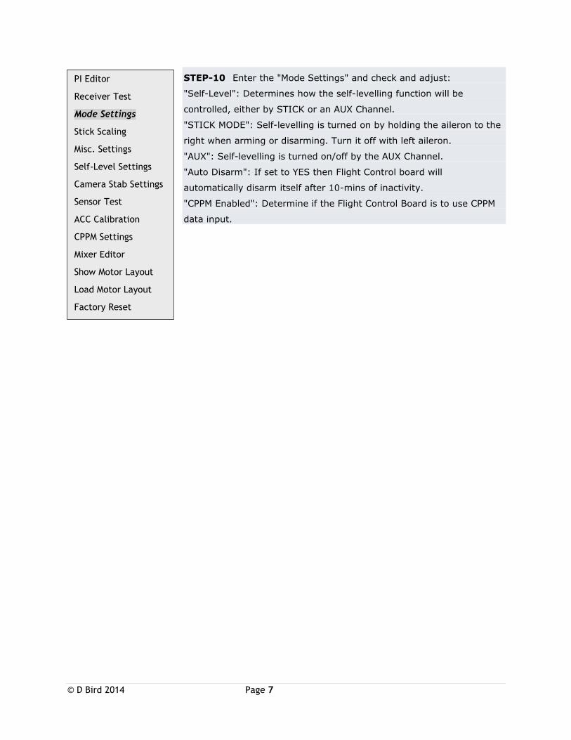
STEP-10 Enter the "Mode Settings" and check and adjust:
"Self-Level": Determines how the self-levelling function will be
controlled, either by STICK or an AUX Channel.
"STICK MODE": Self-levelling is turned on by holding the aileron to the
right when arming or disarming. Turn it off with left aileron.
"AUX": Self-levelling is turned on/off by the AUX Channel.
"Auto Disarm": If set to YES then Flight Control board will
automatically disarm itself after 10-mins of inactivity.
"CPPM Enabled": Determine if the Flight Control Board is to use CPPM
data input.
PI Editor
Receiver Test
Mode Settings
Stick Scaling
Misc. Settings
Self-Level Settings
Camera Stab Settings
Sensor Test
ACC Calibration
CPPM Settings
Mixer Editor
Show Motor Layout
Load Motor Layout
Factory Reset
© D Bird 2014 Page 8
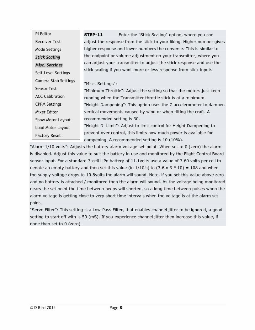
STEP-11 Enter the "Stick Scaling" option, where you can
adjust the response from the stick to your liking. Higher number gives
higher response and lower numbers the converse. This is similar to
the endpoint or volume adjustment on your transmitter, where you
can adjust your transmitter to adjust the stick response and use the
stick scaling if you want more or less response from stick inputs.
"Misc. Settings":
"Minimum Throttle": Adjust the setting so that the motors just keep
running when the Transmitter throttle stick is at a minimum.
"Height Dampening": This option uses the Z accelerometer to dampen
vertical movements caused by wind or when tilting the craft. A
recommended setting is 30.
"Height D. Limit": Adjust to limit control for Height Dampening to
prevent over control, this limits how much power is available for
dampening. A recommended setting is 10 (10%).
"Alarm 1/10 volts”: Adjusts the battery alarm voltage set-point. When set to 0 (zero) the alarm
is disabled. Adjust this value to suit the battery in use and monitored by the Flight Control Board
sensor input. For a standard 3-cell LiPo battery of 11.1volts use a value of 3.60 volts per cell to
denote an empty battery and then set this value (in 1/10’s) to (3.6 x 3 * 10) = 108 and when
the supply voltage drops to 10.8volts the alarm will sound. Note, if you set this value above zero
and no battery is attached / monitored then the alarm will sound. As the voltage being monitored
nears the set point the time between beeps will shorten, so a long time between pulses when the
alarm voltage is getting close to very short time intervals when the voltage is at the alarm set
point.
“Servo Filter”: This setting is a Low-Pass Filter, that enables channel jitter to be ignored, a good
setting to start off with is 50 (mS). If you experience channel jitter then increase this value, if
none then set to 0 (zero).
PI Editor
Receiver Test
Mode Settings
Stick Scaling
Misc. Settings
Self-Level Settings
Camera Stab Settings
Sensor Test
ACC Calibration
CPPM Settings
Mixer Editor
Show Motor Layout
Load Motor Layout
Factory Reset
© D Bird 2014 Page 9
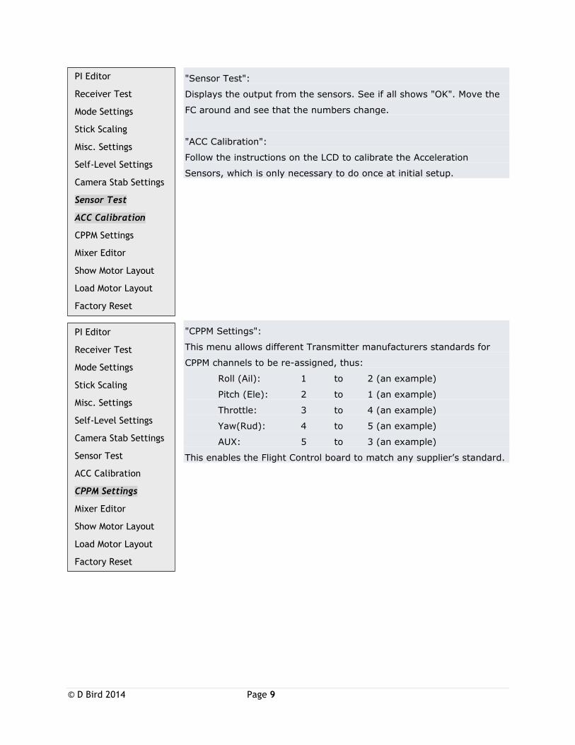
"Sensor Test":
Displays the output from the sensors. See if all shows "OK". Move the
FC around and see that the numbers change.
"ACC Calibration":
Follow the instructions on the LCD to calibrate the Acceleration
Sensors, which is only necessary to do once at initial setup.
"CPPM Settings":
This menu allows different Transmitter manufacturers standards for
CPPM channels to be re-assigned, thus:
Roll (Ail): 1 to 2 (an example)
Pitch (Ele): 2 to 1 (an example)
Throttle: 3 to 4 (an example)
Yaw(Rud): 4 to 5 (an example)
AUX: 5 to 3 (an example)
This enables the Flight Control board to match any supplier’s standard.
PI Editor
Receiver Test
Mode Settings
Stick Scaling
Misc. Settings
Self-Level Settings
Camera Stab Settings
Sensor Test
ACC Calibration
CPPM Settings
Mixer Editor
Show Motor Layout
Load Motor Layout
Factory Reset
PI Editor
Receiver Test
Mode Settings
Stick Scaling
Misc. Settings
Self-Level Settings
Camera Stab Settings
Sensor Test
ACC Calibration
CPPM Settings
Mixer Editor
Show Motor Layout
Load Motor Layout
Factory Reset
© D Bird 2014 Page 10
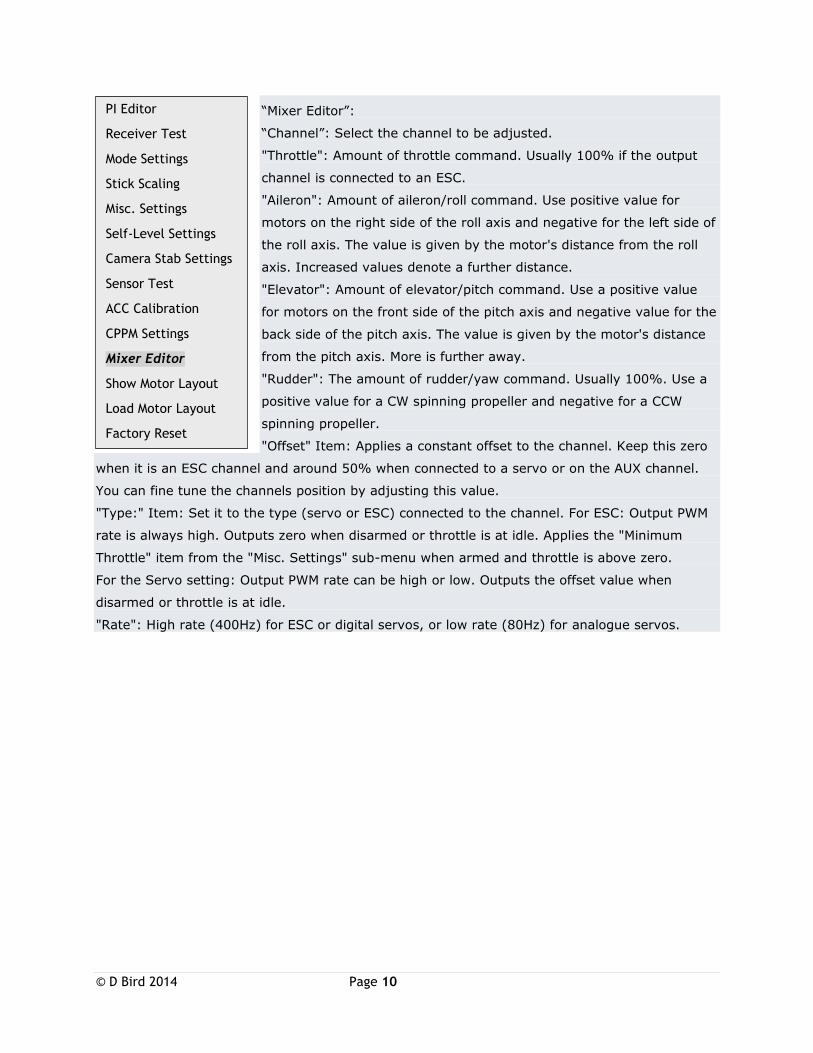
“Mixer Editor”:
“Channel”: Select the channel to be adjusted.
"Throttle": Amount of throttle command. Usually 100% if the output
channel is connected to an ESC.
"Aileron": Amount of aileron/roll command. Use positive value for
motors on the right side of the roll axis and negative for the left side of
the roll axis. The value is given by the motor's distance from the roll
axis. Increased values denote a further distance.
"Elevator": Amount of elevator/pitch command. Use a positive value
for motors on the front side of the pitch axis and negative value for the
back side of the pitch axis. The value is given by the motor's distance
from the pitch axis. More is further away.
"Rudder": The amount of rudder/yaw command. Usually 100%. Use a
positive value for a CW spinning propeller and negative for a CCW
spinning propeller.
"Offset" Item: Applies a constant offset to the channel. Keep this zero
when it is an ESC channel and around 50% when connected to a servo or on the AUX channel.
You can fine tune the channels position by adjusting this value.
"Type:" Item: Set it to the type (servo or ESC) connected to the channel. For ESC: Output PWM
rate is always high. Outputs zero when disarmed or throttle is at idle. Applies the "Minimum
Throttle" item from the "Misc. Settings" sub-menu when armed and throttle is above zero.
For the Servo setting: Output PWM rate can be high or low. Outputs the offset value when
disarmed or throttle is at idle.
"Rate": High rate (400Hz) for ESC or digital servos, or low rate (80Hz) for analogue servos.
PI Editor
Receiver Test
Mode Settings
Stick Scaling
Misc. Settings
Self-Level Settings
Camera Stab Settings
Sensor Test
ACC Calibration
CPPM Settings
Mixer Editor
Show Motor Layout
Load Motor Layout
Factory Reset
© D Bird 2014 Page 11
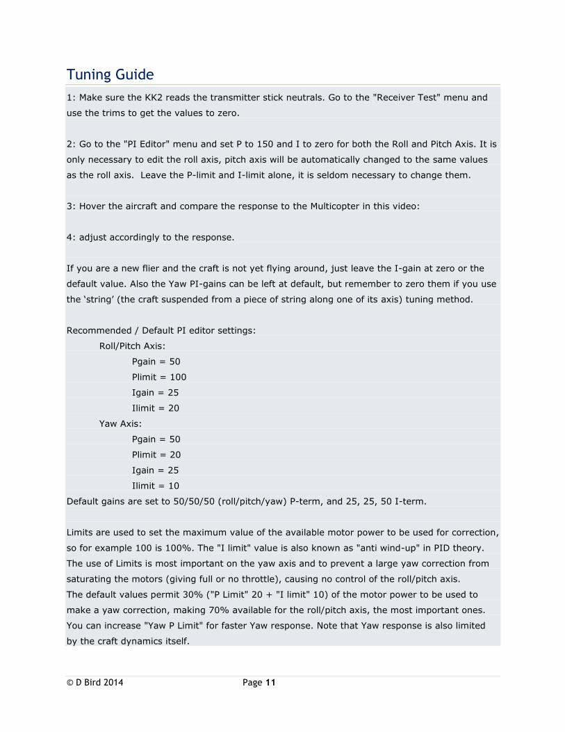
Tuning Guide
1: Make sure the KK2 reads the transmitter stick neutrals. Go to the "Receiver Test" menu and
use the trims to get the values to zero.
2: Go to the "PI Editor" menu and set P to 150 and I to zero for both the Roll and Pitch Axis. It is
only necessary to edit the roll axis, pitch axis will be automatically changed to the same values
as the roll axis. Leave the P-limit and I-limit alone, it is seldom necessary to change them.
3: Hover the aircraft and compare the response to the Multicopter in this video:
4: adjust accordingly to the response.
If you are a new flier and the craft is not yet flying around, just leave the I-gain at zero or the
default value. Also the Yaw PI-gains can be left at default, but remember to zero them if you use
the ‘string’ (the craft suspended from a piece of string along one of its axis) tuning method.
Recommended / Default PI editor settings:
Roll/Pitch Axis:
Pgain = 50
Plimit = 100
Igain = 25
Ilimit = 20
Yaw Axis:
Pgain = 50
Plimit = 20
Igain = 25
Ilimit = 10
Default gains are set to 50/50/50 (roll/pitch/yaw) P-term, and 25, 25, 50 I-term.
Limits are used to set the maximum value of the available motor power to be used for correction,
so for example 100 is 100%. The "I limit" value is also known as "anti wind-up" in PID theory.
The use of Limits is most important on the yaw axis and to prevent a large yaw correction from
saturating the motors (giving full or no throttle), causing no control of the roll/pitch axis.
The default values permit 30% ("P Limit" 20 + "I limit" 10) of the motor power to be used to
make a yaw correction, making 70% available for the roll/pitch axis, the most important ones.
You can increase "Yaw P Limit" for faster Yaw response. Note that Yaw response is also limited
by the craft dynamics itself.
© D Bird 2014 Page 12
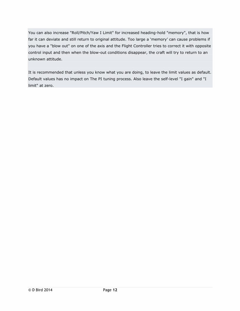
You can also increase "Roll/Pitch/Yaw I Limit" for increased heading-hold "memory", that is how
far it can deviate and still return to original attitude. Too large a ‘memory’ can cause problems if
you have a "blow out" on one of the axis and the Flight Controller tries to correct it with opposite
control input and then when the blow-out conditions disappear, the craft will try to return to an
unknown attitude.
It is recommended that unless you know what you are doing, to leave the limit values as default.
Default values has no impact on The PI tuning process. Also leave the self-level "I gain" and "I
limit" at zero.
© D Bird 2014 Page 13
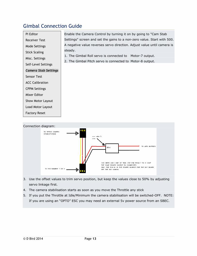
Gimbal Connection Guide
Enable the Camera Control by turning it on by going to "Cam Stab
Settings" screen and set the gains to a non-zero value. Start with 500.
A negative value reverses servo direction. Adjust value until camera is
steady.
1. The Gimbal Roll servo is connected to Motor-7 output.
2. The Gimbal Pitch servo is connected to Motor-8 output.
Connection diagram:
3. Use the offset values to trim servo position, but keep the values close to 50% by adjusting
servo linkage first.
4. The camera stabilisation starts as soon as you move the Throttle any stick
5. If you put the Throttle at Idle/Minimum the camera stabilisation will be switched-OFF. NOTE:
If you are using an “OPTO” ESC you may need an external 5v power source from an SBEC.
PI Editor
Receiver Test
Mode Settings
Stick Scaling
Misc. Settings
Self-Level Settings
Camera Stab Settings
Sensor Test
ACC Calibration
CPPM Settings
Mixer Editor
Show Motor Layout
Load Motor Layout
Factory Reset
© D Bird 2014 Page 14
Accessing the Self-Levelling Mode
1. You can access the self-levelling mode either from the settings of STICK or AUX channel.
2. When set to AUX Mode you must connect a spare channel usually CH5 or Ch6 and changing
the Transmitter switch position will enable/disable Self-Levelling mode.
3. When set to STICK Mode to go into Self-Levelling Mode, you must set the Throttle to
Minimum and set maximum Left Rudder whilst at the same time, setting maximum Left
Aileron to disable SL or maximum Right Aileron to enable SL.
Flight Controller Sounds
1. One Beep (short beep, 2 sec delay) is emitted when the board is armed and the throttle is
closed, this is for safety reasons so you know it’s armed.
2. One Long Beep is emitted when the board is either Armed or Disarmed.
Status Screen
1. Displays the message "SAFE" and the KK2 will not arm unless it says "OK"
General Points
1. Error messages can only be reset by cycling the power, except for the "sensors not
calibrated" message, which is reset after a successful sensor calibration.
2. Error messages include lost RX connection.
3. The KK2.1 has an auto-disarm function and will disarm itself after 20 sec if throttle is at idle.
For extra safety. Can be turned on/off in "Mode Settings" menu.
Lost Model Alarm
1. The KK2.1 has a lost aircraft alarm and starts to beep (1 sec on and 4 sec off) after 30min of
no activity (arm/disarm).

© D Bird 2014 Page 15
Model Types Supported Dualcopter
Tricopter
Y6
Quadcopter +
Quadcopter X
Hexcopter +
Hexcopter X
Octocopter +
Octocopter X
X8 +
X8 X
H8
H6
V8
V6
Aero 1S Aileron
Aero 2S Aileron
Flying Wing
Singlecopter 2M 2S
Singlecopter 1M 4S
Recommended