Keysight Technologies Solutions for Transmit/Receive Module Test
Reach for unrivaled excellence in TR module testing
Air-to-groundtargeting
Track outsidescan volume
Weapon support
SAR wide-areaground mapping
Sea surfacesearch
Ground movingtargets
Search while track
Search while trackSelectable search volumes
Cued search
Electronic protection
– Air-to-air and air-to-ground
with search track mode
– Detect/track multiple targets
– Longer range
– Improved resolution
– Resource manager optimize
performance, reduces workload
– Connectivity with on-board and
off-board sensors
– Advanced sensor integration
and sensor fusion
Multi-Signal
Multi-Beam
Multi-User
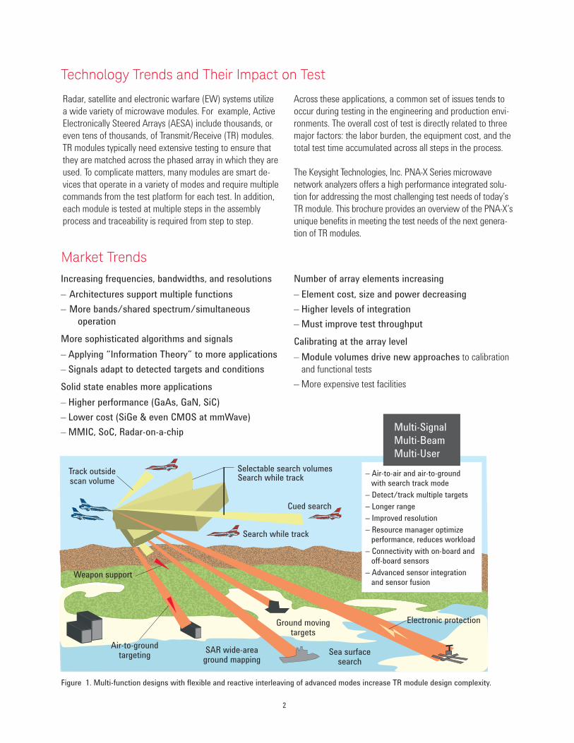
Radar, satellite and electronic warfare (EW) systems utilize
a wide variety of microwave modules. For example, Active
Electronically Steered Arrays (AESA) include thousands, or
even tens of thousands, of Transmit/Receive (TR) modules.
TR modules typically need extensive testing to ensure that
they are matched across the phased array in which they are
used. To complicate matters, many modules are smart de-
vices that operate in a variety of modes and require multiple
commands from the test platform for each test. In addition,
each module is tested at multiple steps in the assembly
process and traceability is required from step to step.
Across these applications, a common set of issues tends to
occur during testing in the engineering and production envi-
ronments. The overall cost of test is directly related to three
major factors: the labor burden, the equipment cost, and the
total test time accumulated across all steps in the process.
The Keysight Technologies, Inc. PNA-X Series microwave
network analyzers offers a high performance integrated solu-
tion for addressing the most challenging test needs of today’s
TR module. This brochure provides an overview of the PNA-X’s
unique benefits in meeting the test needs of the next genera-
tion of TR modules.
Technology Trends and Their Impact on Test
Increasing frequencies, bandwidths, and resolutions
– Architectures support multiple functions
– More bands/shared spectrum/simultaneous
operation
More sophisticated algorithms and signals
– Applying “Information Theory” to more applications
– Signals adapt to detected targets and conditions
Solid state enables more applications
– Higher performance (GaAs, GaN, SiC)
– Lower cost (SiGe & even CMOS at mmWave)
– MMIC, SoC, Radar-on-a-chip
Number of array elements increasing
– Element cost, size and power decreasing
– Higher levels of integration
– Must improve test throughput
Calibrating at the array level
– Module volumes drive new approaches to calibration
and functional tests
– More expensive test facilities
Market Trends
Figure 1. Multi-function designs with flexible and reactive interleaving of advanced modes increase TR module design complexity.
2

3
Measurement integrity
Management
Integrity
Increase
Throughput
Reduce Cost
of TestGain design confidence
sooner in the process
Dramatically reduce TR module
test times to keep up with
increasing module volumes
Enable high speed
characterization of module arrays
Maintain measurement accuracy at
high throughput rates
Reduce test station design
complexity
Simplify test process for
usability and support
Common test platform across
all phases of product integration
Total cost of ownership and affordability
Array testing and calibration
Array calibration
– Test and tune arrays and sub-arrays
– Characterize over temperature
– Create and store settings tables
Operational system testing
– Hardware in the loop
– Antenna range testing
– System level testing
TR module production
Measure performance
– Measure TR modules
– Pass/fail testing and analysis
Production module tune
– Characterization of modules
– Tune module performance as necessary
Engineering development
TR module development
– Define module requirements
– Design and test prototypes
– Finalize design and specify performance
TR module characterization
– Verify performance over multiple modules
– Design production testing requirements
The Goal: Meet Increasing Volume Demands with High Quality TR Modules
TR module testing challenges
– Improve accuracy and repeatability over tighter specifications
The need to meet requirements of high performance TR modules
– Dramatically increase your throughput to meet module volumes
New designs are requiring tens of thousands of modules that need to
be tested at both the module and array level.
– Ramp up your capabilities, but with tighter budgets
The need for a simplified test platform that can be used for all test needs
4
TR modules have a major effect on RF performance. During
transmit operations the output RF pulse is amplified by the
module, thereby defining the maximum radiated power of the
radar. Because the transmitter is operated in pulsed mode,
output pulse parameters are typically measured. During receive
operations the low-noise amplifier (LNA) within the module input
determines the system noise figure and consequently the mini-
mum detectable signal. Within each path, programmable phase
shifters and attenuators control the antenna beam-steering and
determine the angular accuracy of the radar.
The PNA-X’s industry leading performance provides the mea-
surement integrity you need to ensure accurate and repeatable
test results across the wide range of testing required by today’s
advanced TR modules. The following highlights the unique mea-
surement capabilities of the PNA-X.
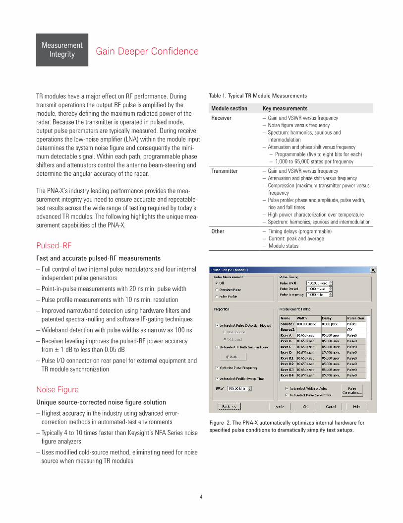
Pulsed-RF
Fast and accurate pulsed-RF measurements
– Full control of two internal pulse modulators and four internal
independent pulse generators
– Point-in-pulse measurements with 20 ns min. pulse width
– Pulse profile measurements with 10 ns min. resolution
– Improved narrowband detection using hardware filters and
patented spectral-nulling and software IF-gating techniques
– Wideband detection with pulse widths as narrow as 100 ns
– Receiver leveling improves the pulsed-RF power accuracy
from ± 1 dB to less than 0.05 dB
– Pulse I/O connector on rear panel for external equipment and
TR module synchronization
Noise Figure
Unique source-corrected noise figure solution
– Highest accuracy in the industry using advanced error-
correction methods in automated-test environments
– Typically 4 to 10 times faster than Keysight’s NFA Series noise
figure analyzers
– Uses modified cold-source method, eliminating need for noise
source when measuring TR modules
Module section Key measurements
Receiver – Gain and VSWR versus frequency
– Noise figure versus frequency
– Spectrum: harmonics, spurious and
intermodulation
– Attenuation and phase shift versus frequency
– Programmable (five to eight bits for each)
– 1,000 to 65,000 states per frequency
Transmitter – Gain and VSWR versus frequency
– Attenuation and phase shift versus frequency
– Compression (maximum transmitter power versus
frequency
– Pulse profile: phase and amplitude, pulse width,
rise and fall times
– High power characterization over temperature
– Spectrum: harmonics, spurious and intermodulation
Other – Timing delays (programmable)
– Current: peak and average
– Module status
Table 1. Typical TR Module Measurements
Figure 2. The PNA-X automatically optimizes internal hardware for
specified pulse conditions to dramatically simplify test setups.
Gain Deeper ConidenceMeasurement
Integrity
5
Maintain Measurement Accuracy
Gain Compression
Gain compression versus frequency measurements
– Guided calibration provides power and mismatch correction
– Complete device characterization with two-dimensional
sweeps
– Flexibility with a variety of compression methods—
compression from linear gain, maximum gain, X/Y
compression, compression from back-off, or compression
from saturation
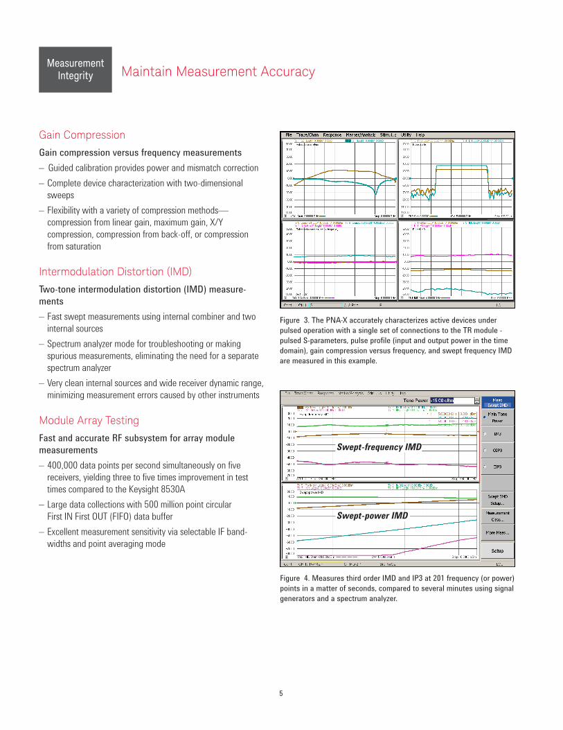
Intermodulation Distortion (IMD)
Two-tone intermodulation distortion (IMD) measure-
ments
– Fast swept measurements using internal combiner and two
internal sources
– Spectrum analyzer mode for troubleshooting or making
spurious measurements, eliminating the need for a separate
spectrum analyzer
– Very clean internal sources and wide receiver dynamic range,
minimizing measurement errors caused by other instruments
Module Array Testing
Fast and accurate RF subsystem for array module
measurements
– 400,000 data points per second simultaneously on five
receivers, yielding three to five times improvement in test
times compared to the Keysight 8530A
– Large data collections with 500 million point circular
First IN First OUT (FIFO) data buffer
– Excellent measurement sensitivity via selectable IF band-
widths and point averaging mode
Figure 4. Measures third order IMD and IP3 at 201 frequency (or power)
points in a matter of seconds, compared to several minutes using signal
generators and a spectrum analyzer.
Swept-frequency IMD
Swept-power IMD
Figure 3. The PNA-X accurately characterizes active devices under
pulsed operation with a single set of connections to the TR module -
pulsed S-parameters, pulse profile (input and output power in the time
domain), gain compression versus frequency, and swept frequency IMD
are measured in this example.
MeasurementIntegrity
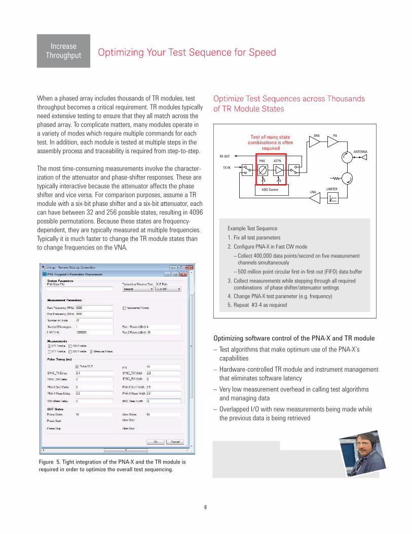
When a phased array includes thousands of TR modules, test
throughput becomes a critical requirement. TR modules typically
need extensive testing to ensure that they all match across the
phased array. To complicate matters, many modules operate in
a variety of modes which require multiple commands for each
test. In addition, each module is tested at multiple steps in the
assembly process and traceability is required from step-to-step.
The most time-consuming measurements involve the character-
ization of the attenuator and phase-shifter responses. These are
typically interactive because the attenuator affects the phase
shifter and vice versa. For comparison purposes, assume a TR
module with a six-bit phase shifter and a six-bit attenuator, each
can have between 32 and 256 possible states, resulting in 4096
possible permutations. Because these states are frequency-
dependent, they are typically measured at multiple frequencies.
Typically it is much faster to change the TR module states than
to change frequencies on the VNA.
Optimize Test Sequences across Thousands of TR Module States
Optimizing software control of the PNA-X and TR module
– Test algorithms that make optimum use of the PNA-X’s
capabilities
– Hardware-controlled TR module and instrument management
that eliminates software latency
– Very low measurement overhead in calling test algorithms
and managing data
– Overlapped I/O with new measurements being made while
the previous data is being retrieved
Figure 5. Tight integration of the PNA-X and the TR module is
required in order to optimize the overall test sequencing.
TALK TO AN EXPERT
Contact your local Keysight sales office for system integration and programming assistance.
6
ASIC ControlLNA
LIMITER
DRA PA
ATTNPHS
6
ANTENNA
TX IN
RX OUT
Test of many state combinations is often
required
Example Test Sequence
1. Fix all test parameters
2. Configure PNA-X in Fast CW mode
– Collect 400,000 data points/second on five measurement
channels simultaneously
– 500 million point circular first-in-first-out (FIFO) data buffer
3. Collect measurements while stepping through all required
combinations of phase shifter/attenuator settings
4. Change PNA-X test parameter (e.g. frequency)
5. Repeat #3-4 as required
6
Optimizing Your Test Sequence for SpeedIncrease
Throughput

7
During the development process, the engineering team performs
a very wide range of measurements. With a typical legacy test
platform, it could take more than 60 hours to perform such an
extensive set of measurements.
Clearly, 60-hour test times were not feasible in production and in
reality were an obstacle in engineering too. The simplest way to
achieve a shorter test time is to reduce the number of measure-
ments, especially for phase and attenuation.
The PNA-X is designed to be controlled for automated applica-
tions that enable test solutions to be optimized for throughput.
The example test platform data shown can perform complete
characterization of a TR module with 700,000-plus measure-
ments requiring an average test time of less than 5 minutes.
Depending on the mix of measurements, the PNA-X based test
platform can perform an order of magnitude more measure-
ments in less than one-tenth the time required by the previous
legacy test systems. As a result, the overall speed improvement
is approximately two orders of magnitude
Providing the first one-box pulsed-RF test system, the PNA-X sets
a new standard for simplicity, speed, and accuracy
By the 1990s, the
HP 8510 was the
industry standard
for pulsed-RF
vector network
analyzers.
Table 2. The reduction of measurements to reduce test time on the legacy TR system is no longer required with the PNA-X
Legacy T/R Test System
PNA-X
T/R Test System
Ideal requirement Reduced for production Ideal requirement
Measurement Chan Pts Freqs Total Pts Freqs Total Pts Freqs Total
RCVR gain and VSWR 4 2 201 1608 2 201 1608 2 201 1608
RCVR noise figure 4 1 11 44 1 3 12 1 11 44
RCVR phase and attenuation 4 4096 21 344064 128 21 10752 4096 21 344064
RCVR spectrum 4 2048 1 8192 2048 1 8192 2048 1 8192
XMTR gain and VSWR 4 2 201 1608 2 201 1608 2 201 1608
XMTR phase and attenuation 4 4096 21 344064 128 21 10752 4096 21 344064
XMTR compression 4 1 201 804 1 3 12 1 201 804
XMTR pulse profile 4 20 1 80 20 1 80 20 1 80
Timing 4 24 1 96 24 1 96 24 1 96
Supply current 4 3 1 12 3 1 12 3 1 12
Module status 1 1 1 1 1 1 1 1 1 1
Total measurements 700,573 33,125 700,573
Approximate test time 60 hrs 30 min 5 min
Accelerating Throughput Eliminates the Need for Legacy TradeoffsIncrease Throughput

Beneits for Engineering
Using the PNA-X to achieve extremely high throughput opens
new capabilities to users in both production and engineering. For
engineering, very high-speed testing makes it possible to mea-
sure all module modes and parameters with fine resolution (use-
ful when looking for anomalies) in a few seconds. Engineers need
not make compromises between fast turnaround and the quantity
of data gathered. One positive consequence: this encourages
more thorough testing of extreme conditions (e.g., temperature,
shock and environmental) because the electrical parameters can
be measured quickly relative to variations in those conditions. The
large quantities of data gathered can also be used to improve
component modeling.
Managing the Total Cost of Ownership
Cost of ownership is always a hot topic when making a program
decision for any new upgrade or sustainment option. The Total
Cost of Ownership (TCO) is defined to be the total cost to own
and operate a piece of equipment over its useful life. TCO shows
how operating costs can be critical drivers in reducing total costs
beyond simply lowering acquisition (capital) costs. Keysight PNA-X
based test solutions offer the lowest cost of ownership with:
– 3 year warranty standard on all products, with options up to
5 years
– 12 month calibration intervals
– Code compatibility offering the option to re-use existing test code
– Test equipment that holds its value longer than any other test
and measurement company
Beneits for Production
For production, the most important improvement is a dramatic
reduction in test time. The ability to maintain the traceability of
test results from engineering through each step in production has
multiple benefits: it helps ensure delivery of a quality product,
and it improves the production process by helping determine
the sources of parameter variations. In addition, comprehensive
testing reduces the risk of shipping a module with one or more
anomalies. It also has the potential to improve yield through the
use of narrower tolerance bands because all data points are
measured. As a final benefit, comprehensive testing enables
sorting and matching of modules to meet special needs,
potentially at a premium price.
Figure 6. Keysight PNA-X based test solutions offer the lowest cost
of ownership in the test and measurement industry.
Figure 7. Calibration of the equipment (i.e. metrology) is usually the largest cost component of preventive maintenance expenses. In this regard,
calibration cycle period is the single largest lever to pull on to reduce such metrology costs.
8
CalibrationOtheroperating
Training &education
Technologyrefresh
Repair
Downtimemitigation
Operating
expenses
Capital
expenses
Common Test Platform Across All Phases of Product IntegrationReduce Cost
of Test
KeysightKeysightKeysight
9
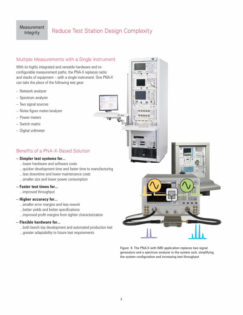
Multiple Measurements with a Single Instrument
With its highly integrated and versatile hardware and re-
configurable measurement paths, the PNA-X replaces racks
and stacks of equipment – with a single instrument. One PNA-X
can take the place of the following test gear:
– Network analyzer
– Spectrum analyzer
– Two signal sources
– Noise figure meter/analyzer
– Power meters
– Switch matrix
– Digital voltmeter
Beneits of a PNA-X-Based Solution
– Simpler test systems for…
…lower hardware and software costs
…quicker development time and faster time to manufacturing
…less downtime and lower maintenance costs
…smaller size and lower power consumption
– Faster test times for…
…improved throughput
– Higher accuracy for…
…smaller error margins and less rework
…better yields and better specifications
…improved profit margins from tighter characterization
– Flexible hardware for…
…both bench-top development and automated production test
…greater adaptability to future test requirements
Figure 8. The PNA-X with IMD application replaces two signal
generators and a spectrum analyzer in the system rack, simplifying
the system configuration and increasing test throughput
Reduce Test Station Design ComplexityMeasurement
Integrity
PNA-X - The Industry’s Most Advanced RF Test Solution
10
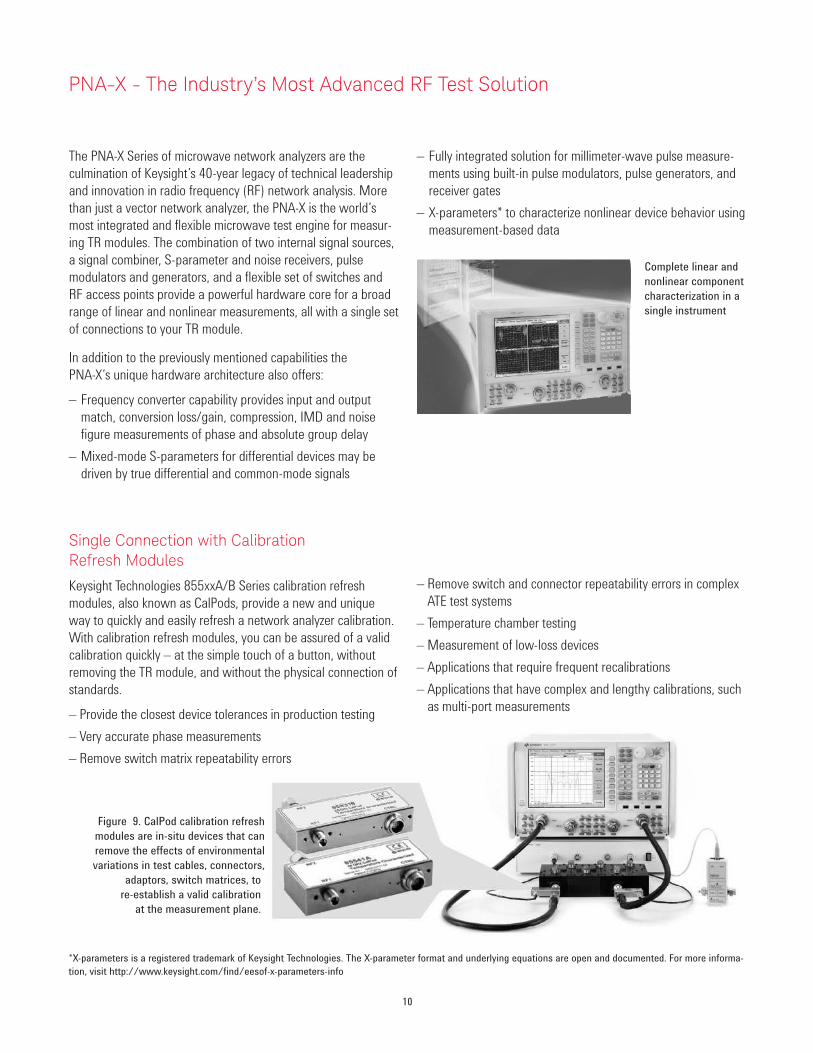
Complete linear and
nonlinear component
characterization in a
single instrument
*X-parameters is a registered trademark of Keysight Technologies. The X-parameter format and underlying equations are open and documented. For more informa-
tion, visit http://www.keysight.com/find/eesof-x-parameters-info
Figure 9. CalPod calibration refresh
modules are in-situ devices that can
remove the effects of environmental
variations in test cables, connectors,
adaptors, switch matrices, to
re-establish a valid calibration
at the measurement plane.
The PNA-X Series of microwave network analyzers are the
culmination of Keysight’s 40-year legacy of technical leadership
and innovation in radio frequency (RF) network analysis. More
than just a vector network analyzer, the PNA-X is the world’s
most integrated and flexible microwave test engine for measur-
ing TR modules. The combination of two internal signal sources,
a signal combiner, S-parameter and noise receivers, pulse
modulators and generators, and a flexible set of switches and
RF access points provide a powerful hardware core for a broad
range of linear and nonlinear measurements, all with a single set
of connections to your TR module.
In addition to the previously mentioned capabilities the
PNA-X’s unique hardware architecture also offers:
– Frequency converter capability provides input and output
match, conversion loss/gain, compression, IMD and noise
figure measurements of phase and absolute group delay
– Mixed-mode S-parameters for differential devices may be
driven by true differential and common-mode signals
Single Connection with Calibration Refresh Modules
Keysight Technologies 855xxA/B Series calibration refresh
modules, also known as CalPods, provide a new and unique
way to quickly and easily refresh a network analyzer calibration.
With calibration refresh modules, you can be assured of a valid
calibration quickly – at the simple touch of a button, without
removing the TR module, and without the physical connection of
standards.
– Provide the closest device tolerances in production testing
– Very accurate phase measurements
– Remove switch matrix repeatability errors
– Fully integrated solution for millimeter-wave pulse measure-
ments using built-in pulse modulators, pulse generators, and
receiver gates
– X-parameters* to characterize nonlinear device behavior using
measurement-based data
– Remove switch and connector repeatability errors in complex
ATE test systems
– Temperature chamber testing
– Measurement of low-loss devices
– Applications that require frequent recalibrations
– Applications that have complex and lengthy calibrations, such
as multi-port measurements
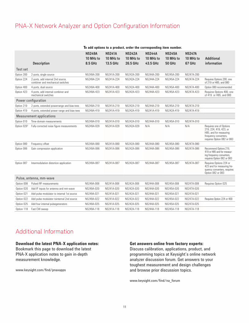
Description
N5249A
10 MHz to
8.5 GHz
N5241A
10 MHz to
13.5 GHz
N5242A
10 MHz to
26.5 GHz
N5244A
10 MHz to
43.5 GHz
N5245A
10 MHz to
50 GHz
N5247A
10 MHz to
67 GHz
Additional
information
Test set
Option 200 2-ports, single source N5249A-200 N5241A-200 N5242A-200 N5244A-200 N5245A-200 N5247A-200
Option 224 2-ports, add internal 2nd source, combiner and mechanical switches
N5249A-224 N5241A-224 N5242A-224 N5244A-224 N5245A-224 N5247A-224 Requires Options 200, one of 219 or H85, and 080
Option 400 4-ports, dual source N5249A-400 N5241A-400 N5242A-400 N5244A-400 N5245A-400 N5247A-400 Option 080 recommended
Option 423 4-ports, add internal combiner and mechanical switches
N5249A-423 N5241A-423 N5242A-423 N5244A-423 N5245A-423 N5247A-423 Requires Options 400, one of 419 or H85, and 080
Power conigurationOption 219 2-ports, extended powerrange and bias-tees N5249A-219 N5241A-219 N5242A-219 N5244A-219 N5245A-219 N5247A-219
Option 419 4-ports, extended power range and bias-tees N5249A-419 N5241A-419 N5242A-419 N5241A-419 N5242A-419 N5247A-419
Measurement applications
Option 010 Time-domain measurements N5249A-010 N5241A-010 N5242A-010 N5244A-010 N5245A-010 N5247A-010
Option 0292 Fully-corrected noise figure measurements N5249A-029 N5241A-029 N5242A-029 N/A N/A N/A Requires one of Options 219, 224, 419, 423, or H85, and for measuring frequency converters, requires Option 082 or 083
Option 080 Frequency offset N5249A-080 N5241A-080 N5242A-080 N5244A-080 N5245A-080 N5247A-080
Option 086 Gain compression application N5249A-086 N5241A-086 N5242A-086 N5244A-086 N5245A-086 N5247A-086 Recommend Options 219, 419 or H85 and for measur-ing frequency converters, requires Option 082 or 083
Option 087 Intermodulation distortion application N5249A-087 N5241A-087 N5242A-087 N5244A-087 N5245A-087 N5247A-087 Requires Options 224 or 423 and for measuring fre-quency converters, requires Option 082 or 083
Pulse, antenna, mm-wave
Option 008 Pulsed-RF measurements N5249A-008 N5241A-008 N5242A-008 N5244A-008 N5245A-008 N5247A-008 Requires Option 025
Option 020 Add IF inputs for antenna and mm-wave N5249A-020 N5241A-020 N5242A-020 N5244A-020 N5245A-020 N5247A-020
Option 021 Add pulse modulator to internal 1st source N5249A-021 N5241A-021 N5242A-021 N5244A-021 N5245A-021 N5247A-021
Option 022 Add pulse modulator tointernal 2nd source N5249A-022 N5241A-022 N5242A-022 N5244A-022 N5245A-022 N5247A-022 Requires Option 224 or 400
Option 025 Add four internal pulsegenerators N5249A-025 N5241A-025 N5242A-025 N5244A-025 N5245A-025 N5247A-025
Option 118 Fast CW sweep N5249A-118 N5241A-118 N5242A-118 N5244A-118 N5245A-118 N5247A-118
�o add options to a product, order the corresponding item number.
Download the latest PNA-X application notes:
Bookmark this page to download the latest
PNA-X application notes to gain in-depth
measurement knowledge.
www.keysight.com/find/pnaxapps
Get answers online from factory experts:
Discuss calibration, applications, product, and
programming topics at Keysight’s online network
analyzer discussion forum. Get answers to your
toughest measurement and design challenges
and browse prior discussion topics.
www.keysight.com/find/na_forum
Additional Information
11
PNA-X Network Analyzer and Option Coniguration Information

myKeysight
www.keysight.com/find/mykeysight
A personalized view into the information most relevant to you.
Three-Year Warranty
www.keysight.com/find/ThreeYearWarranty
Keysight’s commitment to superior product quality and lower total cost of ownership. The only test and measurement company with three-year
warranty standard on all instruments, worldwide.
Keysight Assurance Plans
www.keysight.com/find/AssurancePlans
Up to five years of protection and no budgetary surprises to ensure your
instruments are operating to specification so you can rely on accurate
measurements.
www.keysight.com/go/quality
Keysight Technologies, Inc.
DEKRA Certified ISO 9001:2008
Quality Management System
Keysight Channel Partners
www.keysight.com/find/channelpartners
Get the best of both worlds: Keysight’s measurement expertise and product breadth, combined with channel partner convenience.
www.keysight.com/find/pnax
For more information on Keysight
Technologies’ products, applications or services, please contact your local Keysight
office. The complete list is available at:
www.keysight.com/find/contactus
Americas
Canada (877) 894 4414Brazil 55 11 3351 7010Mexico 001 800 254 2440United States (800) 829 4444
Asia PaciicAustralia 1 800 629 485China 800 810 0189Hong Kong 800 938 693India 1 800 112 929Japan 0120 (421) 345Korea 080 769 0800Malaysia 1 800 888 848Singapore 1 800 375 8100Taiwan 0800 047 866Other AP Countries (65) 6375 8100
Europe & Middle East
Austria 0800 001122Belgium 0800 58580Finland 0800 523252France 0805 980333Germany 0800 6270999Ireland 1800 832700Israel 1 809 343051Italy 800 599100Luxembourg +32 800 58580Netherlands 0800 0233200Russia 8800 5009286Spain 0800 000154Sweden 0200 882255Switzerland 0800 805353
Opt. 1 (DE)Opt. 2 (FR)Opt. 3 (IT)
United Kingdom 0800 0260637
For other unlisted countries:
www.keysight.com/find/contactus
(BP-09-04-14)
12 | Keysight | Solutions for Transmit/Receive Module Test – Brochure
This information is subject to change without notice.© Keysight Technologies, 2014Published in USA, August 4, 20145991-3765ENwww.keysight.com
Recommended