JNCIA-Junos Study Guide—Part 2
1194 North Mathilda AvenueSunnyvale, CA 94089USA408-745-2000www.juniper.net
Worldwide Education ServicesWorldwide Education Services
This document is produced by Juniper Networks, Inc.
This document or any part thereof may not be reproduced or transmitted in any form under penalty of law, without the prior written permission of Juniper Networks Education Services.
Juniper Networks, Junos, Steel-Belted Radius, NetScreen, and ScreenOS are registered trademarks of Juniper Networks, Inc. in the United States and other countries. The Juniper Networks Logo, the Junos logo, and JunosE are trademarks of Juniper Networks, Inc. All other trademarks, service marks, registered
trademarks, or registered service marks are the property of their respective owners.JNCIA-Junos Study Guide—Part 2.
Copyright © 2012, Juniper Networks, Inc.
All rights reserved. Printed in USA.
The information in this document is current as of the date listed above.
The information in this document has been carefully verified and is believed to be accurate for software Release 12.1R1.9. Juniper Networks assumes no responsibilities for any inaccuracies that may appear in this document. In no event will Juniper Networks be liable for direct, indirect, special, exemplary, incidental or consequential damages resulting from any defect or omission in this document, even if advised of the possibility of such damages.
Juniper Networks reserves the right to change, modify, transfer, or otherwise revise this publication without notice.
YEAR 2000 NOTICE
Juniper Networks hardware and software products do not suffer from Year 2000 problems and hence are Year 2000 compliant. The Junos operating system has no known time-related limitations through the year 2038. However, the NTP application is known to have some difficulty in the year 2036.
SOFTWARE LICENSE
The terms and conditions for using Juniper Networks software are described in the software license provided with the software, or to the extent applicable, in an agreement executed between you and Juniper Networks, or Juniper Networks agent. By using Juniper Networks software, you indicate that you understand and agree to be bound by its license terms and conditions. Generally speaking, the software license restricts the manner in which you are permitted to use the Juniper Networks software, may contain prohibitions against certain uses, and may state conditions under which the license is automatically terminated. You should consult the software license for further details.

Contents • iii
Contents
Chapter 1: Routing Fundamentals. . . . . . . . . . . . . . . . . . . . . . . . . . . . . . . . . . . . . . . . . . . .1-1
Chapter 2: Routing Policy . . . . . . . . . . . . . . . . . . . . . . . . . . . . . . . . . . . . . . . . . . . . . . . . . . .2-1
Chapter 3: Firewall Filters . . . . . . . . . . . . . . . . . . . . . . . . . . . . . . . . . . . . . . . . . . . . . . . . . .3-1
Overview
Welcome to the JNCIA-Junos Study Guide—Part 2. The purpose of this guide is to help you prepare for your JN0-102 exam and achieve your JNCIA-Junos credential. The contents of this document are based on the Junos Routing Essentials course. This study guide provides students with foundational routing knowledge and configuration examples and includes an overview of general routing concepts, routing policy, and firewall filters.
Agenda
Chapter 1: Routing Fundamentals
Chapter 2: Routing Policy
Chapter 3: Firewall Filters
www.juniper.net iv
Document Conventions
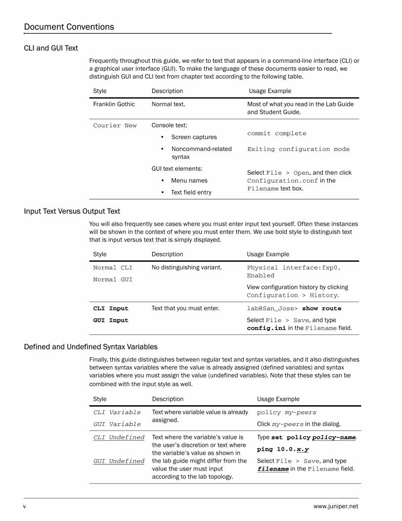
CLI and GUI TextFrequently throughout this guide, we refer to text that appears in a command-line interface (CLI) or a graphical user interface (GUI). To make the language of these documents easier to read, we distinguish GUI and CLI text from chapter text according to the following table.
Input Text Versus Output TextYou will also frequently see cases where you must enter input text yourself. Often these instances will be shown in the context of where you must enter them. We use bold style to distinguish text that is input versus text that is simply displayed.
Defined and Undefined Syntax VariablesFinally, this guide distinguishes between regular text and syntax variables, and it also distinguishes between syntax variables where the value is already assigned (defined variables) and syntax variables where you must assign the value (undefined variables). Note that these styles can be combined with the input style as well.
Style Description Usage Example
Franklin Gothic Normal text. Most of what you read in the Lab Guide and Student Guide.
Courier New Console text:
• Screen captures
• Noncommand-related syntax
GUI text elements:
• Menu names
• Text field entry
commit complete
Exiting configuration mode
Select File > Open, and then click Configuration.conf in the Filename text box.
Style Description Usage Example
Normal CLI
Normal GUI
No distinguishing variant. Physical interface:fxp0, Enabled
View configuration history by clicking Configuration > History.
CLI Input
GUI Input
Text that you must enter. lab@San_Jose> show route
Select File > Save, and type config.ini in the Filename field.
Style Description Usage Example
CLI Variable
GUI Variable
Text where variable value is already assigned.
policy my-peers
Click my-peers in the dialog.
CLI Undefined
GUI Undefined
Text where the variable’s value is the user’s discretion or text where the variable’s value as shown in the lab guide might differ from the value the user must input according to the lab topology.
Type set policy policy-name.
ping 10.0.x.y
Select File > Save, and type filename in the Filename field.
v www.juniper.net
Additional Information
Education Services Offerings
You can obtain information on the latest Education Services offerings, course dates, and class locations from the World Wide Web by pointing your Web browser to: http://www.juniper.net/training/education/.
About This Publication
The JNCIA-Junos Study Guide—Part 2 was developed and tested using software Release 12.1R1.9. Previous and later versions of software might behave differently so you should always consult the documentation and release notes for the version of code you are running before reporting errors.
This document is written and maintained by the Juniper Networks Education Services development team. Please send questions and suggestions for improvement to [email protected].
Technical Publications
You can print technical manuals and release notes directly from the Internet in a variety of formats:
• Go to http://www.juniper.net/techpubs/.
• Locate the specific software or hardware release and title you need, and choose the format in which you want to view or print the document.
Documentation sets and CDs are available through your local Juniper Networks sales office or account representative.
Juniper Networks Support
For technical support, contact Juniper Networks at http://www.juniper.net/customers/support/, or at 1-888-314-JTAC (within the United States) or 408-745-2121 (from outside the United States).
www.juniper.net vi
JNCIA-Junos Study Guide—Part 2
Chapter 1: Routing Fundamentals
This Chapter Discusses:• Basic routing operations and concepts;
• Routing and forwarding tables;
• Configuration and monitoring of static routing; and
• Configuration and monitoring of basic OSPF.
A Basic Definition of Routing
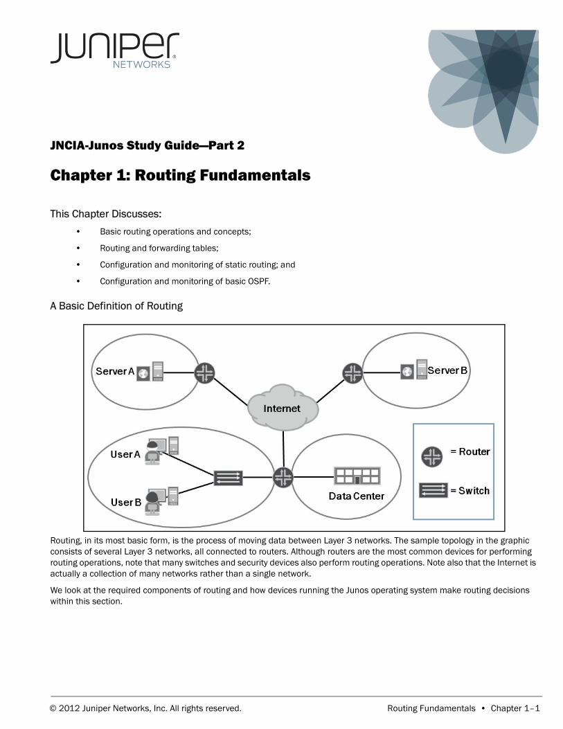
Routing, in its most basic form, is the process of moving data between Layer 3 networks. The sample topology in the graphic consists of several Layer 3 networks, all connected to routers. Although routers are the most common devices for performing routing operations, note that many switches and security devices also perform routing operations. Note also that the Internet is actually a collection of many networks rather than a single network.
We look at the required components of routing and how devices running the Junos operating system make routing decisions within this section.
© 2012 Juniper Networks, Inc. All rights reserved. Routing Fundamentals • Chapter 1–1
JNCIA-Junos Study Guide—Part 2
Routing Components
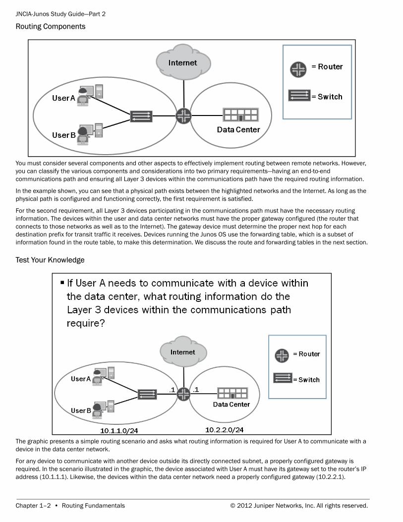
You must consider several components and other aspects to effectively implement routing between remote networks. However, you can classify the various components and considerations into two primary requirements—having an end-to-end communications path and ensuring all Layer 3 devices within the communications path have the required routing information.
In the example shown, you can see that a physical path exists between the highlighted networks and the Internet. As long as the physical path is configured and functioning correctly, the first requirement is satisfied.
For the second requirement, all Layer 3 devices participating in the communications path must have the necessary routing information. The devices within the user and data center networks must have the proper gateway configured (the router that connects to those networks as well as to the Internet). The gateway device must determine the proper next hop for each destination prefix for transit traffic it receives. Devices running the Junos OS use the forwarding table, which is a subset of information found in the route table, to make this determination. We discuss the route and forwarding tables in the next section.
Test Your Knowledge
The graphic presents a simple routing scenario and asks what routing information is required for User A to communicate with a device in the data center network.
For any device to communicate with another device outside its directly connected subnet, a properly configured gateway is required. In the scenario illustrated in the graphic, the device associated with User A must have its gateway set to the router’s IP address (10.1.1.1). Likewise, the devices within the data center network need a properly configured gateway (10.2.2.1).
Chapter 1–2 • Routing Fundamentals © 2012 Juniper Networks, Inc. All rights reserved.
JNCIA-Junos Study Guide—Part 2
The router, which functions as the gateway device for the user and data center networks, requires sufficient routing information to determine the proper next hop for the traffic sent between the connected networks. In this example, the router learns the required information by way of the interface configuration. The router adds the networks, in which the interfaces are participating, to the route and forwarding tables. The router consults its forwarding table to determine the actual next hop for received traffic.
Routing Information Sources
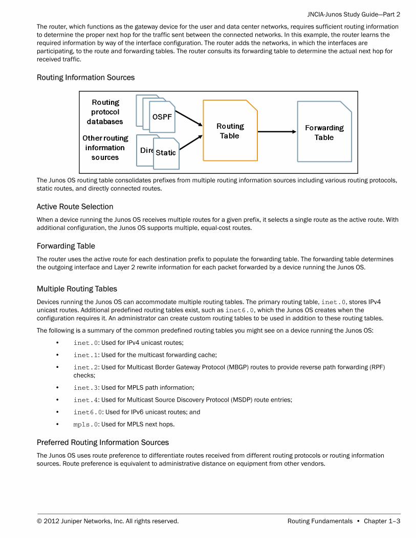
The Junos OS routing table consolidates prefixes from multiple routing information sources including various routing protocols, static routes, and directly connected routes.
Active Route SelectionWhen a device running the Junos OS receives multiple routes for a given prefix, it selects a single route as the active route. With additional configuration, the Junos OS supports multiple, equal-cost routes.
Forwarding TableThe router uses the active route for each destination prefix to populate the forwarding table. The forwarding table determines the outgoing interface and Layer 2 rewrite information for each packet forwarded by a device running the Junos OS.
Multiple Routing TablesDevices running the Junos OS can accommodate multiple routing tables. The primary routing table, inet.0, stores IPv4 unicast routes. Additional predefined routing tables exist, such as inet6.0, which the Junos OS creates when the configuration requires it. An administrator can create custom routing tables to be used in addition to these routing tables.
The following is a summary of the common predefined routing tables you might see on a device running the Junos OS:
• inet.0: Used for IPv4 unicast routes;
• inet.1: Used for the multicast forwarding cache;
• inet.2: Used for Multicast Border Gateway Protocol (MBGP) routes to provide reverse path forwarding (RPF) checks;
• inet.3: Used for MPLS path information;
• inet.4: Used for Multicast Source Discovery Protocol (MSDP) route entries;
• inet6.0: Used for IPv6 unicast routes; and
• mpls.0: Used for MPLS next hops.
Preferred Routing Information SourcesThe Junos OS uses route preference to differentiate routes received from different routing protocols or routing information sources. Route preference is equivalent to administrative distance on equipment from other vendors.
© 2012 Juniper Networks, Inc. All rights reserved. Routing Fundamentals • Chapter 1–3
JNCIA-Junos Study Guide—Part 2
Selecting the Active Route
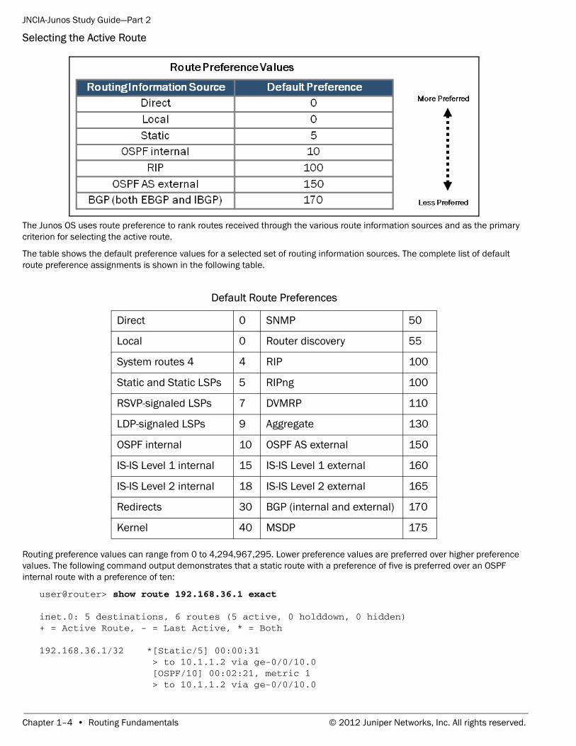
The Junos OS uses route preference to rank routes received through the various route information sources and as the primary criterion for selecting the active route.
The table shows the default preference values for a selected set of routing information sources. The complete list of default route preference assignments is shown in the following table.
Routing preference values can range from 0 to 4,294,967,295. Lower preference values are preferred over higher preference values. The following command output demonstrates that a static route with a preference of five is preferred over an OSPF internal route with a preference of ten:
user@router> show route 192.168.36.1 exact
inet.0: 5 destinations, 6 routes (5 active, 0 holddown, 0 hidden)+ = Active Route, - = Last Active, * = Both
192.168.36.1/32 *[Static/5] 00:00:31 > to 10.1.1.2 via ge-0/0/10.0 [OSPF/10] 00:02:21, metric 1 > to 10.1.1.2 via ge-0/0/10.0
Default Route Preferences
Direct 0 SNMP 50
Local 0 Router discovery 55
System routes 4 4 RIP 100
Static and Static LSPs 5 RIPng 100
RSVP-signaled LSPs 7 DVMRP 110
LDP-signaled LSPs 9 Aggregate 130
OSPF internal 10 OSPF AS external 150
IS-IS Level 1 internal 15 IS-IS Level 1 external 160
IS-IS Level 2 internal 18 IS-IS Level 2 external 165
Redirects 30 BGP (internal and external) 170
Kernel 40 MSDP 175
Chapter 1–4 • Routing Fundamentals © 2012 Juniper Networks, Inc. All rights reserved.
JNCIA-Junos Study Guide—Part 2
You can modify the default preference value for most routing information sources to make them more or less desirable. The exception is with direct and local routes, which are always preferred regardless of the modified route preference value associated with other routing information sources.
If equal-cost paths exist for the same destination, the routing protocol daemon (rpd) randomly selects one of the available paths. This approach provides load distribution among the paths while maintaining packet ordering per destination. The following output illustrates this point:
user@router> show route 10.1.0.0/16
inet.0: 10 destinations, 10 routes (10 active, 0 holddown, 0 hidden)+ = Active Route, - = Last Active, * = Both
10.1.1.0/24 *[Static/5] 00:00:25 to 172.20.66.2 via ge-0/0/2.0 > to 172.20.77.2 via ge-0/0/3.010.1.2.0/24 *[Static/5] 00:00:25 > to 172.20.66.2 via ge-0/0/2.0 to 172.20.77.2 via ge-0/0/3.010.1.3.0/24 *[Static/5] 00:00:25 to 172.20.66.2 via ge-0/0/2.0 > to 172.20.77.2 via ge-0/0/3.010.1.4.0/24 *[Static/5] 00:00:25 > to 172.20.66.2 via ge-0/0/2.0 to 172.20.77.2 via ge-0/0/3.0
If desired, you can enable per-flow load balancing over multiple equal-cost paths through routing policy. Load balancing is outside the scope of this class.
Viewing the Route Table
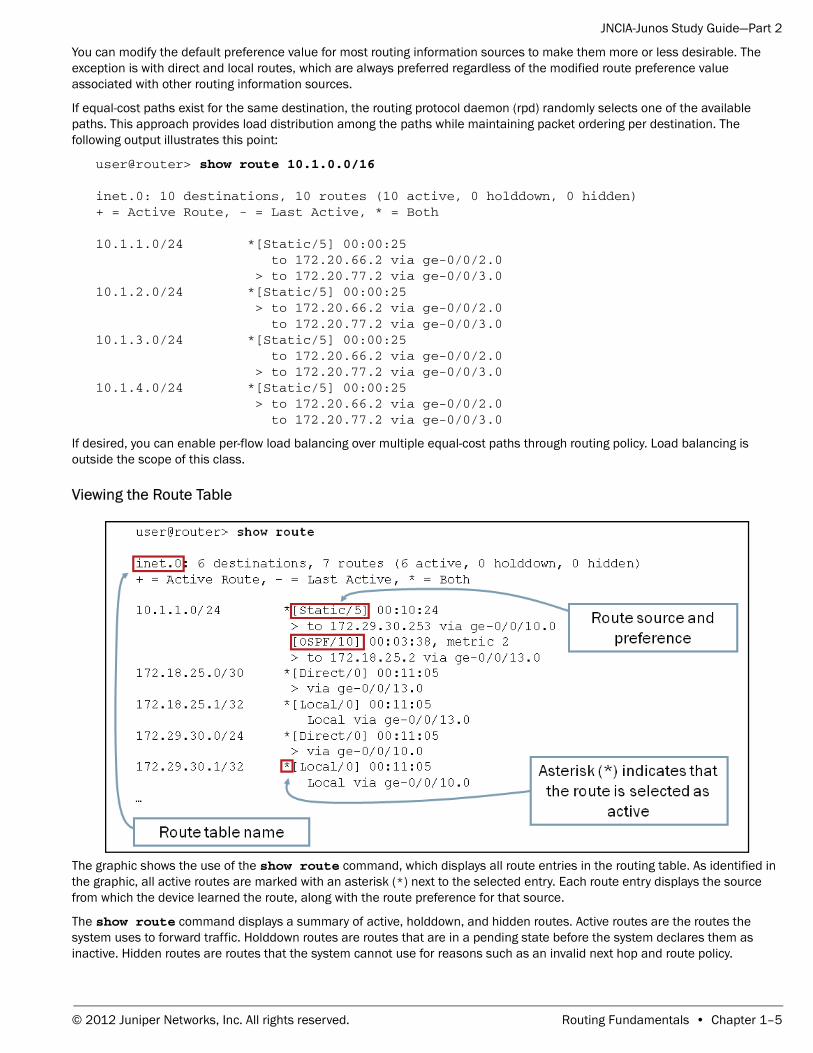
The graphic shows the use of the show route command, which displays all route entries in the routing table. As identified in the graphic, all active routes are marked with an asterisk (*) next to the selected entry. Each route entry displays the source from which the device learned the route, along with the route preference for that source.
The show route command displays a summary of active, holddown, and hidden routes. Active routes are the routes the system uses to forward traffic. Holddown routes are routes that are in a pending state before the system declares them as inactive. Hidden routes are routes that the system cannot use for reasons such as an invalid next hop and route policy.
© 2012 Juniper Networks, Inc. All rights reserved. Routing Fundamentals • Chapter 1–5
JNCIA-Junos Study Guide—Part 2
You can filter the generated output by destination prefix, protocol type, and other distinguishing attributes. The following sample capture illustrates the use of the protocol filtering option:
user@router> show route protocol ospf
inet.0: 6 destinations, 7 routes (6 active, 0 holddown, 0 hidden)+ = Active Route, - = Last Active, * = Both
10.1.1.0/24 [OSPF/10] 04:57:41, metric 2 > to 172.18.25.2 via ge-0/0/13.0224.0.0.5/32 *[OSPF/10] 05:00:58, metric 1 MultiRecv
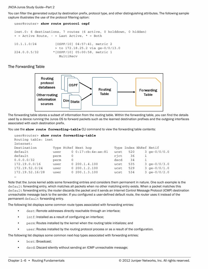
The Forwarding Table
The forwarding table stores a subset of information from the routing table. Within the forwarding table, you can find the details used by a device running the Junos OS to forward packets such as the learned destination prefixes and the outgoing interfaces associated with each destination prefix.
You use the show route forwarding-table CLI command to view the forwarding table contents:
user@router> show route forwarding-table Routing table: inetInternet:Destination Type RtRef Next hop Type Index NhRef Netifdefault user 0 0:17:cb:4e:ae:81 ucst 520 3 ge-0/0/0.0default perm 0 rjct 36 10.0.0.0/32 perm 0 dscd 34 1172.19.0.0/16 user 0 200.1.4.100 ucst 535 3 ge-0/0/3.0172.19.52.0/24 user 0 200.1.2.100 ucst 529 3 ge-0/0/1.0172.19.52.16/28 user 0 200.1.3.100 ucst 534 3 ge-0/0/2.0…
Note that the Junos kernel adds some forwarding entries and considers them permanent in nature. One such example is the default forwarding entry, which matches all packets when no other matching entry exists. When a packet matches this default forwarding entry, the router discards the packet and it sends an Internet Control Message Protocol (ICMP) destination unreachable message back to the sender. If you configured a user-defined default route, the router uses it instead of the permanent default forwarding entry.
The following list displays some common route types associated with forwarding entries:
• dest: Remote addresses directly reachable through an interface;
• intf: Installed as a result of configuring an interface;
• perm: Routes installed by the kernel when the routing table initializes; and
• user: Routes installed by the routing protocol process or as a result of the configuration.
The following list displays some common next-hop types associated with forwarding entries:
• bcst: Broadcast;
• dscd: Discard silently without sending an ICMP unreachable message;
Chapter 1–6 • Routing Fundamentals © 2012 Juniper Networks, Inc. All rights reserved.
JNCIA-Junos Study Guide—Part 2
• hold: Next hop is waiting to be resolved into a unicast or multicast type;
• locl: The local address on an interface;
• mcst: Wire multicast next hop (limited to the LAN);
• mdsc: Multicast discard;
• recv: Receive;
• rjct: Discard and send an ICMP unreachable message;
• ucst: Unicast; and
• ulst: A list of unicast next hops used when you configure load balancing.
Determining the Next Hop
When a packet enters a device running the Junos OS, it compares that packet against the entries within the forwarding table to determine the proper next hop. If the packet is destined to the local device, the Junos OS processes the packet locally. If the packet is destined to a remote device and a valid entry exists, the device running the Junos OS forwards the packet out the next-hop interface associated with the forwarding table entry.
If multiple destination prefixes match the packet’s destination, the Junos OS uses the most specific entry (also called longest match) when forwarding the packet to its destination.
In situations where no matching entry exists, the device running the Junos OS responds to the source device with a destination unreachable notification.
Test Your Knowledge
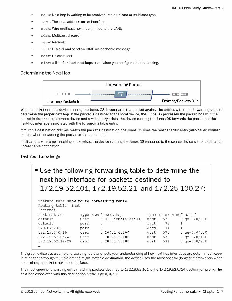
The graphic displays a sample forwarding table and tests your understanding of how next-hop interfaces are determined. Keep in mind that although multiple entries might match a destination, the device uses the most specific (longest match) entry when determining a packet’s next-hop interface.
The most specific forwarding entry matching packets destined to 172.19.52.101 is the 172.19.52.0/24 destination prefix. The next hop associated with this destination prefix is ge-0/0/1.0.
© 2012 Juniper Networks, Inc. All rights reserved. Routing Fundamentals • Chapter 1–7
JNCIA-Junos Study Guide—Part 2
The most specific forwarding entry matching packets destined to 172.19.52.21 is the 172.19.52.16/28 destination prefix. The next hop associated with this destination prefix is ge-0/0/2.0.
The only forwarding entry matching packets destined to 172.25.100.27 is the user-defined default forwarding entry. The next hop associated with the user-defined default forwarding entry is ge-0/0/0.0.
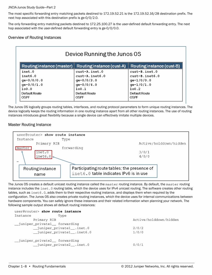
Overview of Routing Instances
The Junos OS logically groups routing tables, interfaces, and routing protocol parameters to form unique routing instances. The device logically keeps the routing information in one routing instance apart from all other routing instances. The use of routing instances introduces great flexibility because a single device can effectively imitate multiple devices.
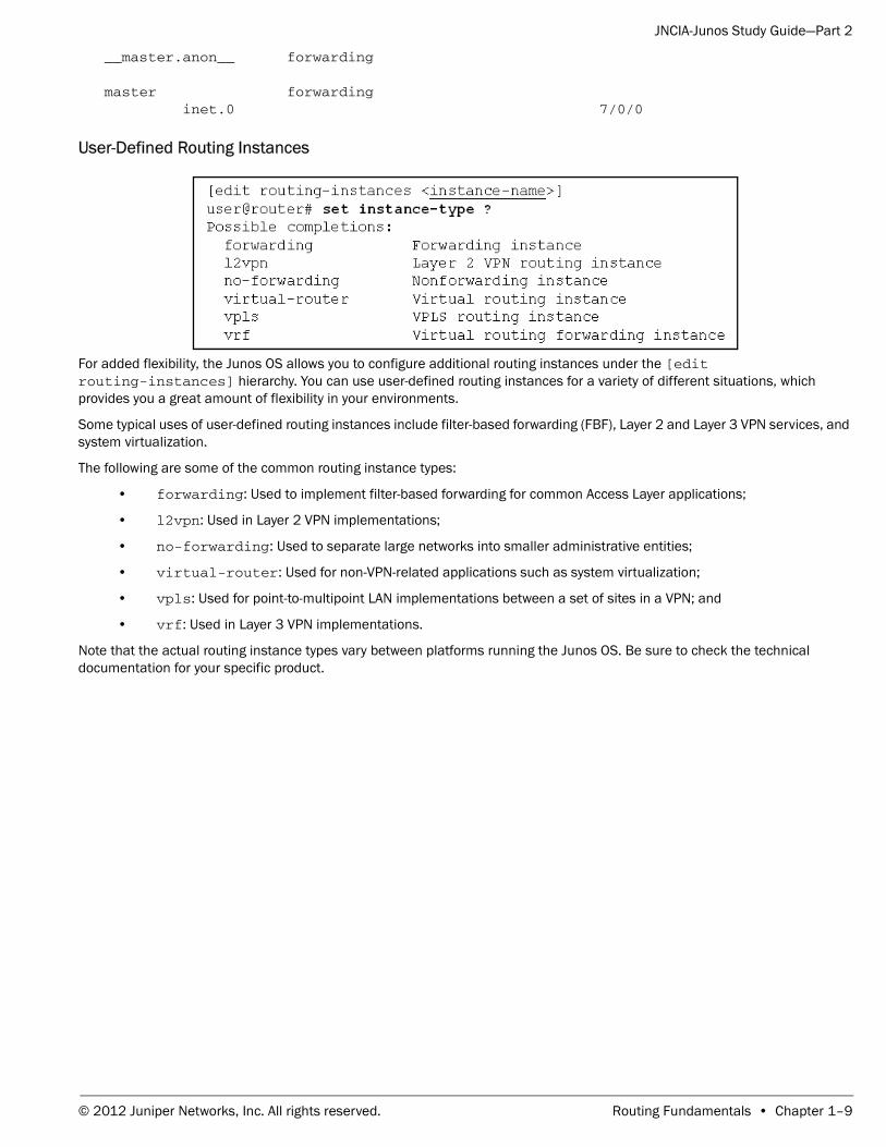
Master Routing Instance
The Junos OS creates a default unicast routing instance called the master routing instance. By default, the master routing instance includes the inet.0 routing table, which the device uses for IPv4 unicast routing. The software creates other routing tables, such as inet6.0, adds them to their respective routing instance, and displays them when required by the configuration. The Junos OS also creates private routing instances, which the device uses for internal communications between hardware components. You can safely ignore these instances and their related information when planning your network. The following sample output shows all default routing instances:
user@router> show route instance Instance Type Primary RIB Active/holddown/hidden__juniper_private1__ forwarding __juniper_private1__.inet.0 2/0/2 __juniper_private1__.inet6.0 1/0/0
__juniper_private2__ forwarding __juniper_private2__.inet.0 0/0/1
Chapter 1–8 • Routing Fundamentals © 2012 Juniper Networks, Inc. All rights reserved.
JNCIA-Junos Study Guide—Part 2
__master.anon__ forwarding
master forwarding inet.0 7/0/0
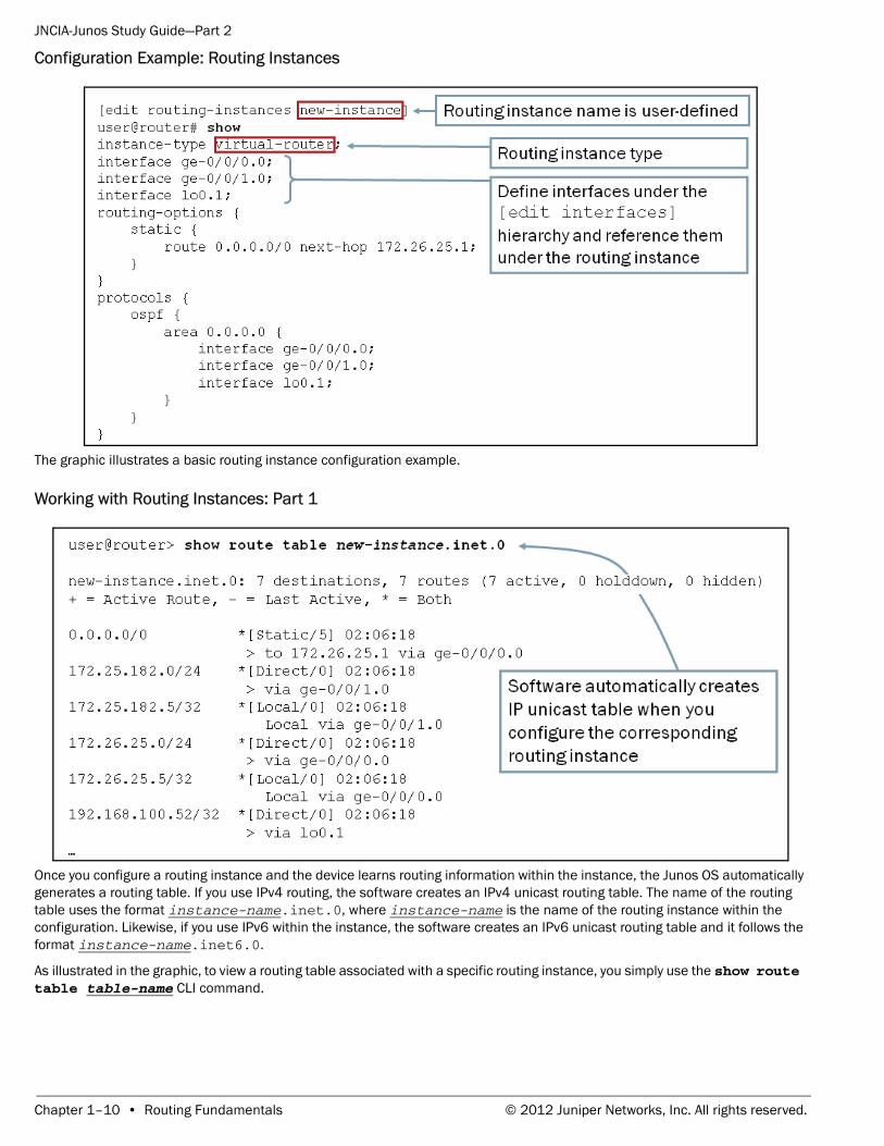
User-Defined Routing Instances
For added flexibility, the Junos OS allows you to configure additional routing instances under the [edit routing-instances] hierarchy. You can use user-defined routing instances for a variety of different situations, which provides you a great amount of flexibility in your environments.
Some typical uses of user-defined routing instances include filter-based forwarding (FBF), Layer 2 and Layer 3 VPN services, and system virtualization.
The following are some of the common routing instance types:
• forwarding: Used to implement filter-based forwarding for common Access Layer applications;
• l2vpn: Used in Layer 2 VPN implementations;
• no-forwarding: Used to separate large networks into smaller administrative entities;
• virtual-router: Used for non-VPN-related applications such as system virtualization;
• vpls: Used for point-to-multipoint LAN implementations between a set of sites in a VPN; and
• vrf: Used in Layer 3 VPN implementations.
Note that the actual routing instance types vary between platforms running the Junos OS. Be sure to check the technical documentation for your specific product.
© 2012 Juniper Networks, Inc. All rights reserved. Routing Fundamentals • Chapter 1–9
JNCIA-Junos Study Guide—Part 2
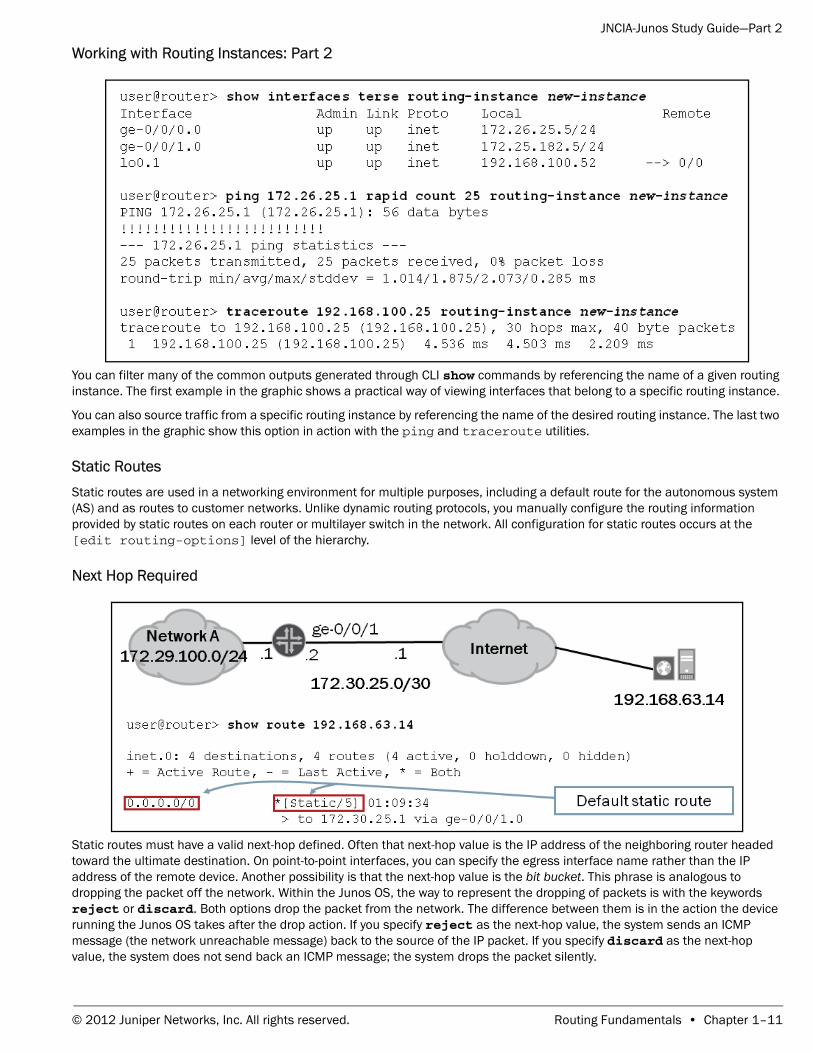
Configuration Example: Routing Instances
The graphic illustrates a basic routing instance configuration example.
Working with Routing Instances: Part 1
Once you configure a routing instance and the device learns routing information within the instance, the Junos OS automatically generates a routing table. If you use IPv4 routing, the software creates an IPv4 unicast routing table. The name of the routing table uses the format instance-name.inet.0, where instance-name is the name of the routing instance within the configuration. Likewise, if you use IPv6 within the instance, the software creates an IPv6 unicast routing table and it follows the format instance-name.inet6.0.
As illustrated in the graphic, to view a routing table associated with a specific routing instance, you simply use the show route table table-name CLI command.
Chapter 1–10 • Routing Fundamentals © 2012 Juniper Networks, Inc. All rights reserved.
JNCIA-Junos Study Guide—Part 2
Working with Routing Instances: Part 2
You can filter many of the common outputs generated through CLI show commands by referencing the name of a given routing instance. The first example in the graphic shows a practical way of viewing interfaces that belong to a specific routing instance.
You can also source traffic from a specific routing instance by referencing the name of the desired routing instance. The last two examples in the graphic show this option in action with the ping and traceroute utilities.
Static RoutesStatic routes are used in a networking environment for multiple purposes, including a default route for the autonomous system (AS) and as routes to customer networks. Unlike dynamic routing protocols, you manually configure the routing information provided by static routes on each router or multilayer switch in the network. All configuration for static routes occurs at the [edit routing-options] level of the hierarchy.
Next Hop Required
Static routes must have a valid next-hop defined. Often that next-hop value is the IP address of the neighboring router headed toward the ultimate destination. On point-to-point interfaces, you can specify the egress interface name rather than the IP address of the remote device. Another possibility is that the next-hop value is the bit bucket. This phrase is analogous to dropping the packet off the network. Within the Junos OS, the way to represent the dropping of packets is with the keywords reject or discard. Both options drop the packet from the network. The difference between them is in the action the device running the Junos OS takes after the drop action. If you specify reject as the next-hop value, the system sends an ICMP message (the network unreachable message) back to the source of the IP packet. If you specify discard as the next-hop value, the system does not send back an ICMP message; the system drops the packet silently.
© 2012 Juniper Networks, Inc. All rights reserved. Routing Fundamentals • Chapter 1–11
JNCIA-Junos Study Guide—Part 2
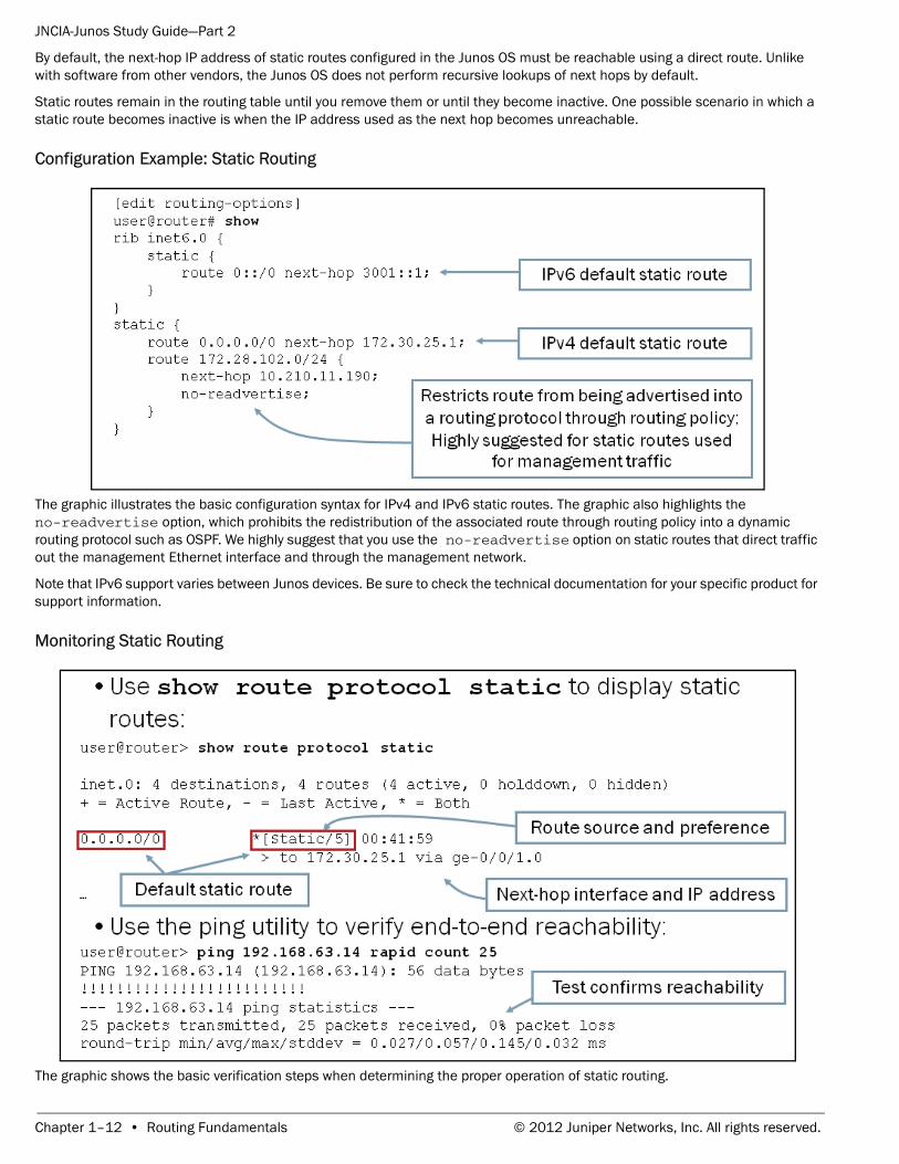
By default, the next-hop IP address of static routes configured in the Junos OS must be reachable using a direct route. Unlike with software from other vendors, the Junos OS does not perform recursive lookups of next hops by default.
Static routes remain in the routing table until you remove them or until they become inactive. One possible scenario in which a static route becomes inactive is when the IP address used as the next hop becomes unreachable.
Configuration Example: Static Routing
The graphic illustrates the basic configuration syntax for IPv4 and IPv6 static routes. The graphic also highlights the no-readvertise option, which prohibits the redistribution of the associated route through routing policy into a dynamic routing protocol such as OSPF. We highly suggest that you use the no-readvertise option on static routes that direct traffic out the management Ethernet interface and through the management network.
Note that IPv6 support varies between Junos devices. Be sure to check the technical documentation for your specific product for support information.
Monitoring Static Routing
The graphic shows the basic verification steps when determining the proper operation of static routing.
Chapter 1–12 • Routing Fundamentals © 2012 Juniper Networks, Inc. All rights reserved.
JNCIA-Junos Study Guide—Part 2
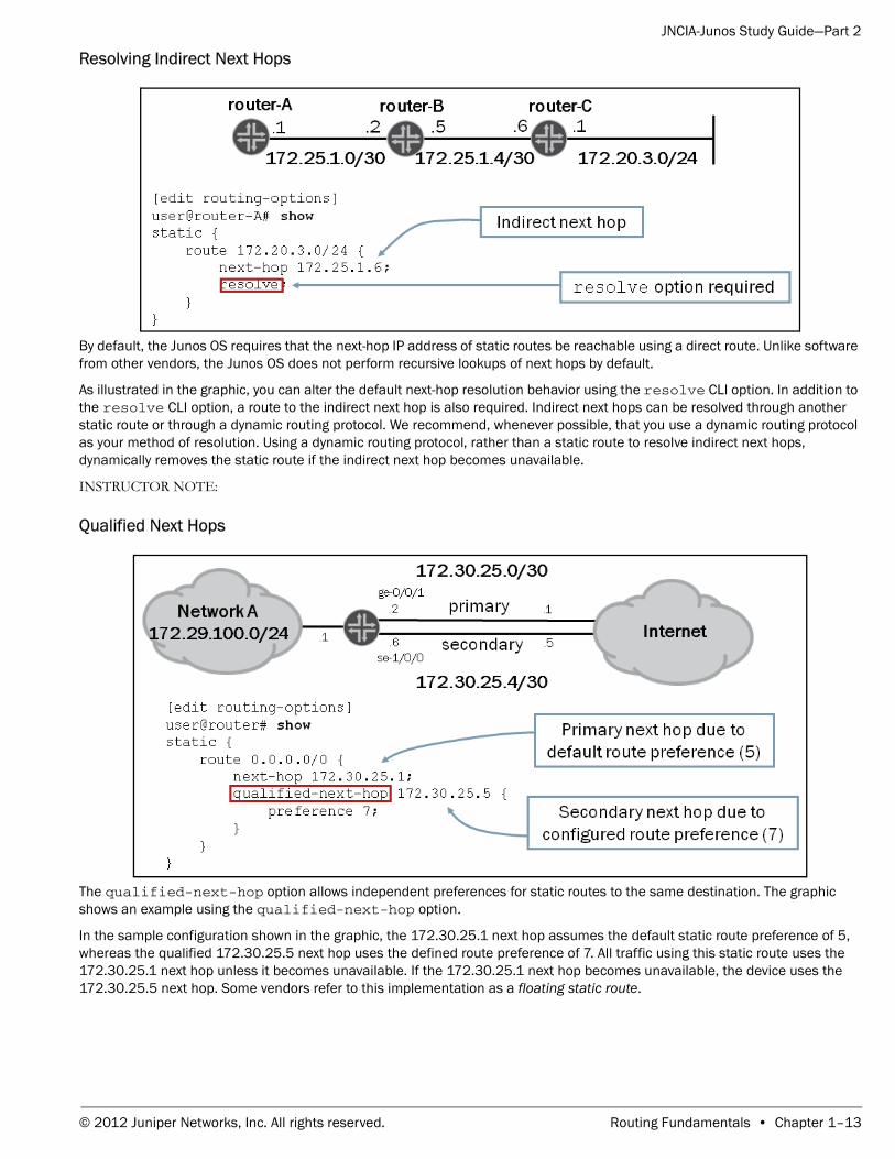
Resolving Indirect Next Hops
By default, the Junos OS requires that the next-hop IP address of static routes be reachable using a direct route. Unlike software from other vendors, the Junos OS does not perform recursive lookups of next hops by default.
As illustrated in the graphic, you can alter the default next-hop resolution behavior using the resolve CLI option. In addition to the resolve CLI option, a route to the indirect next hop is also required. Indirect next hops can be resolved through another static route or through a dynamic routing protocol. We recommend, whenever possible, that you use a dynamic routing protocol as your method of resolution. Using a dynamic routing protocol, rather than a static route to resolve indirect next hops, dynamically removes the static route if the indirect next hop becomes unavailable.
INSTRUCTOR NOTE:
Qualified Next Hops
The qualified-next-hop option allows independent preferences for static routes to the same destination. The graphic shows an example using the qualified-next-hop option.
In the sample configuration shown in the graphic, the 172.30.25.1 next hop assumes the default static route preference of 5, whereas the qualified 172.30.25.5 next hop uses the defined route preference of 7. All traffic using this static route uses the 172.30.25.1 next hop unless it becomes unavailable. If the 172.30.25.1 next hop becomes unavailable, the device uses the 172.30.25.5 next hop. Some vendors refer to this implementation as a floating static route.
© 2012 Juniper Networks, Inc. All rights reserved. Routing Fundamentals • Chapter 1–13
JNCIA-Junos Study Guide—Part 2
Dynamic Routing Static routing is ideal in small networks where only a few routes exist or in networks where absolute control of routing is necessary. However, static routing has certain drawbacks that might make it cumbersome and hard to manage in large environments where growth and change are constant. For large networks or networks that change regularly, dynamic routing might be the best option.
With dynamic routing, you simply configure the network interfaces to participate in a routing protocol. Devices running routing protocols can dynamically learn routing information from each other. When a device adds or removes routing information for a participating device, all other devices automatically update.
Benefits of Dynamic RoutingDynamic routing resolves many of the limitations and drawbacks of static routing. Some of the general benefits of dynamic routing include:
• Lower administrative overhead: The device learns routing information automatically, which eliminates the need for manual route definition;
• Increased network availability: During failure situations, dynamic routing can reroute traffic around the failure automatically (the ability to react to failures when they occur can provide increased network uptime); and
• Greater network scalability: The device easily manages network growth by dynamically learning routes and calculating the best paths through a network.
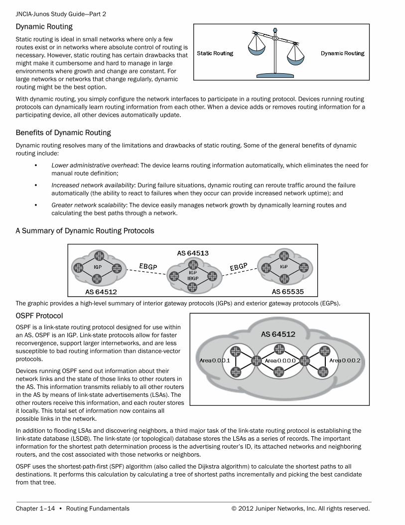
A Summary of Dynamic Routing Protocols
The graphic provides a high-level summary of interior gateway protocols (IGPs) and exterior gateway protocols (EGPs).
OSPF Protocol OSPF is a link-state routing protocol designed for use within an AS. OSPF is an IGP. Link-state protocols allow for faster reconvergence, support larger internetworks, and are less susceptible to bad routing information than distance-vector protocols.
Devices running OSPF send out information about their network links and the state of those links to other routers in the AS. This information transmits reliably to all other routers in the AS by means of link-state advertisements (LSAs). The other routers receive this information, and each router stores it locally. This total set of information now contains all possible links in the network.
In addition to flooding LSAs and discovering neighbors, a third major task of the link-state routing protocol is establishing the link-state database (LSDB). The link-state (or topological) database stores the LSAs as a series of records. The important information for the shortest path determination process is the advertising router’s ID, its attached networks and neighboring routers, and the cost associated with those networks or neighbors.
OSPF uses the shortest-path-first (SPF) algorithm (also called the Dijkstra algorithm) to calculate the shortest paths to all destinations. It performs this calculation by calculating a tree of shortest paths incrementally and picking the best candidate from that tree.
Chapter 1–14 • Routing Fundamentals © 2012 Juniper Networks, Inc. All rights reserved.
JNCIA-Junos Study Guide—Part 2
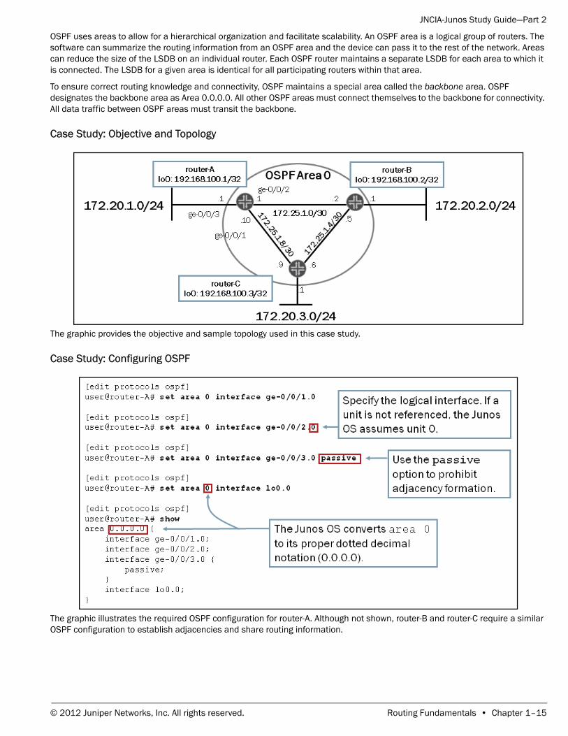
OSPF uses areas to allow for a hierarchical organization and facilitate scalability. An OSPF area is a logical group of routers. The software can summarize the routing information from an OSPF area and the device can pass it to the rest of the network. Areas can reduce the size of the LSDB on an individual router. Each OSPF router maintains a separate LSDB for each area to which it is connected. The LSDB for a given area is identical for all participating routers within that area.
To ensure correct routing knowledge and connectivity, OSPF maintains a special area called the backbone area. OSPF designates the backbone area as Area 0.0.0.0. All other OSPF areas must connect themselves to the backbone for connectivity. All data traffic between OSPF areas must transit the backbone.
Case Study: Objective and Topology
The graphic provides the objective and sample topology used in this case study.
Case Study: Configuring OSPF
The graphic illustrates the required OSPF configuration for router-A. Although not shown, router-B and router-C require a similar OSPF configuration to establish adjacencies and share routing information.
© 2012 Juniper Networks, Inc. All rights reserved. Routing Fundamentals • Chapter 1–15
JNCIA-Junos Study Guide—Part 2
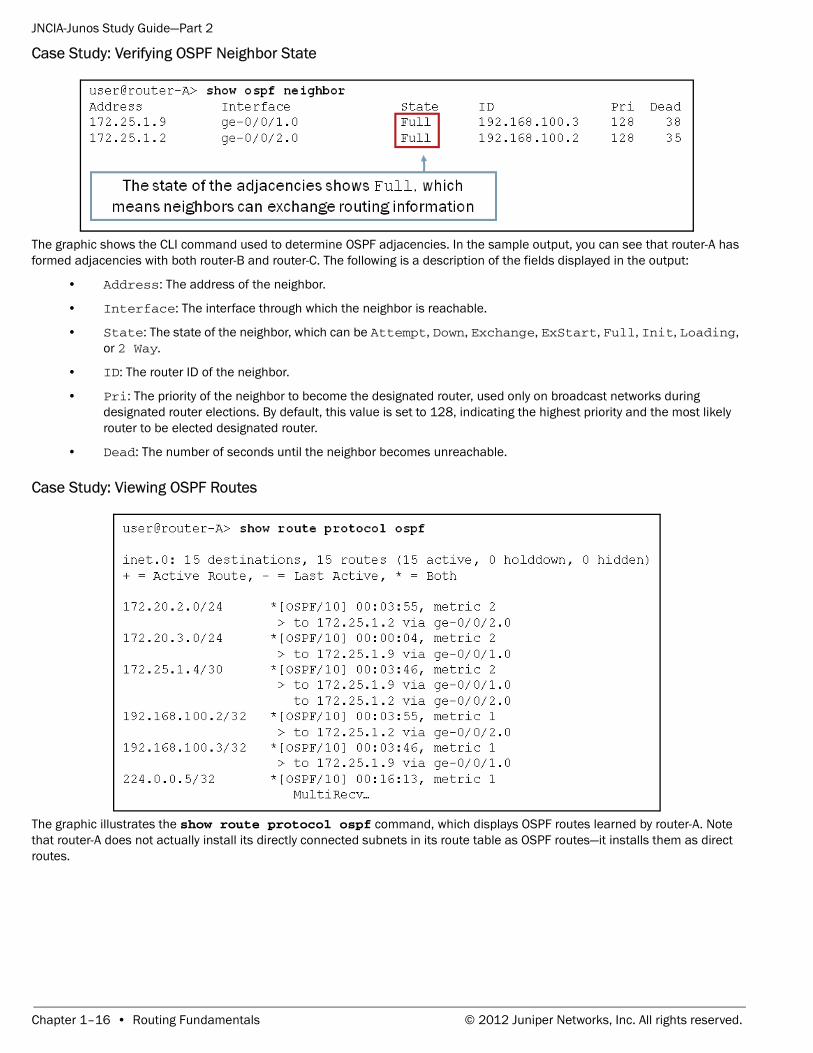
Case Study: Verifying OSPF Neighbor State
The graphic shows the CLI command used to determine OSPF adjacencies. In the sample output, you can see that router-A has formed adjacencies with both router-B and router-C. The following is a description of the fields displayed in the output:
• Address: The address of the neighbor.
• Interface: The interface through which the neighbor is reachable.
• State: The state of the neighbor, which can be Attempt, Down, Exchange, ExStart, Full, Init, Loading, or 2 Way.
• ID: The router ID of the neighbor.
• Pri: The priority of the neighbor to become the designated router, used only on broadcast networks during designated router elections. By default, this value is set to 128, indicating the highest priority and the most likely router to be elected designated router.
• Dead: The number of seconds until the neighbor becomes unreachable.
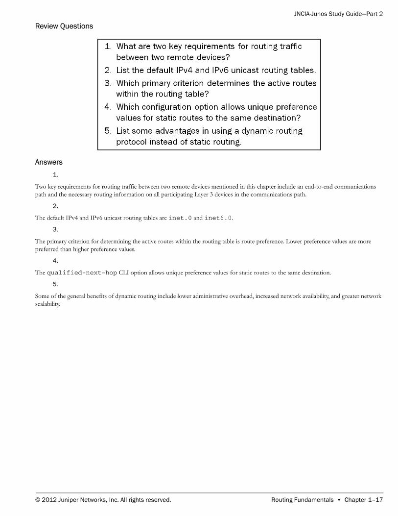
Case Study: Viewing OSPF Routes
The graphic illustrates the show route protocol ospf command, which displays OSPF routes learned by router-A. Note that router-A does not actually install its directly connected subnets in its route table as OSPF routes—it installs them as direct routes.
Chapter 1–16 • Routing Fundamentals © 2012 Juniper Networks, Inc. All rights reserved.
JNCIA-Junos Study Guide—Part 2
Review Questions
Answers1.
Two key requirements for routing traffic between two remote devices mentioned in this chapter include an end-to-end communications path and the necessary routing information on all participating Layer 3 devices in the communications path.
2.
The default IPv4 and IPv6 unicast routing tables are inet.0 and inet6.0.
3.
The primary criterion for determining the active routes within the routing table is route preference. Lower preference values are more preferred than higher preference values.
4.
The qualified-next-hop CLI option allows unique preference values for static routes to the same destination.
5.
Some of the general benefits of dynamic routing include lower administrative overhead, increased network availability, and greater network scalability.
© 2012 Juniper Networks, Inc. All rights reserved. Routing Fundamentals • Chapter 1–17
JNCIA-Junos Study Guide—Part 2
Chapter 2: Routing Policy
This Chapter Discusses:• The framework of routing policies;
• Routing policy evaluation;
• Typical usage scenarios for routing policy; and
• Configuration and application of a routing policy.
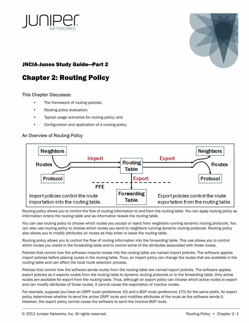
An Overview of Routing Policy
Routing policy allows you to control the flow of routing information to and from the routing table. You can apply routing policy as information enters the routing table and as information leaves the routing table.
You can use routing policy to choose which routes you accept or reject from neighbors running dynamic routing protocols. You can also use routing policy to choose which routes you send to neighbors running dynamic routing protocols. Routing policy also allows you to modify attributes on routes as they enter or leave the routing table.
Routing policy allows you to control the flow of routing information into the forwarding table. This use allows you to control which routes you install in the forwarding table and to control some of the attributes associated with those routes.
Policies that control how the software imports routes into the routing table are named import policies. The software applies import policies before placing routes in the routing table. Thus, an import policy can change the routes that are available in the routing table and can affect the local route selection process.
Policies that control how the software sends routes from the routing table are named export policies. The software applies export policies as it exports routes from the routing table to dynamic routing protocols or to the forwarding table. Only active routes are available for export from the routing table. Thus, although an export policy can choose which active routes to export and can modify attributes of those routes, it cannot cause the exportation of inactive routes.
For example, suppose you have an OSPF route (preference 10) and a BGP route (preference 170) for the same prefix. An export policy determines whether to send the active OSPF route and modifies attributes of the route as the software sends it. However, the export policy cannot cause the software to send the inactive BGP route.
© 2012 Juniper Networks, Inc. All rights reserved. Routing Policy • Chapter 2–1
JNCIA-Junos Study Guide—Part 2
The Junos operating system applies export policies as it exports routes from the routing table, so attribute changes do not affect the local routing table; rather, the software applies them to the route while exporting it.
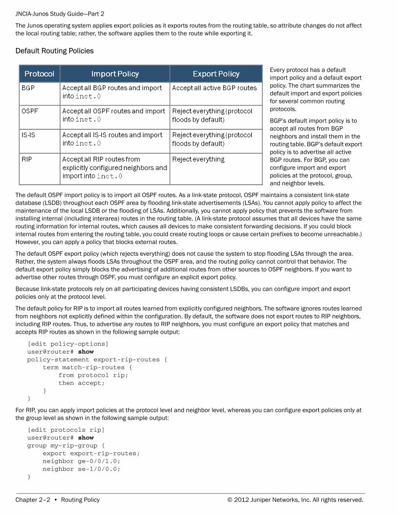
Default Routing Policies
Every protocol has a default import policy and a default export policy. The chart summarizes the default import and export policies for several common routing protocols.
BGP’s default import policy is to accept all routes from BGP neighbors and install them in the routing table. BGP’s default export policy is to advertise all active BGP routes. For BGP, you can configure import and export policies at the protocol, group, and neighbor levels.
The default OSPF import policy is to import all OSPF routes. As a link-state protocol, OSPF maintains a consistent link-state database (LSDB) throughout each OSPF area by flooding link-state advertisements (LSAs). You cannot apply policy to affect the maintenance of the local LSDB or the flooding of LSAs. Additionally, you cannot apply policy that prevents the software from installing internal (including interarea) routes in the routing table. (A link-state protocol assumes that all devices have the same routing information for internal routes, which causes all devices to make consistent forwarding decisions. If you could block internal routes from entering the routing table, you could create routing loops or cause certain prefixes to become unreachable.) However, you can apply a policy that blocks external routes.
The default OSPF export policy (which rejects everything) does not cause the system to stop flooding LSAs through the area. Rather, the system always floods LSAs throughout the OSPF area, and the routing policy cannot control that behavior. The default export policy simply blocks the advertising of additional routes from other sources to OSPF neighbors. If you want to advertise other routes through OSPF, you must configure an explicit export policy.
Because link-state protocols rely on all participating devices having consistent LSDBs, you can configure import and export policies only at the protocol level.
The default policy for RIP is to import all routes learned from explicitly configured neighbors. The software ignores routes learned from neighbors not explicitly defined within the configuration. By default, the software does not export routes to RIP neighbors, including RIP routes. Thus, to advertise any routes to RIP neighbors, you must configure an export policy that matches and accepts RIP routes as shown in the following sample output:
[edit policy-options]user@router# show policy-statement export-rip-routes { term match-rip-routes { from protocol rip; then accept; }}
For RIP, you can apply import policies at the protocol level and neighbor level, whereas you can configure export policies only at the group level as shown in the following sample output:
[edit protocols rip]user@router# show group my-rip-group { export export-rip-routes; neighbor ge-0/0/1.0; neighbor se-1/0/0.0;}
Chapter 2–2 • Routing Policy © 2012 Juniper Networks, Inc. All rights reserved.
JNCIA-Junos Study Guide—Part 2
Building Blocks of Routing Policy
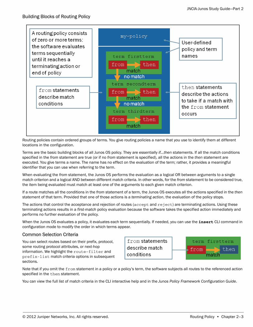
Routing policies contain ordered groups of terms. You give routing policies a name that you use to identify them at different locations in the configuration.
Terms are the basic building blocks of all Junos OS policy. They are essentially if...then statements. If all the match conditions specified in the from statement are true (or if no from statement is specified), all the actions in the then statement are executed. You give terms a name. The name has no effect on the evaluation of the term; rather, it provides a meaningful identifier that you can use when referring to the term.
When evaluating the from statement, the Junos OS performs the evaluation as a logical OR between arguments to a single match criterion and a logical AND between different match criteria. In other words, for the from statement to be considered true, the item being evaluated must match at least one of the arguments to each given match criterion.
If a route matches all the conditions in the from statement of a term, the Junos OS executes all the actions specified in the then statement of that term. Provided that one of those actions is a terminating action, the evaluation of the policy stops.
The actions that control the acceptance and rejection of routes (accept and reject) are terminating actions. Using these terminating actions results in a first-match policy evaluation because the software takes the specified action immediately and performs no further evaluation of the policy.
When the Junos OS evaluates a policy, it evaluates each term sequentially. If needed, you can use the insert CLI command in configuration mode to modify the order in which terms appear.
Common Selection Criteria You can select routes based on their prefix, protocol, some routing protocol attributes, or next-hop information. We highlight the route-filter and prefix-list match criteria options in subsequent sections.
Note that if you omit the from statement in a policy or a policy’s term, the software subjects all routes to the referenced action specified in the then statement.
You can view the full list of match criteria in the CLI interactive help and in the Junos Policy Framework Configuration Guide.
© 2012 Juniper Networks, Inc. All rights reserved. Routing Policy • Chapter 2–3
JNCIA-Junos Study Guide—Part 2
Prefix Lists
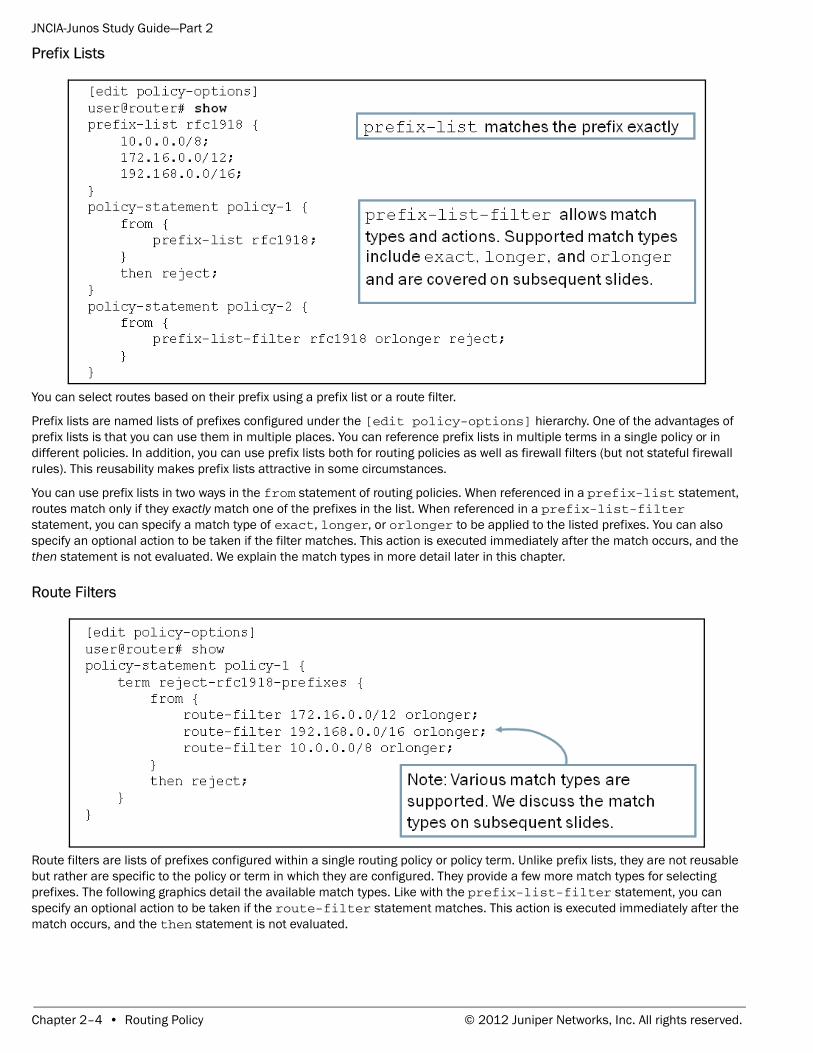
You can select routes based on their prefix using a prefix list or a route filter.
Prefix lists are named lists of prefixes configured under the [edit policy-options] hierarchy. One of the advantages of prefix lists is that you can use them in multiple places. You can reference prefix lists in multiple terms in a single policy or in different policies. In addition, you can use prefix lists both for routing policies as well as firewall filters (but not stateful firewall rules). This reusability makes prefix lists attractive in some circumstances.
You can use prefix lists in two ways in the from statement of routing policies. When referenced in a prefix-list statement, routes match only if they exactly match one of the prefixes in the list. When referenced in a prefix-list-filter statement, you can specify a match type of exact, longer, or orlonger to be applied to the listed prefixes. You can also specify an optional action to be taken if the filter matches. This action is executed immediately after the match occurs, and the then statement is not evaluated. We explain the match types in more detail later in this chapter.
Route Filters
Route filters are lists of prefixes configured within a single routing policy or policy term. Unlike prefix lists, they are not reusable but rather are specific to the policy or term in which they are configured. They provide a few more match types for selecting prefixes. The following graphics detail the available match types. Like with the prefix-list-filter statement, you can specify an optional action to be taken if the route-filter statement matches. This action is executed immediately after the match occurs, and the then statement is not evaluated.
Chapter 2–4 • Routing Policy © 2012 Juniper Networks, Inc. All rights reserved.
JNCIA-Junos Study Guide—Part 2
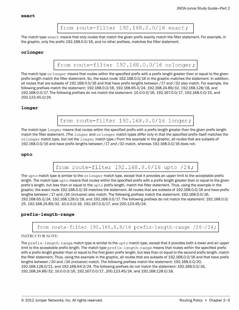
exact
The match type exact means that only routes that match the given prefix exactly match the filter statement. For example, in the graphic, only the prefix 192.168.0.0/16, and no other prefixes, matches the filter statement.
orlonger
The match type orlonger means that routes within the specified prefix with a prefix length greater than or equal to the given prefix length match the filter statement. So, the exact route 192.168.0.0/16 in the graphic matches the statement. In addition, all routes that are subsets of 192.168.0.0/16 and that have prefix lengths between /17 and /32 also match. For example, the following prefixes match the statement: 192.168.0.0/16, 192.168.65.0/24, 192.168.24.89/32, 192.168.128/18, and 192.168.0.0/17. The following prefixes do not match the statement: 10.0.0.0/16, 192.167.0.0/17, 192.168.0.0/15, and 200.123.45.0/24.
longer
The match type longer means that routes within the specified prefix with a prefix length greater than the given prefix length match the filter statement. (The longer and orlonger match types differ only in that the specified prefix itself matches the orlonger match type, but not the longer match type.) From the example in the graphic, all routes that are subsets of 192.168.0.0/16 and have prefix lengths between /17 and /32 match, whereas 192.168.0.0/16 does not.
upto
The upto match type is similar to the orlonger match type, except that it provides an upper limit to the acceptable prefix length. The match type upto means that routes within the specified prefix with a prefix length greater than or equal to the given prefix’s length, but less than or equal to the upto prefix length, match the filter statement. Thus, using the example in the graphic, the exact route 192.168.0.0/16 matches the statement. All routes that are subsets of 192.168.0.0/16 and have prefix lengths between /17 and /24 (inclusive) also match. The following prefixes match the statement: 192.168.0.0/16, 192.168.65.0/24, 192.168.128.0/18, and 192.168.0.0/17. The following prefixes do not match the statement: 192.168.0.0/25, 192.168.24.89/32, 10.0.0.0/16, 192.167.0.0/17, and 200.123.45/24.
prefix-length-range
INSTRUCTOR NOTE:
The prefix-length-range match type is similar to the upto match type, except that it provides both a lower and an upper limit to the acceptable prefix length. The match type prefix-length-range means that routes within the specified prefix with a prefix length greater than or equal to the first given prefix length, but less than or equal to the second prefix length, match the filter statement. Thus, using the example in the graphic, all routes that are subsets of 192.168.0.0/16 and that have prefix lengths between /20 and /24 (inclusive) match. The following prefixes match the statement: 192.168.0.0/20, 192.168.128.0/21, and 192.168.64.0/24. The following prefixes do not match the statement: 192.168.0.0/16, 192.168.24.89/32, 10.0.0.0/16, 192.167.0.0/17, 200.123.45/24, and 192.168.128.0/18.
© 2012 Juniper Networks, Inc. All rights reserved. Routing Policy • Chapter 2–5
JNCIA-Junos Study Guide—Part 2
Route Filter Match Types
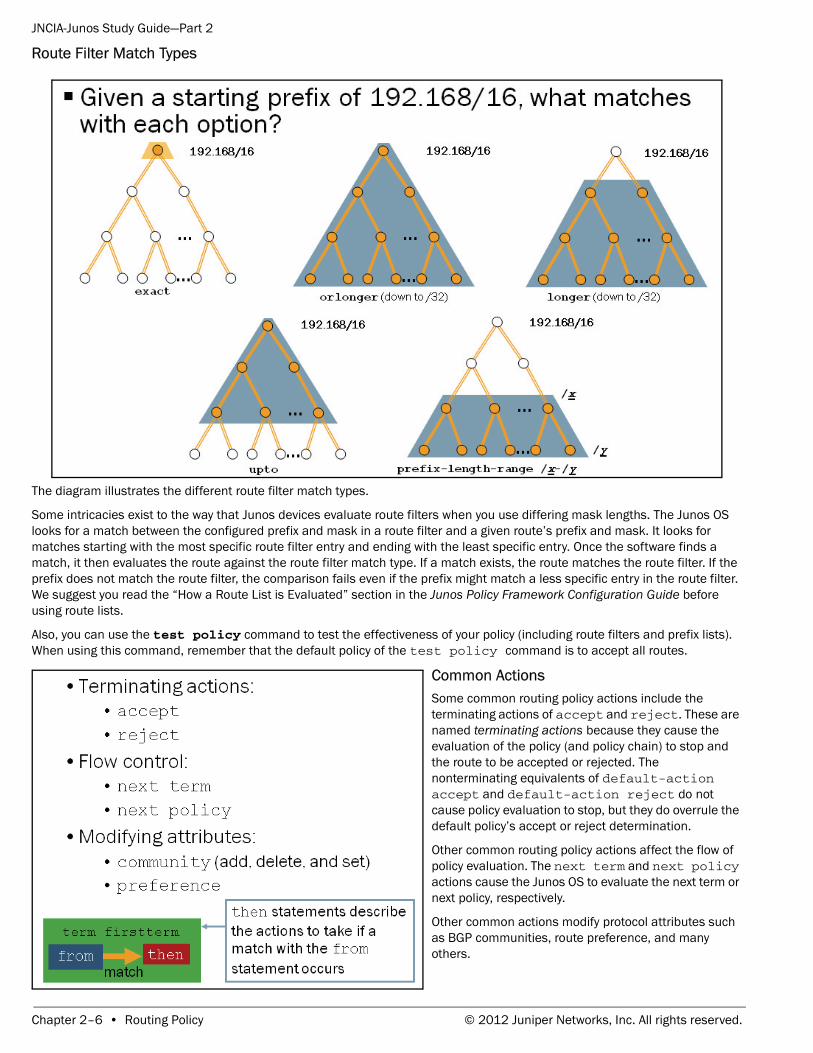
The diagram illustrates the different route filter match types.
Some intricacies exist to the way that Junos devices evaluate route filters when you use differing mask lengths. The Junos OS looks for a match between the configured prefix and mask in a route filter and a given route’s prefix and mask. It looks for matches starting with the most specific route filter entry and ending with the least specific entry. Once the software finds a match, it then evaluates the route against the route filter match type. If a match exists, the route matches the route filter. If the prefix does not match the route filter, the comparison fails even if the prefix might match a less specific entry in the route filter. We suggest you read the “How a Route List is Evaluated” section in the Junos Policy Framework Configuration Guide before using route lists.
Also, you can use the test policy command to test the effectiveness of your policy (including route filters and prefix lists). When using this command, remember that the default policy of the test policy command is to accept all routes.
Common Actions Some common routing policy actions include the terminating actions of accept and reject. These are named terminating actions because they cause the evaluation of the policy (and policy chain) to stop and the route to be accepted or rejected. The nonterminating equivalents of default-action accept and default-action reject do not cause policy evaluation to stop, but they do overrule the default policy’s accept or reject determination.
Other common routing policy actions affect the flow of policy evaluation. The next term and next policy actions cause the Junos OS to evaluate the next term or next policy, respectively.
Other common actions modify protocol attributes such as BGP communities, route preference, and many others.
Chapter 2–6 • Routing Policy © 2012 Juniper Networks, Inc. All rights reserved.
JNCIA-Junos Study Guide—Part 2
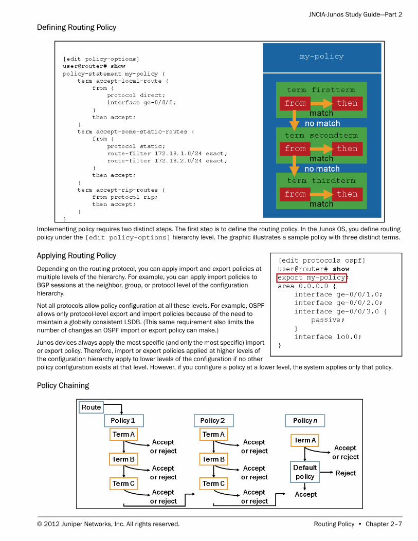
Defining Routing Policy
Implementing policy requires two distinct steps. The first step is to define the routing policy. In the Junos OS, you define routing policy under the [edit policy-options] hierarchy level. The graphic illustrates a sample policy with three distinct terms.
Applying Routing Policy Depending on the routing protocol, you can apply import and export policies at multiple levels of the hierarchy. For example, you can apply import policies to BGP sessions at the neighbor, group, or protocol level of the configuration hierarchy.
Not all protocols allow policy configuration at all these levels. For example, OSPF allows only protocol-level export and import policies because of the need to maintain a globally consistent LSDB. (This same requirement also limits the number of changes an OSPF import or export policy can make.)
Junos devices always apply the most specific (and only the most specific) import or export policy. Therefore, import or export policies applied at higher levels of the configuration hierarchy apply to lower levels of the configuration if no other policy configuration exists at that level. However, if you configure a policy at a lower level, the system applies only that policy.
Policy Chaining
© 2012 Juniper Networks, Inc. All rights reserved. Routing Policy • Chapter 2–7
JNCIA-Junos Study Guide—Part 2
You can cascade policies to form a chain of policy processing. You can create this chain of policies to solve a complex set of route manipulation tasks in a modular manner.
The Junos OS evaluates policies from left to right based on the order in which they are applied to a routing protocol. The Junos OS checks the match criteria of each policy and performs the associated action when a match occurs. If the first policy does not match or if the match is associated with a nonterminating action, the Junos OS evaluates the route against the next policy in the chain. This pattern repeats itself for all policies in the chain. The Junos OS ultimately applies the default policy for a given protocol when no terminating actions occur while evaluating the user-defined policy chain. We defined the default routing policies earlier in this chapter.
Policy processing stops once a route meets a terminating action—unless you are grouping policies with Boolean operators. Grouping policies for logical operations, such as AND or OR, is a subject that is beyond the scope of this class.
As previously mentioned, individual policies can comprise multiple terms. Terms are individual match and action pairs that you can name numerically or symbolically.
The Junos OS lists terms sequentially from top to bottom and evaluates them in that manner. The software checks each term for its match criteria. When a match occurs, the software performs the associated action. If no match exists in the first term, the software checks the second term. If no match exists in the second term, the Junos OS checks the third term. This pattern repeats itself for all terms. If no match exists in the last term, the Junos OS checks the next applied policy and then, eventually, the default policy for the protocol.
When it finds a match within a term, the Junos OS takes the corresponding action. If the action is a terminating action, the processing of the terms and the applied policies stops—otherwise processing continues.
The Junos OS also supports flow-control actions that affect the flow of policy evaluation. The next term and next policy actions cause the Junos OS to evaluate the next term or next policy, respectively.
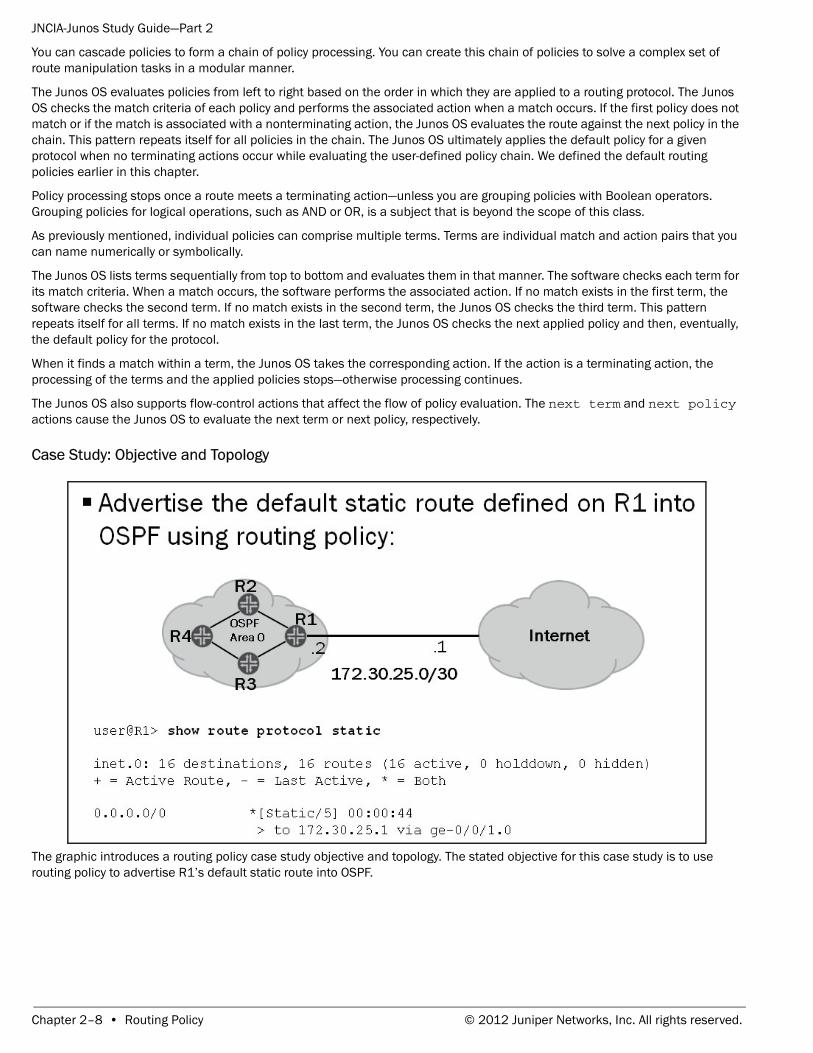
Case Study: Objective and Topology
The graphic introduces a routing policy case study objective and topology. The stated objective for this case study is to use routing policy to advertise R1’s default static route into OSPF.
Chapter 2–8 • Routing Policy © 2012 Juniper Networks, Inc. All rights reserved.
JNCIA-Junos Study Guide—Part 2
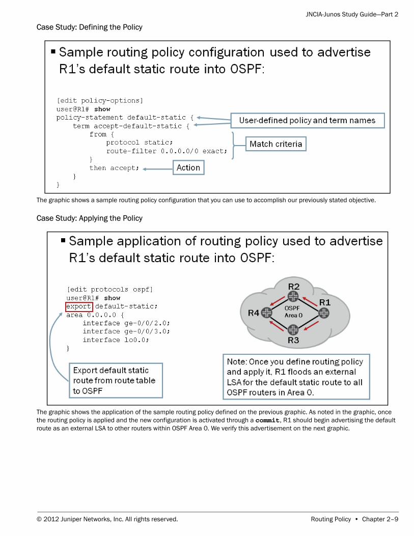
Case Study: Defining the Policy
The graphic shows a sample routing policy configuration that you can use to accomplish our previously stated objective.
Case Study: Applying the Policy
The graphic shows the application of the sample routing policy defined on the previous graphic. As noted in the graphic, once the routing policy is applied and the new configuration is activated through a commit, R1 should begin advertising the default route as an external LSA to other routers within OSPF Area 0. We verify this advertisement on the next graphic.
© 2012 Juniper Networks, Inc. All rights reserved. Routing Policy • Chapter 2–9
JNCIA-Junos Study Guide—Part 2
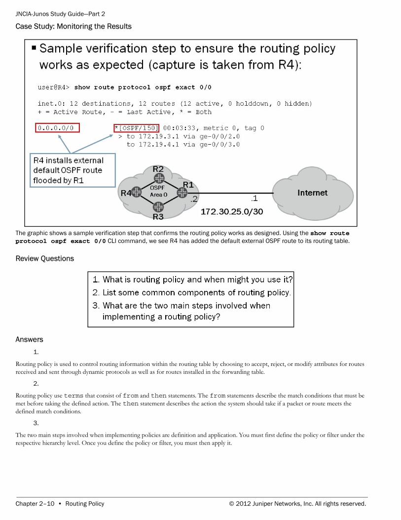
Case Study: Monitoring the Results
The graphic shows a sample verification step that confirms the routing policy works as designed. Using the show route protocol ospf exact 0/0 CLI command, we see R4 has added the default external OSPF route to its routing table.
Review Questions
Answers 1.
Routing policy is used to control routing information within the routing table by choosing to accept, reject, or modify attributes for routes received and sent through dynamic protocols as well as for routes installed in the forwarding table.
2.
Routing policy use terms that consist of from and then statements. The from statements describe the match conditions that must be met before taking the defined action. The then statement describes the action the system should take if a packet or route meets the defined match conditions.
3.
The two main steps involved when implementing policies are definition and application. You must first define the policy or filter under the respective hierarchy level. Once you define the policy or filter, you must then apply it.
Chapter 2–10 • Routing Policy © 2012 Juniper Networks, Inc. All rights reserved.
JNCIA-Junos Study Guide—Part 2
Chapter 3: Firewall Filters
This Chapter Discusses:• The framework of firewall filters;
• Firewall filter evaluation;
• Typical usage scenarios for firewall filters;
• Configuration and application of firewall filters; and
• Unicast reverse path forwarding (RPF).
Firewall Filters Firewall filters are often referred to as access control lists (ACLs) by other vendors. The Junos firewall filters are stateless in nature, and the software primarily uses them to control traffic passing through a Junos device.
Stateless firewall filters examine each packet individually. Thus, unlike a stateful firewall that tracks connections and allows you to specify an action to take on all packets within a flow, a stateless firewall filter has no concept of connections. The stateless nature of these filters can impact the way you write your firewall filters. Because the system does not keep state information on connections, you must explicitly allow traffic in both directions for each connection that you want to permit. By contrast, stateful firewall filters only require you to permit the initial connection and then automatically permit bidirectional communications for this connection.
You can use firewall filters to restrict certain types of traffic from passing into and out of your network. You can also use firewall filters to perform monitoring tasks that help you formulate an effective security strategy for your environment.
© 2012 Juniper Networks, Inc. All rights reserved. Firewall Filters • Chapter 3–1
JNCIA-Junos Study Guide—Part 2
Building Blocks of Firewall Filters
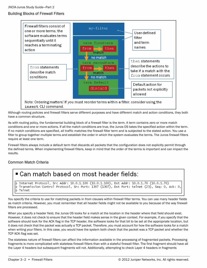
Although routing policies and firewall filters serve different purposes and have different match and action conditions, they both have a common structure.
As with routing policy, the fundamental building block of a firewall filter is the term. A term contains zero or more match conditions and one or more actions. If all the match conditions are true, the Junos OS takes the specified action within the term. If no match conditions are specified, all traffic matches the firewall filter term and is subjected to the stated action. You use a filter to group together multiple terms and establish the order in which the system evaluates the terms. The Junos firewall filters require at least one term.
Firewall filters always include a default term that discards all packets that the configuration does not explicitly permit through the defined terms. When implementing firewall filters, keep in mind that the order of the terms is important and can impact the results.
Common Match Criteria
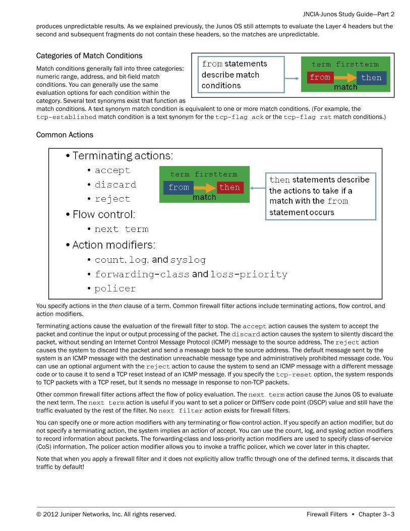
You specify the criteria to use for matching packets in from clauses within firewall filter terms. You can use many header fields as match criteria. However, you must remember that all header fields might not be available to you because of the way firewall filters are processed.
When you specify a header field, the Junos OS looks for a match at the location in the header where that field should exist. However, it does not check to ensure that the header field makes sense in the given context. For example, if you specify that the software should look for the ACK flag in the TCP header, the software looks for that bit to be set at the appropriate location, but it does not check that the packet was actually a TCP packet. Therefore, you must account for how the software looks for a match when writing your filters. In this case, you would have the system both check that the packet was a TCP packet and whether the TCP ACK flag was set.
The stateless nature of firewall filters can affect the information available in the processing of fragmented packets. Processing fragments is more complicated with stateless firewall filters than with a stateful firewall filter. The first fragment should have all the Layer 4 headers but subsequent fragments will not. Additionally, attempting to check Layer 4 headers in fragments
Chapter 3–2 • Firewall Filters © 2012 Juniper Networks, Inc. All rights reserved.
JNCIA-Junos Study Guide—Part 2
produces unpredictable results. As we explained previously, the Junos OS still attempts to evaluate the Layer 4 headers but the second and subsequent fragments do not contain these headers, so the matches are unpredictable.
Categories of Match ConditionsMatch conditions generally fall into three categories: numeric range, address, and bit-field match conditions. You can generally use the same evaluation options for each condition within the category. Several text synonyms exist that function as match conditions. A text synonym match condition is equivalent to one or more match conditions. (For example, the tcp-established match condition is a text synonym for the tcp-flag ack or the tcp-flag rst match conditions.)
Common Actions
You specify actions in the then clause of a term. Common firewall filter actions include terminating actions, flow control, and action modifiers.
Terminating actions cause the evaluation of the firewall filter to stop. The accept action causes the system to accept the packet and continue the input or output processing of the packet. The discard action causes the system to silently discard the packet, without sending an Internet Control Message Protocol (ICMP) message to the source address. The reject action causes the system to discard the packet and send a message back to the source address. The default message sent by the system is an ICMP message with the destination unreachable message type and administratively prohibited message code. You can use an optional argument with the reject action to cause the system to send an ICMP message with a different message code or to cause it to send a TCP reset instead of an ICMP message. If you specify the tcp-reset option, the system responds to TCP packets with a TCP reset, but it sends no message in response to non-TCP packets.
Other common firewall filter actions affect the flow of policy evaluation. The next term action cause the Junos OS to evaluate the next term. The next term action is useful if you want to set a policer or DiffServ code point (DSCP) value and still have the traffic evaluated by the rest of the filter. No next filter action exists for firewall filters.
You can specify one or more action modifiers with any terminating or flow-control action. If you specify an action modifier, but do not specify a terminating action, the system implies an action of accept. You can use the count, log, and syslog action modifiers to record information about packets. The forwarding-class and loss-priority action modifiers are used to specify class-of-service (CoS) information. The policer action modifier allows you to invoke a traffic policer, which we cover later in this chapter.
Note that when you apply a firewall filter and it does not explicitly allow traffic through one of the defined terms, it discards that traffic by default!
© 2012 Juniper Networks, Inc. All rights reserved. Firewall Filters • Chapter 3–3
JNCIA-Junos Study Guide—Part 2
Defining a Firewall Filter
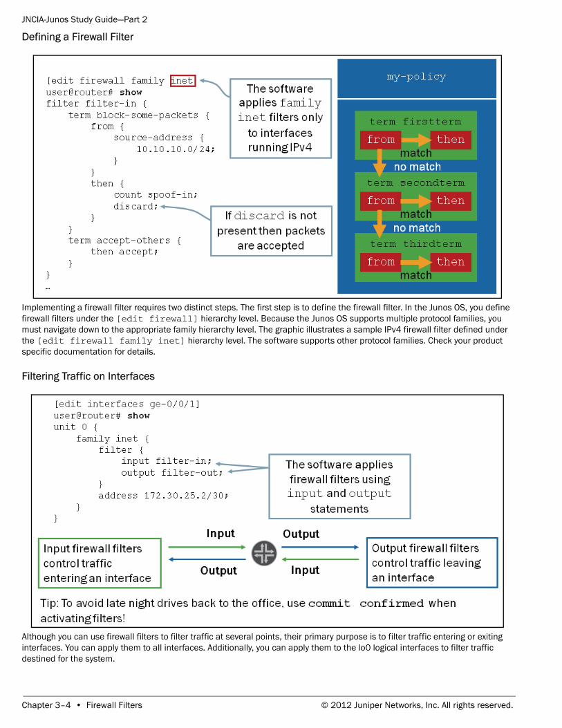
Implementing a firewall filter requires two distinct steps. The first step is to define the firewall filter. In the Junos OS, you define firewall filters under the [edit firewall] hierarchy level. Because the Junos OS supports multiple protocol families, you must navigate down to the appropriate family hierarchy level. The graphic illustrates a sample IPv4 firewall filter defined under the [edit firewall family inet] hierarchy level. The software supports other protocol families. Check your product specific documentation for details.
Filtering Traffic on Interfaces
Although you can use firewall filters to filter traffic at several points, their primary purpose is to filter traffic entering or exiting interfaces. You can apply them to all interfaces. Additionally, you can apply them to the lo0 logical interfaces to filter traffic destined for the system.
Chapter 3–4 • Firewall Filters © 2012 Juniper Networks, Inc. All rights reserved.
JNCIA-Junos Study Guide—Part 2
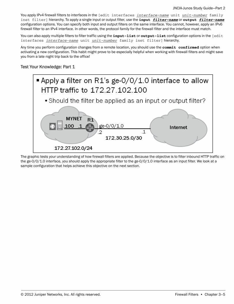
You apply IPv4 firewall filters to interfaces in the [edit interfaces interface-name unit unit-number family inet filter] hierarchy. To apply a single input or output filter, use the input filter-name or output filter-name configuration options. You can specify both input and output filters on the same interface. You cannot, however, apply an IPv6 firewall filter to an IPv4 interface. In other words, the protocol family for the firewall filter and the interface must match.
You can also apply multiple filters to filter traffic using the input-list or output-list configuration options in the [edit interfaces interface-name unit unit-number family inet filter] hierarchy.
Any time you perform configuration changes from a remote location, you should use the commit confirmed option when activating a new configuration. This habit might prove to be especially helpful when working with firewall filters and might save you from a late night trip back to the office!
Test Your Knowledge: Part 1
The graphic tests your understanding of how firewall filters are applied. Because the objective is to filter inbound HTTP traffic on the ge-0/0/1.0 interface, you should apply the appropriate filter to the ge-0/0/1.0 interface as an input filter. We look at a sample configuration that helps achieve this objective on the next section.
© 2012 Juniper Networks, Inc. All rights reserved. Firewall Filters • Chapter 3–5
JNCIA-Junos Study Guide—Part 2
Test Your Knowledge: Part 2
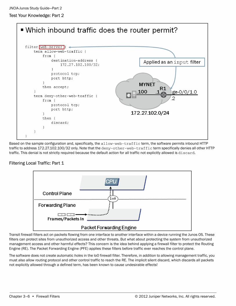
Based on the sample configuration and, specifically, the allow-web-traffic term, the software permits inbound HTTP traffic to address 172.27.102.100/32 only. Note that the deny-other-web-traffic term specifically denies all other HTTP traffic. This denial is not strictly required because the default action for all traffic not explicitly allowed is discard.
Filtering Local Traffic: Part 1
Transit firewall filters act on packets flowing from one interface to another interface within a device running the Junos OS. These filters can protect sites from unauthorized access and other threats. But what about protecting the system from unauthorized management access and other harmful effects? This concern is the idea behind applying a firewall filter to protect the Routing Engine (RE). The Packet Forwarding Engine (PFE) applies these filters before traffic ever reaches the control plane.
The software does not create automatic holes in the lo0 firewall filter. Therefore, in addition to allowing management traffic, you must also allow routing protocol and other control traffic to reach the RE. The implicit silent discard, which discards all packets not explicitly allowed through a defined term, has been known to cause undesirable effects!
Chapter 3–6 • Firewall Filters © 2012 Juniper Networks, Inc. All rights reserved.
JNCIA-Junos Study Guide—Part 2
Filtering Local Traffic: Part 2
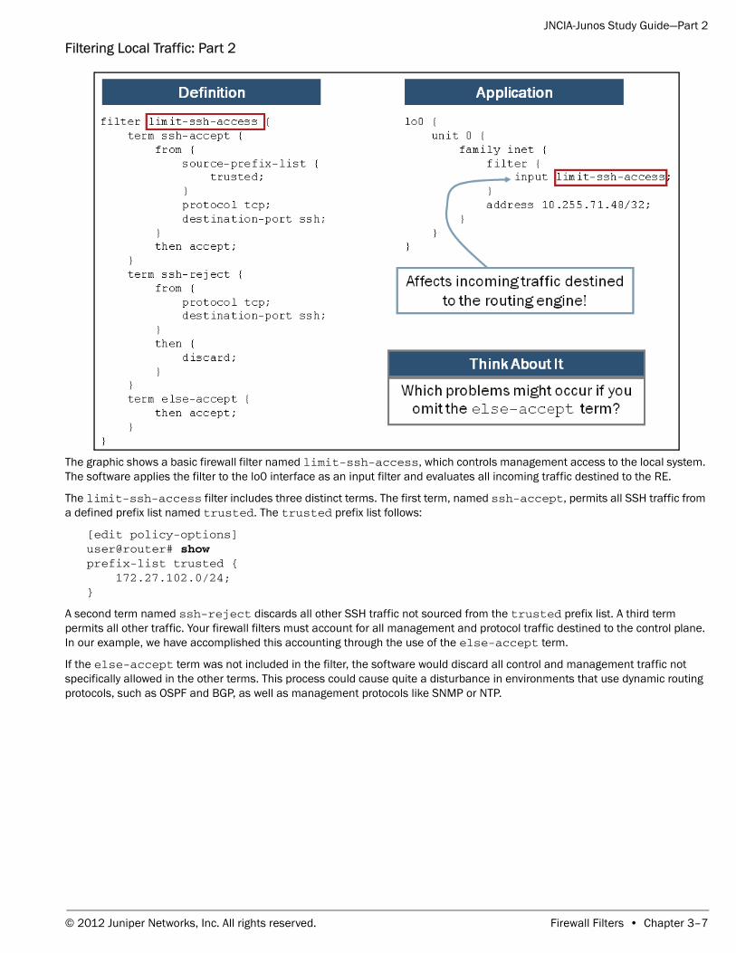
The graphic shows a basic firewall filter named limit-ssh-access, which controls management access to the local system. The software applies the filter to the lo0 interface as an input filter and evaluates all incoming traffic destined to the RE.
The limit-ssh-access filter includes three distinct terms. The first term, named ssh-accept, permits all SSH traffic from a defined prefix list named trusted. The trusted prefix list follows:
[edit policy-options]user@router# show prefix-list trusted { 172.27.102.0/24;}
A second term named ssh-reject discards all other SSH traffic not sourced from the trusted prefix list. A third term permits all other traffic. Your firewall filters must account for all management and protocol traffic destined to the control plane. In our example, we have accomplished this accounting through the use of the else-accept term.
If the else-accept term was not included in the filter, the software would discard all control and management traffic not specifically allowed in the other terms. This process could cause quite a disturbance in environments that use dynamic routing protocols, such as OSPF and BGP, as well as management protocols like SNMP or NTP.
© 2012 Juniper Networks, Inc. All rights reserved. Firewall Filters • Chapter 3–7
JNCIA-Junos Study Guide—Part 2
Policing
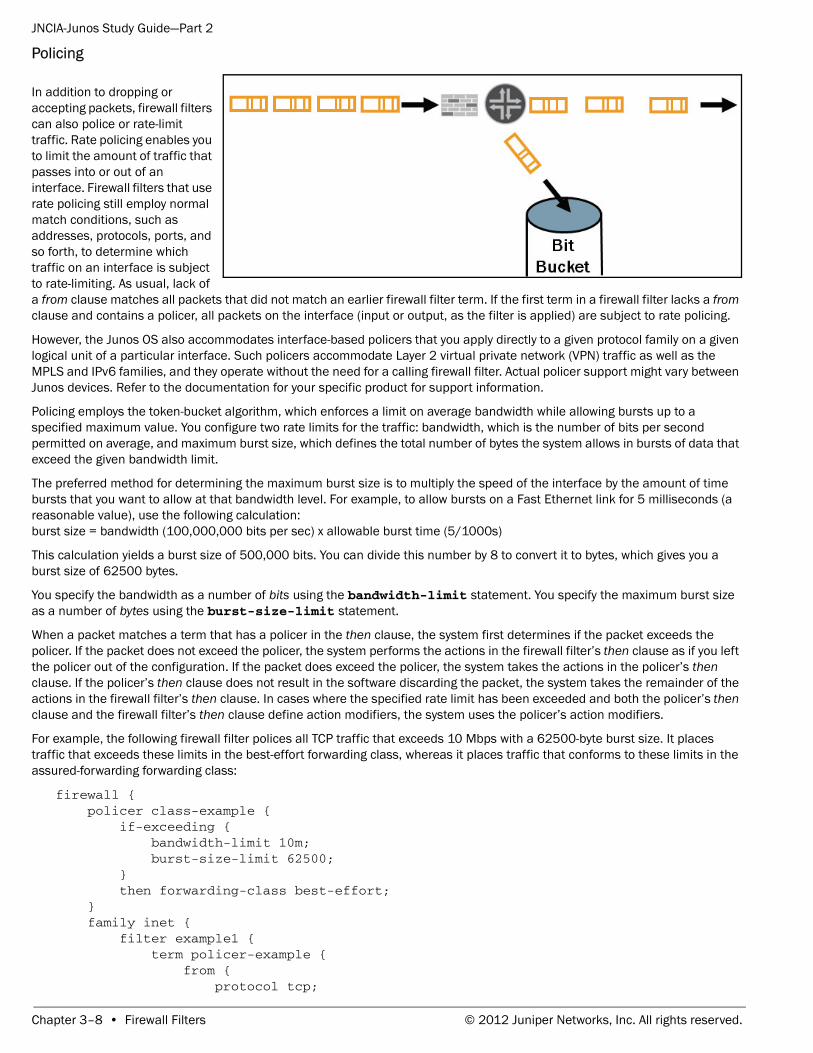
In addition to dropping or accepting packets, firewall filters can also police or rate-limit traffic. Rate policing enables you to limit the amount of traffic that passes into or out of an interface. Firewall filters that use rate policing still employ normal match conditions, such as addresses, protocols, ports, and so forth, to determine which traffic on an interface is subject to rate-limiting. As usual, lack of a from clause matches all packets that did not match an earlier firewall filter term. If the first term in a firewall filter lacks a from clause and contains a policer, all packets on the interface (input or output, as the filter is applied) are subject to rate policing.
However, the Junos OS also accommodates interface-based policers that you apply directly to a given protocol family on a given logical unit of a particular interface. Such policers accommodate Layer 2 virtual private network (VPN) traffic as well as the MPLS and IPv6 families, and they operate without the need for a calling firewall filter. Actual policer support might vary between Junos devices. Refer to the documentation for your specific product for support information.
Policing employs the token-bucket algorithm, which enforces a limit on average bandwidth while allowing bursts up to a specified maximum value. You configure two rate limits for the traffic: bandwidth, which is the number of bits per second permitted on average, and maximum burst size, which defines the total number of bytes the system allows in bursts of data that exceed the given bandwidth limit.
The preferred method for determining the maximum burst size is to multiply the speed of the interface by the amount of time bursts that you want to allow at that bandwidth level. For example, to allow bursts on a Fast Ethernet link for 5 milliseconds (a reasonable value), use the following calculation: burst size = bandwidth (100,000,000 bits per sec) x allowable burst time (5/1000s)
This calculation yields a burst size of 500,000 bits. You can divide this number by 8 to convert it to bytes, which gives you a burst size of 62500 bytes.
You specify the bandwidth as a number of bits using the bandwidth-limit statement. You specify the maximum burst size as a number of bytes using the burst-size-limit statement.
When a packet matches a term that has a policer in the then clause, the system first determines if the packet exceeds the policer. If the packet does not exceed the policer, the system performs the actions in the firewall filter’s then clause as if you left the policer out of the configuration. If the packet does exceed the policer, the system takes the actions in the policer’s then clause. If the policer’s then clause does not result in the software discarding the packet, the system takes the remainder of the actions in the firewall filter’s then clause. In cases where the specified rate limit has been exceeded and both the policer’s then clause and the firewall filter’s then clause define action modifiers, the system uses the policer’s action modifiers.
For example, the following firewall filter polices all TCP traffic that exceeds 10 Mbps with a 62500-byte burst size. It places traffic that exceeds these limits in the best-effort forwarding class, whereas it places traffic that conforms to these limits in the assured-forwarding forwarding class:
firewall { policer class-example { if-exceeding { bandwidth-limit 10m; burst-size-limit 62500; } then forwarding-class best-effort; } family inet { filter example1 { term policer-example { from { protocol tcp;
Chapter 3–8 • Firewall Filters © 2012 Juniper Networks, Inc. All rights reserved.
JNCIA-Junos Study Guide—Part 2
} then { policer class-example; forwarding-class assured-forwarding; accept; } } } }}
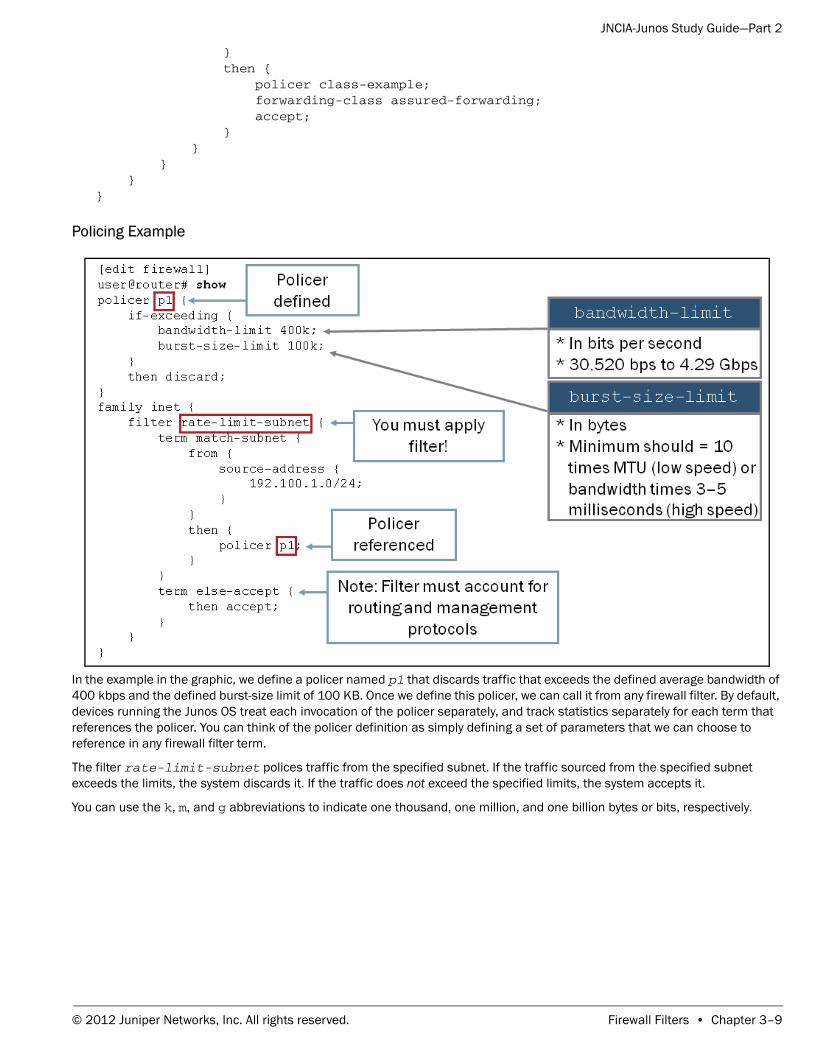
Policing Example
In the example in the graphic, we define a policer named p1 that discards traffic that exceeds the defined average bandwidth of 400 kbps and the defined burst-size limit of 100 KB. Once we define this policer, we can call it from any firewall filter. By default, devices running the Junos OS treat each invocation of the policer separately, and track statistics separately for each term that references the policer. You can think of the policer definition as simply defining a set of parameters that we can choose to reference in any firewall filter term.
The filter rate-limit-subnet polices traffic from the specified subnet. If the traffic sourced from the specified subnet exceeds the limits, the system discards it. If the traffic does not exceed the specified limits, the system accepts it.
You can use the k, m, and g abbreviations to indicate one thousand, one million, and one billion bytes or bits, respectively.
© 2012 Juniper Networks, Inc. All rights reserved. Firewall Filters • Chapter 3–9
JNCIA-Junos Study Guide—Part 2
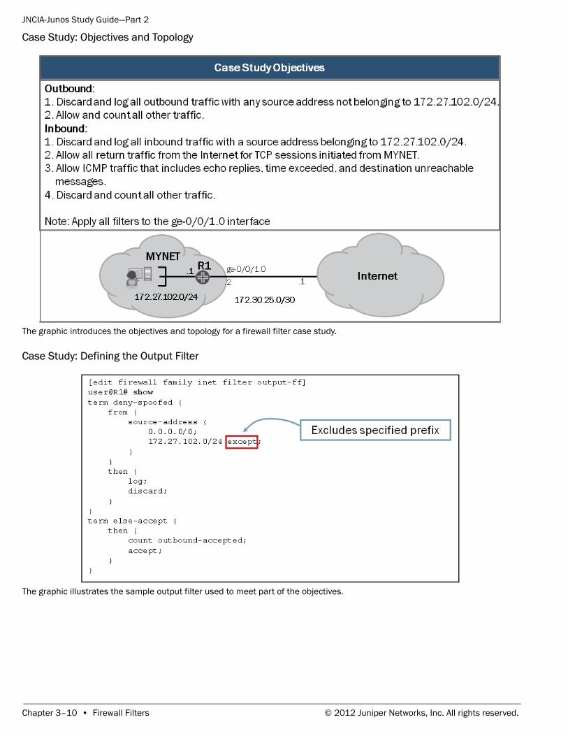
Case Study: Objectives and Topology
The graphic introduces the objectives and topology for a firewall filter case study.
Case Study: Defining the Output Filter
The graphic illustrates the sample output filter used to meet part of the objectives.
Chapter 3–10 • Firewall Filters © 2012 Juniper Networks, Inc. All rights reserved.
JNCIA-Junos Study Guide—Part 2
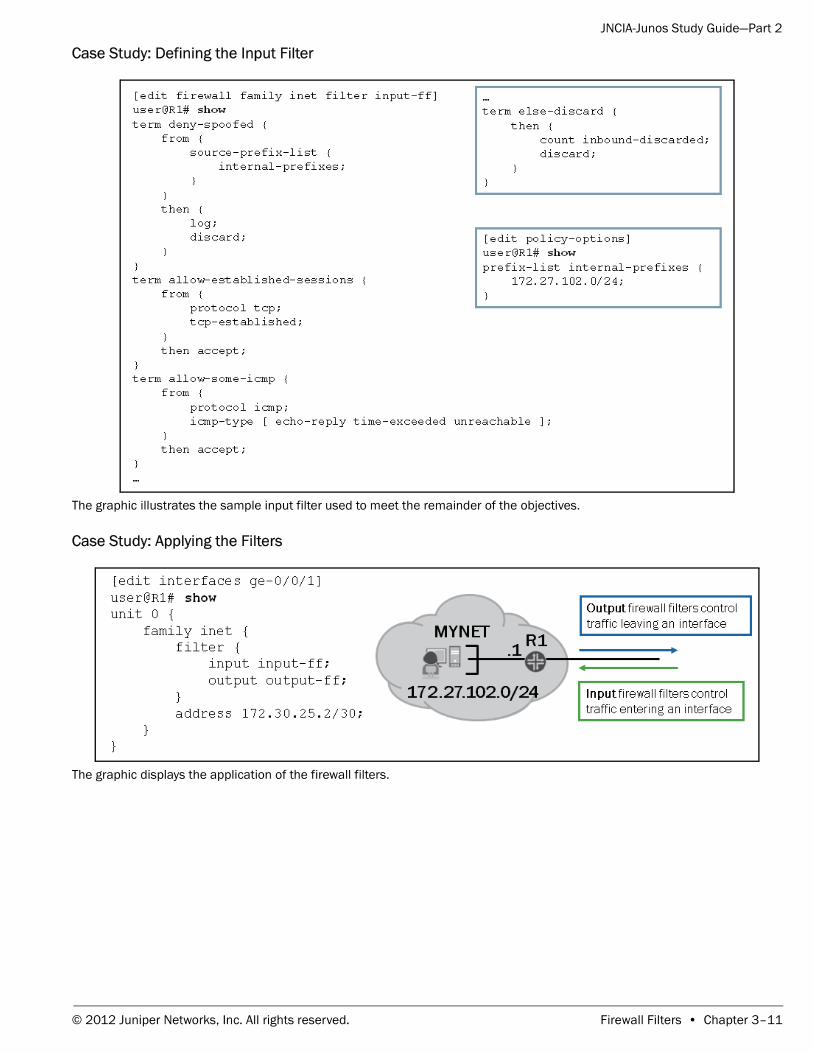
Case Study: Defining the Input Filter
The graphic illustrates the sample input filter used to meet the remainder of the objectives.
Case Study: Applying the Filters
The graphic displays the application of the firewall filters.
© 2012 Juniper Networks, Inc. All rights reserved. Firewall Filters • Chapter 3–11
JNCIA-Junos Study Guide—Part 2
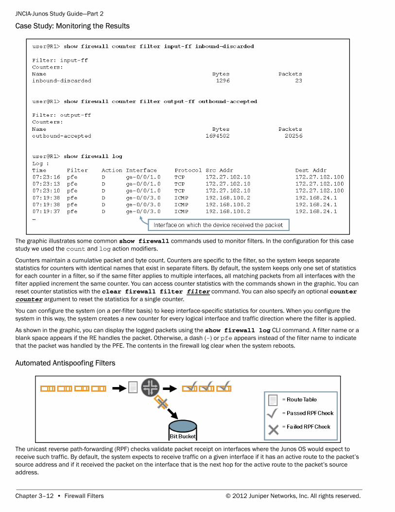
Case Study: Monitoring the Results
The graphic illustrates some common show firewall commands used to monitor filters. In the configuration for this case study we used the count and log action modifiers.
Counters maintain a cumulative packet and byte count. Counters are specific to the filter, so the system keeps separate statistics for counters with identical names that exist in separate filters. By default, the system keeps only one set of statistics for each counter in a filter, so if the same filter applies to multiple interfaces, all matching packets from all interfaces with the filter applied increment the same counter. You can access counter statistics with the commands shown in the graphic. You can reset counter statistics with the clear firewall filter filter command. You can also specify an optional counter counter argument to reset the statistics for a single counter.
You can configure the system (on a per-filter basis) to keep interface-specific statistics for counters. When you configure the system in this way, the system creates a new counter for every logical interface and traffic direction where the filter is applied.
As shown in the graphic, you can display the logged packets using the show firewall log CLI command. A filter name or a blank space appears if the RE handles the packet. Otherwise, a dash (-) or pfe appears instead of the filter name to indicate that the packet was handled by the PFE. The contents in the firewall log clear when the system reboots.
Automated Antispoofing Filters
The unicast reverse path-forwarding (RPF) checks validate packet receipt on interfaces where the Junos OS would expect to receive such traffic. By default, the system expects to receive traffic on a given interface if it has an active route to the packet’s source address and if it received the packet on the interface that is the next hop for the active route to the packet’s source address.
Chapter 3–12 • Firewall Filters © 2012 Juniper Networks, Inc. All rights reserved.
JNCIA-Junos Study Guide—Part 2
For example, if a device running the Junos OS receives a packet with a source address of 10.10.10.10 on interface ge-0/0/1.0 and you configured the device to perform the unicast RPF check on that interface, it examines its routing table for the best route to 10.10.10.10. If this route lookup returns a route for 10.10.10.0/24 with a next hop of ge-0/0/1.0, the packet passes the unicast RPF check and is accepted. You can combine both unicast RPF and firewall filters on the same interface.
The Junos OS accomplishes unicast RPF checks by downloading additional information to the PFE. Therefore, activating this feature increases PFE memory usage.
Strict Versus LooseBy default, devices running the Junos OS use the strict mode RPF check. You can instead configure it to use the loose mode RPF check, which checks only to ensure a valid route to the source address exists in the routing table. However, in networks with a default route, a valid route to every IP address always exists; so, using a loose mode check does not make sense in this environment. In general, using the default strict mode provides the best results.
Active Versus Feasible Paths
By default, when a Junos device performs its RPF check, it considers only the active routes to a given destination. In networks where perfectly symmetric routing exists, the default behavior of considering only active routes should work. However, in cases where the possibility of asymmetric routing (different forward and reverse paths) exists, this design can cause legitimate traffic to be dropped. To alleviate this issue, you can require that the system consider all feasible routes to a destination when it performs the RPF check. In this mode, the system considers all routes it receives to a given prefix, even if they are not the active route to the destination. In networks where the possibility of asymmetric routing exists, you should activate this option.
You do not need to implement RPF checking on all devices within your network. Typically, you configure only the edge device to perform RPF checking because all inbound and outbound spoofing passes through that device. In the sample network shown in the graphic, R1 should be configured to perform RPF checks on all three interfaces.
Unicast RPF configuration options vary between Junos devices. Check your product specific documentation for detailed support information.
© 2012 Juniper Networks, Inc. All rights reserved. Firewall Filters • Chapter 3–13
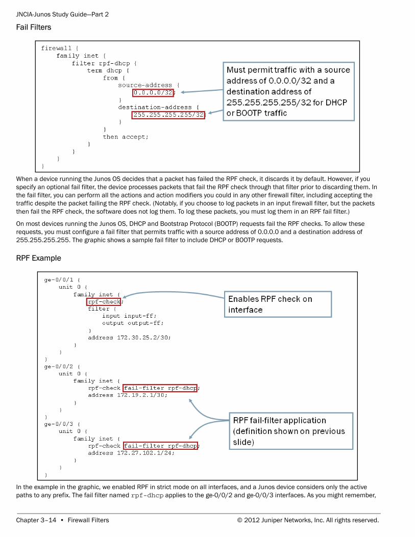
JNCIA-Junos Study Guide—Part 2
Fail Filters
When a device running the Junos OS decides that a packet has failed the RPF check, it discards it by default. However, if you specify an optional fail filter, the device processes packets that fail the RPF check through that filter prior to discarding them. In the fail filter, you can perform all the actions and action modifiers you could in any other firewall filter, including accepting the traffic despite the packet failing the RPF check. (Notably, if you choose to log packets in an input firewall filter, but the packets then fail the RPF check, the software does not log them. To log these packets, you must log them in an RPF fail filter.)
On most devices running the Junos OS, DHCP and Bootstrap Protocol (BOOTP) requests fail the RPF checks. To allow these requests, you must configure a fail filter that permits traffic with a source address of 0.0.0.0 and a destination address of 255.255.255.255. The graphic shows a sample fail filter to include DHCP or BOOTP requests.
RPF Example
In the example in the graphic, we enabled RPF in strict mode on all interfaces, and a Junos device considers only the active paths to any prefix. The fail filter named rpf-dhcp applies to the ge-0/0/2 and ge-0/0/3 interfaces. As you might remember,
Chapter 3–14 • Firewall Filters © 2012 Juniper Networks, Inc. All rights reserved.
JNCIA-Junos Study Guide—Part 2
the configuration defines the rpf-dhcp fail-filter on the previous graphic and permits DHCP and BOOTP requests. Now that you enabled RPF on all interfaces, you do not need to include antispoofing terms within the firewall filters.
Review Questions
Answers1.
Some common firewall filter actions are accept, discard, reject, and next term. The accept action accepts the packet and continues the input or output processing of the packet. The discard action silently rejects the packet, in contrast to the reject action that drops the packet and sends an ICMP message to the source address. The next term action causes the Junos OS to evaluate the next term and is usually used when using a policer and still want the traffic to be evaluated by the rest of the filter.
2.
The default action for packets not explicitly permitted through a firewall filter is discard.
3.
Unicast RPF automates antispoofing on a device running the Junos OS.
.
© 2012 Juniper Networks, Inc. All rights reserved. Firewall Filters • Chapter 3–15
Recommended