
International Journal of Engineering Sciences & Research
Technology (A Peer Reviewed Online Journal)
Impact Factor: 5.164
IJESRT
Chief Editor Executive Editor
Dr. J.B. Helonde Mr. Somil Mayur Shah
Website: www.ijesrt.com Mail: [email protected] O
IJESRT: 9(2), February, 2020 ISSN: 2277-9655
I X
ISSN: 2277-9655
[Suman, et al., 9(2): February, 2020] Impact Factor: 5.164
IC™ Value: 3.00 CODEN: IJESS7
http: // www.ijesrt.com© International Journal of Engineering Sciences & Research Technology
[17]
IJESRT is licensed under a Creative Commons Attribution 4.0 International License.
IJESRT INTERNATIONAL JOURNAL OF ENGINEERING SCIENCES & RESEARCH
TECHNOLOGY
COMPARATIVE THERMODYNAMIC PERFORMANCE ANALYSIS OF A
CASCADE SYSTEM USING DIFFERENT REFRIGERANT COUPLES Sourav Suman, Sujeet Kumar Singh
1M.Tech Scholar, Department of Mechanical Engineering, PCST, Bhopal 2Prof., Department of Mechanical Engineering, PCST, Bhopal
DOI: 10.5281/zenodo.3653477
ABSTRACT In present study the comparison of thermodynamic analysis of cascade refrigeration system has been done with
refrigerant pairs such as CO2-HFE7000, CO2-R134a, CO2-R152a, CO2-R32, CO2-R1234yf, CO2-NH3, CO2-
Propane and CO2-Propylene. In these systems, performance of two stage cascade compression system using
above different refrigerant couples, have been studied and the effect of condenser temperature & evaporator
temperature, has been done. Thermodynamic analysis is carried out by developing computational model in
Engineering Equation solver (EES).
KEYWORDS: Cascade refrigeration system, low temperature circuit (LTC), high temperature circuit (HTC),
coefficient of performance (COP), global warming potential (GWP), ozone depletion potential (ODP)
1. INTRODUCTION Many industrial applications require low temperature refrigeration such as quick freezing biomedical
preservations, manufacturing of dry ice, liquefaction of petroleum vapors, pharmaceutical reactions etc. where
evaporating temperature requires between -40ºC to- 80ºC. Condensing temperature is governed by temperature
of cooling tower water which is about 35 ºC. Thus, system has to work for wide range of temperature. Single
stage vapor compression system is not feasible for such application and its performance decreases below -35 ºC.
Multistage or compound systems can be useful but no refrigerants available to work efficiently for high
temperature lift. Also, it will be difficult to balance the oil level in compressor because of large difference in
suction pressures of low stage and higher stage compressors. Cascade refrigeration system has two different
stages which permits appropriate selection refrigerants to maximise system performance. Synthetic refrigerants
prominently used in till now due to their excellent thermodynamic properties but owing to higher ODP (Ozone
Depletion Potential), GWP (Global worming Potential) they are contributor to ozone depletion and global
warming. Cascade refrigeration system is the combination of two single stage vapor compression system
together, condenser of LTC and evaporator of HTC is cascaded and forms the heat exchanger where evaporator
cascade absorbs the heat from the condenser cascade which further leads to better refrigeration effect.
Amongst the natural refrigerants, Lorentzen and Petterson [1] suggested the use of carbon dioxide (CO2) and
seems to be the most promising one especially as the natural refrigerant [1-6]. The key advantages of CO2
include the fact that is not explosive, non-toxic, easily available, environmental friendly and has excellent
thermo-physical properties. On the other hand, researches in Norway in 1993 showed that the refrigerant
leakages coming from the commercial sector were 30% of the annual total [7]. In this research, the use of a
cascade system using CO2 in the low temperature stage and NH3 in the high temperature stage turned out to be
an excellent alternative for cooling applications at very low temperatures [8-10]. Researches from Eggen and
Aflekt [11], Pearson and Cable [12] and Van Riessen [13] show practical examples of the use of a cascade
system of CO2/NH3 for cooling in supermarkets. Eggen and Aflekt [11] developed research based on a
prototype of a cooling system built in Norway. Pearson and Cable [12] showed data from a cooling system used
in a Scottish supermarket line, (ASDA), and Van Riessen [13] carried out technical energy and economic
research of a cooling system used in a Dutch supermarket. In the same way, different researches about the
performance of different cooling systems involving CO2 have been carried out together with its reuse as a
refrigerant fluid. Lorentzen and Petterson [1] evaluated the possibility of the use of a heat exchanger in a CO2
transcritical system. Hwang et al. [6] showed experimental results and simulation research including expansors
and double stage cycles. Groll et al. [14] carried out a numerical analysis of a double stage cycle changing the
ISSN: 2277-9655
[Suman, et al., 9(2): February, 2020] Impact Factor: 5.164
IC™ Value: 3.00 CODEN: IJESS7
http: // www.ijesrt.com© International Journal of Engineering Sciences & Research Technology
[18]
IJESRT is licensed under a Creative Commons Attribution 4.0 International License.
compression ratio of each compression stage. It is well-known that cascade refrigeration system (CRS) is
usually adopted to meet the low-temperature cooling requirement in many commercial and industrial
applications where single-stage or multistage systems are insufficient. There are two cycles in a cascade
refrigeration system: the high-temperature cycle (HTC) is used to absorbed the energy released by the low-
temperature cycle (LTC) during the condensation process [1]. In this way, CRS can satisfy the low-temperature
cooling requirement range from -30°C to -55°C [2]. Regarding energy shortage problems, much attention has
been devoted to the optimization of CRS performance. One of the research topics is the selection of refrigerant
couples [3]. A suitable refrigerant couple is able to provide a large temperature lift while improving system
performance [2]. The HTC of a CRS can normally be charged as an intermediate-temperature refrigerant with a
normal boiling point ranging from 0 °C to -60°C, such as R22 [4], R404A [5], R290, NH3(R717), propylene
(R1270), R12, R134a, and R410a, whereas the normal boiling points of low-temperature refrigerants such as
R23, carbon dioxide (R744) and N2O are usually lower than -70°C. However, there is no definite temperature
boundary between,
2. SYSTEM MODELLING To aid in analysis of engineering problem it is necessary to realize the Physical model in a mathematical model.
To do this, we first write state point equations of thermodynamic properties and then develop a polynomial for
thermodynamic properties with the help of software or, directly taken from the reference. Therefore this chapter
involves the description of physical model, mass, and energy balance, assumptions, state point equations and
thermodynamic properties. To show the superiority of cascade system for low temperature application or to
justify the utility of cascade system for low temperature cooling (below -40° c), it becomes necessary to analyse
them separately .Thus this chapter deals with the mathematical modelling of two sections. The schematic
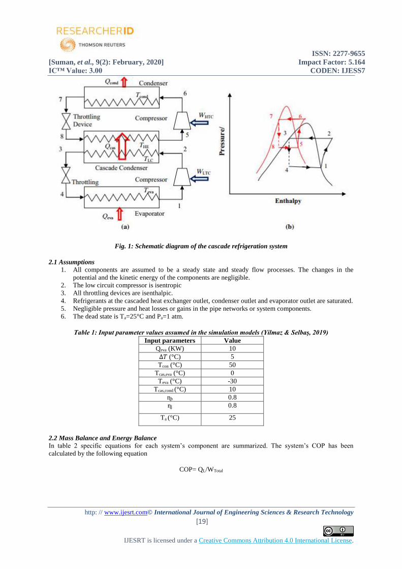
diagram of a typical CRS and the corresponding p–h plot are shown in Fig. 1 a, b, respectively. In CRS, two
single-stage vapour compression refrigeration cycles are connected with each other in series through a cascade
heat exchanger. This cascade heat exchanger serves as condenser for the low-temperature circuit (LTC) and as
evaporator for the high-temperature circuit (HTC). In the cascade heat exchanger, the LTC refrigerant rejects the
heat which is absorbed by HTC refrigerant. In the evaporator, Qeva amount of heat is absorbed by the LTC
refrigerant at evaporator temperature of Teva and gets evaporated. The vapour refrigerant then enters the LTC
compressor (state 1), where WLTC amount of work is supplied to raise its temperature and pressure (state 2). It
is then sent to the cascade heat exchanger where LTC refrigerant rejects Qcas amount of heat at LTC condenser
temperature, TLC which is absorbed by the HTC refrigerant at HTC evaporator temperature, THE. This causes
condensation (state 3) of the LTC refrigerant and evaporation (state 5) of the HTC refrigerant. The condensed
LTC refrigerant then enters the LTC throttle device and expanded to the evaporator pressure (state 4) and enters
the evaporator. The vapourized HTC refrigerant, coming out from the cascade heat exchanger, enters the HTC
compressor. WHTC amount of work is consumed by the HTC compressor to compress the refrigerant to the
condenser pressure, and this compressed and superheated refrigerant enters the condenser at state 6. The
refrigerant vapour is first desuper heated and then condensed to saturated liquid (state 7) at condenser
temperature of Tcond by rejecting Qcond amount of heat. The condensed HTC refrigerant is then passed
through the HTC throttle device and expands to the HTC evaporator pressure at state 8. The evaporator
temperature, condenser temperature, LTC condenser temperature and the temperature difference in the cascade
heat exchanger are the four most important parameters which have great influence on the performance of
system.
ISSN: 2277-9655
[Suman, et al., 9(2): February, 2020] Impact Factor: 5.164
IC™ Value: 3.00 CODEN: IJESS7
http: // www.ijesrt.com© International Journal of Engineering Sciences & Research Technology
[19]
IJESRT is licensed under a Creative Commons Attribution 4.0 International License.
Fig. 1: Schematic diagram of the cascade refrigeration system
2.1 Assumptions 1. All components are assumed to be a steady state and steady flow processes. The changes in the
potential and the kinetic energy of the components are negligible.
2. The low circuit compressor is isentropic
3. All throttling devices are isenthalpic.
4. Refrigerants at the cascaded heat exchanger outlet, condenser outlet and evaporator outlet are saturated.
5. Negligible pressure and heat losses or gains in the pipe networks or system components.
6. The dead state is Ta=25°C and Pa=1 atm.
Table 1: Input parameter values assumed in the simulation models (Yilmaz & Selbaş, 2019)
Input parameters Value
Qeva (KW) 10
∆𝑇 (°C) 5
Tcon (°C) 50
Tcas,eva (°C) 0
Teva (°C) -30
Tcas,cond (°C) 10
ɳh 0.8
ɳl 0.8
Ta (°C) 25
2.2 Mass Balance and Energy Balance
In table 2 specific equations for each system’s component are summarized. The system’s COP has been
calculated by the following equation
COP= QL/WTotal
ISSN: 2277-9655
[Suman, et al., 9(2): February, 2020] Impact Factor: 5.164
IC™ Value: 3.00 CODEN: IJESS7
http: // www.ijesrt.com© International Journal of Engineering Sciences & Research Technology
[20]
IJESRT is licensed under a Creative Commons Attribution 4.0 International License.
Table 2: Energy and Mass Balance for R22-R404a Cascade System
Component Mass Energy
HTC-Compressor
LTC-Compressor
HTC- Exp. Device
LTC- Exp. Device
Evaporator
Condenser
Cascade heat exchanger
m7=m8
m6=m5
m5=m6
m4=m1
m6=m7
m4=m3
m1=m2,m5=m8
Wcomp = m1.(h8-h7)/ɳl
Wcomp= m2.(h3-h2) /ɳh
h5=h6
h4=h1
Qevap = m1(h7-h6)
Qcond = m5(h4-h3)
m1.(h1-h2)=m2.(h5-h8)
3. THERMODYNAMIC ANALYSIS The thermodynamic analysis of CO2-HFE7000, CO2-R134a, CO2-R152a, CO2-R32, CO2-R1234yf, CO2-
365mfc, CO2-NH3, CO2-Propane and CO2-Propylene based cascade refrigeration system performed based on
the following assumptions.
1. Compression process is adiabatic with an isentropic efficiency of 0.8 in both HTC and LTC;
2. The expansion process is isenthalpic;
3. Negligible heat interaction in the cascade heat exchanger with surrounding;
4. Negligible changes in kinetic and potential energy;
5. The system is at steady state condition. All processes are steady flow processes.
6. Temperature difference in the cascade heat exchanger is 5°C.
The thermo-physical properties of CO2-HFE7000, CO2-R134a, CO2-R152a, CO2-R32, CO2-R1234yf, CO2-
365mfc, CO2-NH3, CO2-Propane and CO2-Propylene were specified in this work were calculating using a
software package called engineering equation solver (EES). A major feature of EES is the high accuracy
thermodynamic and transport property database that is provided for hundreds of substances in a manner that
allows it to be used with the equation solving capability. The cycle is modelled by applying mass balance and
energy balance equation for each individual process of the cycle. The equations for the different components of
the cascade refrigeration system are given in the previous chapter.
4. MATHEMATICAL FORMULATION
Mass balance
∑ 𝑚 =
𝑖𝑛
∑ ��
𝑜𝑢𝑡
Energy balance:
��- ��=∑ 𝑚ℎ𝑜𝑢𝑡 -∑ 𝑚ℎ𝑖𝑛
Exergy balance:
𝑋𝐿𝑜𝑠𝑡 = ∑ (1 −
𝑇𝑜
𝑇𝑖)𝑜𝑢𝑡 𝑄𝑖
- �� + ∑ 𝑚��𝑖𝑛 - ∑ ��𝑜𝑢𝑡 𝜑
ISSN: 2277-9655
[Suman, et al., 9(2): February, 2020] Impact Factor: 5.164
IC™ Value: 3.00 CODEN: IJESS7
http: // www.ijesrt.com© International Journal of Engineering Sciences & Research Technology
[21]
IJESRT is licensed under a Creative Commons Attribution 4.0 International License.
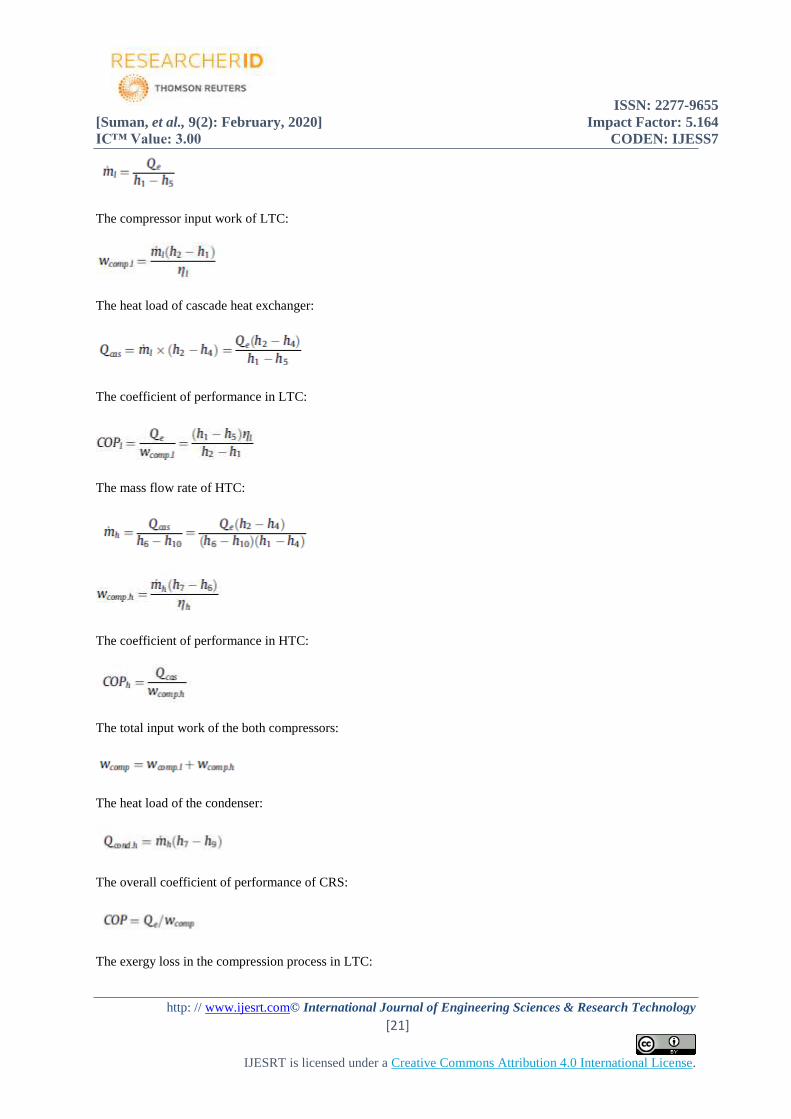
The compressor input work of LTC:
The heat load of cascade heat exchanger:
The coefficient of performance in LTC:
The mass flow rate of HTC:
The coefficient of performance in HTC:
The total input work of the both compressors:
The heat load of the condenser:
The overall coefficient of performance of CRS:
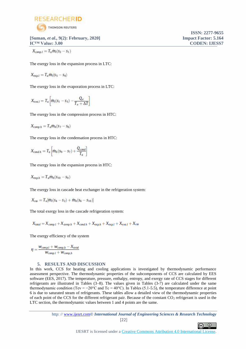
The exergy loss in the compression process in LTC:
ISSN: 2277-9655
[Suman, et al., 9(2): February, 2020] Impact Factor: 5.164
IC™ Value: 3.00 CODEN: IJESS7
http: // www.ijesrt.com© International Journal of Engineering Sciences & Research Technology
[22]
IJESRT is licensed under a Creative Commons Attribution 4.0 International License.
The exergy loss in the expansion process in LTC:
The exergy loss in the evaporation process in LTC:
The exergy loss in the compression process in HTC:
The exergy loss in the condensation process in HTC:
The exergy loss in the expansion process in HTC:
The exergy loss in cascade heat exchanger in the refrigeration system:
The total exergy loss in the cascade refrigeration system:
The exergy efficiency of the system
5. RESULTS AND DISCUSSION In this work, CCS for heating and cooling applications is investigated by thermodynamic performance
assessment perspective. The thermodynamic properties of the subcomponents of CCS are calculated by EES
software (EES, 2017). The temperature, pressure, enthalpy, entropy, and exergy rate of CCS stages for different
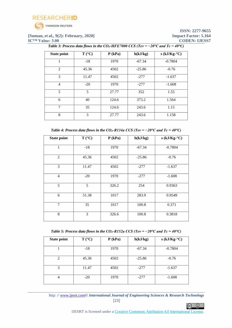
refrigerants are illustrated in Tables (3–8). The values given in Tables (3-7) are calculated under the same
thermodynamic condition (Tev = −20°C and Tc = 40°C). In Tables (5.1-5.5), the temperature difference at point
6 is due to saturated steam of refrigerants. These tables allow a detailed view of the thermodynamic properties
of each point of the CCS for the different refrigerant pair. Because of the constant CO2 refrigerant is used in the
LTC section, the thermodynamic values between 1 and 4 points are the same.
ISSN: 2277-9655
[Suman, et al., 9(2): February, 2020] Impact Factor: 5.164
IC™ Value: 3.00 CODEN: IJESS7
http: // www.ijesrt.com© International Journal of Engineering Sciences & Research Technology
[23]
IJESRT is licensed under a Creative Commons Attribution 4.0 International License.
Table 3: Process data flows in the CO2-HFE7000 CCS (Tev = −20°C and Tc = 40°C)
State point T (°C) P (kPa) h(kJ/kg) s (kJ/Kg-°C)
1 -18 1970 -67.34 -0.7804
2 45.36 4502 -25.86 -0.76
3 11.47 4502 -277 -1.637
4 -20 1970 -277 -1.608
5 5 27.77 352 1.55
6 40 124.6 373.2 1.564
7 35 124.6 243.6 1.15
8 3 27.77 243.6 1.158
Table 4: Process data flows in the CO2-R134a CCS (Tev = −20°C and Tc = 40°C)
State point T (°C) P (kPa) h(kJ/kg) s (kJ/Kg-°C)
1 -18 1970 -67.34 -0.7804
2 45.36 4502 -25.86 -0.76
3 11.47 4502 -277 -1.637
4 -20 1970 -277 -1.608
5 5 326.2 254 0.9363
6 51.38 1017 283.9 0.9549
7 35 1017 100.8 0.371
8 3 326.6 100.8 0.3818
Table 5: Process data flows in the CO2-R152a CCS (Tev = −20°C and Tc = 40°C)
State point T (°C) P (kPa) h(kJ/kg) s (kJ/Kg-°C)
1 -18 1970 -67.34 -0.7804
2 45.36 4502 -25.86 -0.76
3 11.47 4502 -277 -1.637
4 -20 1970 -277 -1.608
ISSN: 2277-9655
[Suman, et al., 9(2): February, 2020] Impact Factor: 5.164
IC™ Value: 3.00 CODEN: IJESS7
http: // www.ijesrt.com© International Journal of Engineering Sciences & Research Technology
[24]
IJESRT is licensed under a Creative Commons Attribution 4.0 International License.
5 5 294 510.9 2.126
6 59.48 910.3 558.2 2.155
7 35 910.3 262.3 1.212
8 3 294 262.3 1.226
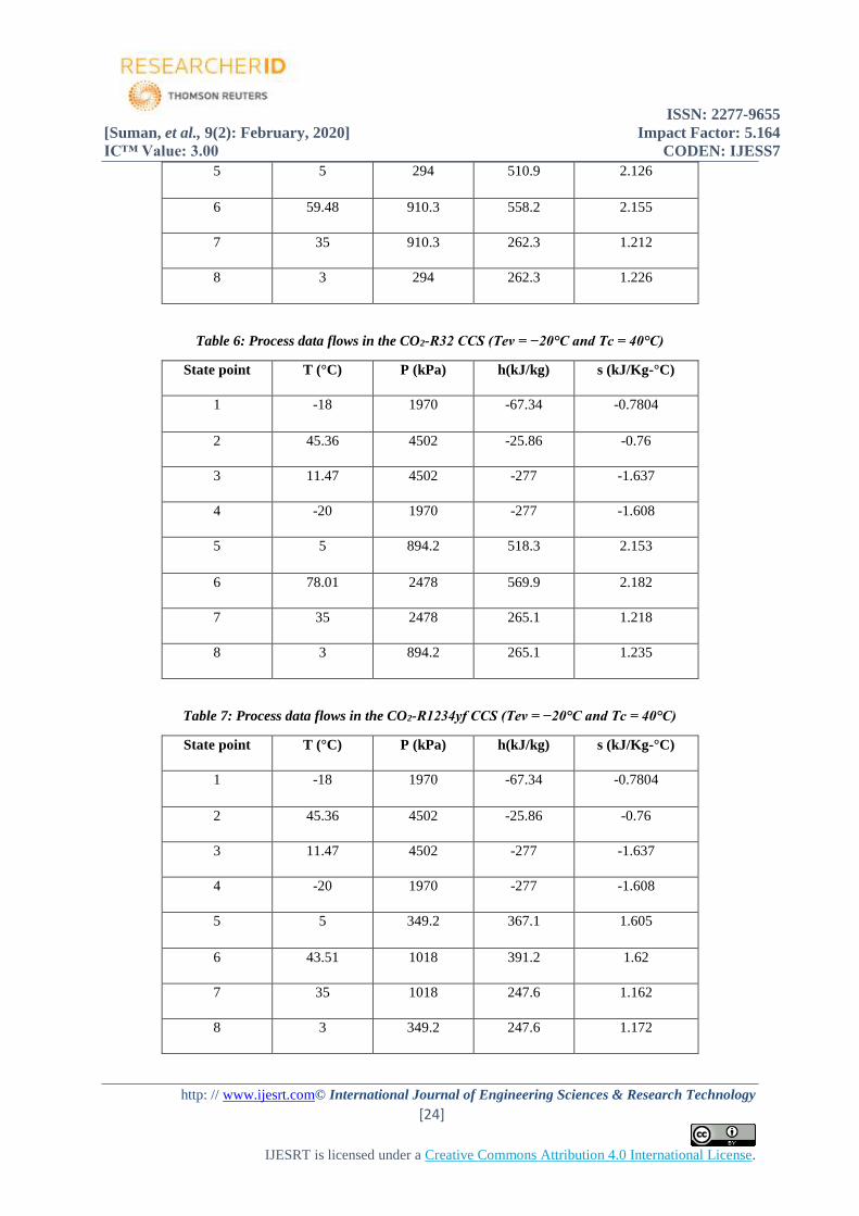
Table 6: Process data flows in the CO2-R32 CCS (Tev = −20°C and Tc = 40°C)
State point T (°C) P (kPa) h(kJ/kg) s (kJ/Kg-°C)
1 -18 1970 -67.34 -0.7804
2 45.36 4502 -25.86 -0.76
3 11.47 4502 -277 -1.637
4 -20 1970 -277 -1.608
5 5 894.2 518.3 2.153
6 78.01 2478 569.9 2.182
7 35 2478 265.1 1.218
8 3 894.2 265.1 1.235
Table 7: Process data flows in the CO2-R1234yf CCS (Tev = −20°C and Tc = 40°C)
State point T (°C) P (kPa) h(kJ/kg) s (kJ/Kg-°C)
1 -18 1970 -67.34 -0.7804
2 45.36 4502 -25.86 -0.76
3 11.47 4502 -277 -1.637
4 -20 1970 -277 -1.608
5 5 349.2 367.1 1.605
6 43.51 1018 391.2 1.62
7 35 1018 247.6 1.162
8 3 349.2 247.6 1.172
ISSN: 2277-9655
[Suman, et al., 9(2): February, 2020] Impact Factor: 5.164
IC™ Value: 3.00 CODEN: IJESS7
http: // www.ijesrt.com© International Journal of Engineering Sciences & Research Technology
[25]
IJESRT is licensed under a Creative Commons Attribution 4.0 International License.
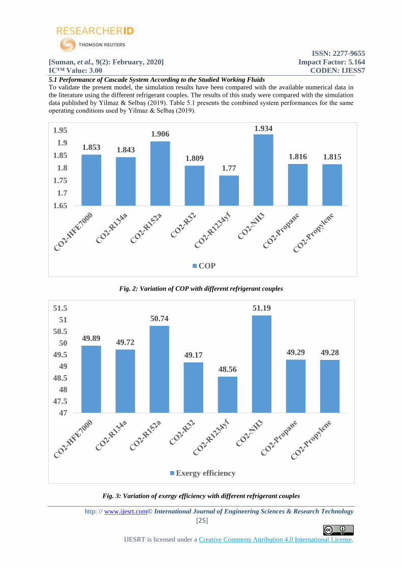
5.1 Performance of Cascade System According to the Studied Working Fluids
To validate the present model, the simulation results have been compared with the available numerical data in
the literature using the different refrigerant couples. The results of this study were compared with the simulation
data published by Yilmaz & Selbaş (2019). Table 5.1 presents the combined system performances for the same
operating conditions used by Yilmaz & Selbaş (2019).
Fig. 2: Variation of COP with different refrigerant couples
Fig. 3: Variation of exergy efficiency with different refrigerant couples
1.853 1.843
1.906
1.809
1.77
1.934
1.816 1.815
1.65
1.7
1.75
1.8
1.85
1.9
1.95
COP
49.8949.72
50.74
49.17
48.56
51.19
49.29 49.28
47
47.5
48
48.5
49
49.5
50
50.5
51
51.5
Exergy efficiency
ISSN: 2277-9655
[Suman, et al., 9(2): February, 2020] Impact Factor: 5.164
IC™ Value: 3.00 CODEN: IJESS7
http: // www.ijesrt.com© International Journal of Engineering Sciences & Research Technology
[26]
IJESRT is licensed under a Creative Commons Attribution 4.0 International License.
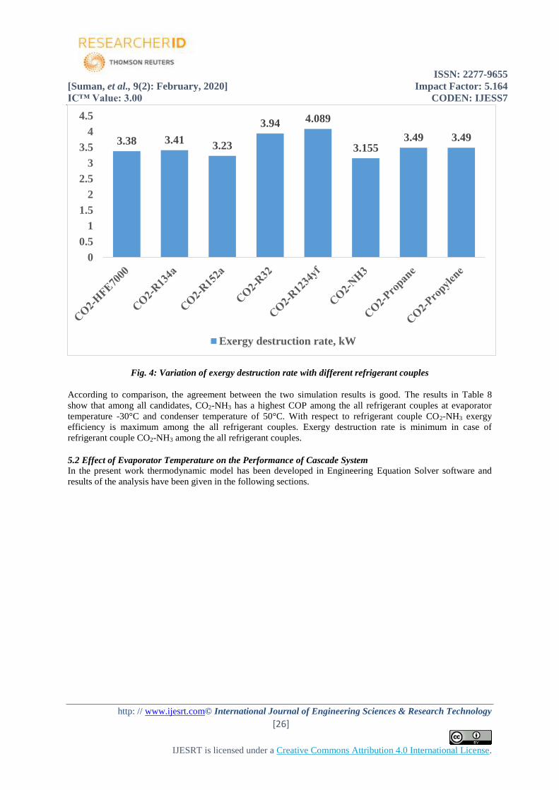
Fig. 4: Variation of exergy destruction rate with different refrigerant couples
According to comparison, the agreement between the two simulation results is good. The results in Table 8
show that among all candidates, CO2-NH3 has a highest COP among the all refrigerant couples at evaporator
temperature -30°C and condenser temperature of 50°C. With respect to refrigerant couple CO2-NH3 exergy
efficiency is maximum among the all refrigerant couples. Exergy destruction rate is minimum in case of
refrigerant couple CO2-NH3 among the all refrigerant couples.
5.2 Effect of Evaporator Temperature on the Performance of Cascade System
In the present work thermodynamic model has been developed in Engineering Equation Solver software and
results of the analysis have been given in the following sections.
3.38 3.413.23
3.94 4.089
3.1553.49 3.49
0
0.5
1
1.5
2
2.5
3
3.5
4
4.5
Exergy destruction rate, kW
ISSN: 2277-9655
[Suman, et al., 9(2): February, 2020] Impact Factor: 5.164
IC™ Value: 3.00 CODEN: IJESS7
http: // www.ijesrt.com© International Journal of Engineering Sciences & Research Technology
[27]
IJESRT is licensed under a Creative Commons Attribution 4.0 International License.
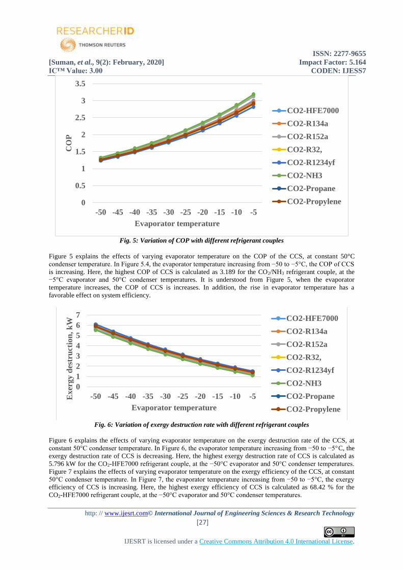
Fig. 5: Variation of COP with different refrigerant couples
Figure 5 explains the effects of varying evaporator temperature on the COP of the CCS, at constant 50°C
condenser temperature. In Figure 5.4, the evaporator temperature increasing from −50 to −5°C, the COP of CCS
is increasing. Here, the highest COP of CCS is calculated as 3.189 for the CO2/NH3 refrigerant couple, at the
−5°C evaporator and 50°C condenser temperatures. It is understood from Figure 5, when the evaporator
temperature increases, the COP of CCS is increases. In addition, the rise in evaporator temperature has a
favorable effect on system efficiency.
Fig. 6: Variation of exergy destruction rate with different refrigerant couples
Figure 6 explains the effects of varying evaporator temperature on the exergy destruction rate of the CCS, at
constant 50°C condenser temperature. In Figure 6, the evaporator temperature increasing from −50 to −5°C, the
exergy destruction rate of CCS is decreasing. Here, the highest exergy destruction rate of CCS is calculated as
5.796 kW for the CO2-HFE7000 refrigerant couple, at the −50°C evaporator and 50°C condenser temperatures.
Figure 7 explains the effects of varying evaporator temperature on the exergy efficiency of the CCS, at constant
50°C condenser temperature. In Figure 7, the evaporator temperature increasing from −50 to −5°C, the exergy
efficiency of CCS is increasing. Here, the highest exergy efficiency of CCS is calculated as 68.42 % for the
CO2-HFE7000 refrigerant couple, at the −50°C evaporator and 50°C condenser temperatures.
0
0.5
1
1.5
2
2.5
3
3.5
-50 -45 -40 -35 -30 -25 -20 -15 -10 -5
CO
P
Evaporator temperature
CO2-HFE7000
CO2-R134a
CO2-R152a
CO2-R32,
CO2-R1234yf
CO2-NH3
CO2-Propane
CO2-Propylene
0
1
2
3
4
5
6
7
-50 -45 -40 -35 -30 -25 -20 -15 -10 -5Exer
gy d
estr
uct
ion
, k
W
Evaporator temperature
CO2-HFE7000
CO2-R134a
CO2-R152a
CO2-R32,
CO2-R1234yf
CO2-NH3
CO2-Propane
CO2-Propylene
ISSN: 2277-9655
[Suman, et al., 9(2): February, 2020] Impact Factor: 5.164
IC™ Value: 3.00 CODEN: IJESS7
http: // www.ijesrt.com© International Journal of Engineering Sciences & Research Technology
[28]
IJESRT is licensed under a Creative Commons Attribution 4.0 International License.
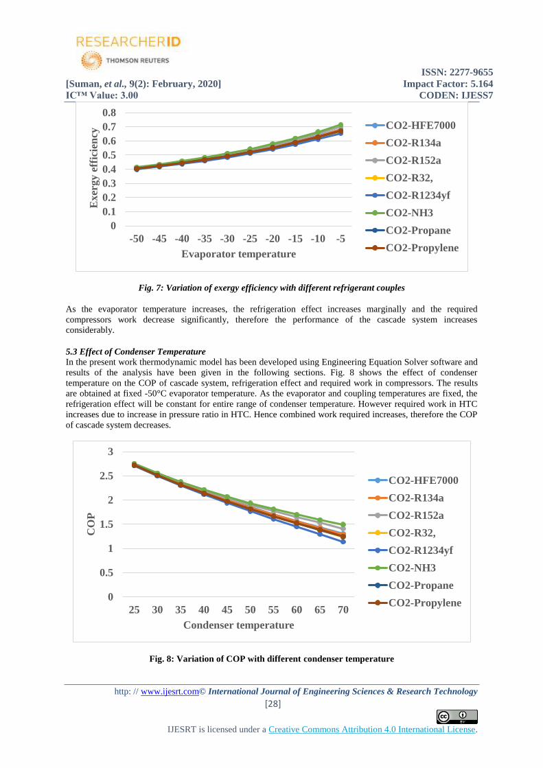
Fig. 7: Variation of exergy efficiency with different refrigerant couples
As the evaporator temperature increases, the refrigeration effect increases marginally and the required
compressors work decrease significantly, therefore the performance of the cascade system increases
considerably.
5.3 Effect of Condenser Temperature
In the present work thermodynamic model has been developed using Engineering Equation Solver software and
results of the analysis have been given in the following sections. Fig. 8 shows the effect of condenser
temperature on the COP of cascade system, refrigeration effect and required work in compressors. The results
are obtained at fixed -50°C evaporator temperature. As the evaporator and coupling temperatures are fixed, the
refrigeration effect will be constant for entire range of condenser temperature. However required work in HTC
increases due to increase in pressure ratio in HTC. Hence combined work required increases, therefore the COP
of cascade system decreases.
Fig. 8: Variation of COP with different condenser temperature
0
0.1
0.2
0.3
0.4
0.5
0.6
0.7
0.8
-50 -45 -40 -35 -30 -25 -20 -15 -10 -5
Exer
gy e
ffic
ien
cy
Evaporator temperature
CO2-HFE7000
CO2-R134a
CO2-R152a
CO2-R32,
CO2-R1234yf
CO2-NH3
CO2-Propane
CO2-Propylene
0
0.5
1
1.5
2
2.5
3
25 30 35 40 45 50 55 60 65 70
CO
P
Condenser temperature
CO2-HFE7000
CO2-R134a
CO2-R152a
CO2-R32,
CO2-R1234yf
CO2-NH3
CO2-Propane
CO2-Propylene
ISSN: 2277-9655
[Suman, et al., 9(2): February, 2020] Impact Factor: 5.164
IC™ Value: 3.00 CODEN: IJESS7
http: // www.ijesrt.com© International Journal of Engineering Sciences & Research Technology
[29]
IJESRT is licensed under a Creative Commons Attribution 4.0 International License.
Fig. 9: Variation of exergy destruction rate with different condenser temperature
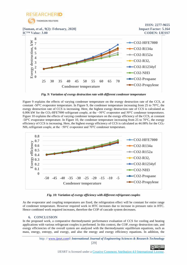
Figure 9 explains the effects of varying condenser temperature on the exergy destruction rate of the CCS, at
constant -50°C evaporator temperature. In Figure 9, the condenser temperature increasing from 25 to 70°C, the
exergy destruction rate of CCS is increasing. Here, the highest exergy destruction rate of CCS is calculated as
6.006 kW for the CO2-HFE7000 refrigerant couple, at the −50°C evaporator and 50°C condenser temperatures.
Figure 10 explains the effects of varying condenser temperature on the exergy efficiency of the CCS, at constant
-50°C evaporator temperature. In Figure 10, the condenser temperature increasing from 25 to 70°C, the exergy
efficiency of CCS is increasing. Here, the highest exergy efficiency of CCS is calculated as 44.08% for the CO2-
NH3 refrigerant couple, at the −50°C evaporator and 70°C condenser temperature.
Fig. 10: Variation of exergy efficiency with different refrigerant couples
As the evaporator and coupling temperatures are fixed, the refrigeration effect will be constant for entire range
of condenser temperature. However required work in HTC increases due to increase in pressure ratio in HTC.
Hence combined work required increases, therefore the COP of cascade system decreases.
6. CONCLUSION In the proposed work, a comparative thermodynamic performance evaluation of CCS for cooling and heating
applications with various refrigerant couples is performed. In this context, the COP, exergy destruction rate, and
exergy efficiencies of the overall system are analyzed with the thermodynamic equilibrium equations, such as
mass, energy, entropy, and exergy, and also the energy and exergy efficiency equations. In addition, the
0
1
2
3
4
5
6
7
8
25 30 35 40 45 50 55 60 65 70
Exer
gy d
estr
uct
ion
, k
W
Condenser temperature
CO2-HFE7000
CO2-R134a
CO2-R152a
CO2-R32,
CO2-R1234yf
CO2-NH3
CO2-Propane
CO2-Propylene
0
0.1
0.2
0.3
0.4
0.5
0.6
0.7
0.8
-50 -45 -40 -35 -30 -25 -20 -15 -10 -5
Exer
gy e
ffic
ien
cy
Condenser temperature
CO2-HFE7000
CO2-R134a
CO2-R152a
CO2-R32,
CO2-R1234yf
CO2-NH3
CO2-Propane
CO2-Propylene
ISSN: 2277-9655
[Suman, et al., 9(2): February, 2020] Impact Factor: 5.164
IC™ Value: 3.00 CODEN: IJESS7
http: // www.ijesrt.com© International Journal of Engineering Sciences & Research Technology
[30]
IJESRT is licensed under a Creative Commons Attribution 4.0 International License.
parametric study is performed to comprehend how evaporator and condenser temperatures influence on the
energy and exergy efficiency, and exergy destruction rate of the system for a more efficient process design.
Finally, the concluding remarks from the results of this paper can be written as follows:
1. Environment-friendly refrigerants are offered in way of ODP and GWP values.
2. The CO2 refrigerant is preferred in LTC to reach in lower temperatures.
3. The highest coefficient of performance CCS for cooling application is found as 1.934 for CO2-NH3
refrigerant couple, whereas the lowest coefficient of performance CCS is obtained as 1.777 for CO2-
R1234yf refrigerant couple.
4. The exergy efficiencies of CCS for cooling application are calculated as 49.89, 49.72, 50.74, 49.17,
48.56, 51.19, 49.29 and 49.28 for CO2-HFE7000, CO2-R134a, CO2-R152a, CO2-R32, CO2-R1234yf,
CO2 – NH3, CO2-Propane, CO2 – Propylene.
5. The largest exergy destruction rate occurs in the heat exchanger for all the CCS components. In
addition, the exergy destruction rates of the heat exchanger are close to each other in different
refrigerant pairs because it is operated at the same temperature ranges.
6. The expansion valves have the lowest exergy destruction rate among the CCS components. The COP
of CCS for cooling and heating applications decreases at a constant evaporator temperature by
increasing the condenser temperature.
7. The exergy efficiency and COP of the CCS increased positively with increased evaporator temperature.
8. The CO2- NH3 refrigerant pair is the best couple for the proposed CCS among all considered couples
according to exergy efficiency.
REFERENCES [1] Canan Cimsit, Thermodynamic Performance Analysis of the double effect absorption –vapour
compression cascade refrigeration cycle. Journal of Thermal Science and Technology, Vol.13, NO.1
(2018).
[2] Leonardo Arrieta Mondragon, Guimllermo Valencia Ochoa, Gaudy Parda Botia, Computer-Aided
Simulation of the Energetic and Exergetic Efficiency of a Two Stage Cascade Cooling Cycle,
International Journal of Applied Engineering Research, ISSN: 0973-4562, Volume 13, NO. 13 (2018),
pp.11123-11128.
[3] Jinkun Zhou, Shengjian Le, Qin Wang and Dahong Li, Optimization analyses on the performance of an
auto-cascade absorption refrigeration system operating with mixed refrigerants, International Journal of
Low- Carbon Technologies (2018), 13, 212-217.
[4] Umesh C. Rajmane, Cascade Refrigeration System: R404a-R23 Refrigerant, Asian Journal of Electrical
Sciences, Vol.6, NO. 1(2017), pp. 18-22.
[5] R.S.Mishra, Thermal modeling of three stage vapour compression cascade refrigeration system using
entropy generation principle for reducing global warming and ozone depletion using ecofriendly
refrigerants for semen preservation, International Journal of Engineering and Innovation, vol.1, issue 2
(2017), 22-28.
[6] Umesh C.Rajmane, A Review of Vapour Compression Cascade Refrigeration System, Asian Journal of
Engineering and Applied Technology, Vol.5 No.2, (2016), pp.36-39.
[7] Bhavesh Patel, Surendra Singh Kushwaha and Bhumik Modi, Thermodynamic modeling & parametric
study of a Two Stage Compression – Absorption Refrigeration System for Ice Cream Hardening Plant.
International Conference on recent advancements in Air conditioning & Refrigeration, Bhubaneswar,
India, 10-12 Nov (2016).
[8] Manoj Dixit, S.C. Kaushik, Akilesh Arrora, Energy & Exergy Analysis of Absorption – Compression
Cascade refrigeration system, Journal of Thermal Engg. 5(2016), pp 995-1006.
[9] J .Alberto Dopazo, Jose Fernandez-Seara-Theoretical analysis of a CO2-NH3 Cascade refrigeration
system for cooling applications at low temperature, applied thermal engineering 29 (2009) 1577-1583.
[10] J. Fernandez, Vapour compression –absorption cascade refrigeration system, Applied Thermal
engineering 26(2006) 502-512.
[11] L .Kauouani, E-Nehdi, Cooling performance and energy saving of a compression – absorption
refrigeration system assisted by geothermal energy applied thermal engineering, 26 (2006) 288-294.
ISSN: 2277-9655
[Suman, et al., 9(2): February, 2020] Impact Factor: 5.164
IC™ Value: 3.00 CODEN: IJESS7
http: // www.ijesrt.com© International Journal of Engineering Sciences & Research Technology
[31]
IJESRT is licensed under a Creative Commons Attribution 4.0 International License.
[12] T .Lee, C. Liu, T .Chen ,Thermodynamic analysis of optimal condensing temperature of cascade
condenser in CO2/NH3 Cascade refrigeration system, international journal of refrigeration 29 (2006)
1100-1108.
[13] A. Kilicarlsan, An experimental investigation of a different type vapour compression cascade
refrigeration system .Applied Thermal engineering 24 (2004) pp.2611-2626.
[14] G.L. Molenaar use of R22/23 in lieu of R-502/13 in a cascade refrigeration system, in: Proceedings,
Annual international journal of Energy Research 26 (8) (2002), 763-774.
[15] Kanoglu, Mehmet, Exergy analysis of multistage cascade refrigeration cycle used for natural gas
liquefaction.” International Journal of energy Research 26 (2002): 763-74.
[16] Zhili Sun, Youcai Liang, Shengchun Liu, Weichuan Ji, Runqing Zang, Rongzhen Liang, Zhikai Guo,
Comparative analysis of thermodynamic performance of a cascade refrigeration system for refrigerant
couples R41/R404A and R23/R404A, 184, 19-25, 2016.
[17] A. D. Parekh, P. R. Tailor, Thermodynamic Analysis of Cascade Refrigeration System Using R12-R13,
R290-R23 and R404A-R23, International Journal of Mechanical and Mechatronics Engineering, 8(8),
1351-1356.
Recommended


![JESRT: 8(1), January, 2019 ISSN: 2277-9655 I nternational …ijesrt.com/issues /Archive-2019/january-2019/38.pdf · proves potential in the management of urolithiasis [6, 7]. Antioxidants](https://img.dokumen.tips/doc/110x75/5caea69188c99323378c8bd8/jesrt-81-january-2019-issn-2277-9655-i-nternational-archive-2019january-201938pdf.jpg)