NOTE: Please read all instructions carefully before using this
product
Table of Contents
Safety Notice
Hardware Pack
Assembly Instruction
Parts List
Resistance Chart
Warranty
Ordering Parts
Model IVK 5500
Retain This Manual for Reference
10-1-04
OWNER'S MANUAL
IVK 5500 PERSONAL TRAINER
IMPEX FITNESS PRODUCTS
14777 DON JULIAN RD., CITY OF INDUSTRY, CA 91746 Tel: (800) 999-8899 Fax: (626) 961-9966
www.impex-fitness.com [email protected]

TABLE OF CONTENTS BEFORE YOU BEGIN...................................................................................... 1 IMPORTANT SAFETY NOTICE....................................................................… 2 HARDWARE PACK…….......….....................................................................… 4 ASSEMBLY INSTRUCTIONS........................................................................... 8
EXPLODED DIAGRAM……………………………………………………………… 29 PARTS LIST...................................................................................................... 30 RESISTANCE CHART…………........................................................................ 32 WARRANTY.................................................................................................…. 33 ORDERING PARTS.......................................................................................… 33
BEFORE YOU BEGIN Thank you for selecting the IVANKO IVK-5500 PERSONAL TRAINER by IMPEX FITNESS PRODUCTS. For your safety and benefit, read this manual carefully before using the machine. As a manufacturer, we are committed to provide you complete customer satisfaction. If you have any questions, or find there are missing or damaged parts, we guarantee you complete satisfaction through direct assistance from our factory. To avoid unnecessary delays, please call our TOLL-FREE customer service number. Our Customer Service Agents will provide immediate assistance to you.
1
Toll-Free Customer Service Number 1-800-999-8899
Mon. - Fri. 9 a.m. - 5 p.m. PST www.impex-fitness.com [email protected]

IMPORTANT SAFETY NOTICE PRECAUTIONS This exercise machine is built for optimum safety. However, certain precautions apply whenever you operate a piece of exercise equipment. Be sure to read the entire manual before you assemble or operate your machine. In particular, note the following safety precautions: 1. Keep children and pets away from the machine at all times. DO NOT leave children unattended in the same room with the machine. 2. Only one person at a time should use the machine. 3. If the user experiences dizziness, nausea, chest pain, or any other abnormal symptoms, STOP the workout at once. CONSULT A PHYSICIAN IMMEDIATELY. 4. Position the machine on a clear, leveled surface. DO NOT use the machine near water or outdoors. 5. Keep hands away from all moving parts. 6. Always wear appropriate workout clothing when exercising. DO NOT wear robes or other clothing that could become caught in the machine. Running or aerobic shoes are also required when using the machine. 7. Use the machine only for its intended use. DO NOT use attachments not
recommended by the manufacturer. 8. Do not place any sharp object around the machine. 9. Disabled person should not use the machine without a qualified person or physician in attendance. 10. Before using the machine to exercise, always do stretching exercises to properly warm up. 11. Never operate the machine if the machine is not functioning properly. 12. Maximum user weight capacity: 300 lbs. WARNING: BEFORE BEGINNING ANY EXERCISE PROGRAM, CONSULT YOUR PHYSICIAN. THIS IS ESPECIALLY IMPORTANT FOR INDIVIDUALS OVER THE AGE OF 35 OR PERSONS WITH PRE-EXISTING HEALTH PROBLEMS. READ ALL INSTRUCTIONS BEFORE USING ANY FITNESS EQUIPMENT. IMPEX INC. ASSUMES NO RESPONSIBILITY FOR PERSONAL INJURY OR PROPERTY DAMAGE SUSTAINED BY OR THROUGH THE USE OF THIS PRODUCT. SAVE THESE INSTRUCTIONS.
2
WARNING LABELS PLACEMENT
The Warning Labels shown here have been placed on Rear Base and Upper Frame. If the labels are missing or illegible, please call customer service at 1-800-999-8899 for replacement. Apply the label in the location shown.
3
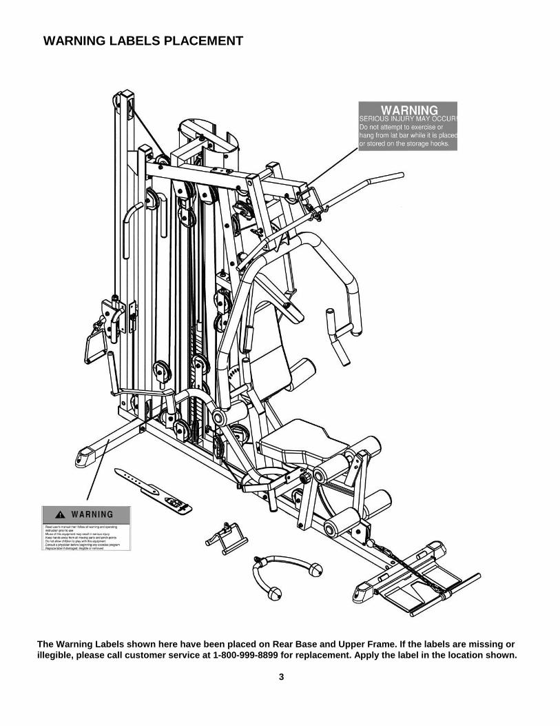
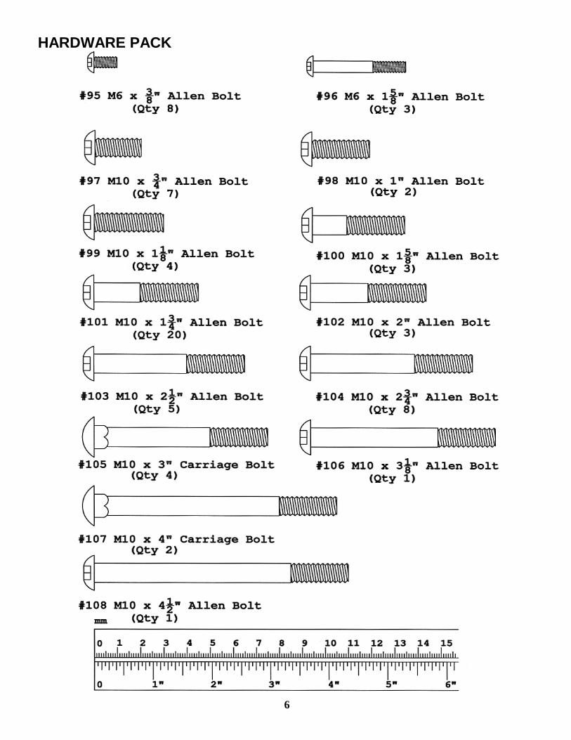
HARDWARE PACK
4
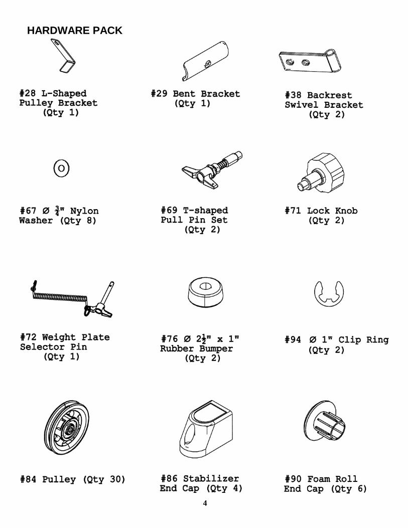
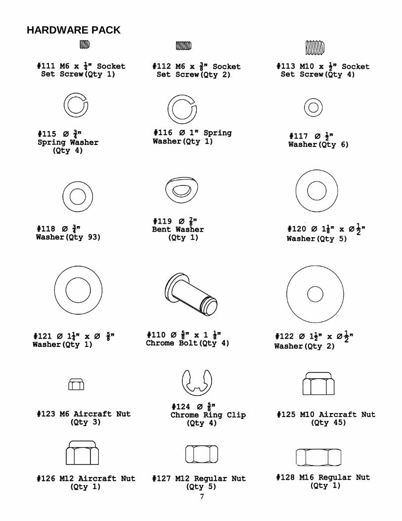
HARDWARE PACK
5
HARDWARE PACK
6
HARDWARE PACK
7
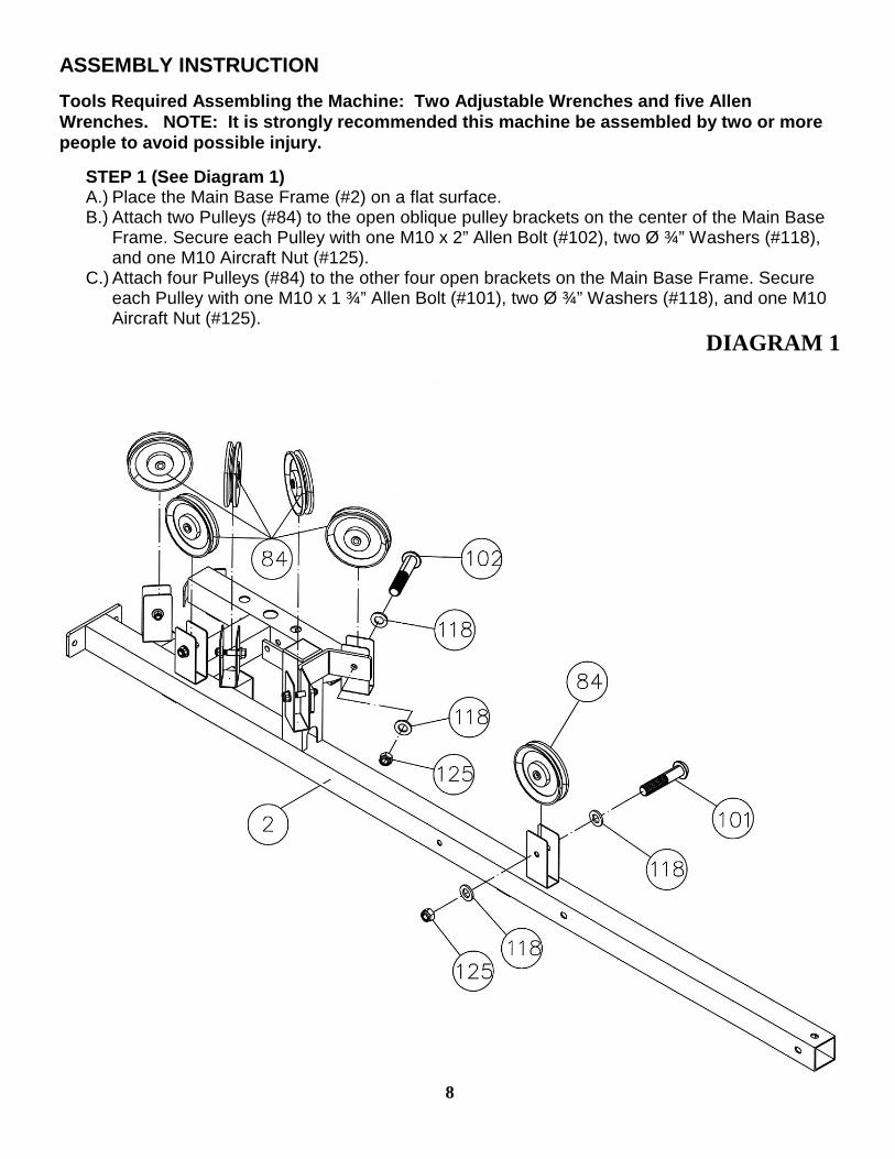
ASSEMBLY INSTRUCTION Tools Required Assembling the Machine: Two Adjustable Wrenches and five Allen Wrenches. NOTE: It is strongly recommended this machine be assembled by two or more people to avoid possible injury. STEP 1 (See Diagram 1)
A.) Place the Main Base Frame (#2) on a flat surface. B.) Attach two Pulleys (#84) to the open oblique pulley brackets on the center of the Main Base
Frame. Secure each Pulley with one M10 x 2” Allen Bolt (#102), two Ø ¾” Washers (#118), and one M10 Aircraft Nut (#125).
C.) Attach four Pulleys (#84) to the other four open brackets on the Main Base Frame. Secure each Pulley with one M10 x 1 ¾” Allen Bolt (#101), two Ø ¾” Washers (#118), and one M10 Aircraft Nut (#125).
DIAGRAM 1
8
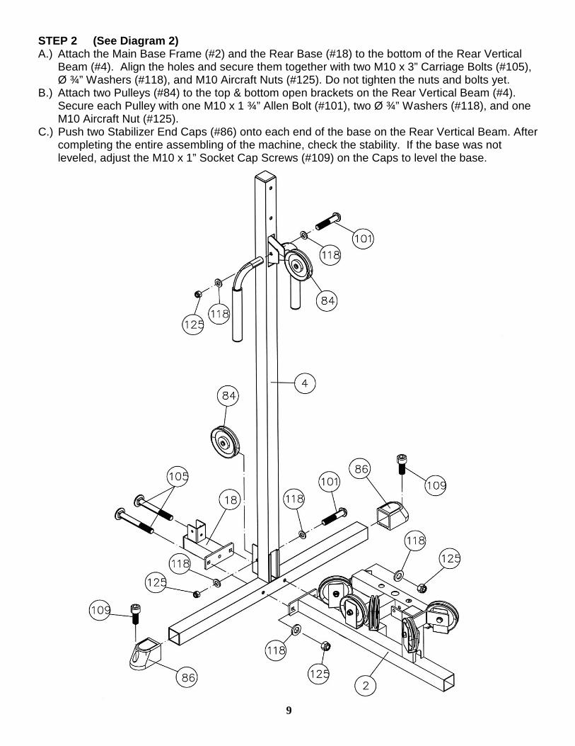
STEP 2 (See Diagram 2) A.) Attach the Main Base Frame (#2) and the Rear Base (#18) to the bottom of the Rear Vertical
Beam (#4). Align the holes and secure them together with two M10 x 3” Carriage Bolts (#105), Ø ¾” Washers (#118), and M10 Aircraft Nuts (#125). Do not tighten the nuts and bolts yet.
B.) Attach two Pulleys (#84) to the top & bottom open brackets on the Rear Vertical Beam (#4). Secure each Pulley with one M10 x 1 ¾” Allen Bolt (#101), two Ø ¾” Washers (#118), and one M10 Aircraft Nut (#125).
C.) Push two Stabilizer End Caps (#86) onto each end of the base on the Rear Vertical Beam. After completing the entire assembling of the machine, check the stability. If the base was not leveled, adjust the M10 x 1” Socket Cap Screws (#109) on the Caps to level the base.
9

STEP 3 (See Diagram 3) A.) Attach the Front Vertical Beam (#3) to the Main Base Frame (#2). Secure it with one M10 x 2 ¾”
Allen Bolt (#104), two Ø ¾” Washers (#118), and one M10 Aircraft Nut (#125). Do not tighten the nut and bolt yet.
B.) Attach a Pulley to the bracket on the upper Front Vertical Beam. Attach a L-shaped Bracket (#28) to the Pulley. Secure them with one M10 x 2” Allen Bolt (#102), two Ø ¾” Washers (#118), and one M10 Aircraft Nut (#125).
C.) Place two Pulleys in the two openings on the Front Vertical Beam. Secure each Pulley with one M10 x 2 ½” Allen Bolt (#103), two Ø ¾” Washers (#118), and one M10 Aircraft Nut (#125).
D.) Insert a Pulley Pre-tensioner (#24) through the hole on the back of Front Vertical Beam. Secure it with two Ø 1 1/8” x Ø ½” Washers (#120) and M12 Regular Nuts (#127).
10
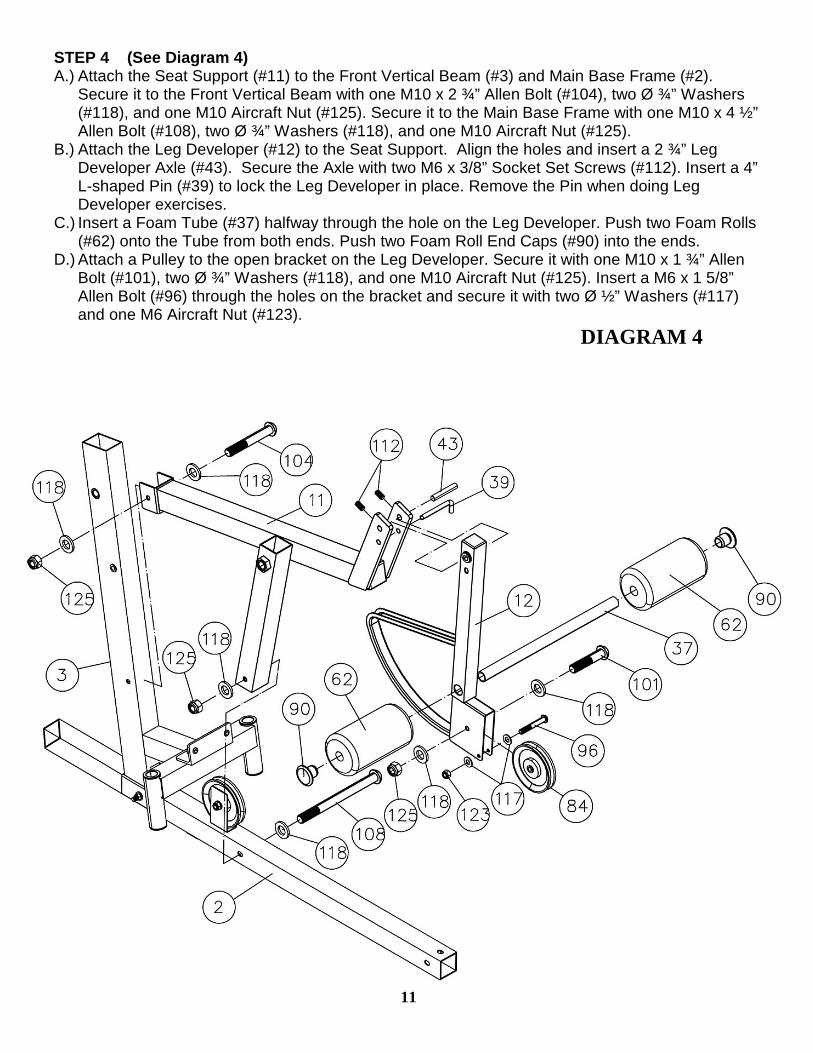
STEP 4 (See Diagram 4) A.) Attach the Seat Support (#11) to the Front Vertical Beam (#3) and Main Base Frame (#2).
Secure it to the Front Vertical Beam with one M10 x 2 ¾” Allen Bolt (#104), two Ø ¾” Washers (#118), and one M10 Aircraft Nut (#125). Secure it to the Main Base Frame with one M10 x 4 ½” Allen Bolt (#108), two Ø ¾” Washers (#118), and one M10 Aircraft Nut (#125).
B.) Attach the Leg Developer (#12) to the Seat Support. Align the holes and insert a 2 ¾” Leg Developer Axle (#43). Secure the Axle with two M6 x 3/8” Socket Set Screws (#112). Insert a 4” L-shaped Pin (#39) to lock the Leg Developer in place. Remove the Pin when doing Leg Developer exercises.
C.) Insert a Foam Tube (#37) halfway through the hole on the Leg Developer. Push two Foam Rolls (#62) onto the Tube from both ends. Push two Foam Roll End Caps (#90) into the ends.
D.) Attach a Pulley to the open bracket on the Leg Developer. Secure it with one M10 x 1 ¾” Allen Bolt (#101), two Ø ¾” Washers (#118), and one M10 Aircraft Nut (#125). Insert a M6 x 1 5/8” Allen Bolt (#96) through the holes on the bracket and secure it with two Ø ½” Washers (#117) and one M6 Aircraft Nut (#123).
DIAGRAM 4
11
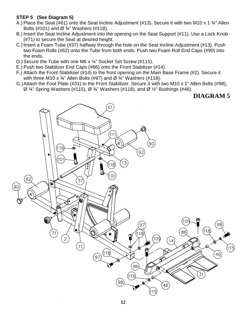
STEP 5 (See Diagram 5) A.) Place the Seat (#61) onto the Seat Incline Adjustment (#13). Secure it with two M10 x 1 ¾” Allen
Bolts (#101) and Ø ¾” Washers (#118). B.) Insert the Seat Incline Adjustment into the opening on the Seat Support (#11). Use a Lock Knob
(#71) to secure the Seat at desired height. C.) Insert a Foam Tube (#37) halfway through the hole on the Seat Incline Adjustment (#13). Push
two Foam Rolls (#62) onto the Tube from both ends. Push two Foam Roll End Caps (#90) into the ends.
D.) Secure the Tube with one M6 x ¼” Socket Set Screw (#111). E.) Push two Stabilizer End Caps (#86) onto the Front Stabilizer (#14). F.) Attach the Front Stabilizer (#14) to the front opening on the Main Base Frame (#2). Secure it
with three M10 x ¾” Allen Bolts (#97) and Ø ¾” Washers (#118). G.) Attach the Foot Plate (#31) to the Front Stabilizer. Secure it with two M10 x 1” Allen Bolts (#98),
Ø ¾” Spring Washers (#115), Ø ¾” Washers (#118), and Ø ½” Bushings (#46). DIAGRAM 5
12
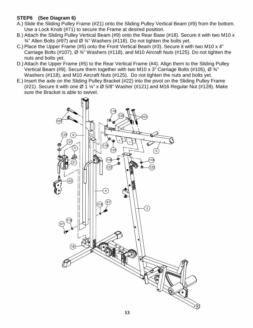
STEP6 (See Diagram 6) A.) Slide the Sliding Pulley Frame (#21) onto the Sliding Pulley Vertical Beam (#9) from the bottom.
Use a Lock Knob (#71) to secure the Frame at desired position. B.) Attach the Sliding Pulley Vertical Beam (#9) onto the Rear Base (#18). Secure it with two M10 x
¾” Allen Bolts (#97) and Ø ¾” Washers (#118). Do not tighten the bolts yet. C.) Place the Upper Frame (#5) onto the Front Vertical Beam (#3). Secure it with two M10 x 4”
Carriage Bolts (#107), Ø ¾” Washers (#118), and M10 Aircraft Nuts (#125). Do not tighten the nuts and bolts yet.
D.) Attach the Upper Frame (#5) to the Rear Vertical Frame (#4). Align them to the Sliding Pulley Vertical Beam (#9). Secure them together with two M10 x 3” Carriage Bolts (#105), Ø ¾” Washers (#118), and M10 Aircraft Nuts (#125). Do not tighten the nuts and bolts yet.
E.) Insert the axle on the Sliding Pulley Bracket (#22) into the pivot on the Sliding Pulley Frame (#21). Secure it with one Ø 1 ¼” x Ø 5/8” Washer (#121) and M16 Regular Nut (#128). Make sure the Bracket is able to swivel.
13
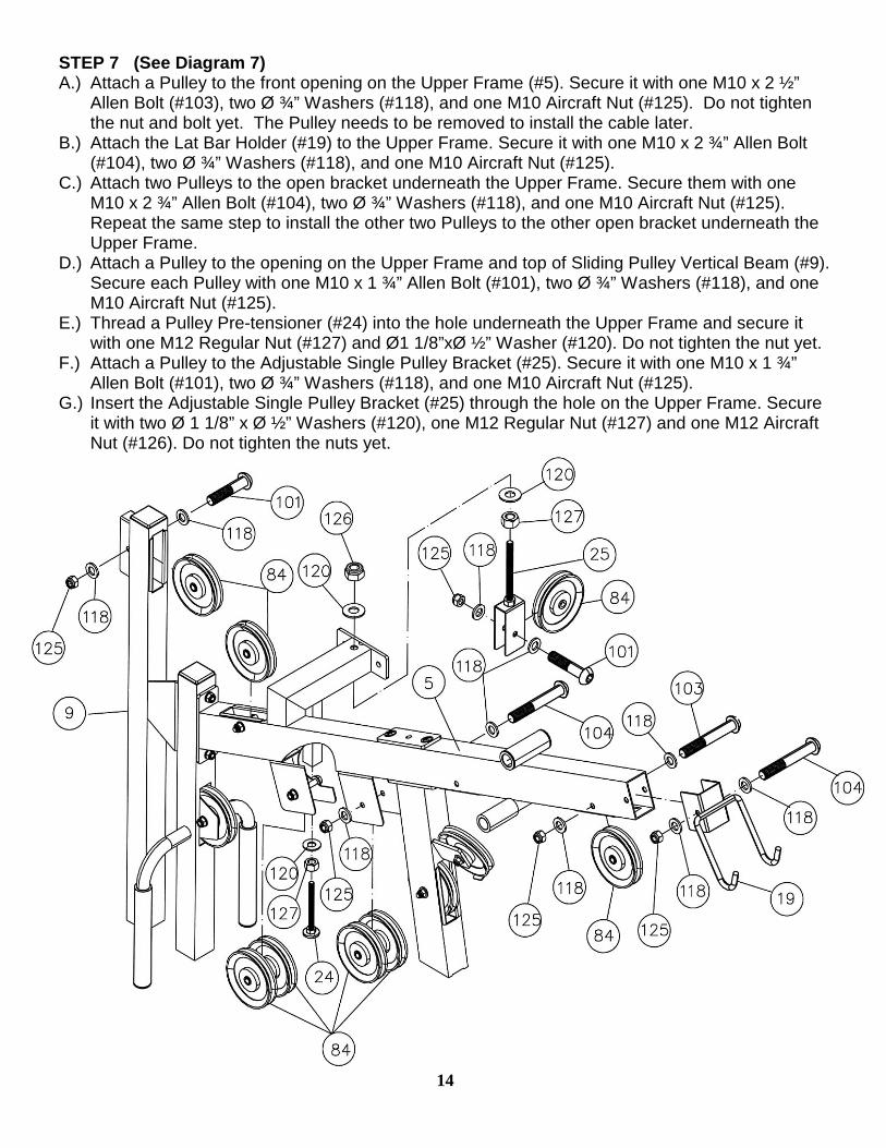
STEP 7 (See Diagram 7) A.) Attach a Pulley to the front opening on the Upper Frame (#5). Secure it with one M10 x 2 ½”
Allen Bolt (#103), two Ø ¾” Washers (#118), and one M10 Aircraft Nut (#125). Do not tighten the nut and bolt yet. The Pulley needs to be removed to install the cable later.
B.) Attach the Lat Bar Holder (#19) to the Upper Frame. Secure it with one M10 x 2 ¾” Allen Bolt (#104), two Ø ¾” Washers (#118), and one M10 Aircraft Nut (#125).
C.) Attach two Pulleys to the open bracket underneath the Upper Frame. Secure them with one M10 x 2 ¾” Allen Bolt (#104), two Ø ¾” Washers (#118), and one M10 Aircraft Nut (#125). Repeat the same step to install the other two Pulleys to the other open bracket underneath the Upper Frame.
D.) Attach a Pulley to the opening on the Upper Frame and top of Sliding Pulley Vertical Beam (#9). Secure each Pulley with one M10 x 1 ¾” Allen Bolt (#101), two Ø ¾” Washers (#118), and one M10 Aircraft Nut (#125).
E.) Thread a Pulley Pre-tensioner (#24) into the hole underneath the Upper Frame and secure it with one M12 Regular Nut (#127) and Ø1 1/8”xØ ½” Washer (#120). Do not tighten the nut yet.
F.) Attach a Pulley to the Adjustable Single Pulley Bracket (#25). Secure it with one M10 x 1 ¾” Allen Bolt (#101), two Ø ¾” Washers (#118), and one M10 Aircraft Nut (#125).
G.) Insert the Adjustable Single Pulley Bracket (#25) through the hole on the Upper Frame. Secure it with two Ø 1 1/8” x Ø ½” Washers (#120), one M12 Regular Nut (#127) and one M12 Aircraft Nut (#126). Do not tighten the nuts yet.
14
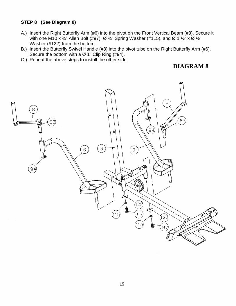
STEP 8 (See Diagram 8) A.) Insert the Right Butterfly Arm (#6) into the pivot on the Front Vertical Beam (#3). Secure it
with one M10 x ¾” Allen Bolt (#97), Ø ¾” Spring Washer (#115), and Ø 1 ½” x Ø ½” Washer (#122) from the bottom.
B.) Insert the Butterfly Swivel Handle (#8) into the pivot tube on the Right Butterfly Arm (#6). Secure the bottom with a Ø 1” Clip Ring (#94).
C.) Repeat the above steps to install the other side. DIAGRAM 8
15

STEP 9 (See Diagram 9) A.) Attach the Bench Press Base (#32) to the pivot on the Upper Frame (#5). Align the holes and
insert a 8” Bench Press Axle (#44) through the holes. Secure the Axle with two M10 x ½” Socket Set Screws (#113).
B.) Attach the Bench Press Arm (#1) to the Bench Press Base (#32). Align the holes and insert a 8” Bench Press Axle (#44) through the holes. Secure the Axle with two M10 x ½” Socket Set Screws (#113).
C.) Thread a T-shaped Pull Pin Set (#69) through the hole on the Bench Press Base (#32) to obtain the desired Bench Press position.
D.) Attach two Pulleys (#84) to the open bracket on the back of Bench Press Base (#32). Secure them with one M10 x 2 ¾” Allen Bolt (#104), two Ø ¾” Washers (#118), and one M10 Aircraft Nut (#125).
16
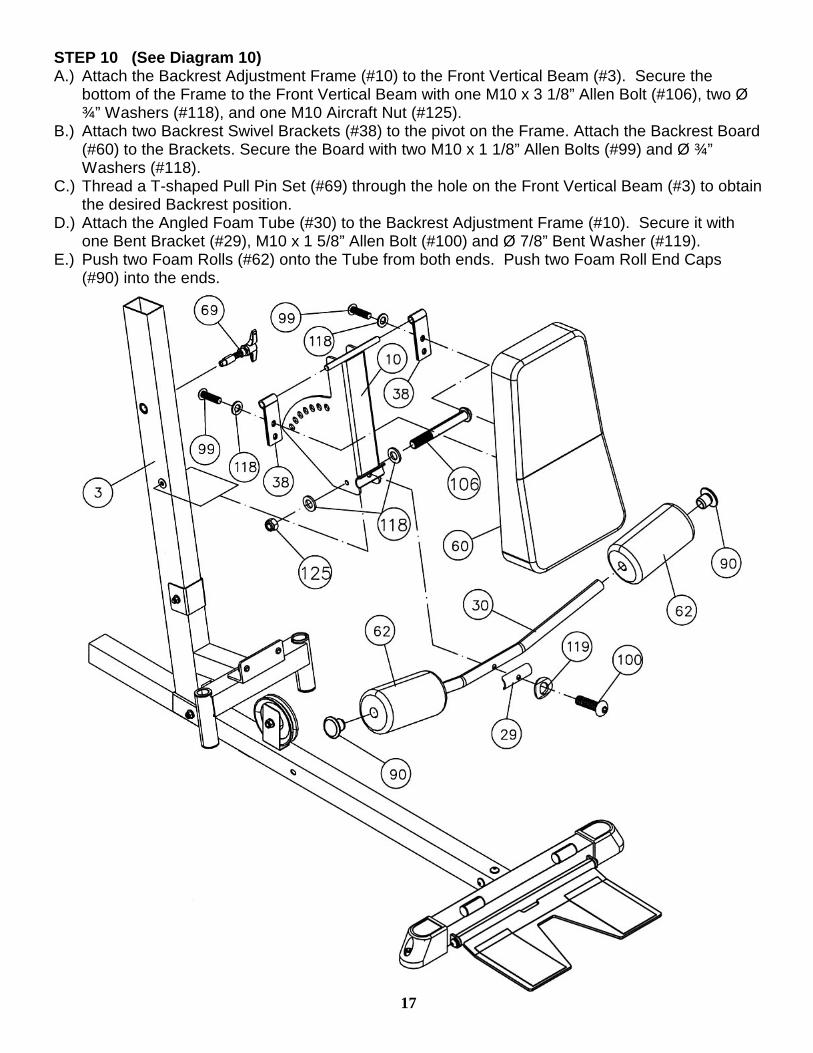
STEP 10 (See Diagram 10) A.) Attach the Backrest Adjustment Frame (#10) to the Front Vertical Beam (#3). Secure the
bottom of the Frame to the Front Vertical Beam with one M10 x 3 1/8” Allen Bolt (#106), two Ø ¾” Washers (#118), and one M10 Aircraft Nut (#125).
B.) Attach two Backrest Swivel Brackets (#38) to the pivot on the Frame. Attach the Backrest Board (#60) to the Brackets. Secure the Board with two M10 x 1 1/8” Allen Bolts (#99) and Ø ¾” Washers (#118).
C.) Thread a T-shaped Pull Pin Set (#69) through the hole on the Front Vertical Beam (#3) to obtain the desired Backrest position.
D.) Attach the Angled Foam Tube (#30) to the Backrest Adjustment Frame (#10). Secure it with one Bent Bracket (#29), M10 x 1 5/8” Allen Bolt (#100) and Ø 7/8” Bent Washer (#119).
E.) Push two Foam Rolls (#62) onto the Tube from both ends. Push two Foam Roll End Caps (#90) into the ends.
17
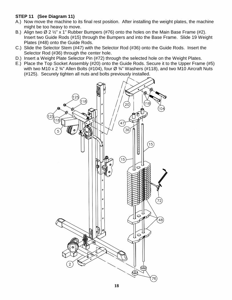
STEP 11 (See Diagram 11) A.) Now move the machine to its final rest position. After installing the weight plates, the machine
might be too heavy to move. B.) Align two Ø 2 ½” x 1” Rubber Bumpers (#76) onto the holes on the Main Base Frame (#2).
Insert two Guide Rods (#15) through the Bumpers and into the Base Frame. Slide 19 Weight Plates (#48) onto the Guide Rods.
C.) Slide the Selector Stem (#47) with the Selector Rod (#36) onto the Guide Rods. Insert the Selector Rod (#36) through the center hole.
D.) Insert a Weight Plate Selector Pin (#72) through the selected hole on the Weight Plates. E.) Place the Top Socket Assembly (#20) onto the Guide Rods. Secure it to the Upper Frame (#5)
with two M10 x 2 ¾” Allen Bolts (#104), four Ø ¾” Washers (#118), and two M10 Aircraft Nuts (#125). Securely tighten all nuts and bolts previously installed.
18

STEP 12 (See Diagram 12) A.) Attach two Pulleys to each Angled Double Floating Pulley Bracket (#26). Secure each Pulley
with one M10 x 1 ¾” Allen Bolt (#101), two ∅ 3/4” Washers (#118), and one M10 Aircraft Nut (#125). Do not tighten the nuts and bolts yet. The Pulleys may need to be removed when installing the Cables.
B.) Attach one Pulley to a Single Pulley Bracket (#23). C.) Attach two Pulleys to the Double Floating Pulley Brackets (#27).
DIAGRAM 12
19
STEP 13 Install the Upper Cable (See Diagram 13)
A.) Attach the tip of the 161” Upper Cable (#52) to the Pulley (#84) on the front of the Upper Frame (#5). Insert the Cable into the Frame through the tube to the second opening. Remove the Pulley to get the Cable out then reinstall the Pulley.
B.) Draw the Cable around the Pulley then down to the right Pulley on the back of the Bench Press Base (#32). Draw the Cable around the right Pulley then to the Pulley on the front of the Front Vertical Beam (#3).
C.) Draw the Cable around the Pulley then back to the left Pulley on the back of the Bench Press Base (#32).
D.) Draw the Cable around the left Pulley then to the Pulley in the upper open slot on the Front Vertical Beam (#3).
E.) Draw the Cable underneath the Pulley then pull upward to the first right Pulley underneath the Upper Frame. Draw the Cable over the Pulley to the second right Pulley underneath the Upper Frame.
F.) Draw the Cable over the Pulley then pull downward. Attach the Cable to the upper Pulley on an Angled Double Floating Pulley Bracket (#26) installed in Step12. Attach the Bracket underneath the Pulley Pre-tensioner (#24).
G.) Draw the Cable underneath the Pulley then pull upward to the Pulley on the Adjustable Single Pulley Bracket installed in Step-7G. Let the Double Floating Pulley Bracket (#26) hanging for now.
H.) Draw the Cable around the Pulley then pull downward to the Selector Rod (#36). I.) Attach the end of the Cable to a M12 x 1” Split Bolt (#42). Thread the Split Bolt through a Ø
1” Spring Washer (#116) and the ring on the Weight Plate Selector Pin (#72) into the Selector Rod (#36).
J.) Connect the Lat Bar (#17) to the Cable Strap Bracket with a Hook (#41). K.) Place the Lat Bar onto the Lat Bar Holder.
20
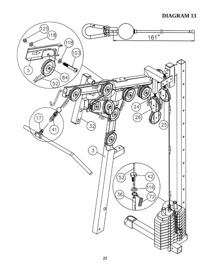
DIAGRAM 13
21

STEP 14 Install the High-Low Station Cable (See Diagram 14)
A.) Insert the tip of the 262” High-Low Cable (#53) in between the pre-assembled two
Small Pulleys (#85) on the Sliding Pulley Frame (#22). Note: You might need to remove one of the Pulleys in able to see the hole.
B.) Draw the Cable through the Sliding Pulley Frame then pull upward to the Pulley on the top opening of the Sliding Pulley Vertical Beam (#9).
C.) Draw the Cable over the Pulley then pull forward to the Pulley on the rear opening on the Upper Frame (#5).
D.) Draw the Cable over the Pulley then pull downward. Attach the Cable to the Pulley on the Single Floating Pulley Bracket (#23) installed in Step12.
E.) Draw the Cable underneath the Pulley then pull upward to the Pulley on the upper Rear Vertical Frame (#4). Let the Single Floating Pulley Bracket (#23) hanging for now.
F.) Draw the Cable around the Pulley then drop the Cable inside the tube downward through the Rear Vertical Frame to the Pulley on the bottom opening. Remove the Pulley to get the Cable out then reinstall the Pulley. Draw the Cable underneath the Pulley then pull upward to the bracket on the Sliding Pulley Frame (#21).
G.) Attach the Cable ball tip to the bracket. Secure the bracket with one M10 x 1 1/8” Allen Bolt (#99) and M10 Aircraft Nut (#125).
H.) Connect the Single Handle (#35) to the end of the Cable with a Hook (#41).
22
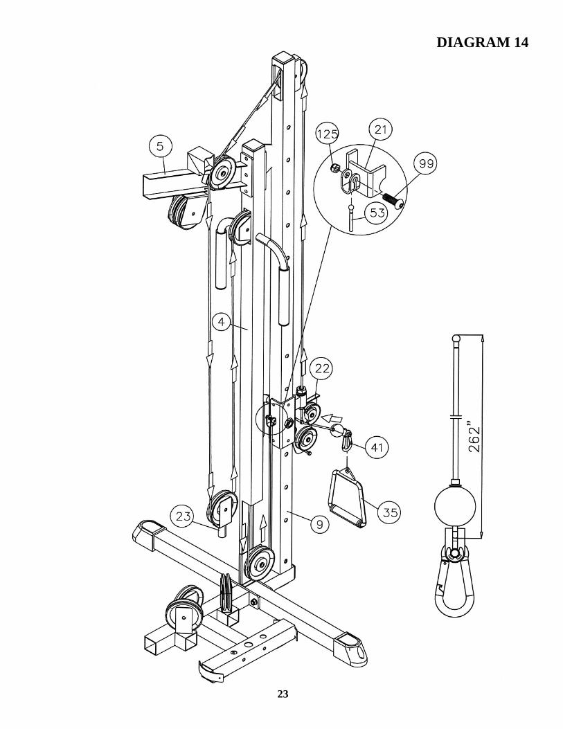
DIAGRAM 14
23
STEP 15 Install the Lower & AB Cable (See Diagram 15) A.) Insert the 265” Lower Cable (#54) underneath the Pulley on the Leg Developer (#12). B.) Draw the Cable underneath the Pulley along the Main Base Frame (#2) to the Pulley under
the Seat. Continue drawing the Cable along the Base Frame through the opening on the bottom of the Front Vertical Beam (#3) to the Pulley on the rear of Main Base Frame.
C.) Draw the Cable underneath the Pulley then pull upward to the left Pulley underneath the Upper Frame (#5). Draw the Cable around the Pulley then pull downward. Attach the Cable to the upper Pulley on the Double Floating Pulley Brackets (#27) previously installed in Step-12.
D.) Draw the Cable around the Pulley then upward to the left Pulley underneath the Upper Frame. Let the Bracket (#27) hanging for now.
E.) Draw the Cable around the Pulley then downward. Attach the Cable to the upper Pulley on an Angled Double Floating Pulley Bracket (#26) previously installed in Step-12.
F.) Draw the Cable underneath the Pulley then upward to the Pulley in the middle opening on the Front Vertical Beam. Draw the Cable over the Pulley and through the opening.
G.) Slide a Ball Stopper (#70) onto the Cable. Slide and Pull the Cable Strap Bracket (#45) onto the end of the Cable. Secure the Bracket with a Ø 5/8” x 1 1/8” Chrome Bolt (#110) and Ø 5/8” Chrome Ring Clip (#124). Connect a Hook (#41) to the Bracket.
H.) Connect the AB Strap (#58) or Triceps Rope (#59) to the Hook for various exercises. I.) Use a Hook (#41) to connect a Chain (#40) to the clip on the end of the Cable in front of the
Leg Developer (#12). J.) Use a Hook (#41) to connect the Ankle Strap (#57), Double Handle (#34), or Shiver Bar (#33)
to the Chain for various exercises. K.) Note: After completing the entire Cable installations, adjust the tightness of the Cable Loop
System by adjusting the height of the Pulley Pre-tensioner (#24). Lower the Pre-tensioner so it touches the top of the Pulley Bracket.
24

DIAGRAM 15
25
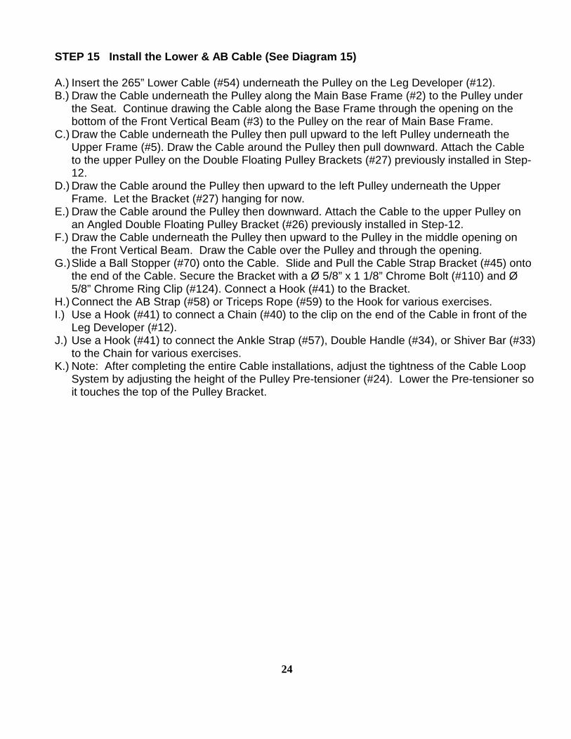
STEP 16 Install the Butterfly Cable (See Diagram 16) A.) Attach one end of the 99” Butterfly Cable (#55) to a Cable Strap Bracket (#45). Place a Ø
7/8” x ½” Spacer (#80) in between the opening. Secure the Bracket to the Right Butterfly (#6) with a M10 x 1 5/8” Allen Bolt (#100), two Ø ¾” Washers (#118), and one M10 Aircraft Nut (#125).
B.) Pull the Cable towards the back of the machine to the right oblique Pulley on the Main Base Frame behind the Front Vertical Beam.
C.) Draw the Cable underneath the Pulley then pull upward to the lower Pulley on the Angled Double Floating Pulley Bracket (#26). Draw the Cable around the Pulley then downward to the left oblique Pulley on the Main Base Frame.
D.) Draw the Cable underneath the Pulley then pull towards the Left Butterfly (#7). E.) Repeat Step A above to secure the end of the Cable to the Left Butterfly.
26
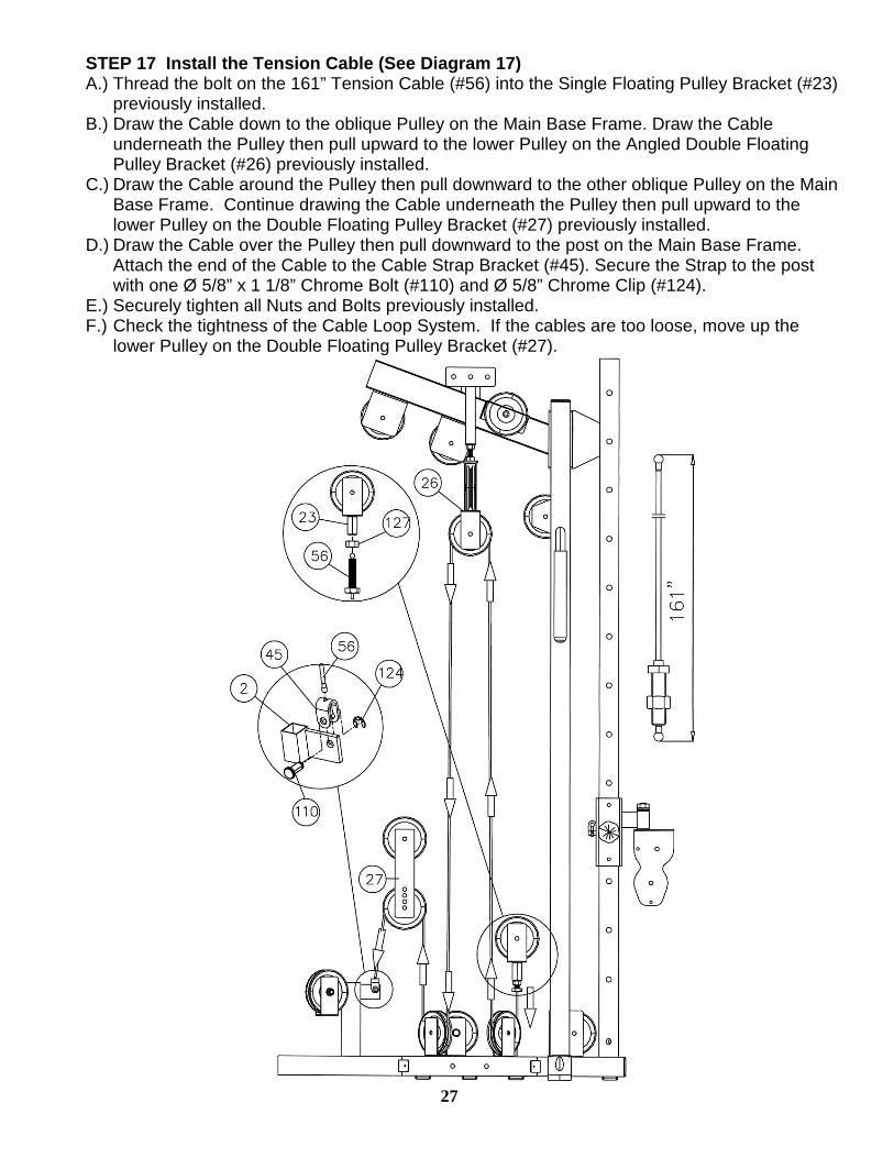
STEP 17 Install the Tension Cable (See Diagram 17) A.) Thread the bolt on the 161” Tension Cable (#56) into the Single Floating Pulley Bracket (#23)
previously installed. B.) Draw the Cable down to the oblique Pulley on the Main Base Frame. Draw the Cable
underneath the Pulley then pull upward to the lower Pulley on the Angled Double Floating Pulley Bracket (#26) previously installed.
C.) Draw the Cable around the Pulley then pull downward to the other oblique Pulley on the Main Base Frame. Continue drawing the Cable underneath the Pulley then pull upward to the lower Pulley on the Double Floating Pulley Bracket (#27) previously installed.
D.) Draw the Cable over the Pulley then pull downward to the post on the Main Base Frame. Attach the end of the Cable to the Cable Strap Bracket (#45). Secure the Strap to the post with one Ø 5/8” x 1 1/8” Chrome Bolt (#110) and Ø 5/8” Chrome Clip (#124).
E.) Securely tighten all Nuts and Bolts previously installed. F.) Check the tightness of the Cable Loop System. If the cables are too loose, move up the
lower Pulley on the Double Floating Pulley Bracket (#27).
27
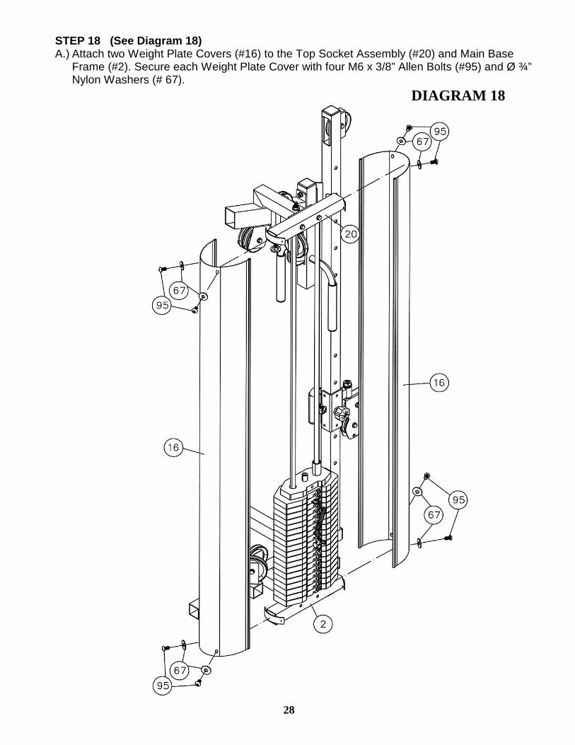
STEP 18 (See Diagram 18) A.) Attach two Weight Plate Covers (#16) to the Top Socket Assembly (#20) and Main Base
Frame (#2). Secure each Weight Plate Cover with four M6 x 3/8” Allen Bolts (#95) and Ø ¾” Nylon Washers (# 67).
DIAGRAM 18
28

29
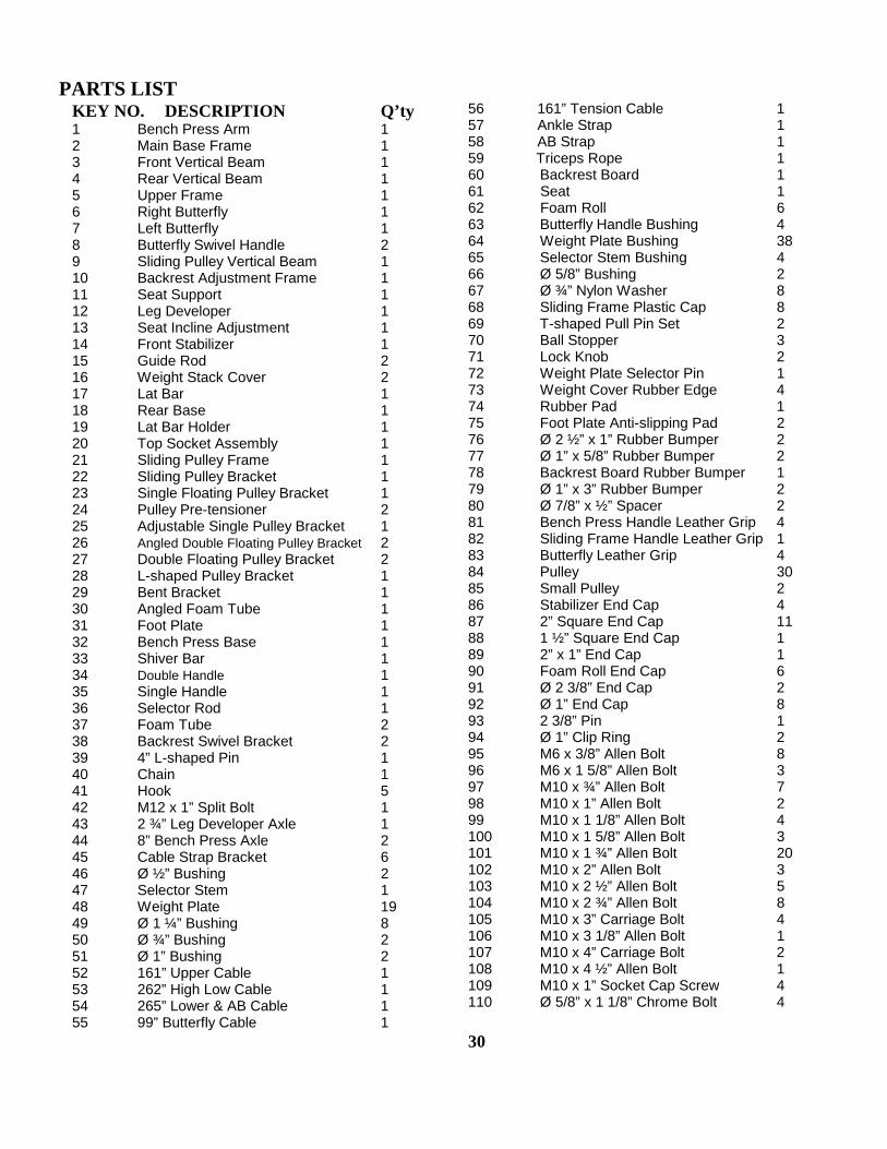
PARTS LIST
KEY NO. DESCRIPTION Q’ty 1 Bench Press Arm 1 2 Main Base Frame 1 3 Front Vertical Beam 1 4 Rear Vertical Beam 1 5 Upper Frame 1 6 Right Butterfly 1 7 Left Butterfly 1 8 Butterfly Swivel Handle 2 9 Sliding Pulley Vertical Beam 1 10 Backrest Adjustment Frame 1 11 Seat Support 1 12 Leg Developer 1 13 Seat Incline Adjustment 1 14 Front Stabilizer 1 15 Guide Rod 2 16 Weight Stack Cover 2 17 Lat Bar 1 18 Rear Base 1 19 Lat Bar Holder 1 20 Top Socket Assembly 1 21 Sliding Pulley Frame 1 22 Sliding Pulley Bracket 1 23 Single Floating Pulley Bracket 1 24 Pulley Pre-tensioner 2 25 Adjustable Single Pulley Bracket 1 26 Angled Double Floating Pulley Bracket 2 27 Double Floating Pulley Bracket 2 28 L-shaped Pulley Bracket 1 29 Bent Bracket 1 30 Angled Foam Tube 1 31 Foot Plate 1 32 Bench Press Base 1 33 Shiver Bar 1 34 Double Handle 1 35 Single Handle 1 36 Selector Rod 1 37 Foam Tube 2 38 Backrest Swivel Bracket 2 39 4” L-shaped Pin 1 40 Chain 1 41 Hook 5 42 M12 x 1” Split Bolt 1 43 2 ¾” Leg Developer Axle 1 44 8” Bench Press Axle 2 45 Cable Strap Bracket 6 46 Ø ½” Bushing 2 47 Selector Stem 1 48 Weight Plate 19 49 Ø 1 ¼” Bushing 8 50 Ø ¾” Bushing 2 51 Ø 1” Bushing 2 52 161” Upper Cable 1 53 262” High Low Cable 1 54 265” Lower & AB Cable 1 55 99” Butterfly Cable 1
56 161” Tension Cable 1 57 Ankle Strap 1 58 AB Strap 1 59 Triceps Rope 1 60 Backrest Board 1 61 Seat 1 62 Foam Roll 6 63 Butterfly Handle Bushing 4 64 Weight Plate Bushing 38 65 Selector Stem Bushing 4 66 Ø 5/8” Bushing 2 67 Ø ¾” Nylon Washer 8 68 Sliding Frame Plastic Cap 8 69 T-shaped Pull Pin Set 2 70 Ball Stopper 3 71 Lock Knob 2 72 Weight Plate Selector Pin 1 73 Weight Cover Rubber Edge 4 74 Rubber Pad 1 75 Foot Plate Anti-slipping Pad 2 76 Ø 2 ½” x 1” Rubber Bumper 2 77 Ø 1” x 5/8” Rubber Bumper 2 78 Backrest Board Rubber Bumper 1 79 Ø 1” x 3” Rubber Bumper 2 80 Ø 7/8” x ½” Spacer 2 81 Bench Press Handle Leather Grip 4 82 Sliding Frame Handle Leather Grip 1 83 Butterfly Leather Grip 4 84 Pulley 30 85 Small Pulley 2 86 Stabilizer End Cap 4 87 2” Square End Cap 11 88 1 ½” Square End Cap 1 89 2” x 1” End Cap 1 90 Foam Roll End Cap 6 91 Ø 2 3/8” End Cap 2 92 Ø 1” End Cap 8 93 2 3/8” Pin 1 94 Ø 1” Clip Ring 2 95 M6 x 3/8” Allen Bolt 8 96 M6 x 1 5/8” Allen Bolt 3 97 M10 x ¾” Allen Bolt 7 98 M10 x 1” Allen Bolt 2 99 M10 x 1 1/8” Allen Bolt 4 100 M10 x 1 5/8” Allen Bolt 3 101 M10 x 1 ¾” Allen Bolt 20 102 M10 x 2” Allen Bolt 3 103 M10 x 2 ½” Allen Bolt 5 104 M10 x 2 ¾” Allen Bolt 8 105 M10 x 3” Carriage Bolt 4 106 M10 x 3 1/8” Allen Bolt 1 107 M10 x 4” Carriage Bolt 2 108 M10 x 4 ½” Allen Bolt 1 109 M10 x 1” Socket Cap Screw 4 110 Ø 5/8” x 1 1/8” Chrome Bolt 4 30
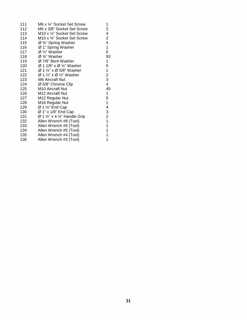
111 M6 x ¼” Socket Set Screw 1 112 M6 x 3/8” Socket Set Screw 2 113 M10 x ½” Socket Set Screw 4 114 M10 x ¾” Socket Set Screw 2 115 Ø ¾” Spring Washer 4 116 Ø 1” Spring Washer 1 117 Ø ½” Washer 6 118 Ø ¾” Washer 93 119 Ø 7/8” Bent Washer 1 120 Ø 1 1/8” x Ø ½” Washer 5 121 Ø 1 ¼” x Ø 5/8” Washer 1 122 Ø 1 ½” x Ø ½” Washer 2 123 M6 Aircraft Nut 3 124 Ø 5/8” Chrome Clip 4 125 M10 Aircraft Nut 45 126 M12 Aircraft Nut 1 127 M12 Regular Nut 5 128 M16 Regular Nut 1 129 Ø 1 ¼” End Cap 4 130 Ø 1” x 1/8” End Cap 3 131 Ø 1 ¼” x 4 ½” Handle Grip 2 132 Allen Wrench #8 (Tool) 1 133 Allen Wrench #6 (Tool) 1 134 Allen Wrench #5 (Tool) 1 135 Allen Wrench #4 (Tool) 1 136 Allen Wrench #3 (Tool) 1
31

IVK-5500 WEIGHT RESISTANCE CHART
* Numbers are approximate. Actual weights may vary. * Values for Butterfly are for each arm.
32
WEIGHT PLATE
Station 1 2 3 4 5 6 7 8 9
Arm Curl 18 29 40 51 62 73 84 95 106
Lat Pull 18 29 40 51 62 73 84 95 106
AB Station 15 26 37 48 59 70 81 92 103
Leg Developer 25 40 55 70 85 100 115 130 145
Bench Press 22 33 44 55 66 77 88 99 110
Butterfly 6 11 16 21 26 31 36 41 46
High Low Cable 8 14 20 26 32 38 44 50 56
WEIGHT PLATE
Station 10 11 12 13 14 15 16 17 18 19
Arm Curl 117 128 139 150 161 172 183 194 205 216
Lat Pull 117 128 139 150 161 172 183 194 205 216
AB Station 114 125 136 147 158 169 180 191 202 213
Leg Developer 160 175 190 205 220 235 250 265 280 295
Bench Press 121 132 143 154 165 176 187 198 209 220
Butterfly 51 56 61 66 71 76 81 86 91 96
High Low Cable 62 68 74 80 86 92 98 104 110 116
IVANKO By IMPEX FITNESS PRODUCTS
LIMITED WARRANTY
IMPEX Inc. ("IMPEX") warrants this product to be free from defects in workmanship and material, under normal use and service conditions, for a period of two years on the Frame from the date of purchase. This warranty extends only to the original purchaser. IMPEX's obligation under this Warranty is limited to replacing or repairing, at IMPEX's option. All returns must be pre-authorized by IMPEX. Pre-authorization may be obtained by calling IMPEX Customer Service Department at 1-800-999-8899. All freights on products returned to IMPEX must be prepaid by the customer. This warranty does not extend to any product or damage to a product caused by or attributable to freight damage, abuse, misuse, improper or abnormal usage or repairs not provided by an IMPEX authorized service center or for products used for commercial or rental purposes. No other warranty beyond that specifically set forth above is authorized by IMPEX. IMPEX is not responsible or liable for indirect, special or consequential damages arising out of or in connection with the use or performance of the product or other damages with respect to any economic loss, loss of property, loss of revenues or profits, loss of enjoyments or use, costs of removal, installation or other consequential damages or whatsoever natures. Some states do not allow the exclusion or limitation of incidental or consequential damages. Accordingly, the above limitation may not apply to you. The warranty extended hereunder is in lieu of any and all other warranties and any implied warranties of merchantability or fitness for a particular purpose is limited in its scope and duration to the terms set forth herein. Some states do not allow limitations on how long an implied warranty lasts. Accordingly, the above limitation may not apply to you. This warranty gives you specific legal right. You may also have other rights which vary from state to state. Register on-line www.impex-fitness.com
IMPEX INC. 14777 Don Julian
City of Industry, CA 91746 ORDERING REPLACEMENT PARTS Replacement parts can be ordered by calling our Customer Service Department toll-free at 1-800-999-8899 during our regular business hours: Monday through Friday, 9 am until 5 pm Pacific standard time. [email protected] When ordering replacement parts, always give the following information. 1. Model 2. Description of Parts 3. Part Number 4. Date of Purchase
33
Recommended