Introduction to IP Multicast Routing
by Chuck Semeria and Tom Maufer
AbstractThe first part of this paper describes the benefits of multicasting, the Multicast Backbone(MBONE), Class D addressing, and the operation of the Internet Group ManagementProtocol (IGMP). The second section explores a number of different algorithms thatmay potentially be employed by multicast routing protocols:
- Flooding- Spanning Trees- Reverse Path Broadcasting (RPB)- Truncated Reverse Path Broadcasting (TRPB)- Reverse Path Multicasting (RPM)- Core-Based Trees
The third part contains the main body of the paper. It describes how the previousalgorithms are implemented in multicast routing protocols available today.
- Distance Vector Multicast Routing Protocol (DVMRP)- Multicast OSPF (MOSPF)- Protocol-Independent Multicast (PIM)
IntroductionThere are three fundamental types of IPv4 addresses: unicast, broadcast, and multicast.A unicast address is designed to transmit a packet to a single destination. A broadcastaddress is used to send a datagram to an entire subnetwork. A multicast address isdesigned to enable the delivery of datagrams to a set of hosts that have been configuredas members of a multicast group in various scattered subnetworks.
Multicasting is not connection oriented. A multicast datagram is delivered to destinationgroup members with the same “best-effort” reliability as a standard unicast IPdatagram. This means that a multicast datagram is not guaranteed to reach all membersof the group, or arrive in the same order relative to the transmission of other packets.
The only difference between a multicast IP packet and a unicast IP packet is the presenceof a “group address” in the Destination Address field of the IP header. Instead of aClass A, B, or C IP address, multicasting employs a Class D destination address format(224.0.0.0- 239.255.255.255).
Multicast GroupsIndividual hosts are free to join or leave a multicast group at any time. There are norestrictions on the physical location or the number of members in a multicast group. A
host may be a member of more than one multicast group at any given time and does nothave to belong to a group to send messages to members of a group.
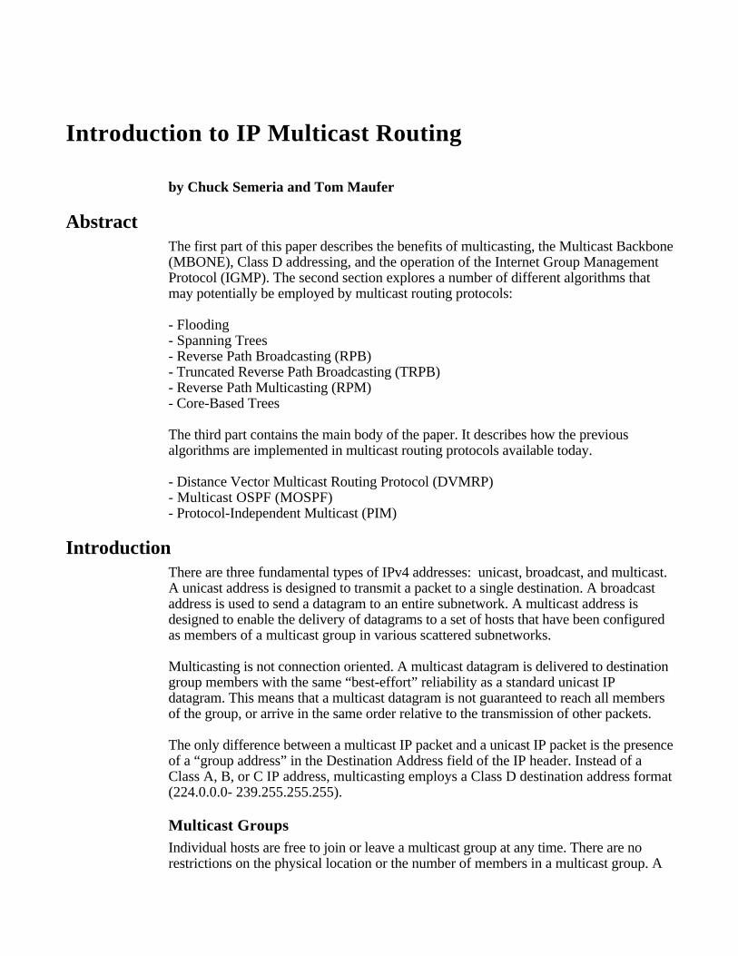
Group Membership ProtocolA group membership protocol is employed by routers to learn about the presence ofgroup members on their directly attached subnetworks. When a host joins a multicastgroup, it transmits a group membership protocol message for the group(s) that it wishesto receive, and sets its IP process and network interface card to receive frames addressedto the multicast group. This receiver-initiated join process has excellent scalingproperties since, as the multicast group increases in size, it becomes ever more likelythat a new group member will be able to locate a nearby branch of the multicastdistribution tree.
Router
Router Router
Multicast Routing ProtocolGroup Membership Protocol
Figure 1: Multicast IP Delivery Service
Multicast Routing ProtocolMulticast routers execute a multicast routing protocol to define delivery paths that enablethe forwarding of multicast datagrams across an internetwork. The Distance VectorMulticast Routing Protocol (DVMRP) is a distance-vector routing protocol, andMulticast OSPF (MOSPF) is an extension to the OSPF link-state unicast routingprotocol.
Multicast Support for Emerging Internet ApplicationsToday, the majority of Internet applications rely on point-to-point transmission. Theutilization of point-to-multipoint transmission has traditionally been limited to local areanetwork applications. Over the past few years the Internet has seen a rise in the numberof new applications that rely on multicast transmission. Multicast IP conservesbandwidth by forcing the network to do packet replication only when necessary, andoffers an attractive alternative to unicast transmission for the delivery of network tickertapes, live stock quotes, multiparty video-conferencing, and shared whiteboardapplications (among others). It is important to note that the applications for IP Multicast
are not solely limited to the Internet. Multicast IP can also play an important role in largedistributed commercial networks.
Reducing Network LoadAssume that a stock ticker application is required to transmit packets to 100 stationswithin an organization’s network. Unicast transmission to the group of stations willrequire the periodic transmission of 100 packets where many packets may be required totraverse the same link(s). Multicast transmission is the ideal solution for this type ofapplication since it requires only a single packet transmission by the source which isthen replicated at forks in the multicast delivery tree.
Broadcast transmission is not an effective solution for this type of application since itaffects the CPU performance of each and every end station that sees the packet and itwastes bandwidth.
Resource DiscoverySome applications implement multicast group addresses instead of broadcasts totransmit packets to group members residing on the same network. However, there is noreason to limit the extent of a multicast transmission to a single LAN. The time-to-live(TTL) field in the IP header can be used to limit the range (or “scope”) of a multicasttransmission.
Support for Datacasting ApplicationsSince 1992 the Internet Engineering Task Force (IETF) has conducted a series of“audiocast” experiments in which live audio and video were multicast from the IETFmeeting site to destinations around the world. Datacasting takes compressed audio andvideo signals from the source station and transmits them as a sequence of UDP packetsto a group address. Multicasting might eliminate an organization’s need to maintainparallel networks for voice, video, and data.
The Internet’s Multicast Backbone (MBONE)The Internet Multicast Backbone (MBONE) is an interconnected set of subnetworks androuters that support the delivery of IP multicast traffic. The goal of the MBONE is toconstruct a semipermanent IP multicast testbed to enable the deployment of multicastapplications without waiting for the ubiquitous deployment of multicast-capable routersin the Internet.
The MBONE has grown from 40 subnets in four different countries in 1992 to morethan 2800 subnets in over 25 countries by April 1996. With new multicast applicationsand multicast-based services appearing, it appears likely that the use of multicasttechnology in the Internet will continue to grow at an ever-increasing rate.
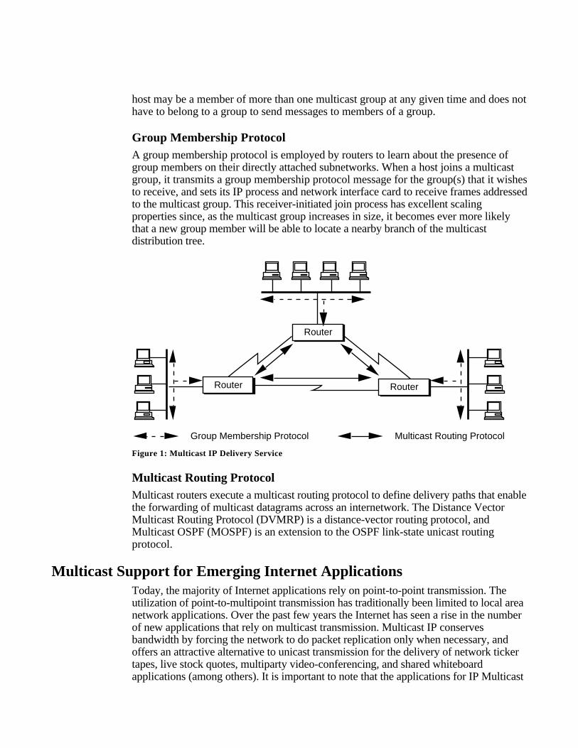
The MBONE is a virtual network that is layered on top of sections of the physicalInternet. It is composed of islands of multicast routing capability connected to otherislands by virtual point-to-point links called “tunnels.” The tunnels allow multicasttraffic to pass through the non-multicast-capable parts of the Internet. IP multicast
packets are encapsulated as IP-over-IP (i.e., the protocol number is set to 4), so theylook like normal unicast packets to intervening routers. The encapsulation is added onentry to a tunnel and stripped off on exit from a tunnel. This set of multicast routers,their directly connected subnetworks, and the interconnecting tunnels define theMBONE.
tunnel
tunnel tunnel
tunnel
IslandB
IslandD
IslandC
IslandA
IslandE
Figure 2: Internet Multicast Backbone (MBONE)
Since the MBONE and the Internet have different topologies, multicast routers execute aseparate routing protocol to decide how to forward multicast packets. The majority ofthe MBONE routers currently use the Distance Vector Multicast Routing Protocol(DVMRP), although some portions of the MBONE execute either Multicast OSPF(MOSPF) or the Protocol-Independent Multicast (PIM) routing protocols. The operationof each of these protocols is discussed later in this paper.
The MBONE carries audio and video multicasts of IETF meetings, NASA spaceshuttle missions, U.S. House and Senate sessions, and live satellite weather photos. TheSession Directory (SD) tool provides users with a listing of the active multicast sessionson the MBONE and allows them to define or join a conference.
Multicast AddressingA multicast address is assigned to a set of receivers defining a multicast group. Sendersuse the multicast address as the destination IP address of a packet that is to betransmitted to all group members.
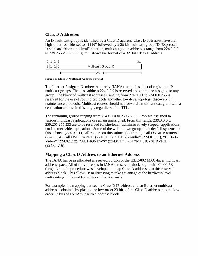
Class D AddressesAn IP multicast group is identified by a Class D address. Class D addresses have theirhigh-order four bits set to “1110” followed by a 28-bit multicast group ID. Expressedin standard “dotted-decimal” notation, multicast group addresses range from 224.0.0.0to 239.255.255.255. Figure 3 shows the format of a 32- bit Class D address.
0 2 3 311
1 1 1 0 Multicast Group ID
28 bits
Figure 3: Class D Multicast Address Format
The Internet Assigned Numbers Authority (IANA) maintains a list of registered IPmulticast groups. The base address 224.0.0.0 is reserved and cannot be assigned to anygroup. The block of multicast addresses ranging from 224.0.0.1 to 224.0.0.255 isreserved for the use of routing protocols and other low-level topology discovery ormaintenance protocols. Multicast routers should not forward a multicast datagram with adestination address in this range, regardless of its TTL.
The remaining groups ranging from 224.0.1.0 to 239.255.255.255 are assigned tovarious multicast applications or remain unassigned. From this range, 239.0.0.0 to239.255.255.255 are to be reserved for site-local “administratively scoped” applications,not Internet-wide applications. Some of the well-known groups include: “all systems onthis subnet” (224.0.0.1), “all routers on this subnet”(224.0.0.2), “all DVMRP routers”(224.0.0.4), “all OSPF routers” (224.0.0.5), “IETF-1-Audio” (224.0.1.11), “IETF-1-Video” (224.0.1.12), “AUDIONEWS” (224.0.1.7), and “MUSIC- SERVICE”(224.0.1.16).
Mapping a Class D Address to an Ethernet AddressThe IANA has been allocated a reserved portion of the IEEE-802 MAC-layer multicastaddress space. All of the addresses in IANA’s reserved block begin with 01-00-5E(hex). A simple procedure was developed to map Class D addresses to this reservedaddress block. This allows IP multicasting to take advantage of the hardware-levelmulticasting supported by network interface cards.
For example, the mapping between a Class D IP address and an Ethernet multicastaddress is obtained by placing the low-order 23 bits of the Class D address into the low-order 23 bits of IANA’s reserved address block.
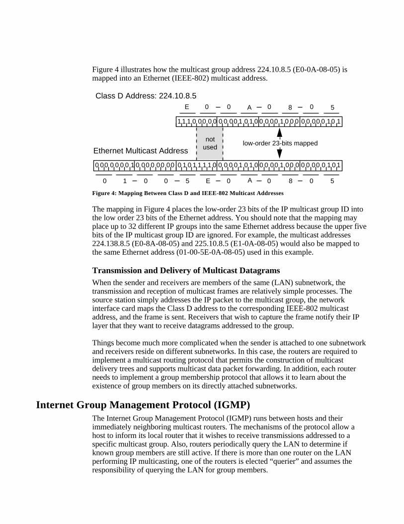
Figure 4 illustrates how the multicast group address 224.10.8.5 (E0-0A-08-05) ismapped into an Ethernet (IEEE-802) multicast address.
Class D Address: 224.10.8.5
Ethernet Multicast Address
1 01 1 00 0 0 0 0 00 1 0 1 0 0 0 00 1 0 0 0 0 0 00 0 10 1
0 0 0 0 0 1 0 0 00 00 0 0 0 00 0 00 00 0 0 0 0 1 0 00 0 00 00 0 1 0 1 1 1 1 0 1 0 1 1 1
notused
0 1 0 0 5 E 0 A 0 8 0 5
low-order 23-bits mapped
0 A 0 8 0 5E 0
Figure 4: Mapping Between Class D and IEEE-802 Multicast Addresses
The mapping in Figure 4 places the low-order 23 bits of the IP multicast group ID intothe low order 23 bits of the Ethernet address. You should note that the mapping mayplace up to 32 different IP groups into the same Ethernet address because the upper fivebits of the IP multicast group ID are ignored. For example, the multicast addresses224.138.8.5 (E0-8A-08-05) and 225.10.8.5 (E1-0A-08-05) would also be mapped tothe same Ethernet address (01-00-5E-0A-08-05) used in this example.
Transmission and Delivery of Multicast DatagramsWhen the sender and receivers are members of the same (LAN) subnetwork, thetransmission and reception of multicast frames are relatively simple processes. Thesource station simply addresses the IP packet to the multicast group, the networkinterface card maps the Class D address to the corresponding IEEE-802 multicastaddress, and the frame is sent. Receivers that wish to capture the frame notify their IPlayer that they want to receive datagrams addressed to the group.
Things become much more complicated when the sender is attached to one subnetworkand receivers reside on different subnetworks. In this case, the routers are required toimplement a multicast routing protocol that permits the construction of multicastdelivery trees and supports multicast data packet forwarding. In addition, each routerneeds to implement a group membership protocol that allows it to learn about theexistence of group members on its directly attached subnetworks.
Internet Group Management Protocol (IGMP)The Internet Group Management Protocol (IGMP) runs between hosts and theirimmediately neighboring multicast routers. The mechanisms of the protocol allow ahost to inform its local router that it wishes to receive transmissions addressed to aspecific multicast group. Also, routers periodically query the LAN to determine ifknown group members are still active. If there is more than one router on the LANperforming IP multicasting, one of the routers is elected “querier” and assumes theresponsibility of querying the LAN for group members.
Based on the group membership information learned from the IGMP, a router is able todetermine which (if any) multicast traffic needs to be forwarded to each of its “leaf”subnetworks. Multicast routers use this information, in conjunction with a multicastrouting protocol, to support IP multicasting across the Internet.
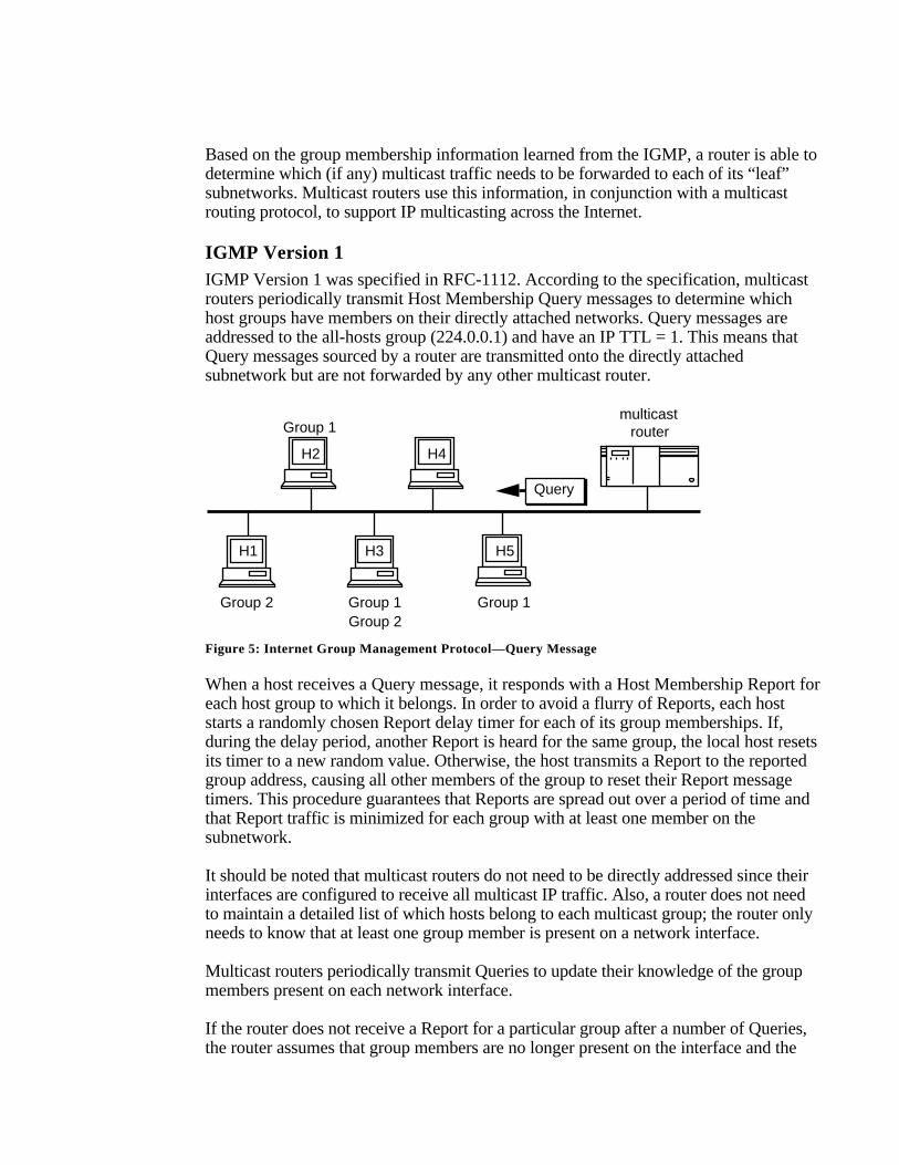
IGMP Version 1IGMP Version 1 was specified in RFC-1112. According to the specification, multicastrouters periodically transmit Host Membership Query messages to determine whichhost groups have members on their directly attached networks. Query messages areaddressed to the all-hosts group (224.0.0.1) and have an IP TTL = 1. This means thatQuery messages sourced by a router are transmitted onto the directly attachedsubnetwork but are not forwarded by any other multicast router.
Group 1
Group 1Group 2 Group 1Group 2
Query
multicastrouter
H2 H4
H1 H3 H5
Figure 5: Internet Group Management Protocol—Query Message
When a host receives a Query message, it responds with a Host Membership Report foreach host group to which it belongs. In order to avoid a flurry of Reports, each hoststarts a randomly chosen Report delay timer for each of its group memberships. If,during the delay period, another Report is heard for the same group, the local host resetsits timer to a new random value. Otherwise, the host transmits a Report to the reportedgroup address, causing all other members of the group to reset their Report messagetimers. This procedure guarantees that Reports are spread out over a period of time andthat Report traffic is minimized for each group with at least one member on thesubnetwork.
It should be noted that multicast routers do not need to be directly addressed since theirinterfaces are configured to receive all multicast IP traffic. Also, a router does not needto maintain a detailed list of which hosts belong to each multicast group; the router onlyneeds to know that at least one group member is present on a network interface.
Multicast routers periodically transmit Queries to update their knowledge of the groupmembers present on each network interface.
If the router does not receive a Report for a particular group after a number of Queries,the router assumes that group members are no longer present on the interface and the
group is removed from the list of group memberships for the directly attachedsubnetwork.
When a host first joins a group, it immediately transmits a Report for the group ratherthan waiting for a router Query. This guarantees that the host will receive trafficaddressed to the group if it is the first member of that group on the subnetwork.
IGMP Version 2IGMP Version 2 was distributed as part of the IP Multicasting (Version 3.3 throughVersion 3.8) code package. Initially, there was no detailed specification for IGMPVersion 2 other than the source code. However, the complete specification has recentlybeen published in <draft-ietf-idmr-igmp-v2-01.txt>, which will replace the informalspecification contained in Appendix I of RFC-1112. IGMP Version 2 enhances andextends IGMP Version 1 while also providing backward compatibility with Version 1hosts.
IGMP Version 2 defines a procedure for the election of the multicast querier for eachLAN. In IGMP Version 2, the router with the lowest IP address on the LAN is electedthe multicast querier. In IGMP Version 1, the querier election was determined by themulticast routing protocol. This could lead to potential problems because each multicastrouting protocol used different methods for determining the multicast querier.
IGMP Version 2 defines a new type of Query message—the Group-Specific Querymessage. Group-Specific Query messages allow a router to transmit a Query to aspecific multicast group rather than all groups residing on a directly attachedsubnetwork.
Finally, IGMP Version 2 defines a Leave Group message to lower IGMP’s “leavelatency.” When the last host to respond to a Query with a Report wishes to leave thatspecific group, the host transmits a Leave Group message to the all-routers group(224.0.0.2) with the group field set to the group to be left. In response to a Leave Groupmessage, the router begins the transmission of Group-Specific Query messages on theinterface that received the Leave Group message. If there are no Reports in response tothe Group-Specific Query messages, the group is removed from the list of groupmemberships for the directly attached subnetwork.
IGMP Version 3IGMP Version 3 is a preliminary draft specification published in <draft-cain-igmp-00.txt>. IGMP Version 3 introduces support for Group-Source Report messages so thata host can elect to receive traffic from specific sources of a multicast group. AnInclusion Group-Source Report message allows a host to specify the IP addresses of thespecific sources it wants to receive. An Exclusion Group-Source Report message allowsa host to explicitly identify the sources that it does not want to receive. With IGMPVersion 1 and Version 2, if a host wants to receive any sources from a group, the trafficfrom all sources for the group has to be forwarded onto the subnetwork.
IGMP Version 3 will help conserve bandwidth by allowing a host to select the specificsources from which it wants to receive traffic. Also, multicast routing protocols will be
able to make use of this information to conserve bandwidth when constructing thebranches of their multicast delivery trees.
Finally, support for Leave Group messages first introduced in IGMP Version 2 hasbeen enhanced to support Group-Source Leave messages. This feature allows a host toleave an entire group or to specify the specific IP address(es) of the (source, group)pair(s) that it wishes to leave.
Multicast Forwarding AlgorithmsIGMP provides the final step in a multicast packet delivery service since it is onlyconcerned with the forwarding of multicast traffic from the local router to groupmembers on directly attached subnetworks. IGMP is not concerned with the delivery ofmulticast packets between neighboring routers or across an internetwork.To provide an Internet-wide delivery service, it is necessary to define multicast routingprotocols. A multicast routing protocol is responsible for the construction of multicastpacket delivery trees and performing multicast packet forwarding. This section exploresa number of different algorithms that may potentially be employed by multicast routingprotocols:
- Flooding- Spanning Trees- Reverse Path Broadcasting (RPB)- Truncated Reverse Path Broadcasting (TRPB)- Reverse Path Multicasting (RPM)- Core-Based Trees
Later sections will describe how these algorithms are implemented in the most prevalentmulticast routing protocols in the Internet today.
- Distance Vector Multicast Routing Protocol (DVMRP)- Multicast OSPF (MOSPF)- Protocol-Independent Multicast (PIM)
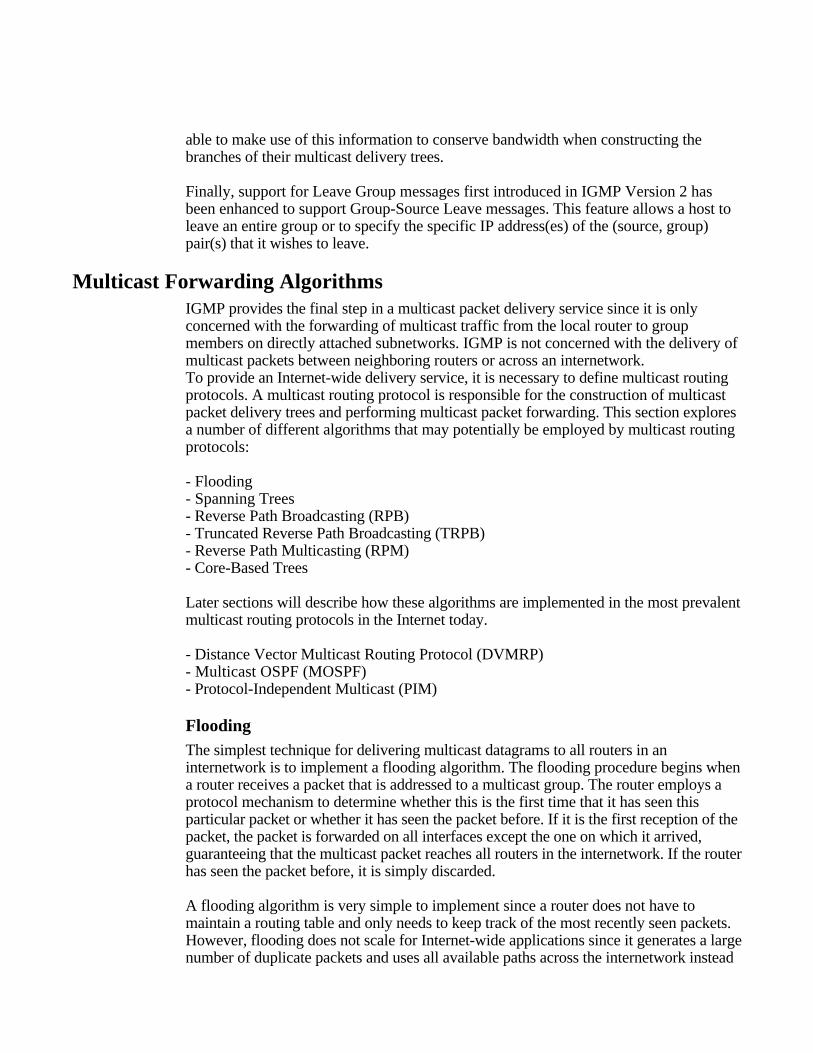
FloodingThe simplest technique for delivering multicast datagrams to all routers in aninternetwork is to implement a flooding algorithm. The flooding procedure begins whena router receives a packet that is addressed to a multicast group. The router employs aprotocol mechanism to determine whether this is the first time that it has seen thisparticular packet or whether it has seen the packet before. If it is the first reception of thepacket, the packet is forwarded on all interfaces except the one on which it arrived,guaranteeing that the multicast packet reaches all routers in the internetwork. If the routerhas seen the packet before, it is simply discarded.
A flooding algorithm is very simple to implement since a router does not have tomaintain a routing table and only needs to keep track of the most recently seen packets.However, flooding does not scale for Internet-wide applications since it generates a largenumber of duplicate packets and uses all available paths across the internetwork instead
of just a limited number. Also, the flooding algorithm makes inefficient use of routermemory resources since each router is required to maintain a distinct table entry for eachrecently seen packet.
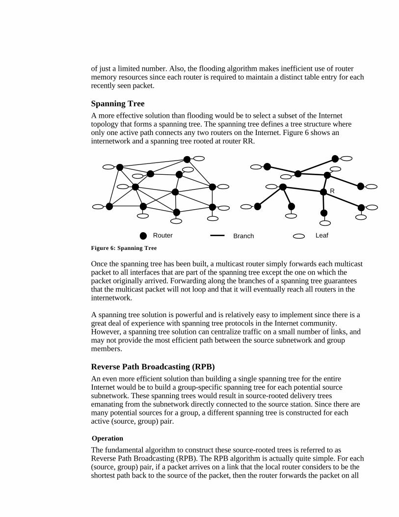
Spanning TreeA more effective solution than flooding would be to select a subset of the Internettopology that forms a spanning tree. The spanning tree defines a tree structure whereonly one active path connects any two routers on the Internet. Figure 6 shows aninternetwork and a spanning tree rooted at router RR.
Router Leaf
R
Branch
Figure 6: Spanning Tree
Once the spanning tree has been built, a multicast router simply forwards each multicastpacket to all interfaces that are part of the spanning tree except the one on which thepacket originally arrived. Forwarding along the branches of a spanning tree guaranteesthat the multicast packet will not loop and that it will eventually reach all routers in theinternetwork.
A spanning tree solution is powerful and is relatively easy to implement since there is agreat deal of experience with spanning tree protocols in the Internet community.However, a spanning tree solution can centralize traffic on a small number of links, andmay not provide the most efficient path between the source subnetwork and groupmembers.
Reverse Path Broadcasting (RPB)An even more efficient solution than building a single spanning tree for the entireInternet would be to build a group-specific spanning tree for each potential sourcesubnetwork. These spanning trees would result in source-rooted delivery treesemanating from the subnetwork directly connected to the source station. Since there aremany potential sources for a group, a different spanning tree is constructed for eachactive (source, group) pair.
Operation
The fundamental algorithm to construct these source-rooted trees is referred to asReverse Path Broadcasting (RPB). The RPB algorithm is actually quite simple. For each(source, group) pair, if a packet arrives on a link that the local router considers to be theshortest path back to the source of the packet, then the router forwards the packet on all
interfaces except the incoming interface. Otherwise, the packet is discarded. Theinterface over which the router expects to receive multicast packets from a particularsource is referred to as the “parent” link. The outbound links over which the routerforwards the multicast packet are called the “child” links.
Routerl
Source
"parent” link
!2
!1 !3 "child"child
shortest path back to the
Figure 7: Reverse Path Broadcasting—Forwarding Algorithm
This basic algorithm can be enhanced to reduce unnecessary packet duplication if therouter making the forwarding decision can determine whether a neighboring router on apotential child link considers the local router to be on its shortest path back to the source[i.e., on the remote router’s parent link for the (source, group) pair]. If this is the case,the packet is forwarded to the neighbor. Otherwise, the datagram is not forwarded on thepotential child link because the neighboring router will be required to discard the packetsince it arrives on a non-parent link for the (source, group) pair.
The information needed to make this “downstream” decision is relatively easy to derivefrom a link-state routing protocol since each router maintains a topological database forthe entire routing domain. If a distance-vector routing protocol is employed, a neighborcan either advertise its previous hop for the (source, group) pair as part of its routingupdate messages or “poison reverse” the route. Either of these techniques allows anupstream router to determine if a downstream neighboring router considers it to be onthe downstream router’s shortest path back to the source.
Router
Leaf
1 2
3
4 5 6 7
8 9
A
B C
D
E
F
Branch
S
Shortest-path
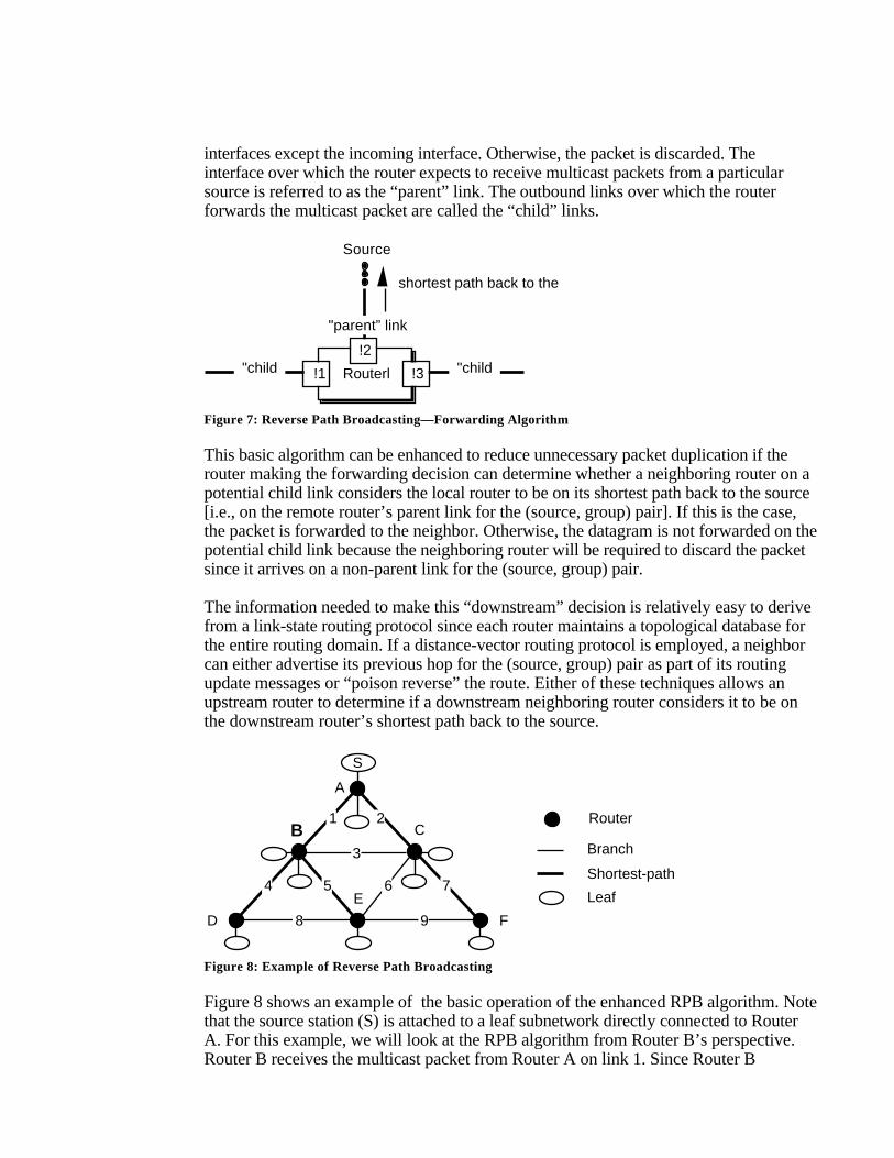
Figure 8: Example of Reverse Path Broadcasting
Figure 8 shows an example of the basic operation of the enhanced RPB algorithm. Notethat the source station (S) is attached to a leaf subnetwork directly connected to RouterA. For this example, we will look at the RPB algorithm from Router B’s perspective.Router B receives the multicast packet from Router A on link 1. Since Router B
considers link 1 to be the parent link for the (source, group) pair, it forwards the packeton link 4, link 5, and the local leaf subnetworks if they have group members. Router Bdoes not forward the packet on link 3 because it knows from routing protocol exchangesthat Router C considers link 2 as its parent link for the (source, group) pair. If Router Bwere to forward the packet on link 3 it would be discarded by Router C since it wouldarrive on a non-parent link for the (source, group) pair.
Benefits and Limitations
The key benefit to reverse path broadcasting is that it is reasonably efficient and easy toimplement. It does not require that the router know about the entire spanning tree nordoes it require a special mechanism to stop the forwarding process, as flooding does. Inaddition, it guarantees efficient delivery since multicast packets always follow the“shortest” path from the source station to the destination group. Finally, the packets aredistributed over multiple links, resulting in better network utilization since a different treeis computed for each (source, group) pair.
One of the major limitations of the RPB algorithm is that it does not take into accountmulticast group membership when building the distribution tree for a (source, group)pair. As a result, datagrams may be unnecessarily forwarded to subnetworks that haveno members in the destination group.
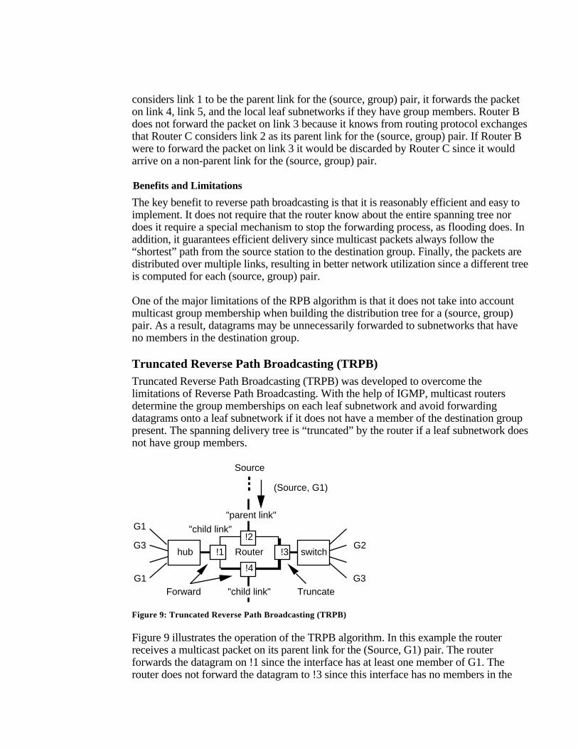
Truncated Reverse Path Broadcasting (TRPB)Truncated Reverse Path Broadcasting (TRPB) was developed to overcome thelimitations of Reverse Path Broadcasting. With the help of IGMP, multicast routersdetermine the group memberships on each leaf subnetwork and avoid forwardingdatagrams onto a leaf subnetwork if it does not have a member of the destination grouppresent. The spanning delivery tree is “truncated” by the router if a leaf subnetwork doesnot have group members.
Routerhub switch
"parent link"
!2
!1 !3
G1
G1
G2
Source
Forward Truncate
(Source, G1)
"child link"
G3
G3!4
"child link"
Figure 9: Truncated Reverse Path Broadcasting (TRPB)
Figure 9 illustrates the operation of the TRPB algorithm. In this example the routerreceives a multicast packet on its parent link for the (Source, G1) pair. The routerforwards the datagram on !1 since the interface has at least one member of G1. Therouter does not forward the datagram to !3 since this interface has no members in the
destination group. The datagram is forwarded on !4 if and only if a downstream routerconsiders the interface as part of its parent link for the (Source, G1) pair.
TRPB removes some limitations of RPB, but it solves only part of the problem. Iteliminates unnecessary traffic on leaf subnetworks but it does not consider groupmemberships when building the branches of the distribution tree.
Reverse Path Multicasting (RPM)Reverse Path Multicasting (RPM) is an enhancement to Reverse Path Broadcasting andTruncated Reverse Path Broadcasting. RPM creates a delivery tree that spans only:
-Subnetworks with group members, and-Routers and subnetworks along the shortest path to subnetworks with group members
RPM allows the source-rooted spanning tree to be pruned so that datagrams are onlyforwarded along branches that lead to members of the destination group.
Operation
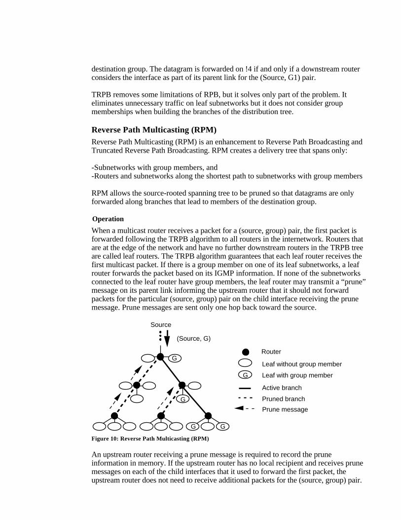
When a multicast router receives a packet for a (source, group) pair, the first packet isforwarded following the TRPB algorithm to all routers in the internetwork. Routers thatare at the edge of the network and have no further downstream routers in the TRPB treeare called leaf routers. The TRPB algorithm guarantees that each leaf router receives thefirst multicast packet. If there is a group member on one of its leaf subnetworks, a leafrouter forwards the packet based on its IGMP information. If none of the subnetworksconnected to the leaf router have group members, the leaf router may transmit a “prune”message on its parent link informing the upstream router that it should not forwardpackets for the particular (source, group) pair on the child interface receiving the prunemessage. Prune messages are sent only one hop back toward the source.
Source
(Source, G)
Router
Leaf without group member
Active branch
Leaf with group memberG
G
G
Pruned branch
G
G
Prune message
Figure 10: Reverse Path Multicasting (RPM)
An upstream router receiving a prune message is required to record the pruneinformation in memory. If the upstream router has no local recipient and receives prunemessages on each of the child interfaces that it used to forward the first packet, theupstream router does not need to receive additional packets for the (source, group) pair.
This means that the upstream router can generate a prune message of its own, one hopback toward the source. This succession of prune messages creates a multicastforwarding tree that contains only “live” branches (i.e., branches that lead to activegroup members).
Since both the group membership and network topology are dynamically changing, thepruned state of the multicast forwarding tree must be refreshed at regular intervals.Periodically, the prune information is removed from the memory of all routers and thenext packet for the (source, group) pair is forwarded to all leaf routers. This results in anew burst of prune messages, allowing the multicast forwarding tree to adapt to theever-changing multicast delivery requirements of the internetwork.
Limitations
Despite the improvements offered by the RPM algorithm, there are still several scalingissues that need to be addressed when attempting to develop an Internet-wide deliveryservice. The first limitation is that multicast packets must be periodically forwarded toevery router in the internetwork. The second drawback is that each router is required tomaintain state information for all groups and each source. The significance of theseshortcomings is amplified as the number of sources and groups in the multicastinternetwork expands.
Core-Based Trees (CBT)The latest addition to the existing set of multicast forwarding algorithms is Core BasedTrees (CBT). Unlike existing algorithms which build a source-rooted, shortest-path treefor each (source, group) pair, CBT constructs a single delivery tree that is shared by allmembers of a group. The CBT algorithm is quite similar to the spanning tree algorithmexcept it allows a different core-based tree for each group. Multicast traffic for eachgroup is sent and received over the same delivery tree, regardless of the source.
Operation
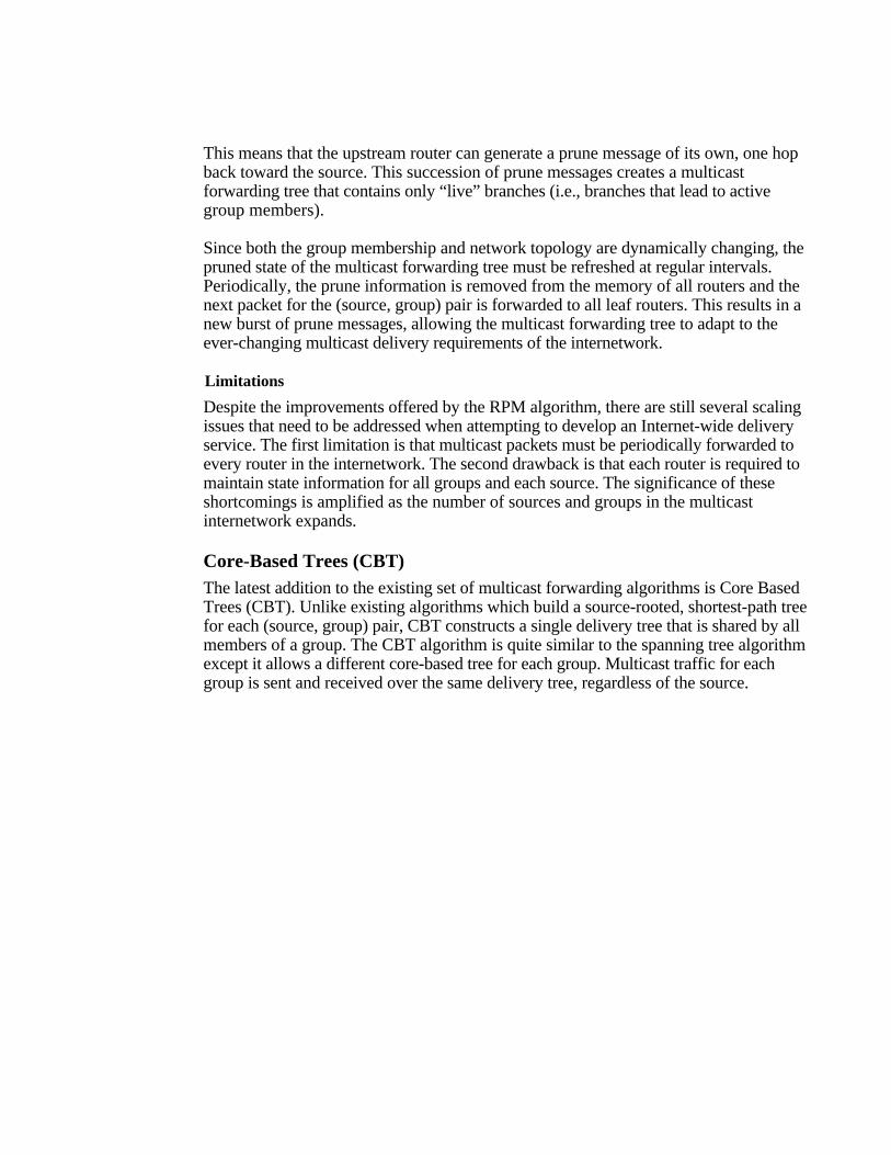
A core-based tree may involve a single router or set of routers, which acts as the core ofa multicast delivery tree. Figure 11 illustrates how multicast traffic is forwarded across aCBT “backbone” to all members of the group. Note that the CBT backbone may containboth core and non-core routers.
Core router
Non-core router
CBT backbone
Multicast packet path
Incoming multicast packetfor the group
Figure 11: Multi-Core CBT Multicast Delivery Tree
Each station that wishes to receive traffic that has been addressed to a multicast group isrequired to send a “join” message toward the “core tree” of the particular multicastgroup. A potential group member only needs to know the address of one of the group’score routers in order to transmit a unicast join request. The join request is processed byall intermediate routers that identify the interface on which the join was received asbelonging to the group’s delivery tree. The intermediate routers continue to forward thejoin message toward the core and marking local interfaces until the request reaches acore router.
Similar to other multicast forwarding algorithms, CBT does not require that the sourceof a multicast packet be a member of the destination group. Packets sourced by a non-group member are simply unicast toward the core until they reach the first router that isa member of the group’s delivery tree. When the unicast packet reaches a member of thedelivery tree, the packet is multicast to all outgoing interfaces that are part of the treeexcept the incoming link. This guarantees that the multicast packet is forwarded to allrouters on the delivery tree.
Benefits
In terms of scalability, CBT has several advantages over the Reverse Path Multicasting(RPM) algorithm. CBT makes efficient use of router resources since it only requires arouter to maintain state information for each group, not for each (source, group) pair.Also, CBT conserves network bandwidth since it does not require that multicast framesbe periodically forwarded to all multicast routers in the internetwork.
Limitations
Despite these benefits, there are still several limitations to the CBT approach. CBT mayresult in traffic concentration and bottlenecks near core routers since traffic from all
sources traverses the same set of links as it approaches the core. In addition, a singleshared delivery tree may create suboptimal routes resulting in increased delay—a criticalissue for some multimedia applications. Finally, new algorithms still need to bedeveloped to support core management which encompasses all aspects of core routerselection and (potentially) dynamic placement strategies.
Distance Vector Multicast Routing Protocol (DVMRP)The Distance Vector Multicast Routing Protocol (DVMRP) is a distance-vector routingprotocol designed to support the forwarding of multicast datagrams through aninternetwork. DVMRP constructs source-rooted multicast delivery trees using variantsof the Reverse Path Broadcasting (RPB) algorithm. Some version of DVMRP iscurrently deployed in the majority of MBONE routers.
DVMRP was first defined in RFC-1075. The original specification was derived fromthe Routing Information Protocol (RIP) and employed the Truncated Reverse PathBroadcasting (TRPB) algorithm. The major difference between RIP and DVMRP is thatRIP is concerned with calculating the next hop to a destination, while DVMRP isconcerned with computing the previous hop back to a source. It is important to note thatthe latest mrouted version 3.8 and vendor implementations have extended DVMRP toemploy the Reverse Path Multicasting (RPM) algorithm. This means that the latestimplementations of DVMRP are quite different from the original RFC specification inmany regards.
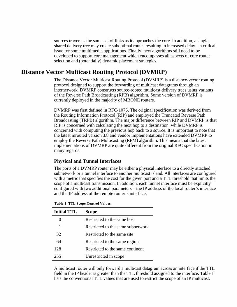
Physical and Tunnel InterfacesThe ports of a DVMRP router may be either a physical interface to a directly attachedsubnetwork or a tunnel interface to another multicast island. All interfaces are configuredwith a metric that specifies the cost for the given port and a TTL threshold that limits thescope of a multicast transmission. In addition, each tunnel interface must be explicitlyconfigured with two additional parameters—the IP address of the local router’s interfaceand the IP address of the remote router’s interface.
Table 1 TTL Scope Control Values
Initial TTL Scope
0 Restricted to the same host
1 Restricted to the same subnetwork
32 Restricted to the same site
64 Restricted to the same region
128 Restricted to the same continent
255 Unrestricted in scope
A multicast router will only forward a multicast datagram across an interface if the TTLfield in the IP header is greater than the TTL threshold assigned to the interface. Table 1lists the conventional TTL values that are used to restrict the scope of an IP multicast.
For example, a multicast datagram with a TTL of less than 32 is restricted to the samesite and should not be forwarded across an interface to other sites in the same region.
Basic OperationDVMRP implements the Reverse Path Multicasting (RPM) algorithm. According toRPM, the first datagram for any (source, group) pair is forwarded across the entireinternetwork, providing that the packet’s TTL and router interface thresholds permit. Theinitial datagram is delivered to all leaf routers, which transmit prune messages backtoward the source if there are no group members on their directly attached leafsubnetworks. The prune messages result in the removal of branches from the tree thatdo not lead to group members, thus creating a source-specific shortest path tree with allleaves having group members. After a period of time, the pruned branches grow backand the next datagram for the (source, group) pair is forwarded across the entireinternetwork, resulting in a new set of prune messages.
DVMRP implements a mechanism to quickly “graft” back a previously pruned branchof a group’s delivery tree. If a router that previously sent a prune message for a (source,group) pair discovers new group members on a leaf network, it sends a graft message tothe group’s previous-hop router. When an upstream router receives a graft message, itcancels out the previously received prune message. Graft messages may cascade backtoward the sourc,e allowing previously pruned branches to be restored as part of themulticast delivery tree.
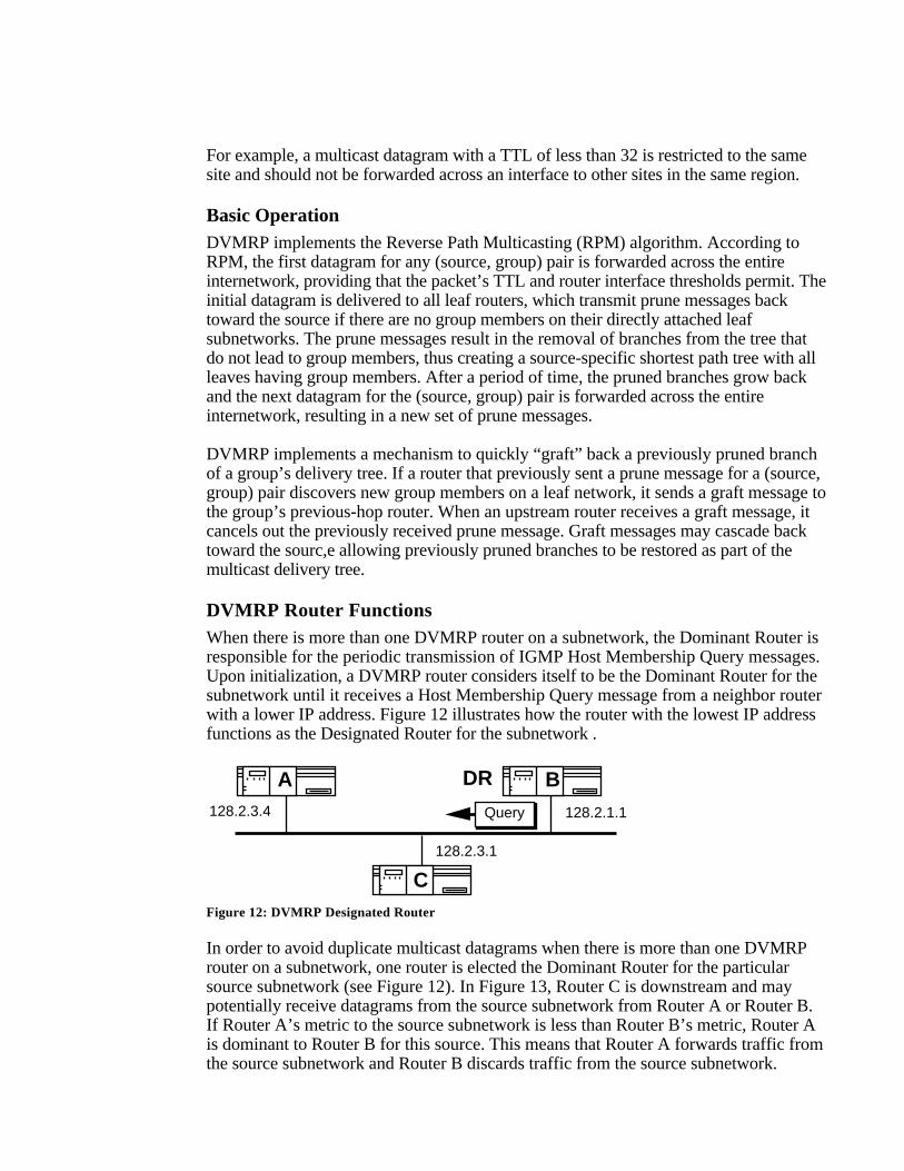
DVMRP Router FunctionsWhen there is more than one DVMRP router on a subnetwork, the Dominant Router isresponsible for the periodic transmission of IGMP Host Membership Query messages.Upon initialization, a DVMRP router considers itself to be the Dominant Router for thesubnetwork until it receives a Host Membership Query message from a neighbor routerwith a lower IP address. Figure 12 illustrates how the router with the lowest IP addressfunctions as the Designated Router for the subnetwork .
128.2.3.4 128.2.1.1
DR
Query
A B
C
128.2.3.1
Figure 12: DVMRP Designated Router
In order to avoid duplicate multicast datagrams when there is more than one DVMRProuter on a subnetwork, one router is elected the Dominant Router for the particularsource subnetwork (see Figure 12). In Figure 13, Router C is downstream and maypotentially receive datagrams from the source subnetwork from Router A or Router B.If Router A’s metric to the source subnetwork is less than Router B’s metric, Router Ais dominant to Router B for this source. This means that Router A forwards traffic fromthe source subnetwork and Router B discards traffic from the source subnetwork.
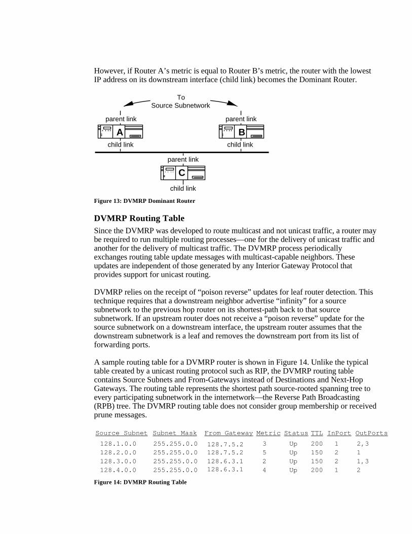
However, if Router A’s metric is equal to Router B’s metric, the router with the lowestIP address on its downstream interface (child link) becomes the Dominant Router.
parent link parent link
ToSource Subnetwork
parent link
child link child link
child link
A B
C
Figure 13: DVMRP Dominant Router
DVMRP Routing TableSince the DVMRP was developed to route multicast and not unicast traffic, a router maybe required to run multiple routing processes—one for the delivery of unicast traffic andanother for the delivery of multicast traffic. The DVMRP process periodicallyexchanges routing table update messages with multicast-capable neighbors. Theseupdates are independent of those generated by any Interior Gateway Protocol thatprovides support for unicast routing.
DVMRP relies on the receipt of “poison reverse” updates for leaf router detection. Thistechnique requires that a downstream neighbor advertise “infinity” for a sourcesubnetwork to the previous hop router on its shortest-path back to that sourcesubnetwork. If an upstream router does not receive a “poison reverse” update for thesource subnetwork on a downstream interface, the upstream router assumes that thedownstream subnetwork is a leaf and removes the downstream port from its list offorwarding ports.
A sample routing table for a DVMRP router is shown in Figure 14. Unlike the typicaltable created by a unicast routing protocol such as RIP, the DVMRP routing tablecontains Source Subnets and From-Gateways instead of Destinations and Next-HopGateways. The routing table represents the shortest path source-rooted spanning tree toevery participating subnetwork in the internetwork—the Reverse Path Broadcasting(RPB) tree. The DVMRP routing table does not consider group membership or receivedprune messages.
Source Subnet From Gateway InPort OutPortsMetric
128.1.0.0 128.7.5.2 3 1 2,3
Subnet Mask
255.255.0.0
Status
Up128.2.0.0 5 2 1255.255.0.0 Up128.3.0.0 2 2 1,3255.255.0.0 Up128.4.0.0 4 1 2255.255.0.0 Up
128.7.5.2128.6.3.1128.6.3.1
TTL
200150150200
Figure 14: DVMRP Routing Table
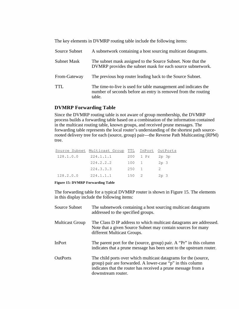
The key elements in DVMRP routing table include the following items:
Source Subnet A subnetwork containing a host sourcing multicast datagrams.
Subnet Mask The subnet mask assigned to the Source Subnet. Note that theDVMRP provides the subnet mask for each source subnetwork.
From-Gateway The previous hop router leading back to the Source Subnet.
TTL The time-to-live is used for table management and indicates thenumber of seconds before an entry is removed from the routingtable.
DVMRP Forwarding TableSince the DVMRP routing table is not aware of group membership, the DVMRPprocess builds a forwarding table based on a combination of the information containedin the multicast routing table, known groups, and received prune messages. Theforwarding table represents the local router’s understanding of the shortest path source-rooted delivery tree for each (source, group) pair—the Reverse Path Multicasting (RPM)tree.
Source Subnet Multicast Group InPort OutPortsTTL
128.1.0.0 224.1.1.1 200 1 Pr 2p 3p
224.2.2.2 100 1 2p 3
224.3.3.3 250 1 2
128.2.0.0 224.1.1.1 150 2 2p 3
Figure 15: DVMRP Forwarding Table
The forwarding table for a typical DVMRP router is shown in Figure 15. The elementsin this display include the following items:
Source Subnet The subnetwork containing a host sourcing multicast datagramsaddressed to the specified groups.
Multicast Group The Class D IP address to which multicast datagrams are addressed.Note that a given Source Subnet may contain sources for manydifferent Multicast Groups.
InPort The parent port for the (source, group) pair. A “Pr” in this columnindicates that a prune message has been sent to the upstream router.
OutPorts The child ports over which multicast datagrams for the (source,group) pair are forwarded. A lower-case “p” in this columnindicates that the router has received a prune message from adownstream router.
Hierarchical DVMRPThe rapid growth of the MBONE is beginning to place increasing demands on itsrouters. The current version of the DVMRP treats the MBONE as a single, “flat”routing domain where each router is required to maintain detailed routing information toevery subnetwork on the MBONE. As the number of subnetworks continues toincrease, the size of the routing tables and of the periodic update messages will continueto grow. If nothing is done about these issues, the processing and memory capabilitiesof the MBONE routers will eventually be depleted and routing on the MBONE will fail.
Benefits of Hierarchical Multicast Routing
To overcome these potential threats, a hierarchical version of the DVMRP is underdevelopment. In hierarchical routing, the MBONE is divided into a number ofindividual routing domains. Each routing domain executes its own instance of amulticast routing protocol. Another protocol, or another instance of the same protocol, isused for routing between the individual domains. Hierarchical routing reduces thedemand for router resources because each router only needs to know the explicit detailsabout routing packets to destinations within its own domain, but knows nothing aboutthe detailed topological structure of any of the other domains. The protocol runningbetween the individual domains maintains information about the interconnection of thedomains, but not about the internal topology of each domain.
In addition to reducing the amount of routing information, there are several otherbenefits gained from the development of a hierarchical version of the DVMRP:
- Different multicast routing protocols may be deployed in each region ofthe MBONE. This permits the testing and deployment of new protocolson a domain-by-domain basis.
- The effects of an individual link or router failures are limited to onlythose routers operating within a single domain. Likewise, the effects ofany change to the topological interconnection of regions is limited toonly inter-domain routers. These enhancements are especiallyimportant when deploying a distance-vector routing protocol that canresult in relatively long convergence times.
- The count-to-infinity problem associated with distance-vector routingprotocols places limitations on the maximum diameter of the MBONEtopology. Hierarchical routing limits these diameter constraints to asingle domain, not to the entire MBONE.
L2
L2 L2
L2
Region A
Region B
Region F
Region C
L2
Region DL2
Region EL2
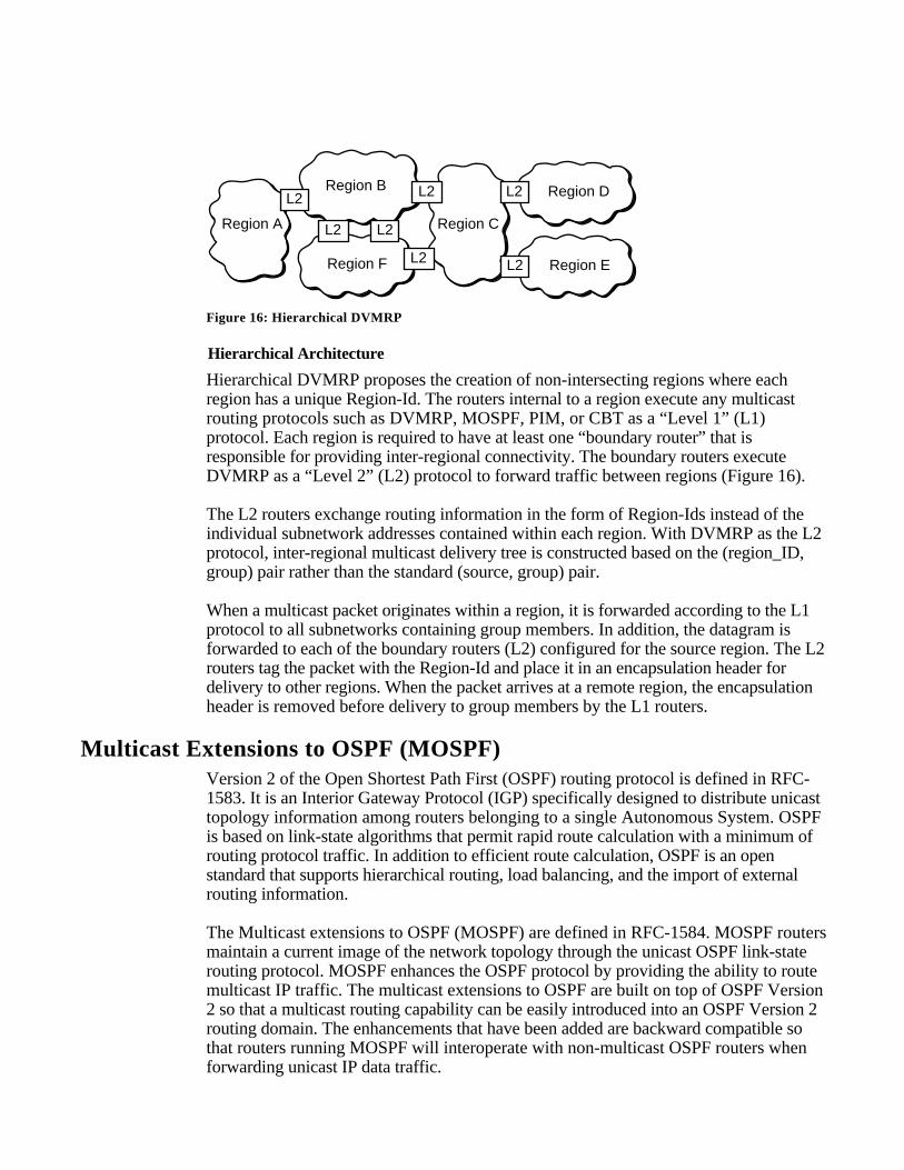
Figure 16: Hierarchical DVMRP
Hierarchical Architecture
Hierarchical DVMRP proposes the creation of non-intersecting regions where eachregion has a unique Region-Id. The routers internal to a region execute any multicastrouting protocols such as DVMRP, MOSPF, PIM, or CBT as a “Level 1” (L1)protocol. Each region is required to have at least one “boundary router” that isresponsible for providing inter-regional connectivity. The boundary routers executeDVMRP as a “Level 2” (L2) protocol to forward traffic between regions (Figure 16).
The L2 routers exchange routing information in the form of Region-Ids instead of theindividual subnetwork addresses contained within each region. With DVMRP as the L2protocol, inter-regional multicast delivery tree is constructed based on the (region_ID,group) pair rather than the standard (source, group) pair.
When a multicast packet originates within a region, it is forwarded according to the L1protocol to all subnetworks containing group members. In addition, the datagram isforwarded to each of the boundary routers (L2) configured for the source region. The L2routers tag the packet with the Region-Id and place it in an encapsulation header fordelivery to other regions. When the packet arrives at a remote region, the encapsulationheader is removed before delivery to group members by the L1 routers.
Multicast Extensions to OSPF (MOSPF)Version 2 of the Open Shortest Path First (OSPF) routing protocol is defined in RFC-1583. It is an Interior Gateway Protocol (IGP) specifically designed to distribute unicasttopology information among routers belonging to a single Autonomous System. OSPFis based on link-state algorithms that permit rapid route calculation with a minimum ofrouting protocol traffic. In addition to efficient route calculation, OSPF is an openstandard that supports hierarchical routing, load balancing, and the import of externalrouting information.
The Multicast extensions to OSPF (MOSPF) are defined in RFC-1584. MOSPF routersmaintain a current image of the network topology through the unicast OSPF link-staterouting protocol. MOSPF enhances the OSPF protocol by providing the ability to routemulticast IP traffic. The multicast extensions to OSPF are built on top of OSPF Version2 so that a multicast routing capability can be easily introduced into an OSPF Version 2routing domain. The enhancements that have been added are backward compatible sothat routers running MOSPF will interoperate with non-multicast OSPF routers whenforwarding unicast IP data traffic.
MOSPF, unlike DVMRP, does not provide support for tunnels.
Intra-Area Routing with MOSPFIntra-Area Routing describes the basic routing algorithm employed by MOSPF. Thiselementary algorithm runs inside a single OSPF area and supports multicast forwardingwhen the source and all destination group members reside in the same OSPF area, orwhen the entire Autonomous System is a single OSPF area. The following discussionassumes that the reader is familiar with the basic operation of the OSPF routingprotocol.
Local Group Database
Similar to the DVMRP, MOSPF routers use the Internet Group Management Protocol(IGMP) to monitor multicast group membership on directly attached subnetworks.MOSPF routers are required to implement a “local group database” that maintains a listof directly attached group members and determines the local router’s responsibility fordelivering multicast datagrams to these group members.
On any given subnetwork, the transmission of IGMP Host Membership Queries isperformed solely by the Designated Router (DR). Also, the responsibility of listening toIGMP Host Membership Reports is performed only by the Designated Router (DR)and the Backup Designated Router (BDR). This means that in a mixed environmentcontaining both MOSPF and OSPF routers, an MOSPF router must be elected the DRfor the subnetwork if IGMP Queries are to be generated. This can be achieved bysimply assigning all non-MOSPF routers a RouterPriority of 0 to prevent them frombecoming the DR or BDR, thus allowing an MOSPF router to become the DR for thesubnetwork.
The DR is responsible for communicating group membership information to all otherrouters in the OSPF area by flooding Group-Membership LSAs. The DR originates aseparate Group-Membership LSA for each multicast group having one or more entriesin the DR’s local group database. Similar to Router-LSAs and Network-LSAs, GroupMembership-LSAs are flooded throughout a single area only. This ensures that allremotely originated multicast datagrams are forwarded to the specified subnetwork fordistribution to local group members.
Datagram’s Shortest Path Tree
The datagram’s shortest path tree describes the path taken by a multicast datagram as ittravels through the internetwork from the source subnetwork to each of the individualgroup members. The shortest path tree for each (source, group) pair is built “ondemand” when a router receives the first multicast datagram for a particular (source,group) pair.
When the initial datagram arrives, the source subnetwork is located in the MOSPF linkstate database. The MOSPF link state database is simply the standard OSPF link statedatabase with the addition of Group-Membership LSAs. Based on the Router-LSAs andNetwork-LSAs in the MOSPF link state database, a source-rooted shortest-path tree is
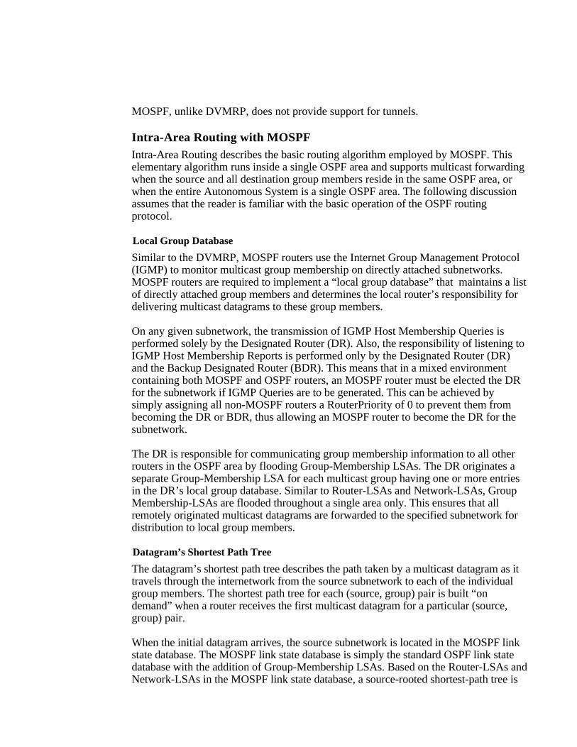
constructed using Dijkstra’s algorithm. After the tree is built, Group-Membership LSAsare used to prune those branches that do not lead to subnetworks containing individualgroup members. The result of the Dijkstra calculation is a pruned shortest-path treerooted at the datagram’s source.
A
B C
D E F
S
IHG
1 2
3 4 5
6 7 8
Figure 17: Shortest Path Tree for (S, G)
To forward a multicast datagram to downstream members of the group, each routermust determine its position in the datagram’s shortest path delivery tree. Assume thatFigure 17 illustrates the shortest path tree for a particular (source, group) pair. RouterE’s upstream node is Router B and there are two downstream interfaces: one connectingto Subnetwork 6 and another connecting to Subnetwork 7.
Note the following properties of the basic MOSPF routing algorithm:
- For a given multicast datagram, all routers within an OSPF areacalculate the same source-rooted shortest path delivery tree. Tie-breakers have been defined to guarantee that if several equal- cost pathsexist, all routers agree on a single path through the area. Unlike unicastOSPF, MOSPF does not support the concept of equal-cost multipathrouting.
- Synchronized link state databases containing Group-Membership LSAsallow an MOSPF router to effectively perform the Reverse PathMulticasting (RPM) computation “in memory”. Unlike DVMRP, thismeans that the first datagram of a group transmission does not have tobe forwarded to all routers in the area.
- The “on demand” construction of the shortest-path delivery tree has thebenefit of spreading calculations over time, resulting in a lesser impactfor participating routers.
Forwarding Cache
Each MOSPF router makes its forwarding decision based on the contents of itsforwarding cache. The forwarding cache is built from the source-rooted shortest-pathtree for each (source, group) pair and the router’s local group database. After the routerdiscovers its position in the shortest path tree, a forwarding cache entry is created
containing the (source, group) pair, the upstream node, and the downstream interfaces.At this point, the Dijkstra shortest path tree is discarded, releasing all resourcesassociated with the creation of the tree. From this point on, the forwarding cache entry isused to forward all subsequent datagrams for the (source, group) pair.
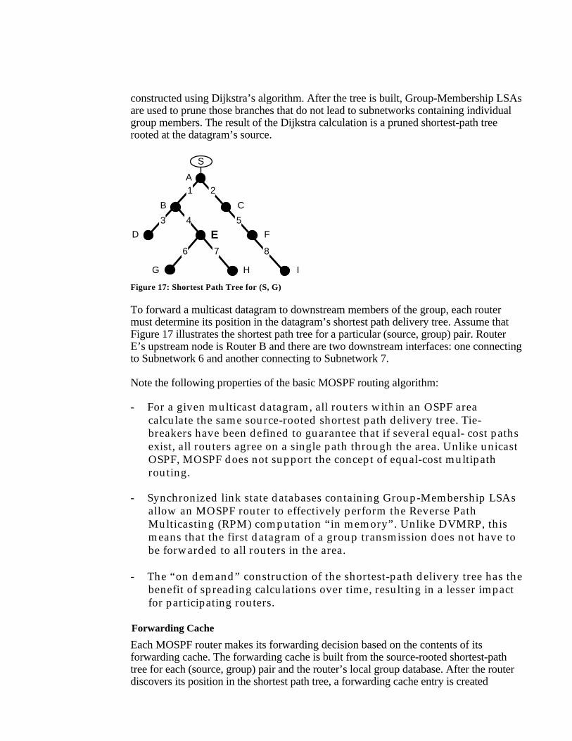
SourceDestination Upstream Downstream TTL
128.1.0.2224.1.1.1 5!1 !2 !3
224.2.2.2 128.2.0.3 7!2 !1
2!1 !2 !3 128.4.1.2224.1.1.13!1 !2 !3 128.5.2.2224.1.1.1
Figure 18: MOSPF Forwarding Cache
Figure 18 displays the forwarding cache for an example MOSPF router. The elementsin the display include the following items:
Destination The destination group address to which matching datagrams areforwarded.
Source The datagram’s source subnetwork. Each Destination/Source pairidentifies a separate forwarding cache entry.
Upstream The interface from which a matching datagram must be received.
Downstream The interfaces over which a matching datagram should beforwarded to reach Destination group members.
TTL The minimum number of hops a datagram will travel to reach themulticast group members. This allows the router to discarddatagrams that do not have a chance of reaching a destination groupmember.
The information in the forwarding cache is not aged or periodically refreshed. It ismaintained as long as there are system resources available (i.e., memory) or until thenext topology change. In general, the contents of the forwarding cache will changewhen:
- The topology of the OSPF internetwork changes, forcing all of thedatagram shortest-path trees to be recalculated.
- There is a change in the Group-Membership LSAs indicating that thedistribution of individual group members has changed.
Mixing MOSPF and OSPF RoutersMOSPF routers can be combined with non-multicast OSPF routers. This permits thegradual deployment of MOSPF and allows experimentation with multicast routing on alimited scale. When MOSPF and non-multicast OSPF routers are mixed within an
Autonomous System, all routers will interoperate in the forwarding of unicastdatagrams.
It is important to note that an MOSPF router is required to eliminate all non-multicastOSPF routers when it builds its source-rooted shortest-path delivery tree. An MOSPFrouter can easily determine the multicast capability of any other router based on thesetting of the multicast bit (MC-bit) in the Options field of each router’s link stateadvertisements. The omission of non-multicast routers can create a number of potentialproblems when forwarding multicast traffic:
- Multicast datagrams may be forwarded along suboptimal routes sincethe shortest path between two points may require traversal of a non-multicast OSPF router.
- Even though there is unicast connectivity to a destination, there maynot be multicast connectivity. For example, the network may partitionwith respect to multicast connectivity since the only path between twopoints requires traversal of a non-multicast OSPF router.
- The forwarding of multicast and unicast datagrams between two pointsmay follow entirely different paths through the internetwork. This maymake some routing problems a bit more difficult to debug.
- The Designated Router for a multi-access network must be an MOSPFrouter. If a non-multicast OSPF router is elected the DR, the subnetworkwill not be selected to forward multicast datagrams since a non-multicast DR cannot generate Group-Membership LSAs for itssubnetwork.
Inter-Area Routing with MOSPFInter-area routing involves the case where a datagram’s source and some of itsdestination group members reside in different OSPF areas. It should be noted that theforwarding of multicast datagrams continues to be determined by the contents of theforwarding cache which is still built from the local group database and the datagramshortest-path trees. The major differences are related to the way that group membershipinformation is propagated and the way that the inter-area shortest-path tree isconstructed.
Inter-Area Multicast Forwarders
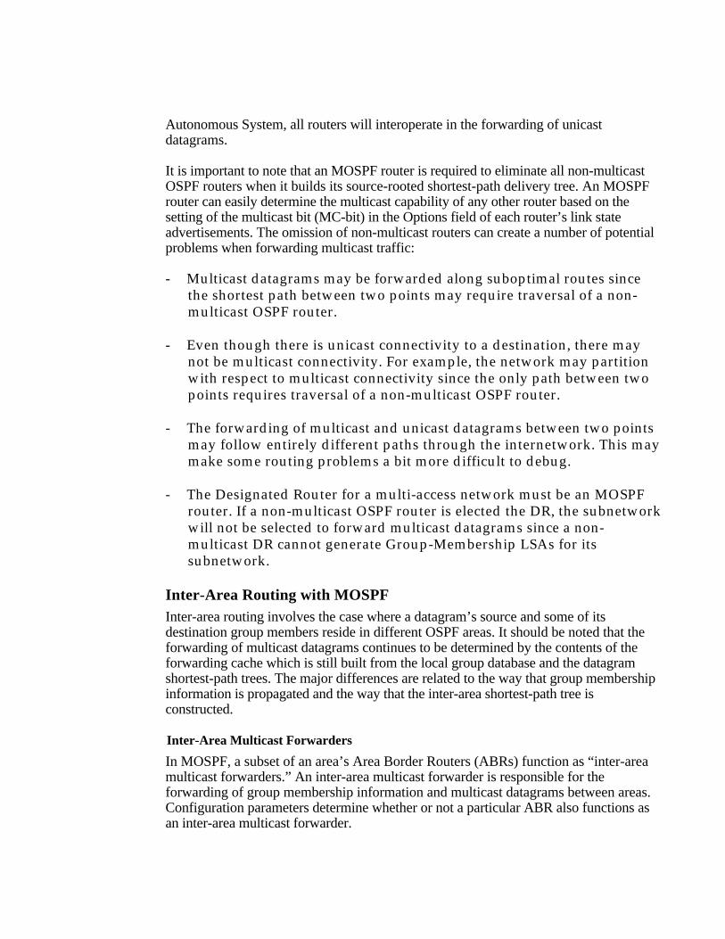
In MOSPF, a subset of an area’s Area Border Routers (ABRs) function as “inter-areamulticast forwarders.” An inter-area multicast forwarder is responsible for theforwarding of group membership information and multicast datagrams between areas.Configuration parameters determine whether or not a particular ABR also functions asan inter-area multicast forwarder.
Inter-area multicast forwarders summarize their attached areas’ group membershipinformation to the backbone by originating new Group-Membership LSAs into thebackbone area (Figure 19). It is important to note that the summarization of groupmembership in MOSPF is asymmetric. This means that group membershipinformation from non-backbone areas is flooded into the backbone. However, thebackbone does not readvertise either backbone group membership information or groupmembership information learned from other non-backbone areas into any non-backboneareas.
Area 1 Area 2
Backbone Area Group-Membership LSAs
Area Border Router andInter-Area Multicast Forwarder
*Wild-Card Multicast Receiver Interface
**
Figure 19: Inter-Area Routing Architecture
To permit the forwarding of multicast traffic between areas, MOSPF introduces theconcept of a “wild-card multicast receiver.” A wild-card multicast receiver is a routerthat receives all multicast traffic generated in an area, regardless of the multicast groupmembership. In non-backbone areas, all inter-area multicast forwarders operate as wild-card multicast receivers. This guarantees that all multicast traffic originating in a non-backbone area is delivered to its inter-area multicast forwarder, and then if necessary intothe backbone area. Since the backbone has group membership knowledge for all areas,the datagram can then be forwarded to group members residing in the backbone andother, non-backbone areas. The backbone area does not require wild-card multicastreceivers because the routers in the backbone area have complete knowledge of groupmembership information for the entire OSPF system.
Inter-Area Datagram Shortest-Path Tree
In the case of inter-area multicast routing, it is often impossible to build a completedatagram shortest-path delivery tree. Incomplete trees are created because detailedtopological and group membership information for each OSPF area is not distributedbetween OSPF areas. To overcome these limitations, topological estimates are madethrough the use of wild-card receivers and OSPF Summary-Links LSAs.
There are two cases that need to be considered when constructing an inter-area shortest-path delivery tree. The first involves the condition when the source subnetwork islocated in the same area as the router performing the calculation. The second situationoccurs when the source subnetwork is located in a different area than the routerperforming the calculation.
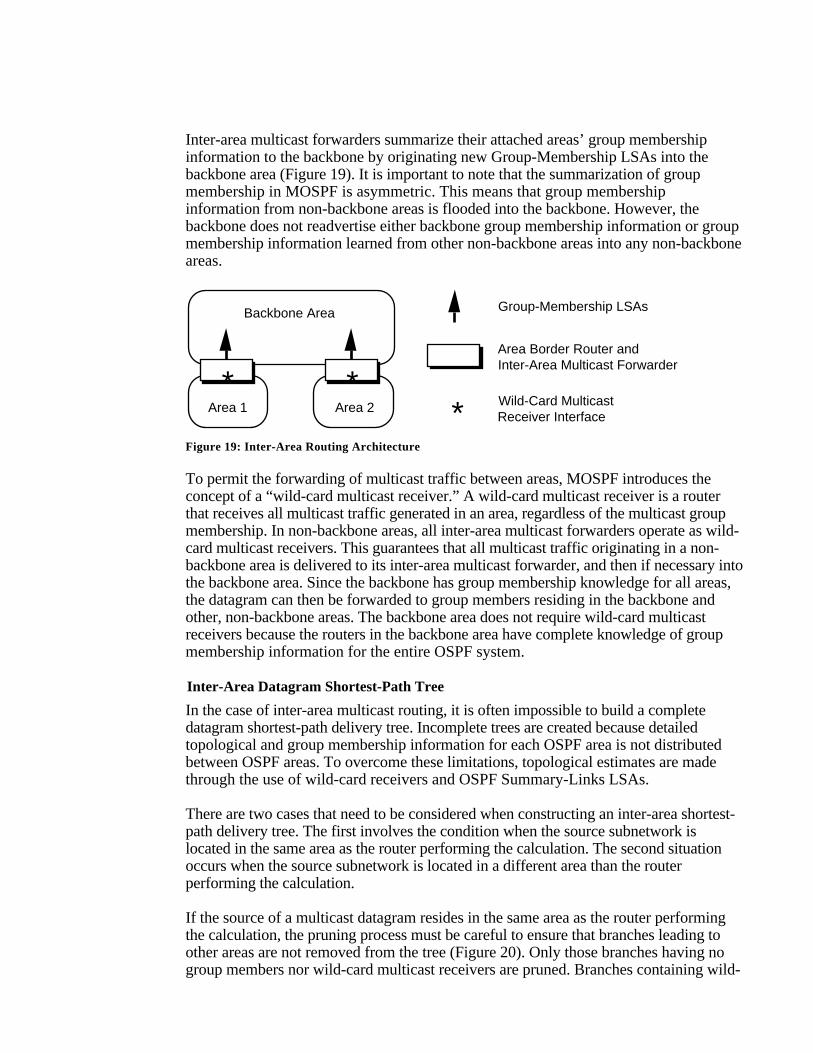
If the source of a multicast datagram resides in the same area as the router performingthe calculation, the pruning process must be careful to ensure that branches leading toother areas are not removed from the tree (Figure 20). Only those branches having nogroup members nor wild-card multicast receivers are pruned. Branches containing wild-
card multicast receivers must be retained, since the local routers do not know if there aregroup members residing in other areas.
S
Wild-Card Multicast Receiver
Area 1
Intra-area MOSPF router
Subnet containing group members
To other Areas
S Source subnetwork
Figure 20: Datagram Shortest-Path Tree—Source in Same Area
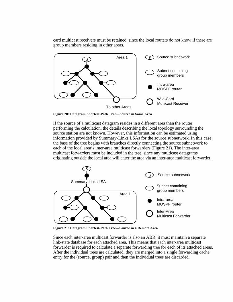
If the source of a multicast datagram resides in a different area than the routerperforming the calculation, the details describing the local topology surrounding thesource station are not known. However, this information can be estimated usinginformation provided by Summary-Links LSAs for the source subnetwork. In this case,the base of the tree begins with branches directly connecting the source subnetwork toeach of the local area’s inter-area multicast forwarders (Figure 21). The inter-areamulticast forwarders must be included in the tree, since any multicast datagramsoriginating outside the local area will enter the area via an inter-area multicast forwarder.
S
Area 1
Summary-Links LSA
Inter-Area Multicast Forwarder
Intra-area MOSPF router
Subnet containing group members
S Source subnetwork
Figure 21: Datagram Shortest-Path Tree—Source in a Remote Area
Since each inter-area multicast forwarder is also an ABR, it must maintain a separatelink-state database for each attached area. This means that each inter-area multicastforwarder is required to calculate a separate forwarding tree for each of its attached areas.After the individual trees are calculated, they are merged into a single forwarding cacheentry for the (source, group) pair and then the individual trees are discarded.
Inter-Autonomous System Multicasting with MOSPFInter-Autonomous System Multicasting involves the situation where a datagram’ssource and at least some of its destination group members reside in differentAutonomous Systems. It should be emphasized that in OSPF terminology “inter-AS”communication also refers to connectivity between an OSPF domain and anotherrouting domain that could be within the same Autonomous System.
To facilitate inter-AS multicast routing, selected Autonomous System BoundaryRouters (ASBRs) are configured as “inter-AS multicast forwarders.” MOSPF makesthe assumption that each inter-AS multicast forwarder executes an inter-AS multicastrouting protocol (such as DVMRP), which forwards multicast datagrams in a reversepath forwarding (RPF) manner. Each inter-AS multicast forwarder functions as a wild-card multicast receiver in each of its attached areas. This guarantees that each inter-ASmulticast forwarder remains on all pruned shortest-path trees and receives all multicastdatagrams, regardless of the multicast group membership.
Three cases need to be considered when describing the construction of an inter-ASshortest-path delivery tree. The first occurs when the source subnetwork is located in thesame area as the router performing the calculation. For the second case, the sourcesubnetwork resides in a different area than the router performing the calculation. Thefinal case occurs when the source subnetwork is located in a different AS (or in anotherrouting domain within the same AS) than the router performing the calculation.
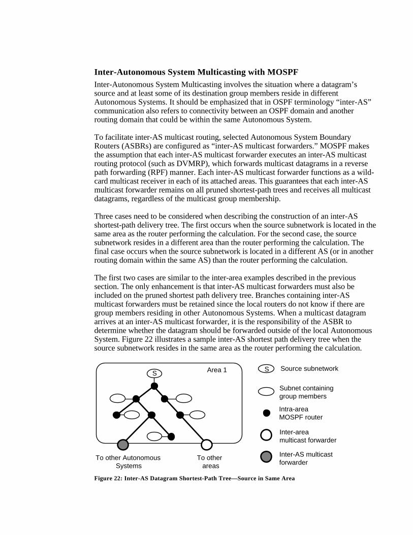
The first two cases are similar to the inter-area examples described in the previoussection. The only enhancement is that inter-AS multicast forwarders must also beincluded on the pruned shortest path delivery tree. Branches containing inter-ASmulticast forwarders must be retained since the local routers do not know if there aregroup members residing in other Autonomous Systems. When a multicast datagramarrives at an inter-AS multicast forwarder, it is the responsibility of the ASBR todetermine whether the datagram should be forwarded outside of the local AutonomousSystem. Figure 22 illustrates a sample inter-AS shortest path delivery tree when thesource subnetwork resides in the same area as the router performing the calculation.
S Area 1
To other areas
To other Autonomous Systems
Inter-area multicast forwarder
Intra-area MOSPF router
Subnet containing group members
Inter-AS multicastforwarder
S Source subnetwork
Figure 22: Inter-AS Datagram Shortest-Path Tree—Source in Same Area
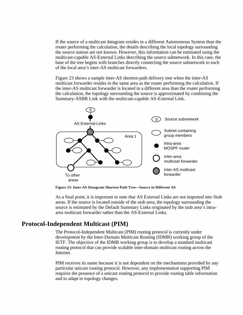
If the source of a multicast datagram resides in a different Autonomous System than therouter performing the calculation, the details describing the local topology surroundingthe source station are not known. However, this information can be estimated using themulticast-capable AS-External Links describing the source subnetwork. In this case, thebase of the tree begins with branches directly connecting the source subnetwork to eachof the local area’s inter-AS multicast forwarders.
Figure 23 shows a sample inter-AS shortest-path delivery tree when the inter-ASmulticast forwarder resides in the same area as the router performing the calculation. Ifthe inter-AS multicast forwarder is located in a different area than the router performingthe calculation, the topology surrounding the source is approximated by combining theSummary-ASBR Link with the multicast-capable AS-External Link.
S
Area 1
AS External-Links
To other areas
Inter-area multicast forwarder
Intra-area MOSPF router
Subnet containing group members
Inter-AS multicastforwarder
S Source subnetwork
Figure 23: Inter-AS Datagram Shortest-Path Tree—Source in Different AS
As a final point, it is important to note that AS External Links are not imported into Stubareas. If the source is located outside of the stub area, the topology surrounding thesource is estimated by the Default Summary Links originated by the stub area’s intra-area multicast forwarder rather than the AS-External Links.
Protocol-Independent Multicast (PIM)The Protocol-Independent Multicast (PIM) routing protocol is currently underdevelopment by the Inter-Domain Multicast Routing (IDMR) working group of theIETF. The objective of the IDMR working group is to develop a standard multicastrouting protocol that can provide scalable inter-domain multicast routing across theInternet.
PIM receives its name because it is not dependent on the mechanisms provided by anyparticular unicast routing protocol. However, any implementation supporting PIMrequires the presence of a unicast routing protocol to provide routing table informationand to adapt to topology changes.
PIM makes a clear distinction between a multicast routing protocol that is designed fordense environments and one that is designed for sparse environments. Dense-moderefers to a protocol that is designed to operate in an environment where group membersare relatively densely packed and bandwidth is plentiful. Sparse-mode refers to aprotocol that is optimized for environments where group members are distributed acrossmany regions of the Internet and bandwidth is not necessarily widely available. It isimportant to note that sparse-mode does not imply that the group has few members, justthat they are widely dispersed across the Internet.
The designers of PIM argue that DVMRP and MOSPF were developed forenvironments where group members are densely distributed. They emphasize that whengroup members and senders are sparsely distributed across a wide area, DVMRP andMOSPF do not provide the most efficient multicast delivery service. DVMRPperiodically sends multicast packets over many links that do not lead to group members,while MOSPF can send group membership information over links that do not lead tosenders or receivers.
PIM Dense Mode (PIM-DM)While the PIM architecture was driven by the need to provide scalable sparse-modedelivery trees, it also defines a new dense-mode protocol instead of relying on existingdense-mode protocols such as DVMRP and MOSPF. It is envisioned that PIM-DMwill be deployed in resource-rich environments, such as a campus LAN where groupmembership is relatively dense and bandwidth is likely to be readily available.
PIM Dense Mode (PIM-DM) is similar to DVMRP in that it employs the Reverse PathMulticasting (RPM) algorithm. However, there are several important differencesbetween PIM-DM and DVMRP:
- PIM-DM relies on the presence of an existing unicast routing protocol toadapt to topology changes, but it is independent of the mechanisms ofthe specific unicast routing protocol. In contrast, DVMRP contains anintegrated routing protocol that makes use of its own RIP-likeexchanges to compute the required unicast routing information.MOSPF uses the information contained in the OSPF link-state database,but MOSPF is specific to only the OSPF unicast routing protocol.
- Unlike DVMRP, which calculates a set of child interfaces for each(source, group) pair, PIM-DM simply forwards multicast traffic on alldownstream interfaces until explicit prune messages are received. PIM-DM is willing to accept packet duplication to eliminate routing protocoldependencies and to avoid the overhead involved in building theparent/child database.
For those cases where group members suddenly appear on a pruned branch of thedistribution tree, PIM-DM, like DVMRP, employs graft messages to add the previouslypruned branch to the delivery tree. Finally, PIM-DM control message processing and
data packet forwarding are integrated with PIM-Sparse Mode operation so that a singlerouter can run different modes for different groups.
PIM Sparse Mode (PIM-SM)PIM Sparse Mode (PIM-SM) is being developed to provide a multicast routing protocolthat provides efficient communication between members of sparsely distributed groups- the type of groups that are most common in wide-area internetworks. Its designersbelieve that a situation in which several hosts wish to participate in a multicastconference do not justify flooding the entire internetwork with periodic multicast traffic.They fear that existing multicast routing protocols will experience scaling problems ifseveral thousand small conferences are in progress, creating large amounts of aggregatetraffic that would potentially saturate most wide-area Internet connections. To eliminatethese potential scaling issues, PIM-SM is designed to limit multicast traffic so that onlythose routers interested in receiving traffic for a particular group “see” it.
PIM-SM differs from existing dense-mode multicast algorithms in two essential ways:
- Routers with directly attached or downstream members are required tojoin a sparse-mode distribution tree by transmitting explicit joinmessages. If a router does not become part of the predefined distributiontree, it will not receive multicast traffic addressed to the group. Incontrast, dense-mode multicast routing protocols assume downstreamgroup membership and continue to forward multicast traffic ondownstream links until explicit prune messages are received. Thedefault forwarding action of the other dense-mode multicast routingprotocols is to forward traffic, while the default action of a sparse-modemulticast routing protocol is to block traffic unless it is explicitlyrequested.
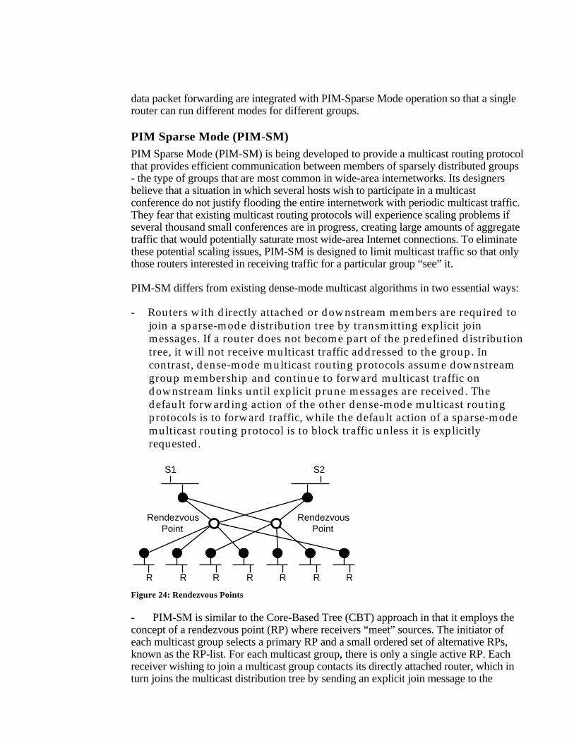
S1 S2
RendezvousPoint
R R R R R R R
RendezvousPoint
Figure 24: Rendezvous Points
- PIM-SM is similar to the Core-Based Tree (CBT) approach in that it employs theconcept of a rendezvous point (RP) where receivers “meet” sources. The initiator ofeach multicast group selects a primary RP and a small ordered set of alternative RPs,known as the RP-list. For each multicast group, there is only a single active RP. Eachreceiver wishing to join a multicast group contacts its directly attached router, which inturn joins the multicast distribution tree by sending an explicit join message to the
group’s primary RP. A source uses the RP to announce its presence and to find a path tomembers that have joined the group. This model requires sparse-mode routers tomaintain some state (i.e., the RP-list) prior to the arrival of data packets. In contrast,dense-mode multicast routing protocols are data driven, since they do not define anystate for a multicast group until the first data packet arrives.
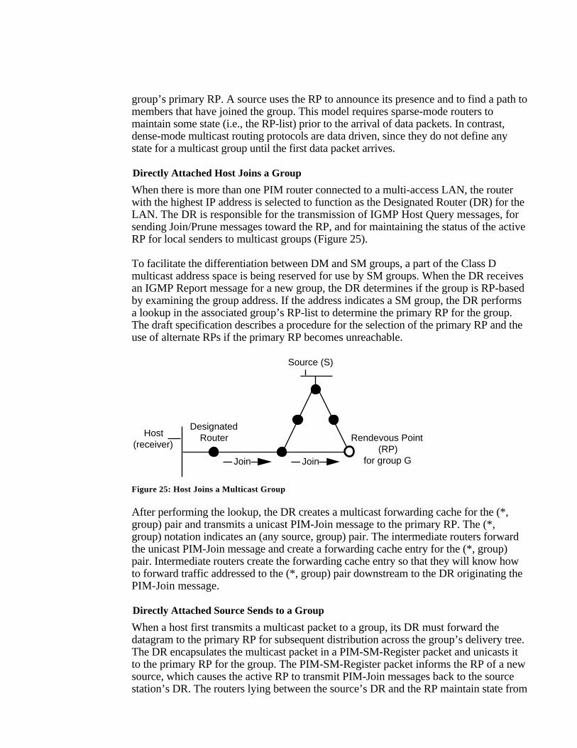
Directly Attached Host Joins a Group
When there is more than one PIM router connected to a multi-access LAN, the routerwith the highest IP address is selected to function as the Designated Router (DR) for theLAN. The DR is responsible for the transmission of IGMP Host Query messages, forsending Join/Prune messages toward the RP, and for maintaining the status of the activeRP for local senders to multicast groups (Figure 25).
To facilitate the differentiation between DM and SM groups, a part of the Class Dmulticast address space is being reserved for use by SM groups. When the DR receivesan IGMP Report message for a new group, the DR determines if the group is RP-basedby examining the group address. If the address indicates a SM group, the DR performsa lookup in the associated group’s RP-list to determine the primary RP for the group.The draft specification describes a procedure for the selection of the primary RP and theuse of alternate RPs if the primary RP becomes unreachable.
Host(receiver)
DesignatedRouter Rendevous Point
(RP)for group GJoin Join
Source (S)
Figure 25: Host Joins a Multicast Group
After performing the lookup, the DR creates a multicast forwarding cache for the (*,group) pair and transmits a unicast PIM-Join message to the primary RP. The (*,group) notation indicates an (any source, group) pair. The intermediate routers forwardthe unicast PIM-Join message and create a forwarding cache entry for the (*, group)pair. Intermediate routers create the forwarding cache entry so that they will know howto forward traffic addressed to the (*, group) pair downstream to the DR originating thePIM-Join message.
Directly Attached Source Sends to a Group
When a host first transmits a multicast packet to a group, its DR must forward thedatagram to the primary RP for subsequent distribution across the group’s delivery tree.The DR encapsulates the multicast packet in a PIM-SM-Register packet and unicasts itto the primary RP for the group. The PIM-SM-Register packet informs the RP of a newsource, which causes the active RP to transmit PIM-Join messages back to the sourcestation’s DR. The routers lying between the source’s DR and the RP maintain state from
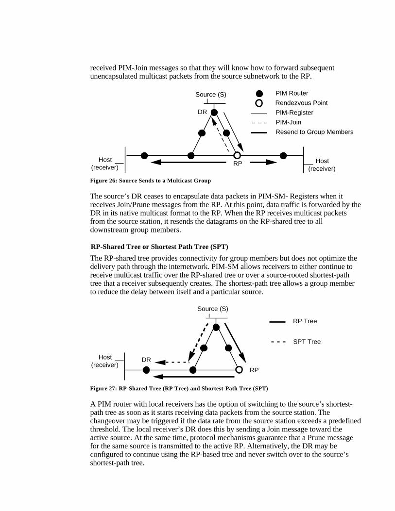
received PIM-Join messages so that they will know how to forward subsequentunencapsulated multicast packets from the source subnetwork to the RP.
Host(receiver)
RP
Source (S)
PIM-Register
PIM-Join
Resend to Group Members
DR
Host(receiver)
PIM Router
Rendezvous Point
Figure 26: Source Sends to a Multicast Group
The source’s DR ceases to encapsulate data packets in PIM-SM- Registers when itreceives Join/Prune messages from the RP. At this point, data traffic is forwarded by theDR in its native multicast format to the RP. When the RP receives multicast packetsfrom the source station, it resends the datagrams on the RP-shared tree to alldownstream group members.
RP-Shared Tree or Shortest Path Tree (SPT)
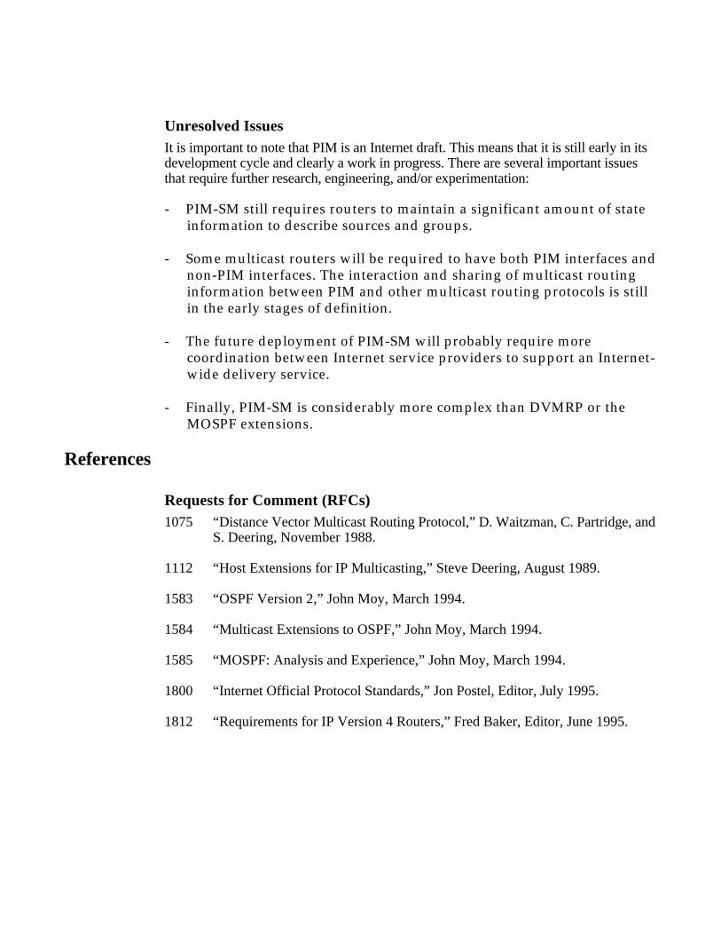
The RP-shared tree provides connectivity for group members but does not optimize thedelivery path through the internetwork. PIM-SM allows receivers to either continue toreceive multicast traffic over the RP-shared tree or over a source-rooted shortest-pathtree that a receiver subsequently creates. The shortest-path tree allows a group memberto reduce the delay between itself and a particular source.
Host(receiver)
DR
RP
Source (S)
RP Tree
SPT Tree
Figure 27: RP-Shared Tree (RP Tree) and Shortest-Path Tree (SPT)
A PIM router with local receivers has the option of switching to the source’s shortest-path tree as soon as it starts receiving data packets from the source station. Thechangeover may be triggered if the data rate from the source station exceeds a predefinedthreshold. The local receiver’s DR does this by sending a Join message toward theactive source. At the same time, protocol mechanisms guarantee that a Prune messagefor the same source is transmitted to the active RP. Alternatively, the DR may beconfigured to continue using the RP-based tree and never switch over to the source’sshortest-path tree.
Unresolved IssuesIt is important to note that PIM is an Internet draft. This means that it is still early in itsdevelopment cycle and clearly a work in progress. There are several important issuesthat require further research, engineering, and/or experimentation:
- PIM-SM still requires routers to maintain a significant amount of stateinformation to describe sources and groups.
- Some multicast routers will be required to have both PIM interfaces andnon-PIM interfaces. The interaction and sharing of multicast routinginformation between PIM and other multicast routing protocols is stillin the early stages of definition.
- The future deployment of PIM-SM will probably require morecoordination between Internet service providers to support an Internet-wide delivery service.
- Finally, PIM-SM is considerably more complex than DVMRP or theMOSPF extensions.
References
Requests for Comment (RFCs)1075 “Distance Vector Multicast Routing Protocol,” D. Waitzman, C. Partridge, and
S. Deering, November 1988.
1112 “Host Extensions for IP Multicasting,” Steve Deering, August 1989.
1583 “OSPF Version 2,” John Moy, March 1994.
1584 “Multicast Extensions to OSPF,” John Moy, March 1994.
1585 “MOSPF: Analysis and Experience,” John Moy, March 1994.
1800 “Internet Official Protocol Standards,” Jon Postel, Editor, July 1995.
1812 “Requirements for IP Version 4 Routers,” Fred Baker, Editor, June 1995.
Internet Drafts“Core Based Trees (CBT) Multicast: Architectural Overview,” <draft-ietf-idmr-cbt-arch-02.txt>, A. J. Ballardie, June 20, 1995.
“Core Based Trees (CBT) Multicast: Protocol Specification,” <draft-ietf-idmr-cbt-spec-03.txt>, A. J. Ballardie, November 21, 1995.
“Hierarchical Distance Vector Multicast Routing for the MBONE,” Ajit Thyagarajanand Steve Deering, July 1995.
“Internet Group Management Protocol, Version 2,” <draft-ietf- idmr-igmp-v2-01.txt>,William Fenner, Expires April 1996.
“Internet Group Management Protocol, Version 3,” <draft-cain- igmp-00.txt>, BradCain, Ajit Thyagarajan, and Steve Deering, Expires March 8, 1996
“Protocol-Independent Multicast (PIM), Dense-Mode Protocol Specification,” <draft-ietf-idmr-PIM-DM-spec-01.ps>, D. Estrin, D. Farinacci, V. Jacobson, C. Liu, L. Wei,P. Sharma, and A. Helmy, January 17, 1996.
“Protocol-Independent Multicast (PIM): Motivation and Architecture,” <draft-ietf-idmr-pim-arch-01.ps>, S. Deering, D. Estrin, D. Farinacci, V. Jacobson, C. Liu, and L. Wei,January 11, 1995.
“Protocol-Independent Multicast-Sparse Mode (PIM-SM): Protocol Specification,”<draft-ietf-idmr-PIM-SM-spec-02.ps>, S. Deering, D. Estrin, D. Farinacci, V.Jacobson, C. Liu, L. Wei, P. Sharma, and A Helmy, September 7, 1995.
TextbooksComer, Douglas E. Internetworking with TCP/IP: Volume 1—Principles, Protocols,and Architecture, Second Edition. Englewood Cliffs, NJ: Prentice Hall, 1991.
Huitema, Christian. Routing in the Internet. Englewood Cliffs, NJ: Prentice Hall, 1995.
Stevens, W. Richard. TCP/IP Illustrated: Volume 1 The Protocols. Reading, MA:Addison Wesley, 1994.
Wright, Gary, and W. Richard Stevens. TCP/IP Illustrated: Volume 2—TheImplementation. Reading, MA: Addison Wesley, 1995
OtherDeering, Steven E. “Multicast Routing in a Datagram Internetwork,” Ph.D. Thesis,Stanford University, December 1991.
Ballardie, Anthony J. “A New Approach to Multicast Communication in a DatagramInternetwork,” Ph.D. Thesis, University of London, May 1995.
Recommended


![MikroTik Multicast Routing []](https://img.dokumen.tips/doc/110x75/55a6073e1a28abf4248b4775/mikrotik-multicast-routing-wwwimxpertco.jpg)