ENERGYPLUS™
COPYRIGHT © 1998-2013 The Board of Trustees of the University of Illinois and the Regents of the University of California throughthe Ernest Orlando Lawrence Berkeley National Laboratory.
All Rights Reserved. No part of this material may be reproduced or transmitted in any form or by any means without the prior writtenpermission of the University of Illinois or the Ernest Orlando Lawrence Berkeley National Laboratory.
EnergyPlus is a Trademark of the US Department of Energy.
Guide for Interface Developers
EverythingYou Need to Know about EnergyPlusInput and Output(todevelopauser-friendlyinterface)
Date: April 1, 2013
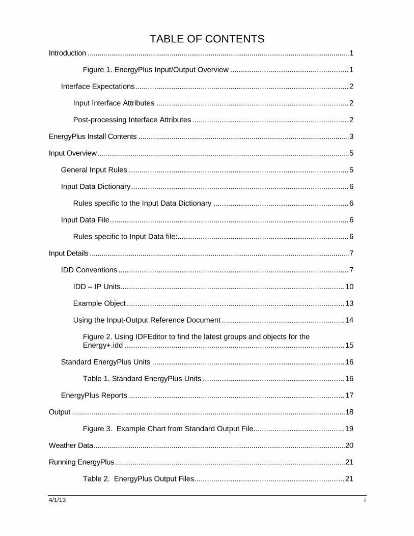
TABLE OF CONTENTS
4/1/13 i
Introduction ......................................................................................................................................1
Figure 1. EnergyPlus Input/Output Overview ........................................................1
Interface Expectations.....................................................................................................2
Input Interface Attributes ...........................................................................................2
Post-processing Interface Attributes ..........................................................................2
EnergyPlus Install Contents ............................................................................................................3
Input Overview.................................................................................................................................5
General Input Rules ........................................................................................................5
Input Data Dictionary.......................................................................................................6
Rules specific to the Input Data Dictionary ................................................................6
Input Data File.................................................................................................................6
Rules specific to Input Data file:.................................................................................6
Input Details .....................................................................................................................................7
IDD Conventions .............................................................................................................7
IDD – IP Units..........................................................................................................10
Example Object .......................................................................................................13
Using the Input-Output Reference Document ..........................................................14
Figure 2. Using IDFEditor to find the latest groups and objects for theEnergy+.idd ........................................................................................................15
Standard EnergyPlus Units ...........................................................................................16
Table 1. Standard EnergyPlus Units ...................................................................16
EnergyPlus Reports ......................................................................................................17
Output ............................................................................................................................................18
Figure 3. Example Chart from Standard Output File...........................................19
Weather Data.................................................................................................................................20
Running EnergyPlus......................................................................................................................21
Table 2. EnergyPlus Output Files.......................................................................21

TABLE OF CONTENTS
4/1/13 ii
Table 3. EnergyPlus Errors ................................................................................22
Table 4. Timings Comparison (EnergyPlus vs. BLAST) .....................................22
Licensing........................................................................................................................................23
Appendix A. Simple IDF file..........................................................................................................24

Introduction Interface Expectations
4/1/13 1
Introduction
This document is intended for developers who are creating user interfaces for EnergyPlus. Itprovides an overview of the essentials of the input-output structure of EnergyPlus anddescribes the parts of each in detail.
File TypesData Dictionary File (IDD)File produced by Energy Plus developers.
Input Data File (IDF)File created by interfaces.
Weather Data File (EPW)File created by weather processor.
Section;Object,data,data,…,data;Object,data,data,…,data;End Section;
Input EnergyPlus ProgramMain Program
Module
Module
Module
Module
Module
Module
File Types:Standard ReportsStandard Reports (Detail)Optional ReportsOptional Reports (Detail)Initialization Reports
Overview of File Format:HeaderData DictionaryData
Note: These files willcreated by EnergyPlus.
Output
Overview of IDF Format
Figure 1. EnergyPlus Input/Output Overview
The diagram shown above should give the reader an overall picture of input-output inEnergyPlus. It can be seen as a linear process that includes the following steps:
1) The user enters building description (including internal space gains, HVACarrangements, and Plant equipment properties) using the interface of their choice. Inaddition, the user specifies which non-default reports are desired and any optionalvariables from a predefined list of available simulation quantities.
2) The interface program writes the Input Data File (IDF) file, which includes thespecification of any report items desired by the user.
3) EnergyPlus processes both the Input Data Dictionary (IDD) and the Input Data File (IDF)files with the “InputProcessor”. The InputProcessor uses the specifications/rules definedin the IDD and interprets the IDF raw data. The InputProcessor is really quite “dumb” andonly understands a few things about each field (alpha or numeric) qualified by certain keyelements in the IDD (\ comments which are discussed later).
4) Each module in EnergyPlus has one or several routines (normally called “GetInput”routines) that obtain the information from the IDF file data. These subroutines decodethe portion of the IDF file that is pertinent to the local module. These GetInput routinesare more context sensitive than the InputProcessor and may perform further errordetection. For example, the cooling coil module may read in the coil type and itsassociated parameters (number of rows, tube diameter, fin spacing, etc.).
5) EnergyPlus performs the simulation elements specified in the IDF. Output is generatedas a continuous stream (for the most part) and must be interpreted into a more cohesiveform by output processing. The user has control over which outputs are produced andwhen/how often.
6) EnergyPlus produces output as required by the user into one of the output files. Thesefiles can be readily processed into spreadsheet formats for graphing and othersummarizing.

Introduction Interface Expectations
4/1/13 2
Interface Expectations
The input-output interfaces may be combined into a single program or may be availableseparately. The following attributes are expected from these interfaces.
Input Interface Attributes
The input interface agents will be expected to fulfill two main requirements:
Ability to produce the input file for the simulation.
Perform the consistency and value checks necessary to assure that the input fileconforms to EnergyPlus requirements.
Additionally, the input interface agent might:
Ability to warn users about potential output file size. It is expected that the data filesgenerated by the EnergyPlus program will be significantly larger than the output files fromits parent programs. As a result, users may be unaware that selecting too many reportscould lead to enormous output files. It is recommended that some sort of checking bedone to alert users when the term of the simulation and the number of reports selectedeclipse some reasonable file size limit.
Ability to perform parametric runs.
The method used by the input interface agent to accomplish these goals is left to thediscretion of the interface developer.
Post-processing Interface Attributes
The post-processing agents will be expected to fulfill the main requirement:
Ability to read all or selected output formats.
Additionally, a post-processing agent might:
Ability to combine and summarize data (average, peak, total, etc.) and produce thevarious text and graphical reports requested by the user.
Ability to handle multiple output files.
The method used by the post-processing agent to accomplish these goals is left to thediscretion of the interface developer.

EnergyPlus Install Contents Interface Expectations
4/1/13 3
EnergyPlus Install Contents
EnergyPlus Interfaces will naturally need to access the installed EnergyPlus programs, libraryfiles, documentation. It will help to describe how EnergyPlus is installed (on a Windows™computer). The EnergyPlus install is written using the WISE™ installation software.
The scheme of installing EnergyPlus includes a “root” directory/folder and all subsequentprograms installed as part of the installation are child folders under the parent/root folder.Several optional components can be selected during install.
The basic (required) installation has crucial files installed in the parent folder – these includeEnergyPlus.exe, Energy+.idd (the input data dictionary), EPMacro.exe. The basicinstallation also includes a child folder “DataSets” that contains the EnergyPlus “libraries”. Asdistributed, EnergyPlus includes several library files, formatted in the standard EnergyPlusIDF format. These include thermal material properties, moisture material properties, glassand other properties for windows, constructions (material sandwiches which describe walls,windows, roofs), fluid properties, locations, design day definitions, and basic scheduledefinitions. There, of course, may be additional data sets added as well as future datasetsedited for selectable use from the EPMacro program. The Templates folder is also includedin the basic install. Currently, the Templates folder contains documentation and the HVACTemplate files. These files can be used somewhat “automatically” to produce HVAC loopstructures for running with EnergyPlus.
Optional components of the EnergyPlus install: Documentation, EP-Launch, IDFEditor,Sample Files, Weather Converter, and other auxiliary type programs. All the componentsare selected by default; to not install them the user must “un-select” them individually.Highlights of several:
Documentation: The EnergyPlus package includes a comprehensive set of documentsintended to help the user and others understand the EnergyPlus program, usage, and otherappropriate information. All documents are created in PDF (Portable Document Format).There isA shortcut to the Documentation folder and the “main-menu” document is included.The main-menu document is a navigation aid to the remainder of the documents. We maywant to make the documentation a non-optional component.
EP-Launch: The components of EP-Launch are installed in the parent directory (help filesinstalled in the documentation directory). Because the basic EnergyPlus program runs as aconsole application, many beta users did not understand how to make the program execute.While the developers may be able to tailor the EnergyPlus executable to be more callableunder the Windows™ platform, this is still a useful program. EP-Launch uses the EPL-Run.bat file and prepends several “set” commands that are used in the bat file. It creates theactual batch file for the run as “RunEP.bat” and then calls the operating system to executethe file. Having the EPL-Run.bat file as external to the EP-Launch program means thatothers may tailor the batch file more appropriately to how things are run though this may notbe preserved with a future EnergyPlus install. EP-Launch can also execute several utilityprograms from the “Utilities” tab.
IDFEditor: The IDFEditor is the simple editor that is distributed with EnergyPlus. As aninterface, it is crude. However, it gets the job done. It uses the IDD and then reads and/orcreates an IDF file. The objects are shown in the groups (see \group discussion below) and,when an existing file is used, will display how many of an object is found in the IDF. Thisprogram is installed in the Parent \ PreProcess \ IDFEditor folder.
Sample Files: The sample files include several IDF files along with the files the installedversion of EnergyPlus created using these files. There are several possible child foldershere, including the Misc child folder that will contain all the development sample files – butwithout having been run for the install. These files are installed in the Parent \ ExampleFilesfolder and any appropriate child folders under that.

EnergyPlus Install Contents Interface Expectations
4/1/13 4
Weather Converter: The WeatherConverter program can process raw weather data inseveral formats into the EnergyPlus weather data format (epw). In addition, theWeatherConverter program can be used to generate a simple report of the weather data aswell as produce a .csv file of the format. The .csv (comma separated variable) format caneasily be imported into spread sheet programs or other tables. This program is installed inthe Parent \ PreProcess \ WeatherConverter folder. The WeatherConverter also has a DLLfile which could be used directly by an external interface.
BLAST Translator: The BLAST translator program can be used to convert a BLAST inputfile into a format that can be executed from EnergyPlus. Extensive system translation is notdone with this program – mostly geometry and other space gain elements as well as zoneoriented (i.e. People) schedules. If the BLAST input file contains thermostatic controls in thezones, then the EnergyPlus IDF file will include a purchased-air solution of that BLAST inputfile. This program is no longer part of the EnergyPlus install but is available with each newrelease.
DOE-2 Translator: The DOE-2 translator program is similar to the BLAST Translatorprogram but for DOE-2 files. DOE-2 translator output must be processed by the EPMacroprogram prior to running in EnergyPlus (the EP-Launch program/EPL-Run procedure doesthis automatically for all “.imf” files). This program is no longer part of the EnergyPlus installbut is available with each new release.

Input Overview General Input Rules
4/1/13 5
Input Overview
The general structure of the input files for EnergyPlus is plain text. Fields are commadelimited and each “line” is terminated with a semicolon. This allows for a very rudimentaryinput processor that can be instantly flexible to developer’s needs. However, it puts moreburdens on the EnergyPlus developers to process the input information, supply defaults asneeded, and perform validity checks. Guidelines were established for the input:
Input will be a flat ASCII file with comma-delimited columns and each “line” (where eachline can run over several physical file records) terminated with a semicolon.
Input should be “readable”, “editable”, “simply parsed with few value checks orconsistency checks”.
Input, to the extent possible, should be easily maintainable and extendable.
Input will be “object based”.
Definitions in a data dictionary will define the input. The data dictionary should be self-documenting.
All input units will be metric (SI). Conversions from “user units” will be done in theinterface agents.
Two input files are necessary for the input processing. The first is the “data dictionary” whichwill specify the requirements for each item. The EnergyPlus Input Processor uses theserequirements to process the “input data file” and report any anomalies found. Both input fileshave similar structures: 1) Sections – single lines/commands, which may help group thesimulation input for readability and 2) Classes/Objects – data attributes for the simulation.Classes are the term used in the data dictionary – each class will specify the kind of data(alpha or numeric) that will be included in the simulation input. Objects are instances of theseclasses and appear in the IDF with appropriate data.
General Input Rules
The following rules apply to both the Input Data Dictionary and the Input Data File.
The initial line of a definition or input MUST have a comma or semicolon.
Fields do not extend over line boundaries. Usually, if a comma or (as appropriate) semi-colon is not the last field value on a line, one will be inserted. Of course, several fieldsmay appear on a single line as long as they are comma separated.
Commas delimit fields – therefore, no fields can have embedded commas. No error willoccur but you won't get what you want.
Blank lines are allowed.
The comment character is a exclamation “!”. Anything on a line after the exclamation isignored.
A special type of comment using the character combination: “!-“ in the input file is aspecial form of comment that is followed by the field name(s) and units and should notinclude user provided text. This form is used to indicate automatic comments which maybe written by interfaces and other utilities as an endline comment after a field value.
Input records can be up to 500 characters in length. If you go over that, no error willoccur but you won't get what you want.
Each Section and Class/Object keyword can be up to 100 characters in length.Embedded spaces are allowed, but are significant (if you have 2 spaces in the sectionkeyword – you must have 2 when you write the object keyword).
Each Alpha string (including Section and Class/Object keywords) is mapped to UPPERcase during processing, unless the “retaincase” flag marks the field in the IDD. Getroutines from the EnergyPlus code that use the Section and Object keywords

Input Overview Input Data Dictionary
4/1/13 6
automatically map to UPPER case for finding the item. The primary drawback with this isthat error messages coming out of the input processor will be in UPPER case and maynot appear exactly as input.
Special characters, such as tabs, should NOT be included in the file. However, tabs canbe accommodated and are turned into spaces.
Input Data Dictionary
The input data dictionary specifies the “definitions” for each line that will be processed in theinput data file.
Structure in the input data dictionary allows for descriptions that may be useful for interfacedevelopers. The Input Processor ignores everything but the essentials for getting the “rightstuff” into the program. Developers have been (and will continue to be) encouraged toinclude comments and other documentation in the IDD.
Internal to the data dictionary (using special “comment” characters) is a structured set ofconventions for including information on each object. This is shown in section on InputDetails below.
Rules specific to the Input Data Dictionary
In addition to the rules for both files (listed above), the IDD also has the limitation:
Duplicate Section names and Duplicate Class names are not allowed. That is, the firstclass of an item named X will be the one used during processing. Error messages willappear if you try to duplicate definitions.
Input Data File
This is the only file that EnergyPlus uses to create the building simulation. The input is order-independent; data can appear in any order and will be retrieved and sorted as necessary bythe EnergyPlus simulation modules. In addition, EnergyPlus allocates everythingdynamically, so there are no limitations as to number of zones, surfaces, etc.
All numbers can be flexibly input and are processed into single precision variables (i.e. 1.0,1.000, 1, .1E+1 are all processed equally).
Rules specific to Input Data file:
Each Alpha string in the input data file can be up to 100 characters in length. Anythingbeyond that is truncated.
A special combination of characters “!-“ indicates a comment that contains the name andunits of the field after each field value. These, like normal comments, are ignored byEnergyPlus. This type of comment containing the field names are created automaticallywith IDF Editor, IDF Version Updater (transition) and other user interfaces. Commentsadded by the user should not use “!-“ because they are deleted and replaced with thefield name when the file is saved using IDF Editor. For an example of this syntax, see theexample file in Appendix A.

Input Details IDD Conventions
4/1/13 7
Input Details
This document does not cover the input “classes” in detail. For details on each class andexamples of both input and output resulting from that class/object, please view the InputOutput Reference document. In this document, we will show the “conventions” used in theIDD and provide limited examples for illustration purposes. Even the list of objects isdynamic, so we give you a method to see them from the IDFEditor.
An intelligent editor (IDFEditor) has been written and can be used as an illustration of how thecomments in the IDD might be used by Interface Developers to guide their developments.IDFEditor is described in the Getting Started document.
A full example of a very simple IDF is included in Appendix A to this document.
IDD Conventions
The following is a basic description of the structure of the IDD (it’s actually taken directly fromthe IDD file). As noted within, ! signifies a comment character as does the \. \ has also beenadopted as a convention for including more specific comments about each field in an object.These have been used with success in the IDFEditor and it is hoped the flexibility will provideother interface developers with useful information.
!IDD_Version VERSION NUMBER! **************************************************************************! This file is the Input Data Dictionary (IDD) for EnergyPlus.! The IDD defines the syntax and data model for each type of input "Object."! Lines in EnergyPlus input files (and IDD) are limited to 500 characters.!! Object Description! ------------------! To define an object (a record with data), develop a key word that is unique! Each data item to the object can be A (Alphanumeric string) or N (numeric)! Number each A and N. This will show how the data items will be put into the! arrays that are passed to the Input Processor "Get" (GetObjectItem) routines.! All alpha fields are limited to 100 characters. Numeric fields should be! valid numerics (can include such as 1.0E+05) and are placed into double! precision variables.!! NOTE: Even though a field may be optional, a comma representing that field! must be included (unless it is the last field in the object). Since the! entire input is "field-oriented" and not "keyword-oriented", the EnergyPlus! Input Processor must have some representation (even if blank) for each! field.!! Object Documentation! --------------------! In addition, the following special comments appear one per line and! most are followed by a value. Comments may apply to a field or the object! or a group of objects.!! Field-level comments:!! \field Name of field! (should be succinct and readable, blanks are encouraged)!! \note Note describing the field and its valid values. If multiple lines,! start each line with \note. Limit line length to 100 characters.!! \required-field To flag fields which may not be left blank! (this comment has no "value")

Input Details IDD Conventions
4/1/13 8
!! \begin-extensible Marks the first field at which the object accepts an extensible! field set. A fixed number of fields from this marker define the! extensible field set, see the object code \extensible for! more information.!! \units Units (must be from EnergyPlus standard units list)! EnergyPlus units are standard SI units!! \ip-units IP-Units (for use by input processors with IP units)! This is only used if the default conversion is not! appropriate.!! \unitsBasedOnField For fields that may have multiple possible units, indicates! the field in the object that can be used to determine! the units. The field reference is in the A2 form.!! \minimum Minimum that includes the following value!! \minimum> Minimum that must be > than the following value!! \maximum Maximum that includes the following value!! \maximum< Maximum that must be < than the following value!! \default Default for the field (if N/A then omit entire line)!! \deprecated This field is not really used and will be deleted from the object.! The required information is gotten internally or! not needed by the program.!! \autosizable Flag to indicate that this field can be used with the Auto! Sizing routines to produce calculated results for the! field. If a value follows this, then that will be used! when the "Autosize" feature is flagged. To trigger! autosizing for a field, enter Autosize as the field's! value. Only applicable to numeric fields.!! \autocalculatable Flag to indicate that this field can be automatically! calculated. To trigger auto calculation for a field, enter! Autocalculate as the field's value. Only applicable to! numeric fields.!! \type Type of data for the field -! integer! real! alpha (arbitrary string),! choice (alpha with specific list of choices, see! \key)! object-list (link to a list of objects defined elsewhere,! see \object-list and \reference)! external-list (uses a special list from an external source,! see \external-list)! node (name used in connecting HVAC components)!! \retaincase Retains the alphabetic case for alpha type fields!! \key Possible value for "\type choice" (blanks are significant)! use multiple \key lines to indicate all valid choices!! \object-list Name of a list of user-provided object names that are valid! entries for this field (used with "\reference")! see Zone and BuildingSurface:Detailed objects below for

Input Details IDD Conventions
4/1/13 9
! examples.! ** Note that a field may have multiple \object-list commands.!! \external-list The values for this field should be selected from a special! list generated outside of the IDD file. The choices for the! special lists are:! autoRDDvariable! autoRDDmeter! autoRDDvariableMeter! When one of these are selected the options for the field! are taken from the RDD or MDD file or both.!! \reference Name of a list of names to which this object belongs! used with "\type object-list" and with "\object-list"! see Zone and BuildingSurface:Detailed objects below for! examples:!! Zone,! A1 , \field Name! \type alpha! \reference ZoneNames!! BuildingSurface:Detailed,! A4 , \field Zone Name! \note Zone the surface is a part of! \type object-list! \object-list ZoneNames!! For each zone, the field "Name" may be referenced! by other objects, such as BuildingSurface:Detailed, so it is! commented with "\reference ZoneNames"! Fields that reference a zone name, such as BuildingSurface:Detailed's! "Zone Name", are commented as! "\type object-list" and "\object-list ZoneNames"! ** Note that a field may have multiple \reference commands.! ** This is useful if the object belongs to a small specific! object-list as well as a larger more general object-list.!! Object-level comments:!! \memo Memo describing the object. If multiple lines, start each line! with \memo.! Limit line length to 100 characters.!! \unique-object To flag objects which should appear only once in an idf! (this comment has no "value")!! \required-object To flag objects which are required in every idf! (this comment has no "value")!! \min-fields Minimum number of fields that should be included in the! object. If appropriate, the Input Processor will fill! any missing fields with defaults (for numeric fields).! It will also supply that number of fields to the "get"! routines using blanks for alpha fields (note -- blanks! may not be allowable for some alpha fields).!! \obsolete This object has been replaced though is kept (and is read)! in the current version. Please refer to documentation as! to the dispersal of the object. If this object is! encountered in an IDF, the InputProcessor will post an! appropriate message to the error file.! usage: \obsolete New=>[New object name]

Input Details IDD Conventions
4/1/13 10
!! \extensible:<#> This object is dynamically extensible -- meaning, if you! change the IDD appropriately (if the object has a simple list! structure -- just add items to the list arguments (i.e. BRANCH! LIST). These will be automatically redimensioned and used during! the simulation. <#> should be entered by the developer to signify! how many of the last fields are needed to be extended (and EnergyPlus! will attempt to auto-extend the object). The first field of the first! instance of the extensible field set is marked with \begin-extensible.!! \begin-extensible See previous item, marks beginning of extensible fields in! an object.!! \format The object should have a special format when saved in! the IDF Editor with the special format option enabled.! The options include SingleLine, Vertices, CompactSchedule,! FluidProperties, ViewFactors, and Spectral.! The SingleLine option puts all the fields for the object! on a single line. The Vertices option is used in objects! that use X, Y and Z fields to format those three fields! on a single line.! The CompactSchedule formats that specific object.! The FluidProperty option formats long lists of fluid! properties to ten values per line.! The ViewFactor option formats three fields related to! view factors per line.! The Spectral option formats the four fields related to! window glass spectral data per line.!! \reference-class-name Adds the name of the class to the reference list! similar to \reference.!! Group-level comments:!! \group Name for a group of related objects!!! Notes on comments! -----------------!! 1. If a particular comment is not applicable (such as units, or default)! then simply omit the comment rather than indicating N/A.!! 2. Memos and notes should be brief (recommend 5 lines or less per block).! More extensive explanations are expected to be in the user documentation
IDD – IP Units
In addition, the IDD contains indications of IP (inch-pound) units for the EnergyPlus standardSI (Systems International) units. These may be used by input and output interfaces to displayvalues in the IP system. As noted, if the IP units are “standard” (first block below), then no \ip-units is expected in the field. Note that for some fields – due to their multiple use (forexample, schedule values) – there cannot be a ip-unit designation.
! Default IP conversions (no \ip-units necessary)! $/(m3/s) => $/(ft3/min) 0.000472000059660808! $/(W/K) => $/(Btu/h-F) 0.52667614683731! $/kW => $/(kBtuh/h) 0.293083235638921! $/m2 => $/ft2 0.0928939733269818! $/m3 => $/ft3 0.0283127014102352! (kg/s)/W => (lbm/sec)/(Btu/hr) 0.646078115385742! 1/K => 1/F 0.555555555555556! 1/m => 1/ft 0.3048

Input Details IDD Conventions
4/1/13 11
! A/K => A/F 0.555555555555556! C => F 1.8 (plus 32)! cm => in 0.3937! cm2 => inch2 0.15500031000062! deltaC => deltaF 1.8! deltaJ/kg => deltaBtu/lb 0.0004299! g/GJ => lb/MWh 0.00793664091373665! g/kg => grains/lb 7! g/MJ => lb/MWh 7.93664091373665! g/mol => lb/mol 0.0022046! g/m-s => lb/ft-s 0.000671968949659! g/m-s-K => lb/ft-s-F 0.000373574867724868! GJ => ton-hrs 78.9889415481832! J => Wh 0.000277777777777778! J/K => Btu/F 526.565! J/kg => Btu/lb 0.00042986! J/kg-K => Btu/lb-F 0.000239005736137667! J/kg-K2 => Btu/lb-F2 0.000132889924714692! J/kg-K3 => Btu/lb-F3 7.38277359526066E-05! J/m2-K => Btu/ft2-F 4.89224766847393E-05! J/m3 => Btu/ft3 2.68096514745308E-05! J/m3-K => Btu/ft3-F 1.49237004739337E-05! K => R 1.8! K/m => F/ft 0.54861322767449! kg => lb 2.2046! kg/J => lb/Btu 2325.83774250441! kg/kg-K => lb/lb-F 0.555555555555556! kg/m => lb/ft 0.67196893069637! kg/m2 => lb/ft2 0.204794053596664! kg/m3 => lb/ft3 0.062428! kg/m-s => lb/ft-s 0.67196893069637! kg/m-s-K => lb/ft-s-F 0.373316072609094! kg/m-s-K2 => lb/ft-s-F2 0.207397818116164! kg/Pa-s-m2 => lb/psi-s-ft2 1412.00523459398! kg/s => lb/s 2.20462247603796! kg/s2 => lb/s2 2.2046! kg/s-m => lb/s-ft 0.67196893069637! kJ/kg => Btu/lb 0.429925! kPa => psi 0.145038! L/day => pint/day 2.11337629827348! L/GJ => gal/kWh 0.000951022349025202! L/kWh => pint/kWh 2.11337629827348! L/MJ => gal/kWh 0.951022349025202! lux => foot-candles 0.092902267! m => ft 3.28083989501312! m/hr => ft/hr 3.28083989501312! m/s => ft/min 196.850393700787! m/s => miles/hr 2.2369362920544! m/yr => inch/yr 39.3700787401575! m2 => ft2 10.7639104167097! m2/m => ft2/ft 3.28083989501312! m2/person => ft2/person 10.764961! m2/s => ft2/s 10.7639104167097! m2-K/W => ft2-F-hr/Btu 5.678263! m3 => ft3 35.3146667214886! m3 => gal 264.172037284185! m3/GJ => ft3/MWh 127.13292! m3/hr => ft3/hr 35.3146667214886! m3/hr-m2 => ft3/hr-ft2 3.28083989501312! m3/hr-person => ft3/hr-person 35.3146667214886! m3/kg => ft3/lb 16.018! m3/m2 => ft3/ft2 3.28083989501312! m3/MJ => ft3/kWh 127.13292

Input Details IDD Conventions
4/1/13 12
! m3/person => ft3/person 35.3146667214886! m3/s => ft3/min 2118.88000328931! m3/s-m => ft3/min-ft 645.89! m3/s-m2 => ft3/min-ft2 196.85! m3/s-person => ft3/min-person 2118.6438! m3/s-W => (ft3/min)/(Btu/h) 621.099127332943! N-m => lbf-in 8.85074900525547! N-s/m2 => lbf-s/ft2 0.0208857913669065! Pa => psi 0.000145037743897283! percent/K => percent/F 0.555555555555556! person/m2 => person/ft2 0.0928939733269818! s/m => s/ft 0.3048! V/K => V/F 0.555555555555556! W => Btu/h 3.4121412858518! W/(m3/s) => W/(ft3/min) 0.0004719475! W/K => Btu/h-F 1.89563404769544! W/m => Btu/h-ft 1.04072! W/m2 => Btu/h-ft2 0.316957210776545! W/m2 => W/ft2 0.09290304! W/m2-K => Btu/h-ft2-F 0.176110194261872! W/m2-K2 => Btu/h-ft2-F2 0.097826! W/m-K => Btu-in/h-ft2-F 6.93481276005548! W/m-K2 => Btu/h-F2-ft 0.321418310071648! W/m-K3 => Btu/h-F3-ft 0.178565727817582! W/person => Btu/h-person 3.4121412858518!! Other conversions supported (needs the \ip-units code)!! kPa => inHg 0.29523! m => in 39.3700787401575! m3/s => gal/min 15850.3222370511! Pa => ftH2O 0.00033455! Pa => inH2O 0.00401463! Pa => inHg 0.00029613! Pa => Pa 1! W => W 1! W/m2 => W/m2 1! W/m-K => Btu/h-ft-F 0.577796066000163! W/person => W/person 1!! Units fields that are not translated! $! 1/hr! A! Ah! A/V! Availability! Control! cycles/hr! days! deg! dimensionless! eV! hr! J/J! kg/kg! kg-H2O/kg-air! kmol! kmol/s! m3/m3! minutes! Mode! ms

Input Details IDD Conventions
4/1/13 13
! ohms! percent! ppm! rev/min! s! V! VA! W/m2 or deg C! W/m2, W or deg C! W/s! W/W! years! **************************************************************************
Example Object
The Site:Location object will serve as an example.
Site:Location,\unique-object\min-fields 5
A1 , \field Name\required-field\type alpha
N1 , \field Latitude\units deg\minimum -90.0\maximum +90.0\default 0.0\note + is North, - is South, degree minutes represented in decimal (i.e. 30 minutes is .5)\type real
N2 , \field Longitude\units deg\minimum -180.0\maximum +180.0\default 0.0\note - is West, + is East, degree minutes represented in decimal (i.e. 30 minutes is .5)\type real
N3 , \field Time Zone\note basic these limits on the WorldTimeZone Map (2003)\units hr\minimum -12.0\maximum +14.0\default 0.0\note Time relative to GMT. Decimal hours.\type real
N4 ; \field Elevation\units m\minimum -300.0\maximum< 6096.0\default 0.0\type real
First, the object name is given. (Site:Location) This is followed by a comma in both thedefinition (IDD) and in an input file (IDF). In fact, all fields except the terminating field of anIDD class object and IDF object are followed by commas. The final field in an IDD classobject or in an IDF object is terminated by a semi-colon.
Next is an alpha field, the location name. As noted above, for input, spaces are significant inthis field. The main inputs for Location are numeric fields. These are numbered (as is thealpha field) for convenience. The \ designations will show various information about theobjects as described above in the IDD conventions discussion. Of importance for readingthis document are the units and possible minimum and maximum values for a field. Defaultsare produced if applicable and if the field is blank in the IDF. For this example, that won’twork because there is no default AND the Location name is a required field.
The \minimum, \maximum and \default comments are automatically processed in the InptuProcessor for numeric fields. Any infractions of the \minimum, \maximum fields will be

Input Details IDD Conventions
4/1/13 14
automatically detected and messages will appear in the standard error file. After all the inputis checked, infractions will cause program termination (before the bulk of the simulation iscompleted). Defaults are also enforced if you leave the numeric field blank.
\min-fields deserves some explanation. This has object level enforcement. When min-fieldsis specified for an object, it has meaning to the InputProcessor – telling the IP the number offields that must be returned to a GetInput routine regardless of how many fields may actuallyappear in the IDF. So, min-fields is actually an automatic assistance in most instances.
Some objects need all the parameters listed by the definition; some do not. In thedescriptions that are contained in the Input Output Reference, we try to indicate which partsare optional. Usually, these will be the last fields in the object input or definition.
Using the Input-Output Reference Document
To assist you in using the Input Output Reference document, it is grouped similarly to the IDDfile.
To determine the latest set of groups and objects, it will be useful for you to open theIDFEditor (an intelligent editor that is installed with EnergyPlus) and write out the currentobject list. The following figure shows the screen shot of the IDFEditor and the help menu toselect the objectlist. Select “create objectlist.txt” to create the object list – it will be put intothe IDFEditor program folder.

Input Details IDD Conventions
4/1/13 15
Figure 2. Using IDFEditor to find the latest groups and objects for the Energy+.idd
The produced list will look something like:
Simulation Parameters---------------------------[------] Version[------] SimulationControl[------] Building[------] ShadowCalculation[------] SurfaceConvectionAlgorithm:Inside[------] SurfaceConvectionAlgorithm:Outside[------] HeatBalanceAlgorithm[------] ZoneCapacitanceMultiplier[------] Timestep[------] ConvergenceLimits
Location - Climate - Weather File Access---------------------------[------] Site:Location[------] SizingPeriod:DesignDay[------] SizingPeriod:WeatherFileDays[------] SizingPeriod:WeatherFileConditionType[------] RunPeriod[------] RunPeriodControl:SpecialDays

Input Details Standard EnergyPlus Units
4/1/13 16
[------] RunPeriodControl:DaylightSavingTime
“Simulation Parameters” and “Location – Climate – Weather File Access” are groups.Version, Building, etc are objects.
Standard EnergyPlus Units
EnergyPlus expects information in a single unit system (SI). This requires interfacedevelopers to convert user inputs from those preferred by architects and engineers into thestandard metric units of EnergyPlus. EnergyPlus will not perform any units conversions andwill not have any unit conversion routines.
ASCII with no spaces is used for abbreviations. Note that exponents appear without anyindication of exponentiation: i.e., kg/m3 not kg/m^3 or kg/m**3. Also note the use of dashes.We have W/m2-K not W/m2*K or W/(m2*K).
At the end we note the “problem” variables – the inputs that have non-standard units. Inputsusing these units will have to be changed and the code checked to see how the quantities areused internally.
Table 1. Standard EnergyPlus Units
Quantity unit abbreviation
angular degrees degree deg
Length meter m
Area square meter m2
Volume cubic meter m3
Time seconds s
Frequency Hertz Hz
Temperature Celsius C
absolute temperature Kelvin K
temperature difference Kelvin delK
speed meters per second m/s
energy (or work) Joules J
power Watts W
mass kilograms kg
force Newton N
mass flow kilograms per second kg/s
volume flow cubic meters per second m3/s
pressure Pascals Pa
pressure difference Pascals delPa
specific enthalpy Joules per kilogram J/kg
density kilograms per cubic meter kg/m3
heat flux watts per square meter W/m2
specific heat ------- J/kg-K
conductivity ------- W/m-K
diffusivity ------- m2/s
heat transfer coefficient ------- W/m2-K
R-value ------- m2-K/W
heating or cooling capacity Watts W

Input Details EnergyPlus Reports
4/1/13 17
electric potential volts V
electric current Amperes A
illuminace lux lx
luminous flux lumen lm
luminous intensity candelas cd
luminance candelas per square meter cd/m2
vapor diffusivity m2/s
viscosity ------- kg/m-s
porosity ------- m3/m3
thermal gradient coeff for moisturecapacity
------- kg/kg-K
isothermal moisture capacity ------- m3/kg
EnergyPlus Reports
Several items are used to specify what will appear in the output file(s). The output isdescribed in the next section of this document. What appears here is a sample of outputs –more detailed and complete versions can be found in the “Output Details and Examples”document. In addition to the individual reports, there are sets of predefined reports that canappear. View the Input for Output section and the Tabular reports section in the Input OutputReference document for more details.

Output EnergyPlus Reports
4/1/13 18
Output
EnergyPlus produces several output files as shown in the section on “Running EnergyPlus”.This section will discuss the data contained in the “standard” output file (eplusout.eso). It,too, has a data dictionary but unlike the input files, the output data dictionary is containedwithin the output file. Thus, the basic structure of the standard output file is:
Data Dictionary InformationEnd of Data DictionaryData…DataEnd of Data
As with the IDF structure, there are rules associated with the interpretation of the standardoutput data dictionary. These rules are summarized as follows:
The first item on each line is an integer which represents the “report code”. This “reportcode” will be listed in the data section where it will also be the first item on each line,identifying the data. Only 2 lines in the output file will not have an integer as the first item(“End of Data Dictionary” and “End of Data” lines).
The second item on each line is also an integer. This integer corresponds to the numberof items left on the dictionary line. Each string consists of a variable name and units insquare brackets. Square brackets are required for all strings. If there are no unitsassociated with a particular variable, then there are no characters between the brackets.
Six standard items appear at the start of every EnergyPlus Standard Output File DataDictionary:
Program Version,EnergyPlus, 1.0, Beta 2, Build 0171,5,Environment Title[],Latitude[degrees],Longitude[degrees],Time Zone[],Elevation[m]2,6,Day of Simulation[],Month[],Day of Month[],DST Indicator[1=yes 0=no], Hour[], StartMinute[], EndMinute[], DayType3,3,Cumulative Day of Simulation[],Month[],Day of Month[],DST Indicator[1=yes 0=no],DayType4,2,Cumulative Days of Simulation[],Month[]5,1,Cumulative Days of Simulation[]
Item 0 is the program version statement.
Item 1 is produced at the beginning of each new “environment” (design day, run period).
Item 2 is produced prior to any variable reported at the timestep or hourly intervals. Hourlyintervals will be shown with a start minute of 0.0 and an end minute of 60.0. Timestepintervals will show the appropriate start and end minutes.
Item 3 is produced prior to any variable reported at the daily interval.
Item 4 is produced prior to any variable reported at the monthly interval.
Item 5 is produced prior to any variable reported at the end of the “environment”.
Following these five standard lines will be the variables requested for reporting from the inputfile (ref. Report Variable). For example:
6,2,Environment,Outdoor Dry Bulb [C] !Hourly21,2,ZONE ONE,Mean Air Temperature[C] !Hourly22,2,ZONE ONE,Zone-Total Latent Gain[J] !Hourly26,2,ZONE ONE,Zone-Total Electric Consumption[J] !Hourly
This example illustrates the non-consecutive nature of the “report codes”. Internally,EnergyPlus counts each variable that could be reported. This is the assigned “report code”.However, the user may not request each possible variable for reporting. Note that, currently,the requested reporting frequency is shown as a comment (!) line in the standard output file.
The data is produced when the actual simulation is performed (after the warmup days). Dataoutput is simpler in format than the data dictionary lines. From the dictionary above:

Output EnergyPlus Reports
4/1/13 19
1,DENVER COLORADO WINTER, 39.75,-104.87, -7.00,1610.262, 1, 1,21, 0, 1, 0.00,60.00,Monday
6,-17.2222221,-17.2221922,0.0000000E+0026,0.0000000E+00
2, 1, 1,21, 0, 2, 0.00,60.00,Monday6,-17.2222221,-17.2221922,0.0000000E+0026,0.0000000E+00
2, 1, 1,21, 0, 3, 0.00,60.00,Monday6,-17.2222221,-17.2221922,0.0000000E+0026,0.0000000E+00…
This output file can be easily turned into a form that is read into commonly used spreadsheetprograms where it can be further analyzed, graphed, etc.
Figure 3. Example Chart from Standard Output File
Tem
pera
ture
[C]
Time
Solar Shading Test
Outdoor Dry Bulb
ZONE 1 Air Temperature
ZONE 2 Air Temperature
ZONE 3 Air Temperature
ZONE 4 Air Temperature
ZONE 5 Air Temperature
ZONE 6 Air Temperature
ZONE 7 Air Temperature
ZONE 8 Air Temperature
ZONE 9 Air Temperature

Weather Data EnergyPlus Reports
4/1/13 20
Weather Data
Weather data in EnergyPlus is a simple text-based format, similar to the input data andoutput data files. The weather data format includes basic location information in the first eightlines: location (name, state/province/region, country), data source, latitude, longitude, timezone, elevation, peak heating and cooling design conditions, holidays, daylight saving period,typical and extreme periods, two lines for comments, and period covered by the data. Thedata are also comma-separated and contain much of the same data in the TMY2 weatherdata set (NREL 1995). EnergyPlus does not require a full year or 8760 (or 8784) hours in itsweather files. In fact, EnergyPlus allows and reads subsets of years and even sub-hourly (5minute, 15 minute) data—the weather format includes a ‘minutes’ field. EnergyPlus comeswith a utility that reads standard weather service file types such as TMY2, IWEC and WYEC2files, as examples, as well as being able to read a user defined custom format.
The “data dictionary” for EnergyPlus Weather Data is shown in the Auxiliary Programsdocument – please review that document for further information.

Running EnergyPlus EnergyPlus Reports
4/1/13 21
Running EnergyPlus
EnergyPlus is written in language conforming to Fortran Standard 90/95. It runs as a 32 bitconsole (non-Windows) application on Intel compatible computers (Windows NT, Windows95/98). More explicit details on running EnergyPlus are available in a separate document(Running EnergyPlus in Auxiliary Programs document). The following files are used to runEnergyPlus:
EnergyPlus.exe (the executable file)Energy+.ini (described below)Energy+.idd (the input data dictionary file)In.idf (the input file)In.epw – optional (weather data file)
The input data dictionary and input data file have been discussed in the previous sections ofthis document.
For weather simulations, EnergyPlus accepts EnergyPlus weather files. Previous versionsaccepted BLAST formatted weather files and now a BLASTWeatherConverter program isprovided. The actual file name is in.epw.
The Energy+.ini file is a “standard” Windows™ ini file and can be manipulated using theWindows API calls though EnergyPlus uses standard Fortran to manipulate it. It is a verysimple ini file and is fully described in the Auxiliary Programs document. Energy+.ini and in.idffile should be in the directory from which you are running EnergyPlus.exe.
For the advanced user, there is also the “EPMacro” program, described in the AuxiliaryPrograms Document. You run it as a separate program before EnergyPlus (the batch fileincluded in the install and shown in the GettingStarted document contains the commands).
EnergyPlus creates the following files (plus more):
Table 2. EnergyPlus Output Files
FileName Description
Audit.out Echo of input
Eplusout.err Error file
Eplusout.eso Standard Output File
Eplusout.eio One time output file
Eplusout.rdd Report Variable Data Dictionary
Eplusout.dxf DXF (from Report,Surfaces,DXF;)
Eplusout.end A one line summary of success orfailure

Running EnergyPlus EnergyPlus Reports
4/1/13 22
The eplusout.err file may contain three levels of errors (Warning, Severe, Fatal) as well asthe possibility of just message lines. These errors may be duplicated in other files (such asthe standard output file).
Table 3. EnergyPlus Errors
Error Level Action
Warning Take note
Severe Should Fix
Fatal Program will abort
EnergyPlus produces several messages as it is executing, as a guide to its progress. Forexample, the run of the 1ZoneUncontrolled input file from Appendix A produces:
EnergyPlus StartingEnergyPlus 1.3.0.011, 4/5/2006 2:59 PMInitializing New Environment ParametersWarming up {1}Initializing Response FactorsInitializing Window Optical PropertiesInitializing Solar CalculationsInitializing HVACWarming up {2}Warming up {3}Warming up {4}Starting Simulation at 12/21 for DENVER_STAPLETON ANN HTG 99% CONDNS DBInitializing New Environment ParametersWarming up {1}Warming up {2}Warming up {3}Starting Simulation at 07/21 for DENVER_STAPLETON ANN CLG 1% CONDNS DB=>MWBEnergyPlus Run Time=00hr 00min 1.00sec
Extensive timing studies and fine-tuning of EnergyPlus is NOT complete. To give you anidea of comparable run times, we present the following (does not include HVAC) with an earlyversion of EnergyPlus running on a 450MHZ machine. Remember, BLAST would be 1calculation per hour, EnergyPlus (in this case) was 4 calculations per hour. Obviously, theseare quite out of date. However, a recent change in a developer’s test machine illustrates theimportance of maximum memory. A 5 zone full year run on a 1.8GHZ, 1GB machine wasrunning about 8 minutes – with a new 2.1GHZ, 2GB machine the same file takes about 2minutes.
Table 4. Timings Comparison (EnergyPlus vs. BLAST)
File BLAST Per
Zone
EnergyPlus Per
Zone
GeometryTest (5 Zones, 2 DesignDay, Full Weather Year)
13 sec 33 sec
SolarShadingTest (9 Zones, FullWeather Year)
7 sec 25 sec

Licensing EnergyPlus Reports
4/1/13 23
Licensing
In order to make efficient distribution of your interface, you should consider licensingEnergyPlus. First, you must license/register to use EnergyPlus. Since we are distributingEnergyPlus via the World Wide Web, at no charge, it will be easy to get your hands on a copyfor testing out your interface. However, you may wish to understand more of the internalsand, to make a complete distribution package, will need to at least execute a distributionlicense.
http://www.eere.energy.gov/buildings/energyplus/energyplus_licensing.html contains thedetails on licensing EnergyPlus for commercial or non-commercial use.
Appendix A. Simple IDF file EnergyPlus Reports
4/1/13 24
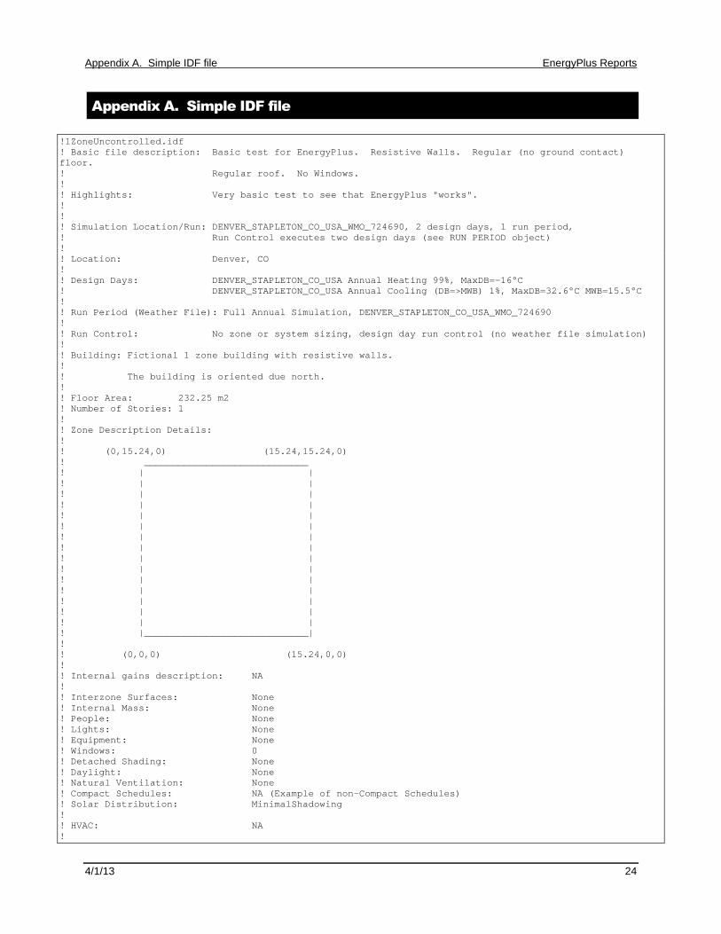
Appendix A. Simple IDF file
!1ZoneUncontrolled.idf! Basic file description: Basic test for EnergyPlus. Resistive Walls. Regular (no ground contact)floor.! Regular roof. No Windows.!! Highlights: Very basic test to see that EnergyPlus "works".!!! Simulation Location/Run: DENVER_STAPLETON_CO_USA_WMO_724690, 2 design days, 1 run period,! Run Control executes two design days (see RUN PERIOD object)!! Location: Denver, CO!! Design Days: DENVER_STAPLETON_CO_USA Annual Heating 99%, MaxDB=-16°C! DENVER_STAPLETON_CO_USA Annual Cooling (DB=>MWB) 1%, MaxDB=32.6°C MWB=15.5°C!! Run Period (Weather File): Full Annual Simulation, DENVER_STAPLETON_CO_USA_WMO_724690!! Run Control: No zone or system sizing, design day run control (no weather file simulation)!! Building: Fictional 1 zone building with resistive walls.!! The building is oriented due north.!! Floor Area: 232.25 m2! Number of Stories: 1!! Zone Description Details:!! (0,15.24,0) (15.24,15.24,0)! _____________________________! | |! | |! | |! | |! | |! | |! | |! | |! | |! | |! | |! | |! | |! | |! | |! |_____________________________|!! (0,0,0) (15.24,0,0)!! Internal gains description: NA!! Interzone Surfaces: None! Internal Mass: None! People: None! Lights: None! Equipment: None! Windows: 0! Detached Shading: None! Daylight: None! Natural Ventilation: None! Compact Schedules: NA (Example of non-Compact Schedules)! Solar Distribution: MinimalShadowing!! HVAC: NA!

Appendix A. Simple IDF file EnergyPlus Reports
4/1/13 25
! Zonal Equipment: NA! Central Air Handling Equipment: No! System Equipment Autosize: No! Purchased Cooling: No! Purchased Heating: No! Purchased Chilled Water: No! Purchased Hot Water: No! Coils: None! Pumps: None! Boilers: None! Chillers: None! Towers: None!! Results:! Standard Reports: Variable Dictionary, Surfaces (dxf-wireframe), Meter File! Timestep or Hourly Variables: Hourly and Daily! Time bins Report: None! HTML Report: None! Environmental Emissions: None! Utility Tariffs: None
Output:PreprocessorMessage,No Preprocessor Used, !- Preprocessor NameInformation, !- Error SeverityIllustrative Message, !- Message Line 1No problems for processing; !- Message Line 2
Version,3.0; !- Version Identifier
Timestep,4; !- Number of Timesteps per Hour
Building,Simple One Zone (Wireframe DXF), !- Name0.0000000E+00, !- North Axis {deg}Suburbs, !- Terrain.04, !- Loads Convergence Tolerance Value.004, !- Temperature Convergence Tolerance Value {deltaC}MinimalShadowing, !- Solar Distribution30; !- Maximum Number of Warmup Days
HeatBalanceAlgorithm,ConductionTransferFunction; !- Algorithm
SurfaceConvectionAlgorithm:Inside,Detailed; !- Algorithm
SurfaceConvectionAlgorithm:Outside,Detailed; !- Algorithm
SimulationControl,No, !- Do Zone Sizing CalculationNo, !- Do System Sizing CalculationNo, !- Do Plant Sizing CalculationYes, !- Run Simulation for Sizing PeriodsYes; !- Run Simulation for Weather File Run Periods
RunPeriod,1, !- Begin Month1, !- Begin Day of Month12, !- End Month31, !- End Day of MonthTuesday, !- Day of Week for Start DayYes, !- Use Weather File Holidays and Special DaysYes, !- Use Weather File Daylight Saving PeriodNo, !- Apply Weekend Holiday RuleYes, !- Use Weather File Rain IndicatorsYes; !- Use Weather File Snow Indicators
Site:Location,

Appendix A. Simple IDF file EnergyPlus Reports
4/1/13 26
DENVER_STAPLETON_CO_USA_WMO_724690, !- Name39.77, !- Latitude {deg}-104.87, !- Longitude {deg}-7.00, !- Time Zone {hr}1611.00; !- Elevation {m}
! WMO=724690 Time Zone=NAM (GMT-07:00) Mountain Time (US & Canada)! Data Source=ASHRAE 2005 Annual Design Conditions! Using Design Conditions from "Climate Design Data 2005 ASHRAE Handbook"! DENVER_STAPLETON_CO_USA Extreme Annual Wind Speeds, 1%=10.9m/s, 2.5%=8.8m/s, 5%=7.7m/s! DENVER_STAPLETON_CO_USA Extreme Annual Temperatures, Max Drybulb=37.2°C Min Drybulb=-24.6°C! DENVER_STAPLETON_CO_USA Annual Heating Design Conditions Wind Speed=2.3m/s Wind Dir=180! Coldest Month=December! DENVER_STAPLETON_CO_USA Annual Heating 99%, MaxDB=-16°C
SizingPeriod:DesignDay,DENVER_STAPLETON Ann Htg 99% Condns DB, !- Name-16, !- Maximum Dry-Bulb Temperature {C}0.0, !- Daily Temperature Range {deltaC}-16, !- Humidity Indicating Conditions at Maximum Dry-Bulb83411., !- Barometric Pressure {Pa}2.3, !- Wind Speed {m/s}180, !- Wind Direction {deg}0.00, !- Sky Clearness0, !- Rain Indicator0, !- Snow Indicator21, !- Day of Month12, !- MonthWinterDesignDay, !- Day Type0, !- Daylight Saving Time IndicatorWetBulb; !- Humidity Indicating Type
! DENVER_STAPLETON Annual Cooling Design Conditions Wind Speed=4m/s Wind Dir=120! Hottest Month=July! DENVER_STAPLETON_CO_USA Annual Cooling (DB=>MWB) 1%, MaxDB=32.6°C MWB=15.5°C
SizingPeriod:DesignDay,DENVER_STAPLETON Ann Clg 1% Condns DB=>MWB, !- Name32.6, !- Maximum Dry-Bulb Temperature {C}15.2, !- Daily Temperature Range {deltaC}15.5, !- Humidity Indicating Conditions at Maximum Dry-Bulb83411., !- Barometric Pressure {Pa}4, !- Wind Speed {m/s}120, !- Wind Direction {deg}1.00, !- Sky Clearness0, !- Rain Indicator0, !- Snow Indicator21, !- Day of Month7, !- MonthSummerDesignDay, !- Day Type0, !- Daylight Saving Time IndicatorWetBulb; !- Humidity Indicating Type
Material:NoMass,R13LAYER, !- NameRough, !- Roughness2.290965, !- Thermal Resistance {m2-K/W}0.9000000, !- Thermal Absorptance0.7500000, !- Solar Absorptance0.7500000; !- Visible Absorptance
Material:NoMass,R31LAYER, !- NameRough, !- Roughness5.456, !- Thermal Resistance {m2-K/W}0.9000000, !- Thermal Absorptance0.7500000, !- Solar Absorptance0.7500000; !- Visible Absorptance
Material,C5 - 4 IN HW CONCRETE, !- Name

Appendix A. Simple IDF file EnergyPlus Reports
4/1/13 27
MediumRough, !- Roughness0.1014984, !- Thickness {m}1.729577, !- Conductivity {W/m-K}2242.585, !- Density {kg/m3}836.8000, !- Specific Heat {J/kg-K}0.9000000, !- Thermal Absorptance0.6500000, !- Solar Absorptance0.6500000; !- Visible Absorptance
Construction,R13WALL, !- NameR13LAYER; !- Outside Layer
Construction,FLOOR, !- NameC5 - 4 IN HW CONCRETE; !- Outside Layer
Construction,ROOF31, !- NameR31LAYER; !- Outside Layer
Site:GroundTemperature:BuildingSurface,18.89, !- January Ground Temperature {C}18.92, !- February Ground Temperature {C}19.02, !- March Ground Temperature {C}19.12, !- April Ground Temperature {C}19.21, !- May Ground Temperature {C}19.23, !- June Ground Temperature {C}19.07, !- July Ground Temperature {C}19.32, !- August Ground Temperature {C}19.09, !- September Ground Temperature {C}19.21, !- October Ground Temperature {C}19.13, !- November Ground Temperature {C}18.96; !- December Ground Temperature {C}
Zone,ZONE ONE, !- Name0.0000000E+00, !- Direction of Relative North {deg}0.0000000E+00, !- X Origin {m}0.0000000E+00, !- Y Origin {m}0.0000000E+00, !- Z Origin {m}1, !- Type1, !- Multiplierautocalculate, !- Ceiling Height {m}autocalculate; !- Volume {m3}
ScheduleTypeLimits,Fraction, !- Name0.0 : 1.0, !- RangeCONTINUOUS; !- Numeric Type
GlobalGeometryRules,UpperLeftCorner, !- Starting Vertex PositionCounterClockWise, !- Vertex Entry DirectionWorldCoordinateSystem; !- Coordinate System
BuildingSurface:Detailed,Zn001:Wall001, !- NameWall, !- Surface TypeR13WALL, !- Construction NameZONE ONE, !- Zone NameOutdoors, !- Outside Boundary Condition, !- Outside Boundary Condition ObjectSunExposed, !- Sun ExposureWindExposed, !- Wind Exposure0.5000000, !- View Factor to Ground4, !- Number of Vertices0.0000000E+00,0.0000000E+00,4.572000, !- X,Y,Z ==> Vertex 10.0000000E+00,0.0000000E+00,0.0000000E+00, !- X,Y,Z ==> Vertex 215.24000,0.0000000E+00,0.0000000E+00, !- X,Y,Z ==> Vertex 315.24000,0.0000000E+00,4.572000; !- X,Y,Z ==> Vertex 4

Appendix A. Simple IDF file EnergyPlus Reports
4/1/13 28
BuildingSurface:Detailed,Zn001:Wall002, !- NameWall, !- Surface TypeR13WALL, !- Construction NameZONE ONE, !- Zone NameOutdoors, !- Outside Boundary Condition, !- Outside Boundary Condition ObjectSunExposed, !- Sun ExposureWindExposed, !- Wind Exposure0.5000000, !- View Factor to Ground4, !- Number of Vertices15.24000,0.0000000E+00,4.572000, !- X,Y,Z ==> Vertex 115.24000,0.0000000E+00,0.0000000E+00, !- X,Y,Z ==> Vertex 215.24000,15.24000,0.0000000E+00, !- X,Y,Z ==> Vertex 315.24000,15.24000,4.572000; !- X,Y,Z ==> Vertex 4
BuildingSurface:Detailed,Zn001:Wall003, !- NameWall, !- Surface TypeR13WALL, !- Construction NameZONE ONE, !- Zone NameOutdoors, !- Outside Boundary Condition, !- Outside Boundary Condition ObjectSunExposed, !- Sun ExposureWindExposed, !- Wind Exposure0.5000000, !- View Factor to Ground4, !- Number of Vertices15.24000,15.24000,4.572000, !- X,Y,Z ==> Vertex 115.24000,15.24000,0.0000000E+00, !- X,Y,Z ==> Vertex 20.0000000E+00,15.24000,0.0000000E+00, !- X,Y,Z ==> Vertex 30.0000000E+00,15.24000,4.572000; !- X,Y,Z ==> Vertex 4
BuildingSurface:Detailed,Zn001:Wall004, !- NameWall, !- Surface TypeR13WALL, !- Construction NameZONE ONE, !- Zone NameOutdoors, !- Outside Boundary Condition, !- Outside Boundary Condition ObjectSunExposed, !- Sun ExposureWindExposed, !- Wind Exposure0.5000000, !- View Factor to Ground4, !- Number of Vertices0.0000000E+00,15.24000,4.572000, !- X,Y,Z ==> Vertex 10.0000000E+00,15.24000,0.0000000E+00, !- X,Y,Z ==> Vertex 20.0000000E+00,0.0000000E+00,0.0000000E+00, !- X,Y,Z ==> Vertex 30.0000000E+00,0.0000000E+00,4.572000; !- X,Y,Z ==> Vertex 4
BuildingSurface:Detailed,Zn001:Flr001, !- NameFloor, !- Surface TypeFLOOR, !- Construction NameZONE ONE, !- Zone NameSurface, !- Outside Boundary ConditionZn001:Flr001, !- Outside Boundary Condition ObjectNoSun, !- Sun ExposureNoWind, !- Wind Exposure1.000000, !- View Factor to Ground4, !- Number of Vertices15.24000,0.000000,0.0, !- X,Y,Z ==> Vertex 10.000000,0.000000,0.0, !- X,Y,Z ==> Vertex 20.000000,15.24000,0.0, !- X,Y,Z ==> Vertex 315.24000,15.24000,0.0; !- X,Y,Z ==> Vertex 4
BuildingSurface:Detailed,Zn001:Roof001, !- NameRoof, !- Surface TypeROOF31, !- Construction NameZONE ONE, !- Zone NameOutdoors, !- Outside Boundary Condition

Appendix A. Simple IDF file EnergyPlus Reports
4/1/13 29
, !- Outside Boundary Condition ObjectSunExposed, !- Sun ExposureWindExposed, !- Wind Exposure0.0000000E+00, !- View Factor to Ground4, !- Number of Vertices0.000000,15.24000,4.572, !- X,Y,Z ==> Vertex 10.000000,0.000000,4.572, !- X,Y,Z ==> Vertex 215.24000,0.000000,4.572, !- X,Y,Z ==> Vertex 315.24000,15.24000,4.572; !- X,Y,Z ==> Vertex 4
Output:Variable,*, !- Key Valueoutdoor dry bulb, !- Variable Namehourly; !- Reporting Frequency
Output:Variable,*, !- Key ValueDaylight Saving Time Indicator, !- Variable Namedaily; !- Reporting Frequency
Output:Variable,*, !- Key ValueDayType Index, !- Variable Namedaily; !- Reporting Frequency
Output:Variable,*, !- Key ValueZone Mean Air Temperature, !- Variable Namehourly; !- Reporting Frequency
Output:Variable,*, !- Key ValueZone Total Internal Latent Gain, !- Variable Namehourly; !- Reporting Frequency
Output:Variable,*, !- Key ValueZone Mean Radiant Temperature, !- Variable Namehourly; !- Reporting Frequency
Output:Variable,*, !- Key ValueZone Air Balance Surface Convection Rate, !- Variable Namehourly; !- Reporting Frequency
Output:Variable,*, !- Key ValueZone Air Balance Air Energy Storage Rate, !- Variable Namehourly; !- Reporting Frequency
Output:Variable,*, !- Key ValueSurface Inside Temperature, !- Variable Namedaily; !- Reporting Frequency
Output:Variable,*, !- Key ValueSurface Outside Temperature, !- Variable Namedaily; !- Reporting Frequency
Output:Variable,*, !- Key ValueSurface Int Convection Coeff, !- Variable Namedaily; !- Reporting Frequency
Output:Variable,*, !- Key ValueSurface Ext Convection Coeff, !- Variable Namedaily; !- Reporting Frequency
Output:Reports,

Appendix A. Simple IDF file EnergyPlus Reports
4/1/13 30
VariableDictionary, !- Type of ReportIDF; !- Report Name
Output:Reports,surfaces, !- Type of Reportdxf:wireframe; !- Report Name
Output:Reports,construction; !- Type of Report
Output:Meter:MeterFileOnly,ExteriorLights:Electricity, !- Namehourly; !- Reporting Frequency
Output:Meter:MeterFileOnly,Carbon Equivalent:Facility, !- Namehourly; !- Reporting Frequency
Output:Meter:MeterFileOnly,EnergyTransfer:Building, !- Namehourly; !- Reporting Frequency
Output:Meter:MeterFileOnly,EnergyTransfer:Facility, !- Namehourly; !- Reporting Frequency
OutputControl:Table:Style,HTML; !- Column Separator
Output:Table:SummaryReports,AllSummary; !- Report 1 Name
Exterior:Lights,ExtLights, !- NameAlwaysOn, !- Schedule Name5250, !- Design Level {W}AstronomicalClock, !- Control OptionGrounds Lights; !- End-Use Subcategory
ScheduleTypeLimits,On/Off, !- Name0:1, !- RangeDISCRETE; !- Numeric Type
Schedule:Day:Hourly,On, !- NameOn/Off, !- Schedule Type Limits Name1., !- Hour 11., !- Hour 21., !- Hour 31., !- Hour 41., !- Hour 51., !- Hour 61., !- Hour 71., !- Hour 81., !- Hour 91., !- Hour 101., !- Hour 111., !- Hour 121., !- Hour 131., !- Hour 141., !- Hour 151., !- Hour 161., !- Hour 171., !- Hour 181., !- Hour 191., !- Hour 201., !- Hour 211., !- Hour 221., !- Hour 231.; !- Hour 24

Appendix A. Simple IDF file EnergyPlus Reports
4/1/13 31
Schedule:Week:Daily,On Weeks, !- NameOn, !- Sunday Schedule:Day NameOn, !- Monday Schedule:Day NameOn, !- Tuesday Schedule:Day NameOn, !- Wednesday Schedule:Day NameOn, !- Thursday Schedule:Day NameOn, !- Friday Schedule:Day NameOn, !- Saturday Schedule:Day NameOn, !- Holiday Schedule:Day NameOn, !- SummerDesignDay Schedule:Day NameOn, !- WinterDesignDay Schedule:Day NameOn, !- CustomDay1 Schedule:Day NameOn; !- CustomDay2 Schedule:Day Name
Schedule:Year,AlwaysOn, !- NameOn/Off, !- Schedule Type Limits NameOn Weeks, !- Schedule:Week Name 11, !- Start Month 11, !- Start Day 112, !- End Month 131; !- End Day 1
Recommended