A Leader in Level Measurement
Series 509-7X Universal III™ Transmitter
with HART® Protocol using 409-1000 Electronics
U.S. and Canada: 1-800-553-909224-Hour Service: 1-800-527-6297International: +1 215-674-1234Fax: +1 215-674-2731E-mail: [email protected] Website: www.drexelbrook.com
Installation andOperating Instructions
For Assistance Call 1-800-527-6297Outside North America + 215-674-1234

AMETEK Drexelbrook makes no warranty of any kind with regard to the material contained in this manual, including, but not limited to, implied warranties or fitness for a particular purpose. Drexelbrook shall not be liable for errors contained herein or for incidental or consequential damages in connection with the performance or use of material.
© Copyright AMETEK Drexelbrook

Series 509-7X Universal III™ Transmitter
with HART® Protocol using 409-1000 Electronics
EDO# 02-08-101409-1000-000-LMIssue #10
205 Keith Valley Road, Horsham, PA 19044 U.S. and Canada: 1-800-553-909224-Hour Service: 1-800-527-6297International: +1 215-674-1234Fax: +1 215-674-2731E-mail: [email protected] Website: www.drexelbrook.com
An ISO 9001 Certified Company
Form 440-0001-001 3/1/2006
TERMS AND CONDITIONS OF SALEGENERAL: ALL ORDERS ARE SUBJECT TO THE FOLLOWING TERMS AND CONDITIONS. ANY ACCEPTANCE OF ANY OFFER OF BUYER FOR ANY GOODS OR SERVICES IS CONDITIONED UPON THESE TERMS AND CONDITIONS, AND SELLER OBJECTS TO ANY ADDITIONAL OR DIFFERENT TERMS PROPOSED BY BUYER IN ANY DOCUMENT, WHICH SHALL NOT BE BINDING UPON SELLER. No salesman or other party is authorized to bind the AMETEK DREXELBROOK Division of AMETEK, Inc. (hereinafter “Seller”) by any agreement, warranty, statement, promise, or understanding not herein expressed, and no modifications shall be binding on Seller unless the same are in writing and signed by an executive officer of Seller or his or her duly authorized representative. Verbal orders shall not be executed until written notification has been received and acknowledged by Seller.
QUOTATIONS: Written quotations are valid for thirty (30) days unless otherwise stated. Verbal quotations expire the same day they are made.
PRICES: All prices and terms are subject to change without notice. Buyer-requested changes to its order (“Orders”), including those affecting the identity, scope and delivery of the goods or services, must be documented in writing and are subject to Seller’s prior approval and adjustments in price, schedule and other affected terms and conditions. Orders requiring certified test data in excess of commercial requirements, are subject to a special charge.
ORDER ACCEPTANCE: All Orders are subject to final approval and acceptance by Seller at its office located at 205 Keith Valley Road, Horsham, Pennsylvania 19044.
TERMS OF PAYMENT: Seller’s standard terms of payment for Buyers who qualify for credit are net thirty (30) days from date of invoice. All invoices must be paid in United States dollars.
CREDIT: Seller reserves the right at any time to revoke any credit extended to Buyer or otherwise modify terms of payment if Buyer fails to pay for any shipments when due or if in Seller’s opinion there is a material adverse change in Buyer’s financial condition. Seller may, at its option, cancel any accepted Order if Buyer fails to pay any invoices when due.
DELIVERY: Shipments are F.O.B place of manufacture (“Shipping Point”) and the Buyer shall pay all freight, transportation, shipping, duties, fees, handling, insurance, storage, demurrage, or similar charges from Shipping Point. Delivery of goods to common carrier shall constitute delivery and passing of title to the Buyer, and all risk of loss or damage in transit shall be borne by Buyer. Any claims or losses for damage or destruction after such delivery shall be the responsibility of Buyer.
Seller reserves the right to make delivery in installments which shall be separately invoiced and paid for when due, without regard to subsequent deliveries. Delay in delivery of any installment shall not relieve Buyer of its obligation to accept remaining deliveries.
Acknowledged shipping dates are approximate only and based on prompt receipt of all necessary information from Buyer and Buyer’s compliance with terms of payment.
TAXES: All sales, excise and similar taxes which Seller may be required to pay or collect with respect to the goods and/or services covered by any Order, shall be for the account of the Buyer except as otherwise provided by law or unless specifically stated otherwise by Seller in writing.
TERMINATION AND HOLD ORDERS: No Order may be terminated by Buyer except upon written request by Buyer and approval by Seller, and if said request is approved by Seller, under the following conditions: (1) Buyer agrees to accept delivery of all of the units completed by Seller through the workday on which Seller receives the written termination request; (2) Buyer agrees to pay to Seller all direct costs and expenses applicable to the portion of the Order that is incomplete.
WARRANTY: A. Hardware: Seller warrants its goods against defects in materials and workmanship under normal use and service for one (1) year from the date of invoice. B. Software and Firmware: Unless otherwise specified, Seller warrants for a period of one (1) year from date of invoice that standard software or firmware, when used with Seller specified hardware, shall perform in accordance with Seller’s published specifications. Seller makes no representation or warranty, expressed or implied, that the operation of the software or firmware shall be uninterrupted or error-free, or that functions contained therein shall meet or satisfy the Buyer’s intended use or requirements. C. Services: Seller warrants that services, including engineering and custom application, whether provided on a fixed cost or time and material basis, shall be performed in accordance with generally accepted industry practices. D. Remedies: Seller’s liability under this section is restricted to replacing, repairing, or issuing credit (at Seller’s option) for any returned goods and only under the following conditions: (1) Seller must be promptly notified, in writing, as soon as possible after the defects have been noted by the Buyer, but not later than (1) year from date of invoice from Seller; (2) The defective goods are to be returned to the place of manufacture, shipping charges prepaid by the Buyer; (3) Seller’s inspection shall disclose to its satisfaction that the goods were defective in materials or workmanship at the time of shipment; (4) Any warranty service (consisting of time, travel and expenses related to such services) performed other than at Seller’s factory, shall be at Buyer’s expense. E.Repaired/Reconditioned Goods: As to out-of-warranty goods which Seller has repaired or reconditioned, Seller warrants for a period of sixty (60) days from date of its invoice only new components replaced in the most recent repair/reconditioning. F. Returns and Adjustments: No goods may be returned unless authorized in advance by Seller and then only upon such conditions to which Seller may agree. Buyer must obtain an RMA (Return Material Authorization) number from Seller prior to any return shipment and such RMA number must appear on the shipping label and packing slip. Buyer shall be responsible for the returned goods until such time as Seller receives the same at its plant and for all charges for packing, inspection, shipping, transportation, or insurance associated with returned goods. In the event that credit for returned goods is granted, it shall be at the lesser of the then current prices or the original purchase price. Claims for shortage or incorrect material must be made within five (5) days after receipt of shipment.
ALL OTHER WARRANTIES, FOR ANY OF SELLER’S GOODS OR SERVICES, WHETHER ORAL, WRITTEN, EXPRESS, IMPLIED, STATUTORY OR OTHERWISE, INCLUDING WITHOUT LIMITATION ANY IMPLIED WARRANTY OF MERCHANTABILITY OR FITNESS FOR PURPOSE ARE EXCLUDED.
INTELLECTUAL PROPERTY: Seller’s sale of goods or provision of related documentation or other materials to Buyer shall not transfer any intellectual property rights to Buyer unless Seller specifically agrees to do so in writing. Seller shall retain ownership of all applicable patents, trademarks, copyrights and other intellectual property rights. Buyer shall not use, copy or transfer any such items in violation of Seller’s intellectual property rights or applicable law, or for any purposes other than that for which the items were furnished.
Seller shall defend any lawsuit brought against the Buyer based on a claim that the design or construction of the goods sold hereunder by Seller infringe any United States or Canadian Patent, Copyright or Mask Work Registration, provided that Buyer promptly notifies Seller of such claim in writing and further provided that, at Seller’s expense, (1) Buyer gives Seller the sole right to defend or control the defense of the suit or proceeding, including settlement, and (2) Buyer provides all necessary information and assistance for that defense. In the event of a charge of infringement, Seller’s obligation under the agreement shall be fulfilled if Seller, at its option and expense, either (i) settles such claim; (ii) procures for Buyer the right to continue using such goods; (iii) replaces or modifies goods to avoid infringement; or (iv) accepts the return of any infringing goods and refunds their purchase price; or (iv) defends against such claim.
If Buyer furnishes specifications or designs to Seller, the obligations of Seller set forth above shall not apply to goods made by Seller using such specifications or designs, and Buyer shall defend, indemnify and hold Seller harmless against any third party claims for infringement which arise out of Seller’s use of specifications or designs furnished by Buyer.
SOFTWARE LICENSE: If goods purchased hereunder include software (“Software”), Buyer may use the Software only as part of the goods. Buyer may not use, copy, or transfer any of the Software except as may be permitted under the applicable License Agreement provided with the goods. Buyer’s right to use, copy or transfer the Software shall terminate upon termination of Buyer’s right to use the goods.
PACKAGING/WEIGHTS AND DIMENSIONS: Buyer specified packing or marking may be subject to additional charges not otherwise included in the price of the goods. Published weights and dimensions are estimates or approximate only and are not warranted.
FORCE MAJEURE: Seller shall not be responsible for delays in delivery or any failure to deliver due to causes beyond Seller’s control, including but not limited to the following items: acts of God, war, terrorism, mobilization, civil commotion, riots, embargoes, domestic or foreign governmental regulations or orders, governmental priorities, port congestion, acts of the Buyer, its agents or employees, fires, floods, strikes, lockouts and other labor difficulties, shortages of or inability to obtain shipping space or transportation, inability to secure fuel, supplies or power at current prices or on account of shortages thereof, or due to limitations imposed by the extent of availability of Seller’s normal manufacturing facilities.
If a delay excused per the above extends for more than ninety (90) days and the parties have not agreed upon a revised basis for continuing providing the goods or services at the end of the delay, including adjustment of the price, then Buyer, upon thirty (30) days’ prior written notice to Seller may terminate the Order with respect to the unexecuted portion of the goods or services, whereupon Buyer shall promptly pay Seller its reasonable termination charges upon submission of Seller’s invoices thereof.
LIMITATION OF LIABILITY: Seller’s liability for any claim of any kind, except infringement of intellectual property rights, shall not exceed the purchase price of any goods or services which give rise to the claim. SELLER SHALL IN NO EVENT BE LIABLE FOR BUYER’S MANUFACTURING COSTS, LOST PROFITS, LOSS OF USE OF THE GOODS OR SERVICES, COST OF CAPITAL, COST OF SUBSTITUTE GOODS, FACILITIES, SERVICES OR REPLACEMENT POWER, DOWNTIME COSTS, CLAIMS OF BUYER’S CUSTOMERS FOR DAMAGES, OR OTHER SPECIAL, PROXIMATE, INCIDENTAL, INDIRECT, EXEMPLARY OR CONSEQUENTIAL DAMAGES. Any action against Seller must be brought within eighteen (18) months after the cause of action accrues. These disclaimers and limitations of liability shall apply regardless of the form of action, whether in contract, tort or otherwise, and further shall extend to the benefit of Seller’s vendors, appointed distributors and other authorized resellers as third-party beneficiaries.
PROHIBITION FOR HAZARDOUS USE: Goods sold hereunder generally are not intended for application in and shall not be used by Buyer in the construction or operation of a nuclear installation or in connection with the use or handling of nuclear material, or for any hazardous activity or critical application, where failure of a single component could cause substantial harm to persons or property, unless the goods have been specifically approved for such a use or application. Seller disclaims all liability for any loss or damage resulting from such unauthorized use and Buyer shall defend, indemnify and hold harmless the Seller against any such liability, whether as a result of breach of contract, warranty, tort (regardless of the degree of fault or negligence), strict liability or otherwise.
EXPORT CONTROL: Buyer shall comply with all export control laws and regulations of the United States, and all sales hereunder are subject to those laws and regulations. Seller shall not be named as shipper or exporter of record for any goods sold hereunder unless specifically agreed to in writing by Seller. At Seller’s request, Buyer shall furnish Seller with end-use and end-user information to determine export license applicability. Buyer warrants, in accordance with U.S. Export Law, that goods sold hereunder shall not be destined for facilities or activities involving nuclear, chemical or biological weapons, or related missile delivery systems in named prohibited regions or countries.
GOVERNING LAW: Seller intends to comply with all laws applicable to its performance under any order. All matters relating to interpretation and effect of these terms and any authorized changes, modifications or amendments thereto shall be governed by the laws of the Commonwealth of Pennsylvania. No government contract regulations or clauses shall apply to the goods or services, this agreement, or act to bind Seller unless specifically agreed to by Seller in writing.
NON-WAIVER BY SELLER: Waiver by Seller of a breach of any of these terms and conditions shall not be construed as a waiver of any other breach.
SEVERABILITY AND ENTIRE AGREEMENT: If any provision of these terms and conditions is unenforceable, the remaining terms shall nonetheless continue in full force and effect. This writing, together with any other terms and conditions Seller specifically agrees to in writing, constitutes the entire terms and conditions of sale between Buyer and Seller and supercedes any and all prior discussions, and negotiations on its subject matter.
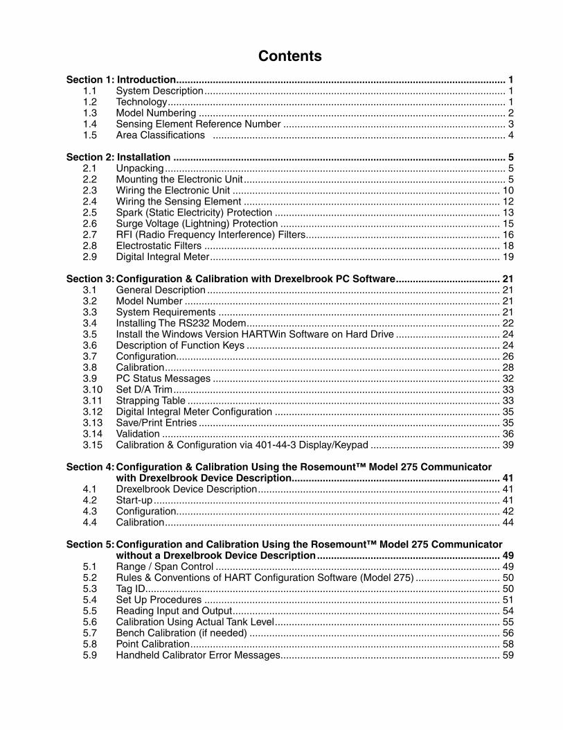
Contents
Section 1: Introduction ..................................................................................................................... 1 1.1 System Description ........................................................................................................... 1 1.2 Technology ........................................................................................................................ 1 1.3 Model Numbering ............................................................................................................. 2 1.4 Sensing Element Reference Number ............................................................................... 3 1.5 Area Classifications ........................................................................................................ 4
Section 2: Installation ...................................................................................................................... 5 2.1 Unpacking ......................................................................................................................... 5 2.2 Mounting the Electronic Unit ............................................................................................. 5 2.3 Wiring the Electronic Unit ............................................................................................... 10 2.4 Wiring the Sensing Element ........................................................................................... 12 2.5 Spark (Static Electricity) Protection ................................................................................ 13 2.6 Surge Voltage (Lightning) Protection .............................................................................. 15 2.7 RFI (Radio Frequency Interference) Filters ..................................................................... 16 2.8 Electrostatic Filters ......................................................................................................... 18 2.9 Digital Integral Meter ....................................................................................................... 19
Section 3: Configuration & Calibration with Drexelbrook PC Software ..................................... 21 3.1 General Description ........................................................................................................ 21 3.2 Model Number ................................................................................................................ 21 3.3 System Requirements .................................................................................................... 21 3.4 Installing The RS232 Modem .......................................................................................... 22 3.5 Install the Windows Version HARTWin Software on Hard Drive ..................................... 24 3.6 Description of Function Keys .......................................................................................... 24 3.7 Configuration................................................................................................................... 26 3.8 Calibration ....................................................................................................................... 28 3.9 PC Status Messages ...................................................................................................... 32 3.10 Set D/A Trim .................................................................................................................... 33 3.11 Strapping Table ............................................................................................................... 33 3.12 Digital Integral Meter Configuration ................................................................................ 35 3.13 Save/Print Entries ........................................................................................................... 35 3.14 Validation ........................................................................................................................ 36 3.15 Calibration & Configuration via 401-44-3 Display/Keypad .............................................. 39
Section 4: Configuration & Calibration Using the Rosemount™ Model 275 Communicator with Drexelbrook Device Description.......................................................................... 41 4.1 Drexelbrook Device Description ...................................................................................... 41 4.2 Start-up ........................................................................................................................... 41 4.3 Configuration................................................................................................................... 42 4.4 Calibration ....................................................................................................................... 44
Section 5: Configuration and Calibration Using the Rosemount™ Model 275 Communicator without a Drexelbrook Device Description ................................................................. 49 5.1 Range / Span Control ..................................................................................................... 49 5.2 Rules & Conventions of HART Configuration Software (Model 275) .............................. 50 5.3 Tag ID.............................................................................................................................. 50 5.4 Set Up Procedures ......................................................................................................... 51 5.5 Reading Input and Output ............................................................................................... 54 5.6 Calibration Using Actual Tank Level ................................................................................ 55 5.7 Bench Calibration (if needed) ......................................................................................... 56 5.8 Point Calibration .............................................................................................................. 58 5.9 Handheld Calibrator Error Messages .............................................................................. 59
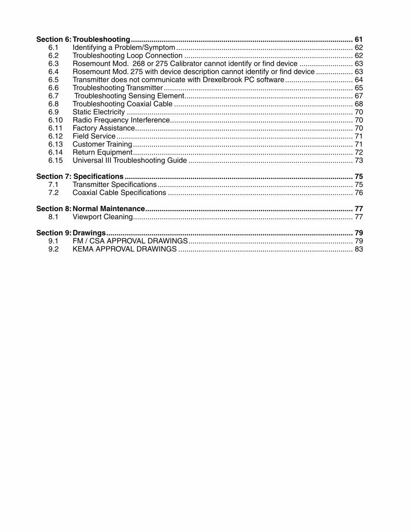
Section 6: Troubleshooting ............................................................................................................ 61 6.1 Identifying a Problem/Symptom ...................................................................................... 62 6.2 Troubleshooting Loop Connection .................................................................................. 62 6.3 Rosemount Mod. 268 or 275 Calibrator cannot identify or find device .......................... 63 6.4 Rosemount Mod. 275 with device description cannot identify or find device .................. 63 6.5 Transmitter does not communicate with Drexelbrook PC software ................................. 64 6.6 Troubleshooting Transmitter ............................................................................................ 65 6.7 Troubleshooting Sensing Element .................................................................................. 67 6.8 Troubleshooting Coaxial Cable ....................................................................................... 68 6.9 Static Electricity .............................................................................................................. 70 6.10 Radio Frequency Interference ......................................................................................... 70 6.11 Factory Assistance .......................................................................................................... 70 6.12 Field Service ................................................................................................................... 71 6.13 Customer Training ........................................................................................................... 71 6.14 Return Equipment ........................................................................................................... 72 6.15 Universal III Troubleshooting Guide ................................................................................ 73
Section 7: Specifications ............................................................................................................... 75 7.1 Transmitter Specifications ............................................................................................... 75 7.2 Coaxial Cable Specifications .......................................................................................... 76
Section 8: Normal Maintenance ..................................................................................................... 77 8.1 Viewport Cleaning ........................................................................................................... 77
Section 9: Drawings ........................................................................................................................ 79 9.1 FM / CSA APPROVAL DRAWINGS ................................................................................ 79 9.2 KEMA APPROVAL DRAWINGS ..................................................................................... 83
Introduction
Section 1: Introduction1.1 System Description The instructions in this manual are for the Drexelbrook
509-7X-XXXSeriesUniversalIII™forlevelmeasurementinliquids,slurries,interfacesandgranulars.
Each Drexelbrook 509-7X-XXX system consists of aUniversal III™ (409-1000) series two-wire, 4-20 mAelectronicunitanda700seriessensingelement(probe).A380seriesconnectingcableisalsosuppliedforconnectionofthesensingelementtotheelectronicunit.
The509-7X-XXX isanadmittance-to-current transducer.Achangeinlevelproducesachangeinadmittancewhichresults in a change of current. It is termed a two-wiretransmitterbecausethesametwowiresthatareusedtopowertheunitalsoindicatethechangeinlevel(4-20mA).
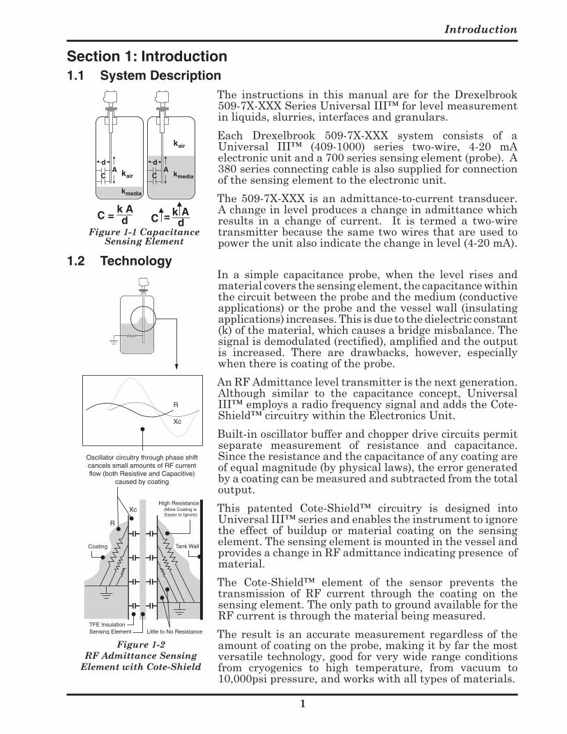
1.2 Technology In a simple capacitance probe, when the level rises and
materialcoversthesensingelement,thecapacitancewithinthecircuitbetweentheprobeandthemedium(conductiveapplications)ortheprobeandthevesselwall(insulatingapplications)increases.Thisisduetothedielectricconstant(k)ofthematerial,whichcausesabridgemisbalance.Thesignal is demodulated (rectified), amplified and the output is increased. There are drawbacks, however, especiallywhenthereiscoatingoftheprobe.
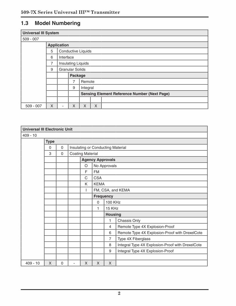
AnRFAdmittanceleveltransmitteristhenextgeneration.Although similar to the capacitance concept, UniversalIII™employsaradiofrequencysignalandaddstheCote-Shield™circuitrywithintheElectronicsUnit.
Built-inoscillatorbufferandchopperdrivecircuitspermitseparate measurement of resistance and capacitance.Sincetheresistanceandthecapacitanceofanycoatingareofequalmagnitude(byphysicallaws),theerrorgeneratedbyacoatingcanbemeasuredandsubtractedfromthetotaloutput.
This patented Cote-Shield™ circuitry is designed intoUniversalIII™seriesandenablestheinstrumenttoignorethe effect of buildup or material coating on the sensingelement.ThesensingelementismountedinthevesselandprovidesachangeinRFadmittanceindicatingpresenceofmaterial.
The Cote-Shield™ element of the sensor prevents thetransmission of RF current through the coating on thesensingelement.TheonlypathtogroundavailablefortheRFcurrentisthroughthematerialbeingmeasured.
Theresult isanaccuratemeasurementregardlessof theamountofcoatingontheprobe,makingitbyfarthemostversatile technology,good forverywiderangeconditionsfrom cryogenics to high temperature, from vacuum to10,000psipressure,andworkswithalltypesofmaterials.
Figure 1-1 Capacitance Sensing Element
k air
Ad
C kmedia
C = k Ad
C =k Ad
A k air
d
C
kmedia
Tank WallCoating
High Resistance
Little to No ResistanceTFE InsulationSensing Element
(More Coating is Easier to Ignore)
R
Xc
Xc
R
Oscillator circuitry through phase shift cancels small amounts of RF current flow (both Resistive and Capacitive)
caused by coating
Figure 1-2 RF Admittance Sensing
Element with Cote-Shield
509-7X Series Universal III™ Transmitter
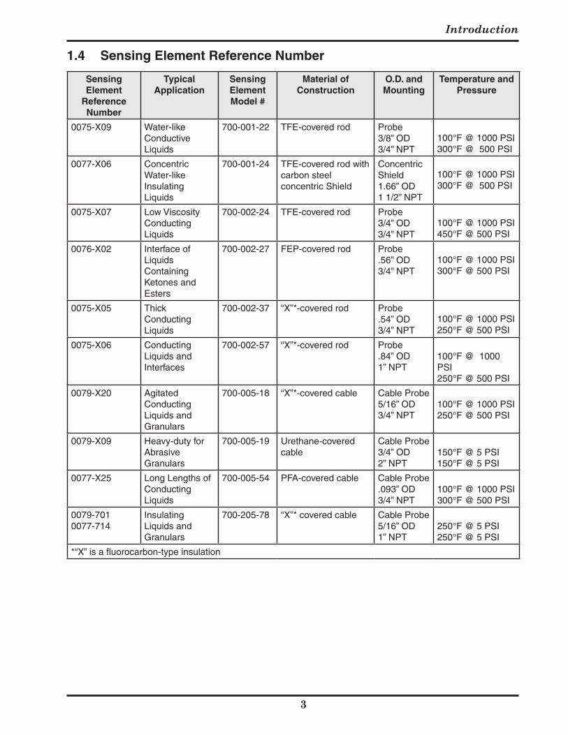
1.3 Model Numbering
Universal III System
509 - 007
Application
5 Conductive Liquids
6 Interface
7 Insulating Liquids
9 Granular Solids
Package
7 Remote
9 Integral
Sensing Element Reference Number (Next Page)
509 - 007 X - X X X
Universal III Electronic Unit
409 - 10
Type
0 0 Insulating or Conducting Material
3 0 Coating Material
Agency Approvals
O No Approvals
F FM
C CSA
K KEMA
I FM, CSA, and KEMA
Frequency
0 100 KHz
1 15 KHz
Housing
1 Chassis Only
4 Remote Type 4X Explosion-Proof
6 Remote Type 4X Explosion-Proof with DrexelCote
7 Type 4X Fiberglass
8 Integral Type 4X Explosion-Proof with DrexelCote
9 Integral Type 4X Explosion-Proof
409 - 10 X 0 - X X X
Introduction
Sensing Element
Reference Number
Typical Application
Sensing Element Model #
Material of Construction
O.D. and Mounting
Temperature and Pressure
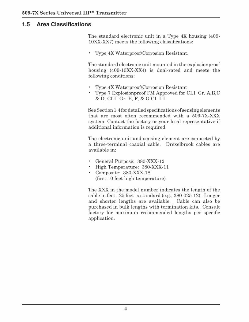
0075-X09 Water-like Conductive Liquids
700-001-22 TFE-covered rod Probe3/8” OD3/4” NPT
100°F @ 1000 PSI300°F @ 500 PSI
0077-X06 Concentric Water-like Insulating Liquids
700-001-24 TFE-covered rod with carbon steel concentric Shield
Concentric Shield1.66” OD1 1/2” NPT
100°F @ 1000 PSI300°F @ 500 PSI
0075-X07 Low Viscosity Conducting Liquids
700-002-24 TFE-covered rod Probe3/4” OD 3/4” NPT
100°F @ 1000 PSI450°F @ 500 PSI
0076-X02 Interface of Liquids Containing Ketones and Esters
700-002-27 FEP-covered rod Probe.56” OD3/4” NPT
100°F @ 1000 PSI300°F @ 500 PSI
0075-X05 Thick Conducting Liquids
700-002-37 “X”*-covered rod Probe.54” OD3/4” NPT
100°F @ 1000 PSI250°F @ 500 PSI
0075-X06 Conducting Liquids and Interfaces
700-002-57 “X”*-covered rod Probe .84” OD1” NPT
100°F @ 1000 PSI250°F @ 500 PSI
0079-X20 Agitated Conducting Liquids and Granulars
700-005-18 “X”*-covered cable Cable Probe5/16” OD3/4” NPT
100°F @ 1000 PSI250°F @ 500 PSI
0079-X09 Heavy-duty for Abrasive Granulars
700-005-19 Urethane-covered cable
Cable Probe3/4” OD2” NPT
150°F @ 5 PSI150°F @ 5 PSI
0077-X25 Long Lengths of Conducting Liquids
700-005-54 PFA-covered cable Cable Probe.093” OD3/4” NPT
100°F @ 1000 PSI300°F @ 500 PSI
0079-701 0077-714
Insulating Liquids and Granulars
700-205-78 “X”* covered cable Cable Probe5/16” OD1” NPT
250°F @ 5 PSI250°F @ 5 PSI
*“X” is a fluorocarbon-type insulation
1.4 Sensing Element Reference Number
509-7X Series Universal III™ Transmitter
1.5 Area Classifications Thestandardelectronicunit inaType4Xhousing (409-
10XX-XX7) meets the following classifications:
• Type4XWaterproof/CorrosionResistant.
Thestandardelectronicunitmountedintheexplosionproofhousing (409-10XX-XX4) is dual-rated and meets thefollowing conditions:
• Type4XWaterproof/CorrosionResistant• Type7ExplosionproofFMApprovedforCI.IGr.A,B,C
&D,CI.IIGr.E,F,&GCI.III.
See Section 1.4 for detailed specifications of sensing elements that are most often recommended with a 509-7X-XXXsystem.Contactthefactoryoryourlocalrepresentativeifadditionalinformationisrequired.
Theelectronicunitandsensingelementareconnectedbya three-terminal coaxial cable. Drexelbrook cables areavailable in:
• General Purpose: 380-XXX-12• High Temperature: 380-XXX-11• Composite: 380-XXX-18 (first 10 feet high temperature)
TheXXXinthemodelnumberindicatesthelengthofthecableinfeet.25feetisstandard(e.g.,380-025-12).Longerand shorter lengths are available. Cable can also bepurchasedinbulklengthswithterminationkits.Consultfactory for maximum recommended lengths per specific application.
Installation
5
Section 2: Installation
2.1 Unpacking
Carefullyremovethecontentsofthecartonandcheckeachitemagainstthepackinglistbeforedestroyinganypackingmaterial. If there is any shortage or damage, report itimmediatelytothefactory.
2.2 Mounting the Electronic Unit
Carefullyremovethecontentsofthecartonandcheckeachitemagainstthepackinglistbeforedestroyinganypackingmaterial. If there is any shortage or damage, report itimmediatelytothefactory.
TheUniversalIIITM(409-1000)Seriessystemwasdesignedfor field mounting, but it should be mounted in a location as freeaspossiblefromvibration,corrosiveatmospheres,andanypossibilityofmechanicaldamage.Forconvenienceatstart-up,mounttheinstrumentinareasonablyaccessiblelocation.Ambienttemperaturesshouldbebetween–40°Fand185°F(–40°Cand85°C).
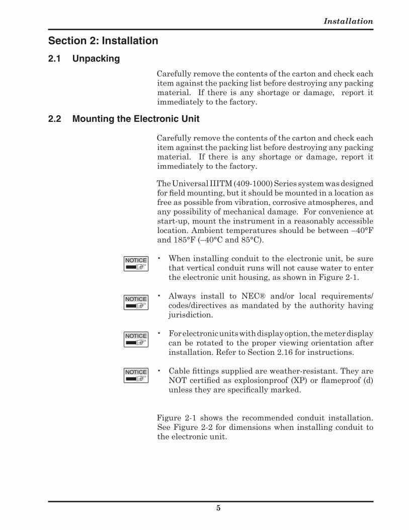
• Wheninstallingconduittotheelectronicunit,besurethatverticalconduitrunswillnotcausewatertoentertheelectronicunithousing,asshowninFigure2-1.
• Always install to NEC® and/or local requirements/codes/directivesasmandatedby theauthorityhavingjurisdiction.
• Forelectronicunitswithdisplayoption,themeterdisplaycanberotatedtotheproperviewingorientationafterinstallation.RefertoSection2.16forinstructions.
• Cable fittings supplied are weather-resistant. They are NOT certified as explosionproof (XP) or flameproof (d) unless they are specifically marked.
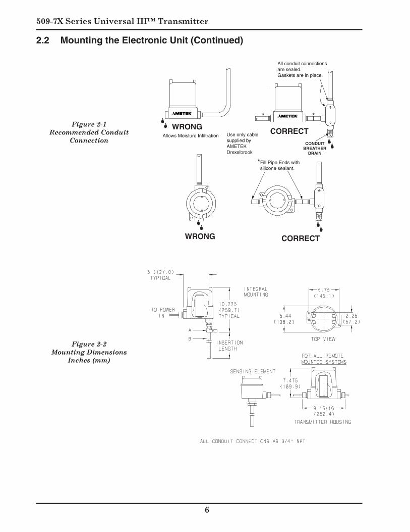
Figure 2-1 shows the recommended conduit installation.SeeFigure2-2fordimensionswheninstallingconduittotheelectronicunit.
509-7X Series Universal III™ Transmitter
Figure 2-2 Mounting Dimensions
Inches (mm)
2.2 Mounting the Electronic Unit (Continued)
Figure 2-1 Recommended Conduit
Connection
WRONG CORRECTCONDUIT
BREATHERDRAIN
WRONG CORRECT
* *
Allows Moisture Infiltration Use only cable supplied byAMETEK Drexelbrook
All conduit connections are sealed. Gaskets are in place.
Fill Pipe Ends with silicone sealant.
CONDULETPacking Gland AssemblyDo Not Disturb!
Hold here while tightening condulet.
Hold here to install or remove sensing element from vessel.
*
Installation
7
2.2 Mounting the Electronic Unit (Continued) Themounting location for thesensingelement (probe) is
oftendeterminedbywhether there isa suitable locationinsideavessel.Anexternalsidearmorstillingwellcanbeconsidered.
Thefollowingsensingelementmountingandinstallationinstructionsshouldbefollowedsothattheequipmentwilloperate properly and accurately:
A. Inapplicationsrequiringaninsulatedsensingelement,useparticularcareduringinstallation.Thereisalwaysthedangerofpuncturingtheinsulation,especiallywiththethin-walledprobes.
B. Sensingelementsshouldbemountedinsuchamannerthat they are not in the direct stream of a filling nozzle or chute. If this is not possible, a deflecting baffle should be installed between the probe and the fill.
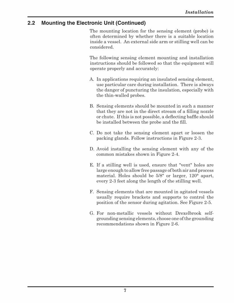
C. Do not take the sensing element apart or loosen thepackingglands.FollowinstructionsinFigure2-3.
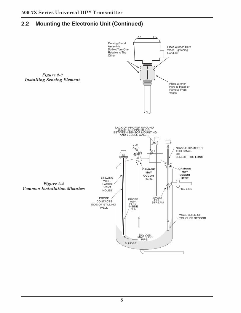
D. Avoid installing the sensing element with any of thecommonmistakesshowninFigure2-4.
E. Ifa stillingwell isused, ensure that "vent"holesarelargeenoughtoallowfreepassageofbothairandprocessmaterial. Holes should be 5/8" or larger, 120° apart,every2-3feetalongthelengthofthestillingwell.
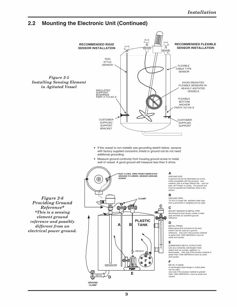
F. Sensingelementsthataremountedinagitatedvesselsusually require brackets and supports to control thepositionofthesensorduringagitation.SeeFigure2-5.
G. For non-metallic vessels without Drexelbrook self-groundingsensingelements,chooseoneofthegroundingrecommendationsshowninFigure2-6.
509-7X Series Universal III™ Transmitter
Figure 2-4 Common Installation Mistakes
PROBE CONTACTS
SIDE OF STILLINGWELL
SLUDGE
SLUDGEMAY CLOG
PIPE
LACK OF PROPER GROUND(EARTH) CONNECTION
BETWEEN SENSOR MOUNTINGAND VESSEL WALL
NOZZLE DIAMETER TOO SMALL OR LENGTH TOO LONG
DAMAGEMAY
OCCURHERE
DAMAGEMAY
OCCURHERE
PROBEMAYFLEX
INSIDEPIPE
FILL LINE
AVOIDFILL
STREAM
WALL BUILD-UPTOUCHES SENSOR
STILLINGWELL
LACKSVENT
HOLES
Figure 2-3Installing Sensing Element
Packing Gland AssemblyDo Not Turn One Relative to The Other
Place Wrench Here When Tightening Condulet
Place Wrench Here to Install or Remove From Vessel
2.2 Mounting the Electronic Unit (Continued)
Installation
9
FLEXIBLEBOTTOMANCHOR
PART# 727-XX-X
CUSTOMERSUPPLIEDSUPPORT
RECOMMENDED FLEXIBLESENSOR INSTALLATION
FLEXIBLECABLE TYPE
SENSOR
RODSTYLE
SENSOR
CUSTOMERSUPPLIEDSUPPORTBRACKET
INSULATEDSUPPORTBUSHINGSPART # 713-XX-X
RECOMMENDED RIGIDSENSOR INSTALLATION
AVOID WEIGHTEDFLEXIBLE SENSORS IN
HEAVILY AGITATEDVESSELS
Figure 2-5 Installing Sensing Element
in Agitated Vessel
Figure 2-6 Providing Ground
Reference**This is a sensing element ground
reference and possibly different from an
electrical power ground.
GROUNDCLAMP
CLAMP
RUN 14 AWG. WIRE FROM FABRICATEDGROUND TO GREEN SENSOR GROUNDSCREW
PLASTICTANK
SENSOR
A B
C
ED
PUMP
WEIGHT
F
METAL
CMOUNT SENSOR IN METAL PIPEMounting the level sensor inside a metalpipe provides an excellent groundreference.
Use only if the process material isgreter than 1000 uMHOS/cm such as acidsand caustic.
AGROUND RODA ground rod can be fabricated out of anymetal compatible with the process. Usematerial that is at least 3/8inch dia. such aspipe, All-Thread, or tubing. The ground rodmust be parallel and relatively close to thesensor.
BGROUND WIRE1/4 inch or larger dia. stainless steel ropethat is anchored or weighted can be used.
ESUBMERGED METAL STRUCTUREUse any constantly submerged metalobject such as: pumps, agitators, orthermowells.
FMETAL FLANGEA submerged metal flange or orifice platecan be used.Use only if the process material is greaterthatn 1000 uMHOS/Cm. such as acids andcaustic.
DMETAL PIPINGMetal piping that connects to the tankbottom can be used as a groundreference. Use only if the process materialis greter than 1000 uMHOS/cm such asacids and caustic.
If the vessel is non metallic see grounding sketch below. sensorswith factory supplied concentric shield or ground rod do not needadditional grounding.
Measure ground continuity from housing ground screw to metalwall of vessel. A good ground will measure less than 5 ohms.
2.2 Mounting the Electronic Unit (Continued)
509-7X Series Universal III™ Transmitter
0
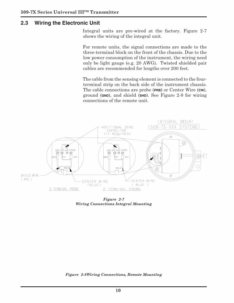
Figure 2-7Wiring Connections Integral Mounting
Figure 2-8Wiring Connections, Remote Mounting
2.3 Wiring the Electronic Unit Integral units are pre-wired at the factory. Figure 2-7
showsthewiringoftheintegralunit.
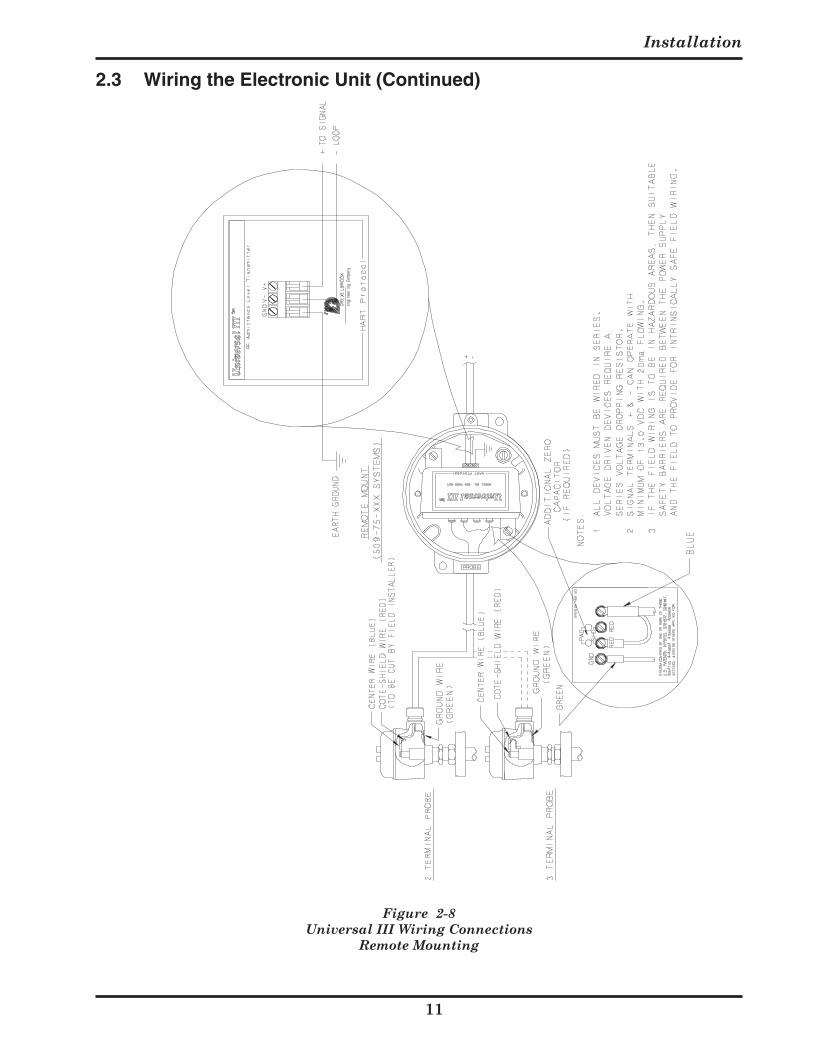
Forremoteunits,thesignalconnectionsaremadetothethree-terminalblockonthefrontofthechassis.Duetothelowpowerconsumptionoftheinstrument,thewiringneedonlybelightgauge(e.g.20AWG).Twistedshieldedpaircablesarerecommendedforlengthsover200feet.
Thecablefromthesensingelementisconnectedtothefour-terminalstriponthebacksideoftheinstrumentchassis.Thecableconnectionsareprobe(prb)orCenterWire(cw),ground (gnd), and shield (shd). See Figure 2-8 for wiringconnectionsoftheremoteunit.
Installation
Figure 2-8Universal III Wiring Connections
Remote Mounting
2.3 Wiring the Electronic Unit (Continued)
509-7X Series Universal III™ Transmitter
2.4 Wiring the Sensing Element CAUTION ! Before using Intrinsic Safety Barriers, read
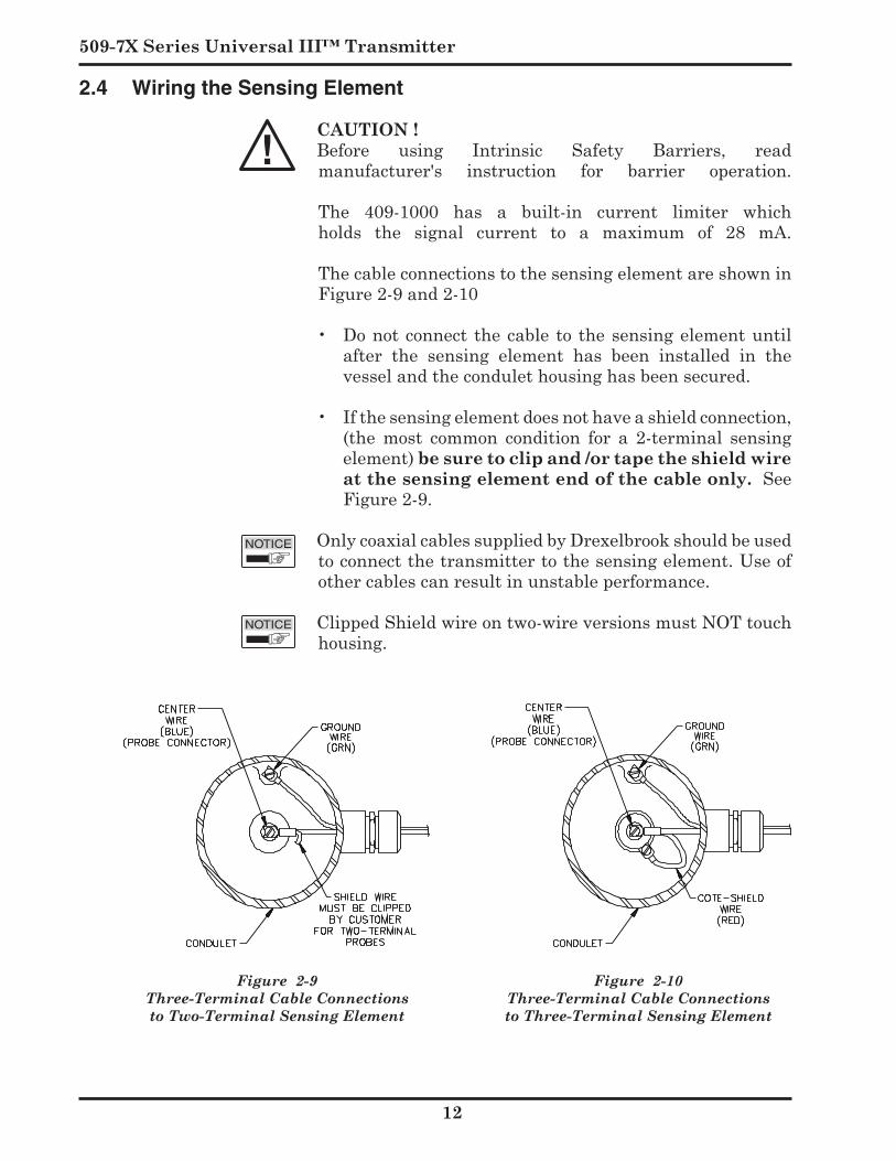
manufacturer's instruction for barrier operation.The 409-1000 has a built-in current limiter whichholds the signal current to a maximum of 28 mA.ThecableconnectionstothesensingelementareshowninFigure2-9and2-10
• Donotconnect thecableto thesensingelementuntilafter the sensing element has been installed in thevesselandthecondulethousinghasbeensecured.
• Ifthesensingelementdoesnothaveashieldconnection,
(the most common condition for a 2-terminal sensingelement) be sure to clip and /or tape the shield wire at the sensing element end of the cable only. SeeFigure2-9.
OnlycoaxialcablessuppliedbyDrexelbrookshouldbeusedtoconnectthetransmittertothesensingelement.Useofothercablescanresultinunstableperformance.
ClippedShieldwireontwo-wireversionsmustNOTtouchhousing.
Figure 2-9Three-Terminal Cable Connections to Two-Terminal Sensing Element
Figure 2-10Three-Terminal Cable Connections to Three-Terminal Sensing Element
Installation
2.5 Spark (Static Electricity) Protection
Spark Protection for Integral Sensing Elements
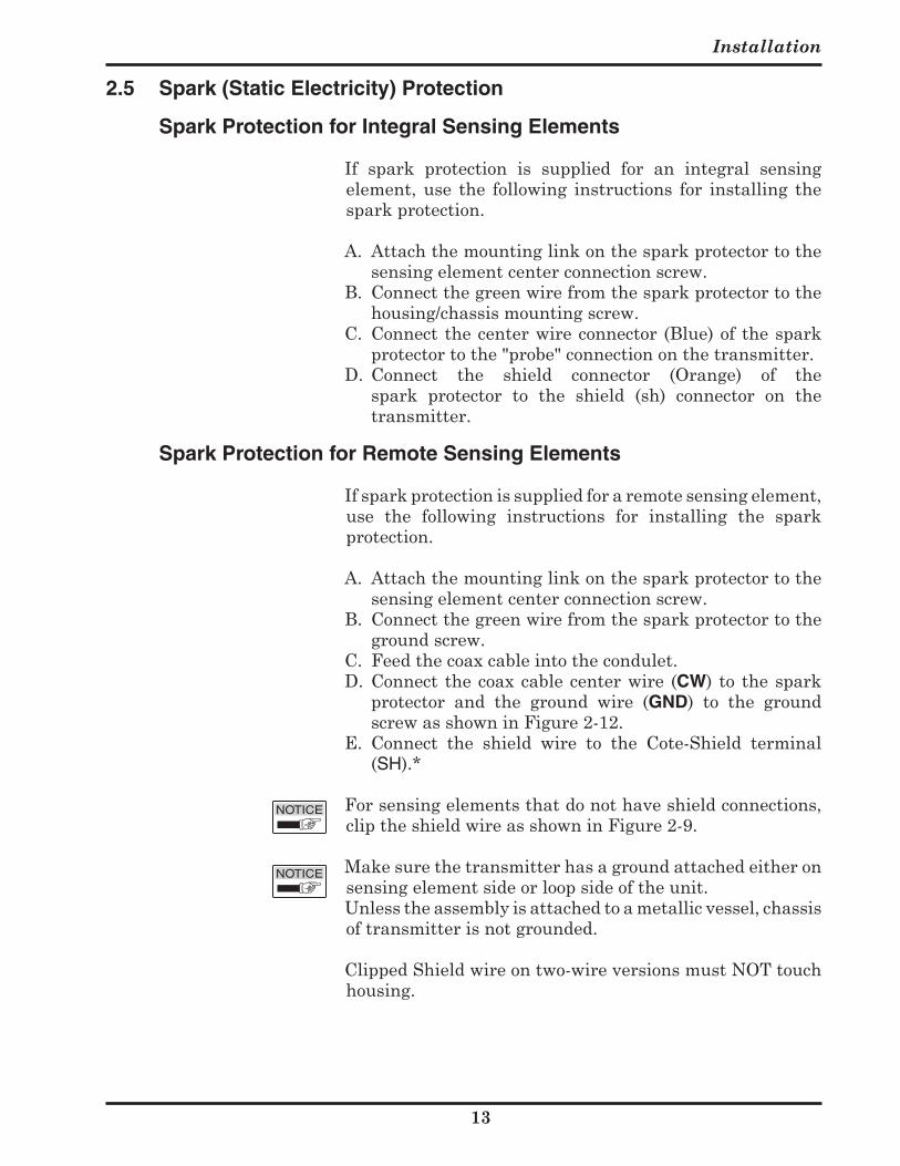
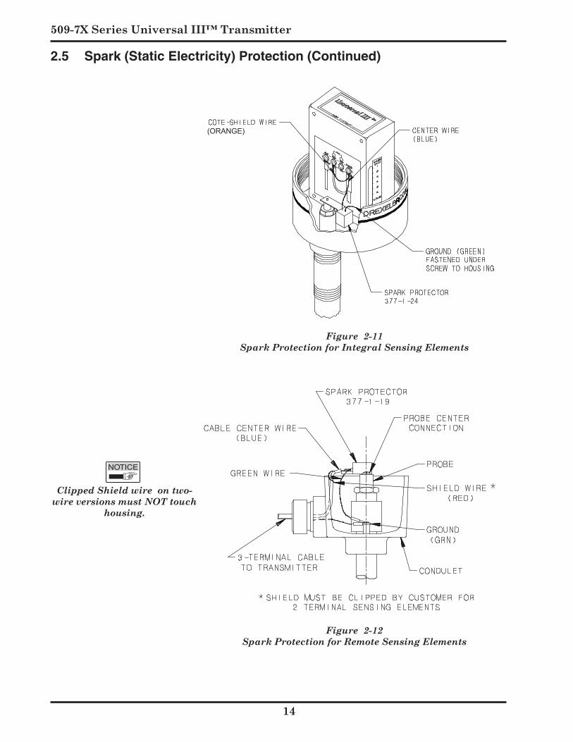
If spark protection is supplied for an integral sensingelement,use the following instructions for installing thesparkprotection.
A. Attachthemountinglinkonthesparkprotectortothesensingelementcenterconnectionscrew.
B. Connectthegreenwirefromthesparkprotectortothehousing/chassismountingscrew.
C. Connectthecenterwireconnector (Blue)ofthesparkprotectortothe"probe"connectiononthetransmitter.
D. Connect the shield connector (Orange) of thespark protector to the shield (sh) connector on thetransmitter.
Spark Protection for Remote Sensing Elements
Ifsparkprotectionissuppliedforaremotesensingelement,use the following instructions for installing the sparkprotection.
A. Attachthemountinglinkonthesparkprotectortothesensingelementcenterconnectionscrew.
B. Connectthegreenwirefromthesparkprotectortothegroundscrew.
C. Feedthecoaxcableintothecondulet.D. Connect thecoaxcablecenterwire (CW) to thespark
protector and the ground wire (GND) to the groundscrewasshowninFigure2-12.
E. Connect the shield wire to the Cote-Shield terminal(SH).*
Forsensingelementsthatdonothaveshieldconnections,cliptheshieldwireasshowninFigure2-9.
Makesurethetransmitterhasagroundattachedeitheronsensingelementsideorloopsideoftheunit.
Unlesstheassemblyisattachedtoametallicvessel,chassisoftransmitterisnotgrounded.
ClippedShieldwireontwo-wireversionsmustNOTtouchhousing.
509-7X Series Universal III™ Transmitter
2.5 Spark (Static Electricity) Protection (Continued)
Figure 2-11Spark Protection for Integral Sensing Elements
(ORANGE)
Figure 2-12Spark Protection for Remote Sensing Elements
Clipped Shield wire on two-wire versions must NOT touch
housing.
Installation
5
2.6 Surge Voltage (Lightning) Protection
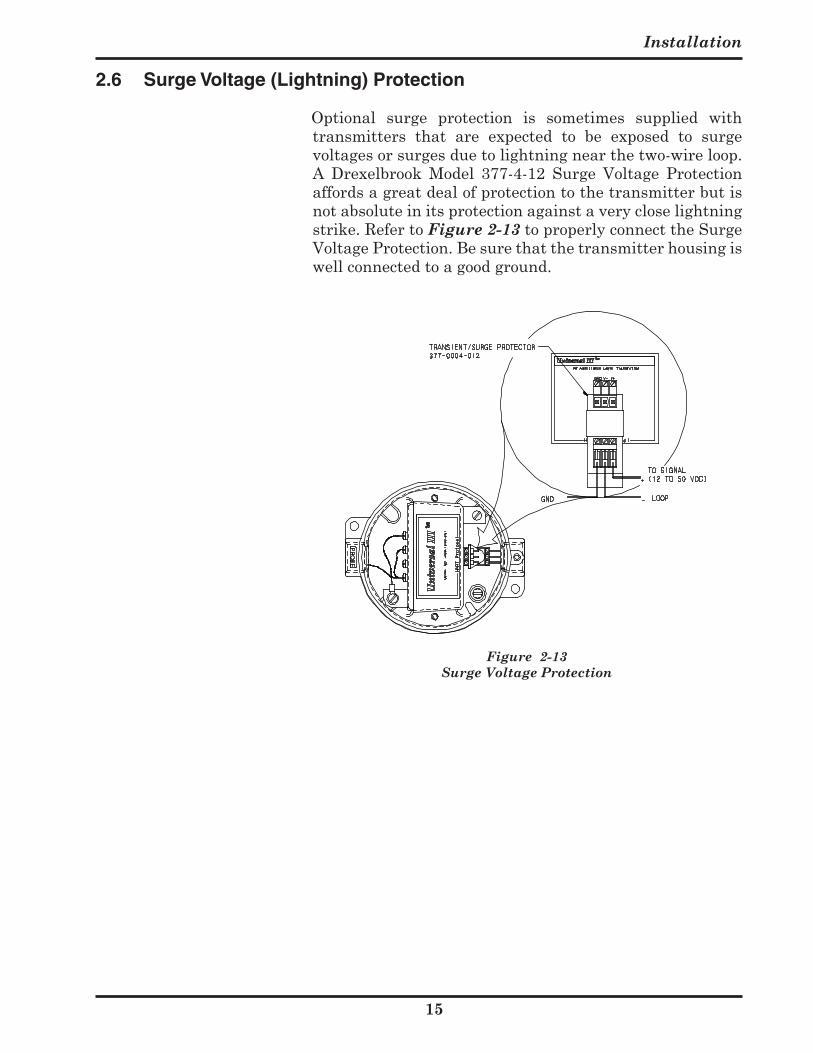
Optional surge protection is sometimes supplied withtransmitters that are expected to be exposed to surgevoltagesorsurgesduetolightningnearthetwo-wireloop.A Drexelbrook Model 377-4-12 Surge Voltage Protectionaffordsagreatdealofprotectiontothetransmitterbutisnotabsoluteinitsprotectionagainstaverycloselightningstrike.RefertoFigure 2-13 toproperlyconnecttheSurgeVoltageProtection.Besurethatthetransmitterhousingiswellconnectedtoagoodground.
Figure 2-13Surge Voltage Protection
509-7X Series Universal III™ Transmitter
2.7 RFI (Radio Frequency Interference) Filters
WheninstallingtheUniversalIIItransmitter,followtheserecommendationstoavoidproblemswithRadio
FrequencyInterference(RFI).
• Choosealocationtomounttheelectronicunitatleast6feet(2M)fromawalkwaywherepersonnelusingwalkietalkiesmaypass.
• If the vessel is non-metallic, select, if possible, ashielded(concentric)sensor.Ifunsureaboutsuitability,contacttheDrexelbrookApplicationsdepartmentforarecommendation.
• For remotely-mounted electronic units connect thesensortotheelectronicunitbyplacingthecoaxialcableingroundedmetalconduit.Integrallymountedelectronicunitsensorconnectionsarealreadyshielded.
• Use Twisted Shielded Pair wiring for all loop wiringconnections.Loopconnectionwiringshouldalsobe ingroundedmetallicconduit.
• Where possible, use of cast aluminum housingswithout windowed openings for the electronic unitis recommended. If local close-coupled indicators areused, install a loop filter between the indicator and the electronicunit.
Groundtheelectronicunitandhousingwithaminimum
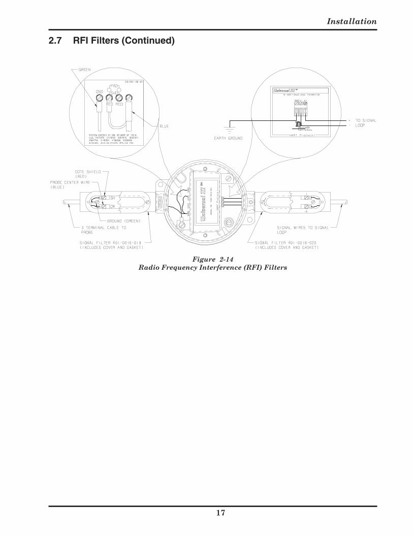
of 14 gauge wire to a good earth ground. Make surethat conduits entering and leaving the housing havea good electrical ground connection to the housingIf the recommendations listed are followed, it is usuallynot necessary to add RFI filtering to protect against signalstrengthsof10Volts/Meterorless.Thisdegreeofprotection is usually sufficient to protect against walkie talkies that are used 3 feet (1M) or more from a typicalelectronic unit. If greater protection is required, or filters have already been provided, install RFI filters as shown in Figure 2-14.
CE Mark Certification:
3-TerminalCoaxialCable-Systemswithremotemountedelectronics require the use of a Probe RFI filter (only) if thesensingelementisconnectedwith3-terminalcoaxialcable, installed in accordance with figure 2-14, to maintain CE Mark certification.
Installation
7
2.7 RFI Filters (Continued)
Figure 2-14Radio Frequency Interference (RFI) Filters
509-7X Series Universal III™ Transmitter
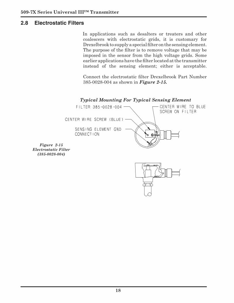
Figure 2-15Electrostatic Filter
(385-0028-004)
Typical Mounting For Typical Sensing Element
2.8 Electrostatic Filters
In applications such as desalters or treaters and othercoalescers with electrostatic grids, it is customary forDrexelbrook to supply a special filter on the sensing element. The purpose of the filter is to remove voltage that may be imposed inthesensor fromthehighvoltagegrids.Someearlier applications have the filter located at the transmitter instead of the sensing element; either is acceptable.Connect the electrostatic filter Drexelbrook Part Number 385-0028-004asshowninFigure 2-15.
Installation
9
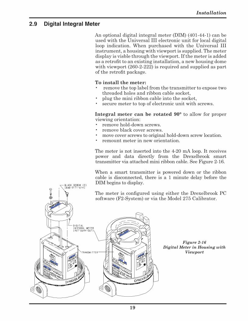
Figure 2-16 Digital Meter in Housing with
Viewport
2.9 Digital Integral Meter
Anoptionaldigitalintegralmeter(DIM)(401-44-1)canbeusedwiththeUniversalIIIelectronicunitforlocaldigitalloop indication. When purchased with the Universal IIIinstrument,ahousingwithviewportissupplied.Themeterdisplayisvisblethroughtheviewport.Ifthemeterisaddedas a retrofit to an existing installation, a new housing dome withviewport(260-2-222)isrequiredandsuppliedaspartof the retrofit package.
To install the meter:• removethetoplabelfromthetransmittertoexposetwo
threadedholesandribboncablesocket,• plugtheminiribboncableintothesocket,• securemetertotopofelectronicunitwithscrews.
Integral meter can be rotated 90° toallowforproperviewing orientation:• removehold-downscrews.• removeblackcoverscrews.• movecoverscrewstooriginalhold-downscrewlocation.• remountmeterinneworientation.
Themeterisnotinsertedintothe4-20mAloop.Itreceivespower and data directly from the Drexelbrook smarttransmitterviaattachedminiribboncable.SeeFigure2-16.
When a smart transmitter is powered down or the ribboncable isdisconnected, there isa1minutedelaybefore theDIMbeginstodisplay.
The meter is configured using either the Drexelbrook PC software(F2-System)orviatheModel275Calibrator.

Section 3
Configuration & Calibration
Section 3: Configuration & Calibration with Drexelbrook PC Software
ThissectioninstructstheuserhowtousetheDrexelbrook401-700-20/40 Series PC calibrator software to configure and calibratetheUniversalIII(RFAdmittance)Transmitter.
3.1 General Description
The 401-700-20/40 software package allows the use ofany Windows® 9X/NT/2000/XP-based personal, laptop,or notebook computer to calibrate the HART Protocoltransmitter.
ThePCsoftwarecanbeusedinplaceoftheRosemount268 or 275 handheld calibrators used for multi-ProcessVariable(PV)transmitters.
3.2 Model Number
0 - 0 7 0 0 - 0 X / X 2X= 1 PC Software Package includes: RS232ModemAssembly401-0700-004 (Figure 3.1). 2X=2 PC Software Package includes: Contentsin401-0700-021,HART®6.0(DOS version) ona
3½"FloppyDisk,andHARTWin™version2.1orgreateronaCD-ROM.
4X=1 PC Software Package includes: USBModemAssembly401-0700-007(Figure 3.1a). 4X=2 PC Software Package includes: Contents in 401-0700-41, Utilities and Drivers on a
CD- ROM, and HARTWin™ version 2.3 or greater on aCD-ROM.
0 - 0 7 0 0 - 0 0 HART®6.0(DOS version) onaCD-ROM. 0 - 0 7 0 0 - 0 HARTWin™version2.XonaCD-ROM.3.3 System Requirements
PC Requirements Windows®95,98,ME,2000,XP. TheUSBmodemisnotcompatiblewithWindows®95,98
FirstEdition,orNT.Itisrecommendedthatthesoftwarebeinstalledonaharddrivewith20megabytesormoreofspaceavailable.
Input to Modem RS232 or USB Port, from one of the COM serial ports
(COM1,COM2,etc.).ThePCprovidesoperatingpowerforthemodembutnotforthetransmitter.
Output (to Transmitter being Calibrated) 4-20mAinHART®Protocol.
509-7X Series Universal III™ Transmitter
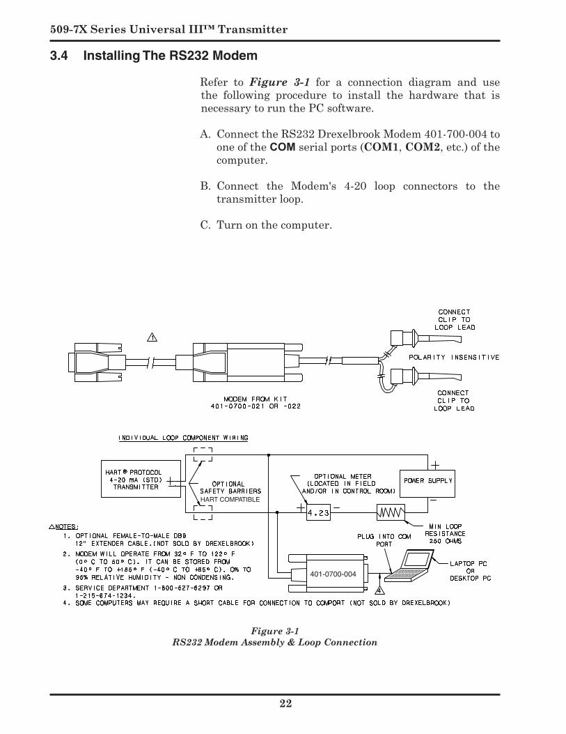
Figure 3-1 RS232 Modem Assembly & Loop Connection
HART COMPATIBLE
401-0700-004
3.4 Installing The RS232 Modem
Refer to Figure 3-1 for a connection diagram and usethe following procedure to install the hardware that isnecessarytorunthePCsoftware.
A. ConnecttheRS232DrexelbrookModem401-700-004tooneoftheCOMserialports(COM,COM,etc.)ofthecomputer.
B. Connect the Modem's 4-20 loop connectors to thetransmitterloop.
C.Turnonthecomputer.
Configuration & Calibration
HART COMPATIBLE
Notes:
1. Modem will operate from 32º F to 122º F (0º C to 50º C). It can be stored from -40º F to +185º F (-40º C to +85º C). 0% to 95% relative humidity - non condensing.
2. Servic Department 1-800-527-6297 or 1-215-674-1234
USB
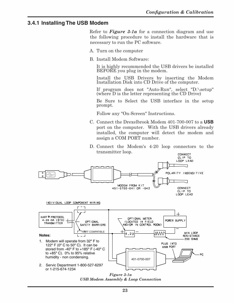
Figure 3-1a USB Modem Assembly & Loop Connection
401-0700-007
3.4.1 Installing The USB Modem
Refer to Figure 3-1a for a connection diagram and usethe following procedure to install the hardware that isnecessarytorunthePCsoftware.
A. TurnonthecomputerB. Install Modem Software: ItishighlyrecommendedtheUSBdriversbeinstalled
BEFOREyoupluginthemodem. Install the USB Drivers by inserting the Modem
InstallationDiskintoCDDriveofthecomputer. If program does not "Auto-Run", select "D:\setup"
(whereDistheletterrepresentingtheCDDrive) Be Sure to Select the USB interface in the setup
prompt.
Followany"On-Screen"Instructions.
C. ConnecttheDrexelbrookModem401-700-007toaUSBporton thecomputer. With theUSBdriversalreadyinstalled, the computer will detect the modem andassignaCOMPORTnumber.
D. Connect the Modem's 4-20 loop connectors to thetransmitterloop.

509-7X Series Universal III™ Transmitter
Figure 3-2Selecting COM ports during
software installation
3.5 Install the Windows Version HARTWin Software on Hard Drive
A. Placethe401-700-031CDintotheCDdrive
B. If program does not "Auto-Run", select "D:\setup" (whereDistheletterrepresentingtheCDDrive).
C. Follow "On-Screen" instructions in Setup to createprogram file.
D. Once loaded, double click "HartWin" icon and theprogramshouldrununderitsownwindow.
E. Selectcommunicationport[Com , Com , etc.]andthenclick“OK.”SeeFigure 3-2
F. If you are not sure which communication portyou are using (such as when first using a USB modem), select “Search Ports,” then OK. Thesoftware automatically will seek out the correct one.IneithercasethesoftwarebeginstocommunicatewiththeHARTprotocoltransmitterandreturnswithaview(below) containing “name plate data,” Tag ID and alldefault or existing configuration information. This is the same as if you clicked on the Read Transmitterfunctionbutton.
G. The next view, shown in Figure 3-3, appearsautomatically,displayingcurrenttransmitterdatabasefor calibration set-up for your selected Tag ID. TheScratchPadwillautomaticallyshowthelastmessage(lastuser,lastcalibration,etc.)upto32characters.Ifthis is a new transmitter, the Tag ID is user-defined. Serialnumber,transmittersoftwareversion,range,etc.is automatically entered from the “name plate data”embedded in the transmitter:
3.6 Description of Function Keys
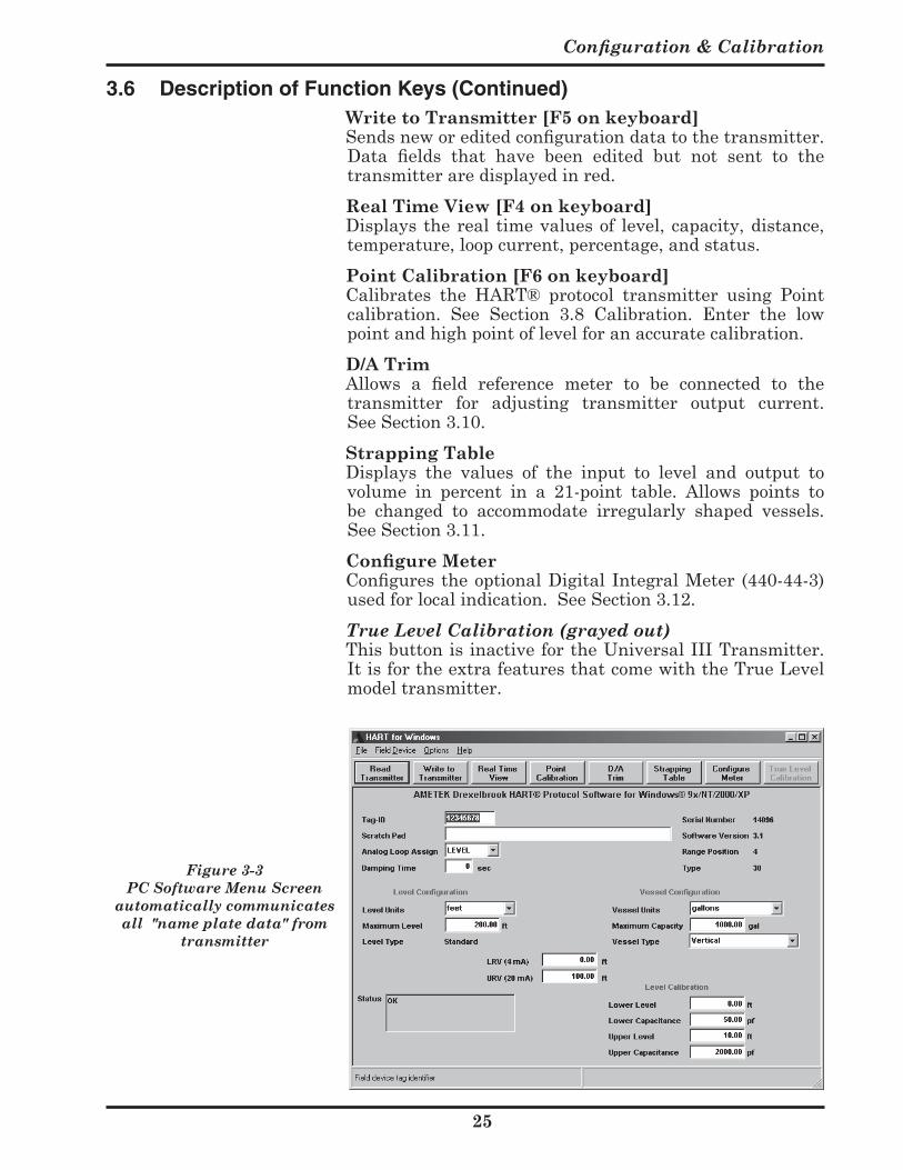
Figure 3-3 showsaPCcalibrationsoftwaremenuscreen.The following paragraphs describe the function buttons.The data fields are described in Section 3.7-Configuration.
Read Transmitter [F on keyboard] Readsallpertinentdatafromthetransmitteranddisplays
itonthescreen.TheReadfunctionalsoupdatestherealtimewindow.Keepinmindthatittakesseveralsecondstoloadtheinformationfromthetransmitter.Whentheloadis complete, the screen shows the database parameters,except any user-defined strapping table information. This command is also used when connecting to anothertransmitter.
Configuration & Calibration
5
3.6 Description of Function Keys (Continued)
Figure 3-3 PC Software Menu Screen
automatically communicates all "name plate data" from
transmitter
Write to Transmitter [F5 on keyboard] Sends new or edited configuration data to the transmitter.
Data fields that have been edited but not sent to the transmitteraredisplayedinred.
Real Time View [F on keyboard] Displaystherealtimevaluesof level,capacity,distance,
temperature,loopcurrent,percentage,andstatus. Point Calibration [F on keyboard] Calibrates the HART® protocol transmitter using Point
calibration. See Section 3.8 Calibration. Enter the lowpointandhighpointoflevelforanaccuratecalibration.
D/A Trim Allows a field reference meter to be connected to the
transmitter for adjusting transmitter output current.SeeSection3.10.
Strapping Table Displays the values of the input to level and output to
volume in percent in a 21-point table. Allows points tobe changed to accommodate irregularly shaped vessels.SeeSection3.11.
Configure Meter Configures the optional Digital Integral Meter (440-44-3)
usedforlocalindication.SeeSection3.12. True Level Calibration (grayed out) ThisbuttonisinactivefortheUniversalIIITransmitter.
ItisfortheextrafeaturesthatcomewiththeTrueLevelmodeltransmitter.
509-7X Series Universal III™ Transmitter
Figure 3-4 Configure Transmitter from
Menu screen
Figure 3-5 Level Configuration from
Menu screen
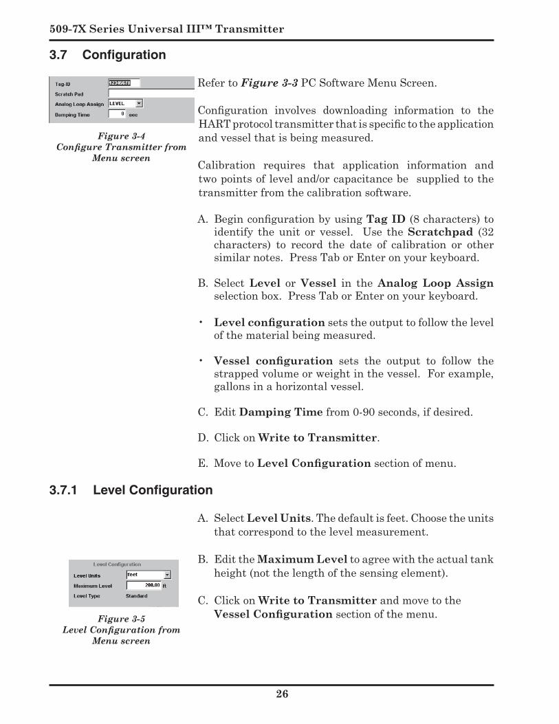
3.7 Configuration
RefertoFigure 3-3PCSoftwareMenuScreen.
Configuration involves downloading information to the HART protocol transmitter that is specific to the application andvesselthatisbeingmeasured.
Calibration requires that application information andtwopointsofleveland/orcapacitancebesuppliedtothetransmitterfromthecalibrationsoftware.
A. Begin configuration by using Tag ID(8characters)toidentify the unit or vessel. Use the Scratchpad (32characters) to record the date of calibration or othersimilarnotes.PressTaborEnteronyourkeyboard.
B. Select Level or Vessel in the Analog Loop Assign selectionbox.PressTaborEnteronyourkeyboard.
• Level configurationsetstheoutputtofollowthelevelofthematerialbeingmeasured.
• Vessel configuration sets the output to follow thestrappedvolumeorweightinthevessel.Forexample,gallons in a horizontal vessel.
C. EditDamping Timefrom0-90seconds,ifdesired.
D. ClickonWrite to Transmitter.
E. MovetoLevel Configurationsectionofmenu.
3.7.1 Level Configuration
A. Select Level Units.Thedefaultisfeet.Choosetheunitsthatcorrespondtothelevelmeasurement.
B. EdittheMaximum Leveltoagreewiththeactualtankheight(notthelengthofthesensingelement).
C. ClickonWrite to Transmitterandmovetothe Vessel Configurationsectionofthemenu.
Configuration & Calibration
7
Figure 3-6 Vessel Configuration from
Menu screen
Figure 3-7 LRV & URV Configuration
from Menu screen
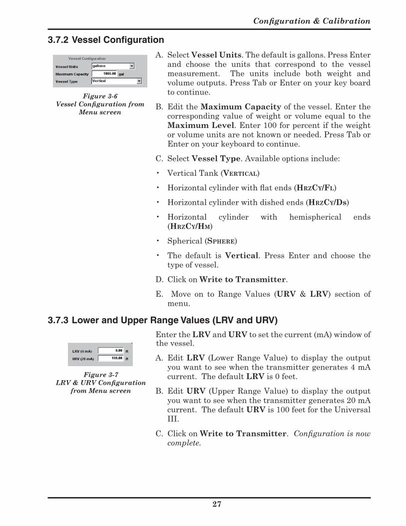
3.7.2 Vessel Configuration
A. SelectVessel Units.Thedefaultisgallons.PressEnterand choose the units that correspond to the vesselmeasurement. The units include both weight andvolumeoutputs.PressTaborEnteronyourkeyboardtocontinue.
B. EdittheMaximum Capacityofthevessel.Enterthecorrespondingvalueofweight orvolumeequal to theMaximum Level.Enter100forpercentiftheweightorvolumeunitsarenotknownorneeded.PressTaborEnteronyourkeyboardtocontinue.
C. SelectVessel Type. Available options include:
• VerticalTank(Vertical)
• Horizontal cylinder with flat ends (Hrzcy/Fl)
• Horizontal cylinder with dished ends (HrzCy/Ds)
• Horizontal cylinder with hemispherical ends (Hrzcy/Hm)
• Spherical(SpHere)
• The default is Vertical. Press Enter and choose thetypeofvessel.
D. ClickonWrite to Transmitter.
E. Move on to Range Values (URV & LRV) section ofmenu.
3.7.3 Lower and Upper Range Values (LRV and URV)
EntertheLRV andURVtosetthecurrent(mA)windowofthevessel.
A. EditLRV (LowerRangeValue) todisplay theoutputyouwanttoseewhenthetransmittergenerates4mAcurrent.ThedefaultLRVis0feet.
B. EditURV (UpperRangeValue)todisplaytheoutputyouwanttoseewhenthetransmittergenerates20mAcurrent.ThedefaultURVis100feetfortheUniversalIII.
C. ClickonWrite to Transmitter.Configuration is now complete.

509-7X Series Universal III™ Transmitter
May use both Point & Level Calibrations
Figure 3-9 Range Span Jumpers
3.8 Calibration
There are two methods for calibrating the transmitterusing the PC software:
Point Calibration: (menu button selection): Usesthetwoknownlevelpointsinthevesselforcalibration.
Thefurtherapartthetwopointsareforthecalibrationthebettertheaccuracyof theoverallmeasurement. AlwaysinitiatethepointcalibrationprocessbyselectingthePoint CalibrationbuttononthePCmenuscreenandfollowingthepromptsinthepop-upwindow.
Level Calibration: SeeFigure3-3(lowerright) Uses capacitance values obtained from the AMETEK
DrexelbrookServicedepartment(orapreviouscalibrationor identical application) for the zero and span calibration data.Call1-800-527-6297.PleaseprovideyourDEpurchaseorder number, transmitter serial number, vessel andapplicationdatatotheServiceEngineer.LevelcalibrationisdoneusingtheLevel Calibration data fields on the PC menuscreen.
It is permissible or sometimes even recommended thatbothmethodsbeused in order to establisha calibrationstandard. For example, if the vessel was already filled before the calibration was attempted and it is difficult or impossibletolowertheleveltoestablishthesecondpoint,it would be best to use a calculated zero capacitance for the lowpointandactual level for thehighpoint.While thiswouldn’tbeasaccurateastwoknownlevelpoints,itwillbereasonablyaccurateuntilanactuallowpointcalibrationcanbeestablished. TheServicedepartmentwillhelp incalculatinghighorlowcapacitancevalues.
Because calibration involves determining two knownpoints of capacitance, a span (or range) jumperprovidesanadjustment for the change in capacitance required toproducefullscalecurrent.
• TheRange Span Jumperislocatedonthesideofthetransmitterchassis.See Fig. 3-9.
• EachRange SpanpositionontheUniversalIIIadvancesthe range in inches or feet to approximately five times theprevioussetting.
See Table 3-1
Configuration & Calibration
9
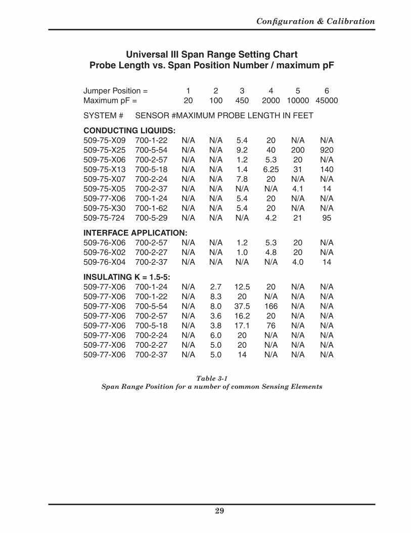
Table 3-1 Span Range Position for a number of common Sensing Elements
Jumper Position = 1 2 3 4 5 6Maximum pF = 20 100 450 2000 10000 45000
SYSTEM # SENSOR # MAXIMUM PROBE LENGTH IN FEET
CONDUCTING LIQUIDS:509-75-X09 700-1-22 N/A N/A 5.4 20 N/A N/A509-75-X25 700-5-54 N/A N/A 9.2 40 200 920509-75-X06 700-2-57 N/A N/A 1.2 5.3 20 N/A509-75-X13 700-5-18 N/A N/A 1.4 6.25 31 140509-75-X07 700-2-24 N/A N/A 7.8 20 N/A N/A509-75-X05 700-2-37 N/A N/A N/A N/A 4.1 14509-77-X06 700-1-24 N/A N/A 5.4 20 N/A N/A509-75-X30 700-1-62 N/A N/A 5.4 20 N/A N/A509-75-724 700-5-29 N/A N/A N/A 4.2 21 95
INTERFACE APPLICATION:509-76-X06 700-2-57 N/A N/A 1.2 5.3 20 N/A509-76-X02 700-2-27 N/A N/A 1.0 4.8 20 N/A509-76-X04 700-2-37 N/A N/A N/A N/A 4.0 14
INSULATING K = 1.5-5:509-77-X06 700-1-24 N/A 2.7 12.5 20 N/A N/A509-77-X06 700-1-22 N/A 8.3 20 N/A N/A N/A509-77-X06 700-5-54 N/A 8.0 37.5 166 N/A N/A509-77-X06 700-2-57 N/A 3.6 16.2 20 N/A N/A509-77-X06 700-5-18 N/A 3.8 17.1 76 N/A N/A509-77-X06 700-2-24 N/A 6.0 20 N/A N/A N/A509-77-X06 700-2-27 N/A 5.0 20 N/A N/A N/A509-77-X06 700-2-37 N/A 5.0 14 N/A N/A N/A
Universal III Span Range Setting ChartProbe Length vs. Span Position Number / maximum pF
509-7X Series Universal III™ Transmitter
0
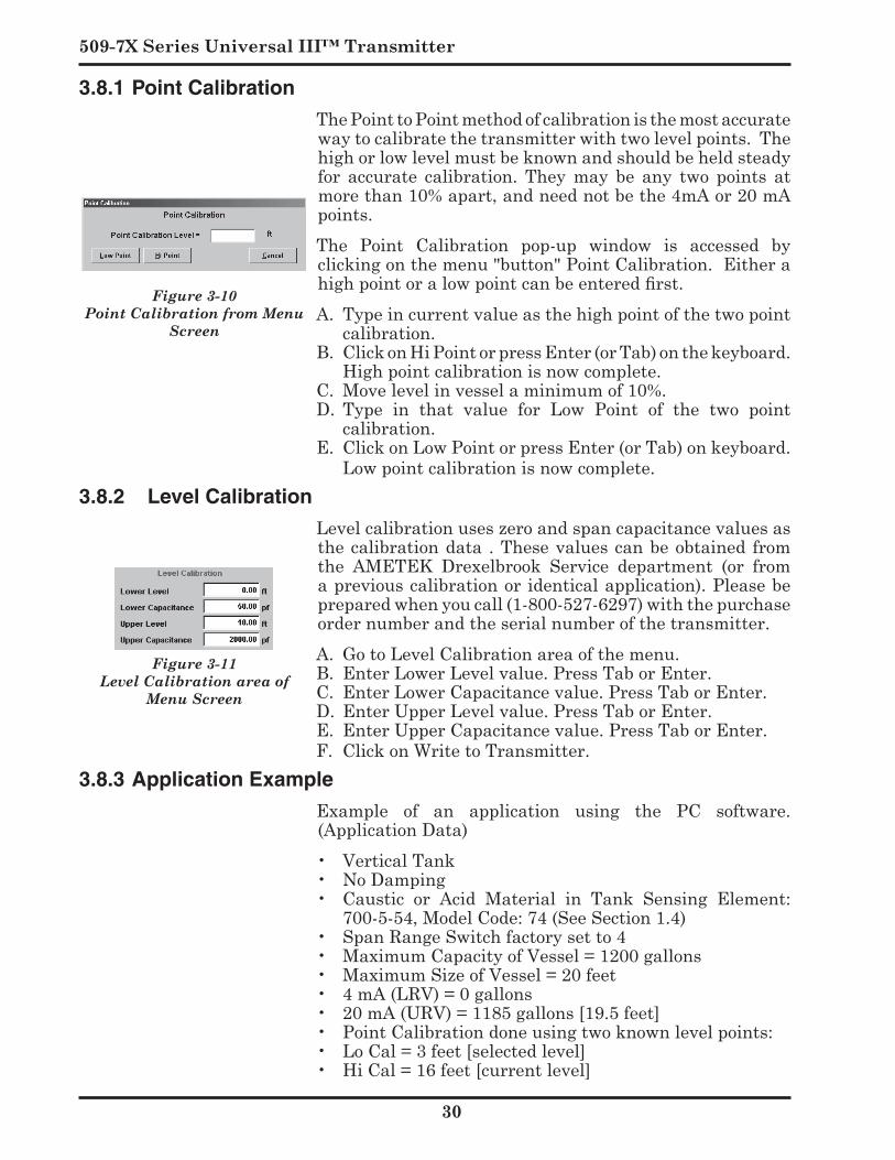
3.8.1 Point Calibration
ThePointtoPointmethodofcalibrationisthemostaccuratewaytocalibratethetransmitterwithtwolevelpoints.Thehighorlowlevelmustbeknownandshouldbeheldsteadyfor accurate calibration. They may be any two points atmorethan10%apart,andneednotbethe4mAor20mApoints.
The Point Calibration pop-up window is accessed byclickingonthemenu"button"PointCalibration.Eitherahigh point or a low point can be entered first.A. Typeincurrentvalueasthehighpointofthetwopoint
calibration.B. ClickonHiPointorpressEnter(orTab)onthekeyboard.
Highpointcalibrationisnowcomplete.C. Movelevelinvesselaminimumof10%.D. Type in that value for Low Point of the two point
calibration.E. ClickonLowPointorpressEnter(orTab)onkeyboard.
Lowpointcalibrationisnowcomplete.3.8.2 Level Calibration
Level calibration uses zero and span capacitance values as thecalibrationdata .Thesevaluescanbeobtained fromthe AMETEK Drexelbrook Service department (or fromapreviouscalibrationoridenticalapplication).Pleasebepreparedwhenyoucall(1-800-527-6297)withthepurchaseordernumberandtheserialnumberofthetransmitter.A. GotoLevelCalibrationareaofthemenu.B. EnterLowerLevelvalue.PressTaborEnter.C. EnterLowerCapacitancevalue.PressTaborEnter.D. EnterUpperLevelvalue.PressTaborEnter.E. EnterUpperCapacitancevalue.PressTaborEnter.F. ClickonWritetoTransmitter.
3.8.3 Application Example
Example of an application using the PC software.(ApplicationData)• VerticalTank• NoDamping• Caustic or Acid Material in Tank Sensing Element:
700-5-54, Model Code: 74 (See Section 1.4)• SpanRangeSwitchfactorysetto4• MaximumCapacityofVessel=1200gallons• Maximum Size of Vessel = 20 feet• 4mA(LRV)=0gallons• 20mA(URV)=1185gallons[19.5feet]• Point Calibration done using two known level points:• LoCal=3feet[selectedlevel]• HiCal=16feet[currentlevel]
Figure 3-11 Level Calibration area of
Menu Screen
Figure 3-10 Point Calibration from Menu
Screen
Configuration & Calibration
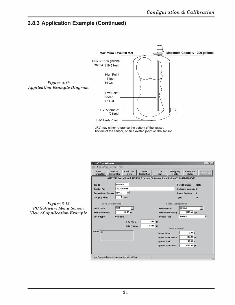
Figure 3-12 Application Example Diagram
LRV 4 mA Point
LRV Alternate*
Low Point3 feetLo Cal
High Point16 feetHi Cal
URV = 1185 gallons 20 mA
Maximum Level 20 feet Maximum Capacity 1200 gallons
*LRV may either reference the bottom of the vessel, bottom of the sensor, or an elevated point on the sensor.
[19.5 feet]
[0 feet]
Figure 3-13 PC Software Menu Screen
View of Application Example
3.8.3 Application Example (Continued)
509-7X Series Universal III™ Transmitter
3.9 PC Status Messages
Status Message:SPAN TOO SMALL Difference between URV and LRV is less than 10% of
range. Example: For 0 to 10 foot calibration points: LRV=3.0 feet
andURV=3.8 feet.Whencalibrationpointsare too closetogether,overallaccuracyofcalibrationisadverselyaffected.Action:Thecalibrationpointsshouldbefartherapart.
Calibration Status Message: RAISE SPAN JUMPER Based on LRV, URV, and capacitance calibration data,
theestimated100%capacitanceexceedsselectedrangebygreaterthan10%.
Example: AunitinRange4(2000pF)projectsmaximumcapacitanceequalto2500pF.Errormessageisdisplayed.Action:RaiseRangejumper(Section3.8,Table3-1)toposition5forthisexample.
Calibration Status Message: LOWER SPAN JUMPER
BasedonLRV,URV,andcapacitancecalibrationdata,theestimated100%capacitancevalueislessthan10%ofthemaximumpFfortherangebelowtheselectedrange.
Example: A unit in Range Span 4 (2000 pF)projects maximum capacitance equal to 400 pF.Action: LowerRangejumper(Section3.8,Table3-1)toposition3(Max.pFof450pF)forthisexample.
Real-time Status Message: UNDERRANGE Presentcapacitance/milliamperevalueislessthan-5%of
range. Examples: Center wire connection is broken.
Sensing element is not operating. An elevatedZero is used and actual level is below 4mApoint. Vessel has lost its RF ground reference.Action: Checkconnectionsandground.Recalibrateifthislevelisinoperationalrangeofprocess.
Real-time Status Message: OVERRANGE Presentcapacitance/milliampvalueover105%ofsystem
span. Examples: Actual level exceeds span point on sensing
element.Cutinsensingelementinsulationorshortedcoax.Action: Checksensingelementandcoax.Re-calibrateifthislevelisinoperationalrangeofprocess.
Figure 3-13a PC Software Menu Screen
View of Main Menu
Configuration & Calibration
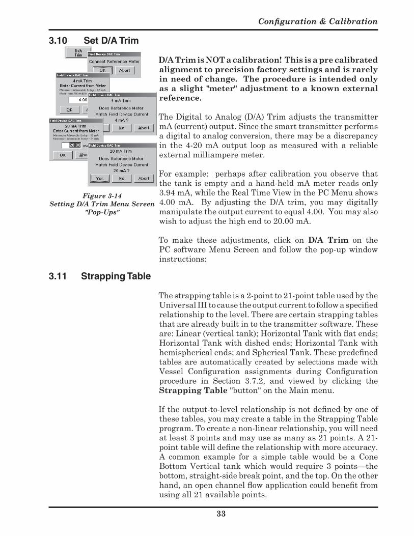
Figure 3-14 Setting D/A Trim Menu Screen
"Pop-Ups"
3.10 Set D/A Trim
D/A Trim is NOT a calibration! This is a pre calibrated alignment to precision factory settings and is rarely in need of change. The procedure is intended only as a slight "meter" adjustment to a known external reference.
TheDigitaltoAnalog(D/A)TrimadjuststhetransmittermA(current)output.Sincethesmarttransmitterperformsadigitaltoanalogconversion,theremaybeadiscrepancyin the 4-20 mA output loop as measured with a reliableexternalmilliamperemeter.
For example: perhaps after calibration you observe that thetankisemptyandahand-heldmAmeterreadsonly3.94mA,whiletheRealTimeViewinthePCMenushows4.00 mA. By adjusting the D/A trim, you may digitallymanipulatetheoutputcurrenttoequal4.00.Youmayalsowishtoadjustthehighendto20.00mA.
To make these adjustments, click on D/A Trim on thePCsoftwareMenuScreenandfollowthepop-upwindowinstructions:
3.11 Strapping Table
Thestrappingtableisa2-pointto21-pointtableusedbytheUniversal III to cause the output current to follow a specified relationshiptothelevel.Therearecertainstrappingtablesthatarealreadybuiltintothetransmittersoftware.Theseare: Linear (vertical tank); Horizontal Tank with flat ends; Horizontal Tank with dished ends; Horizontal Tank with hemispherical ends; and Spherical Tank. These predefined tablesareautomaticallycreatedbyselectionsmadewithVessel Configuration assignments during Configuration procedure in Section 3.7.2, and viewed by clicking theStrapping Table"button"ontheMainmenu.
If the output-to-level relationship is not defined by one of thesetables,youmaycreateatableintheStrappingTableprogram.Tocreateanon-linearrelationship,youwillneedatleast3pointsandmayuseasmanyas21points.A21-point table will define the relationship with more accuracy. A common example for a simple table would be a ConeBottomVertical tankwhichwould require3points—thebottom,straight-sidebreakpoint,andthetop.Ontheotherhand, an open channel flow application could benefit from usingall21availablepoints.
509-7X Series Universal III™ Transmitter
3.11 Strapping Table (Continued)
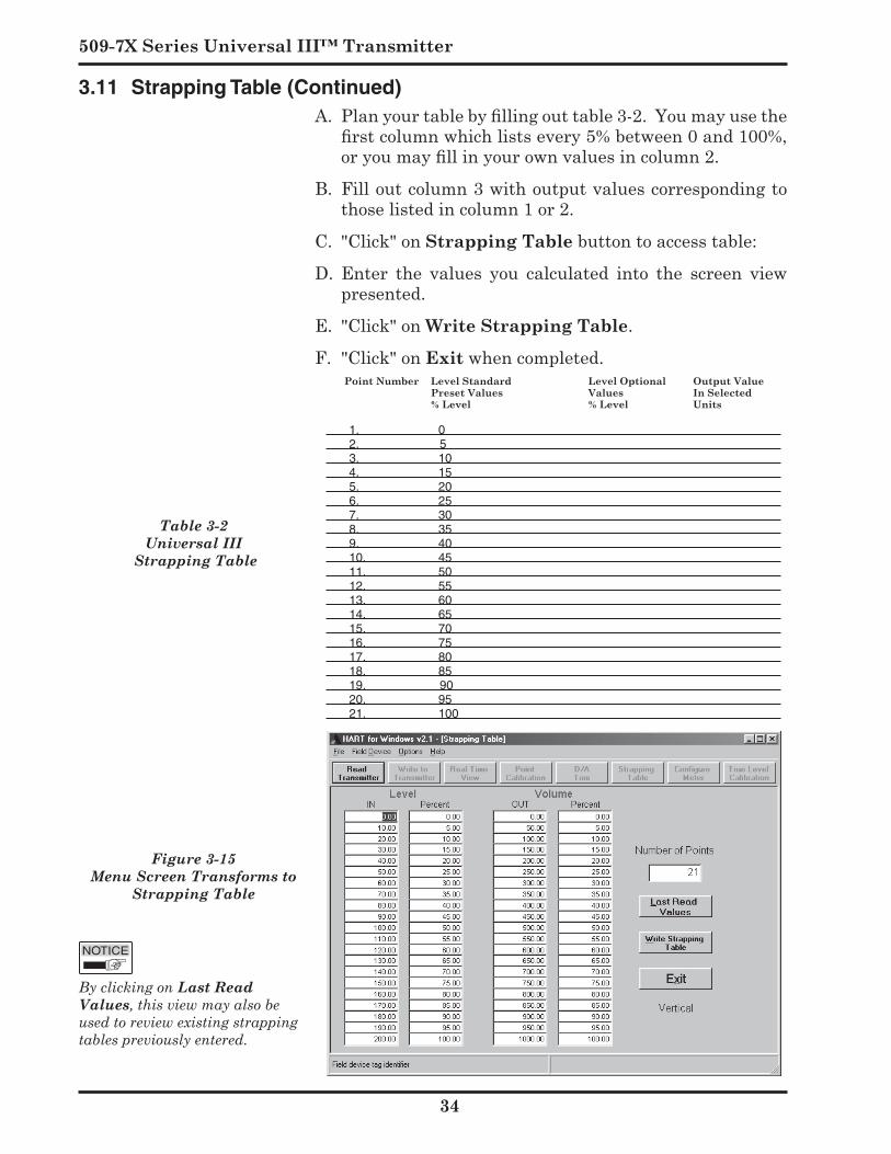
Figure 3-15 Menu Screen Transforms to
Strapping Table
Table 3-2 Universal III
Strapping Table
Point Number Level Standard Level Optional Output Value Preset Values Values In Selected % Level % Level Units
1. 02. 53. 104. 155. 206. 257. 308. 359. 4010. 4511. 5012. 5513. 6014. 6515. 7016. 7517. 8018. 8519. 9020. 9521. 100
By clicking on Last Read Values, this view may also be used to review existing strapping tables previously entered.
A. Plan your table by filling out table 3-2. You may use the first column which lists every 5% between 0 and 100%, or you may fill in your own values in column 2.
B. Filloutcolumn3withoutputvaluescorrespondingtothoselistedincolumn1or2.
C. "Click"onStrapping Table button to access table:
D. Enter the values you calculated into the screen viewpresented.
E. "Click"onWrite Strapping Table.
F."Click"onExitwhencompleted.
Configuration & Calibration
5
3.12 Digital Integral Meter Configuration
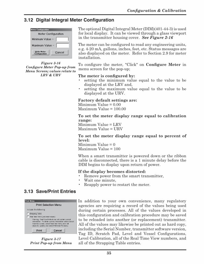
TheoptionalDigitalIntegralMeter(DIM)(401-44-3)isusedforlocaldisplay.Itcanbeviewedthroughaglassviewportinthetransmitterhousingcover.See Figure 2-16
The meter can be configured to read any engineering units, e.g.4-20mA,gallons,inches,feet,etc.Statusmessagesarealsodisplayedonthemeter.RefertoSection2.9formeterinstallation.
To configure the meter, "Click" on Configure Meter inmenuscreenforthepop-up;
The meter is configured by: • setting the minimum value equal to the value to be
displayedattheLRVand,• setting the maximum value equal to the value to be
displayedattheURV. Factory default settings are: MinimumValue=0.00 MaximumValue=100.00 To set the meter display range equal to calibration
range: MinimumValue=LRV MaximumValue=URV To set the meter display range equal to percent of
level: MinimumValue=0 MaximumValue=100 Whenasmarttransmitterispowereddownortheribbon
cableisdisconnected,thereisa1minutedelaybeforetheDIMbeginstodisplayuponreturnofpower.
If the display becomes distorted:• Removepowerfromthesmarttransmitter,• Waitoneminute,• Reapplypowertorestartthemeter.
3.13 Save/Print Entries
In addition to your own convenience, many regulatoryagenciesare requiringa recordof thevaluesbeingusedduring certain processes. All of the values developed inthis configuration and calibration procedure may be saved tobereloadedintoanother(orreplacement)transmitter.Allofthevaluesmaylikewisebeprintedoutashardcopy,includingtheSerialNumber,transmittersoftwareversion,Tag ID, Scratch Pad, Level and Vessel Configurations, LevelCalibration,alloftheRealTimeViewnumbers,andalloftheStrappingTableentries.
Figure 3-16 Configure Meter Pop-up from Menu Screen; values relate to
LRV & URV
Figure 3-17Print Pop-up from Menu
509-7X Series Universal III™ Transmitter
Pop-upscreenscomefromselectionsintheFILEpulldownatthetopleftofthePCmenuScreen.
Copies are saved in both .slt file and .txt files.
The .slt file will download into a transmitter through the OPEN command. The text file may be printed out, or reformatted.
PRINTcommandprovidesapre-formattedhardcopy.
3.14 Validation
Moreandmoreindustriesarerequiringformalvalidationoftheirprocessesfortheircustomersaswellasforvariousgovernment regulatory agencies. The Universal IIITransmitterhasthiscapabilitybuiltin.
3.14.1 Validation Design Concept
Smart RF Continuous Level systems derive their inputinformation from a sensing element that providesa capacitance value to the RF Transmitter. The RFTransmitteroutputsignalisderivedfromthiscapacitancevalue, based on the capacitance span of the transmitterduringinitialcalibration.
If the RF Transmitter's minimum and maximumcapacitancevaluesareknown,andremainunchanged,theeffects of a specific capacitance value within this range can beaccuratelypredicted.Ifaknowncapacitance(whichcanbeNIST-traceable)withinthisrangeproducesrepeatableresults and the minimum and maximum values remainunchanged the RF Level system can be assumed to beoperatingcorrectly.
With a known capacitance input, the output signalwouldnotbe repeatable if the calibration information isaltered,oriftheRFtransmitterwasnotoperatingwithinspecifications. Repeatable calibration information can be maintained through the use of the Save/Print capabilitybuiltintotheUniversalIIITransmitter.
3.13 Save/Print Entries (Continued)
Configuration & Calibration
7
3.14.2 Validation Procedures
A. Drexelbrook Laptop software must be used. Connectthe laptop to the smart level transmitter signal looptobevalidatedandstartthesoftwareaccordingtotheinstructionsprovidedatthebeginningofthisSection.
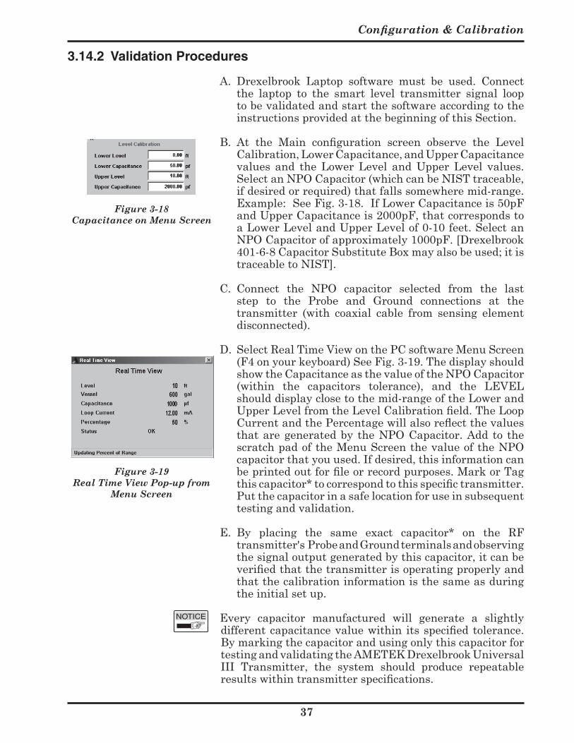
B. At the Main configuration screen observe the Level Calibration,LowerCapacitance,andUpperCapacitancevalues and the Lower Level and Upper Level values.SelectanNPOCapacitor(whichcanbeNISTtraceable,ifdesiredorrequired)thatfallssomewheremid-range.Example: See Fig. 3-18. If Lower Capacitance is 50pF andUpperCapacitanceis2000pF,thatcorrespondstoaLowerLevelandUpperLevelof0-10feet.SelectanNPOCapacitorofapproximately1000pF.[Drexelbrook401-6-8CapacitorSubstituteBoxmayalsobeused;itistraceabletoNIST].
C. Connect the NPO capacitor selected from the laststep to the Probe and Ground connections at thetransmitter (with coaxial cable from sensing elementdisconnected).
D. SelectRealTimeViewonthePCsoftwareMenuScreen(F4onyourkeyboard)SeeFig.3-19.ThedisplayshouldshowtheCapacitanceasthevalueoftheNPOCapacitor(within the capacitors tolerance), and the LEVELshoulddisplayclosetothemid-rangeoftheLowerandUpper Level from the Level Calibration field. The Loop Current and the Percentage will also reflect the values thataregeneratedbytheNPOCapacitor.Addto thescratchpadoftheMenuScreenthevalueoftheNPOcapacitorthatyouused.Ifdesired,thisinformationcanbe printed out for file or record purposes. Mark or Tag this capacitor* to correspond to this specific transmitter. Putthecapacitorinasafelocationforuseinsubsequenttestingandvalidation.
E. By placing the same exact capacitor* on the RFtransmitter'sProbeandGroundterminalsandobservingthesignaloutputgeneratedbythiscapacitor,itcanbeverified that the transmitter is operating properly and thatthecalibrationinformationisthesameasduringtheinitialsetup.
Every capacitor manufactured will generate a slightlydifferent capacitance value within its specified tolerance. BymarkingthecapacitorandusingonlythiscapacitorfortestingandvalidatingtheAMETEKDrexelbrookUniversalIII Transmitter, the system should produce repeatableresults within transmitter specifications.
Figure 3-18 Capacitance on Menu Screen
Figure 3-19 Real Time View Pop-up from
Menu Screen

509-7X Series Universal III™ Transmitter
Figure 3-20 Typical Printout of Transmitter Data
AMETEK Drexelbrook205 Keith Valley RoadHorsham, PA 19044
Telephone: 215-674-1234FAX: 215-674-2731
Service: 800-527-6297
Tag-ID: LT 101 Serial Number: 1172Scratch PAD: 1000 pf NPO validation capacitor Software Version: 3.1Analog Loop Assign: LEVEL Range Position: 4Damping Time: 0 sec. Type: 30
Level Configuration Vessel Configuration Level CalibrationLevel Units: feet Vessel Units: gallons Lower Level: 0 ftMaximum Level: 10.00 ft Maximum Capacity: 1200.00 gal Upper Level: 10 ftLevel Type: Standard Vessel Type: Vertical Lower Capacitance: 50 pf
Upper Capacitance: 2000 pfLRV (4mA): 0.00 ftURV (20 mA): 10.00ft
Real Time View
Level: 10 ftVessel: 600 galCapacitance: 1000 pFLoop Current: 12.00 mAPercentage: 50 %Status: OK
Strapping Table
Vessel Type: VerticalNumber of Points: 21
Level VolumeIn Percent Out Percent
0.00 0.00 o.oo 0.001.00 5.00 60.00 5.002.00 10.00 120.00 10.003.00 15.00 180.00 15.004.00 20.00 240.00 20.005.00 25.00 300.00 25.006.00 30.00 360.00 30.007.00 35.00 420.00 35.008.00 40.00 480.00 40.009.00 45.00 540.00 45.0010.00 50.00 600.00 50.0011.00 55.00 660.00 55.0012.00 60.00 720.00 60.0013.00 65.00 780.00 65.0014.00 70.00 840.00 70.0015.00 75.00 900.00 75.0016.00 80.00 960.00 80.0017.00 85.00 1020.00 85.0018.00 90.00 1080.00 90.0019.00 95.00 1140.00 95.0020.00 100.00 1200.00 100.00
3.14.3 Validation Results
See Fig. 3-20. Iftheinformationthatisshown(orprinted)matchesthe
initial readings within system specifications, then it can be verified that the calibration and configuration is as originally set. It can also be verified that the transmitter’s responsefallswithinacceptabletolerances.Thesystemhaspassedvalidationtests.UsingtheSave/Printfeaturebuiltintothetransmitterallowstheabilitytocomplywiththerecord-keeping needed for many processes by regulatoryagencies.
Configuration & Calibration
9
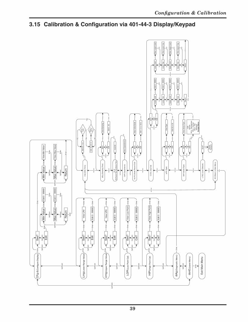
3.15 Calibration & Configuration via 401-44-3 Display/Keypad
Edi
t E
dit
Min
Val
ue
Up/
Dow
n
CF
g.d
(Con
figur
e D
ispl
ay)
See
?
Min
Val
ue
Max
Val
ue
Ent
er0
- 99
900
Edi
t 0 -
999
00E
nter
Up/
Dow
n
Ret
urn
Up/
Dow
n
Ent
er
Up/
Dow
n
Ent
er
Ent
er
Up/
Dow
nU
p/D
own
Max
Val
ue
Ent
erV
iew
Min
Val
ue
Vie
w M
ax V
alue
Ent
er
Up/
Dow
n
Ret
urn
Up/
Dow
n
Up/
Dow
n
Ent
er
Ent
er
Ent
er
Ent
erE
nter
Ent
er
I.AdJ
(DA
C T
rims)
Edi
t 3.5
- 4
.5V
alue
=4.
0?E
nter
No
Edi
t 19.
0-21
.0
Yes
Val
ue =
20.0
?E
nter
Yes
No
dELy
(Dam
ping
Tim
e)S
ee?
Edi
t
Up/
Dow
n
Ent
er
Up/
Dow
n
Vie
w D
ampi
ngE
nter
Edi
t 0 -
90
Ent
er
Ent
er
Ent
er
Up/
Dow
n
Sr.H
r(S
oftw
are
Rev
/Har
dwar
e R
ev)
S.S
.HH
Ent
erE
nter
Up/
Dow
n
CA
P (C
apac
itanc
e)V
iew
Cap
acita
nce
Ent
erE
nter
Sc.
PO
(Sca
le P
erce
nt O
ut)
See
?
Edi
t
Up/
Dow
n
Ent
er
Up/
Dow
n
Vie
w %
Out
Sca
leE
nter
Edi
t 1.0
or
100.
0E
nter
Ent
er
Ent
er
Up/
Dow
n
Up/
Dow
n
Up/
Dow
n
Ent
er
Up/
Dow
n
C.C
AL
(Cap
Cal
)S
ee?
Edi
t
Up/
Dow
nLo
wer
Lev
el
Low
er C
ap
Ent
erE
dit 0
- 9
9900
Edi
t 0 -
999
00E
nter
Up/
Dow
n
Ret
urn
Up/
Dow
n
Ent
er
Up/
Dow
n
Ent
er
Ent
er
Up/
Dow
nLo
wer
Lev
el
Low
er C
ap
Ent
erV
iew
Low
er L
evel
Vie
w L
ower
Cap
Ent
er
Up/
Dow
n
Ret
urn
Up/
Dow
n
Up/
Dow
n
Ent
er
Ent
er
Ent
er
Ent
erE
nter
Ent
er
Upp
er L
evel
Upp
er C
ap
Ent
erE
dit 0
- 9
9900
Edi
t 0 -
999
00E
nter
Up/
Dow
nE
nter
Upp
er L
evel
Upp
er C
ap
Ent
erV
iew
Upp
er L
evel
Vie
w U
pper
Cap
Ent
er
Up/
Dow
nE
nter
Ent
erU
p/D
own
Ent
er
Up/
Dow
n
Up/
Dow
n
Edi
t
tyP
E (T
ype)
See
?
Edi
t
Up/
Dow
n
Ent
er
Up/
Dow
n
Vie
w T
ype
Ent
er
Edi
t 00
or 3
0E
nter
Ent
er
Ent
er
Str
P (V
esse
l Typ
e)S
ee?
Edi
t
Up/
Dow
n
Ent
er
Up/
Dow
n
Vie
w V
esse
l Typ
eE
nter
Sph
ere
HC
yl -
Hem
isph
ere
HC
yl -
Dis
hed
HC
yl -
Fla
tS
tand
ard
Esc
ape
Men
u
Ent
er
Ent
er
Ent
er
Up/
Dow
n
Up/
Dow
n
L.FA
C (
Load
Def
aults
)S
ure?
Ent
erU
p/D
own
Dev
ice
Res
tart
s
Ent
er
rEt (
Ret
urn
to M
ain
Men
u)
Up/
Dow
n
Ent
er
Up/
Dow
n
Ent
er
Up/
Dow
n
Lrng
(Low
er R
ange
Val
ue)
See
?
Edi
t
Ent
er
Up/
Dow
n
Vie
w L
RV
Ent
er
Edi
t 0 -
999
00E
nter
Ent
er
Ent
er
Urn
g (U
pper
Ran
ge V
alue
)S
ee?
Edi
t
Up/
Dow
n
Ent
er
Up/
Dow
n
Vie
w U
RV
Ent
er
Edi
t 0 -
999
00E
nter
Ent
er
Ent
er
Up/
Dow
n
LOP
t (Lo
w P
oint
Cal
)S
ee?
Cal
?
Up/
Dow
n
Ent
er
Up/
Dow
n
Vie
w L
ow P
oint
Ent
er
Edi
t 0 -
999
00E
nter
Ent
er
Ent
er
Up/
Dow
n
HIP
t (H
igh
Poi
nt C
al)
See
?
Cal
?
Up/
Dow
n
Ent
er
Up/
Dow
n
Vie
w H
igh
Poi
ntE
nter
Edi
t 0 -
999
00E
nter
Ent
er
Ent
er
Up/
Dow
n
diA
g (D
iagn
ostic
Men
u)
Up/
Dow
n
donE
(Lea
ve M
enu)
Up/
Dow
n
Exi
t Mai
n M
enu
Ent
er

Section 4
Configuration & Calibration
Section 4: Configuration and Calibration Using the Rosemount™ Model 275 Communicator with a Drexelbrook Device Description
4.1 Drexelbrook Device Description
TheDrexelbrookDeviceDescriptionfortheRosemount275handheldcalibratormakesiteasytocalibrateaUniversalIII.Thedevicedescriptionsoftwareisstoredinthememorymodule(locatedinthebackportion)ofthecalibrator.
Todetermine ifyourModel275HandheldcalibratorhastheDrexelbrookDeviceDescriptionloaded,dothefollowingsteps:
• Turnonthecalibrator.• From the top screen, push 1. Offline.• Push 1. New Configuration• A Table of Contents is shown that lists all the
Manufacturersinalphabeticalorder.• Select the Manufacturer (Drexelbrook) and a list of
supporteddevicesisdisplayed(UniversalIII).• Returntotopscreen,bybackingupfromarrowkeys.
The Memory Module with the device description can bepurchasedasadirectreplacementeitherfromDrexelbrook(401-700-25) or from the local Fisher-Rosemount ServiceCenter.
Section 5 describes configuration of the Universal III transmitter with a Rosemount 275 handheld calibratorwithoutadevicedescription.
4.2 Start-up
After the Universal III transmitter is installed and looppower is applied, per Section 2, do the following:
1. ConnecttheRosemountModel275(ShowninFig.4-1).2. TurnontheCalibratorandlookfortheONLINEscreen
to appear. ONLINE means that the 275 Calibratorhas recognized the Universal III and is ready for Configuration and Calibration.
3. You must start the process by doing the Configuration first-- followed by Calibration. There are also instructions for configuring the Strapping Tables and for doing a D/A Trimtomaketheloopoutputagreewithacalibrationstandardforloopcurrent.
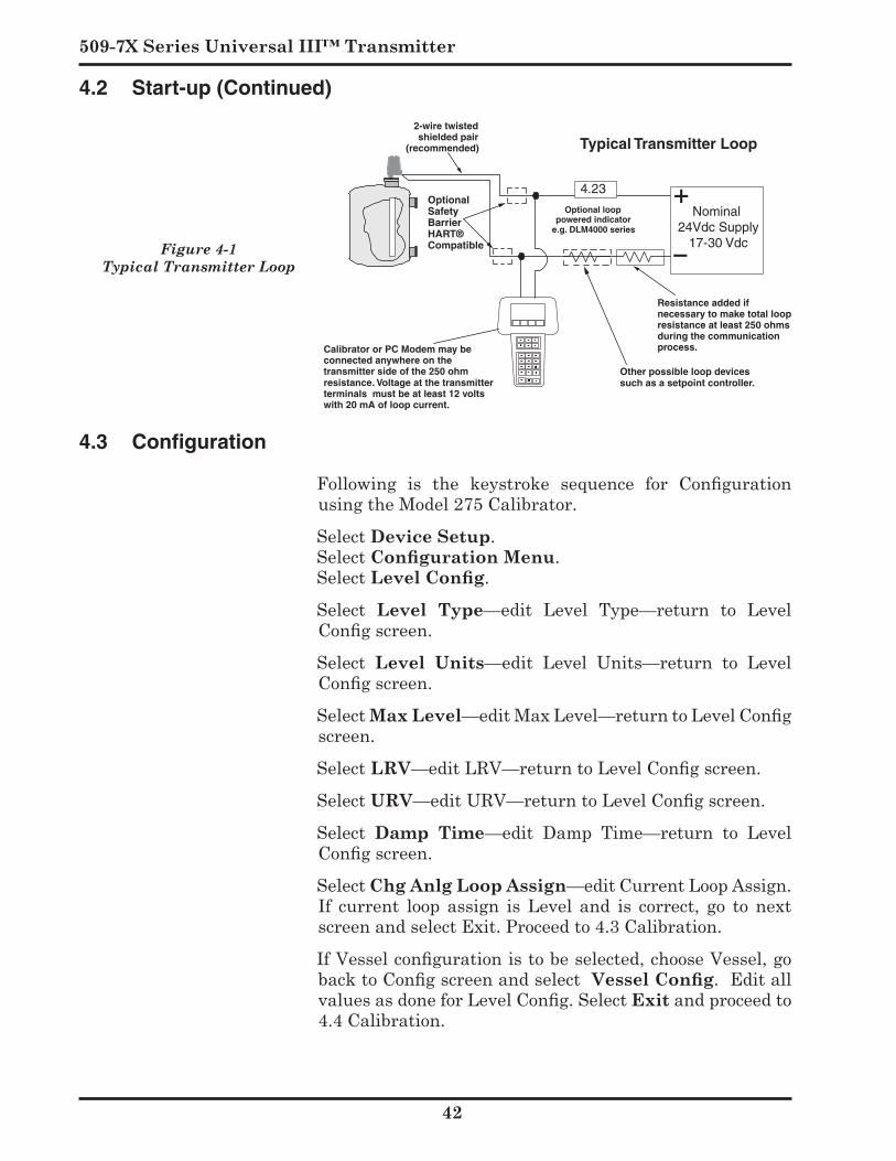
509-7X Series Universal III™ Transmitter
Figure 4-1 Typical Transmitter Loop
Typical Transmitter Loop
Nominal 24Vdc Supply
17-30 Vdc
ABC7 DEF8GHI9
ABC7DEF8
GHI9
ABC7DEF8 GHI9
ABC7DEF8 GHI9
ABC7DEF8
GHI9
ABC7DEF8
GHI9
ABC7DEF8
GHI9
–
+
Resistance added ifnecessary to make total loopresistance at least 250 ohmsduring the communicationprocess.
2-wire twistedshielded pair
(recommended)
4.23
Optional looppowered indicator
e.g. DLM4000 series
Calibrator or PC Modem may be connected anywhere on thetransmitter side of the 250 ohmresistance. Voltage at the transmitterterminals must be at least 12 voltswith 20 mA of loop current.
Other possible loop devicessuch as a setpoint controller.
Optional Safety BarrierHART® Compatible
4.3 Configuration
Following is the keystroke sequence for Configuration usingtheModel275Calibrator.
SelectDevice Setup. SelectConfiguration Menu. SelectLevel Config.
Select Level Type—edit Level Type—return to LevelConfig screen.
Select Level Units—edit Level Units—return to LevelConfig screen.
SelectMax Level—edit Max Level—return to Level Config screen.
Select LRV—edit LRV—return to Level Config screen.
SelectURV—edit URV—return to Level Config screen.
Select Damp Time—edit Damp Time—return to LevelConfig screen.
SelectChg Anlg Loop Assign—editCurrentLoopAssign.If current loop assign is Level and is correct, go to nextscreenandselectExit.Proceedto4.3Calibration.
If Vessel configuration is to be selected, choose Vessel, go back to Config screen and select Vessel Config.Editallvalues as done for Level Config. Select Exitandproceedto4.4Calibration.
4.2 Start-up (Continued)
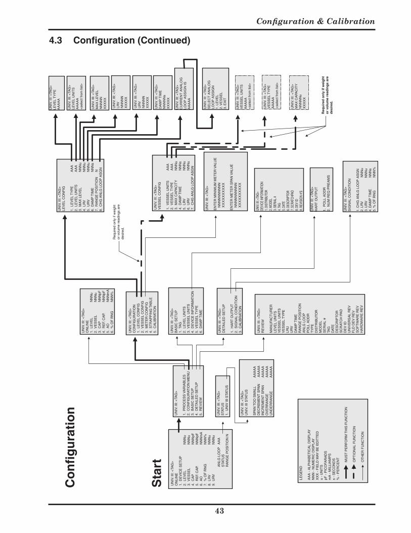
Configuration & Calibration
UN
IV. I
II: <
TAG
>O
NLI
NE
1. D
EV
ICE
SE
TU
P2.
LE
VE
LN
NN
u3.
VE
SS
EL
NN
Nu
4. C
AP
NN
NpF
5. R
EF.
CA
P.N
NN
pF6.
AO
NN
Nm
A7.
% O
F R
NG
NN
N%
8. L
RV
NN
Nu
9. U
RV
NN
Nu
AN
LG L
OO
PA
AA
STA
TU
SR
AN
GE
PO
SIT
ION
N
UN
IV. I
II: <
TAG
>O
NLI
NE
1. L
EV
EL
NN
Nu
2. V
ES
SE
LN
NN
u3.
CA
PN
NN
pF4.
RE
F. C
AP.
NN
NpF
5. A
ON
NN
mA
6. %
OF
RN
GN
NN
%
UN
IV. I
II: <
TAG
>C
ON
FIG
UR
ATIO
N1.
LE
VE
L C
ON
FIG
2. V
ES
SE
L C
ON
FIG
3. M
ET
ER
CO
NF
IG4.
ST
RA
PP
ING
TA
BLE
5. C
ALI
BR
ATIO
N
UN
IV. I
II: <
TAG
>B
AS
IC S
ET
UP
1. T
AG
2. L
EV
EL
UN
ITS
3. V
ES
SE
L U
NIT
S4.
DE
VIC
E IN
FO
RM
ATIO
N5.
VE
SS
EL
TY
PE
6. D
AM
P T
IME
UN
IV. I
II: <
TAG
>LE
VE
L C
ON
FIG
1. L
EV
EL
TY
PE
AA
A2.
LE
VE
L U
NIT
SA
AA
3. M
AX
LE
VE
LN
NN
u4.
LR
VN
NN
u5.
UR
VN
NN
u6.
DA
MP
TIM
EN
NN
s7.
RA
NG
E P
OS
ITIO
NN
8. C
HG
AN
LG L
OO
P A
SG
N
UN
IV. I
II: <
TAG
>V
ES
SE
L C
ON
FIG
1. V
ES
SE
L U
NIT
SA
AA
2. V
ES
SE
L T
YP
EA
AA
3. M
AX
CA
PAC
ITY
NN
Nu
4. D
AM
P T
IME
NN
Ns
5. L
RV
NN
Nu
6. U
RV
NN
Nu
7. C
HG
AN
LG L
OO
P A
SG
N
UN
IV. I
II: <
TAG
>D
ETA
ILE
D S
ET
UP
1. H
AR
T O
UT
PU
T2.
SIG
NA
L C
ON
DIT
ION
3. C
ALI
BR
ATIO
N
UN
IV. I
II: <
TAG
>R
EV
IEW
MA
NU
FAC
TU
RE
RLE
VE
L U
NIT
SV
ES
SE
L U
NIT
SV
ES
SE
L T
YP
ELR
UU
RV
DA
MP
TIM
ER
AN
GE
PO
SIT
ION
AN
LG L
OO
PP
OLL
AD
DR
TY
PE
DIS
TR
IBU
TOR
MO
DE
LS
ER
IAL
#TA
GD
ATE
DE
SC
RIP
TOR
SC
RAT
CH
PA
DD
EV
IDU
NIV
ER
SA
L R
EV
FLD
DE
V R
EV
SO
FT
WA
RE
RE
VH
AR
DW
AR
E R
EV
UN
IV. I
II: <
TAG
>
1. P
RO
CE
SS
VA
RIA
BLE
S2.
CO
NF
IGU
RAT
ION
ME
NU
3. B
AS
IC S
ET
UP
4. D
ETA
ILE
D S
ET
UP
5. R
EV
IEW
UN
IV. I
II: <
TAG
>S
TAT
US
1. U
NIV
III S
TAT
US
UN
IV. I
II: <
TAG
>U
NIV
. III
STA
TU
S
SPA
N T
OO
SM
ALL
A
AA
AA
DE
CR
EM
EN
T S
PAN
AA
AA
AIN
CR
EM
EN
T S
PAN
AA
AA
AO
VE
RR
AN
GE
A
AA
AA
UN
DE
RR
AN
GE
AA
AA
A
LEG
EN
D
AA
A -
ALP
HA
BE
TIC
AL
DIS
PLA
YN
NN
- N
UM
ER
IC D
ISP
LAY
XX
X -
FIE
LD M
AY B
E E
DIT
TE
Du
- U
NIT
SpF
- P
ICO
FAR
AD
Sm
A -
MIL
LIA
MP
Ss
- S
EC
ON
DS
% -
PE
RC
EN
T
MU
ST
PE
RF
OR
M T
HIS
FU
NC
TIO
N
OP
TIO
NA
L F
UN
CT
ION
OT
HE
R F
UN
CT
ION
Req
uire
d on
ly if
wei
ght
or v
olum
e re
adin
gs a
rede
sire
d.
Sta
rt
Co
nfi
gu
rati
on
Req
uir
ed o
nly
if w
eig
ht
or
volu
me
read
ing
s ar
ed
esir
ed.
UN
IV. I
II: <
TAG
>
EN
TE
R M
INIM
UM
ME
TE
R V
ALU
E
NN
NN
NN
NN
NN
X
XX
XX
XX
XX
X
EN
TE
R M
ET
ER
SPA
N V
ALU
E
NN
NN
NN
NN
NN
X
XX
XX
XX
XX
X
UNIV
. III: <
TAG>
DEVI
CE IN
FORM
ATIO
N1.
DIST
RIBU
TOR
2. M
ODEL
3. SE
RIAL
#4.
TAG
5. DA
TE6.
DESC
RIPT
OR7.
SCRA
TCHP
AD8.
DEV
ID9.
REVI
SION
#'S
UN
IV. I
II: <
TAG
>H
AR
T O
UT
PU
T
1. P
OLL
AD
DR
2. N
UM
RE
Q P
RE
AM
S
UN
IV. I
II: <
TAG
>S
IGN
AL
CO
ND
ITIO
N
1. C
HG
AN
LG L
OO
P A
SG
N2.
LR
V
N
NN
u3.
UR
V
N
NN
u4.
DA
MP
TIM
E
N
NN
s5.
% O
F R
NG
NN
N%
UN
IV. I
II: <
TAG
>LE
VE
L T
YP
EA
AA
AA
UN
IV. I
II: <
TAG
>LE
VE
L U
NIT
SA
AA
AA
<se
lect
from
list
>
UN
IV. I
II: <
TAG
>M
AX
LE
VE
LN
NN
NN
XX
XX
X
UN
IV. I
II: <
TAG
>LR
VN
NN
NN
XX
XX
X
UN
IV. I
II: <
TAG
>U
RV
NN
NN
NX
XX
XX
UN
IV. I
II: <
TAG
>D
AM
P T
IME
NN
NN
Ns
XX
XX
X
UN
IV. I
II: <
TAG
>C
UR
RE
NT
AN
ALO
GLO
OP
AS
SIG
N IS
AA
AA
A
UN
IV. I
II: <
TAG
>S
ELE
CT
AN
ALO
GLO
OP
AS
SIG
N1.
LE
VE
L2.
VE
SS
EL
3. E
XIT
UN
IV. I
II: <
TAG
>V
ES
SE
L U
NIT
SA
AA
AA
<se
lect
from
list
>
UN
IV. I
II: <
TAG
>V
ES
SE
L T
YP
EA
AA
AA
<se
lect
from
list
>
UN
IV. I
II: <
TAG
>M
AX
CA
PAC
ITY
NN
NN
Nu
XX
XX
X
4.3 Configuration (Continued)
509-7X Series Universal III™ Transmitter
4.4 Calibration
There are two methods of calibrating the UniversalIII transmitter: Point Calibration or Capacitance Calibration.
Point calibration uses the actual level in your vessel forcalibration.The furtherapart the twopointsare for thecalibration, then the better the accuracy of the overallmeasurement.
Capacitance calibration uses values obtained from theDrexelbrookServicedepartment(orapreviouscalibrationor identical application) for the zero and span calibration data. Call 1-800-527-6297 for assistance. Please providethe purchase order number, transmitter serial numberandapplicationinformationtotheServiceEngineer.
It is permissible or sometimes even recommended thatbothmethodsbeused in order to establisha calibrationstandard. For example, if the vessel was already filled before the calibration was attempted and it is difficult or impossibletolowertheleveltoestablishthesecondpoint,it would be best to use a calculated zero capacitance for the lowpointandactual level for thehighpoint. Whilethis wouldn’t be as accurate as two known level points,it will be reasonably accurate until an actual low pointcanbeestablished. TheServicedepartmentwillhelp incalculatinghighorlowcapacitancevalues.
4.4.1 Point Calibration FollowingisthekeystrokesequenceforPointCalibration
usingtheModel275Calibrator.
SelectDevice Setup. SelectConfiguration Menu. SelectCalibration.
SelectPoint Cal—selecteitherLow Point CalorHigh Point Caldependingonwhetheryouplantoraiseorlowerthe level foryoursecondpoint—editvalue toagreewiththepresentactuallevelandreturntoPointCalscreen.
Exit—Calibrationiscomplete.
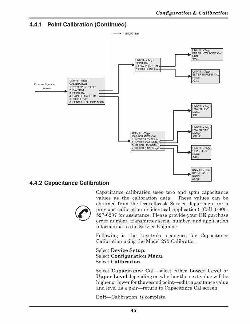
Configuration & Calibration
5
UNIV.III: <Tag>POINT CAL1. LOW POINT CAL2. HIGH POINT CAL
UNIV.III: <Tag>ENTER LOW POINT CALNNNuXXXu
UNIV.III: <Tag>ENTER HI POINT CALNNNuXXXu
UNIV.III: <Tag>CAPACITANCE CAL1. LOWER LEV NNNu2. LOWER CAP NNNpF3. UPPER LEV NNNu4. UPPER CAP NNNpF
UNIV.III: <Tag>CALIBRATION1. STRAPPING TABLE2. D/A TRIM3. POINT CAL4. CAPACITANCE CAL5. TRUE LEVEL6. CHNG ANLG LOOP ASGN
UNIV.III: <Tag>LOWER LEVNNNuXXXu
UNIV.III: <Tag>LOWER CAPNNNpFXXXpF
UNIV.III: <Tag>UPPER LEVNNNuXXXu
UNIV.III: <Tag>UPPER CAPNNNpFXXXpF
From configuration
screen
To D/A Trim
4.4.2 Capacitance Calibration
Capacitance calibration uses zero and span capacitance values as the calibration data. These values can beobtained from the Drexelbrook Service department (or aprevious calibrationor identicalapplication).Call1-800-527-6297forassistance.PleaseprovideyourDEpurchaseordernumber,transmitterserialnumber,andapplicationinformationtotheServiceEngineer.
Following is the keystroke sequence for CapacitanceCalibrationusingtheModel275Calibrator.
SelectDevice Setup. SelectConfiguration Menu. SelectCalibration.
Select Capacitance Cal—select either Lower Level orUpper Leveldependingonwhetherthenextvaluewillbehigherorlowerforthesecondpoint—editcapacitancevalueandlevelasapair—returntoCapacitanceCalscreen.
Exit—Calibrationiscomplete.
4.4.1 Point Calibration (Continued)
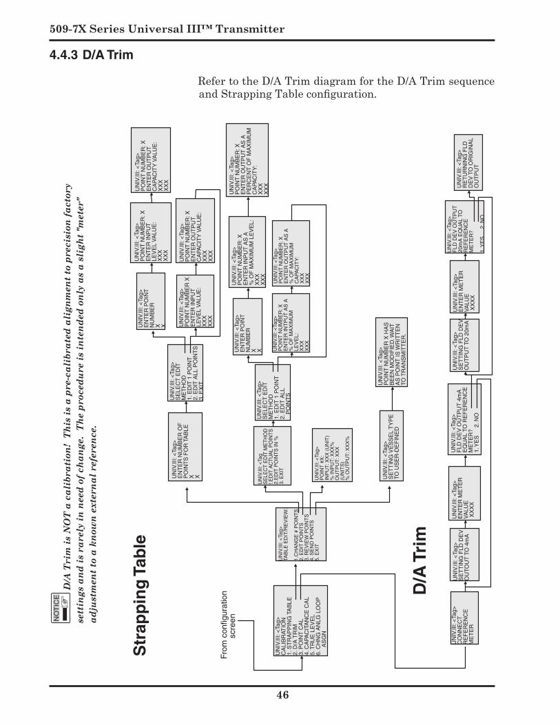
509-7X Series Universal III™ Transmitter
Str
app
ing
Tab
le
From
con
figur
atio
n
scre
en
UN
IV.II
I: <
Tag>
CA
LIB
RAT
ION
1. S
TR
AP
PIN
G T
AB
LE2.
D/A
TR
IM3.
PO
INT
CA
L4.
CA
PAC
ITA
NC
E C
AL
5. T
RU
E L
EV
EL
6. C
HN
G A
NLG
LO
OP
A
SG
N
UN
IV.II
I: <
Tag>
TAB
LE E
DIT
/RE
VIE
W:
1.C
HA
NG
E #
PO
INT
S2.
ED
IT P
OIN
TS
3. R
EV
IEW
PO
INT
S4.
SE
ND
PO
INT
S5.
EX
IT
UN
IV.II
I: <
Tag>
CO
NN
EC
TR
EF
ER
EN
CE
M
ET
ER
UN
IV.II
I: <
Tag>
SE
TT
ING
FLD
DE
V
OU
TOU
T T
O 4
mA
UN
IV.II
I: <
Tag>
EN
TE
R M
ET
ER
V
ALU
E X
XX
X
UN
IV.II
I: <
Tag>
FLD
DE
V O
UT
PU
T 4
mA
E
QU
AL
TO R
EF
ER
EN
CE
M
ET
ER
?1.
YE
S
2. N
O
UN
IV.II
I: <
Tag>
SE
TT
ING
FLD
DE
V
OU
TP
UT
TO
20m
A
UN
IV.II
I: <
Tag>
EN
TE
R M
ET
ER
V
ALU
E X
XX
X
UN
IV.II
I: <
Tag>
FLD
DE
V O
UT
PU
T20
mA
EQ
UA
L TO
R
EF
ER
EN
CE
M
ET
ER
?
1. Y
ES
2
. NO
UN
IV.II
I: <
Tag>
RE
TU
RN
ING
FLD
D
EV
TO
OR
IGIN
AL
OU
TP
UT
UN
IV.II
I: <
Tag>
SE
TT
ING
VE
SS
EL
TY
PE
TO
US
ER
-DE
FIN
ED
UN
IV.II
I: <
Tag>
PO
INT
NU
MB
ER
X H
AS
B
EE
N M
OD
IFIE
D. W
AIT
A
S P
OIN
T IS
WR
ITT
EN
TO
TR
AN
SM
ITT
ER
.
UN
IV.II
I: <
Tag>
PO
INT
NU
MB
ER
: X
EN
TE
R O
UT
PU
T
CA
PAC
ITY
VA
LUE
:X
XX
XX
X
UN
IV.II
I: <
Tag>
PO
INT
NU
MB
ER
: X
EN
TE
R O
UT
PU
T A
S A
P
ER
CE
NT
OF
MA
XIM
UM
C
APA
CIT
Y:
XX
XX
XX
UN
IV.II
I: <
Tag>
PO
INT
NU
MB
ER
: X
EN
TE
R IN
PU
T
LEV
EL
VA
LUE
:X
XX
XX
X
UN
IV.II
I: <
Tag>
PO
INT
NU
MB
ER
: X
EN
TE
R O
UT
PU
T
CA
PAC
ITY
VA
LUE
:X
XX
XX
X
UN
IV.II
I: <
Tag>
PO
INT
NU
MB
ER
: X
EN
TE
R IN
PU
T A
S A
% O
F M
AX
IMU
M L
EV
EL:
XX
XX
XX
UN
IV.II
I: <
Tag>
PO
INT
NU
MB
ER
: X
EN
TE
R O
UT
PU
T A
S A
% O
F M
AX
IMU
M
CA
PAC
ITY
:X
XX
XX
X
UN
IV.II
I: <
Tag>
EN
TE
R P
OIN
TN
UM
BE
RX X U
NIV
.III:
<Ta
g>P
OIN
T N
UM
BE
R X
EN
TE
R IN
PU
T
LEV
EL
VA
LUE
:X
XX
XX
X
UN
IV.II
I: <
Tag>
SE
LEC
T E
DIT
M
ET
HO
D1.
ED
IT 1
PO
INT
2. E
DIT
ALL
PO
INT
S3.
EX
IT
UN
IV.II
I: <
Tag>
EN
TE
R N
UM
BE
R O
F
PO
INT
S F
OR
TA
BLE
X X
UN
IV.II
I: <T
agS
ELE
CT
ED
IT M
ET
HO
D!.E
DIT
AC
TU
AL
PO
INT
S2.
ED
IT P
OIN
TS
IN %
3. E
XIT
UN
IV.II
I: <
Tag>
SE
LEC
T E
DIT
M
ET
HO
D1.
ED
IT 1
PO
INT
2. E
DIT
ALL
P
OIN
TS
UN
IV.II
I: <
Tag>
PO
INT
#X
:IN
PU
T: X
XX
(U
NIT
)%
INP
UT
: XX
X%
OU
TP
UT
: XX
X(U
NIT
S)
% O
UT
PU
T: X
XX
%
UN
IV.II
I: <
Tag>
EN
TE
R P
OIN
T
NU
MB
ER
X X UN
IV.II
I: <
Tag>
PO
INT
NU
MB
ER
: X
EN
TE
R IN
TP
UT
AS
A%
OF
MA
XIM
UM
LE
VE
L:X
XX
XX
X
D/A
Tri
m
D/A
Tri
m is
NO
T a
cal
ibra
tion
! T
his
is a
pre
-cal
ibra
ted
alig
nmen
t to
prec
isio
n fa
ctor
y se
ttin
gs a
nd is
rar
ely
in n
eed
of c
hang
e. T
he p
roce
dure
is in
tend
ed o
nly
as a
sli
ght "
met
er"
adju
stm
ent t
o a
know
n ex
tern
al r
efer
ence
.
Str
app
ing
Tab
le
4.4.3 D/A Trim
RefertotheD/ATrimdiagramfortheD/ATrimsequenceand Strapping Table configuration.
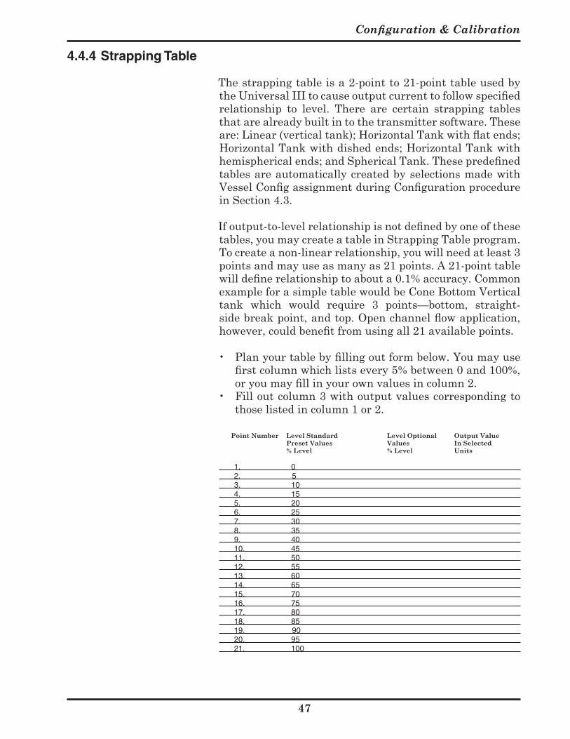
Configuration & Calibration
7
4.4.4 Strapping Table
Thestrappingtableisa2-pointto21-pointtableusedbythe Universal III to cause output current to follow specified relationship to level. There are certain strapping tablesthatarealreadybuiltintothetransmittersoftware.Theseare: Linear (vertical tank); Horizontal Tank with flat ends; Horizontal Tank with dished ends; Horizontal Tank with hemispherical ends; and Spherical Tank. These predefined tablesareautomaticallycreatedbyselectionsmadewithVessel Config assignment during Configuration procedure inSection4.3.
If output-to-level relationship is not defined by one of these
tables,youmaycreateatableinStrappingTableprogram.Tocreateanon-linearrelationship,youwillneedatleast3pointsandmayuseasmanyas21points.A21-pointtablewill define relationship to about a 0.1% accuracy. Common exampleforasimpletablewouldbeConeBottomVerticaltank which would require 3 points—bottom, straight-side break point, and top. Open channel flow application, however, could benefit from using all 21 available points.
• Plan your table by filling out form below. You may use first column which lists every 5% between 0 and 100%, or you may fill in your own values in column 2.
• Filloutcolumn3withoutputvaluescorrespondingtothoselistedincolumn1or2.
Point Number Level Standard Level Optional Output Value Preset Values Values In Selected % Level % Level Units
1. 02. 53. 104. 155. 206. 257. 308. 359. 4010. 4511. 5012. 5513. 6014. 6515. 7016. 7517. 8018. 8519. 9020. 9521. 100

Section 5
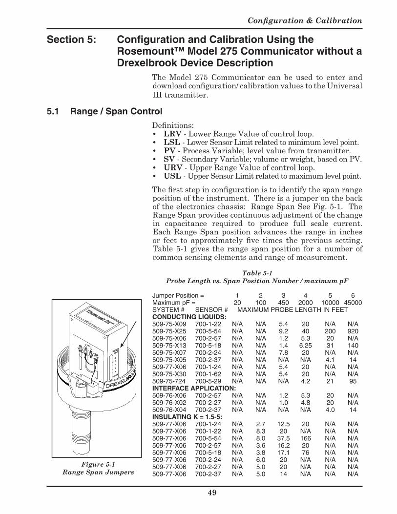
Configuration & Calibration
9
Section 5: Configuration and Calibration Using the Rosemount™ Model 275 Communicator without a Drexelbrook Device Description
The Model 275 Communicator can be used to enter anddownload configuration/ calibration values to the Universal IIItransmitter.
5.1 Range / Span Control
Definitions: • LRV-LowerRangeValueofcontrolloop.• LSL -LowerSensorLimitrelatedtominimumlevelpoint.• PV -ProcessVariable;levelvaluefromtransmitter.• SV -SecondaryVariable;volumeorweight,basedonPV.• URV-UpperRangeValueofcontrolloop.• USL-UpperSensorLimitrelatedtomaximumlevelpoint.
The first step in configuration is to identify the span range positionoftheinstrument.Thereisajumperonthebackof the electronics chassis: Range Span See Fig. 5-1. The RangeSpanprovidescontinuousadjustmentofthechangein capacitance required to produce full scale current.Each Range Span position advances the range in inchesor feet to approximately five times the previous setting. Table 5-1 gives the range span position for a number ofcommonsensingelementsandrangeofmeasurement.
Jumper Position = 1 2 3 4 5 6Maximum pF = 20 100 450 2000 10000 45000SYSTEM # SENSOR # MAXIMUM PROBE LENGTH IN FEETCONDUCTING LIQUIDS:509-75-X09 700-1-22 N/A N/A 5.4 20 N/A N/A509-75-X25 700-5-54 N/A N/A 9.2 40 200 920509-75-X06 700-2-57 N/A N/A 1.2 5.3 20 N/A509-75-X13 700-5-18 N/A N/A 1.4 6.25 31 140509-75-X07 700-2-24 N/A N/A 7.8 20 N/A N/A509-75-X05 700-2-37 N/A N/A N/A N/A 4.1 14509-77-X06 700-1-24 N/A N/A 5.4 20 N/A N/A509-75-X30 700-1-62 N/A N/A 5.4 20 N/A N/A509-75-724 700-5-29 N/A N/A N/A 4.2 21 95INTERFACE APPLICATION:509-76-X06 700-2-57 N/A N/A 1.2 5.3 20 N/A509-76-X02 700-2-27 N/A N/A 1.0 4.8 20 N/A509-76-X04 700-2-37 N/A N/A N/A N/A 4.0 14INSULATING K = 1.5-5:509-77-X06 700-1-24 N/A 2.7 12.5 20 N/A N/A509-77-X06 700-1-22 N/A 8.3 20 N/A N/A N/A509-77-X06 700-5-54 N/A 8.0 37.5 166 N/A N/A509-77-X06 700-2-57 N/A 3.6 16.2 20 N/A N/A509-77-X06 700-5-18 N/A 3.8 17.1 76 N/A N/A509-77-X06 700-2-24 N/A 6.0 20 N/A N/A N/A509-77-X06 700-2-27 N/A 5.0 20 N/A N/A N/A509-77-X06 700-2-37 N/A 5.0 14 N/A N/A N/A
Table 5-1 Probe Length vs. Span Position Number / maximum pF
Figure 5-1 Range Span Jumpers
509-7X Series Universal III™ Transmitter
50
5.2 Rules & Conventions of HART Configuration Software (Model 275)
To become familiar with the operation of the Model 275Communicator,itisbesttoreviewtheOperatingManualthatcomeswiththeunit.Thisparagraphreviewssomeofthe basic characteristics of the Model 275 configuration/calibrationsoftware.Thefollowingpagesshowthedecisiontreemenus.
Arrow Keys: Use the arrow keys to move through thesoftwaremenus.Anarrowatthebeginningofthemenuitemindicatesthenextprogressivestep.
Alphanumeric Keys: Usethealphanumerickeystoenterdata. Data fields are characterized by a blinking cursor.
Function Keys: The function keys, F1 through F4,indicate the specific actions that are available to complete thesoftwarefunction.Theactionwordsthatappearaboveeachkeychangeasyoumovethroughthemenusandselectthesoftwaretask.
Heart Symbol: When a appears in the upper rightcornerofthescreen,communicationisoccurringbetweenthecommunicatorandthetransmitter.
5.3 Tag ID
Tonameor identify the transmitter,use the8-characterTagID.TheTagIDisenteredorchangedinthefollowingmenus.
a) selecttheONLINEMAINmenu b) ⇒1DEVICESETUP ⇒ ⇓ ⇓ c) ⇒3BASICSETUP⇒ d) ⇒1TAG⇒ e) change(usealphanumerickeys)TagID f) F4ENTER g) F2SEND h) F4OK i) F4OK or: a) selecttheONLINEMAINmenu b) ⇒1DEVICESETUP⇒ ⇓ ⇓ c) ⇒3BASICSETUP⇒ ⇓ ⇓ ⇓ d) ⇒4DEVICEINFORMATION⇒ ⇓ ⇓ ⇓ e) ⇒4TAG⇒ f) change(usealphanumerickeys)TagID g) F4ENTER h) F2SEND i) F4OK j) F4OK k) F3HOME
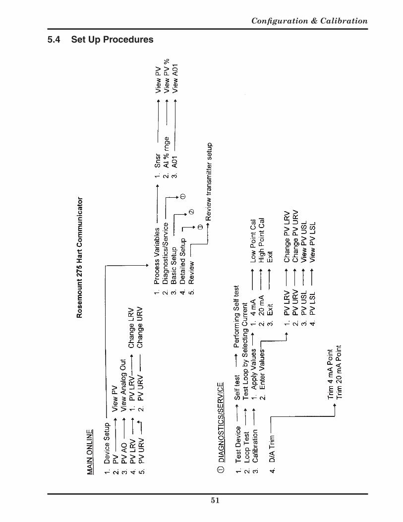
Configuration & Calibration
5
5.4 Set Up Procedures
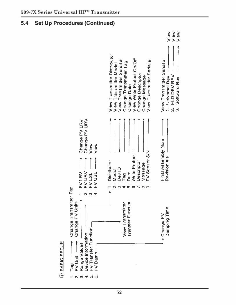
509-7X Series Universal III™ Transmitter
5
5.4 Set Up Procedures (Continued)
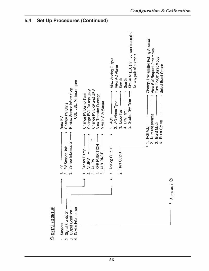
Configuration & Calibration
5
5.4 Set Up Procedures (Continued)
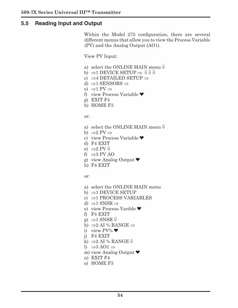
509-7X Series Universal III™ Transmitter
5
5.5 Reading Input and Output
Within the Model 275 configuration, there are several differentmenusthatallowyoutoviewtheProcessVariable(PV)andtheAnalogOutput(AO1).
View PV Input:
a) selecttheONLINEMAINmenu ⇓b) ⇒1DEVICESETUP ⇒ ⇓ ⇓ ⇓c) ⇒4DETAILEDSETUP⇒d) ⇒1SENSORS⇒e) ⇒1PV⇒f) viewProcessVariableg) EXITF4h) HOMEF3
or:
a) selecttheONLINEMAINmenu⇓b) ⇒2PV⇒c) viewProcessVariabled) F4EXITe) ⇒2PV⇓f) ⇒3PVAOg) viewAnalogOutputh) F4EXIT
or:
a) selecttheONLINEMAINmenub) ⇒1DEVICESETUPc) ⇒1PROCESSVARIABLESd) ⇒1SNSR⇒e) viewProcessVariblef) F4EXITg) ⇒1SNSR⇓h) ⇒2AI%RANGE⇒i) viewPV%j) F4EXITk) ⇒2AI%RANGE⇓l) ⇒3AO1⇒m)viewAnalogOutputn) EXITF4o) HOMEF3
Configuration & Calibration
55
5.6 Calibration Using Actual Tank Level
When calibrating using a handheld without a devicedescription,tanklevelmust be moved.Calibrationisatwo-stepprocess. Alowpointcalibrationandhighpointcalibrationare required. Calibrationpointsdonothaveto be an empty tank or a full tank. (example: low point performedat20%andhighpointperformedat80%willwork). Youalsomay performhighpoint calbefore lowpointcal.
From main screen go to: 1 Devicesetup 2 Diag/Service 3 Calibration 4 Entervalues
You now have four choices: 1 PVLRV 2 PVURV 3 PVUSL 4 PVLSL
ChoosePV LRVifyourvesselcurrentlyhasalowlevel. ChoosePV URVifyourvesselcurrentlyhasahighlevel. Edit the displayed value to equal the actual tank level, then:
ENTER SEND OK OK ⇐ 1 Applyvalues OK
You now have two choices: 1 4mA 2 20mA
Choose20mAifperformingahighpointcalibration. Choose4mAifperformingalowpointcalibration. Continue: OK ENTER 3 EXIT OK HOME ObserveonthehomescreenthatyourPV URV or PV LRV
valuehasbeenchangedbythecalibrationprocedure.Youmustmanuallychangethesevaluesback.Re-enteryourdesiredPV URVandPV LRVatthistime.
This completes the first calibration point of the two-step process. For the second point, change the level in yourtankandrepeattheentireaboveprocedure.
509-7X Series Universal III™ Transmitter
5
5.7 Bench Calibration (if needed)
When performing a bench calibration tank level will besimulatedusingaDrexelbrook401-6-8C-box.Calibrationisatwo-stepprocess.Alowpointcalibrationandhighpointcalibrationarerequired
Hook up a Drexelbrook C-Box in place of the sensingelement.Dialup the capacitance value that correspondsto an empty tank. For specific information on how to wire andusetheC-boxcalibratorseetheinstructionsthatcamewiththecalibrator.
From main screen go to: 1 Devicesetup 2 Diag/Service 3 Calibration 4 Entervalues
Younowhavefourchoices 1 PVLRV 2 PVURV 3 PVUSL 4 PVLSL
ChoosePV LRVifperformingalowpointcalibration. ChoosePV URVifperformingahighpointcalibration.
Edit the displayed value to equal the actual tank level,then: ENTER SEND OK OK ⇐ 1Applyvalues OK
You now have two choices: 4mA 20mA
Choose 0mAifperformingahighpointcalibration. Choose mAifperformingalowpointcalibration.
Continue:OK ENTER 3EXIT OK HOME
ObserveonthehomescreenthatyourPV URV or PV LRVvaluehasbeenchangedbythecalibrationprocedure.Youmustmanuallychangethesevaluesback.Re-enteryourdesiredPV URV and PV LRVatthistime.
This completes the first calibration point of the two-step process.ChangethevalueontheC-boxtocorrespondtothePicofaradsofa full tankandrepeattheentireaboveprocedureforahighpointcalibration.
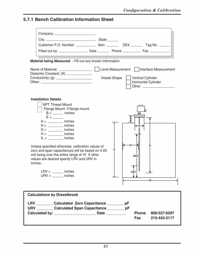
Configuration & Calibration
57
Appx-A-smh.pmd Page 0 of 1 Created 07/31/1997 by ELS Revised 08/07/2002 12:21 PM
Company
City State
Customer P.O. Number Item DE# Tag No.
Filled out by: Date Phone Fax
Material being Measured - Fill out any known information
Name of Material: Level Measurement Interface MeasurementDielectric Constant: (K)
Vessel Shape Vertical CylinderConductivity: (g)Horizontal CylinderOther:Other
Installation Details
NPT Thread Mount Flange Mount- if flange mount
B = inchesE =
A = inchesH = inchesD = inchesH = inchesIL = inches
Unless specified otherwise, calibration values ofzero and span capacitances will be based on 4-20mA being over the entire range of 'H'. If othervalues are desired specify LRV and URV ininches.
LRV = inchesURV = inches
A
E
H
B
D
IL
LRV
URV
Calculations by Drexelbrook
LRV ________ Calculated Zero Capacitance ________ pFURV ________ Calculated Span Capacitance ________ pFCalculated by: ____________________ Date _________ Phone 800-527-6297
Fax 215-443-5117
5.7.1 Bench Calibration Information Sheet

509-7X Series Universal III™ Transmitter
5
5.8 Point Calibration
Equipment Required:• UniversalIIIHART®SmartTransmitter• Model275HART®Calibrator• 24VPowersource• Approximately250ohmtotalloopresistance• Twoknownprocesslevelsappliedtotheprobe
Thisprocedureusesanexampleofapointcalibrationforfull-scale (20mA) = 35 ft. and zero (4mA) = 1.5 ft.
5.8.1 Fine Tuning Calibration
Whenaknownlevelisavailablethatisclosertoanendpointthanapreviouscalibrationpoint,itmaybeusedasanewcalibrationpointtoincreaseaccuracy.Thisisdoneinthefollowing steps: Enter the Upper Calibration Pointand/ or Enter the Lower Calibration Point with thenewknownlevelapplied.
The order of execution between the upper and lowercalibrationproceduresdoesnotmatter.Theycanbedoneatdifferenttimes.
TheprocedureSet Up Zero and Full Scale Limitsmustbe performed to set up the vessel zero and full-scale limits sometime prior to performing a point calibration. ThisinformstheUniversalIIIofthetanklevellimitsandonlyneedstobeperformedonceforagiveninstallation.
5.8.2 Selecting Engineering Units
The examples in this procedure use the default units offeet. For other units, use the following procedure:
A. Connect the handheld communicator to the 4-20 mAloopperFigure4-1.
B. Powertheloopandproceedwithfollowingsteps.Action View Function
1/0 Online (Generic) Power On1 Device Setup Select Device Setup3 Basic Setup Select Basic Setup4 PV Snsr unit Select PV Units⇑ & ⇓ Available Units Use the arrow keys to scroll
through the available units and press [ENTER] when the desired unit is displayed.
[ENTER] Basic Setup Select highlighted unitHome Online (Generic) Desired units are selected
Configuration & Calibration
59
5.9 Handheld Calibrator Error Messages
Error Message: Applied Process Too High Theappliedprocessat100%exceedsthecapacitancerange
settingbyatleast5%ofspan. Example: URV = 10 ft., Applied Process = 12 ft. will
generatethiserror. Action: TheSpanSelectJumperMustBeRaised. Thisallows theprocess outputat 100% tobewithin the
rangeofthespanrangecapacitance. Error Message: Span Too Small ThedifferencebetweentheURVandLRVislessthan10%
oftherange. Example: For 0 to 10 ft. calibration points: LRV = 3.0 ft.,
URV=3.8ft.willgeneratethiserror. Action: TheCalibrationPointsShouldBeFartherApart. When the calibration points are too close together, the
overallaccuracyofthecalibrationisadverselyaffected. Error Message: Upper Range Value Too High The process capacitance at 100% exceeds the present
capacitancerangejumpersetting. Example: For 0 to 10 ft. calibration: span select jumper =
100pF,pointcal.LRV=0ft.@10pF,URV=7ft.@90pFgeneratesthiserrorbecausetheprocesswouldbe124pF@10ft.
Action: TheSpanSelectJumperMustBeRaised. Thisallows theprocess outputat 100% tobewithin the
rangeofthespanrangecapacitance. NOTE: Respond to the prompt which is displayed immediately
after the error message that reads “Restore Device Value?” with <N>.
Error Message: Upper Range Value Too Low TheFullscaleprojected fromtheenteredURVandLRV
is less than5%of thepresent capacitance range jumpersetting.
Example: For 0 to 50 ft. calibration: span select jumper = 1000 pF, LRV = 0 ft. @ 10 pF, URV=40ft.@80pFgeneratesthiserror.
Action: TheSpanSelectJumperMustBeLowered. ThisallowstheURV-LRVspantobegreaterthan5%of
thecapacitancerangejumpersetting. NOTE: Respond to the prompt which is displayed immediately
after the error message that reads “Restore Device Value?” with <N>.

Section 6
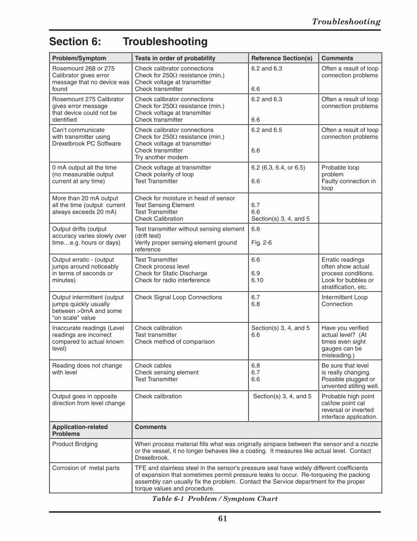
Troubleshooting
Problem/Symptom Tests in order of probability Reference Section(s) Comments
Rosemount 268 or 275 Calibrator gives error message that no device was found
Check calibrator connectionsCheck for 250Ω resistance (min.)Check voltage at transmitterCheck transmitter
6.2 and 6.3
6.6
Often a result of loop connection problems
Rosemount 275 Calibrator gives error message that device could not be identified
Check calibrator connectionsCheck for 250Ω resistance (min.)Check voltage at transmitterCheck transmitter
6.2 and 6.3
6.6
Often a result of loop connection problems
Can’t communicate with transmitter using Drexelbrook PC Software
Check calibrator connectionsCheck for 250Ω resistance (min.)Check voltage at transmitterCheck transmitterTry another modem
6.2 and 6.5
6.6
Often a result of loop connection problems
0 mA output all the time(no measurable output current at any time)
Check voltage at transmitterCheck polarity of loopTest Transmitter
6.2 (6.3, 6.4, or 6.5)
6.6
Probable loop problem Faulty connection in loop
More than 20 mA output all the time (output current always exceeds 20 mA)
Check for moisture in head of sensorTest Sensing ElementTest TransmitterCheck Calibration
6.76.6Section(s) 3, 4, and 5
Output drifts (output accuracy varies slowly over time…e.g. hours or days)
Test transmitter without sensing element (drift test)Verify proper sensing element ground reference
6.6
Fig. 2-6
Output erratic - (output jumps around noticeably in terms of seconds or minutes)
Test TransmitterCheck process levelCheck for Static DischargeCheck for radio interference
6.6
6.96.10
Erratic readings often show actual process conditions. Look for bubbles or stratification, etc.
Output intermittent (output jumps quickly usually between >0mA and some "on scale" value
Check Signal Loop Connections 6.76.8
Intermittent Loop Connection
Inaccurate readings (Level readings are incorrect compared to actual known level)
Check calibrationTest transmitterCheck method of comparison
Section(s) 3, 4, and 56.6
Have you verified actual level? (At times even sight gauges can be misleading.)
Reading does not change with level
Check cablesCheck sensing elementTest Transmitter
6.86.76.6
Be sure that level is really changing. Possible plugged or unvented stilling well.
Output goes in opposite direction from level change
Check calibration Section(s) 3, 4, and 5 Probable high point cal/low point cal reversal or inverted interface application.
Application-related Problems
Comments
Product Bridging When process material fills what was originally airspace between the sensor and a nozzle or the vessel, it no longer behaves like a coating. It measures like actual level. Contact Drexelbrook.
Corrosion of metal parts TFE and stainless steel in the sensor's pressure seal have widely different coefficients of expansion that sometimes permit pressure leaks to occur. Re-torqueing the packing assembly can usually fix the problem. Contact the Service department for the proper torque values and procedure.
Table 6-1 Problem / Symptom Chart
Section 6: Troubleshooting
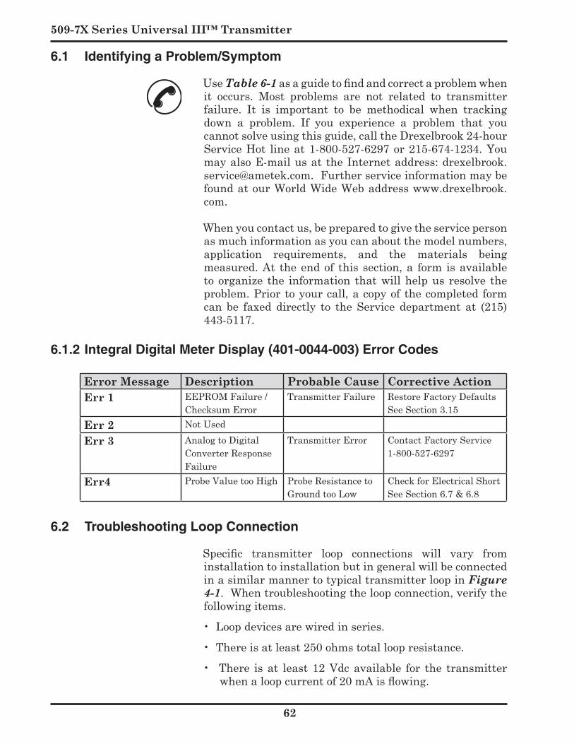
509-7X Series Universal III™ Transmitter
6.1.2 Integral Digital Meter Display (401-0044-003) Error Codes
Error Message Description Probable Cause Corrective ActionErr EEPROMFailure/
ChecksumErrorTransmitterFailure RestoreFactoryDefaults
SeeSection3.15Err NotUsed
Err AnalogtoDigitalConverterResponseFailure
TransmitterError ContactFactoryService1-800-527-6297
Err ProbeValuetooHigh ProbeResistancetoGroundtooLow
CheckforElectricalShortSeeSection6.7&6.8
6.1 Identifying a Problem/Symptom
UseTable 6-1 as a guide to find and correct a problem when it occurs. Most problems are not related to transmitterfailure. It is important to be methodical when trackingdown a problem. If you experience a problem that youcannotsolveusingthisguide,calltheDrexelbrook24-hourServiceHot lineat1-800-527-6297or215-674-1234.Youmay also E-mail us at the Internet address: drexelbrook.service@ametek.com.FurtherserviceinformationmaybefoundatourWorldWideWebaddresswww.drexelbrook.com.
Whenyoucontactus,bepreparedtogivetheservicepersonasmuchinformationasyoucanaboutthemodelnumbers,application requirements, and the materials beingmeasured.At theendof thissection,a form isavailableto organize the information that will help us resolve the problem.Priortoyourcall,acopyofthecompletedformcan be faxed directly to the Service department at (215)443-5117.
6.2 Troubleshooting Loop Connection
Specific transmitter loop connections will vary from installationtoinstallationbutingeneralwillbeconnectedinasimilarmannertotypicaltransmitterloopinFigure 4-1.Whentroubleshootingtheloopconnection,verifythefollowingitems.
•Loopdevicesarewiredinseries.
•Thereisatleast250ohmstotalloopresistance.
• There isat least12Vdcavailable for the transmitterwhen a loop current of 20 mA is flowing.
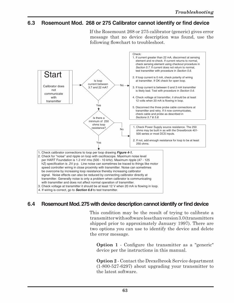
Troubleshooting
Is loopcurrent between3.7 and 22 mA?
Is there aminmum of 250
ohms loopresistance?
1. Check calibrator connections to loop per loop drawing Figure 4-1.2. Check for "noise" and ripple on loop with oscilloscope. Maximum noise level per HART Foundation is 1.2 mV rms (500 - 10 kHz). Maximum ripple (47 - 125 hZ) specification is .2V p-p. Line noise can sometimes be traced to things like motor speed controller wiring in close proximity with transmitter. Noise can sometimes be overcome by increasing loop resistance thereby increasing calibrator signal. Noise effects can also be reduced by connecting calibrator directly at transmitter. Generally noise is only a problem when calibrator is communicating with transmitter and does not affect normal operation of transmitter.3. Check voltage at transmitter it should be at least 12 V when 20 mA is flowing in loop.4. If wiring is correct, go to Section 6.6 to test transmitter.
Calibrator doesnot
communicatewith
transmitterYes
Yes
Check:1. If current greater than 22 mA, disconnect at sensing element and re-check. If current returns to normal, check sensing element using checkout procedure in Section 5.7. If current does not return to normal, test transmitter with procedure in Section 5.6.
2. If loop current is 0 mA, check polarity of wiring at transmitter. If OK check for open loop.
3. If loop current is between 0 and 3 mA transmitter is likely bad. Test with procedure in Section 5.6.
4. Check voltage at transmitter, it should be at least 12 volts when 20 mA is flowing in loop.
5. Disconnect the three probe cable connections at transmitter and retry. If it now communicates, check cable and probe as described in Sections 5.7 & 5.8.
1. Check Power Supply source resistance. The 250 ohms may be built in as with the Drexelbrook 401- 500 series or most DCS inputs.
2. If not, add enough resistance for loop to be at least 250 ohms.
Start
No
No
6.4 Rosemount Mod. 275 with device description cannot identify or find device
This condition may be the result of trying to calibrate atransmitterwithsoftwarelessthanversion3.0(transmittersshippedpriortoapproximatelyJanuary1997).Therearetwooptionsyoucanusetoidentifythedeviceanddeletetheerrormessage.
Option - Configure the transmitter as a "generic" devicepertheinstructionsinthismanual.
Option -ContacttheDrexelbrookServicedepartment(1-800-527-6297)aboutupgradingyour transmitter tothelatestsoftware.
6.3 Rosemount Mod. 268 or 275 Calibrator cannot identify or find device
IftheRosemount268or275calibrator(generic)giveserrormessage that no device description was found, use thefollowing flowchart to troubleshoot.
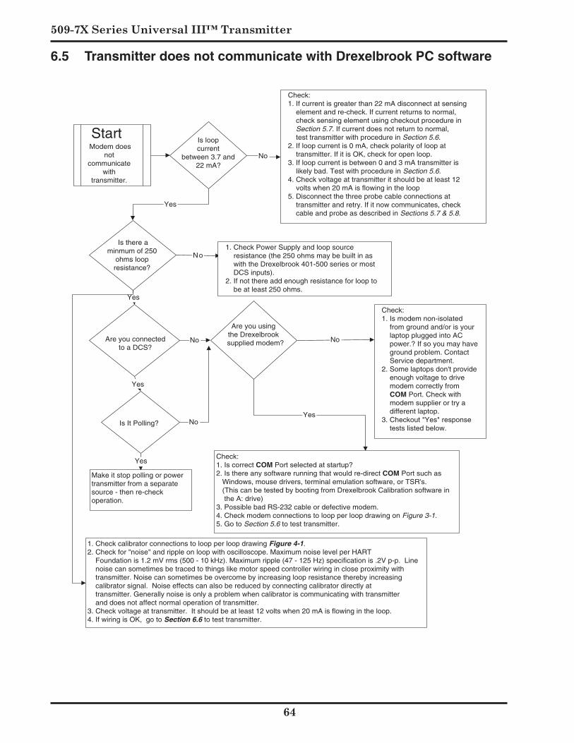
509-7X Series Universal III™ Transmitter
Is loopcurrent
between 3.7 and22 mA?
Is there aminmum of 250
ohms loopresistance?
Are you connectedto a DCS?
Is It Polling?
Make it stop polling or powertransmitter from a separatesource - then re-checkoperation.
Yes
Yes
YesCheck:1. Is correct COM Port selected at startup?2. Is there any software running that would re-direct COM Port such as Windows, mouse drivers, terminal emulation software, or TSR's. (This can be tested by booting from Drexelbrook Calibration software in the A: drive)3. Possible bad RS-232 cable or defective modem.4. Check modem connections to loop per loop drawing on Figure 3-1.5. Go to Section 5.6 to test transmitter.
Modem doesnot
communicatewith
transmitter.
No
No
Start
No
Are you usingthe Drexelbrooksupplied modem?
Check:1. Is modem non-isolated from ground and/or is your laptop plugged into AC power.? If so you may have ground problem. Contact Service department.2. Some laptops don't provide enough voltage to drive modem correctly from
COM Port. Check with modem supplier or try a
different laptop.3. Checkout "Yes" response tests listed below.
No
Yes
Check:1. If current is greater than 22 mA disconnect at sensing element and re-check. If current returns to normal, check sensing element using checkout procedure in Section 5.7. If current does not return to normal, test transmitter with procedure in Section 5.6.2. If loop current is 0 mA, check polarity of loop at transmitter. If it is OK, check for open loop.3. If loop current is between 0 and 3 mA transmitter is likely bad. Test with procedure in Section 5.6.4. Check voltage at transmitter it should be at least 12 volts when 20 mA is flowing in the loop5. Disconnect the three probe cable connections at transmitter and retry. If it now communicates, check cable and probe as described in Sections 5.7 & 5.8.
No
Yes
1. Check Power Supply and loop source resistance (the 250 ohms may be built in as with the Drexelbrook 401-500 series or most DCS inputs).2. If not there add enough resistance for loop to be at least 250 ohms.
1. Check calibrator connections to loop per loop drawing Figure 4-1.2. Check for "noise" and ripple on loop with oscilloscope. Maximum noise level per HART Foundation is 1.2 mV rms (500 - 10 kHz). Maximum ripple (47 - 125 Hz) specification is .2V p-p. Line noise can sometimes be traced to things like motor speed controller wiring in close proximity with transmitter. Noise can sometimes be overcome by increasing loop resistance thereby increasing calibrator signal. Noise effects can also be reduced by connecting calibrator directly at transmitter. Generally noise is only a problem when calibrator is communicating with transmitter and does not affect normal operation of transmitter.3. Check voltage at transmitter. It should be at least 12 volts when 20 mA is flowing in the loop.4. If wiring is OK, go to Section 6.6 to test transmitter.
6.5 Transmitter does not communicate with Drexelbrook PC software
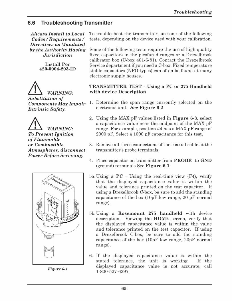
Troubleshooting
5
6.6 Troubleshooting Transmitter
Totroubleshootthetransmitter,useoneofthefollowingtests,dependingonthedeviceusedwithyourcalibration.Someofthefollowingtestsrequiretheuseofhighqualityfixed capacitors in the picofarad ranges or a Drexelbrook calibratorbox (C-box401-6-81).Contact theDrexelbrookServicedepartmentifyouneedaC-box.Fixedtemperaturestablecapacitors(NPOtypes)canoftenbefoundatmanyelectronicsupplyhouses.
TRANSMITTER TEST - Using a PC or 75 Handheld with device Description
1. Determine the span range currently selected on theelectronicunit.See Figure -
2. UsingtheMAXpFvalueslistedinFigure -,selectacapacitancevaluenearthemidpointoftheMAXpFrange.Forexample,position#4hasaMAXpFrangeof2000pF.Selecta1000pFcapacitanceforthistest.
3. Removeallthreeconnectionsofthecoaxialcableatthetransmitter'sprobeterminals.
4. PlacecapacitorontransmitterfromPROBEtoGND(ground)terminalsSeeFigure -.
5a.Using a PC - Using the real-time view (F4), verifythat the displayed capacitance value is within thevalue and tolerance printed on the test capacitor. IfusingaDrexelbrookC-box,besuretoaddthestandingcapacitanceofthebox(10pFlowrange,20pFnormalrange).
5b.Using a Rosemount 75 handheld with devicedescription - Viewing the HOME screen, verify thatthe displayed capacitance value is within the valueand tolerance printed on the test capacitor. If usinga Drexelbrook C-box, be sure to add the standingcapacitanceof thebox (10pF lowrange,20pFnormalrange).
6. If the displayed capacitance value is within thestated tolerance, the unit is working. If thedisplayed capacitance value is not accurate, call1-800-527-6297.
Always Install to Local Codes / Requirements /
Directives as Mandated by the Authority Having
Jurisdiction
Install Per 0-000-0-ID
WARNING: Substitution of Components May Impair Intrinsic Safety.
WARNING: To Prevent Ignition of Flammable or Combustible Atmospheres, disconnect Power Before Servicing.
Figure 6-1
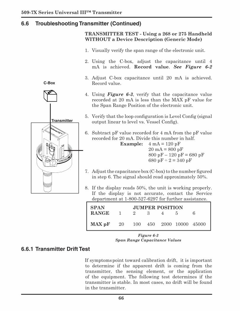
509-7X Series Universal III™ Transmitter
TRANSMITTER TEST - Using a or 75 Handheld WITHOUT a Device Description (Generic Mode)
1. Visuallyverifythespanrangeoftheelectronicunit.
2. Using the C-box, adjust the capacitance until 4mA is achieved. Record value. See Figure 6-2
3. Adjust C-box capacitance until 20 mA is achieved.Recordvalue.
4. Using Figure 6-3, verify that the capacitance valuerecordedat20mAis lessthantheMAXpFvalue fortheSpanRangePositionoftheelectronicunit.
5. Verify that the loop configuration is Level Config (signal output linear to level vs. Vessel Config).
6. SubtractpFvaluerecordedfor4mAfromthepFvalue
recordedfor20mA.Dividethisnumberinhalf. Example: 4mA=120pF 20mA=800pF 800pF–120pF=680pF 680pF÷2=340pF
7. Adjust the capacitance box (C-box) to the number figured instep6.Thesignalshouldreadapproximately50%.
8. Ifthedisplayreads50%,theunitisworkingproperly.If the display is not accurate, contact the Servicedepartmentat1-800-527-6297forfurtherassistance.
SPAN JUMPER POSITIONRANGE 1 2 3 4 5 6
MAX pF 20 100 450 2000 10000 45000
Figure 6-3 Span Range Capacitance Values
6.6 Troubleshooting Transmitter (Continued)
6.6.1 Transmitter Drift Test
Ifsymptomspointtowardcalibrationdrift,itisimportantto determine if the apparent drift is coming from thetransmitter, the sensing element, or the applicationof the equipment. The following test determines if thetransmitterisstable.Inmostcases,nodriftwillbefoundinthetransmitter.
Figure 6-2
C-Box
Transmitter
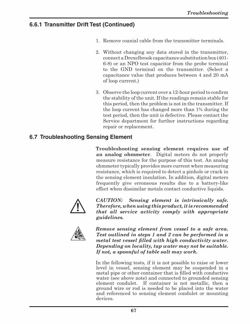
Troubleshooting
7
1. Removecoaxialcablefromthetransmitterterminals.
2. Withoutchanginganydatastored inthetransmitter,connectaDrexelbrookcapacitancesubstitutionbox(401-6-8)oranNPOtestcapacitorfromtheprobeterminalto the GND terminal on the transmitter. (Select acapacitancevaluethatproducesbetween4and20mAofloopcurrent.)
3. Observe the loop current over a 12-hour period to confirm thestabilityoftheunit.Ifthereadingsremainstableforthisperiod,thentheproblemisnotinthetransmitter.Iftheloopcurrenthaschangedmorethan1%duringthetestperiod,thentheunitisdefective.PleasecontacttheServicedepartment for further instructions regardingrepairorreplacement.
6.7 Troubleshooting Sensing Element
Troubleshooting sensing element requires use of an analog ohmmeter. Digital meters do not properlymeasureresistanceforthepurposeofthistest.Ananalogohmmetertypicallyprovidesmorecurrentwhenmeasuringresistance,whichisrequiredtodetectapinholeorcrackinthesensingelementinsulation.Inaddition,digitalmetersfrequently give erroneous results due to a battery-likeeffectwhendissimilarmetalscontactconductiveliquids.
CAUTION: Sensing element is intrinsically safe. Therefore, when using this product, it is recommended that all service activity comply with appropriate guidelines.
Remove sensing element from vessel to a safe area. Test outlined in steps 1 and 2 can be performed in a metal test vessel filled with high conductivity water. Depending on locality, tap water may not be suitable. If not, a spoonful of table salt may work.
Inthefollowingtests,ifitisnotpossibletoraiseorlowerlevel in vessel, sensing element may be suspended in ametal pipe or other container that is filled with conductive water(seeabovenote)andconnectedtogroundedsensingelement condulet. If container is not metallic, then agroundwireorrodisneededtobeplacedintothewaterand referenced to sensingelement condulet ormountingdevices.
6.6.1 Transmitter Drift Test (Continued)
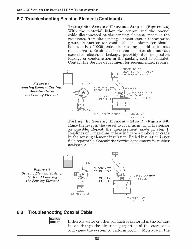
509-7X Series Universal III™ Transmitter
Testing the Sensing Element - Step (Figure -5)With the material below the sensor, and the coaxialcable disconnected at the sensing element, measure theresistance from the sensing element center connector toground connector (or condulet). The ohmmeter shouldbe set to R x 10000 scale. The reading should be infinite (opencircuit).Readingsoflessthanonemeg-ohmindicateexcessive electrical leakage, probably due to productleakageor condensation in thepacking seal or condulet.ContacttheServicedepartmentforrecommendedrepairs.
Testing the Sensing Element - Step (Figure -)
Raisethelevelinthevesseltocoverasmuchofthesensoras possible. Repeat the measurement made in step 1.Readingsof1meg-ohmorlessindicateapinholeorcrackinthesensingelementinsulation.Failedinsulationisnotfield repairable. Consult the Service department for further assistance.
6.8 Troubleshooting Coaxial Cable
Ifthereiswaterorotherconductivematerialintheconduitit can change the electrical properties of the coax cableandcausethesystemtoperformpoorly.Moistureinthe
Figure 6-5 Sensing Element Testing,
Material Belowthe Sensing Element
Figure 6-6 Sensing Element Testing,
Material Covering the Sensing Element
6.7 Troubleshooting Sensing Element (Continued)
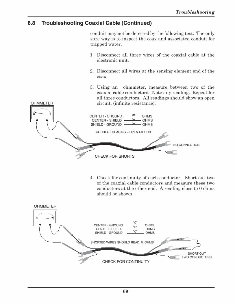
Troubleshooting
9
conduitmaynotbedetectedbythefollowingtest.Theonlysurewayistoinspectthecoaxandassociatedconduitfortrappedwater.
1. Disconnect all three wires of the coaxial cable at theelectronicunit.
2. Disconnectallwiresatthesensingelementendofthecoax.
3. Using an ohmmeter, measure between two of thecoaxialcableconductors.Noteanyreading.Repeatforallthreeconductors.Allreadingsshouldshowanopencircuit, (infinite resistance).
SHORT OUTTWO CONDUCTORS
CENTER - GROUND CENTER - SHIELD SHIELD - GROUND
OHMS OHMS OHMS
SHORTED WIRES SHOULD READ 0 OHMS
CHECK FOR CONTINUITY
8
0
"0""0""0"
OHMMETER
4. Checkforcontinuityofeachconductor.Shortouttwoofthecoaxialcableconductorsandmeasurethesetwoconductorsattheotherend.Areadingcloseto0ohmsshouldbeshown.
6.8 Troubleshooting Coaxial Cable (Continued)

509-7X Series Universal III™ Transmitter
70
6.9 Static Electricity
Staticelectricitycancausethe4-20mAoutputtoappeartojumparoundinanerraticfashionwithatimeperiodoffewseconds. Applications that are prone to static electricityincludeinsulatingliquidsthatmaybeagitatedorpumpedandgranularsthatmaybeair-conveyedathighratesofspeed.Conductiveliquidsandconductivegranularstendnottogeneratestaticelectricity. Inadditionto causingerratic readings, static electricity can cause instrumentfailure. If you ever get a static shock from a sensingelement, you need spark protection. (See section 2.5)
Drexelbrooknormallysuppliesstaticelectricitydischargedevices (sparkprotectors)with itssensingelements thataregoingtobeusedinthesetypesofapplications.Ifyouneed a spark protector, contact the Drexelbrook Servicedepartment.
6.10 Radio Frequency Interference
All Drexelbrook transmitters have a significant amount ofRFIprotectionbuiltin.Therearesituations,however,where the standard protection is inadequate. RFI filters areavailabletoprovideadditionalprotectionforboththesensor and the 4-20 mA loop from unusually difficult sources ofinterference.Propergroundingandcarefulattentiontoinstallationpracticescanusuallymakethemunnecessary.Some recommended installation practices include:
1.Usetwistedshieldedcableforthe4-20mAloop.2.Use grounded metal conduit for all entrances to the
transmitterhousing.3.Ground the transmitter housing to a good earth
ground.4.Useconcentricshieldsensorsinnon-metallicvessels.
IfRFIcontinuestobeaproblem,contacttheDrexelbrookservice department for the proper filters and assistance.
6.11 Factory Assistance
AMETEK Drexelbrook can answer any questions aboutyourlevelmeasurementsystem.
For Technical Support: 1-800-527-6297 All other inquiries: Call Customer Service at
1-800-553-9092 (US and Canada) , or + 215-674-1234(International).
Troubleshooting
7
Ifyourequireassistanceandattemptstolocatetheproblemhave failed:
•ContactyourlocalDrexelbrookrepresentative,
• For Technical Assistance call toll-free: 1-800-527-6297 (US and Canada) or + 215-674-1234
(International),
• FAX: + 215-443-5117,
• E-mail: [email protected] Please provide the following information:
• InstrumentModelNumber
• SensingElementModelNumberandLength
• OriginalPurchaseOrder
• Materialbeingmeasured • Temperature • Pressure • Agitation
• Briefdescriptionoftheproblem
• Checkoutproceduresthathavefailed
6.12 Field Service Trained field servicemen are available on a time-plus-
expense basis to assist in start-ups, diagnosing difficult application problems, or in-plant training of personnel.Contacttheservicedepartmentforfurtherdetails.
6.13 Customer Training Periodically, AMETEK Drexelbrook instrument training
seminars for customers are held at the factory. Thesesessions are guided by Drexelbrook engineers andspecialists,andprovidedetailedinformationonallaspectsof level measurement, including theory and practice ofinstrument operation. For more information about thesevaluable workshops, write to AMETEK Drexelbrook,attention: Communications/ Training Group, or call direct +215-674-1234.
6.11 Factory Assistance (Continued)
509-7X Series Universal III™ Transmitter
7
6.14 Return Equipment
Any equipment being returned for repair or credit must be pre-approved by the factory.
In many applications, sensing elements are exposed tohazardous materials.
•OSHAmandates thatouremployeesbe informedandprotected from hazardous chemicals.
•Material Safety Data Sheets (MSDS) listing thehazardous materials to which the sensing element has beenexposedMUSTaccompanyanyrepair.
•Itisyourresponsibilitytofullydiscloseallchemicalsanddecontaminatethesensingelement.
To obtain a return authorization (RA#), contact the Service departmentat1-800-527-6297(USandCanada)or+215-674-1234(International).
Please provide the following information:
• ModelNumberofReturnEquipment • SerialNumber • OriginalPurchaseOrderNumber • Process Materials to which equipment has been
exposed • MSDS sheets for any hazardous materials• BillingAddress• ShippingAddress• PurchaseOrderNo.forRepairs Please include a purchase order even if the repair is under
warranty. If repair is covered under warranty, you will not be charged.
Ship equipment freight prepaid to: AMETEKDrexelbrook 205KeithValleyRoad Horsham,PA19044-1499
CODshipmentswillnotbeaccepted.
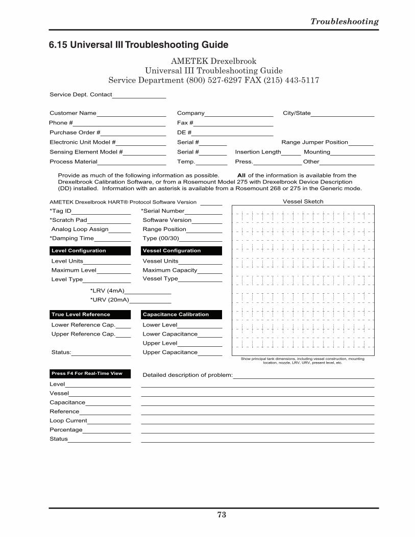
Troubleshooting
7
AMETEK Drexelbrook™Universal III Mark II Troubleshooting Guide
Service Department (800) 527-6297 FAX(215) 443-5117
Service Dept. Contact
*Tag ID
*Scratch Pad
Analog Loop Assign
*Damping Time
Level Units
Maximum Level
Level Type
Level Configuration Vessel Configuration
Vessel Units
Maximum Capacity
Vessel Type
True Level Reference
Lower Reference Cap.
Upper Reference Cap.
Capacitance Calibration
Lower Level
Lower Capacitance
Upper Level
Upper Capacitance Status:
*Serial Number
Software Version
Range Position
AMETEK Drexelbrook HART® Protocol Software Version
Detailed description of problem:
Level
Vessel
Capacitance
Reference
Loop Current
Percentage
Status
Press F4 For Real-Time View
Type (00/30)
*LRV (4mA)
*URV (20mA)
Vessel Sketch
Show principal tank dimensions, including vessel construction, mountinglocation, nozzle, LRV, URV, present level, etc.
Provide as much of the following information as possible. All of the information is available from theDrexelbrook Calibration Software, or from a Rosemount Model 275 with Drexelbrook Device Description(DD) installed. Information with an asterisk is available from a Rosemount 268 or 275 in the Generic mode.
Electronic Unit Model # Serial # Range Jumper Position
Sensing Element Model # Serial # Insertion Length Mounting
Process Material Temp. Press. Other
Customer Name Company
Phone # Fax #
City/State
Purchase Order # DE #
6.15 Universal III Troubleshooting Guide
AMETEKDrexelbrookUniversalIIITroubleshootingGuide
ServiceDepartment(800)527-6297FAX(215)443-5117

Section 7
Specifications
75
Section 7: Specifications
7.1 Transmitter Specifications
Power Requirement • 12to50VDC• Minimumof12VDCat20mA
Input Range• 409-1000: 1.0 to 45,000 pF
Output Range• 4-20mA
Accuracy• ±0.25%ofrange.Accuracyincludesthecombinedeffects
of linearity, hysteresis, and repeatability. It refersto the transmitter only and is measured at referenceconditions of 25 degrees C ±1°, 10-55% R.H. and 24±1.2Vdc,usinganadmittancestandard(appliedtothetransmittersensorterminals)inplaceofthesensor.
Load Resistance• MaximumLoadResistance=750ohms• MinimumLoadResistance=250ohms
Temperature Effect• ±1%ofrangeper50°F(30°C).
Supply Voltage Effect• <0.1%from12to50VDC.
Effect of Load Resistance• <0.1%forfullresistancerangeat24VDCsupply.
Response to Step Change• < 1 second standard (to 90% of final value); 0-90secondsavailablewithdelay.
Fail-Safe• Low-LevelFail-Safe(LLFS)standard. Also called direct-acting because current increases as
thelevelincreases.• High-levelFail-Safe(HLFS). Alsocalledreverse-actingbecausecurrentdecreasesas
levelincreases.
ThereAreNoDevicesThatAreAbsolutely“Fail-Safe".Fail-safe means that in the event of the most probable failures, the instruments will fail safely. Probable failures include things such as loss of power and transistor and component failures. If your application needs absolute fail-safe, a back-up instrument should be installed.
509-7X Series Universal III™ Transmitter
7
7.1 Transmitter Specifications (Continued)
Ambient Temperature• -40°Fto+185°F(-40°Cto85°C)
Calibration Adjustments• RangeSpan,6positions(sidepanel)
Lowest Permitted Resistance (baresensingelementtoground)causing5%errorineach
model: • 600ohms-409-1000• 100Kohms-409-1030
Intrinsic Safety• Sensing element and cable: Designed to be intrinsically
safeforClassIGroupsA,B,CandD;ClassIIGroupsE,F,andG,(ClassIII,Div.1).Electronicsandsignalwires: Intrinsically safe for Class I Groups A, B, C, and D,ClassIIGroupsE,FandG(Div.1)whenpoweredbyanintrinsicallysafepowersupply.NonincendiveforClassIGroupsA,B,C,andD;ClassIIGroupsE,F,andG,ClassIII,(Div.2).
Sensing Element Cable Length• 100feetmaximum.
7.2 Coaxial Cable Specifications
Sensing Element Cable Length 150feetmaximum.
General Purpose 380-XXX-12 .51"(13mm)ODatlargestpoint, 160°F(70°C)temperaturelimit.
Composite Cable 0-XXX- (first 10 feet high temperature) .62"(16mm)ODatlargestpoint,450°F (230°C) temperature limit for first 10 feet. 160°F(70°C)temperaturelimitforremainder.
High Temperature Cable 0-XXX- .51"(13mm)ODatlargestpoint, 450°F(230°C)temperaturelimit.
Normal Maintenance
77
Section 8: Normal Maintenance
8.1 Viewport Cleaning
Theviewport(ifsupplied)ismadeofBorosilicateglassandcan be cleaned with any common glass cleaning product(e.g.: Windex™, Isopropyl alcohol, etc.) that is suitable for the Class and Division rating of the specific system installation.

Section 9
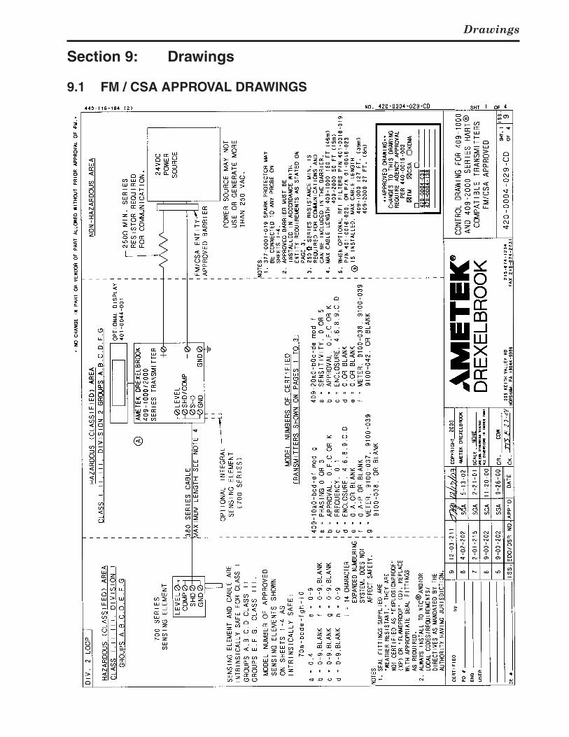
Drawings
79
Section 9: Drawings
9.1 FM / CSA APPROVAL DRAWINGS
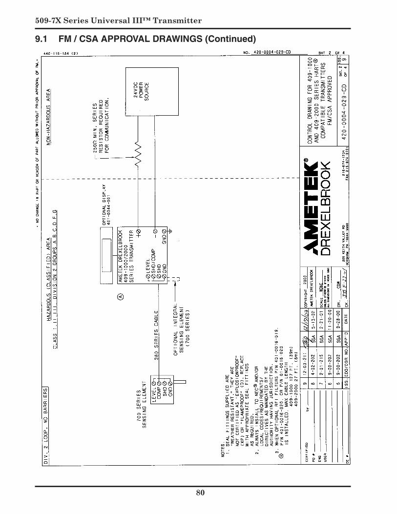
509-7X Series Universal III™ Transmitter
0
9.1 FM / CSA APPROVAL DRAWINGS (Continued)
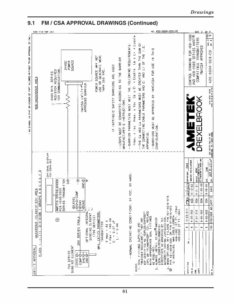
Drawings
9.1 FM / CSA APPROVAL DRAWINGS (Continued)
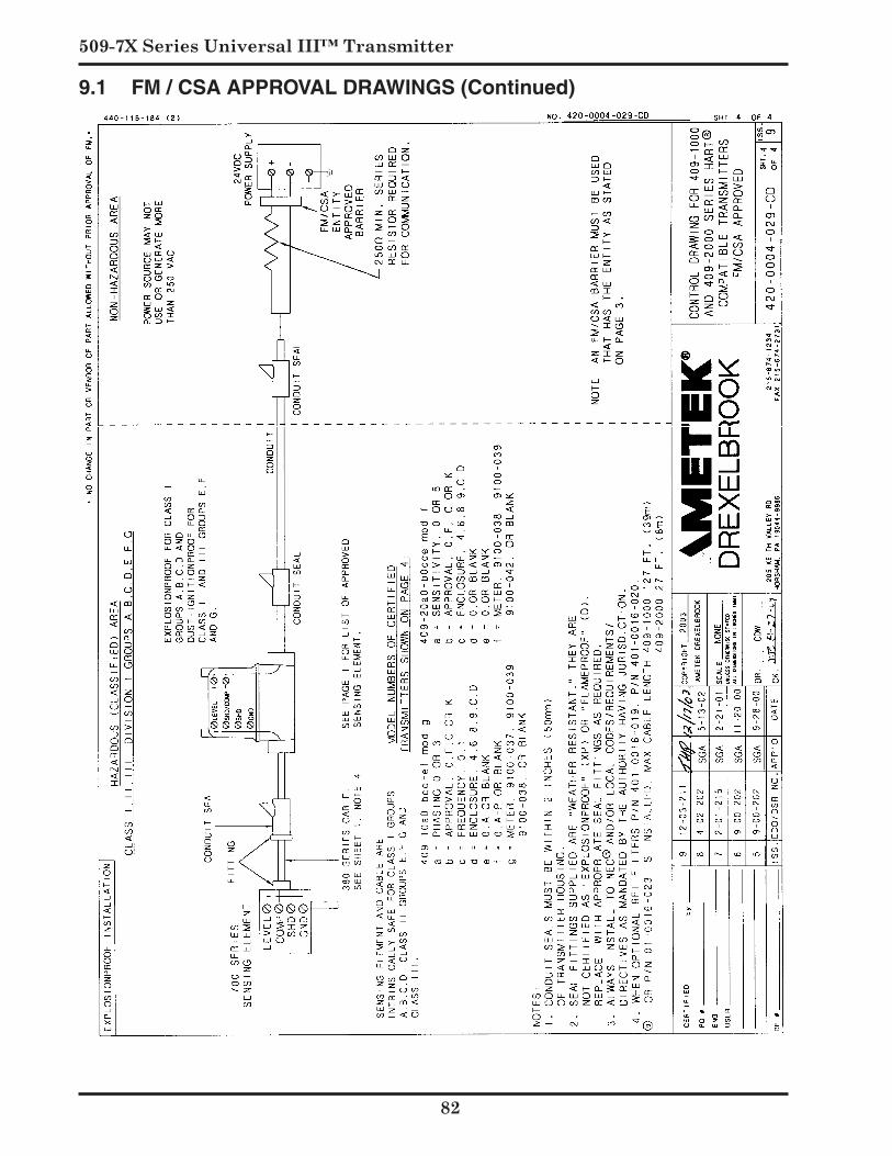
509-7X Series Universal III™ Transmitter
9.1 FM / CSA APPROVAL DRAWINGS (Continued)
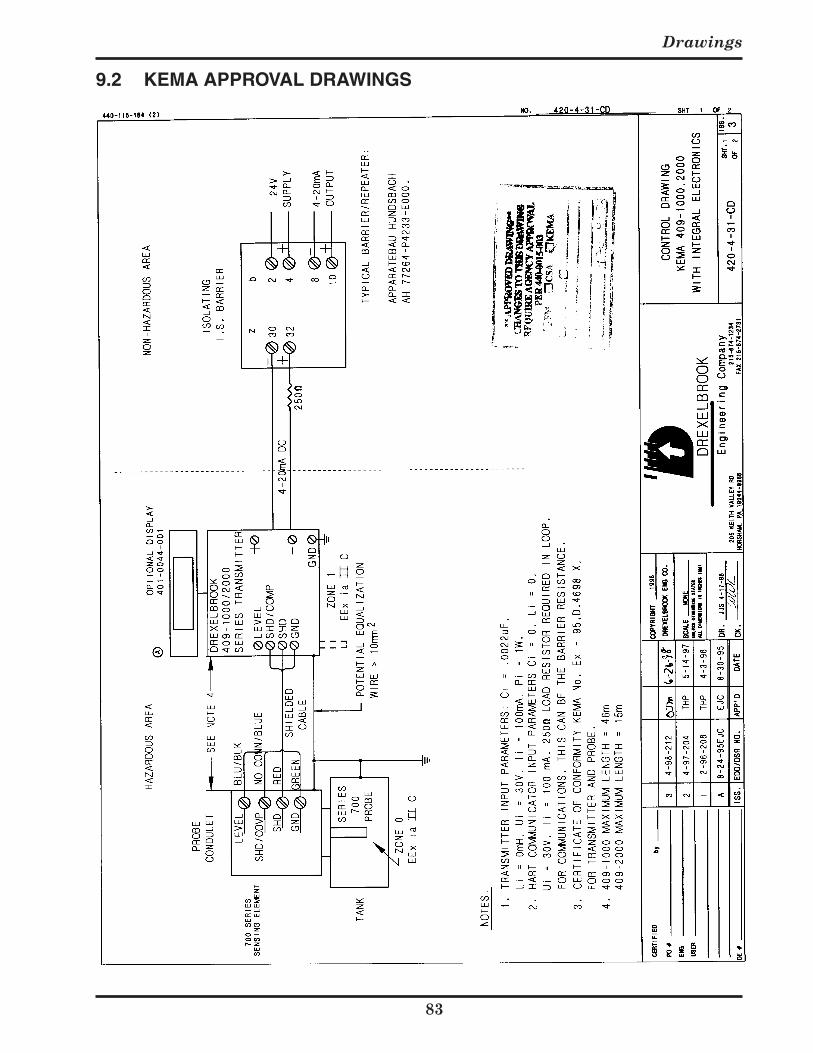
Drawings
9.2 KEMA APPROVAL DRAWINGS
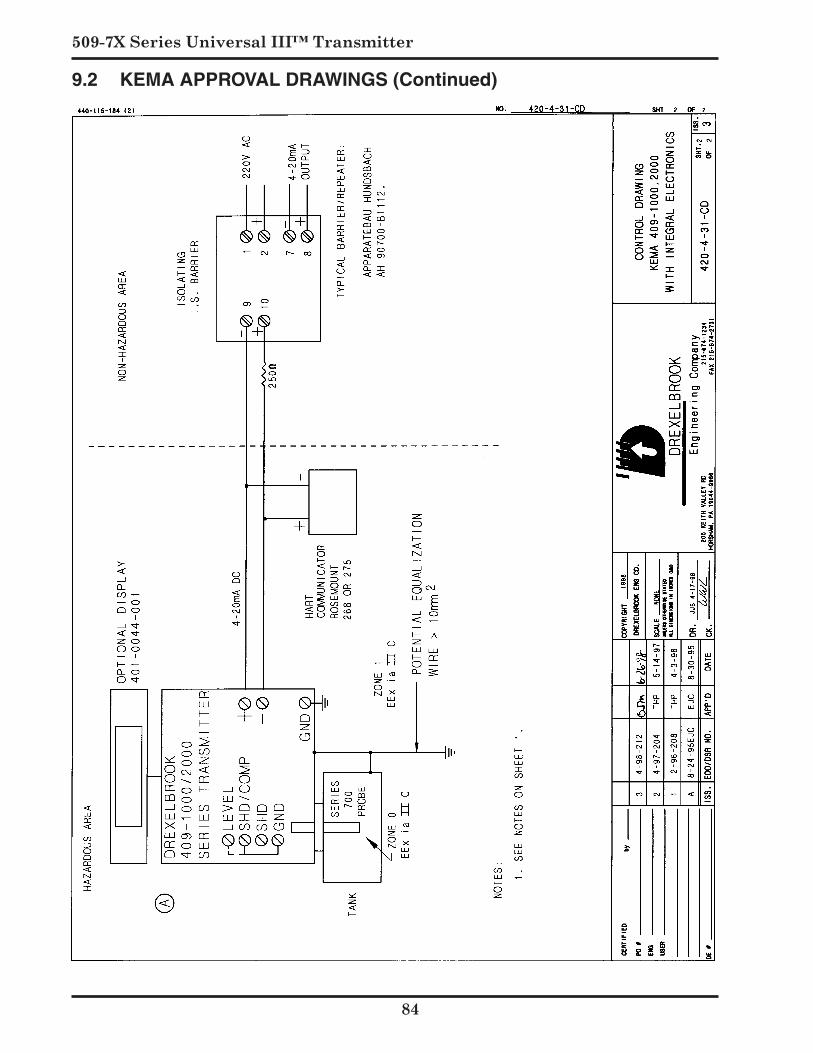
509-7X Series Universal III™ Transmitter
9.2 KEMA APPROVAL DRAWINGS (Continued)


205 Keith Valley Road, Horsham, PA 19044 U.S. and Canada: 1-800-553-909224-Hour Service: 1-800-527-6297International: +1 215-674-1234Fax: +1 215-674-2731E-mail: [email protected] Website: www.drexelbrook.com
An ISO 9001 Certified Company
Recommended