Data Center: Infrastructure Architecture SRNDSolutions Reference Network DesignMarch, 2004
Corporate HeadquartersCisco Systems, Inc.170 West Tasman DriveSan Jose, CA 95134-1706 USAhttp://www.cisco.comTel: 408 526-4000
800 553-NETS (6387)Fax: 408 526-4100
Customer Order Number: 956513

THE SPECIFICATIONS AND INFORMATION REGARDING THE PRODUCTS IN THIS MANUAL ARE SUBJECT TO CHANGE WITHOUT NOTICE. ALL STATEMENTS, INFORMATION, AND RECOMMENDATIONS IN THIS MANUAL ARE BELIEVED TO BE ACCURATE BUT ARE PRESENTED WITHOUT WARRANTY OF ANY KIND, EXPRESS OR IMPLIED. USERS MUST TAKE FULL RESPONSIBILITY FOR THEIR APPLICATION OF ANY PRODUCTS.
THE SOFTWARE LICENSE AND LIMITED WARRANTY FOR THE ACCOMPANYING PRODUCT ARE SET FORTH IN THE INFORMATION PACKET THAT SHIPPED WITH THE PRODUCT AND ARE INCORPORATED HEREIN BY THIS REFERENCE. IF YOU ARE UNABLE TO LOCATE THE SOFTWARE LICENSE OR LIMITED WARRANTY, CONTACT YOUR CISCO REPRESENTATIVE FOR A COPY.
The Cisco implementation of TCP header compression is an adaptation of a program developed by the University of California, Berkeley (UCB) as part of UCB’s public domain version of the UNIX operating system. All rights reserved. Copyright © 1981, Regents of the University of California.
NOTWITHSTANDING ANY OTHER WARRANTY HEREIN, ALL DOCUMENT FILES AND SOFTWARE OF THESE SUPPLIERS ARE PROVIDED “AS IS” WITH ALL FAULTS. CISCO AND THE ABOVE-NAMED SUPPLIERS DISCLAIM ALL WARRANTIES, EXPRESSED OR IMPLIED, INCLUDING, WITHOUT LIMITATION, THOSE OF MERCHANTABILITY, FITNESS FOR A PARTICULAR PURPOSE AND NONINFRINGEMENT OR ARISING FROM A COURSE OF DEALING, USAGE, OR TRADE PRACTICE.
IN NO EVENT SHALL CISCO OR ITS SUPPLIERS BE LIABLE FOR ANY INDIRECT, SPECIAL, CONSEQUENTIAL, OR INCIDENTAL DAMAGES, INCLUDING, WITHOUT LIMITATION, LOST PROFITS OR LOSS OR DAMAGE TO DATA ARISING OUT OF THE USE OR INABILITY TO USE THIS MANUAL, EVEN IF CISCO OR ITS SUPPLIERS HAVE BEEN ADVISED OF THE POSSIBILITY OF SUCH DAMAGES.
Data Cemter Networking: Enterprise Distributed Data CentersCopyright © 2004, Cisco Systems, Inc.All rights reserved.
CCIP, CCSP, the Cisco Arrow logo, the Cisco Powered Network mark, Cisco Unity, Follow Me Browsing, FormShare, and StackWise are trademarks of Cisco Systems, Inc.; Changing the Way We Work, Live, Play, and Learn, and iQuick Study are service marks of Cisco Systems, Inc.; and Aironet, ASIST, BPX, Catalyst, CCDA, CCDP, CCIE, CCNA, CCNP, Cisco, the Cisco Certified Internetwork Expert logo, Cisco IOS, the Cisco IOS logo, Cisco Press, Cisco Systems, Cisco Systems Capital, the Cisco Systems logo, Empowering the Internet Generation, Enterprise/Solver, EtherChannel, EtherSwitch, Fast Step, GigaStack, Internet Quotient, IOS, IP/TV, iQ Expertise, the iQ logo, iQ Net Readiness Scorecard, LightStream, MGX, MICA, the Networkers logo, Networking Academy, Network Registrar, Packet, PIX, Post-Routing, Pre-Routing, RateMUX, Registrar, ScriptShare, SlideCast, SMARTnet, StrataView Plus, Stratm, SwitchProbe, TeleRouter, The Fastest Way to Increase Your Internet Quotient, TransPath, and VCO are registered trademarks of Cisco Systems, Inc. and/or its affiliates in the U.S. and certain other countries.
All other trademarks mentioned in this document or Web site are the property of their respective owners. The use of the word partner does not imply a partnership relationship between Cisco and any other company. (0304R)
956513
C O N T E N T S
Preface vii
Document Purpose vii
Document Organization viii
Obtaining Documentation viiiWorld Wide Web viiiDocumentation CD-ROM viiiOrdering Documentation ixDocumentation Feedback ix
Obtaining Technical Assistance ixCisco.com ixTechnical Assistance Center x
Cisco TAC Web Site xCisco TAC Escalation Center xi
C H A P T E R 1 Data Center Infrastructure Architecture 1-1
Data Center Architecture 1-1
Hardware and Software Recommendations 1-3Aggregation Switches 1-3Service Appliances 1-5Service Modules 1-5Access Switches 1-6Software Recommendations 1-8
Data Center Multi-Layer Design 1-9Core Layer 1-9Aggregation and Access Layer 1-10Service Switches 1-10Server Farm Availability 1-11Load-Balanced Servers 1-12
Data Center Protocols and Features 1-15Layer 2 Protocols 1-15Layer 3 Protocols 1-16Security in the Data Center 1-18
Scaling Bandwidth 1-18
Network Management 1-19
iiiData Center: Infrastructure Architecture SRND
Contents
1-20
C H A P T E R 2 Data Center Infrastructure Design 2-1
Routing Between the Data Center and the Core 2-1Layer 3 Data Center Design 2-1Using OSPF 2-3Using EIGRP 2-7Designing Layer 3 Security 2-8
Switching Architecture for the Server Farm 2-9Using Redundant Supervisors 2-9Layer 2 Data Center Design 2-10
Using Three-Tier and Two-Tier Network Designs 2-10Layer 2 and Layer 3 Access Design 2-11Using VLANs to Segregate Server Farms 2-12VLAN Scalability 2-13Using Virtual Trunking Protocol 2-14Choosing a Spanning-Tree Algorithm 2-14Using Loopguard and UDLD 2-15Using PortFast and TrunkFast 2-17Using a Loop-Free Topology 2-18Designing Layer 2 Security 2-19
Assigning the Default Gateway in the Data Center 2-21Using Gateway Redundancy Protocols 2-22Tuning the ARP Table 2-23
C H A P T E R 3 HA Connectivity for Servers and Mainframes: NIC Teaming and OSA/OSPF Design 3-1
Overview 3-1Ensuring Server Farm and Mainframe Availability 3-2Load Balanced Servers 3-4NIC Teaming 3-4Mainframe Sysplex 3-6
NIC Teaming Architecture Details 3-7Hardware and Software 3-8Deployment Modes 3-8
Fault Tolerance Modes 3-8Load Balancing Modes 3-12Link Aggregation Modes 3-13Layer 3 Multihoming 3-14
Interoperability with Security 3-16
ivData Center: Infrastructure Architecture SRND
956513
Contents
Intrusion Detection 3-17Port Security 3-17Private VLANs 3-19
Mainframe OSA and OSPF Architecture Details 3-20Overview 3-20Attachment Options 3-21IP Addressing 3-22OSPF Routing on a Mainframe 3-23Sysplex 3-24
Configuration Details 3-26Speed and Duplex Settings 3-27Layer 2 Implementation 3-27
Spanning Tree 3-27PortFast and BPDU Guard 3-28Port Security 3-29Server Port Configuration 3-29
C H A P T E R 4 Data Center Infrastructure Configuration 4-1
Configuring Network Management 4-1Username and Passwords 4-1VTY Access 4-2SNMP 4-3Logging 4-3
VLAN Configuration 4-3
Spanning Tree Configuration 4-6Rapid PVST+ 4-6MST 4-7Protection From Loops 4-7
VLAN Interfaces and HSRP 4-8
Switch-To-Switch Connections Configuration 4-9Channel Configuration 4-9Trunk Configuration 4-10
Server Port Configuration 4-12Speed and Duplex Settings 4-12PortFast and BPDU Guard 4-13Port Security 4-13Configuration Example 4-14
Sample Configurations 4-14Aggregation1 4-14
vData Center: Infrastructure Architecture SRND
956513

Contents
Aggregation2 4-18Access 4-21
G L O S S A R Y
I N D E X
viData Center: Infrastructure Architecture SRND
956513

Preface
This publication provides solution guidelines for enterprises implementing Data Centers with Cisco devices. The intended audiences for this design guide include network architects, network managers, and others concerned with the implementation of secure Data Center solutions, including:
• Cisco sales and support engineers
• Cisco partners
• Cisco customers
Document PurposeThe convergence of voice and video in today’s enterprise networks has placed additional requirements on the infrastructure of enterprise data centers, which must provide the following services:
• Hosting enterprise-wide servers
• Supporting critical application services
• Supporting traditional data services
• 24X7 availability
These requirements are based on the applications supported rather than the size of the data center. The process of selecting the proper data center hardware and software versions that meet the necessary Layer 2, Layer 3, QoS, and Multicast requirements can be a daunting task. This solutions reference network design (SRND) provides design and implementation guidelines for building a redundant, scalable enterprise data center. These guidelines cover the following areas:
• Data center infrastructure and server farm design
• Server farm design including high availability
• Designing data centers for mainframe connectivity
• Enhancing server-to-server communication
viiData Center: Infrastructure Architecture SRND
956513
PrefaceDocument Organization
Document OrganizationThis document consists of the following chapters:
Obtaining DocumentationThe following sections explain how to obtain documentation from Cisco Systems.
World Wide WebYou can access the most current Cisco documentation on the World Wide Web at the following URL:
http://www.cisco.com
Translated documentation is available at the following URL:
http://www.cisco.com/public/countries_languages.shtml
Documentation CD-ROMCisco documentation and additional literature are available in a Cisco Documentation CD-ROM package, which is shipped with your product. The Documentation CD-ROM is updated monthly and may be more current than printed documentation. The CD-ROM package is available as a single unit or through an annual subscription.
Chapter Description
Chapter 1, “Data Center Infrastructure Architecture”
Provides background information, including hardware recommendations for designing a data center infrastructure that is secure, scalable, and resilient.
Chapter 2, “Data Center Infrastructure Design” Describes design issu, including routing between the data center and the core, switching within the server farm
Chapter 3, “HA Connectivity for Servers and Mainframes: NIC Teaming and OSA/OSPF Design”
Describes how to include server connectivity with NIC teaming and mainframe connectivity in your data center infrastructure architcture.
Chapter 4, “Data Center Infrastructure Configuration”
Provides configuration procedures and sample listings for implementing the recommended infrastructure architecture.
viiiData Center: Infrastructure Architecture SRND
956513
PrefaceObtaining Technical Assistance
Ordering DocumentationCisco documentation is available in the following ways:
• Registered Cisco Direct Customers can order Cisco product documentation from the Networking Products MarketPlace:
http://www.cisco.com/cgi-bin/order/order_root.pl
• Registered Cisco.com users can order the Documentation CD-ROM through the online Subscription Store:
http://www.cisco.com/go/subscription
• Nonregistered Cisco.com users can order documentation through a local account representative by calling Cisco corporate headquarters (California, USA) at 408 526-7208 or, elsewhere in North America, by calling 800 553-NETS (6387).
Documentation FeedbackIf you are reading Cisco product documentation on Cisco.com, you can submit technical comments electronically. Click Leave Feedback at the bottom of the Cisco Documentation home page. After you complete the form, print it out and fax it to Cisco at 408 527-0730.
You can e-mail your comments to [email protected].
To submit your comments by mail, use the response card behind the front cover of your document, or write to the following address:
Cisco SystemsAttn: Document Resource Connection170 West Tasman DriveSan Jose, CA 95134-9883
We appreciate your comments.
Obtaining Technical AssistanceCisco provides Cisco.com as a starting point for all technical assistance. Customers and partners can obtain documentation, troubleshooting tips, and sample configurations from online tools by using the Cisco Technical Assistance Center (TAC) Web Site. Cisco.com registered users have complete access to the technical support resources on the Cisco TAC Web Site.
Cisco.comCisco.com is the foundation of a suite of interactive, networked services that provides immediate, open access to Cisco information, networking solutions, services, programs, and resources at any time, from anywhere in the world.
Cisco.com is a highly integrated Internet application and a powerful, easy-to-use tool that provides a broad range of features and services to help you to
• Streamline business processes and improve productivity
• Resolve technical issues with online support
ixData Center: Infrastructure Architecture SRND
956513

PrefaceObtaining Technical Assistance
• Download and test software packages
• Order Cisco learning materials and merchandise
• Register for online skill assessment, training, and certification programs
You can self-register on Cisco.com to obtain customized information and service. To access Cisco.com, go to the following URL:
http://www.cisco.com
Technical Assistance CenterThe Cisco TAC is available to all customers who need technical assistance with a Cisco product, technology, or solution. Two types of support are available through the Cisco TAC: the Cisco TAC Web Site and the Cisco TAC Escalation Center.
Inquiries to Cisco TAC are categorized according to the urgency of the issue:
• Priority level 4 (P4)—You need information or assistance concerning Cisco product capabilities, product installation, or basic product configuration.
• Priority level 3 (P3)—Your network performance is degraded. Network functionality is noticeably impaired, but most business operations continue.
• Priority level 2 (P2)—Your production network is severely degraded, affecting significant aspects of business operations. No workaround is available.
• Priority level 1 (P1)—Your production network is down, and a critical impact to business operations will occur if service is not restored quickly. No workaround is available.
Which Cisco TAC resource you choose is based on the priority of the problem and the conditions of service contracts, when applicable.
Cisco TAC Web Site
The Cisco TAC Web Site allows you to resolve P3 and P4 issues yourself, saving both cost and time. The site provides around-the-clock access to online tools, knowledge bases, and software. To access the Cisco TAC Web Site, go to the following URL:
http://www.cisco.com/tac
All customers, partners, and resellers who have a valid Cisco services contract have complete access to the technical support resources on the Cisco TAC Web Site. The Cisco TAC Web Site requires a Cisco.com login ID and password. If you have a valid service contract but do not have a login ID or password, go to the following URL to register:
http://www.cisco.com/register/
If you cannot resolve your technical issues by using the Cisco TAC Web Site, and you are a Cisco.com registered user, you can open a case online by using the TAC Case Open tool at the following URL:
http://www.cisco.com/tac/caseopen
If you have Internet access, it is recommended that you open P3 and P4 cases through the Cisco TAC Web Site.
xData Center: Infrastructure Architecture SRND
956513
PrefaceObtaining Technical Assistance
Cisco TAC Escalation Center
The Cisco TAC Escalation Center addresses issues that are classified as priority level 1 or priority level 2; these classifications are assigned when severe network degradation significantly impacts business operations. When you contact the TAC Escalation Center with a P1 or P2 problem, a Cisco TAC engineer will automatically open a case.
To obtain a directory of toll-free Cisco TAC telephone numbers for your country, go to the following URL:
http://www.cisco.com/warp/public/687/Directory/DirTAC.shtml
Before calling, please check with your network operations center to determine the level of Cisco support services to which your company is entitled; for example, SMARTnet, SMARTnet Onsite, or Network Supported Accounts (NSA). In addition, please have available your service agreement number and your product serial number.
xiData Center: Infrastructure Architecture SRND
956513

PrefaceObtaining Technical Assistance
xiiData Center: Infrastructure Architecture SRND
956513
Data C956513
C H A P T E R 1
Data Center Infrastructure ArchitectureThis chapter provides background information for designing a secure, scalable, and resilient data cen-ter infrastructure. It includes the following sections:
• Data Center Architecture
• Hardware and Software Recommendations
• Data Center Multi-Layer Design
• Data Center Protocols and Features
• Scaling Bandwidth
• Network Management
Data Center ArchitectureThis section describes the basic architecture for a secure, scalable, and resilient data center infrastruc-ture. The term infrastructure in this design guide refers to the Layer 2 and Layer 3 configurations that provide network connectivity to the server farm as well as the network devices that provide security and application-related functions. Data centers are composed of devices that provide the following functions:
• Ensuring network connectivity, including switches and routers
• Providing network and server security, including firewalls and Intrusion Detection Systems (IDSs)
• Enhancing availability and scalability of applications, including load balancers, Secure Sockets Layer (SSL) offloaders and caches
In addition, a Network Analysis Module (NAM) is typically used to monitor the functioning of the network and the performance of the server farm.
The following are critical requirements when designing the data center infrastructure to meet service level expectations:
• High Availability—Avoiding a single point of failure and achieving fast and predictable convergence times
• Scalability—Allowing changes and additions without major changes to the infrastructure, easily adding new services, and providing support for hundreds dual-homed servers
• Simplicity—Providing predictable traffic paths in steady and failover states, with explicitly defined primary and backup traffic paths
1-1enter: Infrastructure Architecture SRND
Chapter 1 Data Center Infrastructure ArchitectureData Center Architecture
• Security—Prevent flooding, avoid exchanging protocol information with rogue devices, and prevent unauthorized access to network devices
The data center infrastructure must provide port density and Layer 2 and Layer 3 connectivity, while supporting security services provided by access control lists (ACLs), firewalls and intrusion detection systems (IDS). It must support server farm services such as content switching, caching, SSL offloading while integrating with multi-tier server farms, mainframes, and mainframe services (TN3270, load balancing and SSL offloading).
While the data center infrastructure must be scalable and highly available, it should still be simple to operate, troubleshoot, and must easily accommodate new demands.
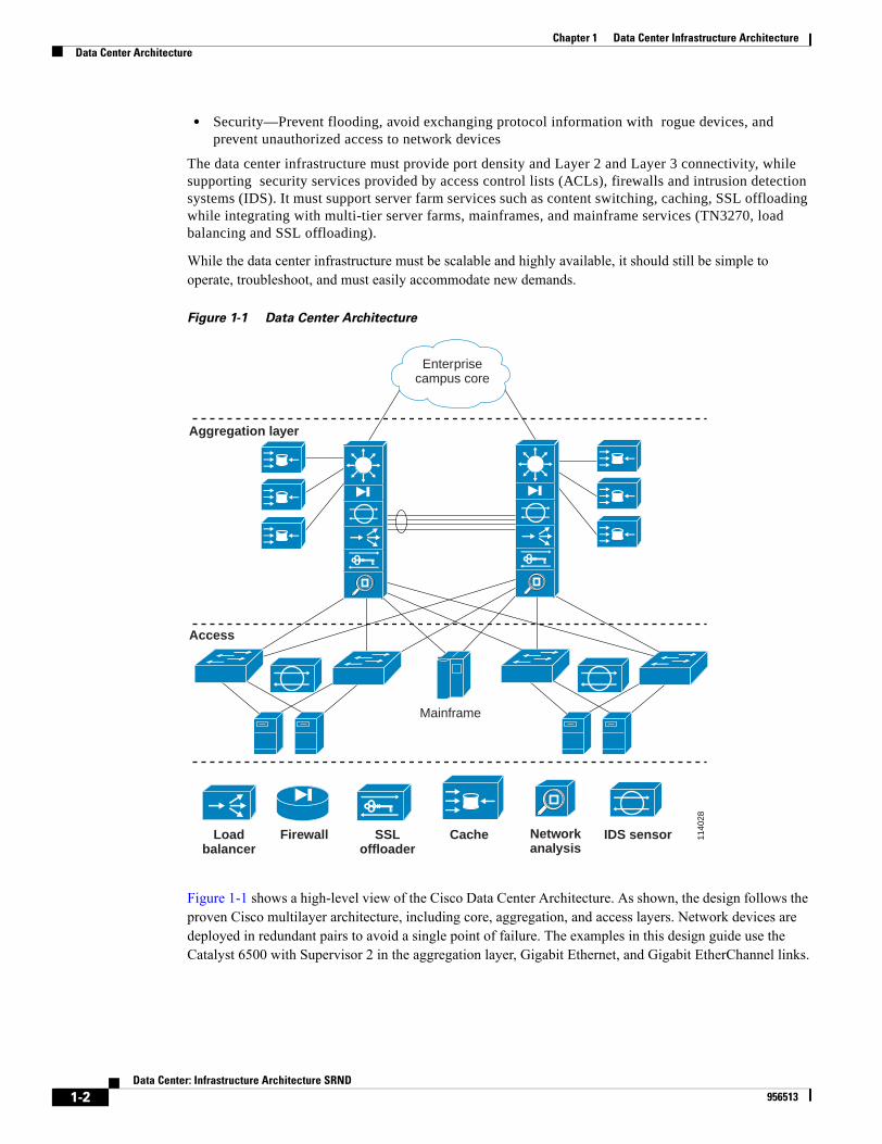
Figure 1-1 Data Center Architecture
Figure 1-1 shows a high-level view of the Cisco Data Center Architecture. As shown, the design follows the proven Cisco multilayer architecture, including core, aggregation, and access layers. Network devices are deployed in redundant pairs to avoid a single point of failure. The examples in this design guide use the Catalyst 6500 with Supervisor 2 in the aggregation layer, Gigabit Ethernet, and Gigabit EtherChannel links.
1140
28
Mainframe
Aggregation layer
Access
Loadbalancer
Firewall SSLoffloader
Cache Networkanalysis
IDS sensor
Enterprisecampus core
1-2Data Center: Infrastructure Architecture SRND
956513

Chapter 1 Data Center Infrastructure ArchitectureHardware and Software Recommendations
Hardware and Software RecommendationsThis section summarizes the recommended hardware and software for implementing a highly available, secure and scalable data center intrastructure. It includes the following topics:
• Aggregation Switches
• Service Appliances and Service Modules
• Access Switches
• Software Recommendations
Aggregation SwitchesThe following are some of the factors to use in choosing the aggregation layer device:
• Forwarding performance
• Density of uplink ports
• Support for 10 Gigabit Ethernet linecards
• Support for 802.1s, 802.1w, Rapid-PVST+
• Support for MPLS-VPNs
• Support for hardware-based NAT
• Support for uRPF in hardware
• QoS characteristics
• Support for load balancing and security services (service modules)
At the aggregation layer, Cisco recommends using Catalyst 6500 family switches because the Catalyst 6500 chassis supports service modules for load balancing and security, including the following:
• Content Service Module (CSM)
• SSL Service Module (SSLSM)
• Firewall Service Module (FWSM)
• Intrusion Detection Service Module (IDSM)
• Network Analysis Module (NAM)
The chassis configuration depends on the specific services you want to support at the aggregation layer, the port density of uplinks and appliances, and the need for supervisor redundancy. Load balancing and security services can also be provided by external service appliances, such as PIX Firewalls; Content Services Switches, Secure Content Accelerators and Content Engines. You also typically attach mainframes to the aggregation switches, especially if you configure each connection to the optical server adapters (OSA) card as a Layer 3 link. In addition, you can use the aggregation switches to attach caches for Reverse Proxy Caching. You can also directly attach servers to the aggregation switches if the port density of the server farm doesn’t require using access switches.
Note The Supervisor 2 (Sup2) and Sup720 are both recommended, but this design guide is intended for use with Sup2. Another design guide will describe the use of Sup720, which provides higher performance and additional functionalities in hardware and is the best choice to build a 10-Gigabit Ethernet data center infrastructure..
1-3Data Center: Infrastructure Architecture SRND
956513
Chapter 1 Data Center Infrastructure ArchitectureHardware and Software Recommendations
The Catalyst 6500 is available in several form factors: • 6503: 3 slots 3 RUs
• 6506: 6 slots 12 RUs
• 7606: 6 slots 7 RUs
• 6509: 9 slots 15 RUs
• 6513: 13 slots, 19 RUs
The 6509 and 6513 are typically deployed in the data center because they provide enough slots for access ports and service modules, such as IDS.The 6500 chassis support a 32 Gbps shared bus, a 256 Gbps fabric (SFM2) and a 720 Gbps fabric (if using Sup720). With a 6509, the Sup2 connects to slot 1 or 2 and the switch fabric (or the Sup720) connects to slot 5 or slot 6. With a 6513, the Sup2 connects to slot 1 or 2, and the switch fabric (or the Sup720) connects to the slot 7 or slot 8. If you use the fabric module (SFM2) with Sup2, each slot in a 6509 receives 16 Gbps of channel attachment. Slots 1-8 in a 6513 receive 8 Gbps and slots 9-13 receive 16 Gbps of channel attachment.If you use Sup720, which has an integrated fabric, each slot in a 6509 receives 40 Gbps of channel attachment. Slots 1-8 in a 6513 receive 20 Gbps, and slots 9-13 receive 40 Gbps of channel attachment.
Catalyst 6509 Hardware Configuration
A typical configuration of a Catalyst 6509 in the aggregation of a data center looks like this:• Sup2 with MSFC2
• FWSM (fabric attached at 8 Gbps)
• CSM
• SSLSM (fabric attached at 8 Gbps)
• IDSM-2 (fabric attached at 8 Gbps)
• WS-X6516A-GBIC or WS-X6516-GBIC – 16 Gigabit Ethernet Fiber Ports – Jumbo (9216 B) – (fabric attached at 8 Gbps) for uplink connectivity with the access switches
• WS-X6516A-GBIC or WS-X6516-GBIC – 16 Gigabit Ethernet Fiber Ports – Jumbo (9216 B) – (fabric attached at 8 Gbps) for uplink connectivity with the access switches
• WS-X6516-GE-TX – 16 10/100/1000 BaseT– Jumbo – (fabric attached at 8 Gbps) for servers and caches
If you use a fabric module, this would plug into slot 5 or 6. Because sup720 has an integrated fabric, this one would also plug into slot 5 or 6.
Catalyst 6513 Hardware Configuration
A typical configuration of a Catalyst 6513 in the aggregation of a data center looks like this:• Sup2 with MSFC2
• FWSM (fabric attached at 8 Gbps)
• CSM
• SSLSM (fabric attached at 8 Gbps)
• IDSM-2 (fabric attached at 8 Gbps)
1-4Data Center: Infrastructure Architecture SRND
956513
Chapter 1 Data Center Infrastructure ArchitectureHardware and Software Recommendations
• NAM-2 (fabric attached at 8 Gbps)
• WS-X6516A-GBIC or WS-X6516-GBIC – 16 Gigabit Ethernet Fiber Ports – Jumbo (9216 B) – (fabric attached at 8 Gbps) for uplink connectivity with the access switches
• WS-X6516A-GBIC or WS-X6516-GBIC – 16 Gigabit Ethernet Fiber Ports – Jumbo (9216 B) – (fabric attached at 8 Gbps) for uplink connectivity with the access switches
• WS-X6516-GE-TX – 16 10/100/1000 BaseT– Jumbo (9216 B) – (fabric attached at 8 Gbps) for servers and caches
If you use a fabric module, this would plug into slot 7 or 8. Because sup720 has an integrated fabric, this one would also plug into slot 7 or 8.
It is also good practice to use the first 8 slots for service modules because these are fabric attached with a single 8 Gbps channel. Use the remaining slots for Ethernet line cards because these might use both fabric channels.
Note When upgrading the system to Sup720 you can keep using the linecards WS-6516-GE-TX, WS-6516-GBIC, WS-6516A-GBIC
Service Appliances
Service appliances are external networking devices that include the following:• Content Service Switch (CSS, CSS11506): 5 RUs, 40 Gbps of aggregate throughput, 2,000
connections per second per module (max 6 modules), 200,000 concurrent connections with 256 MB DRAM.
• CSS11500 SSL decryption module (for the CSS11500 chassis): Performance numbers per module: 1,000 new transactions per second, 20,000 concurrent sessions, 250 Mbps of throughput.
• PIX Firewalls (PIX 535): 3 RU, 1.7 Gpbs of throughput, 500,000 concurrent connections
• IDS sensors (IDS 4250XL): 1 RU, 1 Gbps (with the XL card)
• Cisco Secure Content Accelerator 2: 1 RU, 800 new transactions per second, 20,000 concurrent sessions, 70 Mbps of bulk transfer
The number of ports that these appliances require depends entirely on how many appliances you use and how you configure the Layer 2 and Layer 3 connectivity between the appliances and the infrastructure.
Service Modules
Security and load balancing services in the data center can be provided either with appliances or with Catalyst 6500 linecards. The choice between the two family of devices is driven by considerations of performance, rack space utilization, cabling and of course features that are specific to each of the devices.
Service modules are cards that you plug into the Catalyst 6500 to provide firewalling, intrusion detection, content switching, and SSL offloading. Service modules communicate with the network through the Catalyst backplane and can be inserted without the need for additional power or network cables.
Service modules provide better rack space utilisation, simplified cabling, better integration between the modules and higher performance than typical appliances. When using service modules, certain configurations that optimize the convergence time and the reliability of the network are automatic. For
1-5Data Center: Infrastructure Architecture SRND
956513
Chapter 1 Data Center Infrastructure ArchitectureHardware and Software Recommendations
example, when you use an external appliance, you need to manually configure portfast or trunkfast on the switch port that connects to the appliance. This configuration is automatic when you use a service module.
As an example of rack space utilization consider that a PIX 535 firewall takes 3 Rack Units (RUs), while a Firewall Services Module (FWSM) takes one slot in a Catalyst switch, which means that a FWSM inside a Catalyst 6513 takes (19 RU / 13 slots) = 1.4 RUs.
Another advantage of using service modules as opposed to external appliances is that service modules are VLAN aware, which makes consolidation and virtualization of the infrastructure easier.
Each service module provides a different functionality and takes one slot out of the Catalyst 6500. Examples of these modules include the following:
• CSM: 165,000 connections per second, 1,000,000 concurrent connections, 4 Gbps of throughput.
• FWSM: 8 Gpbs fabric attached . Performance numbers: 100,000 cps, 5.5Gbps of throughput, 1,000,000 cc.
• SSLSM: 8 Gbps fabric attached. Performance numbers: 3000 new transactions per second, 60,000 concurrent connections, 300 Mbps of throughput.
• IDSM-2: 8 Gbps fabric attached. Performance: 600 Mbps
Access Switches
This section describes how to select access switches for your data center intrastructure design and describes some of the Cisco Catalyst products that are particularly useful. It includes the following topics:
• Selecting Access Switches
• Catalyst 6500
• Catalyst 4500
• Catalyst 3750
Selecting Access Switches
The following are some of the factors to consider when choosing access layer switches:
• Forwarding performance
• Oversubscription rates
• Support for 10/100/1000 linecards
• Support for 10 Gigabit Ethernet (for uplink connectivity)
• Support for Jumbo Frames
• Support for 802.1s, 802.1w, Rapid-PVST+
• Support for stateful redundancy with dual supervisors
• Support for VLAN ACLs (used in conjunction with IDS)
• Support for Layer 2 security features such as port security and ARP inspection
• Support for private VLANs
• Support for SPAN and Remote SPAN (used in conjunction with IDS)
• Support for QoS
1-6Data Center: Infrastructure Architecture SRND
956513
Chapter 1 Data Center Infrastructure ArchitectureHardware and Software Recommendations
• Modularity
• Rack space and cabling efficiency
• Power redundancy
Cost often requires choosing less expensive server platforms that only support one NIC card. To provide availability for these single-homed servers you need to use dual supervisors in the access switch. For dual supervisor redundancy to be effective you need stateful failover at least to Layer 2.
When choosing linecards or other products to use at the access layer, consider how much oversubscription a given application tolerates. When choosing linecards, you should also consider support for Jumbo frames and the maximum queue size.
Modular switches support both oversubscribed and non-oversubscribed linecards. Typically, you use oversubscribed linecards as access ports for server attachment and non-oversubscribed linecards for uplink ports or channels between switches. You might need to use non-oversubscribed linecards for the server ports as well, depending on the amount of traffic that you expect a server to generate.
Although various platforms can be used as access switches, this design guide uses the Catalyst 6506. Using service modules in an access switch can improve rack space utilization and reduce cabling if you deploy load balancing and security at the access layer. From the data center design perspective, the access layer (front-end switches) must support 802.1s/1w and Rapid PVST+ to take advantage of rapid convergence.The 10/100/1000 technology allows incremental adoption of Gigabit Ethernet in the server farm thanks to the compatibility between FastEthernet NIC cards and 10/100/1000 switch linecards. 10 Gigabit Ethernet is becoming the preferred technology for the data center uplinks within the data center and between the data center and the core.Cabling between the servers and the switch can be either fiber or copper. Gigabit over copper can run on the existing Cat 5 cabling used for Fast Ethernet (ANSI/TIA/EIA 568-A, ISO/IEC 11801-1995). Cat 5 cabling was designed for the use of 2 cable pairs, but Gigabit Ethernet uses 4 pairs. Existing Cat 5 wiring infrastructure must be tested to ensure it can effectively support Gigabit rates. New installations of Gigabit Ethernet over copper should use at least Cat 5e cabling or, better, Cat 6.
Note For more information on the cabling requirements of 1000BaseT refer to the document “Gigabit Ethernet Over Copper Cabling” published on www.gigabitsolution.com
Catalyst 6500
The Catalyst 6500 supports all the technologies and features required for implementing a highly available, secure, and scalable data center intrastructure. The platform used in this design guide for the access switches is the 6506 because it provides enough slots for access ports and service modules together with efficient rack space utilisation.
A typical configuration for the Catalyst 6500 in the access layer is as follows:• Single or dual supervisors (two supervisors are recommended for single-homed servers)
• IDSM-2
• Access ports for the servers 10/100/1000 linecards: WS-6516-GE-TX – Jumbo (9216 B), fabric attached at 8 Gbps
• Gigabit linecard for uplink connectivity: WS-6516-GBIC or WS-6516A-GBIC – Jumbo (9216 B), fabric attached at 8 Gbps
1-7Data Center: Infrastructure Architecture SRND
956513
Chapter 1 Data Center Infrastructure ArchitectureHardware and Software Recommendations
Note It is possible to attach 1000BaseT GBIC adapters to Optical Gigabit linecards by using the WS-G5483 GBIC
If the Catalyst 6506 is upgraded to Sup720, Sup720 will be plugged into slot 5 or slot 6. For this reason when using Sup2 it is practical to keep either slot empty for a possible upgrade or to insert a fabric module. When upgrading the system to Sup720 you can keep using the linecards WS-6516-GE-TX, WS-6516-GBIC, WS-6516A-GBIC
Catalyst 4500
The Catalyst 4500, which can also be used as an access switch in the data center is a modular switch available with the following chassis types:
• 4503: 3 slots, 7 RUs
• 4506: 6 slots, 10 RUs
• 4507R: 7 slots, 11 RUs (slot 1 and 2 are reserved for the supervisors and do not support linecards)
Only the 4507R supports dual supervisors. A typical configuration with supervisor redundancy and layer 2 access would be as follows:
• Dual Sup2-plus (mainly layer 2 + static routing and RIP) or dual supervisor IV (for layer 3 routing protocols support with hardware CEF)
• Gigabit copper attachment for servers, which can use one of the following:
• WS-4306-GB with copper GBICs (WS-G5483)
• 24-port 10/100/1000 WS-X4424-GB-RJ45
• 12-port 1000BaseT linecard WS-X4412-2GB-T
• Gigabit fiber attachment for servers, which can use a WS-X4418-GB (this doesn’t support copper GBICs)
• Gigabit linecard for uplink connectivity: WS-4306-GB – Jumbo (9198 B)
Note Jumbo frames are only supported on non-oversubscribed ports.
When internal redundancy is not required, you don’t need to use a 4507 chassis and you can use a Supervisor 3 for Layer 3 routing protocol support and CEF switching in hardware.
Catalyst 3750
The Catalyst 3750 is a stackable switch that supports Gigabit Ethernet, such as the 24-port 3750G-24TS with 10/100/1000 ports and 4 SFP for uplink connectivity. Several 3750s can be clustered together to logically form a single switch. In this case, you could use 10/100/1000 switches (3750-24T) clustered with an SFP switch (3750G-12S) for EtherChannel uplinks.
Software Recommendations
Because of continous improvements in the features that are supported on the access switch platforms
1-8Data Center: Infrastructure Architecture SRND
956513
Chapter 1 Data Center Infrastructure ArchitectureData Center Multi-Layer Design
described in this design document, it isn't possible to give a recommendation on the software release you should deploy in your data center.
The choice of the software release depends on the hardware that the switch needs to support and on the stability of a given version of code. In a data center design, you should use a release of code that has been released for a long time, is available with several re-builds, and where the newer builds contain only bug fixes.
When using Catalyst family products, you must choose between using the Supervisor IOS operating system or the Catalyst IOS operating systems. These two operating systems have some important differences in the CLI, the features supported, and the hardware supported.
This design document uses supervisor IOS on the Catalyst 6500 aggregation switches because it supports Distributed Forwarding Cards, and because it was the first operating system to support the Catalyst service modules. Also, it is simpler to use a single standardized image and a single operating system on all the data center devices
The following summarizes the features introduced with different releases of the software:• 12.1(8a)E—Support for Sup2 and CSM
• 12.1(13)E—Support for Rapid PVST+ and for FWSM, NAM2 with Sup2, and SSLSM with Sup2
• 12.1(14)E—Support for IDSM-2 with Sup2
• 12.1(19)E—Support for some of the 6500 linecards typically used in data centers and SSHv2
This design guide is based on testing with Release 12.1(19)Ea1.
Data Center Multi-Layer DesignThis section describes the design of the different layers of the data center infrastructure. It includes the following topics:
• Core Layer
• Aggregation Layer
• Access Layer
• Service Switches
• Server Availability
Core Layer
The core layer in an enterprise network provides connectivity among the campus buildings, the private WAN network, the Internet edge network and the data center network. The main goal of the core layer is to switch traffic at very high speed between the modules of the enterprise network. The configuration of the core devices is typically kept to a minimum, which means pure routing and switching. Enabling additional functions might bring down the performance of the core devices.
There are several possible types of core networks. In previous designs, the core layer used a pure Layer 2 design for performance reasons. However, with the availability of Layer 3 switching, a Layer 3 core is as fast as a Layer 2 core. If well designed, a Layer 3 core can be more efficient in terms of convergence time and can be more scalable.
1-9Data Center: Infrastructure Architecture SRND
956513
Chapter 1 Data Center Infrastructure ArchitectureData Center Multi-Layer Design
For an analysis of the different types of core, refer to the white paper available on www.cisco.com: “Designing High-Performance Campus Intranets with Multilayer Switching” by Geoff Haviland.
The data center described in this design guide connects to the core using Layer 3 links. The data center network is summarized and the core injects a default into the data center network. Some specific applications require injecting host routes (/32) into the core.
Aggregation and Access Layer
The access layer provides port density to the server farm, while the aggregation layer collects traffic from the access layer and connects the data center to the core. The aggregation layer is also the preferred attachment point for mainframes and the attachment point for caches used in Reverse Proxy Cache mode.
Security and application service devices (such as load balancing devices, SSL offloading devices, firewalls and IDS devices) are deployed either at the aggregation or access layer. Service devices deployed at the aggregation layer are shared among all the servers, while services devices deployed at the access layer provide benefit only to the servers that are directly attached to the specific access switch.
The design of the access layer varies depending on whether you use Layer 2 or Layer 3 access. Layer 2 access is more efficient for sharing aggregation layer services among the servers. For example, to deploy a firewall that is used by all the servers in the data center, deploy it at the aggregation layer. The easiest implementation is with the firewall Layer 2 adjacent to the servers because the firewall should see both client-to-server and server-to-client traffic.
Security and application services are provided by deploying external appliances or service modules. The Cisco preferred architecture for large-scale server farms uses service modules for improved integration and consolidation. A single service module can often replace multiple external appliances with a single linecard.
Figure 1-1 shows the aggregation switches with firewalling, IDS, load balancing, SSL offloading and NAM in the same switch. This configuration needs to be customized for specific network requirements and is not the specific focus of this document. For information about designing data centers with service modules, refer to .
Service Switches
The architecture shown in Figure 1-1 is characterized by high density in service modules on each aggregation switch, which limits the number of ports available for uplink connectivity. It is also possible that the code versions required by the service modules may not match the software version already used on the aggregation switches in the data center environment.
Figure 1-2 illustrates the use of service switches in a data center. Service switches are Catalyst 6500 populated with service modules and dual-attached to the aggregation switches. When used with service modules, they allow higher port density and separate the code requirements of the service modules from those of the aggregation switches.
1-10Data Center: Infrastructure Architecture SRND
956513
Chapter 1 Data Center Infrastructure ArchitectureData Center Multi-Layer Design
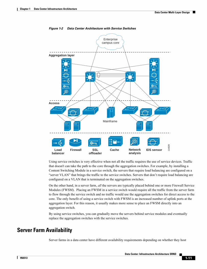
Figure 1-2 Data Center Architecture with Service Switches
Using service switches is very effective when not all the traffic requires the use of service devices. Traffic that doesn't can take the path to the core through the aggregation switches. For example, by installing a Content Switching Module in a service switch, the servers that require load balancing are configured on a “server VLAN” that brings the traffic to the service switches. Servers that don’t require load balancing are configured on a VLAN that is terminated on the aggregation switches.
On the other hand, in a server farm, all the servers are typically placed behind one or more Firewall Service Modules (FWSM). Placing an FWSM in a service switch would require all the traffic from the server farm to flow through the service switch and no traffic would use the aggregation switches for direct access to the core. The only benefit of using a service switch with FWSM is an increased number of uplink ports at the aggregation layer. For this reason, it usually makes more sense to place an FWSM directly into an aggregation switch.
By using service switches, you can gradually move the servers behind service modules and eventually replace the aggregation switches with the service switches.
Server Farm Availability
Server farms in a data center have different availability requirements depending on whether they host
1140
29
Mainframe
Aggregation layer
Access
Loadbalancer
Firewall SSLoffloader
Cache Networkanalysis
IDS sensor
Enterprisecampus core
1-11Data Center: Infrastructure Architecture SRND
956513

Chapter 1 Data Center Infrastructure ArchitectureData Center Multi-Layer Design
business-critical applications or applications with less stringent availability requirements, such as development applications. You can meet availability requirements by leveraging specific software technologies and network technologies, including the following:
Applications can be load-balanced either with a network device or with clustering softwareServers can be multi-homed with multiple NIC cardsAccess switches can provide maximum availability if deployed with dual supervisors
Load-Balanced Servers
Load-balanced servers are located behind a load balancer, such as CSM. Load-balanced server farms typically include the following kinds of servers:
• Web and application servers
• DNS servers
• LDAP servers
• RADIUS servers
• TN3270 servers
• Streaming servers
Note The document at the following URL outlines some of the popular applications of load balancing: http://www.cisco.com/warp/public/cc/pd/cxsr/400/prodlit/sfarm_an.htm
Load-balanced server farms benefit from load distribution, application monitoring, and application-layer services, such as session persistence. On the other hand, while the 4 Gbps throughput of a CSM is sufficient in most client-to-server environments, it could be a bottleneck for bulk server-to-server data transfers in large-scale server farms.
When the server farm is located behind a load balancer, you may need to choose one of the following options to optimize server-to-server traffic:
• Direct Server Return
• Performing client NAT on the load balancer
• Policy Based Routing
The recommendations in this document apply to network design with a CSM and should be deployed before installing the CSM.
A key difference between load-balanced servers and non-load balanced servers is the placement of the default gateway. Non-load balanced servers typically have their gateway configured as a Hot Standby Routing Protocol (HSRP) address on the router inside the Catalyst 6500 switch or on the firewall device. Load-balanced servers may use the IP address of the load balancing device as their default gateway.
Levels of Server Availability
Each enterprise categorizes its server farms based on how critical they are to the operation of the business. Servers that are used in production and handle sales transaction are often dual-homed and configured for “switch fault tolerance.” This means the servers are attached with two NIC cards to separate switches, as shown in Figure 1-1. This allows performing maintenance on one access switch without affecting access to
1-12Data Center: Infrastructure Architecture SRND
956513

Chapter 1 Data Center Infrastructure ArchitectureData Center Multi-Layer Design
the server.
Other servers, such as those used for developing applications, may become inaccessible without immediately affecting the business. You can categorize the level of availability required for different servers as follows:
• Servers configured with multiple NIC cards each attached to a different access switch (switch fault tolerance) provide the maximum possible availability. This option is typically reserved to servers hosting business critical applications.
• Development servers could also use two NICs that connect to a single access switch which has two supervisors. This configuration of the NIC cards goes under the name of “adapter fault tolerance”. The two NICs should be attached to different linecards.
• Development servers that are less critical to the business can use one NIC connected to a single access switch (which has two supervisors)
• Development servers that are even less critical can use one NIC connected to a single access switch which has a single supervisor
The use of access switches with two supervisors provides availability for servers that are attached to a single access switch. The presence of two supervisors makes it possible to perform software upgrades on one supervisor with minimal disruption of the access to the server farm.
Adapter fault tolerance means that the server is attached with each NIC card to the same switch but each NIC card is connected to a different linecard in the access switch.Switch fault tolerance and adapter fault tolerance are described in Chapter 3, “HA Connectivity for Servers and Mainframes: NIC Teaming and OSA/OSPF Design.”
Multi-Tier Server Farms
Today, most web-based applications are built as multi-tier applications. The multi-tier model uses software running as separate processes on the same machine, using interprocess communication, or on different machines with communications over the network. Typically, the following three tiers are used:
• Web-server tier
• Application tier
• Data base tier
Multi-tier server farms built with processes running on separate machines can provide improved resiliency and security. Resiliency is improved because a server can be taken out of service while the same function is still provided by another server belonging to the same application tier. Security is improved because an attacker can compromise a web server without gaining access to the application or to the database.
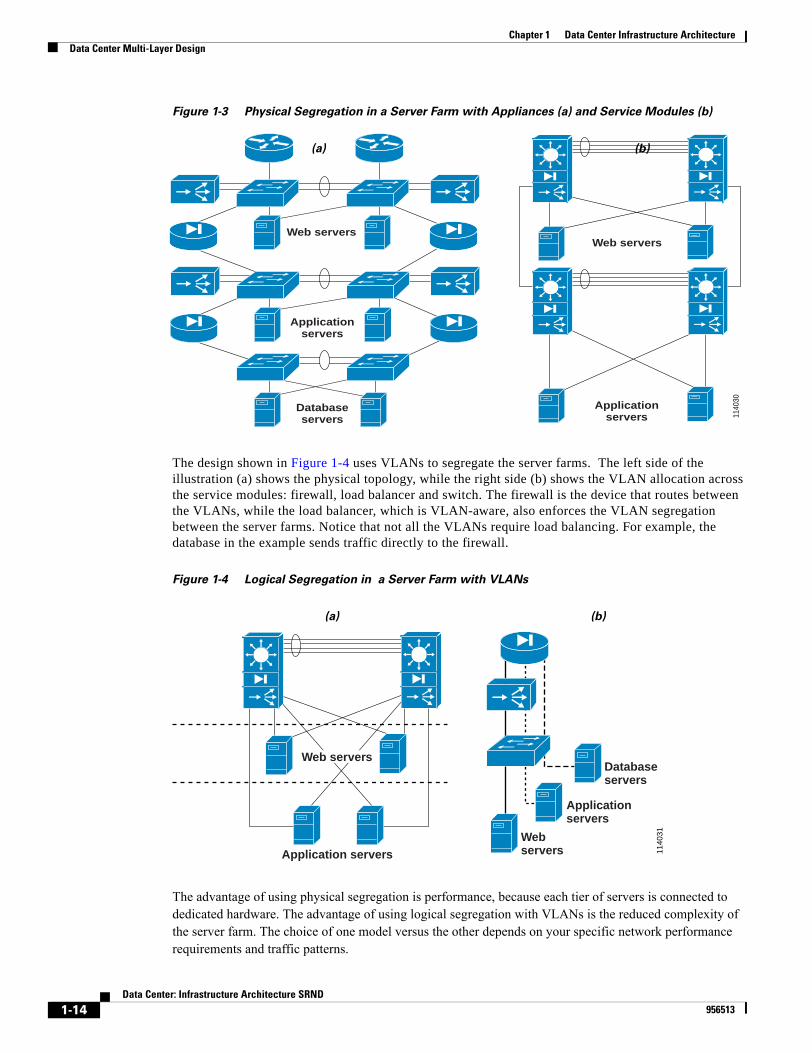
Resiliency is achieved by load balancing the network traffic between the tiers, and security is achieved by placing firewalls between the tiers. You can achieve segregation between the tiers by deploying a separate infrastructure made of aggregation and access switches or by using VLANs.Figure 1-3 shows the design of multi-tier server farms with physical segregation between the server farm tiers. Side (a) of the figure shows the design with external appliances, while side (b) shows the design with service modules
1-13Data Center: Infrastructure Architecture SRND
956513
Chapter 1 Data Center Infrastructure ArchitectureData Center Multi-Layer Design
Figure 1-3 Physical Segregation in a Server Farm with Appliances (a) and Service Modules (b)
The design shown in Figure 1-4 uses VLANs to segregate the server farms. The left side of the illustration (a) shows the physical topology, while the right side (b) shows the VLAN allocation across the service modules: firewall, load balancer and switch. The firewall is the device that routes between the VLANs, while the load balancer, which is VLAN-aware, also enforces the VLAN segregation between the server farms. Notice that not all the VLANs require load balancing. For example, the database in the example sends traffic directly to the firewall.
Figure 1-4 Logical Segregation in a Server Farm with VLANs
The advantage of using physical segregation is performance, because each tier of servers is connected to dedicated hardware. The advantage of using logical segregation with VLANs is the reduced complexity of the server farm. The choice of one model versus the other depends on your specific network performance requirements and traffic patterns.
1140
30
Web servers
Applicationservers
Web servers
Applicationservers
Databaseservers
(a) (b)
1140
31
Application servers
Web servers
Webservers
Applicationservers
Databaseservers
(a) (b)
1-14Data Center: Infrastructure Architecture SRND
956513
Chapter 1 Data Center Infrastructure ArchitectureData Center Protocols and Features
Data Center Protocols and FeaturesThis section provides background information about protocols and features that are helpful when designing a data center network for high availability, security and scalability. It includes the following topics:
• Layer 2 Protocols
• Layer 3 Protocols
• Security in the Data Center
Layer 2 Protocols
Data centers are characterized by a wide variety of server hardware and software. Applications may run on various kinds of server hardware, running different operating systems. These applications may be developed on different platforms such as IBM Websphere, BEA Weblogic, Microsoft .NET, Oracle 9i or they may be commercial applications developed by companies like SAP, Siebel, or Oracle. Most server farms are accessible using a routed IP address, but some use non-routable VLANs.
All these varying requirements determine the traffic path that client-to-server and server-to-server traffic takes in the data center.These factors also determine how racks are built because server farms of the same kind are often mounted in the same rack based on the server hardware type and are connected to an access switch in the same rack. These requirements also decide how many VLANs are present in a server farm because servers that belong to the same application often share the same VLAN.
The access layer in the data center is typically built at Layer 2, which allows better sharing of service devices across multiple servers, and allows the use of Layer 2 clustering, which requires the servers to be Layer 2 adjacent. With Layer 2 access, the default gateway for the servers is configured at the aggregation layer. Between the aggregation and access layers there is a physical loop in the topology that ensures a redundant Layer 2 path in case one of the links from the access to the aggregation fails.
Spanning-tree protocol (STP) ensures a logically loop-free topology over a physical topology with loops. Historically, STP (IEEE 802.1d and its Cisco equivalent PVST+) has often been dismissed because of slow convergence and frequent failures that are typically caused by misconfigurations. However, with the introduction of IEEE 802.1w, spanning-tree is very different from the original implementation. For example, with IEEE 802.1w, BPDUs are not relayed, and each switch generates BPDUs after an interval determined by the “hello time.” Also, this protocol is able to actively confirm that a port can safely transition to forwarding without relying on any timer configuration. There is now a real feedback mechanism that takes place between IEEE 802.1w compliant bridges.
We currently recommend using Rapid Per VLAN Spanning Tree Plus (PVST+), which is a combination of 802.1w and PVST+. For higher scalability, you can use 802.1s/1w, also called multi-instance spanning-tree (MST). You get higher scalability with 802.1s because you limit the number of spanning-tree instances, but it is less flexible than PVST+ if you use bridging appliances. The use of 802.1w in both Rapid PVST+ and MST provides faster convergence than traditional STP. We also recommend other Cisco enhancements to STP, such as LoopGuard and Unidirectional Link Detection (UDLD), in both Rapid PVST+ and MST environments.
We recommend Rapid PVST+ for its flexibility and speed of convergence. Rapid PVST+ supersedes BackboneFast and UplinkFast making the configuration easier to deploy than regular PVST+. Rapid PVST+ also allows extremely easy migration from PVST+.
Interoperability with IEEE 802.1d switches that do not support Rapid PVST+ is ensured by building the
1-15Data Center: Infrastructure Architecture SRND
956513
Chapter 1 Data Center Infrastructure ArchitectureData Center Protocols and Features
“Common Spanning-Tree” (CST) by using VLAN 1. Cisco switches build a CST with IEEE 802.1d switches, and the BPDUs for all the VLANs other than VLAN 1 are tunneled through the 802.1d region.
Cisco data centers feature a fully-switched topology, where no hub is present, and all links are full-duplex. This delivers great performance benefits as long as flooding is not present. Flooding should only be used during topology changes to allow fast convergence of the Layer 2 network. Technologies that are based on flooding introduce performance degradation besides being a security concern. This design guide provides information on how to reduce the likelihood of flooding. Some technologies rely on flooding, but you should use the equivalent unicast-based options that are often provided.
Flooding can also be the result of a security attack and that is why port security should be configured on the access ports together with the use of other well understood technologies, such as PortFast. You complete the Layer 2 configuration with the following configuration steps:
Step 1 Proper assignment of root and secondary root switches
Step 2 Configuring rootguard on the appropriate links
Step 3 Configuring BPDU guard on the access ports connected to the servers.
By using these technologies you control the Layer 2 topology from accidental or malicious changes that could alter the normal functioning of the network.
The Layer 2 configuration needs to keep into account the presence of dual-attached servers. Dual attached servers are used for redundancy and increased throughput. The configurations in this design guide ensure compatibility with dual-attached servers.
Layer 3 Protocols
The aggregation layer typically provides Layer 3 connectivity from the data center to the core. Depending on the requirements and the design, the boundary between Layer 2 and Layer 3 at the aggregation layer can be the Multilayer Switching Feature Card (MSFC), which is the router card inside the Catalyst supervisor, the firewalls, or the content switching devices. You can achieve routing either with static routes or with routing protocols such as EIGRP and OSPF. This design guide covers routing using EIGRP and OSPF.
Network devices, such as content switches and firewalls, often have routing capabilities. Besides supporting the configuration of static routes, they often support RIP and sometimes even OSPF. Having routing capabilities facilitates the task of the network design but you should be careful not to misuse this functionality. The routing support that a content switch or a firewall provides is not the same as the support that a router has, simply because the main function of a content switching product or of a firewall is not routing. Consequently, you might find that some of the options that allow you to control how the topology converges (for example, configuration of priorities) are not available. Moreover, the routing table of these devices may not accommodate as many routes as a dedicated router.
The routing capabilities of the MSFC, when used in conjunction with the Catalyst supervisor, provide traffic switching at wire speed in an ASIC. Load balancing between equal-cost routes is also done in hardware These capabilities are not available in a content switch or a firewall.
We recommend using static routing between the firewalls and the MSFC for faster convergence time in case of firewall failures, and dynamic routing between the MSFC and the core routers. You can also use dynamic routing between the firewalls and the MSFC, but this is subject to slower convergence in case of firewall
1-16Data Center: Infrastructure Architecture SRND
956513
Chapter 1 Data Center Infrastructure ArchitectureData Center Protocols and Features
failures. Delays are caused by the process of neighbor establishment, data base exchange, running the SPF algorithm and installing the Layer 3 forwarding table in the network processors.
Whenever dynamic routing is used, routing protocols with MD5 authentication should be used to prevent the aggregation routers from becoming neighbors with rogue devices. We also recommend tuning the OSPF timers to reduce the convergence time in case of failures of Layer 3 links, routers, firewalls, or LPARs (in a mainframe).
Servers use static routing to respond to client requests. The server configuration typically contains a single default route pointing to a router, a firewall, or a load balancer. The most appropriate device to use as the default gateway for servers depends on the security and performance requirements of the server farm. Of course, the highest performance is delivered by the MSFC.
You should configure servers with a default gateway with an address that is made highly available through the use of gateway redundancy protocols such as HSRP, Virtual Router Redundancy Protocol (VRRP), or the Gateway Load Balancing Protocol (GLBP). You can tune the gateway redundancy protocols for convergence in less than one second, which makes router failures almost unnoticeable to the server farm.
Note The software release used to develop this design guide only supports HSRP.
Mainframes connect to the infrastructure using one or more OSA cards. If the mainframe uses Enterprise System Connections (ESCON), it can be connected to a router with a Channel Interface Processor (CIP/CPA). The CIP connects to the mainframes at the channel level. By using an ESCON director, multiple hosts can share the same CIP router. Figure 1-1 shows the attachment for a mainframe with an OSA card.
The transport protocol for mainframe applications is IP, for the purpose of this design guide. You can provide clients direct access to the mainframe or you can build a multi-tiered environment so clients can use browsers to run mainframe applications. The network not only provides port density and Layer 3 services, but can also provide the TN3270 service from a CIP/CPA card. The TN3270 can also be part of a multi-tiered architecture, where the end client sends HTTP requests to web servers, which, in turn, communicate with the TN3270 server. You must build the infrastructure to accommodate these requirements as well.
You can configure mainframes with static routing just like other servers, and they also support OSPF routing. Unlike most servers, mainframes have several internal instances of Logical Partitions (LPARs) and/or Virtual machines (VMs), each of which contains a separate TCP/IP stack. OSPF routing allows the traffic to gain access to these partitions and/or VMs using a single or multiple OSA cards.
You can use gateway redundancy protocols in conjunction with static routing when traffic is sent from a firewall to a router or between routers. When the gateway redundancy protocol is tuned for fast convergence and static routing is used, recovery from router failures is very quick. When deploying gateway redundancy protocols, we recommend enabling authentication to avoid negotiation with unauthorized devices.
Routers and firewalls can provide protection against attacks based on source IP spoofing, by means of unicast Reverse Path Forwarding (uRPF). The uRPF feature checks the source IP address of each packet received against the routing table. If the source IP is not appropriate for the interface on which it is received, the packet is dropped. We recommend that uRPF be enabled on the Firewall module in the data center architecture described in this design guide.
1-17Data Center: Infrastructure Architecture SRND
956513

Chapter 1 Data Center Infrastructure ArchitectureScaling Bandwidth
Security in the Data Center
Describing the details of security in the data center is beyond the scope of this document, but it is important to be aware of it when building the infrastructure. Security in the data center is the result of Layer 2 and Layer 3 configurations (such as routing authentication, uRPF, and so forth) and the use of security technologies such as SSL, IDS, firewalls, and monitoring technologies such as network analysis products.
Firewalls provide Layer 4 security services such as Initial Sequence Number randomization, TCP intercept, protection against fragment attacks and opening of specific Layer 4 ports for certain applications (fixups). An SSL offloading device can help provide data confidentiality and non-repudiation, while IDS devices capture malicious activities and block traffic generated by infected servers on the access switches. Network analysis devices measure network performance, port utilization, application response time, QoS, and other network activity.
Note Strictly speaking, network analysis devices are not security devices. They are network management devices, but by observing network and application traffic it is sometimes possible to detect malicious activity.
Some of the functions provided by the network, such as SYN COOKIEs and SSL, may be available on server operating systems. However, implementing these functionalities on the network greatly simplifies the management of the server farm because it reduces the number of configuration points for each technology. Instead of configuring SSL on hundreds of servers you just configure SSL on a pair of SSL offloading devices.
Firewalls and SSL devices see the session between client and server and directly communicate with both entities. Other security products such as IDS devices or NAM devices, only see a replica of the traffic without being on the main traffic path. For these products to be effective, the switching platforms need to support technologies such as VACL capture and Remote SPAN in hardware.
Scaling BandwidthThe amount of bandwidth required in the data center depends on several factors, including the application type, the number of servers present in the data center, the type of servers, the storage technology. The need for network bandwidth in the data center is increased because of the large amount of data that is stored in a data center and the need to quickly move this data between servers. The technologies that address these needs include:
• EtherChannels—Either between servers and switches or between switches
• CEF load balancing—Load balancing on equal cost layer 3 routes
• GigabitEthernet attached servers—Upgrading to Gigabit attached servers is made simpler by the adoption of the 10/100/1000 technology
• 10 GigabitEthernet—10 GigabitEthernet is being adopted as an uplink technology in the data center
• Fabric switching—Fabric technology in data center switches helps improve throughput in the communication between linecards inside a chassis, which is particularly useful when using service modules in a Catalyst switch.
You can increase the bandwdith available to servers by using multiple server NIC cards either in load balancing mode or in link-aggregation (EtherChannel) mode.
1-18Data Center: Infrastructure Architecture SRND
956513
Chapter 1 Data Center Infrastructure ArchitectureNetwork Management
EtherChannel allows increasing the aggregate bandwidth at Layer 2 by distributing traffic on multiple links based on a hash of the Layer 2, Layer 3 and Layer 4 information in the frames.
EtherChannels are very effective in distributing aggregate traffic on multiple physical links, but they don’t provide the full combined bandwidth of the aggregate links to a single flow because the hashing assigns the flow to a single physical link. For this reason, GigabitEthernet NIC cards are becoming the preferred technology for FastEtherChannels. This is a dominant trend because of the reduced cost of copper Gigabit NICs compared to fiber NICs. For a similar reason, 10 GigabitEthernet is becoming the preferred technology for enabling GigabitEtherchannels for data center uplinks.
At the aggregation layer, where service modules are deployed, the traffic between the service modules travels on the bus of the Catalyst 6500 several times. This reduces the bandwidth available for server-to-server traffic The use of the fabric optimizes the communication between fabric-connected linecards and fabric-attached service modules. With Sup720 the fabric is part of the supervisor itself. With the sup 2, the fabric is available as a separate module.
Note Not all service modules are fabric attached. Proper design should ensure the best utilization of the service modules within the Catalyst 6500 chassis.
The maximum performance that a Catalyst switch can deliver is achieved by placing the servers Layer 2 adjacent to the MSFC interface. Placing service modules, such as firewalls or load balancers, in the path delivers high performance load balancing and security services, but this design doesn’t provide the maximum throughput that the Catalyst fabric can provide.
As a result, servers that do not require load balancing should not be placed behind a load balancer, and if they require high throughput transfers across different VLANs you might want to place them adjacent to an MSFC interface. The FWSM provides ~5.5 Gbps of throughput and the CSM provides ~4Gbps of throughput.
Network ManagementThe management of every network device in the data center needs to be secured to avoid unauthorized access. This basic concept is applicable in general but it is even more important in this design because the firewall device is deployed as a module inside the Catalyst 6500 chassis. You need to ensure that nobody changes the configuration of the switch to bypass the firewall.
You can promote secure management access through using Access Control Lists (ACL), Authentication Authorization and Accounting (AAA), and Secure Shell (SSH). We recommend using a Catalyst IOS software release greater than 12.1(19)E1a to take advantage of SSHv2.
You should deploy syslog at an informational level, and when available the syslogs should be sent to a server rather than stored on the switch or router buffer: When a reload occurs, syslogs stored on the buffer are lost, which makes their use in troubleshooting difficult. Disable console logging during normal operations.
Configuration management is another important aspect of network management in the data center. Proper management of configuration changes can significantly improve data center availability. By periodically retrieving and saving configurations and by auditing the history of configuration changes you can understand the cause of failures and ensure that managed devices comply with the standard configurations.
Software management is critical for achieving maximum data center availability. Before upgrading the
1-19Data Center: Infrastructure Architecture SRND
956513
Chapter 1Network Management
software to a new release you should know about the compatibility of the installed hardware image. Network management tools can retrieve the information from Cisco Connection Online and compare it with the hardware present in your data center. Only after you are sure that the requirements are met, should you distribute the image to all the devices. You can use software management tools to retrieve the bug information associated with device images and compare it to the bug information for the installed hardware to identify the relevant bugs.
You can use Cisco Works 2000 Resource Manager Essentials (RME) to perform configuration management, software image management, and inventory management of the Cisco data center devices. This requires configuring the data center devices with the correct SNMP community strings. You can also use RME as the syslog server. We recommend RME version 3.5 with Incremental Device Update v5.0 (for Sup720, FWSM, and NAM support) and v6.0 (for CSM support).
1-20Data Center: Infrastructure Architecture SRND
956513
Data C956513
C H A P T E R 2
Data Center Infrastructure DesignThis chapter describes design issues, including routing between the data center and the core, switching within the server farm, and establishing mainframe connectivity. It includes the following sections:
• Routing Between the Data Center and the Core, page 2-1
• Switching Architecture for the Server Farm, page 2-9
Routing Between the Data Center and the CoreThis section describes the issues you should address when designing the routing infrastructure between the data center and core. It includes the following topics:
• Layer 3 Data Center Design
• Using OSPF
• Using EIGRP
• Designing Layer 3 Security
Layer 3 Data Center DesignThis design guide addresses designs with routing protocols with special attention to EIGRP and OSPF. Key characteristics of these designs include the following:
• Use Layer 3 links between routing devices, when possible
• Summarization occurs from the data center to the core
• Inside the data center, passive all VLANs except one used to keep a Layer 3 escape route with the neighboring MSFC
• Passive VLANs where you do not need to establish neighbor relationship between routers
• As much as possible, provide the default gateway at the MSFC via HSRP
• Alternatively the default gateway is provided by content switches or firewalls
The routing between the data center and the core typically is performed on the MSFC.
The Layer 3 portion of the data center design changes slightly depending on it is an Internet data center or an intranet data center. Figure 2-1 shows the physical topology of an intranet data center on the left, and the logical topology on the right.
2-1enter: Infrastructure Architecture SRND
Chapter 2 Data Center Infrastructure DesignRouting Between the Data Center and the Core
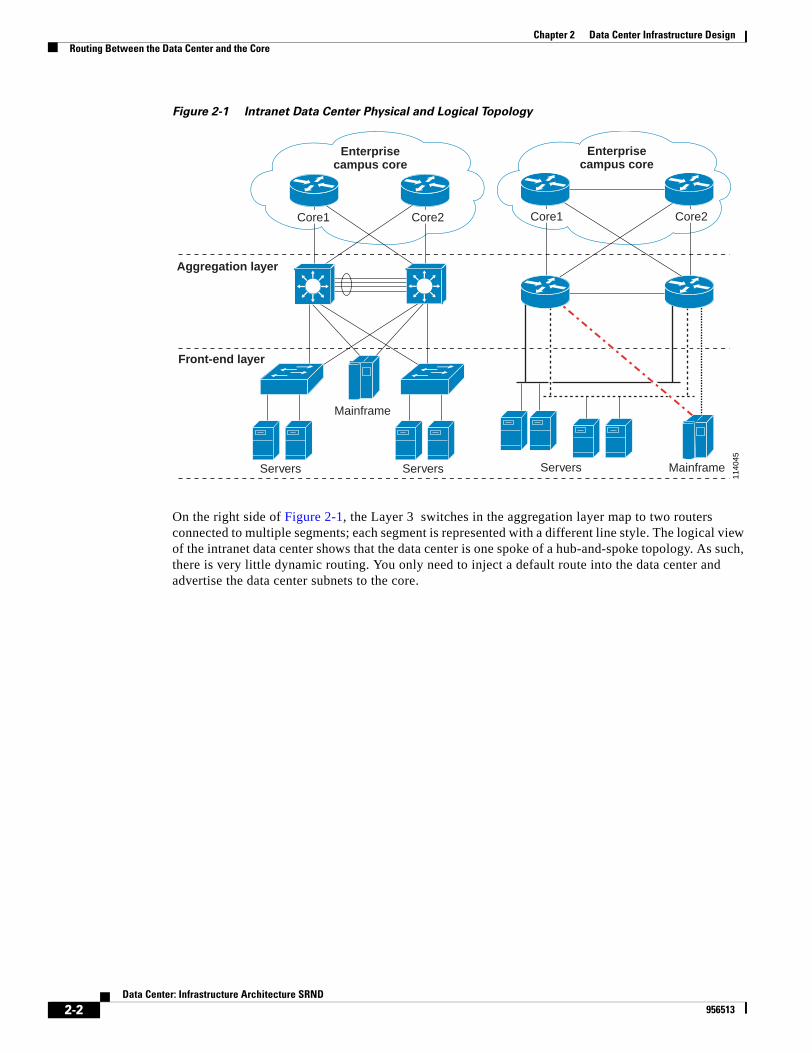
Figure 2-1 Intranet Data Center Physical and Logical Topology
On the right side of Figure 2-1, the Layer 3 switches in the aggregation layer map to two routers connected to multiple segments; each segment is represented with a different line style. The logical view of the intranet data center shows that the data center is one spoke of a hub-and-spoke topology. As such, there is very little dynamic routing. You only need to inject a default route into the data center and advertise the data center subnets to the core.
Enterprisecampus core
1140
45
Enterprisecampus core
Core1 Core2
Servers
Core1 Core2
Mainframe
Aggregation layer
Servers
Front-end layer
MainframeServers
2-2Data Center: Infrastructure Architecture SRND
956513
Chapter 2 Data Center Infrastructure DesignRouting Between the Data Center and the Core
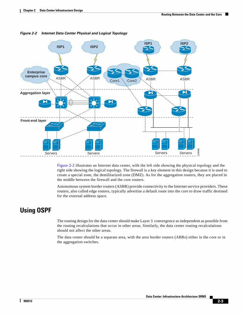
Figure 2-2 Internet Data Center Physical and Logical Topology
Figure 2-2 illustrates an Internet data center, with the left side showing the physical topology and the right side showing the logical topology. The firewall is a key element in this design because it is used to create a special zone, the demilitarized zone (DMZ). As for the aggregation routers, they are placed in the middle between the firewall and the core routers.
Autonomous system border routers (ASBR) provide connectivity to the Internet service providers. These routers, also called edge routers, typically advertise a default route into the core to draw traffic destined for the external address space.
Using OSPFThe routing design for the data center should make Layer 3 convergence as independent as possible from the routing recalculations that occur in other areas. Similarly, the data center routing recalculations should not affect the other areas.
The data center should be a separate area, with the area border routers (ABRs) either in the core or in the aggregation switches.
1140
46
ASBR ASBR
Servers
Enterprisecampus core
ISP1 ISP2ISP1 ISP2
Core1 Core2 ASBR ASBR
Aggregation layer
Servers
Front-end layer
Servers Servers
2-3Data Center: Infrastructure Architecture SRND
956513
Chapter 2 Data Center Infrastructure DesignRouting Between the Data Center and the Core
Figure 2-3 LSA Propagation After Failure in the Data Center
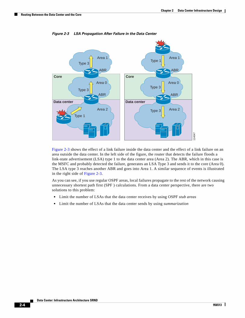
Figure 2-3 shows the effect of a link failure inside the data center and the effect of a link failure on an area outside the data center. In the left side of the figure, the router that detects the failure floods a link-state advertisement (LSA) type 1 to the data center area (Area 2). The ABR, which in this case is the MSFC and probably detected the failure, generates an LSA Type 3 and sends it to the core (Area 0). The LSA type 3 reaches another ABR and goes into Area 1. A similar sequence of events is illustrated in the right side of Figure 2-3.
As you can see, if you use regular OSPF areas, local failures propagate to the rest of the network causing unnecessary shortest path first (SPF ) calculations. From a data center perspective, there are two solutions to this problem:
• Limit the number of LSAs that the data center receives by using OSPF stub areas
• Limit the number of LSAs that the data center sends by using summarization
1140
47
Data center
Core
Type 3
Area 0
ABRType 3
Area 1
ABR
Area 2
Type 1
Data center
Core
Type 1
Area 0
ABR
Type 3
Area 1
ABR
Area 2Type 3
2-4Data Center: Infrastructure Architecture SRND
956513
Chapter 2 Data Center Infrastructure DesignRouting Between the Data Center and the Core
Figure 2-4 OSPF Stub Areas
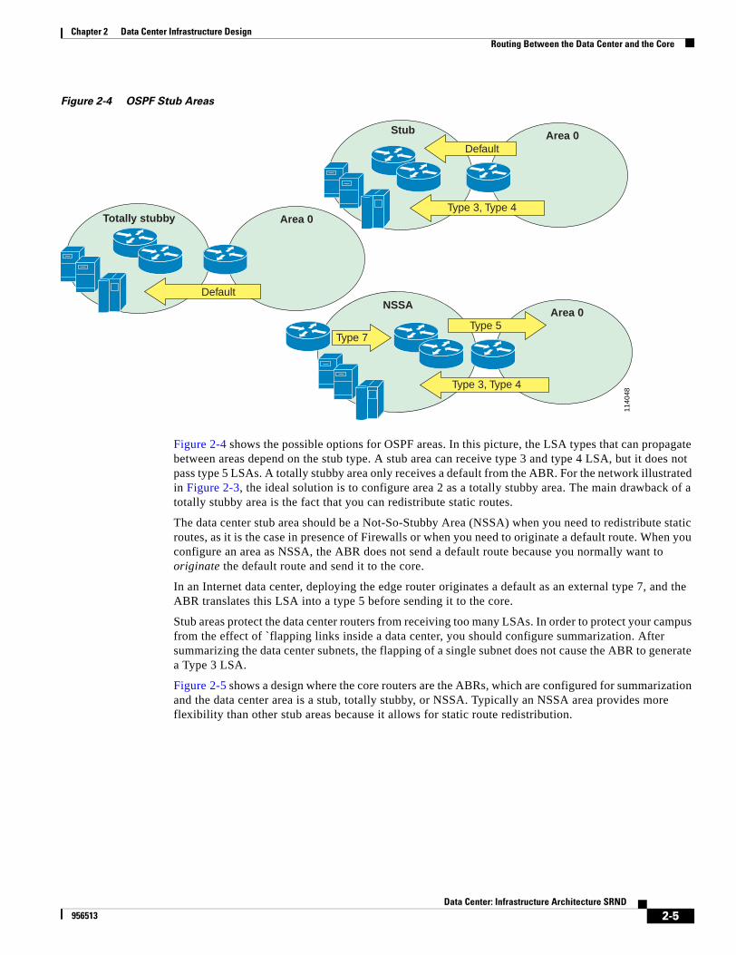
Figure 2-4 shows the possible options for OSPF areas. In this picture, the LSA types that can propagate between areas depend on the stub type. A stub area can receive type 3 and type 4 LSA, but it does not pass type 5 LSAs. A totally stubby area only receives a default from the ABR. For the network illustrated in Figure 2-3, the ideal solution is to configure area 2 as a totally stubby area. The main drawback of a totally stubby area is the fact that you can redistribute static routes.
The data center stub area should be a Not-So-Stubby Area (NSSA) when you need to redistribute static routes, as it is the case in presence of Firewalls or when you need to originate a default route. When you configure an area as NSSA, the ABR does not send a default route because you normally want to originate the default route and send it to the core.
In an Internet data center, deploying the edge router originates a default as an external type 7, and the ABR translates this LSA into a type 5 before sending it to the core.
Stub areas protect the data center routers from receiving too many LSAs. In order to protect your campus from the effect of `flapping links inside a data center, you should configure summarization. After summarizing the data center subnets, the flapping of a single subnet does not cause the ABR to generate a Type 3 LSA.
Figure 2-5 shows a design where the core routers are the ABRs, which are configured for summarization and the data center area is a stub, totally stubby, or NSSA. Typically an NSSA area provides more flexibility than other stub areas because it allows for static route redistribution.
1140
48
Totally stubby Area 0
Default
Stub Area 0
Type 3, Type 4
Default
NSSAArea 0
Type 3, Type 4
Type 5Type 7
2-5Data Center: Infrastructure Architecture SRND
956513
Chapter 2 Data Center Infrastructure DesignRouting Between the Data Center and the Core
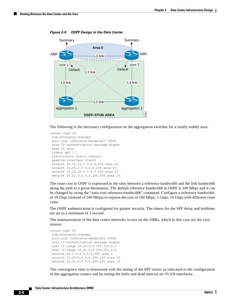
Figure 2-5 OSPF Design in the Data Center
The following is the necessary configuration on the aggregation switches for a totally stubby area:
router ospf 10 log-adjacency-changes auto-cost reference-bandwidth 10000 area 10 authentication message-digest area 10 nssa timers spf 1 1 redistribute static subnets passive-interface Vlan20 network 10.10.10.0 0.0.0.255 area 10 network 10.20.3.0 0.0.0.255 area 10 network 10.20.20.0 0.0.0.255 area 10 network 10.21.0.0 0.0.255.255 area 10
The route cost in OSPF is expressed as the ratio between a reference bandwidth and the link bandwidth along the path to a given destination. The default reference bandwidth in OSPF is 100 Mbps and it can be changed by using the “auto-cost reference-bandwidth” command. Configure a reference bandwidth of 10 Gbps (instead of 100 Mbps) to express the cost of 100 Mbps, 1 Gbps, 10 Gbps with different route costs.
The OSPF authentication is configured for greater security. The timers for the SPF delay and holdtime are set to a minimum of 1 second.
The summarization of the data center networks occurs on the ABRs, which in this case are the core routers:
router ospf 20 log-adjacency-changes auto-cost reference-bandwidth 10000 area 10 authentication message-digest area 10 range 10.20.0.0 255.255.0.0 area 10 range 10.21.0.0 255.255.0.0 network 10.0.0.0 0.0.0.255 area 0 network 10.20.0.0 0.0.255.255 area 10 network 10.21.0.0 0.0.255.255 area 10
The convergence time is minimized with the tuning of the SPF timers as indicated in the configuration of the aggregation routers and by tuning the hello and dead interval on VLAN interfaces:
7649
4
Summary Summary
ABR ABR
Area 0
aggregation 2aggregation 1
core 2core 1Default Default
OSPF-STUB AREA
L3 link
L3 link
L3 link
L3 linkL3 link
2-6Data Center: Infrastructure Architecture SRND
956513
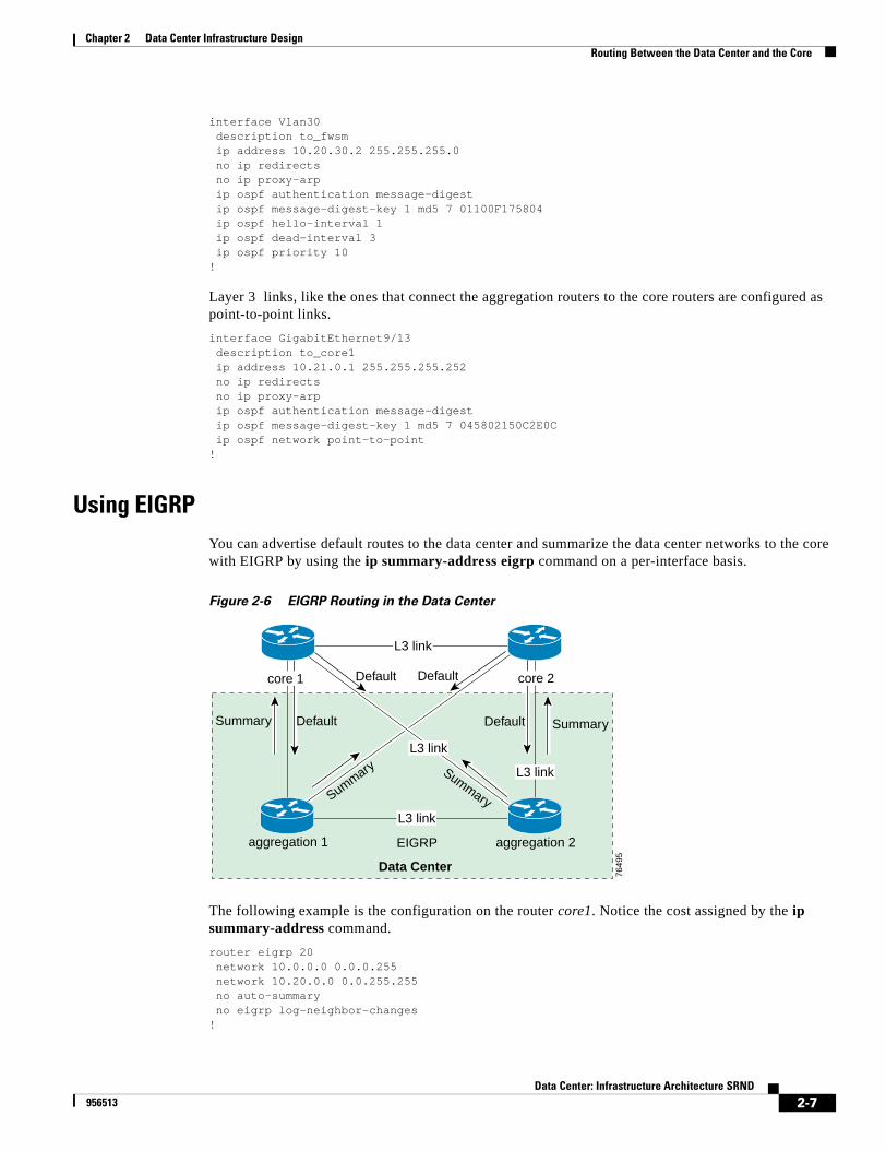
Chapter 2 Data Center Infrastructure DesignRouting Between the Data Center and the Core
interface Vlan30 description to_fwsm ip address 10.20.30.2 255.255.255.0 no ip redirects no ip proxy-arp ip ospf authentication message-digest ip ospf message-digest-key 1 md5 7 01100F175804 ip ospf hello-interval 1 ip ospf dead-interval 3 ip ospf priority 10!
Layer 3 links, like the ones that connect the aggregation routers to the core routers are configured as point-to-point links.
interface GigabitEthernet9/13 description to_core1 ip address 10.21.0.1 255.255.255.252 no ip redirects no ip proxy-arp ip ospf authentication message-digest ip ospf message-digest-key 1 md5 7 045802150C2E0C ip ospf network point-to-point!
Using EIGRPYou can advertise default routes to the data center and summarize the data center networks to the core with EIGRP by using the ip summary-address eigrp command on a per-interface basis.
Figure 2-6 EIGRP Routing in the Data Center
The following example is the configuration on the router core1. Notice the cost assigned by the ip summary-address command.
router eigrp 20 network 10.0.0.0 0.0.0.255 network 10.20.0.0 0.0.255.255 no auto-summary no eigrp log-neighbor-changes!
7649
5
Summary Summary
aggregation 2aggregation 1
Default
Data Center
EIGRP
Defaultcore 1
DefaultDefault
core 2
L3 link
Summary Summary
L3 link
L3 link
L3 link
2-7Data Center: Infrastructure Architecture SRND
956513
Chapter 2 Data Center Infrastructure DesignRouting Between the Data Center and the Core
interface GigabitEthernet4/7 description to_aggregation1 ip address 10.20.0.2 255.255.255.252 ip summary-address eigrp 20 0.0.0.0 0.0.0.0 200end!interface GigabitEthernet4/8 description to_aggregation2 ip address 10.20.0.10 255.255.255.252 ip summary-address eigrp 20 0.0.0.0 0.0.0.0 200end
It is important to configure a cost of 200 for the default route, which the core advertises to the data center. The core router automatically installs a NULL0 route for the same default route. If an edge router advertises a default route, as when accessing the Internet, the configured route must take precedence over the NULL0 route. This does not happen if you do not force the cost to be 200. Any traffic that reaches the core and does not match a route is black holed instead of being pushed to the edge routers.
The main limitation of this configuration is that the core routers keep advertising a default route to the aggregation routers in the data center whether they receive a default from the Internet edge or not. A better design involves filtering out all the routes that are injected into the data center with the exception of the default route.
router eigrp 20 network 10.0.0.0 0.0.0.255 network 10.20.0.0 0.0.255.255 distribute-list 10 out GigabitEthernet4/7 distribute-list 10 out GigabitEthernet4/8 no auto-summary no eigrp log-neighbor-changes!access-list 10 permit 0.0.0.0
On the aggregation router, configure all the VLAN interfaces to be “passive” but one in order to keep a Layer 3 route between the aggregation routers. Configure summarization on the specific Layer 3 links that connect to the core.
The configuration for aggregation1 follows:
router eigrp 20 passive-interface Vlan5 passive-interface Vlan20 network 10.20.0.0 0.0.255.255 no auto-summary no eigrp log-neighbor-changes!interface GigabitEthernet4/7 description to_mp_core1_tserv3 ip address 10.21.0.1 255.255.255.252 ip summary-address eigrp 20 10.20.0.0 255.255.0.0 5end
Designing Layer 3 SecurityWhen designing data center routing, you should take advantage of Layer 3 security features that minimize the risk of forwarding traffic to a rogue device. Dynamic routing protocols authentication such as OSPF MD5 authentication and EIGRP MD5 authentication help minimizing this risk. Figure 2-7
2-8Data Center: Infrastructure Architecture SRND
956513

Chapter 2 Data Center Infrastructure DesignSwitching Architecture for the Server Farm
shows a possible OSPF configuration in a data center, in this case the firewalls are running OSPF as well. Notice that because they operate as active/standby, both aggregation1 and aggregation2 become OSPF neighbor with only one firewall of the redundant firewall pair.
Figure 2-7 OSPF Authentication in the Data Center
Switching Architecture for the Server FarmThis section describes how to design the switching architecture for the server farm. It includes the following sections:
• Using Redundant Supervisors
• Designing Layer 2 in the Data Center
Using Redundant SupervisorsIOS Stateful SwitchOver (SSO) is an IOS feature that synchronizes the Layer 2 state between supervisors. SSO synchronizes the MAC address table, the Spanning-Tree state, the trunk state, and the EtherChannel state. IOS SSO is available in the Supervisor IOS release 12.2(17a)SX2. This functionality provided in Catalyst OS is called high availability (HA), which has been available since CatOS 5.4.
The service modules are unaffected when a supervisor switchover occurs, which means that their OS continues running and they can forward traffic. This is true for supervisor IOS SSO and CatOS HA because ports do not change state during switchover. However, this is not completely true for supervisor IOS Route Processor Redundancy (RPR+ ) because the protocols (including spanning tree) have to restart on the newly active supervisor.
1140
49
L3 link
Area 0M
D5
auth
enti
cati
on
ABR ABR
Aggregation 1
L3 li
nk
L3 li
nk
L3 link
Core1 Core2
OSPF-NSSA
Aggregation 2
MD
5au
then
tica
tio
n
MD
5au
then
tica
tio
n
MD5authentication
MD5
authentication
L3 link
Layer 2segment
MD5
authenticationLayer 2segment
L3 link
2-9Data Center: Infrastructure Architecture SRND
956513
Chapter 2 Data Center Infrastructure DesignSwitching Architecture for the Server Farm
RPR+ is the implementation of supervisor redundancy available in Supervisor IOS Release 12.1. RPR+ keeps the standby supervisor fully booted and synchronizes the configurations at runtime. When switchover occurs, RPR+ resets the ports and does not reset the line cards. In the meantime, the standby supervisor comes online and restarts the protocols. However, you must reprogram the routing table and it takes about 30 to 60 seconds for switchover to complete.
For more information about this feature, refer to the following web page: http://www.cisco.com/univercd/cc/td/doc/product/lan/cat6000/12_1e/swconfig/redund.htm
Layer 2 Data Center DesignThis section outlines how to design the Layer 2 domain in the data center to avoid loops and to minimize the convergence time by using specific features available on Catalyst switches.
The Layer 2 domain starts at the access layer and terminates at the device providing the default gateway. The Layer 2 domain is made of several VLANs that you assign based on how you want to segregate the server farms. There are also VLANs that do not reach the access switches that are just used by service modules and service appliances and trunked between the aggregation switches.
Note Do not disable STP on any of the VLANs.
We recommend that you use Rapid PVST+ (RPVST+) or MST for improved stability and faster convergence. Remember, 802.1w assigns roles to the ports, and you can control port assignment with PortFast and TrunkFast. An edge port, which is a port that connects to a host or a service appliance, does not need to change state from blocking, to learning, and to forwarding. To designate a port as edge, you must manually enable PortFast or TrunkFast manually.
Using Three-Tier and Two-Tier Network Designs
An enterprise data center network in most instances will have a three-tier design with an Ethernet access layer and an aggregation layer connected to the campus core layer. Small and medium data centers will have a two-tier design, as shown in the left side of Figure 2-8(a) with the Layer 3 access layer connected to the backbone core (collapsed core and distribution layers). Three-tier designs, illustrated in Figure 2-8(b), allow greater scalability in the number of access ports, but a two-tier design is ideal for small server farms.
2-10Data Center: Infrastructure Architecture SRND
956513

Chapter 2 Data Center Infrastructure DesignSwitching Architecture for the Server Farm
Figure 2-8 Two-Tier and Three-Tier Data Center Network Designs
Layer 2 and Layer 3 Access Design
We recommend that the server farm always be segregated from the core of the campus network using a Layer 3 device, typically a router. Layer 3 segregation protects the core devices from broadcasts and flooding that could by generated by servers in a specific segment. The device that supports the default gateway function for the servers is the boundary between the Layer 2 and Layer 3 domains.
In a two-tier design the access layer is at Layer 3, which means that the access switches are also routers, and their connection to the core utilizes Layer 3 links. However, this doesn’t mean that every port on these switches is a Layer 3 port. On the contrary, Layer 2 segments connect these switches to support clustering protocols and server-to-server communication for servers that require Layer 2 adjacency.
You can design three-tier network with Layer 3 access, shown in Figure 2-9(a) or with Layer 2 access, shown in Figure 2-9(b). When the data center network uses a three-tier design, there are separate aggregation and access layers and the access layer typically uses switches configured for pure Layer 2 forwarding, shown in Figure 2-9(a) . This design makes it easier to assign multiple servers to the same load balancers and firewalls installed at the aggregation layer. The segregation between the Layer 2 domain of the server farm and the core of the network is still achieved with Layer 3 devices, which in this case are the Layer 3 aggregation switches.
The access layer of a three-tier data center network can also be at Layer 3, shown in Figure 2-9(b), but in this case it becomes more complex to design the network with service devices, such as load balancers and firewalls that must be shared among multiple access switches.
1140
50
Core
Core(A) (B)
2-11Data Center: Infrastructure Architecture SRND
956513
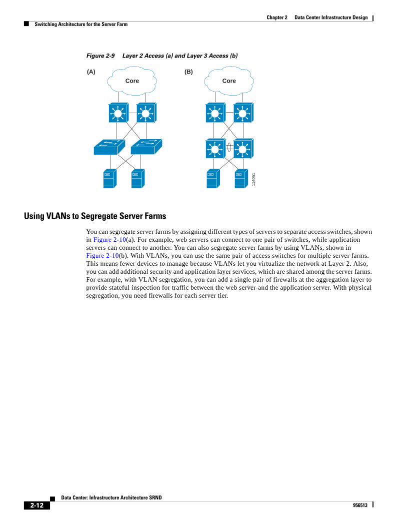
Chapter 2 Data Center Infrastructure DesignSwitching Architecture for the Server Farm
Figure 2-9 Layer 2 Access (a) and Layer 3 Access (b)
Using VLANs to Segregate Server Farms
You can segregate server farms by assigning different types of servers to separate access switches, shown in Figure 2-10(a). For example, web servers can connect to one pair of switches, while application servers can connect to another. You can also segregate server farms by using VLANs, shown in Figure 2-10(b). With VLANs, you can use the same pair of access switches for multiple server farms. This means fewer devices to manage because VLANs let you virtualize the network at Layer 2. Also, you can add additional security and application layer services, which are shared among the server farms. For example, with VLAN segregation, you can add a single pair of firewalls at the aggregation layer to provide stateful inspection for traffic between the web server-and the application server. With physical segregation, you need firewalls for each server tier.
1140
51
Core
(A) (B)
Core
2-12Data Center: Infrastructure Architecture SRND
956513
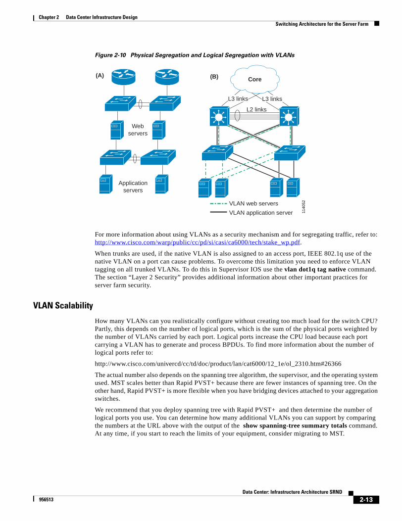
Chapter 2 Data Center Infrastructure DesignSwitching Architecture for the Server Farm
Figure 2-10 Physical Segregation and Logical Segregation with VLANs
For more information about using VLANs as a security mechanism and for segregating traffic, refer to: http://www.cisco.com/warp/public/cc/pd/si/casi/ca6000/tech/stake_wp.pdf.
When trunks are used, if the native VLAN is also assigned to an access port, IEEE 802.1q use of the native VLAN on a port can cause problems. To overcome this limitation you need to enforce VLAN tagging on all trunked VLANs. To do this in Supervisor IOS use the vlan dot1q tag native command. The section “Layer 2 Security” provides additional information about other important practices for server farm security.
VLAN Scalability
How many VLANs can you realistically configure without creating too much load for the switch CPU? Partly, this depends on the number of logical ports, which is the sum of the physical ports weighted by the number of VLANs carried by each port. Logical ports increase the CPU load because each port carrying a VLAN has to generate and process BPDUs. To find more information about the number of logical ports refer to:
http://www.cisco.com/univercd/cc/td/doc/product/lan/cat6000/12_1e/ol_2310.htm#26366
The actual number also depends on the spanning tree algorithm, the supervisor, and the operating system used. MST scales better than Rapid PVST+ because there are fewer instances of spanning tree. On the other hand, Rapid PVST+ is more flexible when you have bridging devices attached to your aggregation switches.
We recommend that you deploy spanning tree with Rapid PVST+ and then determine the number of logical ports you use. You can determine how many additional VLANs you can support by comparing the numbers at the URL above with the output of the show spanning-tree summary totals command. At any time, if you start to reach the limits of your equipment, consider migrating to MST.
1140
52
Webservers
Applicationservers
(A) (B) Core
L2 links
L3 links L3 links
VLAN web servers
VLAN application server
2-13Data Center: Infrastructure Architecture SRND
956513
Chapter 2 Data Center Infrastructure DesignSwitching Architecture for the Server Farm
Using Virtual Trunking Protocol
Virtual Trunking Protocol (VTP) is a Layer 2 messaging protocol that maintains VLAN configuration consistency by managing the addition, deletion, and renaming of VLANs within a VTP domain. A VTP domain (also called a VLAN management domain) is made up of one or more network devices that share the same VTP domain name and that are interconnected with trunks. VTPv1 and VTPv2 allow misconfigurations that make it possible to accidentally delete a VLAN from a given VTP domain. This is fixed in VTPv3, which is not yet available in Supervisor IOS. For this reason, this design guide uses VTP transparent mode.
Note For more information about VTP, refer to the publication 13414 “Best Practices for Catalyst 4000, 5000, and 6000 Series Switch Configuration and Management” at http://www.cisco.com/warp/public/473/103.html and the publication 24330 “Best Practices for Catalyst 6500/6000 Series and Catalyst 4500/4000 Series Switches Running Cisco IOS” at http://www.cisco.com/warp/public/473/185.pdf.
Choosing a Spanning-Tree Algorithm
This section describes the different spanning tree algorithms available and some of the benefits and drawbacks of each one. It includes the following topics:
• 802.1w
• Rapid PVST+
• MST
802.1w
The 802.1w protocol is the standard for rapid spanning tree convergence, and it can be deployed in conjunction with either of the following protocols:
• Cisco Per VLAN Spanning Tree Plus (PVST+)—This combination is called Rapid PVST+
• 802.1s+—This combination is called Multiple Instance STP (MST)
802.1w is enabled by default when running spanning tree in Rapid PVST+ or MST mode. The key features of 802.1w are the following:
• Convergence is accelerated by a handshake (proposal agreement mechanism)
• No need to enable BackboneFast or UplinkFast
In terms of convergence, the spanning tree algorithms using 802.1w are much faster, especially because of the proposal agreement mechanism that allows a switch to decide new port roles by exchanging proposals with its neighbors. BPDUs are still sent every 2 seconds by default (hello time).
If three BPDUs are missed, spanning tree recalculates the topology, which takes less than 1 second for the rapid spanning tree (802.1w). Therefore, you could say that the spanning tree convergence time is around 6 seconds. Because the data center is made of point-to-point links, the only failures will be physical failures of the networking devices or links. This means that the actual convergence time is below 1 second rather than 6 seconds. The scenario where BPDUs are lost is actually likely to be caused by unidirectional links which can cause Layer 2 loops, and to prevent this specific problem, you can use Loopguard.
2-14Data Center: Infrastructure Architecture SRND
956513
Chapter 2 Data Center Infrastructure DesignSwitching Architecture for the Server Farm
Rapid PVST+
Rapid PVST+ combines the fast convergence of 802.1w with the flexibility of PVST+. For more information about Rapid PVST+ refer to the document “Implementing Rapid Spanning Tree and Multiple Spanning Tree” at: http://www.cisco.com/univercd/cc/td/doc/solution/esm/stpimp/rstpmstp.pdf.
Rapid PVST+ allows a redundant pair of bridging appliances attached to aggregation switches without the need to filter BPDUs. This is explained in further details in the section "Using Spanning Tree with Bridging Appliances." Also, you can migrate to Rapid PVST+ from PVST+ with a single command statement and it is easier to configure uplink load balancing compared to MST.
To ensure compatibility between switches running Rapid PVST+ (or PVST+) and switches running 802.1d use Common Spanning Tree (CST), which is the spanning tree built on VLAN 1. Cisco switches running Rapid PVST+ or PVST+ send proprietary BPDUs for all the VLANs with the exception of VLAN 1. VLAN 1 uses IEEE BPDUs and generates a CST with non-Cisco switches running IEEE 802.1d.
MST
MST scales better with many VLANs and trunks, as described in the section “VLAN Scalability.” However, MST shows inferior performance with Layer 2 appliances and complex configurations.
The key features of MST include the following:
• One single BPDU has the information about all instances and the IST
• Up to 16 instances are possible
The MST protocol allows mapping multiple VLANs to a single spanning tree instance, which reduces the load on the CPU required to maintain the Layer 2 topology when many VLANs are configured. With 802.1s, a default instance is always present, called Internal Spanning Tree (IST) or the MST instance 0.
The switch uses IST to build a shared tree for compatibility with regions that run Common Spanning Tree (CST). The IST information is carried on BPDUs on all the ports. Do not map VLANs to the IST because the IST is only for compatibility with other regions.
Using Loopguard and UDLD
Spanning tree is designed for shared media as well as point-to-point links and assumes that missing BPDUs is a symptom of a device failure or of a link failure. In the case of point-to-point links, the neighboring switch immediately detects the physical failure of a link or of a network device because a link is down and it is using BPDUs to detect a change in link status is not necessary. On a point-to-point link, BPDUs should always be received. Missing BPDUs indicates a link has become unidirectional because of the failure of a transceiver or a software bug on a neighboring device.
If a port starts forwarding because of missed BPDUs, it is likely to cause a Layer 2 loop that brings down the network. The feature that fixes this problem is called Loopguard. As you can see from Figure 2-11, spanning tree by itself cannot tell the difference between a bug, over subscription or a unidirectional link and a broken link between the two aggregation switches.
2-15Data Center: Infrastructure Architecture SRND
956513
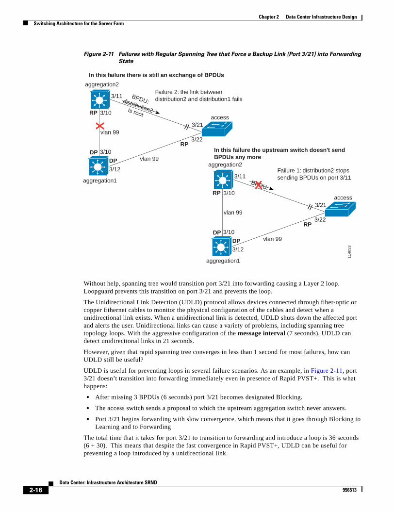
Chapter 2 Data Center Infrastructure DesignSwitching Architecture for the Server Farm
Figure 2-11 Failures with Regular Spanning Tree that Force a Backup Link (Port 3/21) into Forwarding
State
Without help, spanning tree would transition port 3/21 into forwarding causing a Layer 2 loop. Loopguard prevents this transition on port 3/21 and prevents the loop.
The Unidirectional Link Detection (UDLD) protocol allows devices connected through fiber-optic or copper Ethernet cables to monitor the physical configuration of the cables and detect when a unidirectional link exists. When a unidirectional link is detected, UDLD shuts down the affected port and alerts the user. Unidirectional links can cause a variety of problems, including spanning tree topology loops. With the aggressive configuration of the message interval (7 seconds), UDLD can detect unidirectional links in 21 seconds.
However, given that rapid spanning tree converges in less than 1 second for most failures, how can UDLD still be useful?
UDLD is useful for preventing loops in several failure scenarios. As an example, in Figure 2-11, port 3/21 doesn’t transition into forwarding immediately even in presence of Rapid PVST+. This is what happens:
• After missing 3 BPDUs (6 seconds) port 3/21 becomes designated Blocking.
• The access switch sends a proposal to which the upstream aggregation switch never answers.
• Port 3/21 begins forwarding with slow convergence, which means that it goes through Blocking to Learning and to Forwarding
The total time that it takes for port 3/21 to transition to forwarding and introduce a loop is 36 seconds (6 + 30). This means that despite the fast convergence in Rapid PVST+, UDLD can be useful for preventing a loop introduced by a unidirectional link.
BPDU:distribution2is root
1140
53
aggregation2
aggregation1
DP
RP
vlan 993/21
3/22
3/10
3/11Failure 2: the link betweendistribution2 and distribution1 fails
3/12
3/10
DP vlan 99
RP
access
X
aggregation2
aggregation1
DP
RP
vlan 993/21
3/22
3/10
3/11
3/12
3/10
DP vlan 99
RP
access
Failure 1: distribution2 stopssending BPDUs on port 3/11
BPDU:X
In this failure there is still an exchange of BPDUs
In this failure the upstream switch doesn't sendBPDUs any more
2-16Data Center: Infrastructure Architecture SRND
956513
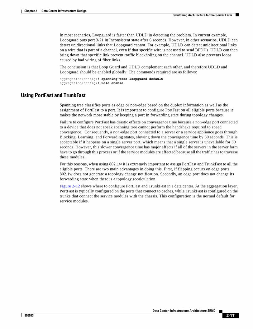
Chapter 2 Data Center Infrastructure DesignSwitching Architecture for the Server Farm
In most scenarios, Loopguard is faster than UDLD in detecting the problem. In current example, Loopguard puts port 3/21 in Inconsistent state after 6 seconds. However, in other scenarios, UDLD can detect unidirectional links that Loopguard cannot. For example, UDLD can detect unidirectional links on a wire that is part of a channel, even if that specific wire is not used to send BPDUs. UDLD can then bring down that specific link prevent traffic blackholing on the channel. UDLD also prevents loops caused by bad wiring of fiber links.
The conclusion is that Loop Guard and UDLD complement each other, and therefore UDLD and Loopguard should be enabled globally: The commands required are as follows:
aggregation(config)# spanning-tree loopguard defaultaggregation(config)# udld enable
Using PortFast and TrunkFast
Spanning tree classifies ports as edge or non-edge based on the duplex information as well as the assignment of PortFast to a port. It is important to configure PortFast on all eligible ports because it makes the network more stable by keeping a port in forwarding state during topology changes.
Failure to configure PortFast has drastic effects on convergence time because a non-edge port connected to a device that does not speak spanning tree cannot perform the handshake required to speed convergence. Consequently, a non-edge port connected to a server or a service appliance goes through Blocking, Learning, and Forwarding states, slowing down the convergence time by 30 seconds. This is acceptable if it happens on a single server port, which means that a single server is unavailable for 30 seconds. However, this slower convergence time has major effects if all of the servers in the server farm have to go through this process or if the service modules are affected because all the traffic has to traverse these modules.
For this reasons, when using 802.1w it is extremely important to assign PortFast and TrunkFast to all the eligible ports. There are two main advantages in doing this. First, if flapping occurs on edge ports, 802.1w does not generate a topology change notification. Secondly, an edge port does not change its forwarding state when there is a topology recalculation.
Figure 2-12 shows where to configure PortFast and TrunkFast in a data center. At the aggregation layer, PortFast is typically configured on the ports that connect to caches, while TrunkFast is configured on the trunks that connect the service modules with the chassis. This configuration is the normal default for service modules.
2-17Data Center: Infrastructure Architecture SRND
956513
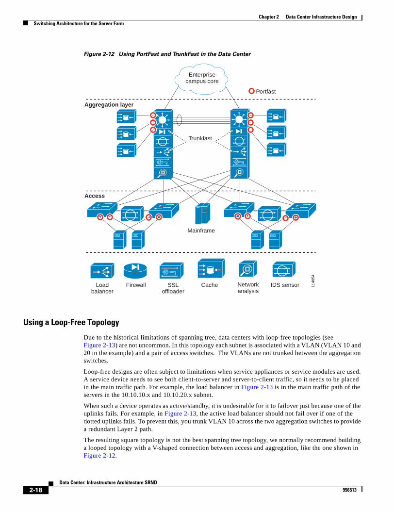
Chapter 2 Data Center Infrastructure DesignSwitching Architecture for the Server Farm
Figure 2-12 Using PortFast and TrunkFast in the Data Center
Using a Loop-Free Topology
Due to the historical limitations of spanning tree, data centers with loop-free topologies (see Figure 2-13) are not uncommon. In this topology each subnet is associated with a VLAN (VLAN 10 and 20 in the example) and a pair of access switches. The VLANs are not trunked between the aggregation switches.
Loop-free designs are often subject to limitations when service appliances or service modules are used. A service device needs to see both client-to-server and server-to-client traffic, so it needs to be placed in the main traffic path. For example, the load balancer in Figure 2-13 is in the main traffic path of the servers in the 10.10.10.x and 10.10.20.x subnet.
When such a device operates as active/standby, it is undesirable for it to failover just because one of the uplinks fails. For example, in Figure 2-13, the active load balancer should not fail over if one of the dotted uplinks fails. To prevent this, you trunk VLAN 10 across the two aggregation switches to provide a redundant Layer 2 path.
The resulting square topology is not the best spanning tree topology, we normally recommend building a looped topology with a V-shaped connection between access and aggregation, like the one shown in Figure 2-12.
1140
54
Mainframe
Aggregation layer
Access
Loadbalancer
Firewall SSLoffloader
Cache Networkanalysis
IDS sensor
Enterprisecampus core
Portfast
Trunkfast
2-18Data Center: Infrastructure Architecture SRND
956513
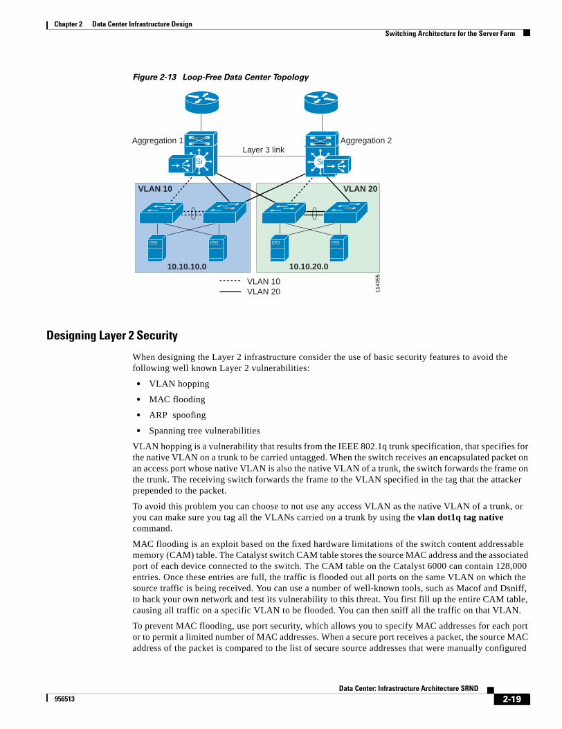
Chapter 2 Data Center Infrastructure DesignSwitching Architecture for the Server Farm
Figure 2-13 Loop-Free Data Center Topology
Designing Layer 2 Security
When designing the Layer 2 infrastructure consider the use of basic security features to avoid the following well known Layer 2 vulnerabilities:
• VLAN hopping
• MAC flooding
• ARP spoofing
• Spanning tree vulnerabilities
VLAN hopping is a vulnerability that results from the IEEE 802.1q trunk specification, that specifies for the native VLAN on a trunk to be carried untagged. When the switch receives an encapsulated packet on an access port whose native VLAN is also the native VLAN of a trunk, the switch forwards the frame on the trunk. The receiving switch forwards the frame to the VLAN specified in the tag that the attacker prepended to the packet.
To avoid this problem you can choose to not use any access VLAN as the native VLAN of a trunk, or you can make sure you tag all the VLANs carried on a trunk by using the vlan dot1q tag native command.
MAC flooding is an exploit based on the fixed hardware limitations of the switch content addressable memory (CAM) table. The Catalyst switch CAM table stores the source MAC address and the associated port of each device connected to the switch. The CAM table on the Catalyst 6000 can contain 128,000 entries. Once these entries are full, the traffic is flooded out all ports on the same VLAN on which the source traffic is being received. You can use a number of well-known tools, such as Macof and Dsniff, to hack your own network and test its vulnerability to this threat. You first fill up the entire CAM table, causing all traffic on a specific VLAN to be flooded. You can then sniff all the traffic on that VLAN.
To prevent MAC flooding, use port security, which allows you to specify MAC addresses for each port or to permit a limited number of MAC addresses. When a secure port receives a packet, the source MAC address of the packet is compared to the list of secure source addresses that were manually configured
1140
55
Layer 3 linkAggregation 1 Aggregation 2
VLAN 10VLAN 20
VLAN 10 VLAN 20
Si
10.10.10.0 10.10.20.0
Si
2-19Data Center: Infrastructure Architecture SRND
956513
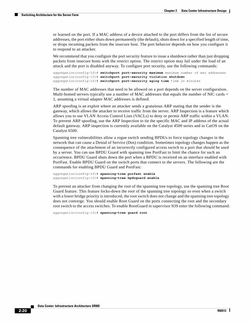
Chapter 2 Data Center Infrastructure DesignSwitching Architecture for the Server Farm
or learned on the port. If a MAC address of a device attached to the port differs from the list of secure addresses, the port either shuts down permanently (the default), shuts down for a specified length of time, or drops incoming packets from the insecure host. The port behavior depends on how you configure it to respond to an attacker.
We recommend that you configure the port security feature to issue a shutdown rather than just dropping packets from insecure hosts with the restrict option. The restrict option may fail under the load of an attack and the port is disabled anyway. To configure port security, use the following commands:
aggregation(config-if)# switchport port-security maximum maximum number of mac addressesaggregation(config-if)# switchport port-security violation shutdownaggregation(config-if)# switchport port-security aging time time in minutes
The number of MAC addresses that need to be allowed on a port depends on the server configuration. Multi-homed servers typically use a number of MAC addresses that equals the number of NIC cards + 1, assuming a virtual adapter MAC addresses is defined.
ARP spoofing is an exploit where an attacker sends a gratuitous ARP stating that the sender is the gateway, which allows the attacker to receive traffic from the server. ARP Inspection is a feature which allows you to use VLAN Access Control Lists (VACLs) to deny or permit ARP traffic within a VLAN. To prevent ARP spoofing, use the ARP Inspection to tie the specific MAC and IP address of the actual default gateway. ARP inspection is currently available on the Catalyst 4500 series and in CatOS on the Catalyst 6500.
Spanning tree vulnerabilities allow a rogue switch sending BPDUs to force topology changes in the network that can cause a Denial of Service (Dos) condition. Sometimes topology changes happen as the consequence of the attachment of an incorrectly configured access switch to a port that should be used by a server. You can use BPDU Guard with spanning tree PortFast to limit the chance for such an occurrence. BPDU Guard shuts down the port when a BPDU is received on an interface enabled with PortFast. Enable BPDU Guard on the switch ports that connect to the servers. The following are the commands for enabling BPDU Guard and PortFast:
aggregation(config-if)# spanning-tree porfast enableaggregation(config-if)# spanning-tree bpduguard enable
To prevent an attacker from changing the root of the spanning tree topology, use the spanning tree Root Guard feature. This feature locks-down the root of the spanning tree topology so even when a switch with a lower bridge priority is introduced, the root switch does not change and the spanning tree topology does not converge. You should enable Root Guard on the ports connecting the root and the secondary root switch to the access switches. To enable RootGuard in supervisor IOS enter the following command:
aggregation(config-if)# spanning-tree guard root
2-20Data Center: Infrastructure Architecture SRND
956513
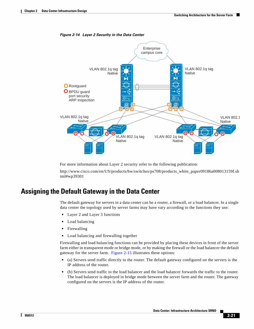
Chapter 2 Data Center Infrastructure DesignSwitching Architecture for the Server Farm
Figure 2-14 Layer 2 Security in the Data Center
For more information about Layer 2 security refer to the following publication:
http://www.cisco.com/en/US/products/hw/switches/ps708/products_white_paper09186a008013159f.shtml#wp39301
Assigning the Default Gateway in the Data CenterThe default gateway for servers in a data center can be a router, a firewall, or a load balancer. In a single data center the topology used by server farms may have vary according to the functions they use:
• Layer 2 and Layer 3 functions
• Load balancing
• Firewalling
• Load balancing and firewalling together
Firewalling and load balancing functions can be provided by placing these devices in front of the server farm either in transparent mode or bridge mode, or by making the firewall or the load balancer the default gateway for the server farm. Figure 2-15 illustrates these options:
• (a) Servers send traffic directly to the router. The default gateway configured on the servers is the IP address of the router.
• (b) Servers send traffic to the load balancer and the load balancer forwards the traffic to the router. The load balancer is deployed in bridge mode between the server farm and the router. The gateway configured on the servers is the IP address of the router.
Enterprisecampus core
Rootguard
BPDU guardport securityARP inspection
VLAN 802.1q tagNative
VLAN 802.1q tagNative
VLAN 802.1q tagNative
VLAN 802.1Native
VLAN 802.1q tagNative
VLAN 802.1q tagNative
2-21Data Center: Infrastructure Architecture SRND
956513
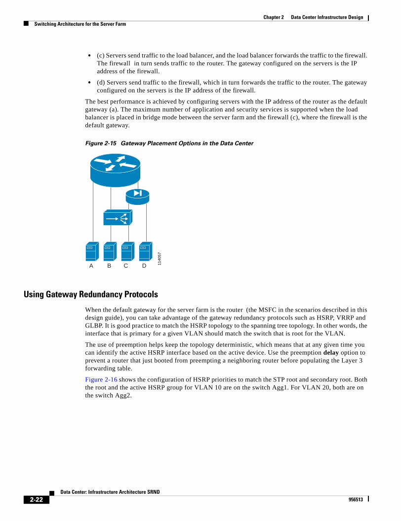
Chapter 2 Data Center Infrastructure DesignSwitching Architecture for the Server Farm
• (c) Servers send traffic to the load balancer, and the load balancer forwards the traffic to the firewall. The firewall in turn sends traffic to the router. The gateway configured on the servers is the IP address of the firewall.
• (d) Servers send traffic to the firewall, which in turn forwards the traffic to the router. The gateway configured on the servers is the IP address of the firewall.
The best performance is achieved by configuring servers with the IP address of the router as the default gateway (a). The maximum number of application and security services is supported when the load balancer is placed in bridge mode between the server farm and the firewall (c), where the firewall is the default gateway.
Figure 2-15 Gateway Placement Options in the Data Center
Using Gateway Redundancy Protocols
When the default gateway for the server farm is the router (the MSFC in the scenarios described in this design guide), you can take advantage of the gateway redundancy protocols such as HSRP, VRRP and GLBP. It is good practice to match the HSRP topology to the spanning tree topology. In other words, the interface that is primary for a given VLAN should match the switch that is root for the VLAN.
The use of preemption helps keep the topology deterministic, which means that at any given time you can identify the active HSRP interface based on the active device. Use the preemption delay option to prevent a router that just booted from preempting a neighboring router before populating the Layer 3 forwarding table.
Figure 2-16 shows the configuration of HSRP priorities to match the STP root and secondary root. Both the root and the active HSRP group for VLAN 10 are on the switch Agg1. For VLAN 20, both are on the switch Agg2.
1140
57
A DCB
2-22Data Center: Infrastructure Architecture SRND
956513
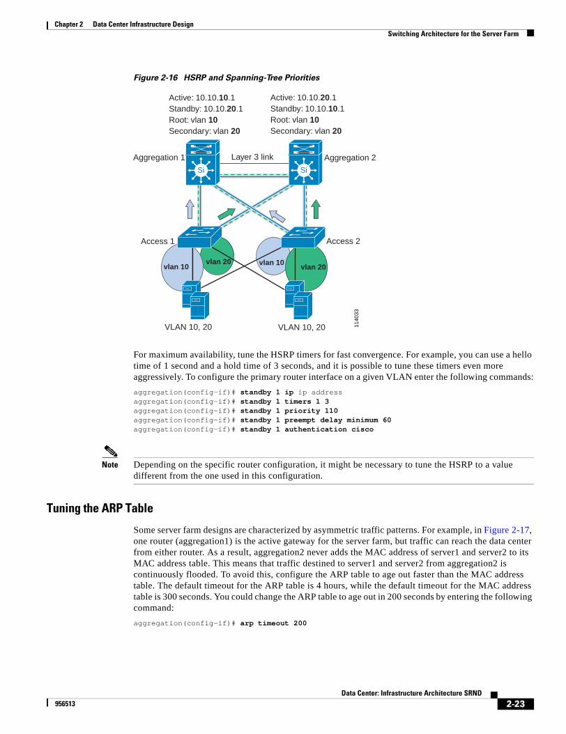
Chapter 2 Data Center Infrastructure DesignSwitching Architecture for the Server Farm
Figure 2-16 HSRP and Spanning-Tree Priorities
For maximum availability, tune the HSRP timers for fast convergence. For example, you can use a hello time of 1 second and a hold time of 3 seconds, and it is possible to tune these timers even more aggressively. To configure the primary router interface on a given VLAN enter the following commands:
aggregation(config-if)# standby 1 ip ip addressaggregation(config-if)# standby 1 timers 1 3aggregation(config-if)# standby 1 priority 110aggregation(config-if)# standby 1 preempt delay minimum 60aggregation(config-if)# standby 1 authentication cisco
Note Depending on the specific router configuration, it might be necessary to tune the HSRP to a value different from the one used in this configuration.
Tuning the ARP Table
Some server farm designs are characterized by asymmetric traffic patterns. For example, in Figure 2-17, one router (aggregation1) is the active gateway for the server farm, but traffic can reach the data center from either router. As a result, aggregation2 never adds the MAC address of server1 and server2 to its MAC address table. This means that traffic destined to server1 and server2 from aggregation2 is continuously flooded. To avoid this, configure the ARP table to age out faster than the MAC address table. The default timeout for the ARP table is 4 hours, while the default timeout for the MAC address table is 300 seconds. You could change the ARP table to age out in 200 seconds by entering the following command:
aggregation(config-if)# arp timeout 200
1140
33
Layer 3 link
vlan 20vlan 10 vlan 20
vlan 10
Aggregation 1
Access 1 Access 2
Aggregation 2
VLAN 10, 20 VLAN 10, 20
Active: 10.10.10.1Standby: 10.10.20.1Root: vlan 10Secondary: vlan 20
Active: 10.10.20.1Standby: 10.10.10.1Root: vlan 10Secondary: vlan 20
Si Si
2-23Data Center: Infrastructure Architecture SRND
956513
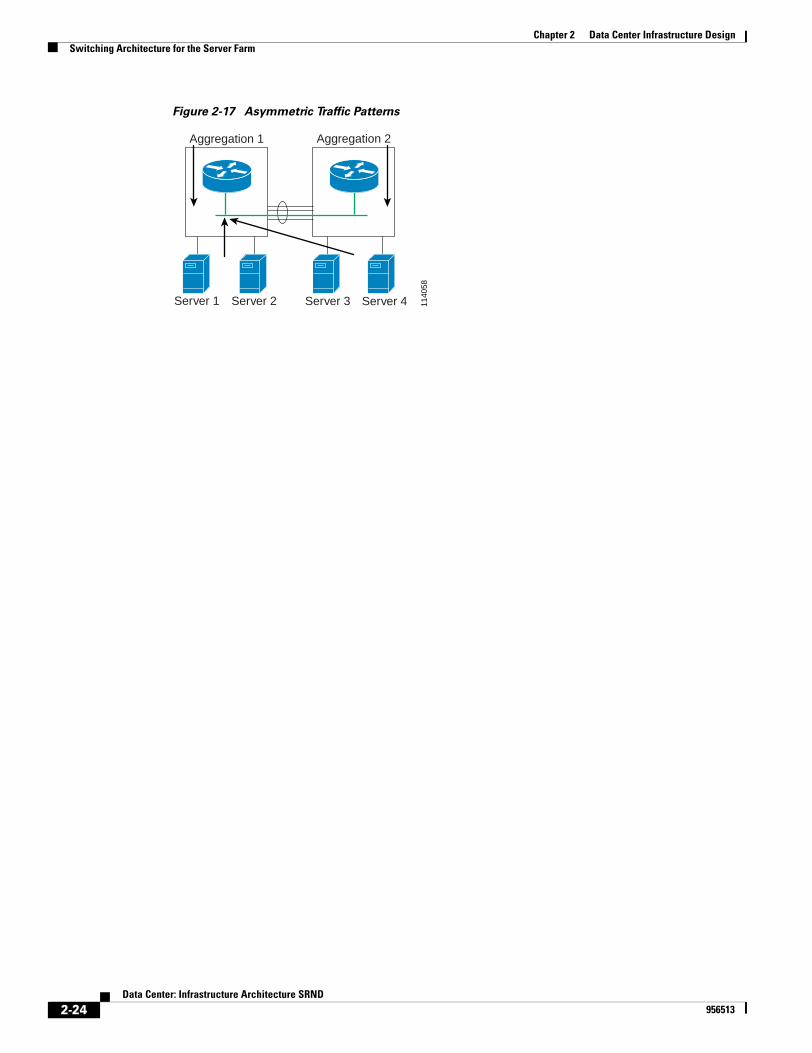
Chapter 2 Data Center Infrastructure DesignSwitching Architecture for the Server Farm
Figure 2-17 Asymmetric Traffic Patterns
1140
58
Aggregation 1 Aggregation 2
Server 1 Server 2 Server 3 Server 4
2-24Data Center: Infrastructure Architecture SRND
956513
Data C956513
C H A P T E R 3
HA Connectivity for Servers and Mainframes: NIC Teaming and OSA/OSPF DesignThis chapter provides information about server connectivity with NIC teaming and mainframe connectivity. It includes the following sections:
• Overview, page 3-1
• NIC Teaming Architecture Details, page 3-7
• Mainframe OSA and OSPF Architecture Details, page 3-20
• Configuration Details, page 3-26
OverviewFigure 3-1 shows a high-level view of the Cisco data center architecture, which is described in detail in "Data Center Infrastructure Design." As shown, the design follows the proven Cisco multilayer architecture, using core, aggregation, and access layers. Network devices are deployed in redundant pairs to avoid a single point of failure. Figure 3-1shows each server connected with two wires to two different access switches and a mainframe connected to two aggregation switches.
This document addresses the issues surrounding the deployment of servers with multiple network interfaces in the enterprise data center. The focus of this document is designing the attachment between the servers and the network, and it explains the following topics:
• Designs with one link active and one link standby
• Designs with all the links active
• How to increase the throughput available to the server for the outbound direction of the traffic (server-to-client)
• How to increase the throughput available to the server for both inbound and outbound direction of the traffic
• How to design network security when using the NIC teaming options
This document provides some background information about IBM mainframes and describes how to integrate mainframes into the Layer 2/Layer 3 infrastructure specifically from the point of view of IP addressing and routing.
3-1enter: Infrastructure Architecture SRND
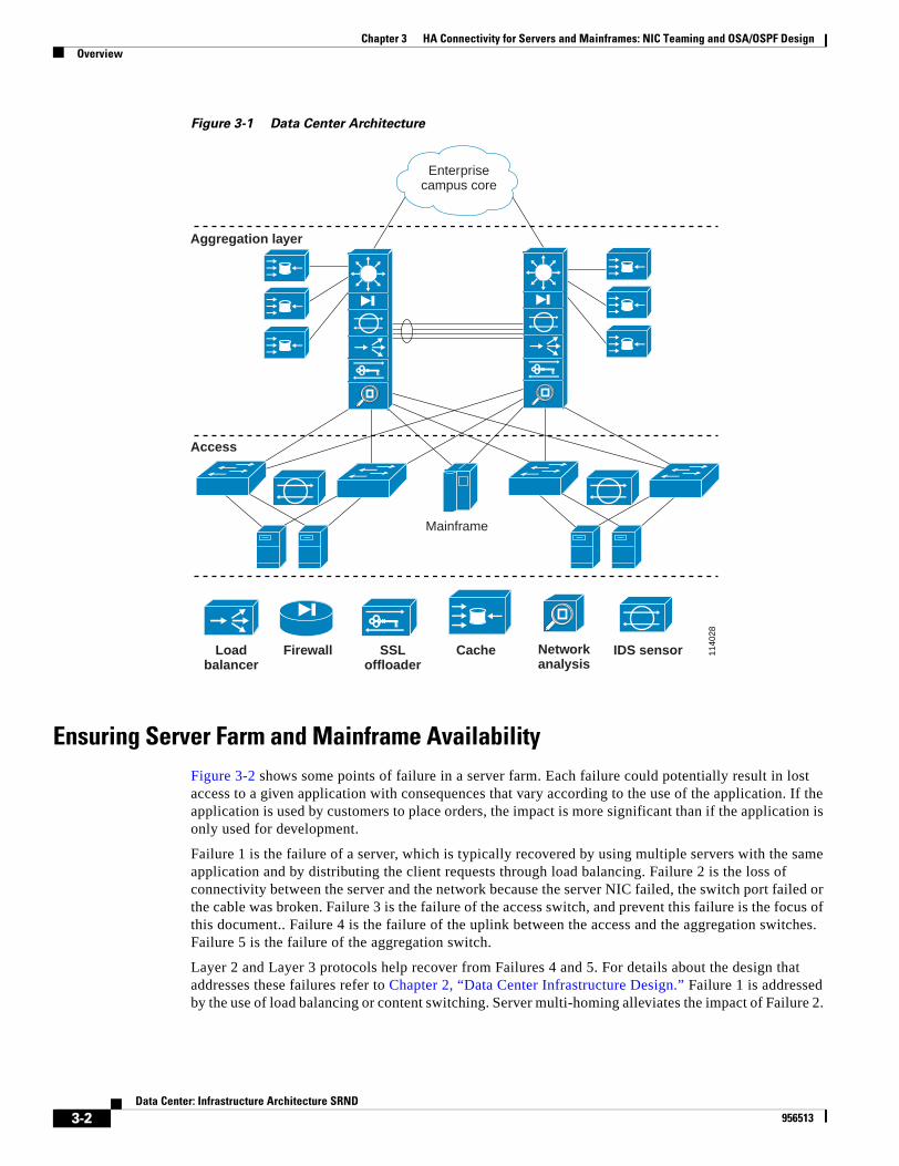
Chapter 3 HA Connectivity for Servers and Mainframes: NIC Teaming and OSA/OSPF DesignOverview
Figure 3-1 Data Center Architecture
Ensuring Server Farm and Mainframe AvailabilityFigure 3-2 shows some points of failure in a server farm. Each failure could potentially result in lost access to a given application with consequences that vary according to the use of the application. If the application is used by customers to place orders, the impact is more significant than if the application is only used for development.
Failure 1 is the failure of a server, which is typically recovered by using multiple servers with the same application and by distributing the client requests through load balancing. Failure 2 is the loss of connectivity between the server and the network because the server NIC failed, the switch port failed or the cable was broken. Failure 3 is the failure of the access switch, and prevent this failure is the focus of this document.. Failure 4 is the failure of the uplink between the access and the aggregation switches. Failure 5 is the failure of the aggregation switch.
Layer 2 and Layer 3 protocols help recover from Failures 4 and 5. For details about the design that addresses these failures refer to Chapter 2, “Data Center Infrastructure Design.” Failure 1 is addressed by the use of load balancing or content switching. Server multi-homing alleviates the impact of Failure 2.
1140
28
Mainframe
Aggregation layer
Access
Loadbalancer
Firewall SSLoffloader
Cache Networkanalysis
IDS sensor
Enterprisecampus core
3-2Data Center: Infrastructure Architecture SRND
956513
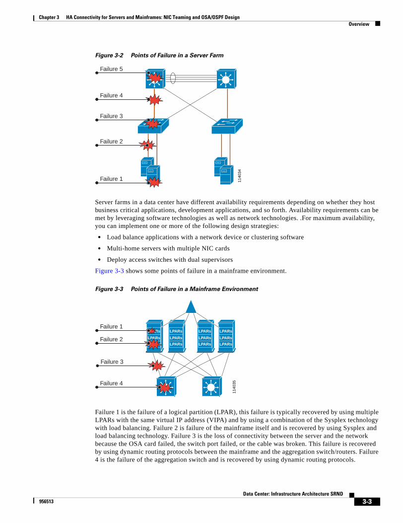
Chapter 3 HA Connectivity for Servers and Mainframes: NIC Teaming and OSA/OSPF DesignOverview
Figure 3-2 Points of Failure in a Server Farm
Server farms in a data center have different availability requirements depending on whether they host business critical applications, development applications, and so forth. Availability requirements can be met by leveraging software technologies as well as network technologies. .For maximum availability, you can implement one or more of the following design strategies:
• Load balance applications with a network device or clustering software
• Multi-home servers with multiple NIC cards
• Deploy access switches with dual supervisors
Figure 3-3 shows some points of failure in a mainframe environment.
Figure 3-3 Points of Failure in a Mainframe Environment
Failure 1 is the failure of a logical partition (LPAR), this failure is typically recovered by using multiple LPARs with the same virtual IP address (VIPA) and by using a combination of the Sysplex technology with load balancing. Failure 2 is failure of the mainframe itself and is recovered by using Sysplex and load balancing technology. Failure 3 is the loss of connectivity between the server and the network because the OSA card failed, the switch port failed, or the cable was broken. This failure is recovered by using dynamic routing protocols between the mainframe and the aggregation switch/routers. Failure 4 is the failure of the aggregation switch and is recovered by using dynamic routing protocols.
1140
34
Failure 5
Failure 4
Failure 3
Failure 2
Failure 1
1140
35
Failure 3
LPARs
LPARs
LPARs
LPARs
LPARs
LPARs
LPARs
LPARs
LPARs
LPARs
LPARs
LPARs
Failure 4
Failure 2
Failure 1
3-3Data Center: Infrastructure Architecture SRND
956513
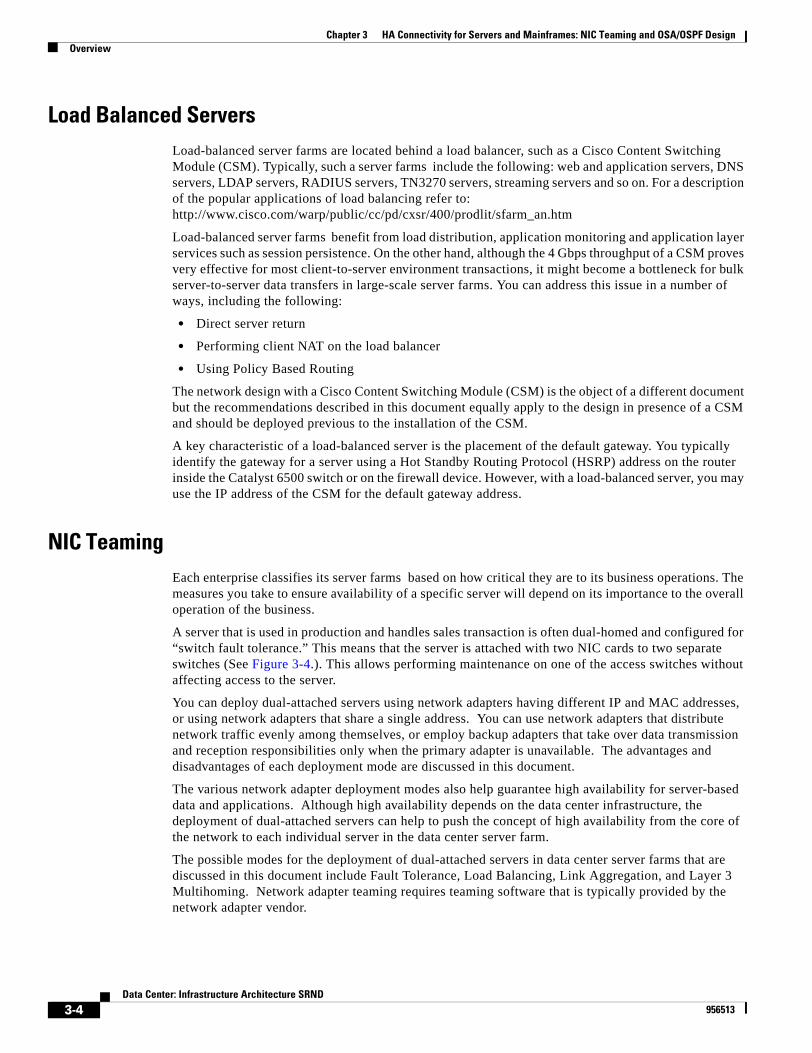
Chapter 3 HA Connectivity for Servers and Mainframes: NIC Teaming and OSA/OSPF DesignOverview
Load Balanced ServersLoad-balanced server farms are located behind a load balancer, such as a Cisco Content Switching Module (CSM). Typically, such a server farms include the following: web and application servers, DNS servers, LDAP servers, RADIUS servers, TN3270 servers, streaming servers and so on. For a description of the popular applications of load balancing refer to: http://www.cisco.com/warp/public/cc/pd/cxsr/400/prodlit/sfarm_an.htm
Load-balanced server farms benefit from load distribution, application monitoring and application layer services such as session persistence. On the other hand, although the 4 Gbps throughput of a CSM proves very effective for most client-to-server environment transactions, it might become a bottleneck for bulk server-to-server data transfers in large-scale server farms. You can address this issue in a number of ways, including the following:
• Direct server return
• Performing client NAT on the load balancer
• Using Policy Based Routing
The network design with a Cisco Content Switching Module (CSM) is the object of a different document but the recommendations described in this document equally apply to the design in presence of a CSM and should be deployed previous to the installation of the CSM.
A key characteristic of a load-balanced server is the placement of the default gateway. You typically identify the gateway for a server using a Hot Standby Routing Protocol (HSRP) address on the router inside the Catalyst 6500 switch or on the firewall device. However, with a load-balanced server, you may use the IP address of the CSM for the default gateway address.
NIC TeamingEach enterprise classifies its server farms based on how critical they are to its business operations. The measures you take to ensure availability of a specific server will depend on its importance to the overall operation of the business.
A server that is used in production and handles sales transaction is often dual-homed and configured for “switch fault tolerance.” This means that the server is attached with two NIC cards to two separate switches (See Figure 3-4.). This allows performing maintenance on one of the access switches without affecting access to the server.
You can deploy dual-attached servers using network adapters having different IP and MAC addresses, or using network adapters that share a single address. You can use network adapters that distribute network traffic evenly among themselves, or employ backup adapters that take over data transmission and reception responsibilities only when the primary adapter is unavailable. The advantages and disadvantages of each deployment mode are discussed in this document.
The various network adapter deployment modes also help guarantee high availability for server-based data and applications. Although high availability depends on the data center infrastructure, the deployment of dual-attached servers can help to push the concept of high availability from the core of the network to each individual server in the data center server farm.
The possible modes for the deployment of dual-attached servers in data center server farms that are discussed in this document include Fault Tolerance, Load Balancing, Link Aggregation, and Layer 3 Multihoming. Network adapter teaming requires teaming software that is typically provided by the network adapter vendor.
3-4Data Center: Infrastructure Architecture SRND
956513
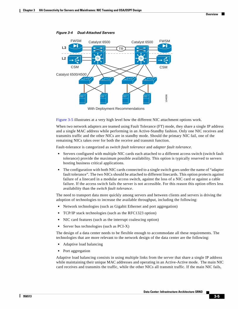
Chapter 3 HA Connectivity for Servers and Mainframes: NIC Teaming and OSA/OSPF DesignOverview
Figure 3-4 Dual-Attached Servers
Figure 3-5 illustrates at a very high level how the different NIC attachment options work.
When two network adapters are teamed using Fault Tolerance (FT) mode, they share a single IP address and a single MAC address while performing in an Active-Standby fashion. Only one NIC receives and transmits traffic and the other NICs are in standby mode. Should the primary NIC fail, one of the remaining NICs takes over for both the receive and transmit function.
Fault-tolerance is categorized as switch fault tolerance and adapter fault tolerance.
• Servers configured with multiple NIC cards each attached to a different access switch (switch fault tolerance) provide the maximum possible availability. This option is typically reserved to servers hosting business critical applications.
• The configuration with both NIC cards connected to a single switch goes under the name of “adapter fault tolerance”. The two NICs should be attached to different linecards. This option protects against failure of a linecard in a modular access switch, against the loss of a NIC card or against a cable failure. If the access switch fails the server is not accessible. For this reason this option offers less availability than the switch fault tolerance.
The need to transport data more quickly among servers and between clients and servers is driving the adoption of technologies to increase the available throughput, including the following:
• Network technologies (such as Gigabit Ethernet and port aggregation)
• TCP/IP stack technologies (such as the RFC1323 option)
• NIC card features (such as the interrupt coalescing option)
• Server bus technologies (such as PCI-X)
The design of a data center needs to be flexible enough to accommodate all these requirements. The technologies that are more relevant to the network design of the data center are the following:
• Adaptive load balancing
• Port aggregation
Adaptive load balancing consists in using multiple links from the server that share a single IP address while maintaining their unique MAC addresses and operating in an Active-Active mode. The main NIC card receives and transmits the traffic, while the other NICs all transmit traffic. If the main NIC fails,
1040
06
With Deployment Recommendations
Si Si
TR
FWSM
CSM
Catalyst 6500 FWSM
CSM
Catalyst 6500/4500
Catalyst 6500
L2
L3
3-5Data Center: Infrastructure Architecture SRND
956513
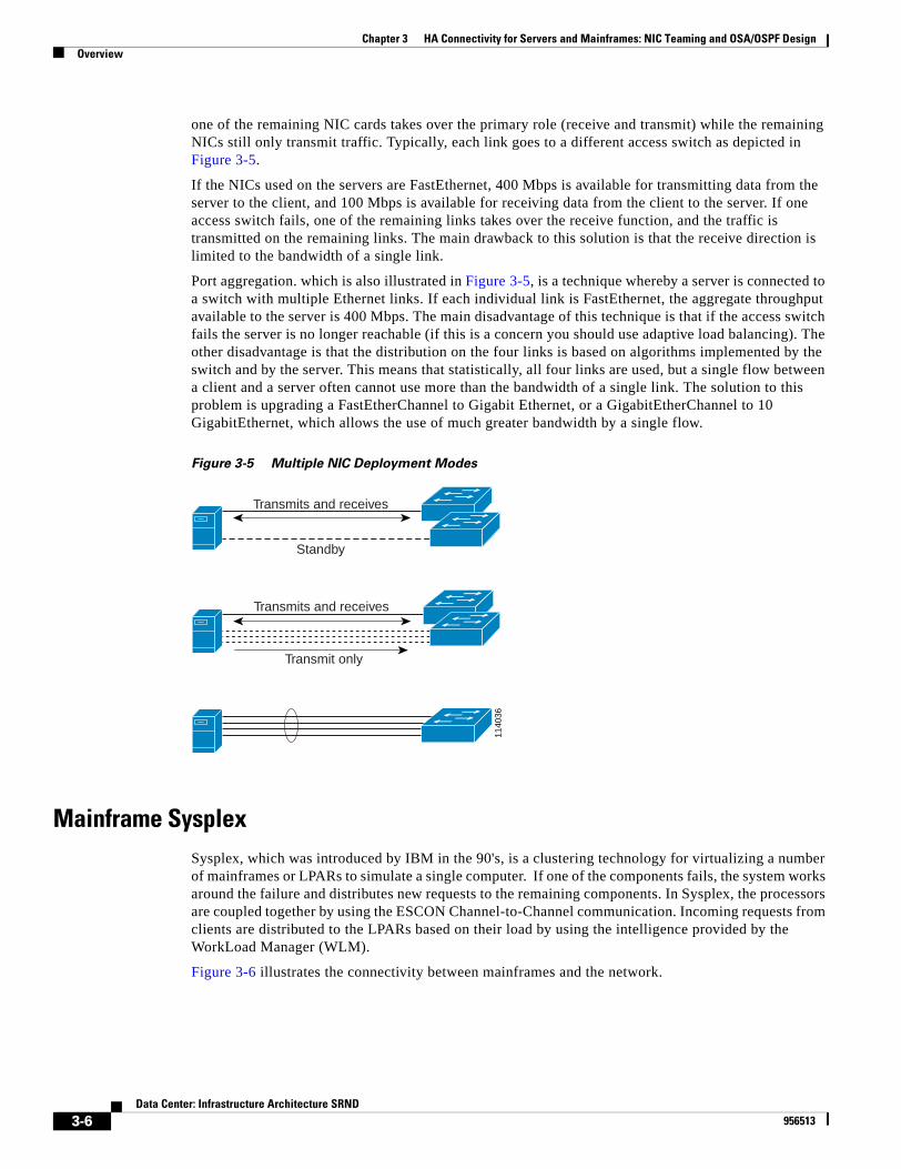
Chapter 3 HA Connectivity for Servers and Mainframes: NIC Teaming and OSA/OSPF DesignOverview
one of the remaining NIC cards takes over the primary role (receive and transmit) while the remaining NICs still only transmit traffic. Typically, each link goes to a different access switch as depicted in Figure 3-5.
If the NICs used on the servers are FastEthernet, 400 Mbps is available for transmitting data from the server to the client, and 100 Mbps is available for receiving data from the client to the server. If one access switch fails, one of the remaining links takes over the receive function, and the traffic is transmitted on the remaining links. The main drawback to this solution is that the receive direction is limited to the bandwidth of a single link.
Port aggregation. which is also illustrated in Figure 3-5, is a technique whereby a server is connected to a switch with multiple Ethernet links. If each individual link is FastEthernet, the aggregate throughput available to the server is 400 Mbps. The main disadvantage of this technique is that if the access switch fails the server is no longer reachable (if this is a concern you should use adaptive load balancing). The other disadvantage is that the distribution on the four links is based on algorithms implemented by the switch and by the server. This means that statistically, all four links are used, but a single flow between a client and a server often cannot use more than the bandwidth of a single link. The solution to this problem is upgrading a FastEtherChannel to Gigabit Ethernet, or a GigabitEtherChannel to 10 GigabitEthernet, which allows the use of much greater bandwidth by a single flow.
Figure 3-5 Multiple NIC Deployment Modes
Mainframe SysplexSysplex, which was introduced by IBM in the 90's, is a clustering technology for virtualizing a number of mainframes or LPARs to simulate a single computer. If one of the components fails, the system works around the failure and distributes new requests to the remaining components. In Sysplex, the processors are coupled together by using the ESCON Channel-to-Channel communication. Incoming requests from clients are distributed to the LPARs based on their load by using the intelligence provided by the WorkLoad Manager (WLM).
Figure 3-6 illustrates the connectivity between mainframes and the network.
1140
36Transmits and receives
Standby
Transmit only
Transmits and receives
3-6Data Center: Infrastructure Architecture SRND
956513
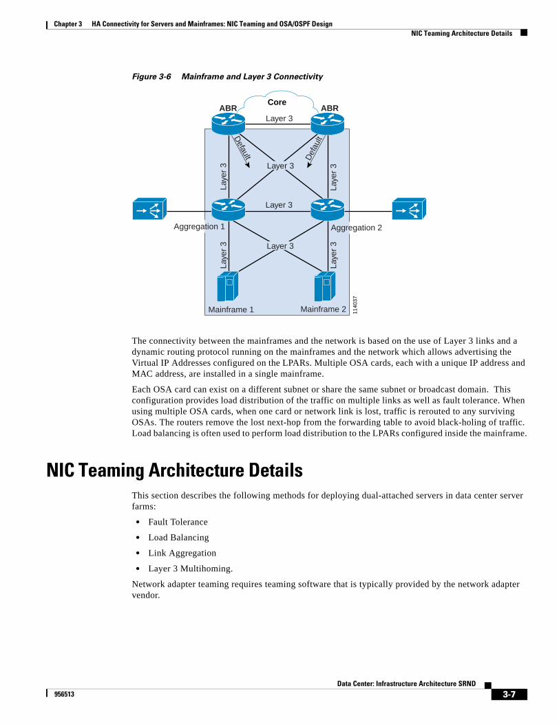
Chapter 3 HA Connectivity for Servers and Mainframes: NIC Teaming and OSA/OSPF DesignNIC Teaming Architecture Details
Figure 3-6 Mainframe and Layer 3 Connectivity
The connectivity between the mainframes and the network is based on the use of Layer 3 links and a dynamic routing protocol running on the mainframes and the network which allows advertising the Virtual IP Addresses configured on the LPARs. Multiple OSA cards, each with a unique IP address and MAC address, are installed in a single mainframe.
Each OSA card can exist on a different subnet or share the same subnet or broadcast domain. This configuration provides load distribution of the traffic on multiple links as well as fault tolerance. When using multiple OSA cards, when one card or network link is lost, traffic is rerouted to any surviving OSAs. The routers remove the lost next-hop from the forwarding table to avoid black-holing of traffic. Load balancing is often used to perform load distribution to the LPARs configured inside the mainframe.
NIC Teaming Architecture DetailsThis section describes the following methods for deploying dual-attached servers in data center server farms:
• Fault Tolerance
• Load Balancing
• Link Aggregation
• Layer 3 Multihoming.
Network adapter teaming requires teaming software that is typically provided by the network adapter vendor.
Core
1140
37
ABRABR
Default D
efau
lt
Layer 3
Laye
r 3
Laye
r 3
Laye
r 3
Laye
r 3
Layer 3
Layer 3
Layer 3
Mainframe 1
Aggregation 1
Mainframe 2
Aggregation 2
3-7Data Center: Infrastructure Architecture SRND
956513

Chapter 3 HA Connectivity for Servers and Mainframes: NIC Teaming and OSA/OSPF DesignNIC Teaming Architecture Details
Hardware and SoftwareThe deployment modes described in this document have been tested using the following operating systems:
• Microsoft Windows 2000, Windows Server 2003, and Windows NT 4
• NetWare 4.11 and above, UnixWare* 7.x with ddi8
• Linux (32 bit).
The recommended deployment modes are compatible with most network adapters, including products from HP-Compaq, Broadcom, and Intel.
We do not recommend the use of dynamically assigned IP addresses (DHCP) for server configuration in conjunction with any of these deployment modes. Also, proper implementation of the suggested dual-attached server deployment modes requires that all network adapters belong to the same VLAN.
The recommendations made in this document are based upon testing performed with the Intel PRO/1000 MT Server adapter configured as shown in Table 3-1.
For more relevant deployment-related information, please refer to the network adapter and teaming documentation provided by your preferred vendor.
Deployment Modes
This section describes the different deployment modes available for configuring dual-attached servers and it includes the following topics:
• Fault Tolerance Modes
• Load Balancing Modes
• Link Aggregation Modes
• Layer 3 Multihoming
Fault Tolerance Modes
This section describes the different fault tolerance modes and it includes the following topics:• Overview
• Adapter Fault Tolerance
• Switch Fault Tolerance
Table 3-1 Tested Dual Attached Server Configurations
Microsoft Windows 2000 Server Red Hat Linux 9.0
Intel PROSet Software Ver. 8.2.0 Ver. 1.7.68 (PROcfg daemon)Ver. 1.7.64 (PROcfg config tool)
Network Adapter Driver Ver. 7.2.17 (bundled with PROSet 8.2.0 software)
Ver. 5.2.16
Advanced Networking Services (ANS) Adapter
Ver. 6.24.0 (bundled with PROSet) 8.2.0 software)
Ver. 2.3.61
3-8Data Center: Infrastructure Architecture SRND
956513
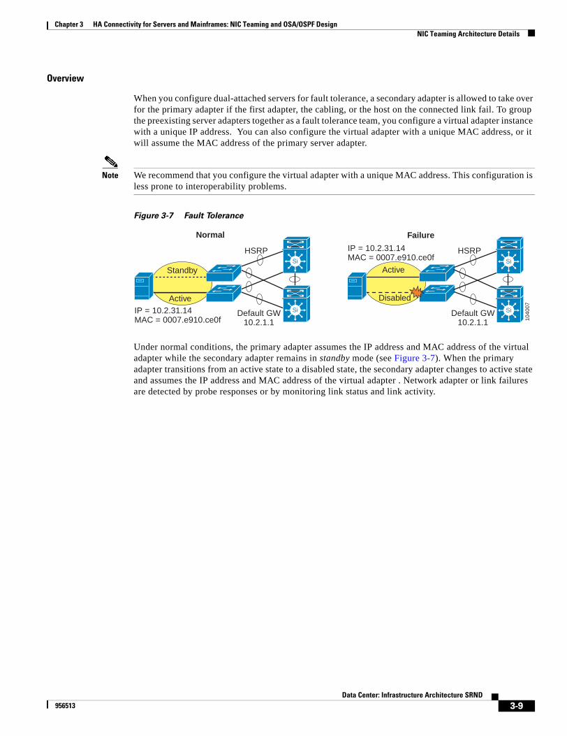
Chapter 3 HA Connectivity for Servers and Mainframes: NIC Teaming and OSA/OSPF DesignNIC Teaming Architecture Details
Overview
When you configure dual-attached servers for fault tolerance, a secondary adapter is allowed to take over for the primary adapter if the first adapter, the cabling, or the host on the connected link fail. To group the preexisting server adapters together as a fault tolerance team, you configure a virtual adapter instance with a unique IP address. You can also configure the virtual adapter with a unique MAC address, or it will assume the MAC address of the primary server adapter.
Note We recommend that you configure the virtual adapter with a unique MAC address. This configuration is less prone to interoperability problems.
Figure 3-7 Fault Tolerance
Under normal conditions, the primary adapter assumes the IP address and MAC address of the virtual adapter while the secondary adapter remains in standby mode (see Figure 3-7). When the primary adapter transitions from an active state to a disabled state, the secondary adapter changes to active state and assumes the IP address and MAC address of the virtual adapter . Network adapter or link failures are detected by probe responses or by monitoring link status and link activity.
HSRP
Standby
Active
Normal Failure
Si
SiDefault GW10.2.1.1
IP = 10.2.31.14MAC = 0007.e910.ce0f
HSRP
Disabled
Active
Default GW10.2.1.1
IP = 10.2.31.14MAC = 0007.e910.ce0f Si
Si
1040
07
3-9Data Center: Infrastructure Architecture SRND
956513
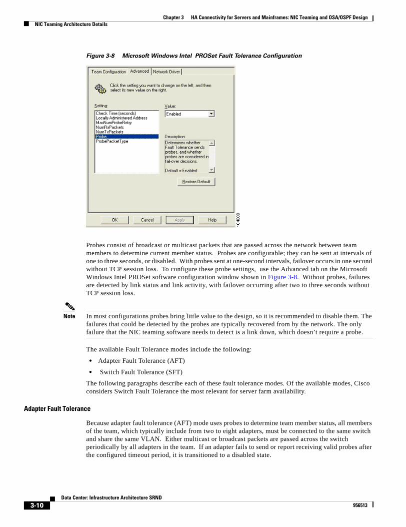
Chapter 3 HA Connectivity for Servers and Mainframes: NIC Teaming and OSA/OSPF DesignNIC Teaming Architecture Details
Figure 3-8 Microsoft Windows Intel PROSet Fault Tolerance Configuration
Probes consist of broadcast or multicast packets that are passed across the network between team members to determine current member status. Probes are configurable; they can be sent at intervals of one to three seconds, or disabled. With probes sent at one-second intervals, failover occurs in one second without TCP session loss. To configure these probe settings, use the Advanced tab on the Microsoft Windows Intel PROSet software configuration window shown in Figure 3-8. Without probes, failures are detected by link status and link activity, with failover occurring after two to three seconds without TCP session loss.
Note In most configurations probes bring little value to the design, so it is recommended to disable them. The failures that could be detected by the probes are typically recovered from by the network. The only failure that the NIC teaming software needs to detect is a link down, which doesn’t require a probe.
The available Fault Tolerance modes include the following:
• Adapter Fault Tolerance (AFT)
• Switch Fault Tolerance (SFT)
The following paragraphs describe each of these fault tolerance modes. Of the available modes, Cisco considers Switch Fault Tolerance the most relevant for server farm availability.
Adapter Fault Tolerance
Because adapter fault tolerance (AFT) mode uses probes to determine team member status, all members of the team, which typically include from two to eight adapters, must be connected to the same switch and share the same VLAN. Either multicast or broadcast packets are passed across the switch periodically by all adapters in the team. If an adapter fails to send or report receiving valid probes after the configured timeout period, it is transitioned to a disabled state.
3-10Data Center: Infrastructure Architecture SRND
956513
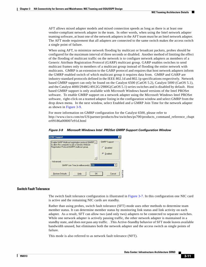
Chapter 3 HA Connectivity for Servers and Mainframes: NIC Teaming and OSA/OSPF DesignNIC Teaming Architecture Details
AFT allows mixed adapter models and mixed connection speeds as long as there is at least one vendor-compliant network adapter in the team. In other words, when using the Intel network adapter teaming software, at least one of the network adapters in the AFT team must be an Intel network adapter. The AFT mode requirement that all adapters are connected to the same switch makes the access switch a single point of failure.
When using AFT, to minimize network flooding by multicast or broadcast packets, probes should be configured for the maximum interval of three seconds or disabled. Another method of limiting the effect of the flooding of multicast traffic on the network is to configure network adapters as members of a Generic Attribute Registration Protocol (GARP) multicast group. GARP enables switches to send multicast frames only to members of a multicast group instead of flooding the entire network with multicasts. GMRP is an extension to the GARP protocol and requires that host network adapters inform the GMRP enabled switch of which multicast group it requires data from. GMRP and GARP are industry-standard protocols defined in the IEEE 802.1d and 802.1p specifications respectively. Network based GMRP support can only be found on the Catalyst 6500 (CatOS 5.2), Catalyst 5000 (CatOS 5.1), and the Catalyst 4000/2948G/4912G/2980G(CatOS 5.1) series switches and is disabled by default. Host based GMRP support is only available with Microsoft Windows based versions of the Intel PROSet software. To enable GMRP support on a network adapter using the Microsoft Windows Intel PROSet software, right-click on a teamed adapter listing in the configuration window and select GMRP from the drop down menu. In the next window, select Enabled and a GMRP Join Time for the network adapter as shown in Figure 3-9.
For more information on GMRP configuration for the Catalyst 6500, please refer to http://www.cisco.com/en/US/partner/products/hw/switches/ps700/products_command_reference_chapter09186a008007e91d.html
Figure 3-9 Microsoft Windows Intel PROSet GMRP Support Configuration Window
Switch Fault Tolerance
The switch fault tolerance configuration is illustrated in Figure 3-7. In this configuration one NIC card is active and the remaining NIC cards are standby.
Rather than using probes, switch fault tolerance (SFT) mode uses other methods to determine team member status. It can determine member status by monitoring link status and link activity on each adapter. As a result, SFT can allow two (and only two) adapters to be connected to separate switches. While one network adapter is actively passing traffic, the other network adapter is maintained in a standby state, and does not pass any traffic. .This Active-Standby behavior of SFT mode leaves available bandwidth unused, but eliminates both the network adapter and the access switch as single points of failure.
This mode is also referred to as network fault tolerance (NFT).
3-11Data Center: Infrastructure Architecture SRND
956513
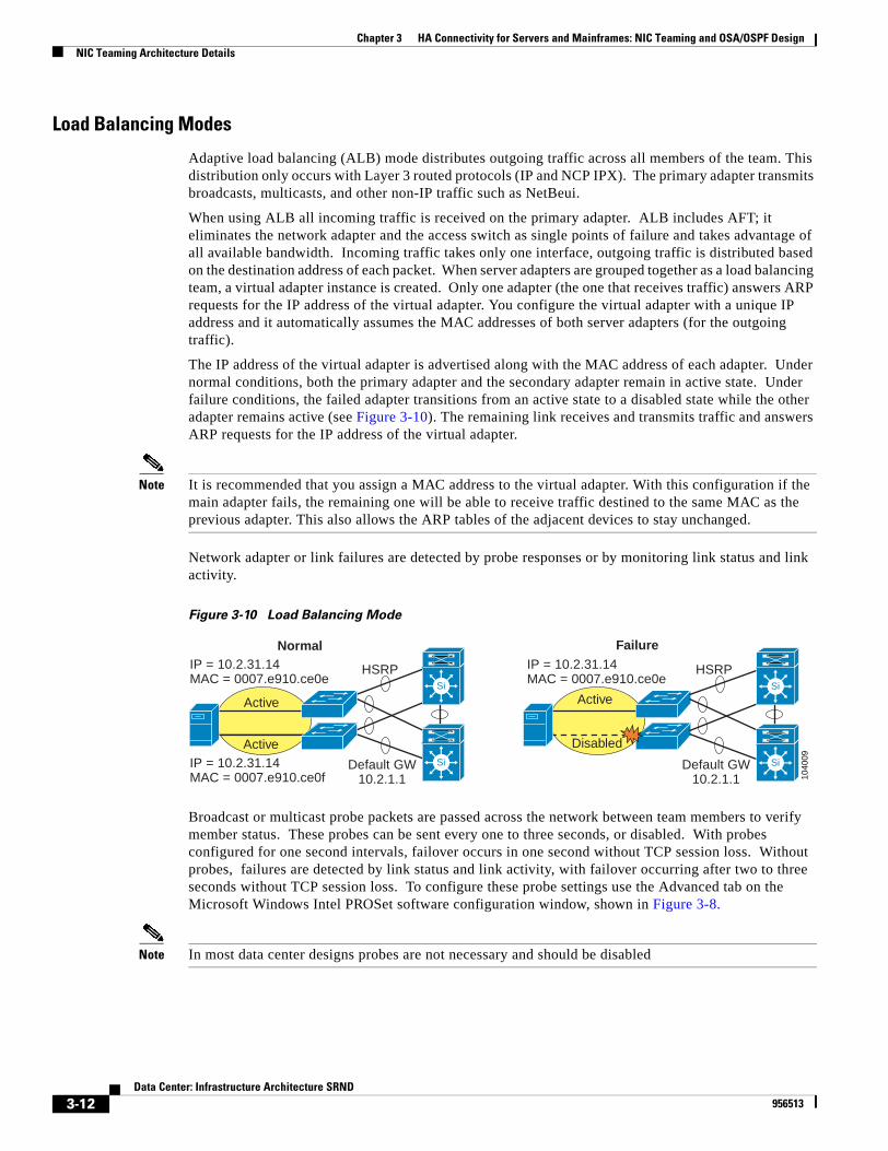
Chapter 3 HA Connectivity for Servers and Mainframes: NIC Teaming and OSA/OSPF DesignNIC Teaming Architecture Details
Load Balancing Modes
Adaptive load balancing (ALB) mode distributes outgoing traffic across all members of the team. This distribution only occurs with Layer 3 routed protocols (IP and NCP IPX). The primary adapter transmits broadcasts, multicasts, and other non-IP traffic such as NetBeui.
When using ALB all incoming traffic is received on the primary adapter. ALB includes AFT; it eliminates the network adapter and the access switch as single points of failure and takes advantage of all available bandwidth. Incoming traffic takes only one interface, outgoing traffic is distributed based on the destination address of each packet. When server adapters are grouped together as a load balancing team, a virtual adapter instance is created. Only one adapter (the one that receives traffic) answers ARP requests for the IP address of the virtual adapter. You configure the virtual adapter with a unique IP address and it automatically assumes the MAC addresses of both server adapters (for the outgoing traffic).
The IP address of the virtual adapter is advertised along with the MAC address of each adapter. Under normal conditions, both the primary adapter and the secondary adapter remain in active state. Under failure conditions, the failed adapter transitions from an active state to a disabled state while the other adapter remains active (see Figure 3-10). The remaining link receives and transmits traffic and answers ARP requests for the IP address of the virtual adapter.
Note It is recommended that you assign a MAC address to the virtual adapter. With this configuration if the main adapter fails, the remaining one will be able to receive traffic destined to the same MAC as the previous adapter. This also allows the ARP tables of the adjacent devices to stay unchanged.
Network adapter or link failures are detected by probe responses or by monitoring link status and link activity.
Figure 3-10 Load Balancing Mode
Broadcast or multicast probe packets are passed across the network between team members to verify member status. These probes can be sent every one to three seconds, or disabled. With probes configured for one second intervals, failover occurs in one second without TCP session loss. Without probes, failures are detected by link status and link activity, with failover occurring after two to three seconds without TCP session loss. To configure these probe settings use the Advanced tab on the Microsoft Windows Intel PROSet software configuration window, shown in Figure 3-8.
Note In most data center designs probes are not necessary and should be disabled
1040
09
Normal Failure
Default GW10.2.1.1
IP = 10.2.31.14MAC = 0007.e910.ce0f
Default GW10.2.1.1
IP = 10.2.31.14MAC = 0007.e910.ce0e
HSRP
Active
Si
Si
HSRP
Disabled
ActiveSi
Si
IP = 10.2.31.14MAC = 0007.e910.ce0e
Active
3-12Data Center: Infrastructure Architecture SRND
956513
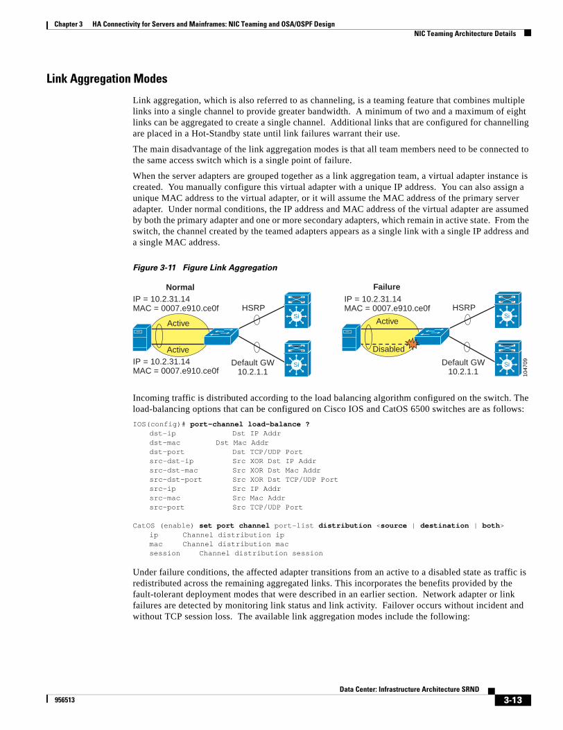
Chapter 3 HA Connectivity for Servers and Mainframes: NIC Teaming and OSA/OSPF DesignNIC Teaming Architecture Details
Link Aggregation Modes
Link aggregation, which is also referred to as channeling, is a teaming feature that combines multiple links into a single channel to provide greater bandwidth. A minimum of two and a maximum of eight links can be aggregated to create a single channel. Additional links that are configured for channelling are placed in a Hot-Standby state until link failures warrant their use.
The main disadvantage of the link aggregation modes is that all team members need to be connected to the same access switch which is a single point of failure.
When the server adapters are grouped together as a link aggregation team, a virtual adapter instance is created. You manually configure this virtual adapter with a unique IP address. You can also assign a unique MAC address to the virtual adapter, or it will assume the MAC address of the primary server adapter. Under normal conditions, the IP address and MAC address of the virtual adapter are assumed by both the primary adapter and one or more secondary adapters, which remain in active state. From the switch, the channel created by the teamed adapters appears as a single link with a single IP address and a single MAC address.
Figure 3-11 Figure Link Aggregation
Incoming traffic is distributed according to the load balancing algorithm configured on the switch. The load-balancing options that can be configured on Cisco IOS and CatOS 6500 switches are as follows:
IOS(config)# port-channel load-balance ? dst-ip Dst IP Addr dst-mac Dst Mac Addr dst-port Dst TCP/UDP Port src-dst-ip Src XOR Dst IP Addr src-dst-mac Src XOR Dst Mac Addr src-dst-port Src XOR Dst TCP/UDP Port src-ip Src IP Addr src-mac Src Mac Addr src-port Src TCP/UDP Port
CatOS (enable) set port channel port-list distribution <source | destination | both>ip Channel distribution ipmac Channel distribution macsession Channel distribution session
Under failure conditions, the affected adapter transitions from an active to a disabled state as traffic is redistributed across the remaining aggregated links. This incorporates the benefits provided by the fault-tolerant deployment modes that were described in an earlier section. Network adapter or link failures are detected by monitoring link status and link activity. Failover occurs without incident and without TCP session loss. The available link aggregation modes include the following:
1047
09
Normal Failure
Default GW10.2.1.1
IP = 10.2.31.14MAC = 0007.e910.ce0f
IP = 10.2.31.14MAC = 0007.e910.ce0f HSRP
Active
Si
Si
Disabled
Active
IP = 10.2.31.14MAC = 0007.e910.ce0f
Active
Default GW10.2.1.1
HSRPSi
Si
3-13Data Center: Infrastructure Architecture SRND
956513

Chapter 3 HA Connectivity for Servers and Mainframes: NIC Teaming and OSA/OSPF DesignNIC Teaming Architecture Details
• Fast EtherChannel (FEC): Fast EtherChannel mode creates a channel using Fast Ethernet (100 Mb) links. EtherChannel is a Cisco-proprietary method for channeling, and requires Cisco EtherChannel-capable switches. Port Aggregation Protocol (PAgP) is another Cisco proprietary protocol that helps create EtherChannel links automatically. PAgP packets are sent between EtherChannel-capable ports to negotiate the formation of a channel.
• Gigabit EtherChannel (GEC): Gigabit EtherChannel mode creates a channel using Gigabit Ethernet (1000 Mb) links. Once again, Cisco EtherChannel-capable switches are required for this mode.
• IEEE 802.3ad (LACP): IEEE 802.3ad mode creates channels using Fast Ethernet (100 Mb) or Gigabit Ethernet (1000 Mb) links. IEEE 802.3ad, which is also know as Link Aggregation Control Protocol (LACP), is an IEEE specification that is very similar to the Cisco implementation of EtherChannel. However, it uses LACP packets instead of PAgP packets to negotiate the formation of a channel. Also LACP does not support half-duplex ports, while EtherChannel does. The main advantage of LACP interoperability with switches from different vendors. LACP is available with the following Cisco platforms and versions.
Support for 802.3ad (LACP) was introduced on the Cisco switches in the following software releases:
• Catalyst 6000/6500 Series with CatOS Version 7.1(1) and later
• Catalyst 6000/6500 Series with Cisco IOS Version 12.1(11b)EX and later
• Catalyst 4000/4500 Series with CatOS Version 7.1(1) and later
• Catalyst 4000/4500 Series with Cisco IOS Version 12.1(13)EW and later
You can implement LACP in either static or dynamic mode. Static mode is supported by the majority of switches on the market. LACP channeling, like EtherChannel, must be explicitly configured on both of the partnered devices.
Dynamic mode requires the use of 802.3ad Dynamic-capable switches, which are limited in availability. 802.3ad dynamic mode automatically detects LACP-capable ports and creates and configures a port channel using the associated links. Dynamic mode LACP can be configured as follows.
IOS(config)# interface type slot/portIOS(config-if)# switchportIOS(config-if)# channel-protocol lacpIOS(config-if)# channel-group 1-256 mode activeIOS(config-if)# show etherchannel port-channel
CatOS(enable) set channelprotocol lacp slotCatOS(enable) set port lacp-channel mod/ports_listCatOS(enable) set port lacp-channel mod/ports_list mode activeCatOS(enable) show port lacp-channel
For more information on LACP, PAgP, and configuring Etherchannels, see: http://www.cisco.com/univercd/cc/td/doc/product/lan/cat6000/12_1e/swconfig/channel.htm
Layer 3 Multihoming
With Layer 3 multihoming, multiple network adapters are installed in a single server. Each network adapter has a unique IP address and MAC address and they can exist on different subnets or share the same subnet or broadcast domain. As with the adapter teaming modes described earlier, fault tolerance and load balancing are the primary goals, but Layer 3 multihoming does not the use a virtual network adapter. When using multiple adapters with Layer 3 multihoming, when one adapter or network link is lost, traffic is rerouted to one or more surviving adapters. Also, network traffic can be shared across the multiple adapters. An important property of a fault tolerant solution is that TCP connections survive failures transparently and completely.
3-14Data Center: Infrastructure Architecture SRND
956513

Chapter 3 HA Connectivity for Servers and Mainframes: NIC Teaming and OSA/OSPF DesignNIC Teaming Architecture Details
How Servers Route Traffic
Unfortunately, deploying Layer 3 multihomed servers may be more difficult than it sounds. Deploying multihomed servers creates unique challenges, which must be solved at different levels, from the application or Application Programming Interface (API) down to the TCP/IP stack. The required solutions and workarounds can create confusion and scalability issues.
When an IP datagram is sent from a multihomed host, the host passes the datagram to the interface with the best apparent route to the destination. Accordingly, the datagram may contain the source IP address of one interface in the multihomed host, but be placed on the media by a different interface. The source MAC address on the frame is that of the interface that actually transmits the frame to the media, while the source IP address is provided by the application.
To prevent routing problems when configuring a computer to be multihomed on two disjoint networks (networks that are separate from and unaware of each other), configure the default gateway on the network adapter attached to the network that contains the most subnets (typically the Internet). You can use either static routes or a dynamic routing protocol to provide connectivity to the subnets reachable from the other network adapter (typically your intranet). Configuring a different default gateway on each side can result in unpredictable behavior and loss of connectivity. You should keep in mind that only one default gateway can be active for a computer at any given moment.
In earlier versions of Windows, if multiple default routes exist in the IP routing table (assuming a metric of 1), the specific default route was chosen randomly when TCP/IP was initialized. This behavior often led to confusion and loss of connectivity. Newer versions of Microsoft Windows provides two options. One option automatically determines a routing metric, indicating the cost of the route based on the speed of the interface. The other option is the traditional one, which allows you to enter a static, interface-based metric. Although you can configure a different default gateway for each adapter, Windows uses only one default gateway at a time. This means that only certain hosts will be reachable.
You can also run dynamic routing protocols on Linux and Unix-based platforms. To run dynamic routing protocols, you must load routing protocol management software, which is freely available, onto the server. Two of the more popular routing protocol management software programs for Linux include Zebra and GateD. Zebra supports BGP-4, BGP-4+, RIPv1/v2, RIPng, OSPFv2 and OSPFv3. GateD supports BGP, IS-IS, RIPv1/v2, OSPFv2 and OSPFv3. For more information about these software programs, see http://www.zebra.org or http://www.gated.org
Interactions with DNS
With a multihomed server, Domain Name System (DNS) configuration settings are global, unless otherwise noted. To provide a unique DNS configuration for each network adapter on a Windows server, enter a DNS suffix in the appropriate text box on the DNS tab in the Advanced TCP/IP Properties dialog box. Windows Internet Name Service (WINS) configuration settings are defined for each adapter. The settings on the WINS configuration tab are only applied to the selected adapter.
On a server with two or more NICs, WINS registers the last interface card installed on the server as its primary entry. When a client performs a NetBIOS name query request to WINS, it receives a list of all IP addresses for that server. The IP addresses are listed with the most recently installed adapter first and the client uses the addresses in the order in which they are listed. This is significant because using the wrong IP address for a server can cause unpredictable behavior or loss of connectivity. To change the order in which the IP addresses are registered in WINS you must remove and reregistering the adapters with WINS, or statically register the entries. Static registration may be tedious because it involves manually entering IP and NetBIOS names.
Static and Dynamic Routing Configuration on Windows
To add static routes on a Windows-based server use the following command:
3-15Data Center: Infrastructure Architecture SRND
956513

Chapter 3 HA Connectivity for Servers and Mainframes: NIC Teaming and OSA/OSPF DesignNIC Teaming Architecture Details
C:\>route ADD [ destination ] [ MASK netmask ] [ gateway ] [ METRIC metric ] [ IF interface ]
For example:
C:\>route ADD 157.0.0.0 MASK 255.0.0.0 157.55.80.1 METRIC 3 IF 2
For more information about this command, type route help from the MS DOS command prompt.
To add static routes on Linux-based servers, use the following command:
# route add [ destination ] [ gateway ]
For example:
# route add 157.0.0.0 157.55.80.1
For more information about this command, type man route from the Linux command prompt.
You can configure Microsoft Windows to run dynamic routing protocols, specifically RIPv2 and OSPF. By default, IP routing, (also referred to as TCP/IP forwarding), is disabled. To enable IP routing, you must allow the computer to forward any IP packets it receives. This requires a change to the Windows 2000 system registry. When you enable the Routing and Remote Access service for IP routing, the registry entry is made automatically. To enable IP routing, perform the following steps:
Step 1 Click Start > Programs > Administrative Tools > Routing and Remote Access or Services.
Step 2 On the Action menu, click Configure and Enable Routing and Remote Access, and complete the wizard.
Step 3 Right-click the server for which you want to enable routing, and then click Properties.
Step 4 On the General tab, click to select the Router check box.
Step 5 Click Local Area network (LAN) routing only, and click OK.
These instructions for enabling IP routing are specific to Windows 2000 Server and Windows 2003 Server. For instructions for other versions of Microsoft Windows, please see the Microsoft Knowledge Base located at http://support.microsoft.com.
Interoperability with SecurityThe availability of the computing resources housed in data centers is critical to the everyday operations of an enterprise. This could be greatly affected by malicious attacks on these resources, such as denial of services attacks, network reconnaissance, viruses and worms, IP spoofing, and other Layer 2 attacks. Security recommendations have been made in order to prevent attackers from gaining unauthorized access to these resources which could result in unnecessary downtime for the data center.
Deploying dual-attached servers in a server farm poses some challenges because of the interaction with security tools that are commonly deployed in a server farm and under certain circumstances can cause either false alarms or could make certain security measures ineffective. Following the design recommendations in this section makes it possible to take advantage of the higher availability delivered by the dual attachment configuration without giving up security in the server farm.
3-16Data Center: Infrastructure Architecture SRND
956513
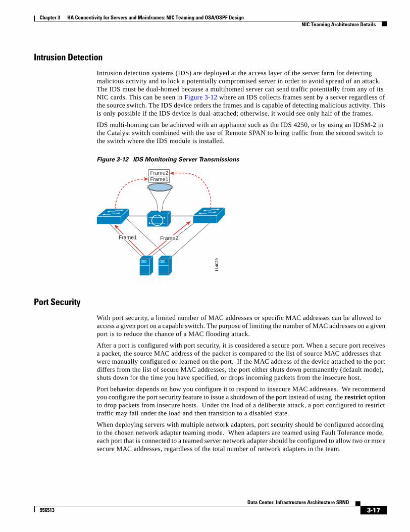
Chapter 3 HA Connectivity for Servers and Mainframes: NIC Teaming and OSA/OSPF DesignNIC Teaming Architecture Details
Intrusion Detection
Intrusion detection systems (IDS) are deployed at the access layer of the server farm for detecting malicious activity and to lock a potentially compromised server in order to avoid spread of an attack. The IDS must be dual-homed because a multihomed server can send traffic potentially from any of its NIC cards. This can be seen in Figure 3-12 where an IDS collects frames sent by a server regardless of the source switch. The IDS device orders the frames and is capable of detecting malicious activity. This is only possible if the IDS device is dual-attached; otherwise, it would see only half of the frames.
IDS multi-homing can be achieved with an appliance such as the IDS 4250, or by using an IDSM-2 in the Catalyst switch combined with the use of Remote SPAN to bring traffic from the second switch to the switch where the IDS module is installed.
Figure 3-12 IDS Monitoring Server Transmissions
Port Security
With port security, a limited number of MAC addresses or specific MAC addresses can be allowed to access a given port on a capable switch. The purpose of limiting the number of MAC addresses on a given port is to reduce the chance of a MAC flooding attack.
After a port is configured with port security, it is considered a secure port. When a secure port receives a packet, the source MAC address of the packet is compared to the list of source MAC addresses that were manually configured or learned on the port. If the MAC address of the device attached to the port differs from the list of secure MAC addresses, the port either shuts down permanently (default mode), shuts down for the time you have specified, or drops incoming packets from the insecure host.
Port behavior depends on how you configure it to respond to insecure MAC addresses. We recommend you configure the port security feature to issue a shutdown of the port instead of using the restrict option to drop packets from insecure hosts. Under the load of a deliberate attack, a port configured to restrict traffic may fail under the load and then transition to a disabled state.
When deploying servers with multiple network adapters, port security should be configured according to the chosen network adapter teaming mode. When adapters are teamed using Fault Tolerance mode, each port that is connected to a teamed server network adapter should be configured to allow two or more secure MAC addresses, regardless of the total number of network adapters in the team.
1140
39
Frame2Frame1
Frame1 Frame2
3-17Data Center: Infrastructure Architecture SRND
956513
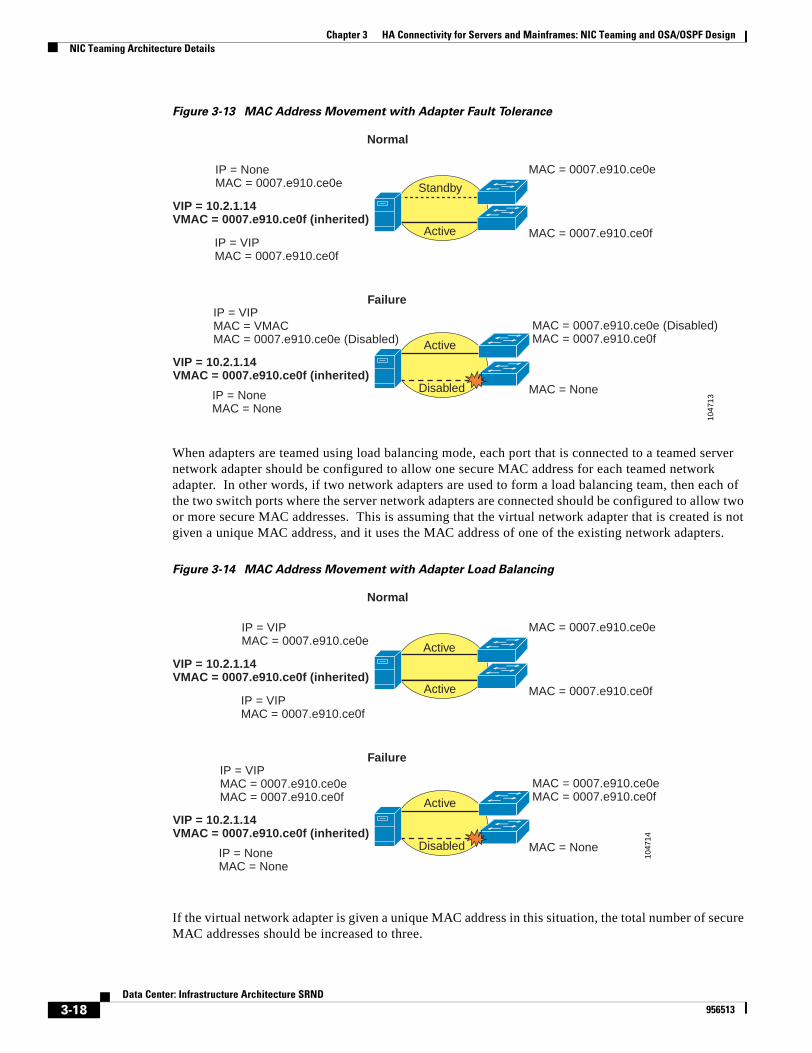
Chapter 3 HA Connectivity for Servers and Mainframes: NIC Teaming and OSA/OSPF DesignNIC Teaming Architecture Details
Figure 3-13 MAC Address Movement with Adapter Fault Tolerance
When adapters are teamed using load balancing mode, each port that is connected to a teamed server network adapter should be configured to allow one secure MAC address for each teamed network adapter. In other words, if two network adapters are used to form a load balancing team, then each of the two switch ports where the server network adapters are connected should be configured to allow two or more secure MAC addresses. This is assuming that the virtual network adapter that is created is not given a unique MAC address, and it uses the MAC address of one of the existing network adapters.
Figure 3-14 MAC Address Movement with Adapter Load Balancing
If the virtual network adapter is given a unique MAC address in this situation, the total number of secure MAC addresses should be increased to three.
1047
13
Normal
Failure
IP = NoneMAC = 0007.e910.ce0e
IP = VIPMAC = 0007.e910.ce0f
Active
Disabled
Active
Standby
VIP = 10.2.1.14VMAC = 0007.e910.ce0f (inherited)
MAC = 0007.e910.ce0e
MAC = 0007.e910.ce0f
IP = VIPMAC = VMACMAC = 0007.e910.ce0e (Disabled)
IP = NoneMAC = None
VIP = 10.2.1.14VMAC = 0007.e910.ce0f (inherited)
MAC = 0007.e910.ce0e (Disabled)MAC = 0007.e910.ce0f
MAC = None
1047
14
Normal
Failure
IP = VIPMAC = 0007.e910.ce0e
IP = VIPMAC = 0007.e910.ce0f
Active
Disabled
Active
VIP = 10.2.1.14VMAC = 0007.e910.ce0f (inherited)
MAC = 0007.e910.ce0e
MAC = 0007.e910.ce0f
IP = VIPMAC = 0007.e910.ce0eMAC = 0007.e910.ce0f
IP = NoneMAC = None
VIP = 10.2.1.14VMAC = 0007.e910.ce0f (inherited)
MAC = 0007.e910.ce0eMAC = 0007.e910.ce0f
MAC = None
Active
3-18Data Center: Infrastructure Architecture SRND
956513

Chapter 3 HA Connectivity for Servers and Mainframes: NIC Teaming and OSA/OSPF DesignNIC Teaming Architecture Details
Port security cannot co-exist with channeling on a switch port, and therefore cannot be used with Link Aggregation-based network adapter teaming modes such as EtherChannel and IEEE 802.3ad. Also port security will not allow a single MAC address to exist on multiple ports on the same switch, and will promptly disable the violating port. For this reason, servers must have all network adapters connected to different access layer switches in an environment where port security is configured and where servers with multiple network adapters are deployed using network adapter teaming.
Note As a general rule, to avoid locking down a legitimate port that is converging as the result of adapter fault tolerance or of adapter load balancing, configure port-security with N+1 MAC addresses, where N is the number of NIC cards that participate in the teaming configuration.
Private VLANs
Private VLANs (PVLANs) can isolate data center servers from one another at Layer 2 if they connect to a common switch and exist on the same IP subnetwork, VLAN, or broadcast domain. PVLANs provide an effective deterrent against malicious ARP-based network attacks.
The three most important PVLAN concepts are isolated VLANs, community VLANs, and primary VLANs. When a server is connected to a port that belongs to an isolated VLAN, the server can only talk with outside hosts through the primary VLAN. The server is essentially isolated at Layer 2 from any other servers residing in the isolated VLAN. When a server is connected to a port that belongs to a community VLAN, the server can communicate at Layer 2 with other servers residing within the same community VLAN. For the data center, community VLANs are very useful for allowing servers to communicate with each other at Layer 2 through broadcast messages used for clustering protocols, and nth-tier designs. Each isolated and community VLAN is mapped to one or more primary VLANs. The primary VLAN provides the gateway through which the isolated VLANs, community VLANs, and outside hosts are reached.
When multiple network adapters are teamed using fault tolerance mode, PVLANs can be configured without issues. When adapters are teamed using Load Balancing mode, the configuration of PVLANs creates problems with sticky ARP entries for Layer 3 interfaces. When multiple network adapters are teamed using Link Aggregation mode, PVLANs cannot be used. While a port is part of a PVLAN configuration, any EtherChannel configurations for the port become inactive.
With load balancing mode, a single IP address is represented by multiple network adapters with multiple MAC addresses. Traffic is shared across all network adapters according to the configured load balancing method. With PVLANs, the ARP entries learned on the Layer 3 interfaces (particularly on the server default gateway on the Aggregation Switch MSFC) are sticky ARP entries and do not age out.
AccessLayerSwitch (enable) show pvlanPrimary Secondary Secondary-Type Ports------- --------- ---------------- ------------12 112 community 2/3
AggregationLayerSwitch# show vlan private-vlan
Primary Secondary Type Ports------- --------- ----------------- ----------------------------------------- 12 112 community
AggregationLayerSwitch# show int private-vlan mapping Interface Secondary VLAN Type--------- -------------- -----------------vlan12 112 community
AggregationLayerSwitch# sh arp
3-19Data Center: Infrastructure Architecture SRND
956513
Chapter 3 HA Connectivity for Servers and Mainframes: NIC Teaming and OSA/OSPF DesignMainframe OSA and OSPF Architecture Details
Protocol Address Age (min) Hardware Addr Type InterfaceInternet 10.2.31.14 10 0007.e910.ce0e ARPA Vlan12 pv 112
Because the ARP entries cannot be automatically updated, traffic is only sent to the single sticky ARP address and load balancing only occurs for outbound server traffic. In the event of a network failure, the network adapter whose MAC address is maintained as the sticky ARP entry could become unreachable. This would create a situation where incoming traffic would be blackholed or forwarded as if the destination were available, then ultimately dropped. The following system message is generated in response to the attempts to overwrite the sticky ARP entry:
*%IP-3-STCKYARPOVR: Attempt to overwrite Sticky ARP entry: 10.2.31.14, hw: 0007.e910.ce0e by hw: 0007.e910.ce0f
If a MAC address change is necessary, PVLAN ARP entries must be manually removed and reconfigured.
To avoid having interoperability issues between private VLANs and NIC teaming configuration make sure to assign a MAC address to the virtual adapter. By doing this there is no need for the ARP table on the router to change when a new NIC card takes over the primary role.
Mainframe OSA and OSPF Architecture DetailsThis document provides some background information about IBM mainframes and describes how to integrate mainframes into the Layer 2/Layer 3 infrastructure specifically from the point of view of IP addressing and routing. .It includes the following topics:
• Overview
• Attachment Options
• IP Addressing
• OSPF Routing on the Mainframe
• Sysplex
OverviewIBM networking has gone through a significant evolution from subarea System Network Architecture (SNA), through Advanced Peer-to-Peer Networking (APPN ), and finally to IP. If your mainframe hosts a legacy SNA application, it is very likely that you now use Data Link Switching (DLS ) to bridge SNA traffic from the branch office to the data center by encapsulating it into TCP.
This design guide assumes that your mainframe is attached to the network with an OSA card (Gigabit Ethernet) and that clients use TCP/IP to access SNA or IP-based mainframe applications. You can also use 75xx/72xx with channel interface processor (CIP/CPA) cards to provide ESCON attachment.
There are two ways that you can give access to SNA applications on an IP network:
• Enterprise Extenders (EE)
• TN3270
An EE is a device close to the terminal that tunnels traffic from the terminal into high performance routing (HPR) over IP. The end-points of the Rapid Transport Protocol (RTP1) session can be a CIP-attached mainframe with a Cisco router supporting EE, or an OSA-attached mainframe with a Cisco
1. RTP is the equivalent of TCP in the APPN world.
3-20Data Center: Infrastructure Architecture SRND
956513
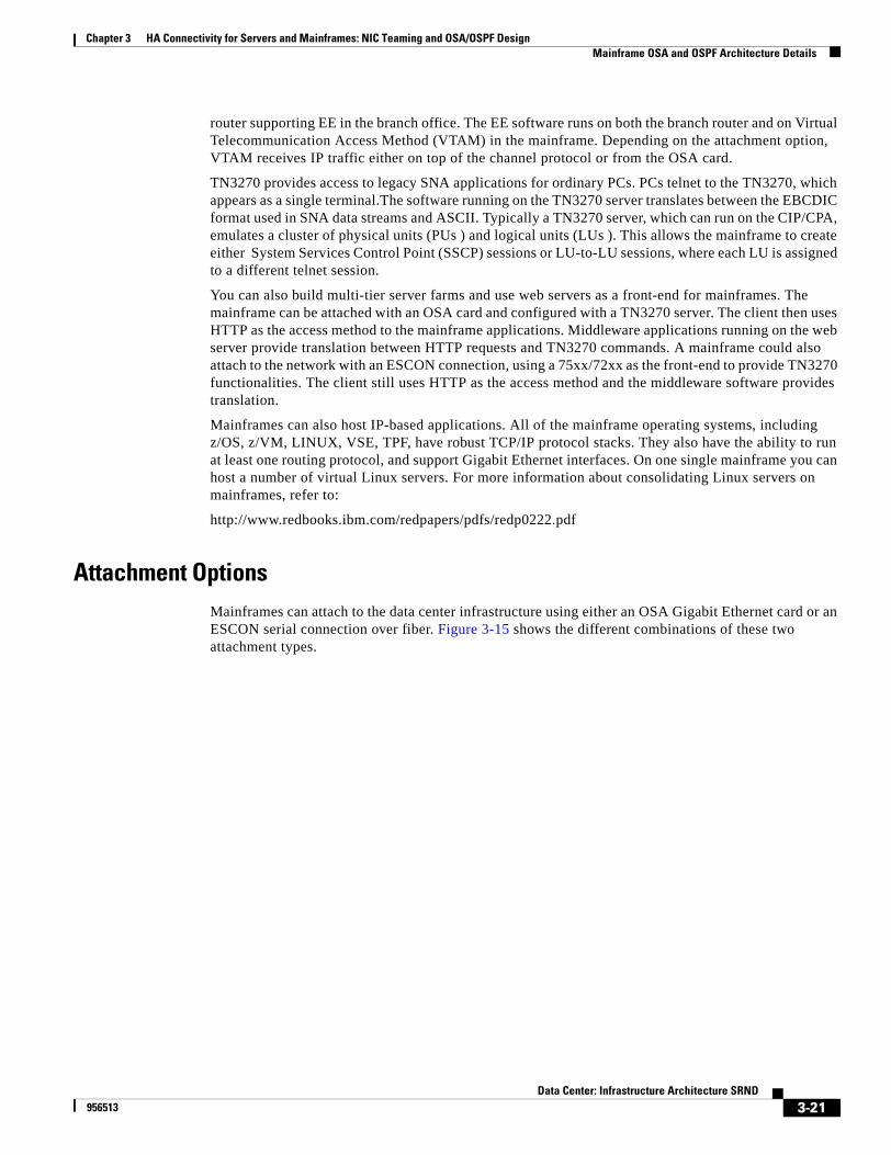
Chapter 3 HA Connectivity for Servers and Mainframes: NIC Teaming and OSA/OSPF DesignMainframe OSA and OSPF Architecture Details
router supporting EE in the branch office. The EE software runs on both the branch router and on Virtual Telecommunication Access Method (VTAM) in the mainframe. Depending on the attachment option, VTAM receives IP traffic either on top of the channel protocol or from the OSA card.
TN3270 provides access to legacy SNA applications for ordinary PCs. PCs telnet to the TN3270, which appears as a single terminal.The software running on the TN3270 server translates between the EBCDIC format used in SNA data streams and ASCII. Typically a TN3270 server, which can run on the CIP/CPA, emulates a cluster of physical units (PUs ) and logical units (LUs ). This allows the mainframe to create either System Services Control Point (SSCP) sessions or LU-to-LU sessions, where each LU is assigned to a different telnet session.
You can also build multi-tier server farms and use web servers as a front-end for mainframes. The mainframe can be attached with an OSA card and configured with a TN3270 server. The client then uses HTTP as the access method to the mainframe applications. Middleware applications running on the web server provide translation between HTTP requests and TN3270 commands. A mainframe could also attach to the network with an ESCON connection, using a 75xx/72xx as the front-end to provide TN3270 functionalities. The client still uses HTTP as the access method and the middleware software provides translation.
Mainframes can also host IP-based applications. All of the mainframe operating systems, including z/OS, z/VM, LINUX, VSE, TPF, have robust TCP/IP protocol stacks. They also have the ability to run at least one routing protocol, and support Gigabit Ethernet interfaces. On one single mainframe you can host a number of virtual Linux servers. For more information about consolidating Linux servers on mainframes, refer to:
http://www.redbooks.ibm.com/redpapers/pdfs/redp0222.pdf
Attachment OptionsMainframes can attach to the data center infrastructure using either an OSA Gigabit Ethernet card or an ESCON serial connection over fiber. Figure 3-15 shows the different combinations of these two attachment types.
3-21Data Center: Infrastructure Architecture SRND
956513
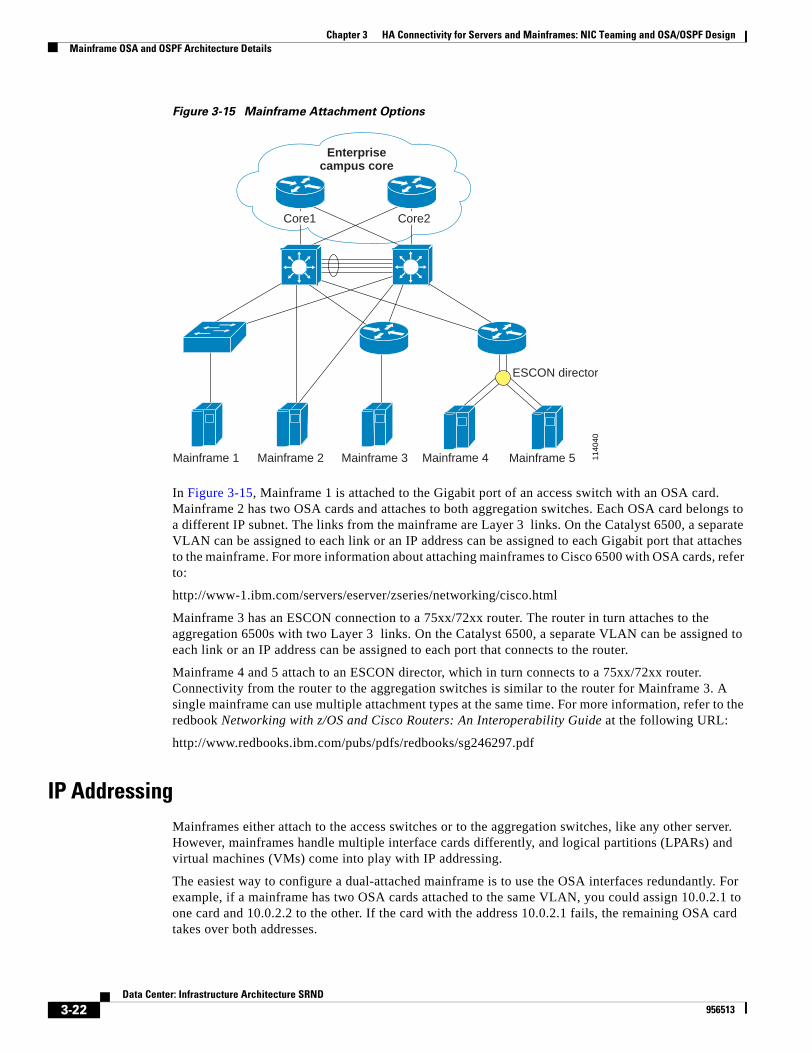
Chapter 3 HA Connectivity for Servers and Mainframes: NIC Teaming and OSA/OSPF DesignMainframe OSA and OSPF Architecture Details
Figure 3-15 Mainframe Attachment Options
In Figure 3-15, Mainframe 1 is attached to the Gigabit port of an access switch with an OSA card. Mainframe 2 has two OSA cards and attaches to both aggregation switches. Each OSA card belongs to a different IP subnet. The links from the mainframe are Layer 3 links. On the Catalyst 6500, a separate VLAN can be assigned to each link or an IP address can be assigned to each Gigabit port that attaches to the mainframe. For more information about attaching mainframes to Cisco 6500 with OSA cards, refer to:
http://www-1.ibm.com/servers/eserver/zseries/networking/cisco.html
Mainframe 3 has an ESCON connection to a 75xx/72xx router. The router in turn attaches to the aggregation 6500s with two Layer 3 links. On the Catalyst 6500, a separate VLAN can be assigned to each link or an IP address can be assigned to each port that connects to the router.
Mainframe 4 and 5 attach to an ESCON director, which in turn connects to a 75xx/72xx router. Connectivity from the router to the aggregation switches is similar to the router for Mainframe 3. A single mainframe can use multiple attachment types at the same time. For more information, refer to the redbook Networking with z/OS and Cisco Routers: An Interoperability Guide at the following URL:
http://www.redbooks.ibm.com/pubs/pdfs/redbooks/sg246297.pdf
IP AddressingMainframes either attach to the access switches or to the aggregation switches, like any other server. However, mainframes handle multiple interface cards differently, and logical partitions (LPARs) and virtual machines (VMs) come into play with IP addressing.
The easiest way to configure a dual-attached mainframe is to use the OSA interfaces redundantly. For example, if a mainframe has two OSA cards attached to the same VLAN, you could assign 10.0.2.1 to one card and 10.0.2.2 to the other. If the card with the address 10.0.2.1 fails, the remaining OSA card takes over both addresses.
Enterprisecampus core
1140
40
Mainframe 5Mainframe 4
ESCON director
Mainframe 3Mainframe 2Mainframe 1
Core1 Core2
3-22Data Center: Infrastructure Architecture SRND
956513
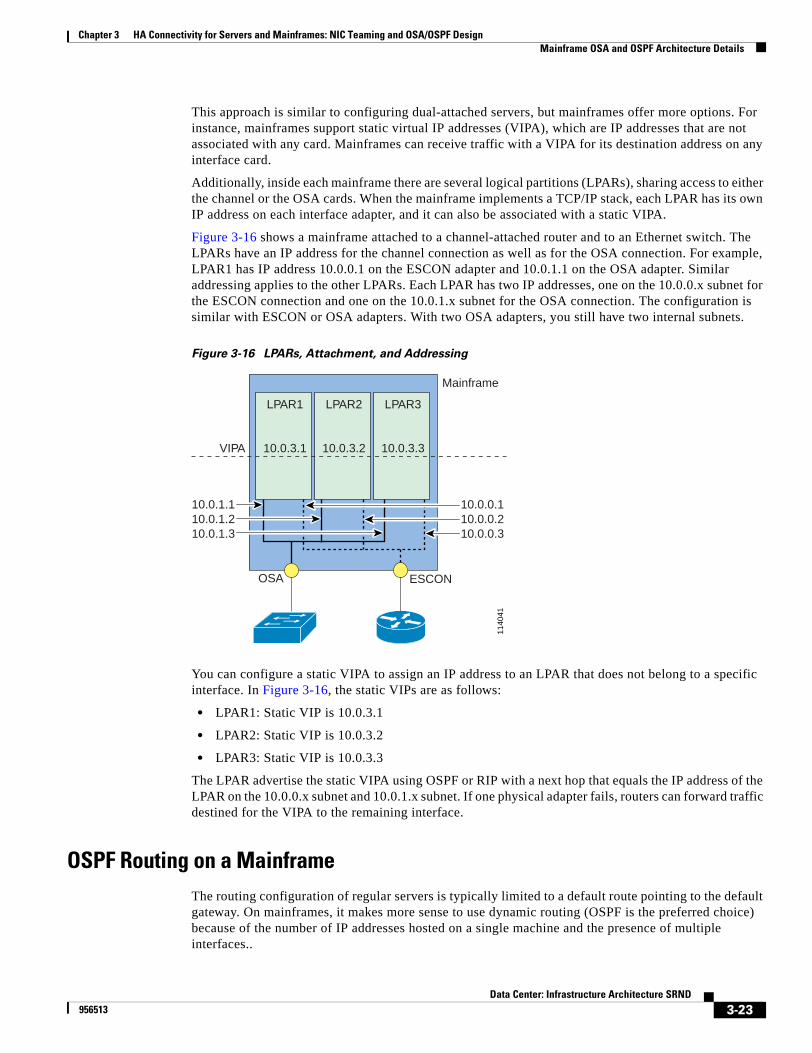
Chapter 3 HA Connectivity for Servers and Mainframes: NIC Teaming and OSA/OSPF DesignMainframe OSA and OSPF Architecture Details
This approach is similar to configuring dual-attached servers, but mainframes offer more options. For instance, mainframes support static virtual IP addresses (VIPA), which are IP addresses that are not associated with any card. Mainframes can receive traffic with a VIPA for its destination address on any interface card.
Additionally, inside each mainframe there are several logical partitions (LPARs), sharing access to either the channel or the OSA cards. When the mainframe implements a TCP/IP stack, each LPAR has its own IP address on each interface adapter, and it can also be associated with a static VIPA.
Figure 3-16 shows a mainframe attached to a channel-attached router and to an Ethernet switch. The LPARs have an IP address for the channel connection as well as for the OSA connection. For example, LPAR1 has IP address 10.0.0.1 on the ESCON adapter and 10.0.1.1 on the OSA adapter. Similar addressing applies to the other LPARs. Each LPAR has two IP addresses, one on the 10.0.0.x subnet for the ESCON connection and one on the 10.0.1.x subnet for the OSA connection. The configuration is similar with ESCON or OSA adapters. With two OSA adapters, you still have two internal subnets.
Figure 3-16 LPARs, Attachment, and Addressing
You can configure a static VIPA to assign an IP address to an LPAR that does not belong to a specific interface. In Figure 3-16, the static VIPs are as follows:
• LPAR1: Static VIP is 10.0.3.1
• LPAR2: Static VIP is 10.0.3.2
• LPAR3: Static VIP is 10.0.3.3
The LPAR advertise the static VIPA using OSPF or RIP with a next hop that equals the IP address of the LPAR on the 10.0.0.x subnet and 10.0.1.x subnet. If one physical adapter fails, routers can forward traffic destined for the VIPA to the remaining interface.
OSPF Routing on a MainframeThe routing configuration of regular servers is typically limited to a default route pointing to the default gateway. On mainframes, it makes more sense to use dynamic routing (OSPF is the preferred choice) because of the number of IP addresses hosted on a single machine and the presence of multiple interfaces..
1140
41
LPAR1
10.0.3.1
LPAR2
10.0.3.2
LPAR3
10.0.3.3VIPA
Mainframe
ESCON
10.0.1.110.0.1.210.0.1.3
10.0.0.110.0.0.210.0.0.3
OSA
3-23Data Center: Infrastructure Architecture SRND
956513
Chapter 3 HA Connectivity for Servers and Mainframes: NIC Teaming and OSA/OSPF DesignMainframe OSA and OSPF Architecture Details
Figure 3-17 Mainframe Attachment with OSA Cards and OSPF Routing
The left side of Figure 3-17 shows the physical attachment of mainframes with dual OSA cards, while the right side shows the logical topology. Integrating mainframes in the data center architecture does not change recommendations given in the section "Using OSPF.: We recommend a stub area or totally stubby area and to make either the core routers or the aggregation routers (MSFCs) the ABRs (see Figure 3-17). We also recommend ensuring that the mainframe does not become the default route for a given segment, which can be achieved by correctly configuring the OSPF priority on the aggregation switches.
For more information about attaching mainframes to Catalyst 6500 switches and using OSPF, refer to OSPF Design and Interoperability Recommendations for Catalyst 6500 and OSA-Express Environments available at: http://www-1.ibm.com/servers/eserver/zseries/networking/pdf/ospf_design.pdf
SysplexSysplex is a way to cluster a number of mainframes so they appear as a single machine. The system works around the failure of a mainframe component, such as an LPAR, and distributes new requests to the remaining machines. Components can belong to a single mainframe or to separate physical machines. Parallel Sysplex uses the Cross Coupling Facility (XCF) for exchanging messages between systems. Figure 3-18 illustrates the relation between Sysplex and other data center devices.
Area 0
1140
42
ABRABR
Default D
efau
lt
Layer 3
Laye
r 3
Laye
r 3
Laye
r 3
Laye
r 3
Layer 3
Layer 3
Layer 3
Enterprisecampus core
Core1 Core2
OSPF-STUB AREA
Mainframe 1 Mainframe 2
Laye
r 3
Laye
r 3
Layer 3
Mainframe 1 Mainframe 2
3-24Data Center: Infrastructure Architecture SRND
956513
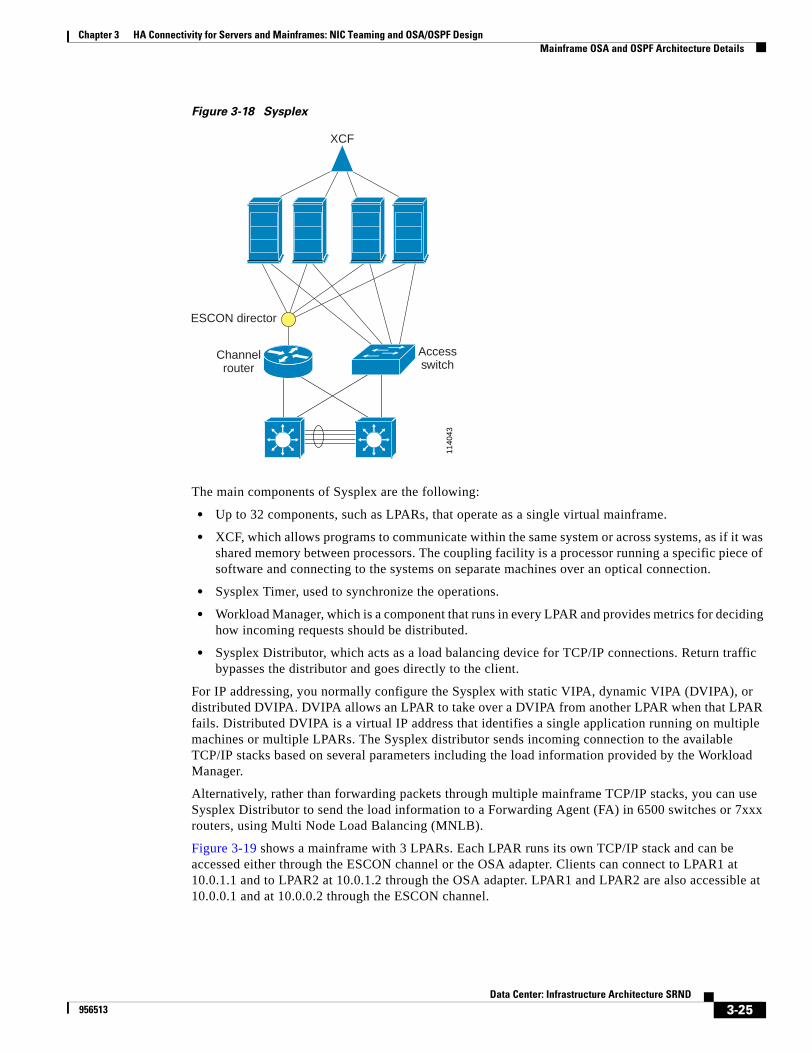
Chapter 3 HA Connectivity for Servers and Mainframes: NIC Teaming and OSA/OSPF DesignMainframe OSA and OSPF Architecture Details
Figure 3-18 Sysplex
The main components of Sysplex are the following:
• Up to 32 components, such as LPARs, that operate as a single virtual mainframe.
• XCF, which allows programs to communicate within the same system or across systems, as if it was shared memory between processors. The coupling facility is a processor running a specific piece of software and connecting to the systems on separate machines over an optical connection.
• Sysplex Timer, used to synchronize the operations.
• Workload Manager, which is a component that runs in every LPAR and provides metrics for deciding how incoming requests should be distributed.
• Sysplex Distributor, which acts as a load balancing device for TCP/IP connections. Return traffic bypasses the distributor and goes directly to the client.
For IP addressing, you normally configure the Sysplex with static VIPA, dynamic VIPA (DVIPA), or distributed DVIPA. DVIPA allows an LPAR to take over a DVIPA from another LPAR when that LPAR fails. Distributed DVIPA is a virtual IP address that identifies a single application running on multiple machines or multiple LPARs. The Sysplex distributor sends incoming connection to the available TCP/IP stacks based on several parameters including the load information provided by the Workload Manager.
Alternatively, rather than forwarding packets through multiple mainframe TCP/IP stacks, you can use Sysplex Distributor to send the load information to a Forwarding Agent (FA) in 6500 switches or 7xxx routers, using Multi Node Load Balancing (MNLB).
Figure 3-19 shows a mainframe with 3 LPARs. Each LPAR runs its own TCP/IP stack and can be accessed either through the ESCON channel or the OSA adapter. Clients can connect to LPAR1 at 10.0.1.1 and to LPAR2 at 10.0.1.2 through the OSA adapter. LPAR1 and LPAR2 are also accessible at 10.0.0.1 and at 10.0.0.2 through the ESCON channel.
1140
43
XCF
ESCON director
Channelrouter
Accessswitch
3-25Data Center: Infrastructure Architecture SRND
956513

Chapter 3 HA Connectivity for Servers and Mainframes: NIC Teaming and OSA/OSPF DesignConfiguration Details
Figure 3-19 Figure 19: DVIPA and Static VIPA
The interface used to access the LPAR normally doesn't matter when static VIPAs are used. A VIPA is equivalent to a loopback address on the LPAR. When you connect to 10.0.3.1 to access LPAR1, the routing devices downstream of the mainframe receive OSPF advertisements for 10.0.3.1 with a next-hop equal to 10.0.0.1 and 10.0.1.1. LPAR2 and LPAR3 can be accessed by 10.0.3.2 and 10.0.3.3 and the downstream router has two routes for each IP. Each route either points to the IP address of the OSA adapter or to the IP address of the ESCON channel.
Figure 19 shows a clustered DVIPA, but a DVIPA may also have a single instance. With a single instance of DVIPA, the IP address is moved around within the cluster if an application fails.
Distributed DVIPA is useful when you run the same application on all three LPARs. Users mainly connect to LPAR1, but if it fails, new incoming requests should go to LPAR2. To make this happen, share an IP address between LPAR1 and LPAR2. As shown in Figure 19, the DVIPA is the same on all three LPARs.
You can extend this example to a number of mainframes coupled with Sysplex. If each system runs a single LPAR, a static VIP provides high availability for each mainframe in case of failure of one interface adapter. DVIPA provides high availability for the applications because the application is shared across multiple machines.
For more information about the Sysplex environment refer to the IBM redbook TCP/IP in a Sysplex at:http://www.redbooks.ibm.com/pubs/pdfs/redbooks/sg245235.pdf
Configuration DetailsThis section describes the configuration details required for ensuring high availability for servers and mainframes in a data center. It includes the following topics:
• Speed and Duplex Settings
• Layer 2 Implementation
1140
44
LPAR1
10.0.3.1
10.0.80.1
LPAR2
10.0.3.2
10.0.80.1
LPAR3
10.0.3.3
10.0.80.1
VIPA
Mainframe
ESCON
10.0.1.110.0.1.210.0.1.3
10.0.0.110.0.0.210.0.0.3
OSA
DVIPA
3-26Data Center: Infrastructure Architecture SRND
956513
Chapter 3 HA Connectivity for Servers and Mainframes: NIC Teaming and OSA/OSPF DesignConfiguration Details
Speed and Duplex SettingsThe IEEE 802.3u autonegotiation protocol manages speed and duplex switch port settings. Server performance can be significantly reduced if the speed or duplex settings are incorrectly configured for a switch port interface by the autonegotiation protocol.. A mismatch may also occur when a manually configured speed or duplex setting is different from the manually configured speed or duplex setting on the attached port..
The result of a mismatch on Ethernet and FastEthernet ports is reduced performance or link errors. For Gigabit Ethernet ports, the link does not come up and statistics are not reported. To ensure correct port speed and duplex settings, configure both ports to autonegotiate both speed and duplex settings, or manually configure the same speed and duplex settings for the ports on both ends of the connection.
If these remedies do not help in correcting your negotiation issues, consult the documentation provided by the network adapter vendor. Some network adapter vendors, such as Intel, do not allow you to manually configure their downward-compatible Gigabit Ethernet network adapters for 1000 Mb. You can manually configure these adapters for half or full duplex at 10 Mb or 100 Mb, but they must be configured for autonegotiation to be used at 1000 Mb.
To identify a mismatch of duplex settings on an Ethernet or FastEthernet port, check for Frame Check Sequence (FCS) errors or late collisions when viewing the switch port statistics. Late collisions indicate that a half-duplex port is connected to a port set to full-duplex. FCS errors indicate that a full-duplex port is connected to a port set to half duplex.
Layer 2 ImplementationThe Layer 2 domain in the Data Center begins at the server, ends at the device that provides the default gateway for the servers, and can consist of several VLANs. This section describes the following Layer 2 features that are important to the Data Center server farm:
• Spanning tree
• PortFast
• BPDU Guard
Spanning Tree
Spanning tree ensures a loop-free topology when using a network that has physical loops, typically caused by redundant links. The servers in the data xenter do not bridge any traffic, and therefore have little or no interaction with spanning tree. Nevertheless, we recommend using Rapid Per VLAN Spanning Tree (PVST+) in the Data Center. This requires access layer switches that support 802.1s/1w, which provides fast convergence, and Rapid PVST+, which provides improved flexibility. Among the advantage of Rapid PVST+ in the server farm it is worth mentioning the speed of convergence and the fact that TCNs flush the MAC address table, which also accelerates the convergence of the network.
Rapid PVST+ can be enabled using the following commands:
IOS(config)# spanning-tree mode rapid-pvstCatOS (enable) set spantree mode rapid-pvst
For more information about Rapid PVST+, please see:
http://www.cisco.com/univercd/cc/td/doc/product/lan/cat6000/12_1e/swconfig/spantree.htm#1082480
3-27Data Center: Infrastructure Architecture SRND
956513
Chapter 3 HA Connectivity for Servers and Mainframes: NIC Teaming and OSA/OSPF DesignConfiguration Details
PortFast and BPDU Guard
Servers are typically connected to access ports., which carry traffic for a single VLAN. Make sure to explicitly set the port to be access with the command:
IOS(config-if)# switchport mode access
When a server is attached to an access port, or then a device other than a switch is attached to an access port, we recommend you enable PortFast. PortFast reduces the impact of a flapping NIC card, because it prevents a portfast port from generating TCNs.
You can enable portfast using the following commands:
IOS(config-if)# spanning-tree portfastCatOS (enable) set spantree portfast mod/port
In this and subsequent examples, replace mod with the module (slot) number and port with the port number.
Optionally, to perform the recommended configuration for ports providing access to servers on a CatOS-based access switch, enter the following command:
CatOS (enable) set port host mod/port
The set port host command enables spanning tree PortFast, sets channel mode to off, sets the trunk mode to off, and disables the dot1q tunnel feature, which reduces the time it takes for an end station to begin forwarding packets.
CatOS (enable) set trunk mod/port offCatOS (enable) set spantree portfast mod/port enableCatOS (enable) set port channel mod/port mode off
PortFast causes a Layer 2 interface that is configured as an access port to immediately enter the forwarding state, bypassing the listening and learning states for spanning tree convergence. With PortFast configured, a port is still running the Spanning Tree Protocol and can quickly transition to the blocking state if it receives superior BPDUs. However, PortFast should only be used on access ports because enabling PortFast on a port connected to a switch may create a temporary bridging loop.
BPDU Guard, when used in combination with PortFast, can prevent bridging loops by shutting down a port that receives a BPDU. When globally configured, BPDU Guard is only effective on ports that are configured for PortFast. Under normal conditions, interfaces that are configured for PortFast do not receive BPDUs. Reception of BPDUs by an interface that is configured for PortFast is an indication of an invalid configuration, such as connection of an unauthorized device. When BPDU Guard takes a port out of service, you must manually put it back in service. You can also configure BPDU Guard at the interface level. When configured at the interface level, BPDU Guard shuts the port down as soon as the port receives a BPDU, regardless of the PortFast configuration.
To enable BPDU Guard, use the following commands:
IOS (config-if)# spanning-tree portfast bpduguardCatOS (enable) set spantree portfast bpdu-guard mod/port enable
An edge port is defined as a port that connects to a host or a service appliance. It is important to assign the PortFast and Trunkfast definitions to the eligible ports because 802.1w categorizes ports into edge and non-edge, which provides two main benefits. First, if flapping occurs on edge-ports, 802.1w does not generate a topology change notification. Second, an edge port does not change its forwarding state when there is a topology recalculation.
For more information about PortFast, BPDU Guard, and Trunkfast, please see: http://www.cisco.com/univercd/cc/td/doc/product/lan/cat6000/12_1e/swconfig/stp_enha.htm
3-28Data Center: Infrastructure Architecture SRND
956513
Chapter 3 HA Connectivity for Servers and Mainframes: NIC Teaming and OSA/OSPF DesignConfiguration Details
Port Security
Port security allows you to specify MAC addresses for each port or to permit a limited number of MAC addresses. When a secure port receives a packet, the source MAC address of the packet is compared to the list of secure source addresses that were manually configured or autoconfigured (learned) on the port. If a MAC address of a device attached to the port differs from the list of secure addresses, the port either shuts down permanently (default mode), shuts down for the time you have specified, or drops incoming packets from the insecure host. The port's behavior depends on how you configure it to respond to a security violator.
Cisco recommends that you configure the port security feature to issue a shutdown instead of dropping packets from insecure hosts through the restrict option. The restrict option may fail under the load of an attack and the port is disabled anyway. The configuration commands are the following ones:
aggregation(config-if)# switchport port-security maximum <maximum number of mac addresses>aggregation(config-if)# switchport port-security violation shutdownaggregation(config-if)# switchport port-security aging time <time in minutes>
The number of mac addresses that need to be allowed on a port depends on the server configuration. Multi-homed servers typically use a number of MAC addresses that equals the number of NIC cards + 1 (if a virtual adapter MAC addresses is defined).
Server Port Configuration
Access ports carry traffic for a single VLAN. You typically connect servers to access ports.
Additionally, devices like SSL offloaders, caches or the client side (and sometimes the server side) of a CSS are connected to an access port. When a server is attached to an access port, or when a device other than a switch is attached to an access port, Cisco recommends that you enable portfast with the following command:
(config-if)# spanning-tree portfast
For more information about portfast see:
http://www.cisco.com/univercd/cc/td/doc/product/lan/cat6000/12_1e/swconfig/stp_enha.htm
The recommended configuration for the ports that provide access to the servers, if you are running CatOS on your access switches, is:
set port host a/b
The following is an example of a complete configuration for a switchport that connects to a dual-homed server configured for fault tolerance:
interface FastEthernet6/1 no ip address switchport switchport access vlan 105 switchport mode access switchport port-security maximum 2 switchport port-security violation shutdown switchport port-security aging time 20 no cdp enable spanning-tree portfast spanning-tree bpduguard enable!
3-29Data Center: Infrastructure Architecture SRND
956513

Chapter 3 HA Connectivity for Servers and Mainframes: NIC Teaming and OSA/OSPF DesignConfiguration Details
3-30Data Center: Infrastructure Architecture SRND
956513
Data C956513
C H A P T E R 4
Data Center Infrastructure ConfigurationThis chapter provides configuration procedures and sample listings for implementing the recommended infrastructure architecture, including routing between the data center and the core, switching within the server farm, and establishing mainframe connectivity. It includes the following sections:
• Configuring Network Management, page 4-1
• VLAN Configuration, page 4-3
• Spanning Tree Configuration, page 4-6
• VLAN Interfaces and HSRP, page 4-8
• Switch-To-Switch Connections Configuration, page 4-9
• Server Port Configuration, page 4-12
• Sample Configurations, page 4-14
Configuring Network ManagementThis section contains some basic network management best practices to reduce network vulnerabilities and simplify troubleshooting that you should consider before configuring the Layer 2 and Layer 3 aspects of the recommended design. You can use the configuration in this section for initial setup. Fine tuning and advanced configurations, such as AAA role-based access, AAA accounting, SNMP configurations, and syslog server optimizations are beyond the scope of this document.
Username and Passwords
You can either define usernames and passwords on the local database of each switch or on a centralized access control server. We recommend the latter approach, using Authentication Authorisation and Accounting (AAA) technology in conjunction with a Terminal Access Controller Access Control System (TACACS) or with a RADIUS server: TACACS provides more granular access control. Username and passwords in the local database can be used if the access control server becomes unavailable.
The following command defines a local username and password:username local username secret 0 local password
The command for defining the password for Privileged mode is:enable secret 0 enable password
4-1enter: Infrastructure Architecture SRND
Chapter 4 Data Center Infrastructure ConfigurationConfiguring Network Management
Access to the network devices from a virtual terminal line (VTY) uses the TACACS servers and falls back to local authentication if the TACACS server is unavailable:aaa new-modelaaa authentication login default group tacacs+ localaaa authorization exec default group tacacs+ if-authenticated localtacacs-server host server IP addresstacacs-server key same key as the server
Access to the console can be authenticated using the access control server, or if the authentication is completed on the commserver, you can choose to automatically give access to the switch or router. In an initial deployment phase, we used the following configuration to avoid being locked out. This relies on local authentication and doesn’t involve the use of the TACACS server, but it provides better security than no authentication at all:aaa authentication login LOCALAUTHC localline con 0exec-timeout 30 0password 0 line passwordlogin authentication LOCALAUTHC
The use of the LOCALAUTHC authentication list overrides the default authentication list. You can also use the line password instead of local authentication in which case the configuration of the authentication list would look like:aaa authentication login LOCALAUTHC line
Some commands, such as the enable or username, provide the option to encrypt the password by using the secret keyword. To minimize the chance of leaving passwords in clear text use the service password-encrypt option.
VTY Access
Access to the switch or router over a VTY line is controlled with an access list and the preferred transport protocol is SSH. The following is a sample configuration:line vty 0 4 access-class 5 in exec-timeout 30 0 transport input ssh
Before you can use the transport input ssh command in this configuration, you must first complete the following steps:
• Configure initial authentication (either local or via an ACS server).
• Define a domain name: ip domain-name name
• Generate the crypto key pairs: crypto key gen rsa usage-key modulus key size
• Define a timeout for the I/O response: ip ssh time-out timeout
• Define the number of password attempts that the client is allowed: ip ssh authentication-retries number of retries
• Choose the SSH version: ip ssh version ssh version
4-2Data Center: Infrastructure Architecture SRND
956513
Chapter 4 Data Center Infrastructure ConfigurationVLAN Configuration
Note To disable SSH use the crypto key zeroise command
SNMP
Configuring SNMP is beyond the scope of this document. It is recommended disabling SNMP until you are able to configure it properly, by entering the following command:no snmp-server
Logging
To simplify troubleshooting and security investigations, you should monitor router subsystem information received from the logging facility (syslog). You can adjust the amount of detail in the logging information. A good level of general logging for everyday use is informational. You can capture much more detail using the debug level, but that level should only be used on a temporary basis. The syslog messages should be sent to a server because when you log messages to the memory buffer, the information is lost when the switch or router is reset.
Logging to the console is not recommended because users don't spend much time actually connected to the console after initial installation and configuration is complete. The commands for basic logging configuration are as follows.
To configure timestamps for the log messages, enter the following command:service timestamps log datetime msec localtime show-timezone
To configure a syslog server, enter the following commands:logging IP address of the server
no logging consoleno logging monitorlogging buffered 65536 informational
VLAN ConfigurationFigure 4-1 illustrates the data center reference architecture to which the following configuration listings apply.
4-3Data Center: Infrastructure Architecture SRND
956513
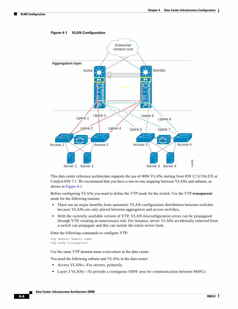
Chapter 4 Data Center Infrastructure ConfigurationVLAN Configuration
Figure 4-1 VLAN Configuration
This data center reference architecture supports the use of 4096 VLANs starting from IOS 12.1(11b) EX or Catalyst IOS 7.1. We recommend that you have a one-to-one mapping between VLANs and subnets, as shown in Figure 4-1.
Before configuring VLANs you need to define the VTP mode for the switch. Use the VTP transparent mode for the following reasons:
• There are no major benefits from automatic VLAN configuration distribution between switches because VLANs are only placed between aggregation and access switches,.
• With the currently available version of VTP, VLAN misconfiguration errors can be propagated through VTP, creating an unnecessary risk. For instance, server VLANs accidentally removed from a switch can propagate and this can isolate the entire server farm.
Enter the following commands to configure VTP:vtp domain domain namevtp mode transparent
Use the same VTP domain name everywhere in the data center.
You need the following subnets and VLANs in the data center:• Access VLANs—For servers, primarily
• Layer 3 VLANs—To provide a contiguous OSPF area for communication between MSFCs
1140
32
Aggregation layer
Access 1 Access 2 Access 3 Access 4
Active Standby
Enterprisecampus core
Server 1 Server 4Server 3Server 2
Uplink 3Uplink 1
Uplink 2 Uplink 4
Uplink 8
Uplink 7
Uplink 6
Uplink 5
4-4Data Center: Infrastructure Architecture SRND
956513
Chapter 4 Data Center Infrastructure ConfigurationVLAN Configuration
• Service VLANs—To forward traffic to the service modules, such as the client VLAN of a content switch
• Fault tolerant VLANs—For redundancy with CSM, FWSM, CSS, and so forth
• Additional VLANs —Used by the system for routed ports as well as WAN ports
If you want to use 4000 VLANs, you have to enable the mac address reduction command as follows: spanning-tree extend system-id
The mac address reduction option modifies the bridge identifier so that instead of 16 bits of bridge priority, you only use 4 bits. That leaves 12 bits to identify the VLAN and that allows you to use up to 4,000. ) You use 6 bytes are for the bridge MAC address. While the implication in terms of the bridge ID is unnoticeable, the priority of a root and secondary root are slightly different from configurations without MAC address reduction:
• Root bridge priority: 24576 (instead of 8192)
• Secondary root bridge priority: 28672 (instead of 16384)
• Regular bridge priority: 32768
The specific spanning-tree configuration is explained later.
To verify that the mac address reduction option is enabled, use the show spanning-tree summary command.
Remember to enable mac address reduction on all the switches in the data center.
Not all 4,000 VLANs are available for your use because certain VLANs are internally used by the switch. These internal VLANs used to be carved out from the total VLAN range as follows:
• 1 – 1005 normal VLANs
• 1002 FDDI, 1003 Token Ring, 1004 FDDI Net, 1005 Token Ring Net
• 1006 – 4094 internal VLANs
• 1006 – 4094 extended VLANs
• 4095 protocol filtering
In previous versions of the software, internal VLANs were allocated ascending from 1006, and as a consequence we previously recommended using extended VLANs from 4094 down to avoid overlapping with the internal VLANs. With the current release of software, you can change the allocation policy so that internal VLANs are allocated from 4094 down. This lets you keep the extended VLAN numbering ascending from 1006.
To implement this policy use the following command:vlan internal allocation policy descending
You can theoretically either create VLANs from the Config mode or from the VLAN database configuration mode. However, do not use the VLAN database configuration mode. We recommend using Config mode for two reasons:
• Extended VLANs can only be configured in Config mode.
• If you are using RPR/RPR+, the VLANs defined in VLAN database configuration are not synchronized to the standby supervisor.
To create the VLANs enter the following commands:
(config)# VLAN 10
4-5Data Center: Infrastructure Architecture SRND
956513
Chapter 4 Data Center Infrastructure ConfigurationSpanning Tree Configuration
(config-vlan)# name my_vlan
When configuring VLANs with the internal allocation policy descending option, follow these guidelines:• Allocate normal VLANs from 1 up
• Allocate extended VLANs from 1006 up
Spanning Tree ConfigurationThis section describes the recommended configuration for using spanning tree in a data center infrastructure. It includes the following sections:
• Rapid PVST+
• MST
• Protection From Loops
• Configuring Spanning-Tree with Bridging Appliances
Rapid PVST+
To configure Rapid PVST+ in native IOS enter the following command:spanning-tree mode rapid-pvst
We recommend that you have a single spanning-tree topology in the data center. In the event that you need to load balance traffic to the uplinks between the access and the aggregation switches, assign different priorities for even VLANs and odd VLANs.
The first configuration step is to assign the root and the secondary root switches. Because our recommendation is to not do uplink load balancing in the data center, the examples in this design document show one aggregation (aggregation1) switch as the root for all the instances and the other aggregation switch as the root for all the other instances (aggregation2). The configuration for Native IOS on aggregation1 is as follows:spanning-tree vlan 3,5,10,20,30,100,200 root primary
The configuration on aggregation2 for Native IOS is as follows:spanning-tree vlan 3,5,10,20,30,100,200 root secondary
With the mac address reduction option enabled, the above commands assign priorities as follows:• Root bridge priority ― 24576 (instead of 8192 without mac address reduction)
• Secondary root bridge priority ― 28672 (instead of 16384 without mac address reduction)
• Regular bridge priority ¯ 32768
Note With Rapid PVST+ there is no further need for uplinkfast and backbonefast. Just configure Rapid PVST+ in all the devices that belong to the same VTP domain.
4-6Data Center: Infrastructure Architecture SRND
956513
Chapter 4 Data Center Infrastructure ConfigurationSpanning Tree Configuration
MST
We recommend creating a separate instance for the data VLANs (different from MST 0) and map VLANs to that MST instance.
The association between VLANs and instances is defined in the spanning-tree region configuration. A region for spanning-tree is defined by an alphanumeric identifier, by a revision number, and by a table that maps each VLANs to its respective instance.
The region information in the data center switches must match or they will belong to different regions. The region concept ensures that you have consistent mapping between VLANs and MST instances. If you notice that you have ports categorized by spanning-tree as a boundary port, the problem is probably related to an inconsistent region configuration.
The following are the configuration commands using Catalyst 6500 IOS:spanning-tree mst configuration name data_center_mst revision 10 instance 1 vlan 1-1000
The same name and same revision number, as well as the instance mapping, must match on all data center switches. Notice that you do not map any VLAN to instance 0.
Cisco recommends that you have a single spanning-tree topology in the data center. In the event that you need to load balance traffic to the uplinks from the access to the aggregation switches, you then configure two instances in addition to the IST. The total number of instances ranges between 2 and 3 depending on the configuration. This is still a small number when compared to the number of spanning tree instances that the switch would have to maintain with PVST+.
The configuration steps to assign the root and the secondary root switches are the same as PVST+. Because our recommendation is to not do uplink load balancing in the data center, the examples in this design document show one aggregation (aggregation1) switch as the root for all the instances and the other aggregation switch as the root for all the other instances (aggregation2). The configuration on aggregation1 is as follows:spanning-tree mst 0 root primaryspanning-tree mst 1 root primary
The configuration on aggregation2 is as follows:spanning-tree mst 0 root secondaryspanning-tree mst 1 root secondary
With the mac address reduction option enabled, these commands assign priorities as follows:• Root bridge priority ¯ 24576 (instead of 8192 without mac address reduction)
• Secondary root bridge priority ¯ 28672 (instead of 16384 without mac address reduction)
• Regular bridge priority ¯ 32768
Protection From Loops
The configuration of LoopGuard for IOS is as follows:(config)#spanning-tree loopguard default
4-7Data Center: Infrastructure Architecture SRND
956513

Chapter 4 Data Center Infrastructure ConfigurationVLAN Interfaces and HSRP
This command enables LoopGuard globally on the entire switch. We recommend enabling LoopGuard on all the ports at both aggregation and access switches.
With rapid spanning tree, UDLD can still be used to prevent loops caused by bad wiring of fiber links. UDLD cannot detect loops that occur after the topology has already converged. A link that suddenly becomes unidirectional causes the spanning-tree topology to converge within 7 seconds. It takes 6 seconds to detect missing BPDUs and 1 second to send the proposal and receive an agreement. UDLD can detect a unidirectional link in 21 seconds with a message interval of 7 seconds, which is more than the time it takes for spanning-tree to converge.
The conclusion is that LoopGuard and UDLD complement each other, and therefore UDLD should also be enabled globally: To enable these features, enter the following commands:aggregation2(config)#udld enable
agg2(config)#udld message time 7
Another common cause of loops, besides failures that can cause loops, are devices that bridge VLANs, like content switches used in bridge mode. Content switches typically do not forward BPDUs, which means that when two of them are active and bridge the same VLAN, a loop occurs.
If you are using such a device, before bridging VLANs, make sure that the two devices can see each other and agree on their active / backup role. On the CSM, first configure the fault tolerant VLAN, assign the client and server VLAN, and then bridge them.
VLAN Interfaces and HSRPOn the aggregation switches, you can either assign IP addresses to a Layer 3 interface or to a VLAN interface. This type of VLAN interface is called a switched VLAN interface (SVI). The maximum number of SVIs that you can configure on a Catalyst 6500 is 1,000, despite the fact that the maximum number of VLANs that can be switched is 4,000.
Figure 4-2 Illustrates the HSRP configuration with a 1-to-1 mapping between the Layer 3 topology and the Layer 2 topology.
4-8Data Center: Infrastructure Architecture SRND
956513
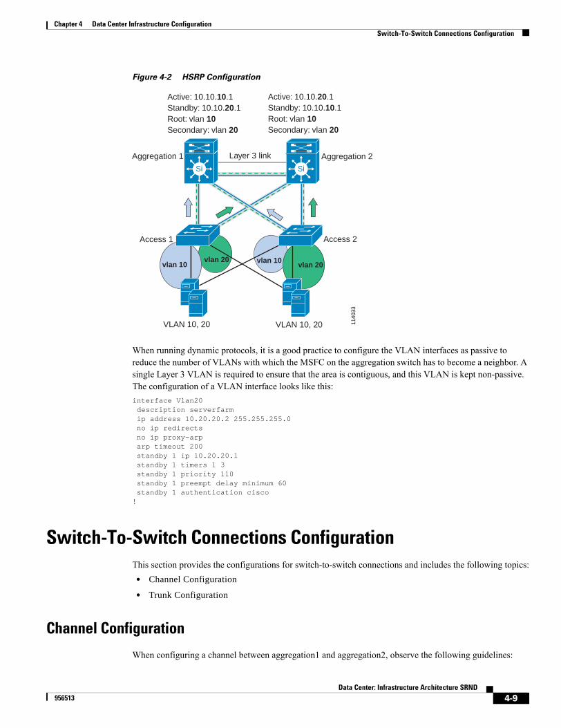
Chapter 4 Data Center Infrastructure ConfigurationSwitch-To-Switch Connections Configuration
Figure 4-2 HSRP Configuration
When running dynamic protocols, it is a good practice to configure the VLAN interfaces as passive to reduce the number of VLANs with which the MSFC on the aggregation switch has to become a neighbor. A single Layer 3 VLAN is required to ensure that the area is contiguous, and this VLAN is kept non-passive. The configuration of a VLAN interface looks like this:interface Vlan20 description serverfarm ip address 10.20.20.2 255.255.255.0 no ip redirects no ip proxy-arp arp timeout 200 standby 1 ip 10.20.20.1 standby 1 timers 1 3 standby 1 priority 110 standby 1 preempt delay minimum 60 standby 1 authentication cisco!
Switch-To-Switch Connections ConfigurationThis section provides the configurations for switch-to-switch connections and includes the following topics:
• Channel Configuration
• Trunk Configuration
Channel Configuration
When configuring a channel between aggregation1 and aggregation2, observe the following guidelines:
1140
33
Layer 3 link
vlan 20vlan 10 vlan 20
vlan 10
Aggregation 1
Access 1 Access 2
Aggregation 2
VLAN 10, 20 VLAN 10, 20
Active: 10.10.10.1Standby: 10.10.20.1Root: vlan 10Secondary: vlan 20
Active: 10.10.20.1Standby: 10.10.10.1Root: vlan 10Secondary: vlan 20
Si Si
4-9Data Center: Infrastructure Architecture SRND
956513
Chapter 4 Data Center Infrastructure ConfigurationSwitch-To-Switch Connections Configuration
• Use multiple ports from different line cards to minimize the risk of losing connectivity between the aggregation switches.
• Use Link Aggregate Control Protocol (LACP) active on aggregation1
• Use LACP passive on aggregation2
The following example shows the channel configuration between the ports Giga1/1, Giga1/2, Giga4/15, and Giga4/16 for aggregation1.interface GigabitEthernet1/1 description to_aggregation2 channel-group 2 mode active channel-protocol lacp
interface GigabitEthernet1/2 description to_aggregation2 channel-group 2 mode active channel-protocol lacp
interface GigabitEthernet9/15 description to_aggregation2 channel-group 2 mode active channel-protocol lacp
interface GigabitEthernet9/16 description to_aggregation2 channel-group 2 mode active channel-protocol lacp
The configuration for aggregation2 is the same with the exception that the channel mode is passive, as shown in the following command:channel-group 2 mode passive
For more information about configuring channels, refer to:
http://www.cisco.com/univercd/cc/td/doc/product/lan/cat6000/12_1e/swconfig/channel.htm
Trunk Configuration
You can configure trunks between the following network devices:• Aggregation switches, which carry practically all of the VLANs
• Access switches and aggregation switches, which carry only the server VLANs
• Aggregation switches and the service appliances
To define the VLANs allowed on a trunk, enter the following command:switchport trunk allowed vlan 10,20
You can modify the list of the VLANs allowed on a trunk with the following commands in Native IOS:switchport trunk allowed vlan add vlan numberswitchport trunk allowed vlan remove vlan number
The recommended trunk encapsulation is 802.1q, mainly because it is the standard. The configuration in Catalyst 6500 IOS is as follows:switchport trunk encapsulation dot1q
4-10Data Center: Infrastructure Architecture SRND
956513
Chapter 4 Data Center Infrastructure ConfigurationSwitch-To-Switch Connections Configuration
You can force a port to be a trunk by entering the following command:switchport mode trunk
This mode puts the port into permanent trunk mode and sends Dynamic Trunking Protocol (DTP) frames to turn the neighboring port into a trunk as well. If the trunk does not form, verify the VTP domain configuration. VTP domain names must match between the neighboring switches.
The trunks that connect the aggregation to the access switches should also have Root Guard configured. A sample configuration looks like the following:interface GigabitEthernet9/1 description to_access no ip address switchport switchport trunk encapsulation dot1q switchport trunk allowed vlan 20,105,110,140 switchport mode trunk spanning-tree guard root!
The trunks that connect the access switches to the aggregation switches look like this:interface GigabitEthernet1/1 description toaggregation1 no ip address switchport switchport trunk encapsulation dot1q switchport trunk allowed vlan 20,105,110,140 switchport mode trunk!
A sample configuration for the trunks that connect the aggregation switches looks like this:interface GigabitEthernet1/1 description toaggregation2 no ip address logging event link-status switchport switchport trunk encapsulation dot1q switchport trunk allowed vlan 3,5,10,20,30,40,100,105,110,140,200,201,300 switchport mode trunk channel-group 2 mode active channel-protocol lacp!
We recommend that you configure the switches to tag all traffic on trunks with the VLAN tag. In 802.1q, the native VLAN of a port is carried untagged, which might lead to misconfigurations. To avoid misconfigurations, use the dot1q tagged all option, as shown below:vlan dot1q tag native
Use 802.1q to configure trunks to external devices such as a CSS.
Configuration of trunks to service modules, such as a CSM or a FWSM, is either implicit or explicit. Implicit means that the device sees all the VLANs by default. Explicit means that the devices are aided by using an explicit command. In the case of the FWSM the commands are as follows:firewall vlan-group vlan-group-number vlan listfirewall module module vlan-group vlan-group-number
In the case of the SSLSM the commands are:ssl-proxy module module allowed-vlan vlan list
4-11Data Center: Infrastructure Architecture SRND
956513

Chapter 4 Data Center Infrastructure ConfigurationServer Port Configuration
It is important to assign PortFast and TrunkFast to the eligible ports because 802.1s/1w categorizes ports into edge and non-edge. This is explained in detail the document Data Center Infrastructure Design.
You should enable TrunkFast on the trunks that go to a CSS or any external service appliance connected to the aggregation switches over a trunk. Enter the following command:spanning-tree portfast trunk
Special trunks are used on internal ports by service modules installed in a Catalyst switch to connect to the switch backplane. These ports cannot be manually configured even if you can see the channels. In the current release of softrware, the trunks that connect to the service modules are automatically configured with TrunkFast.
Server Port ConfigurationYou typically connect servers to access ports, which carry traffic for a single VLAN. The key goals of the configuration of a server port include the following:
• Fast linkup when a server is attached to the port
• Avoiding the generation of TCN BPDUs when a server port is flapping
• Avoiding the change of topology when somebody accidentally attaches a switch to a port that should only connect to a server.
This section includes recommendations for server port configuration and includes the following topics:• Speed and Duplex Settings
• PortFast and BPDU Guard
Speed and Duplex SettingsThe IEEE 802.3u autonegotiation protocol manages speed and duplex switch port settings. Server performance can be damaged if the speed or duplex settings are incorrectly configured for a switch port interface by the autonegotiation protocol.. A mismatch may also occur when a manually configured speed or duplex setting is different from the manually configured speed or duplex setting on the attached port..
The result of a mismatch on Ethernet and FastEthernet ports is reduced performance or link errors. For Gigabit Ethernet ports, the link does not come up and statistics are not reported. To ensure correct port speed and duplex settings, either configure both ports to autonegotiate both speed and duplex settings, or manually configure the same speed and duplex settings for the ports on both ends of the connection.
If these remedies do not correct your negotiation issues, consult the documentation provided by the network adapter vendor. Some network adapter vendors, such as Intel, do not allow you to manually configure their downward-compatible Gigabit Ethernet network adapters for 1000 Mb. You can manually configure these adapters for half or full duplex at 10 Mb or 100 Mb, but they must be configured for autonegotiation to be used at 1000 Mb.
To identify a mismatch of duplex settings on an Ethernet or FastEthernet port, check for Frame Check Sequence (FCS) errors or late collisions when viewing the switch port statistics. Late collisions indicate that a half-duplex port is connected to a port set to full-duplex. FCS errors indicate that a full-duplex port is connected to a port set to half duplex.
4-12Data Center: Infrastructure Architecture SRND
956513
Chapter 4 Data Center Infrastructure ConfigurationServer Port Configuration
PortFast and BPDU GuardServers are typically connected to access ports., which carry traffic for a single VLAN. Make sure to explicitly set the port for “access” with the command:
IOS(config-if)# switchport mode access
When a server or any device other than a switch is attached to an access, we recommend you enable PortFast. PortFast reduces the impact of a flapping NIC card by preventing the PortFast port from generating TCNs. To enable PortFast enter the following command:
IOS(config-if)# spanning-tree portfast
PortFast causes a Layer 2 interface that is configured as an access port to immediately enter the forwarding state, bypassing the Listening and Learning states for spanning tree convergence. With PortFast configured, a port is still running the Spanning Tree Protocol and can quickly transition to the blocking state if it receives superior BPDUs. However, Portfast should only be used on access ports because enabling PortFast on a port connected to a switch may create a temporary bridging loop.
BPDU Guard, when used in combination with Portfast, can prevent bridging loops by shutting down a port that receives a BPDU. When globally configured, BPDU Guard is only effective on ports that are configured for PortFast. Under normal conditions, interfaces that are configured for PortFast do not receive BPDUs. Reception of BPDUs by an interface that is configured for PortFast is an indication of an invalid configuration, such as a connection from an unauthorized device. When BPDU Guard takes a port out of service, you must manually put it back in service. You can also configure BPDU Guard at the interface level. When configured at the interface level, BPDU Guard shuts the port down as soon as the port receives a BPDU, regardless of the PortFast configuration.
To enable BPDU Guard, enter the following command:
IOS (config-if)# spanning-tree portfast bpduguard
An edge port is defined as a port that connects to a host or a service appliance. It is important to assign the Portfast and TrunkFast definitions to the eligible ports because 802.1w categorizes ports into edge and non-edge ports. This provides two benefits. First, if flapping occurs on edge-ports, 802.1w does not generate a topology change notification. Second, an edge port does not change its forwarding state when there is a topology recalculation.
For more information about PortFast, BPDU Guard, and TrunkFast, please see: http://www.cisco.com/univercd/cc/td/doc/product/lan/cat6000/12_1e/swconfig/stp_enha.htm
Port SecurityPort security allows you to specify MAC addresses for each port or to permit a limited number of MAC addresses. When a secure port receives a packet, the source MAC address of the packet is compared to the list of permitted source addresses that were manually configured or learned on the port. If a MAC address of a device attached to the port differs from the list of secure addresses, the port either shuts down permanently (default mode), shuts down for the time you have specified, or drops incoming packets from the insecure host. The port behavior depends on how you configure it to respond to security violations.
We recommend that you configure the port security feature to issue a shutdown rather than using the restrict option to drop packets from insecure hosts. The restrict option may fail under the load of an attack and the port is disabled anyway. The required configuration commands are as follows:
aggregation(config-if)# switchport port-security maximum maximum number of mac addressesaggregation(config-if)# switchport port-security violation shutdown
4-13Data Center: Infrastructure Architecture SRND
956513
Chapter 4 Data Center Infrastructure ConfigurationSample Configurations
aggregation(config-if)# switchport port-security aging time time in minutes
The number of mac addresses allowed on a port depends on the server configuration. Multi-homed servers typically use a number of mac addresses that equals the number of NIC cards + 1 (if a virtual adapter MAC addresses is defined).
Configuration ExampleThe following is an example of a complete configuration for a switch port that connects to a dual-homed server configured for fault tolerance:
interface FastEthernet6/1 no ip address switchport switchport access vlan 105 switchport mode access switchport port-security maximum 2 switchport port-security violation shutdown switchport port-security aging time 20 no cdp enable spanning-tree portfast spanning-tree bpduguard enable!
Sample ConfigurationsThis section provides the full sample configurations for each device in the recommended design. It includes the following sections:
• Aggregation1
• Aggregation2
• Access
Aggregation1
The configuration for the aggregation1 switch is as follows:!no snmp-server!version 12.1no service padservice timestamps debug uptimeservice timestamps log datetime msec localtime show-timezoneservice password-encryption!hostname agg1!logging buffered 65536 informationalno logging consoleno logging monitoraaa new-modelaaa authentication login default group tacacs+ localaaa authentication login LOCALAUTHC localaaa authorization exec default group tacacs+ if-authenticated local
4-14Data Center: Infrastructure Architecture SRND
956513
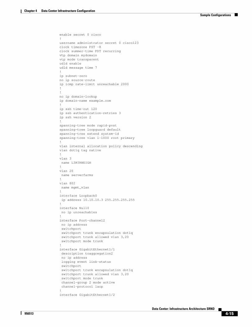
Chapter 4 Data Center Infrastructure ConfigurationSample Configurations
enable secret 0 cisco!username administrator secret 0 cisco123clock timezone PST -8clock summer-time PDT recurringvtp domain mydomainvtp mode transparentudld enableudld message time 7!ip subnet-zerono ip source-routeip icmp rate-limit unreachable 2000!!no ip domain-lookupip domain-name example.com!ip ssh time-out 120ip ssh authentication-retries 3ip ssh version 2!spanning-tree mode rapid-pvstspanning-tree loopguard defaultspanning-tree extend system-idspanning-tree vlan 1-1000 root primary!vlan internal allocation policy descendingvlan dot1q tag native !vlan 3 name L3RTRNEIGH!vlan 20 name serverfarms!vlan 802 name mgmt_vlan!interface Loopback0 ip address 10.10.10.3 255.255.255.255!interface Null0 no ip unreachables!interface Port-channel2 no ip address switchport switchport trunk encapsulation dot1q switchport trunk allowed vlan 3,20 switchport mode trunk!interface GigabitEthernet1/1 description toaggregation2 no ip address logging event link-status switchport switchport trunk encapsulation dot1q switchport trunk allowed vlan 3,20 switchport mode trunk channel-group 2 mode active channel-protocol lacp!interface GigabitEthernet1/2
4-15Data Center: Infrastructure Architecture SRND
956513
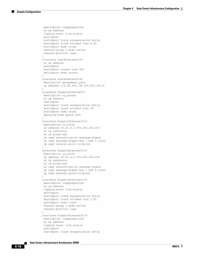
Chapter 4 Data Center Infrastructure ConfigurationSample Configurations
description toaggregation2 no ip address logging event link-status switchport switchport trunk encapsulation dot1q switchport trunk allowed vlan 3,20 switchport mode trunk channel-group 2 mode active channel-protocol lacp!interface FastEthernet8/47 no ip address switchport switchport access vlan 802 switchport mode access!interface FastEthernet8/48 description management_port ip address 172.26.200.136 255.255.255.0!interface GigabitEthernet9/1 description to_access no ip address switchport switchport trunk encapsulation dot1q switchport trunk allowed vlan 20 switchport mode trunk spanning-tree guard root!interface GigabitEthernet9/13 description to_core1 ip address 10.21.0.1 255.255.255.252 no ip redirects no ip proxy-arp ip ospf authentication message-digest ip ospf message-digest-key 1 md5 0 cisco ip ospf network point-to-point!interface GigabitEthernet9/14 description to_core2 ip address 10.21.0.5 255.255.255.252 no ip redirects no ip proxy-arp ip ospf authentication message-digest ip ospf message-digest-key 1 md5 0 cisco ip ospf network point-to-point!interface GigabitEthernet9/15 description toaggregation2 no ip address logging event link-status switchport switchport trunk encapsulation dot1q switchport trunk allowed vlan 3,20 switchport mode trunk channel-group 2 mode active channel-protocol lacp!interface GigabitEthernet9/16 description toaggregation2 no ip address logging event link-status switchport switchport trunk encapsulation dot1q
4-16Data Center: Infrastructure Architecture SRND
956513
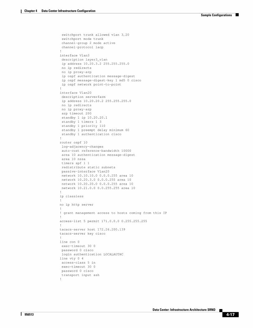
Chapter 4 Data Center Infrastructure ConfigurationSample Configurations
switchport trunk allowed vlan 3,20 switchport mode trunk channel-group 2 mode active channel-protocol lacp!interface Vlan3 description layer3_vlan ip address 10.20.3.2 255.255.255.0 no ip redirects no ip proxy-arp ip ospf authentication message-digest ip ospf message-digest-key 1 md5 0 cisco ip ospf network point-to-point!interface Vlan20 description serverfarm ip address 10.20.20.2 255.255.255.0 no ip redirects no ip proxy-arp arp timeout 200 standby 1 ip 10.20.20.1 standby 1 timers 1 3 standby 1 priority 110 standby 1 preempt delay minimum 60 standby 1 authentication cisco!router ospf 10 log-adjacency-changes auto-cost reference-bandwidth 10000 area 10 authentication message-digest area 10 nssa timers spf 1 1 redistribute static subnets passive-interface Vlan20 network 10.10.10.0 0.0.0.255 area 10 network 10.20.3.0 0.0.0.255 area 10 network 10.20.20.0 0.0.0.255 area 10 network 10.21.0.0 0.0.255.255 area 10!ip classless!no ip http server!! grant management access to hosts coming from this IP!access-list 5 permit 171.0.0.0 0.255.255.255!tacacs-server host 172.26.200.139tacacs-server key cisco!line con 0 exec-timeout 30 0 password 0 cisco login authentication LOCALAUTHCline vty 0 4 access-class 5 in exec-timeout 30 0 password 0 cisco transport input ssh!
4-17Data Center: Infrastructure Architecture SRND
956513
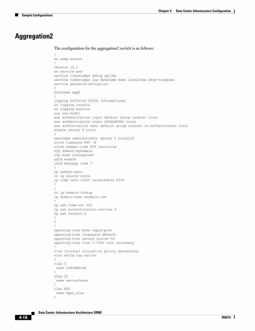
Chapter 4 Data Center Infrastructure ConfigurationSample Configurations
Aggregation2
The configuration for the aggregation2 switch is as follows:!no snmp-server!version 12.1no service padservice timestamps debug uptimeservice timestamps log datetime msec localtime show-timezoneservice password-encryption!hostname agg2!logging buffered 65536 informationalno logging consoleno logging monitoraaa new-modelaaa authentication login default group tacacs+ localaaa authentication login LOCALAUTHC localaaa authorization exec default group tacacs+ if-authenticated localenable secret 0 cisco!username administrator secret 0 cisco123clock timezone PST -8clock summer-time PDT recurringvtp domain mydomainvtp mode transparentudld enableudld message time 7!ip subnet-zerono ip source-routeip icmp rate-limit unreachable 2000!!no ip domain-lookupip domain-name example.com!ip ssh time-out 120ip ssh authentication-retries 3ip ssh version 2!!!spanning-tree mode rapid-pvstspanning-tree loopguard defaultspanning-tree extend system-idspanning-tree vlan 1-1000 root secondary!vlan internal allocation policy descendingvlan dot1q tag native !vlan 3 name L3RTRNEIGH!vlan 20 name serverfarms!vlan 802 name mgmt_vlan!
4-18Data Center: Infrastructure Architecture SRND
956513

Chapter 4 Data Center Infrastructure ConfigurationSample Configurations
!interface Loopback0 ip address 10.10.10.4 255.255.255.255!interface Null0 no ip unreachables!interface Port-channel2 no ip address switchport switchport trunk encapsulation dot1q switchport trunk allowed vlan 3,20 switchport mode trunk!interface GigabitEthernet1/1 description toaggregation1 no ip address logging event link-status switchport switchport trunk encapsulation dot1q switchport trunk allowed vlan 3,20 switchport mode trunk channel-group 2 mode passive channel-protocol lacp!interface GigabitEthernet1/2 description toaggregation1 no ip address logging event link-status switchport switchport trunk encapsulation dot1q switchport trunk allowed vlan 3,20 switchport mode trunk channel-group 2 mode passive channel-protocol lacp!interface FastEthernet8/47 description management_vlan no ip address switchport switchport access vlan 802 switchport mode access!interface FastEthernet8/48 description management_port ip address 172.26.200.132 255.255.255.0!interface GigabitEthernet9/1 description to_access no ip address switchport switchport trunk encapsulation dot1q switchport trunk allowed vlan 20 switchport mode trunk spanning-tree guard root!interface GigabitEthernet9/13 description to_core1 ip address 10.21.0.9 255.255.255.252 no ip redirects no ip proxy-arp ip ospf authentication message-digest ip ospf message-digest-key 1 md5 0 cisco ip ospf network point-to-point
4-19Data Center: Infrastructure Architecture SRND
956513
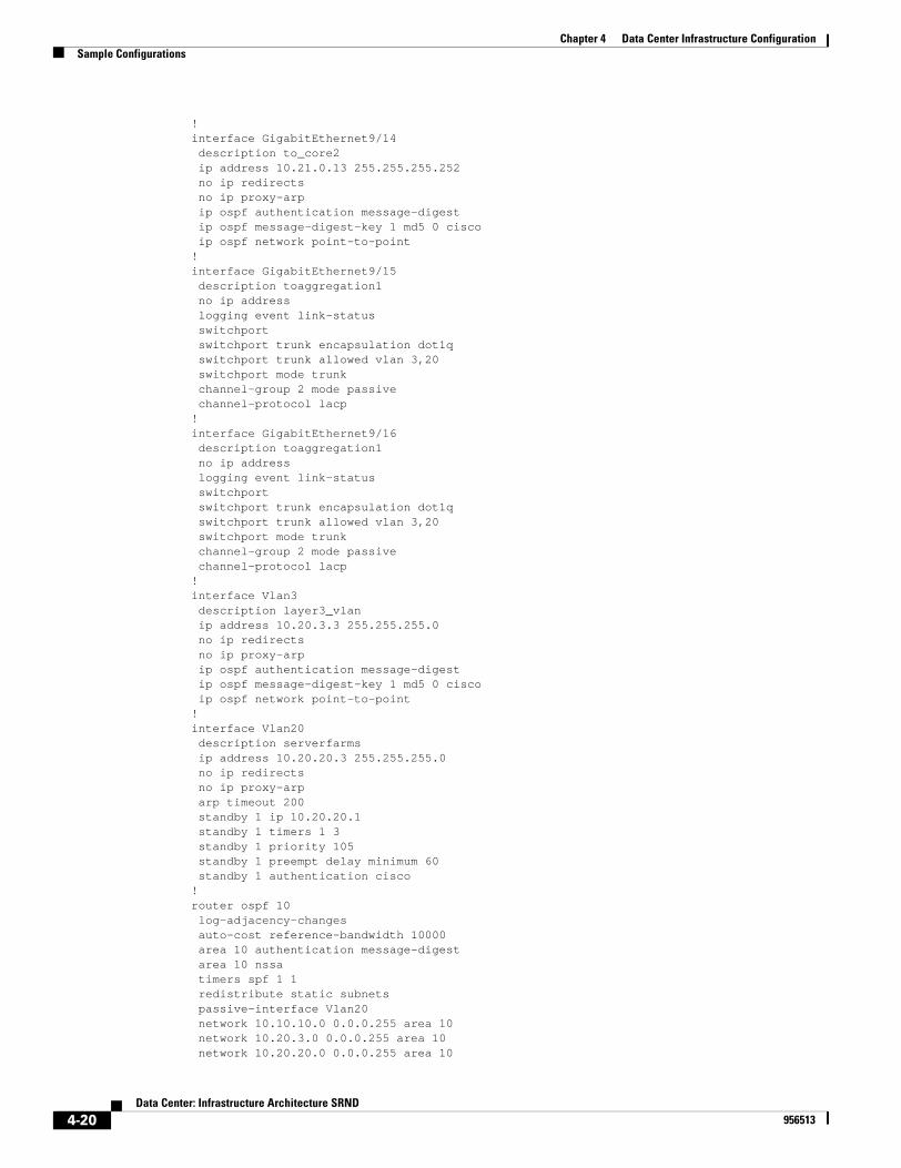
Chapter 4 Data Center Infrastructure ConfigurationSample Configurations
!interface GigabitEthernet9/14 description to_core2 ip address 10.21.0.13 255.255.255.252 no ip redirects no ip proxy-arp ip ospf authentication message-digest ip ospf message-digest-key 1 md5 0 cisco ip ospf network point-to-point!interface GigabitEthernet9/15 description toaggregation1 no ip address logging event link-status switchport switchport trunk encapsulation dot1q switchport trunk allowed vlan 3,20 switchport mode trunk channel-group 2 mode passive channel-protocol lacp!interface GigabitEthernet9/16 description toaggregation1 no ip address logging event link-status switchport switchport trunk encapsulation dot1q switchport trunk allowed vlan 3,20 switchport mode trunk channel-group 2 mode passive channel-protocol lacp!interface Vlan3 description layer3_vlan ip address 10.20.3.3 255.255.255.0 no ip redirects no ip proxy-arp ip ospf authentication message-digest ip ospf message-digest-key 1 md5 0 cisco ip ospf network point-to-point!interface Vlan20 description serverfarms ip address 10.20.20.3 255.255.255.0 no ip redirects no ip proxy-arp arp timeout 200 standby 1 ip 10.20.20.1 standby 1 timers 1 3 standby 1 priority 105 standby 1 preempt delay minimum 60 standby 1 authentication cisco!router ospf 10 log-adjacency-changes auto-cost reference-bandwidth 10000 area 10 authentication message-digest area 10 nssa timers spf 1 1 redistribute static subnets passive-interface Vlan20 network 10.10.10.0 0.0.0.255 area 10 network 10.20.3.0 0.0.0.255 area 10 network 10.20.20.0 0.0.0.255 area 10
4-20Data Center: Infrastructure Architecture SRND
956513

Chapter 4 Data Center Infrastructure ConfigurationSample Configurations
network 10.21.0.0 0.0.255.255 area 10!ip classless!no ip http server!! grant management access to hosts coming from this address!access-list 5 permit 171.0.0.0 0.255.255.255!tacacs-server host 172.26.200.139tacacs-server key cisco!line con 0 exec-timeout 30 0 password 0 cisco login authentication LOCALAUTHCline vty 0 4 access-class 5 in exec-timeout 30 0 password 0 cisco transport input ssh!
Access
The configuration for the access switch is as follows:
!no snmp-server!version 12.1service timestamps debug uptimeservice timestamps log uptimeservice password-encryption!hostname acc1!logging buffered 65536 informationalno logging consoleno logging monitoraaa new-modelaaa authentication login default group tacacs+ localaaa authentication login LOCALAUTHC localaaa authorization exec default group tacacs+ if-authenticated localenable secret 0 cisco!username administrator secret 0 cisco123vtp domain mydomainvtp mode transparentudld enableudld message time 7!ip subnet-zero!!no ip domain-lookupip domain-name example.com!
4-21Data Center: Infrastructure Architecture SRND
956513
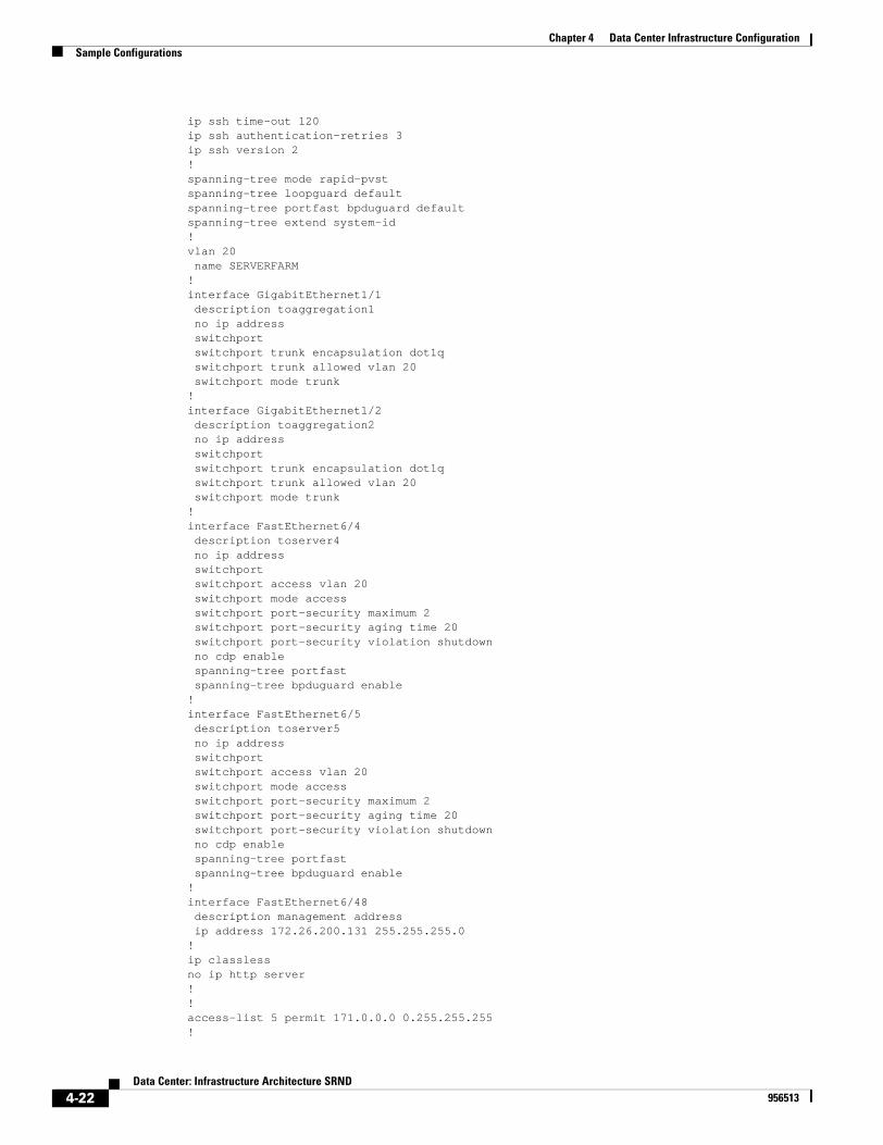
Chapter 4 Data Center Infrastructure ConfigurationSample Configurations
ip ssh time-out 120ip ssh authentication-retries 3ip ssh version 2!spanning-tree mode rapid-pvstspanning-tree loopguard defaultspanning-tree portfast bpduguard defaultspanning-tree extend system-id!vlan 20 name SERVERFARM!interface GigabitEthernet1/1 description toaggregation1 no ip address switchport switchport trunk encapsulation dot1q switchport trunk allowed vlan 20 switchport mode trunk!interface GigabitEthernet1/2 description toaggregation2 no ip address switchport switchport trunk encapsulation dot1q switchport trunk allowed vlan 20 switchport mode trunk!interface FastEthernet6/4 description toserver4 no ip address switchport switchport access vlan 20 switchport mode access switchport port-security maximum 2 switchport port-security aging time 20 switchport port-security violation shutdown no cdp enable spanning-tree portfast spanning-tree bpduguard enable!interface FastEthernet6/5 description toserver5 no ip address switchport switchport access vlan 20 switchport mode access switchport port-security maximum 2 switchport port-security aging time 20 switchport port-security violation shutdown no cdp enable spanning-tree portfast spanning-tree bpduguard enable!interface FastEthernet6/48 description management address ip address 172.26.200.131 255.255.255.0!ip classlessno ip http server!!access-list 5 permit 171.0.0.0 0.255.255.255!
4-22Data Center: Infrastructure Architecture SRND
956513

Chapter 4 Data Center Infrastructure ConfigurationSample Configurations
tacacs-server host 172.26.200.139tacacs-server key cisco!line con 0 exec-timeout 30 0 password 0 cisco login authentication LOCALAUTHCline vty 0 4 access-class 5 in exec-timeout 30 0 password 0 cisco transport input ssh!
4-23Data Center: Infrastructure Architecture SRND
956513

Chapter 4 Data Center Infrastructure ConfigurationSample Configurations
4-24Data Center: Infrastructure Architecture SRND
956513
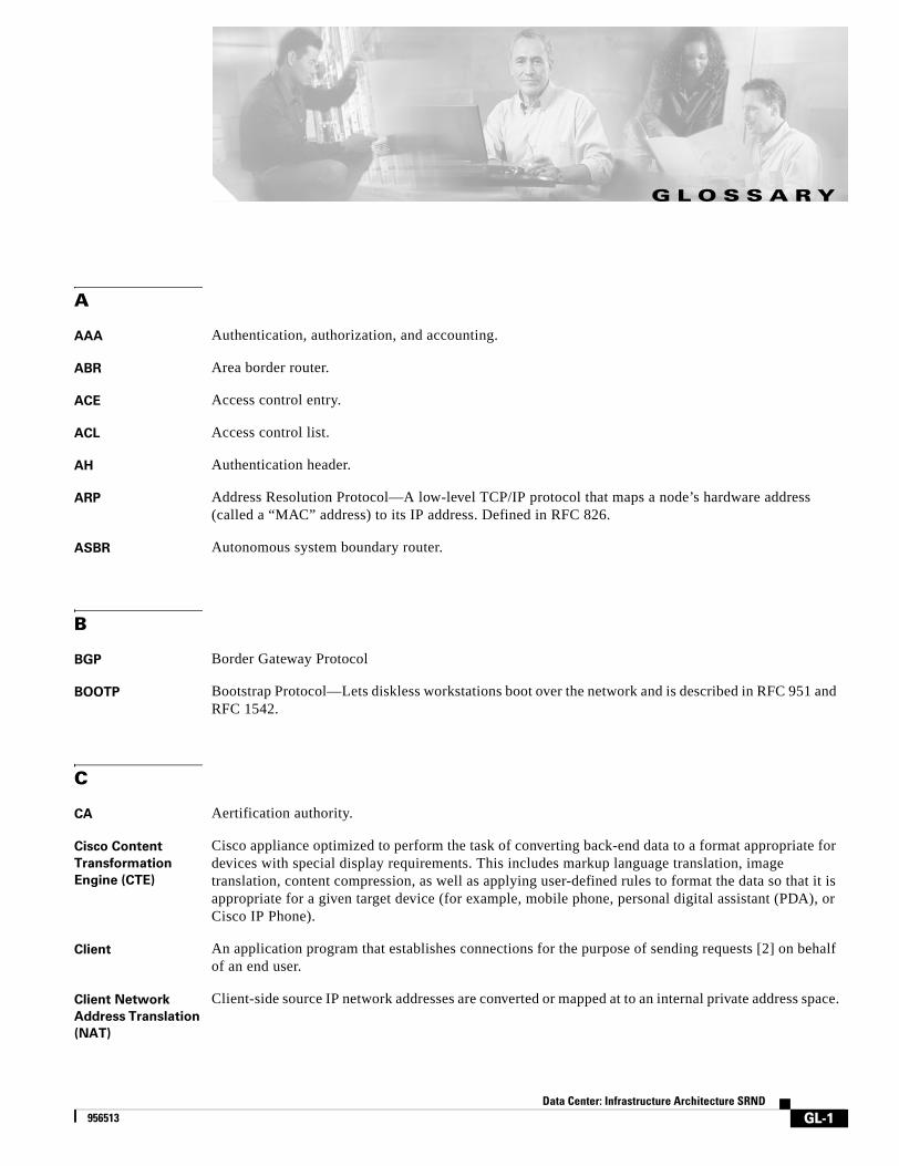
Data Cen956513
G L O S S A R Y
A
AAA Authentication, authorization, and accounting.
ABR Area border router.
ACE Access control entry.
ACL Access control list.
AH Authentication header.
ARP Address Resolution Protocol—A low-level TCP/IP protocol that maps a node’s hardware address (called a “MAC” address) to its IP address. Defined in RFC 826.
ASBR Autonomous system boundary router.
B
BGP Border Gateway Protocol
BOOTP Bootstrap Protocol—Lets diskless workstations boot over the network and is described in RFC 951 and RFC 1542.
C
CA Aertification authority.
Cisco Content
Transformation
Engine (CTE)
Cisco appliance optimized to perform the task of converting back-end data to a format appropriate for devices with special display requirements. This includes markup language translation, image translation, content compression, as well as applying user-defined rules to format the data so that it is appropriate for a given target device (for example, mobile phone, personal digital assistant (PDA), or Cisco IP Phone).
Client An application program that establishes connections for the purpose of sending requests [2] on behalf of an end user.
Client Network
Address Translation
(NAT)
Client-side source IP network addresses are converted or mapped at to an internal private address space.
GL-1ter: Infrastructure Architecture SRND

Glossary
Concurrent
Connections (CC)
The total number of single connections established through a device at a given time.
Connections per
second (CPS)
The number of single connection requests received during one second. Loading a single Web page could generate, and usually does, multiple connection requests.
Connection
Persistence
The ability to pipeline” multiple HTTP requests to the same TCP Connection. This method uses HTTP 1.1.
Cookie A message given to a WEb browser by a Web server or Cisco CSS 11000 CSS. The browser stores the message in a text file called cookie.txt. The message is then sent back to the server each time the browser makes a request to the URL associated with the cookie.
The main purpose of cookies is to identify users and possibly prepare customized Web pages for them. For example, instead of seeing just a generic welcome page, the user might see a welcome page with their name on it.
Cookie Active The load balancer inserts cookies in client packets. The cookies identify the server that will handle subsequent client requests.
Cookie Passive The server inserts cookies in the client packets. The load balancer reads the cookies in the responsive stream and creates a table entry containing the cookie and server ID.
Cookie Sticky The ability for a load balancing device to “stick” or create a persistent connection between a client and server based on cookie information located in the browser.
Content
Optimization
Engine (COE)
Solution targeted at solving some of the inherent problems with transmitting content over wireless networks. COE provides content and link optimization for Service Providers, Mobile Operators, and large Enterprises.
Content Engine based solution on the CE590 that compresses GIFs, JPGs, and text to lessen the data that will flow of the network. Also included is optimization of the TCP stack. Hooks have been added to allow a provider to add XML style sheets to the Cisco Content Engine, as well, to provide transcoding (or content adaptation) for multiple device support. Mobile Operators will require this type of solution to lessen the bandwidth requirements needed today for transmitting data over their wireless infrastructure.
Content Rule A hierarchal rule set containing individual rules that describe which content (for example, .html files) is accessible by visitors to the Web site, how the content is mirro4red, on which server the content resides, and how the CSS processes the request for content. Each rule set must have an owner.
Content Switching,
CS
A device that front-ends the servers and dynamically decides which back-end server services the client request. The CS makes the decision based on a multitude if Layer 3 through Layer 7 criteria that is “sniffed from the client request. See delayed binding
CPU Central processing unit.
CRL Certificate revocation list.
CTI Computer telephony integration.
CSM Content Switching Module
CSS Content Service Switch
GL-2Data Center: Infrastructure Architecture SRND
956513
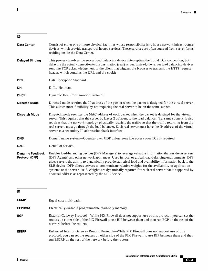
Glossary
D
Data Center Consist of either one or more physical facilities whose responsibility is to house network infrastructure devices, which provide transport of hosted services. These services are often sourced from server farms residing inside the Data Center.
Delayed Binding This process involves the server load balancing device intercepting the initial TCP connection, but delaying the actual connection to the destination (real) server. Instead, the server load balancing devices send the TCP acknowledgement to the client that triggers the browser to transmit the HTTP request header, which contains the URL and the cookie.
DES Data Encryption Standard.
DH Diffie-Hellman.
DHCP Dynamic Host Configuration Protocol.
Directed Mode Directed mode rewrites the IP address of the packet when the packet is designed for the virtual server. This allows more flexibility by not requiring the real server to be on the same subnet.
Dispatch Mode Dispatch mode rewrites the MAC address of each packet when the packet is destined for the virtual server. This requires that the server be Layer 2 adjacent to the load balancer (i.e. same subnet). It also requires that the network topology physically restricts the traffic so that the traffic returning from the real servers must go through the load balancer. Each real server must have the IP address of the virtual server as a secondary IP address/loopback interface.
DNS Domain name system—Operates over UDP unless zone file access over TCP is required.
DoS Denial of service.
Dynamic Feedback
Protocol (DFP)
Enables load-balancing devices (DFP Managers) to leverage valuable information that reside on servers (DFP Agents) and other network appliances. Used in local or global load-balancing environments, DFP gives servers the ability to dynamically provide statistical load and availability information back to the SLB device. DFP allows servers to communicate relative weights for the availability of application systems or the server itself. Weights are dynamically reported for each real server that is supported by a virtual address as represented by the SLB device.
E
ECMP Equal cost multi-path.
EEPROM Electrically erasable programmable read-only memory.
EGP Exterior Gateway Protocol—While PIX Firewall does not support use of this protocol, you can set the routers on either side of the PIX Firewall to use RIP between them and then run EGP on the rest of the network before the routers.
EIGRP Enhanced Interior Gateway Routing Protocol—While PIX Firewall does not support use of this protocol, you can set the routers on either side of the PIX Firewall to use RIP between them and then run EIGRP on the rest of the network before the routers.
GL-3Data Center: Infrastructure Architecture SRND
956513
Glossary
ESP Encapsulating Security Payload. Refer to RFC 1827 for more information.
Extensible Markup
Language
A language that allows developers to create customizable tags to aid in the definition, transmission, validation, and interpretation of data between applications.
F
Firewall Load
Balancing (FWLB)
For scalable firewall security, Cisco intelligently directs traffic across multiple firewalls, eliminating performance bottlenecks and single points of failure. Firewall load balancing eliminates system downtime that results when a firewall fails or becomes overloaded—breaking Internet connections and disrupting e-commerce purchases or other mission-critical transactions.
Flash Crowd Unpredictable, “event-driven” traffic that swamps servers and disrupts site services.
FTP File Transfer Protocol.
G
Global Server Load
Balancing (GSLB)
Load-balancing servers across multiple sites, allowing local servers to respond to not only incoming requests, but to remote servers as well. The Cisco CSS 11000 Content Services Switch supports GSLB through inter-switch exchanges or via a proximity database option.
H
H.323 A collection of protocols that allow the transmission of voice data over TCP/IP networks.
Health Checks Used by the server load balancing devices to check server state and availability based on standard application and network protocols and (depending on the server load balancing product) sometimes customized health check information.
Hosting Solutions
Engine (HSE)
Turnkey, hardware-based solution for e-business operations in Cisco-powered data centers. Provides: Fault and performance monitoring of Cisco hosting infrastructure and Layer 4-7 hosted services, Layer 4-7 service activation, such as taking Web servers in and out of service, Historical data reporting for all monitored devices/services, and Tiered user access model and customer view personalization.
HTTP Redirection The process by which Hypertext Transfer Protocol (HTTP) requests made by the Cisco Content Distribution Manager are redirected to a client “local” content engine. The request is then served from the content engine.
HSRP Hot-Standby Routing Protocol.
HTTPS HTTP over SSL.
Hypertext Transfer
Protocol (HTTP 1.0)
This version of HTTP requires a separate TCP connection for each HTTP request initiated. Because of this, a high amount of overhead is associated with the use of HTTP 1.0.
Hypertext Transfer
Protocol (HTTP 1.1)
This version provides persistent connection capability and allows multiple HTTP requests to be pipelined through a single TCP connection.
GL-4Data Center: Infrastructure Architecture SRND
956513
Glossary
I
IANA Internet Assigned Number Authority—Assigns all port and protocol numbers for use on the Internet.
ICMP Internet Control Message Protocol—This protocol is commonly used with the ping command. You can view ICMP traces through the PIX Firewall with the debug trace on command. Refer to RFC 792 for more information.
Internet Data Center
(IDC)
A large scale, often shared infrastructure, which provides managed hosting services to customers.
IFP Internet Filtering Protocol.
IGMP Internet Group Management Protocol.
IGRP Interior Gateway Routing Protocol.
IKE Internet Key Exchange.
IKMP Internet Key Management Protocol.
IOSSLB IOS Server Load Balancing
IP Internet Protocol.
IPSec IP Security Protocol efforts in the IETF (Internet Engineering Task Force).
ISAKMP Internet Security Association and Key Management Protocol.
ITU International Telecommunication Union.
L
Lightweight
Directory Access
Protocol (LDAP)
Protocol that provides access for management and browser applications that provide read/write interactive access to the X.500 Directory.
LSA link-state advertisement.
M
MD5 Message Digest 5—An encryption standard for encrypting VPN packets.
MIB Management information base—The database used with SNMP.
MTU Maximum transmission unit—The maximum number of bytes in a packet that can flow efficiently across the network with best response time. For Ethernet, the default MTU is 1500 bytes, but each network can have different values, with serial connections having the smallest values. The MTU is described in RFC 1191.
GL-5Data Center: Infrastructure Architecture SRND
956513
Glossary
N
Network Address
Translation (NAT)
Provides the ability to map hidden “internal” network IP addresses to routable “external” issued IP addresses. The internal IP addresses are typically drawn from the private address spaces defined in RFC 1918.
NAT Peering Cisco CSS11000 Series Switches use NAT Peering to direct requests to the best site with the requested content based on URL or file type, geographic proximity and server/network loads, avoiding the limitations of Domain Name System (DNS)-based site selection and the overhead of HTTP redirect. NAT peering acts as a “triangulation protocol” allowing the response to be directly delivered to the user over the shortest Internet path.
NBMA Nonbroadcast multiaccess.
NetBIOS Network Basic Input Output System—An application programming interface (API) that provides special functions for PCs in local-area networks (LANs).
NIC Network Information Center.
NNTP Network News Transfer Protocol—News reader service.
NOS Network operating system.
NSSA Not so stubby area.
NTP Network Time Protocol—Set system clocks via the network.
NVT Network virtual terminal.
O
OSPF Open Shortest Path First protocol.
Origin Web Server Core of Content Networking. Base from where web services are sourced.
P
PAT Port address translation.
PFS perfect forward secrecy.
PIM Protocol Independent Multicast.
PIM-SM PIM sparse mode.
GL-6Data Center: Infrastructure Architecture SRND
956513
Glossary
PIX Private Internet Exchange.
PKI Public Key Infrastructure.
R
RADIUS Remote authentication dial-in user service—User authentication server specified with the aaa-server command.
RAS The registration, admission, and status protocol. Provided with H.323 support.
RC4 RC4 is stream cipher designed by Rivest for RSA Data Security, Inc. It is a variable key-size stream cipher with byte-oriented operations. The algorithm is based on the use of a random permutation.
RFC Request for comment—RFCs are the defacto standards of networking protocols.
RHI Route health injection.
RIP Routing Information Protocol.
RPC Remote procedure call.
RSA Rivest, Shamir, and Adelman. RSA is the trade name for RSA Data Security, Inc.
RTP Real-Time Transport Protocol.
RTCP RTP Control Protocol.
RTSP Real Time Streaming Protocol.
S
SA Security association.
SCCP Simple (Skinny) Client Control Protocol.
Secure Content
Accelerator (SCA)
The Cisco 11000 series Secure Content Accelerator (SCA 11000) is an appliance-based solution that increases the number of secure connections supported by a Web site by offloading the processor-intensive tasks related to securing traffic with SSL. Moving the SSL security processing to the SCA simplifies security management and allows Web servers to process more requests for content and handle more e-transactions.
Secure Sockets
Layer (SSL)
A security protocol that provides communications privacy over the Internet. The protocol allows client/server applications to communicate in a way that is designed to prevent eavesdropping, tampering, or message forgery.
Server NAT The IP address of the real server on the internal network is converted or mapped to a client side network IP address. Therefore, the real server’s IP address is never advertised to the client-side network.
GL-7Data Center: Infrastructure Architecture SRND
956513
Glossary
Session Loosely defined as series of HTTP and TCP connections to a site, which constitute a single client’s visit.
Session Persistence The ability for server load balancing device to “stick” a requester (client) to a particular server using various methods including: Source IP sticky, Cookie Sticky, SSL Sticky, HTTP Redirection Sticky.
Session State Multiple connections that belong to the same session for which session state is kept.
SLB Data Path Catalyst 6000 switching bus path followed by control SLB packets.
SLB Engine The CISCO IOS®SLB Software process running at the SLB device. It controls all of Load Balancing capabilities and it may use ASIC to assist certain specific tasks.
SLB Device Switch or router running Cisco IOS SLB. Currently Catalyst 6000, 7200 router, and Catalyst 4840.
SMR Stub multicast routing.
SMTP Simple Mail Transfer Protocol—Mail service. The fixup protocol smtp command enables the Mail Guard feature. The PIX Firewall Mail Guard feature is compliant with both the RFC 1651 EHLO and RFC 821 section 4.5.1 commands.
SNMP Simple Network Management Protocol—Set attributes with the snmp-server command.
SPI Security Parameter Index—A number which, together with a destination IP address and security protocol, uniquely identifies a particular security association.
Source IP Sticky The ability for a load balancing device to “stick” or create a persistent connection between a client and server based on the client source IP address.
Source of Authority
(SOA)
The primary DNS server for a particular domain.
SSH Secure Shell.
SSL Optimization Content-switching service wherein SSL sessions are terminated prior to the server in order to enable application of content rules to encrypted traffic. Utilization of this service enhances performance without sacrificing security.
SSL Sticky The ability for a load balancing device to “stick” or create a persistent connection between a client and server based on the SSL session id of the client.
Stateful Failover Ensures that connection “state” information is maintained upon failover from one device to another. Session transaction information is also maintained and copied between devices to alleviate any downtime from occurring with websites and services.
Stateless Failover Maintains both device and link failure status and provides failover notifications if one of these fails. However, unlike stateful failover, stateless failover does not copy session state information from one device to another upon failure. Therefore, any “state” information between the client and server must be retransmitted.
Storage Array (SA) Cisco storage arrays provide storage expansion to Cisco’s Content Delivery Network products. Two models are offered: Cisco Storage Array 6 (108 GB) and Cisco Storage Array 12 (216 GB).
SYN Synchronize sequence numbers flag in the TCP header.
GL-8Data Center: Infrastructure Architecture SRND
956513
Glossary
T
TACACS+ Terminal access controller access control system plus.
Time to Live (TTL) The time to live a packet has to transeverse the network. Each hop that a packet takes thoughtout the network, decrements the TTL value until it is eventually dropped. Keeps the packet from bouncing around the network. For mulitcast, the TTL should never be greater than 7, for routing the TTL should never greater than 15.
TCP Transmission Control Protocol. Refer to RFC 793 for more information.
TCP Control Packets TCP packets with certain flags turned on that indicate a particular action is to take place.SYN: Connection request indicationACK: AcknowledgementSYN/ACK: Connection request acknowledgement indicationFIN: Connection Teardown indicationFIN/ACK: Connection Teardown Acknowledgement indicationRST: Connection reset indication
TFTP Trivial File Transfer Protocol.
Triple DES Triple Data Encryption Standard. Also known as 3DES.
Transport Layer
Security
A protocol providing communications privacy over the Internet. The protocol allows client/server applications to communicate in a way that prevents eavesdropping, tampering, or message forgery. TLS is the successor to Secure Sockets Layer (SSL).
U
uauth User authentication.
UDP User Datagram Protocol.
Universal Resource
Locator (URL)
Standardized addressing scheme for accessing hypertext documents and other services using a browser. URLs are contained within the User Data field and point to specific Web pages and content.
URL Hashing This feature is an additional predictor for Layer 7 connections in which the real server is chosen using a hash value based on the URL. This hash value is computed on the entire URL or on a portion of it.
V
Virtual Server Logical server in a content switch used to a service offered by multiple Real Servers to a single IP address, protocol and port number used by clients to access the specific service.
VLAN virtual LAN.
VoIP Voice over IP.
GL-9Data Center: Infrastructure Architecture SRND
956513

Glossary
W
WWW World wide web.
GL-10Data Center: Infrastructure Architecture SRND
956513
Data Cente956513
I N D E X
Numerics
10 Gigabit Ethernet 1-3, 1-7
802.1 1-15, 2-14
A
AAA 1-19, 4-1
ABRs, placement 2-3
access layer
Catalyst 6500 hardware 1-7
described 1-10
Layer 2 1-15
access ports, BPDU guard 1-16
adapter fault tolerance 1-13, 3-5, 3-10
adaptive load balancing 3-5, 3-12
Advanced Networking Services adapter 3-8
Advanced Peer-to-Peer Networking 3-20
advertise default routes 2-7
aggregation layer
described 1-10
Layer 3 protocols 1-16
aggregation routers 2-3
aggregation switches
configuration 2-6
application monitoring 1-12
architecture, illustrated 1-2
area border routers
see ABRs
ARP table
aging entries 2-23
stability 3-12
sticky entries 3-20
ASBR
Internet data center 2-3
asymmetric traffic patterns 2-23
auditing 1-19
Authentication Authorization and Accounting
see AAA
autonomous system border routers
see ASBR
availability, service classes 1-12
B
BackboneFast 1-15
bandwidth, scaling 1-18
bottlenecks server-to-server 1-12
BPDU Guard
effective with PortFast 3-28
high availability 3-28
preventing DoS attacks 2-20
BPDUs
described 1-16
spanning tree 2-14
bridge priorities 4-7
bridging loops
preventing 3-28
C
CAM table 2-19
Cat 5 cabling 1-7
Catalyst 3750 1-8
Catalyst 4500 1-8
Catalyst 6500
IN-1r: Infrastructure Architecture SRND
Index
6506 1-8
6509 1-4
6513 1-4
form factors 1-4
GMRP configuration 3-11
rack units 1-4
service modules 1-3
Catalyst OS
HA 2-9
SSHv2 1-19
CEF load balancing 1-18
channeling 3-13
Channel Interface Processor
see CIP/CPA
CIP/CPA
Layer 3 mainframe connectivity 1-17
Cisco IOS software releases recommended 1-9
Cisco Works 2000 Resource Manager Essentials
see RME
client NAT 1-12
community VLANs 3-19
configuration management 1-19
Content Accelerator 2 1-5
content addressable memory
see CAM table
Content Service Module
see CSM
Content Service Switch
see CSS
content switches
bridge mode 4-8
convergence
Layer 2 1-16
Layer 3 2-3
minimizing 2-6
RPVST+ and MST 2-10
spanning tree 2-14
copper cable for Fast Ethernet 1-7
core layer, described 1-9
IN-2Data Center: Infrastructure Architecture SRND
Cross Coupling Facility 3-24
crypto key 4-2
CSM 1-3
performance 1-6
throughput 1-19
CSS
11500 SSL decryption module 1-5
described 1-5
D
data confidentiality 1-18
Data Link Switching 3-20
debug 4-3
default gateway
assigning 2-21
boundary between Layer 2 and Layer 3 2-11
placement options 1-17
placement options illustrated 2-22
placement with load balancing 1-12
default routes
multiple 3-15
demilitarized zone 2-3
Denial of Service
see DoS attacks
deployment modes
dual-attached servers 3-8
Direct Server Return 1-12
Distributed DVIPA 3-26
DNS
multihoming 3-15
Domain Name System
see DNS
DoS attacks, preventing 2-20
dual-attached mainframe 3-22
dual-attached servers
deployment modes 3-8
described 1-16
high availability 3-4
956513
Index
illustrated 3-5
duplex settings 4-12
DVIPA 3-25
dynamically assigned IP addresses
see DHCP
dynamic LACP 3-14
dynamic routing protocols 3-15
Dynamic Trunking Protocol 4-11
dynamic VIPA
see DVIPA
E
edge ports
defined 2-10
PortFast and TrunkFast 3-28
edge routers 2-3
EIGRP
illustrated 2-7
MD5 authentication 2-8
not supported GL-3
Enhanced Interior Gateway Routing Protocol
See EIGRP
Enterprise Extenders 3-20
Enterprise System Connections
see ESCON
ESCON
attachment option 3-21
illustrated 3-22
Layer 3 connections 1-17
with Sysplex 3-6
EtherChannels 1-18
Ethernet
configuration 4-12
types of 1-7
extended VLANs
VLANs
extended 4-5
956513
F
fabric-connected linecards 1-19
fabric module
see SFM2
fabric switching 1-18
failure, points of 3-2
Fast EtherChannel 3-14
FastEthernet
configuration 4-12
fault tolerance 3-9
FCS errors 3-27, 4-12
fiber cable for Fast Ethernet 1-7
filtering routes 2-8
firewalls
Layer 2 design 2-11
Firewall Service Module
see FWSM
flapping
NIC cards 4-13
PortFast and TrunkFast to prevent 2-17
preventing 4-13
protection against 2-5
flooding
security attack 1-16
full-duplex 1-16, 3-27
FWSM
performance 1-6
server farms, protecting 1-11
throughput 1-19
G
GARP 3-11
Gateway Load Balancing Protocol
see GLBP
gateway redundancy protocols 2-22
GBICs 1-5
Generic Attribute Registration Protocol
IN-3Data Center: Infrastructure Architecture SRND

Index
see GARP
Gigabit EtherChannel 3-14
Gigabit Ethernet
configuration 4-12
GLBP, not supported 1-17
GMRP 3-11
H
HA 2-9
half-duplex 3-27
hardware configuration 1-4
hardware recommendations 1-3
hello and dead interval 2-6
high availability
dual-attached servers 3-4
NIC teaming 3-4
server farms 1-11
spanning tree 3-27
high performance routing 3-20
holdtime, OSPF 2-6
Hot Standby Routing Protocol
see HSRP
HSRP 2-22
configuration 4-8
default gateway availability 1-17
load balancing 3-4
prorities 2-23
without load balancing 1-12
HTTP requests
with TN3270 1-17
hub-and-spoke topology 2-2
I
IDS
4250 3-17
devices 1-18
IN-4Data Center: Infrastructure Architecture SRND
multi-homing 3-17
sensors 1-5
IDSM
performance 1-6
image management 1-20
Incremental Device Update v5.0 1-20
infrastructure
defined 1-1
illustrated 1-2
Intel PROSet Software 3-8
Internal Spanning Tree
see IST
Internet data center, illustrated 2-3
interoperability
Rapid PVST+ 1-15
interprocess communication 1-13
interrupt coalescing 3-5
intranet data center
illustrated 2-1
Intrusion Detection Service Module
see IDSM
inventory management 1-20
IOS Stateful SwitchOver
see SSO
isolated VLANs 3-19
IST 2-15
J
jumbo frames 1-8
L
LACP 3-14
late collisions 3-27, 4-12
Layer 2
design 2-10
loops, preventing 2-14
956513

Index
security 2-19
Layer 3
convergence 2-3
design illustrated 2-1
multihoming 3-14
ports 2-11
protocols 1-16
security 2-8
segregation 2-11
Layer 4 security services 1-18
link aggregation 3-13
link failures 3-9
link-state advertisement
see LSA
Linux
dynamic routing protocols 3-15
load balancing
CEF 1-18
default gateway placement 1-12
HSRP 3-4
Layer 2 design 2-11
NIC teaming 3-18
server farms 3-4
servers 1-12
service modules 1-3
VLAN-aware 1-14
local database 4-1
logging 4-3
Logical Partitions
see LPARs
logical segregation, illustrated 1-14
logical topology
Internet data center 2-3
intranet data center 2-1
logical units 3-21
loop-free designs 2-18, 3-27
LoopGuard
configuration 4-7
designing 2-14
956513
recommended 1-15
with UDLD 2-15
LPARs 1-17, 3-22, 3-23
failure 3-3
LSAs 2-4
LU-to-LU sessions 3-21
M
MAC addresses
assigning to virtual adapter 3-12
multi-homed servers 3-29
port security 2-20
security 3-17
MAC address reduction 4-5
MAC address table 3-27
MAC flooding
security attack 1-16, 2-19
mainframes
attaching with OSAs 1-3
attachment options, illustrated 3-22
high availaiblity 3-21
hosting IP-based applications 3-21
Layer 3 protocols 1-17
OSPF 3-23
points of failure 3-3
Sysplex 3-24
maximum performance 1-19
MD5 authentication 1-17, 2-8
mismatches
duplex settings 4-12
Ethernet 3-27
MSFC
aggregation layer 1-16
performance considerations 1-19
MST
configuration 4-7
defined 2-14
Layer 2 design 2-10, 2-15
IN-5Data Center: Infrastructure Architecture SRND
Index
scaling with VLANs 2-13
multihoming
Layer 3 3-14
multilayer architecture, illustrated 1-2
Multilayer Switching Feature Card
see MSFC
multiple default routes 3-15
Multiple Instance STP
see MST
multiple NIC cards 3-5
N
NAM 1-3
NetBIOS 3-15
network analysis devices 1-18
Network Analysis Module
see NAM
network fault tolerance 3-11
network interface card
see NIC
network management 1-19
configuration 4-1
NIC teaming 3-4
non-repudiation 1-18
Not-So-Stubby Areas
see NSSAs
NSSAs
redistributing static routes 2-5
O
optical service adapters
see OSAs
OSAs 3-25
for attaching mainframes 1-3
recovery from failure 3-3
OSPF
IN-6Data Center: Infrastructure Architecture SRND
areas 2-4
authentication 2-6
holdtime 2-6
illustrated 2-5
LSA types 2-5
mainframes 1-17, 3-23
MD5 authentication 2-8
route cost 2-6
stub areas 2-4
summarization 2-4
with LPARs 3-23
oversubscription 1-7
P
passwords 4-1
PCI-X 3-5
performance, maximum 1-19
physical segregation 1-14
physical topology
Internet data center 2-3
intranet data center 2-1
physical units 3-21
PIX Firewalls 1-5
points of failure
mainframes 3-3
server farm 3-2
point-to-point links 2-7
port aggregation 3-6
port density 1-3
PortFast
described 1-16
enabling 4-13
high availability 3-28
illustrated 2-18
Layer 2 design 2-10
using 2-17
ports
duplex settings 3-27
956513
Index
speed and duplex settings 4-12
port security 2-20, 3-17, 4-13
primary root switch 1-16
primary VLANs 3-19
priorities
bridges 4-7
HSRP and spanning tree 2-23
Private VLANs
see PVLANs
probe responses 3-9
PVLANs 3-19
Q
QoS 1-18
R
rack space utilization, improving 1-6
rack units, used by Catalyst 6500 models 1-4
RADIUS 4-1
Rapid Per VLAN Spanning Tree Plus
see RPVST+
Rapid PVST+ 3-27
configuration 4-6
Layer 2 design 2-10, 2-15
recommended 1-15
scaling with VLANs 2-13
Rapid Transport Protocol 3-20
recommendations
Cisco IOS software releases 1-9
hardware and software 1-3
redundancy
supervisors 2-9
redundant links 3-27
Remote SPAN 1-18, 3-17
resilient server farms 1-13
restrict option
956513
not recommended 4-13
port security 3-17
reverse proxy caching 1-3
RME 1-20
Root bridge
priority 4-7
Root Guard 2-20
root switches
primary and secondary 1-16
route cost 2-6
Route Processor Redundancy
see RPR+
RPR+ 2-9
with VLANs 4-5
S
scaling bandwidth 1-18
secondary root bridge
priority 4-7
secondary root switches 1-16
Secure Shell
see SSH
Secure Sockets Layer
see SSL
security
data center 1-18
Layer 2 2-19
Layer 2 attacks 1-16
Layer 3 2-8
Layer 4 1-18
MAC flooding 2-19
OSPF authentication 2-6
port 1-16, 2-20, 3-17, 4-13
service modules 1-3
technologies 1-18
VLAN hopping 2-19
VLANs 2-13
segregation
IN-7Data Center: Infrastructure Architecture SRND
Index
between tiers 1-13
logical 1-14
physical 1-14
server farms 2-12
server farms
high availability 1-12
logical segregation 1-14
multi-tier 1-13
physical segregation 1-14
points of failure 3-2
segregation 2-12
types of servers 1-12
servers
port configuration 3-29
server-to-server traffic 1-15, 1-19
service appliances
segregating server farms 1-14
service applicances
described 1-5
service classes 1-13
service modules
advantages 1-5
fabric attached 1-19
load balancing and security 1-3
segregating server farms 1-14
supported by Catalyst 6500 1-3
service switches 1-10
session persistence 1-12
SFM2 with Sup2 1-4
shutdown 4-13
SNMP
disabling 4-3
software management 1-19
software recommendations 1-3
spanning tree
high availability 3-27
priorities 2-23
scaling with VLANs 2-13
vulnerabilities 2-20
IN-8Data Center: Infrastructure Architecture SRND
speed settings 4-12
SPF delay 2-6
SSH
for network management 1-19
version 4-2
SSL offloading devices 1-18
SSL Service Module
see SSLSM
SSLSM
performance 1-6
SSO 2-9
stability
PortFast 2-17
static LACP 3-14
static routing
mainframes 1-17
server farms 1-17
static VIPAs 3-26
sticky ARP entries 3-19
summarization
protects against flapping 2-5
Sup720
fabric 1-19
integrated fabric 1-4
upgrading from Sup2 1-5
Supervisor 2
see Sup2
Supervisor 3 1-8
supervisors
redundant 2-9
SVI 4-8
switched VLAN interface
see SVI
switch fault tolerance 1-13, 3-4, 3-11
SYN COOKIEs 1-18
syslog servers 1-19, 4-3
Sysplex 3-3, 3-24
virtualizing mainframes 3-6
System Network Architecture 3-20
956513
Index
System Services Control Point 3-21
T
TACACS 4-1
TCNs 3-27
TCP session loss, preventing 3-12
three-tier design 2-10
throughput, comparing Sup2 and Sup720 1-4
TN3270 1-17, 3-20
topologies
hub and spoke 2-2
Internet data center 2-3
intranet data center 2-1
totally stubby area 2-5
configuration 2-6
TrunkFast 2-10
illustrated 2-18
using 2-17
trunk mode 4-11
trunks
configuration 4-10
two-tier design 2-10
U
UDLD
configuration 4-8
described 1-15
designing 2-16
unicast Reverse Path Forwarding
see uRPF
Unidirectional Link Detection
see UDLD
Unix
dynamic routing protocols 3-15
upgrading to Sup720 1-5
UplinkFast 1-15
956513
uRPF
mainframes 1-17
usernames 4-1
V
VACL capture 1-18
VIPAs
recovering from LPAR failure 3-3
virtual adapters 3-9
Virtual IP Address
see VIPA
virtual machines
see VMs
virtual network adapters 3-18
Virtual Router Redundancy Protocol
see VRRP
Virtual Trunking Protocol
see VTP
VLAN-aware
load balancing 1-14
service modules 1-6
VLAN hopping 2-19
VLANs
configuration 4-4
database configuration mode, not recommended 4-5
determining number required 1-15
hello and dead interval 2-6
interface configuration 2-8
private 3-19
scalability 2-13
security 2-13, 2-19
segregating tiers 1-13
server farm segregation 2-12
VMs 1-17, 3-22
VRRP, not supported 1-17
VTP
configuration 4-4
described 2-14
IN-9Data Center: Infrastructure Architecture SRND
Index
transparent mode 2-14
VTY line 4-2
W
web-based applications 1-13
WINS 3-15
WorkLoad Manager 3-6
IN-10Data Center: Infrastructure Architecture SRND
956513
Recommended