Image-Based Pose Estimation for 3-D Modelingin Rapid, Hand-Held Motion
§Institute of Robotics and MechatronicsGerman Aerospace Center (DLR)
D-82234 Wessling, [email protected]
‡Department of InformaticsTechnische Universitat Munchen
D-85748 Garching, [email protected]
Klaus H. Strobl,§ Elmar Mair,‡ and Gerd Hirzinger§‡
Abstract— This work aims at accurate estimation of the poseof a close-range 3-D modeling device in real-time, at high-rate,and solely from its own images. In doing so, we replace externalpositioning systems that constrain the system in size, mobility,accuracy, and cost. At close range, accurate pose tracking fromimage features is hard because feature projections do not onlydrift in the face of rotation but also in the face of translation.Large, unknown feature drifts may impede real-time featuretracking and subsequent pose estimation—especially with con-current operation of other 3-D sensors on the same computer.The problem is solved in Ref. [1] by the partial integrationof readings from a backing inertial measurement unit (IMU).In this work we avoid using an IMU by improved featurematching: full utilization of the current state estimation (in-cluding structure) during feature matching enables decisivemodifications of the matching parameters for more efficienttracking—we hereby follow the Active Matching paradigm.
I. INTRODUCTIONIn Ref. [1] we presented the self-referenced DLR 3D-
Modeler, which is a 3-D modeling device for close-rangeapplications combining complementary sensors in a compact,generic way. A single 3-D modeling device is however rarelycapable of creating complete 3-D models of a scene since thegeometrical information gathered from a single vantage pointis naturally limited. Multiple views (or multiple sensors)are usually required to subsequently merge data to a single,complete 3-D model. The prevalent approach is to move asingle sensor around the scene while concurrently measuringits position and orientation (pose), thereby registering mul-tiple views—possibly in real-time. A wide range of externalreference systems are commonly deployed for this purpose.These traditional options are however extremely limitingsince they constrain the system in size, mobility, accuracy,and cost. In the aforementioned publication we demonstratedfor the first time a hand-held 3-D modeling device for close-range applications that localizes itself passively from its ownimages in real-time and at high-rate.
The latter development required however support froman inertial measuring unit (IMU), synchronized and rigidlyattached to the device, in order to still keep track of pose inthe case of highly dynamic motion (e.g. hand-held). Thisis because, at close range, projections do not only driftin the face of rotation but they also drift in the face oftranslation—at far range translational effects are negligible.
* This work was performed during the first author’s research stay in Dr.Andrew Davison’s group at Imperial College London. We are deeply gratefulto him as well as to his students Dr. Margarita Chli and Mr. Ankur Handa.
Moreover, in our particular application both effects arepotentially of similar size and may add up to drifts beyondthe capabilities of well-established tracking algorithms basedon feature matching.1 In Ref. [1] we bring forward a novel,hybrid feature drift prediction method that combines transla-tional motion propagation with the rotational readings of anIMU. The method is easy to implement and allows for robusttracking with very high motion bandwidth. In this sequelwork we aim at a tracking algorithm capable of handlinglarger projection drifts at high-rate without the use of anIMU, while concurrently digitizing the scene on the samecomputer, in real-time.
A. Active Vision
An active vision system is defined by Aloimonos in Ref.[2] as “a system able to manipulate its visual parameters ina controlled manner in order to extract useful data about thescene in space and time that would allow it to best performa set of tasks.” This is in contrast to general vision systemsthat aim at “a complete and accurate representation of thescene” [3] as active vision calls for partial perception—subject to the task at hand. Note that this subordinationalready suggests a top-down, feedback approach to vision.The classic example for active vision systems is humansand animals that evolved to active vision to narrow downperception to significant parts of the scene, which clearlyyields an advantage in the face of limited resources.2 Further-more the purposive (or animated) vision paradigm includesthe decision-taking process on how to manipulate the visualparameters, e.g. “where to look next? ” [2], [4].
Active vision systems in robotics were predominantlydeveloped concerning view direction control (gaze control)of cameras e.g. mounted on mobile robots [5]–[7]. Thesewere primarily motivated by navigational tasks like self-localization or obstacle avoidance rather than by real-timecomputational constraints. The variable visual parameterscomprise camera orientation and potentially the robot’s ownmotion.
1 Image features are salient areas of the image that are assumed to corres-pond to locally planar, textured patches in 3-D. Since they are measurableprojections of the state of the system, they can enable pose tracking.Features are an effective tool for tracking if search regions are kept small.
2 Some persons with mental disorders (e.g. savant syndrome by StephenWiltshire MBE) do feature the talent of virtually limitless visual memory,but this is invariably in combination with cognitive deficits.
2011 IEEE International Conference on Robotics and AutomationShanghai International Conference CenterMay 9-13, 2011, Shanghai, China
978-1-61284-380-3/11/$26.00 ©2011 IEEE 2593
In the context of vision-based sequential localization andmapping (visual SLAM) [8], Davison in Ref. [9] noted thatSLAM is an intrinsically passive problem separate fromcamera motion. He however claimed that we still can benefitof active, purposive vision for improved efficiency of visualSLAM by extending the scope of the aforementioned visualparameters to image processing itself—instead of consider-ing it a detached, self-contained task. His method is coinedActive Matching (AM) and basically puts image processinginto the loop of SLAM in a statistically optimal way [9]–[11].In this work we present a variation to AM tailored to our3-D modeling application that aims at particularly efficienttracking with very high motion bandwidth.
B. Related Work
Visual SLAM approaches face computational issues eitherin the long run (e.g. due to map size) or on a frame by framebasis (because of high number of features or rapid motion).The latter case corresponds to our current problem. A fewrecent (monocular) approaches address it:• Active Matching achieves a lower computational bur-
den using feature projection priors dynamically to guidea feature by feature matching search. In this work weshall adapt this approach (described in Section III)to our particular ego-motion estimation algorithm.
• Parallel Tracking and Mapping (PTAM) by Klein andMurray in Refs. [12], [13] is similar to our approachin many aspects. PTAM computationally decouplesmapping from tracking and relative pose estimation,which enables lax mapping and exhaustive trackingrespectively. In addition, they achieve a remarkable levelof robustness towards rapid camera motion by the useof FAST features [14] to identify potential matches andby an extensive pyramidal representation of images.
• 1-Point RANSAC approaches e.g. Refs. [15], [16]utilize single-point motion hypotheses to constrain ex-pected projection regions of the rest of the featuresiteratively, in the context of RANSAC. At first this iscarried out using constrained motion models; after thatassumptions are relaxed.
• Accelerated, descriptor-based approaches in Refs.[17]–[19] employ through feature descriptors. Theseallow for robust tracking and are usually intended tooffline operation. The authors manage to condition themto the available information on the state (e.g. decidingon the relevant scales) so that their use just becomespossible in real-time. The use of accelerated hardwarecomputing will surely boost these approaches, whichare still computationally very expensive.
In the course of this work these approaches are beingindividually addressed on their adequacy concerning scarcityof resources by concurrent operation with 3-D modeling.
The remainder of this article is as follows: In Section IIwe recapitulate the IMU-supported ego-motion algorithmalready presented in Ref. [1]. Next, Section III introduces theAM paradigm, which serves our purpose to present our noveldevelopment in Section IV as a best case scenario for AM.
Section V shows experimental results on the system perfor-mance and Section VI summarizes the contribution.
II. EGO-MOTION ESTIMATION AT THE DLR3D-MODELER
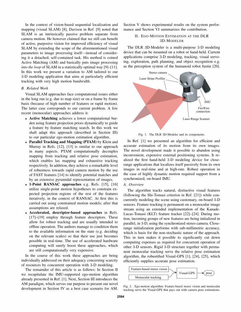
The DLR 3D-Modeler is a multi-purpose 3-D modelingdevice that can be mounted on a robot or hand-held. Currentapplications comprise 3-D modeling, tracking, visual servo-ing, exploration, path planning, and object recognition e.g.as the perception system of the humanoid robot Justin [20].
Laser Stripe Profiler
Stereo camera
FireWireconnection
IMU
Laser-Range Scanner
Fig. 1. The DLR 3D-Modeler and its components.
In Ref. [1] we presented an algorithm for efficient andaccurate estimation of its motion from its own images.The novel development made it possible to abandon usinginconvenient, expensive external positioning systems. It re-alized the first hand-held 3-D modeling device for close-range applications that localizes itself passively from its ownimages in real-time and at high-rate. Robust operation inthe case of highly dynamic motion required support from asynchronized, on-board IMU.A. Overview
The algorithm tracks natural, distinctive visual features(following the Shi-Tomasi criterion in Ref. [21]) while con-currently modeling the scene using customary, on-board 3-Dsensors. Feature tracking is permanent on a monocular imagestream using an extended implementation of the Kanade-Lucas-Tomasi (KLT) feature tracker [22]–[24]. During mo-tion, incoming groups of new features are being initialized inparallel, in 3-D, using the synchronized stereo camera. Close-range initialization performs with sub-millimetric accuracy,which is basis for the non-stochastic nature of the approach.This in turn makes it possible to significantly cut downcomputing expenses as required for concurrent operation ofother 3-D sensors. Rigid 3-D structure together with perma-nent monocular tracking serve the relative pose estimationalgorithm, the robustified Visual-GPS [1], [24], [25], whichefficiently supplies accurate pose estimation.
Visual-GPSFeature-based stereo vision
Monocular trackingpose
Fig. 2. Ego-motion algorithm: Feature-based stereo vision and monoculartracking serve the Visual-GPS that pays out with camera pose estimations.
2594
Note our accordance with the PTAM paradigm of reducingdegrees of freedom (DoF) in high-rate estimation in order toachieve better performance [12]. PTAM reduced them from6+3×N in general SLAM (N is the number of features)to 6 in PTAM, which estimates the further DoF (mapping)and absolute camera poses in a concurrent thread, at lowerrate, from selected keyframes. Mapping in our algorithmalso relies on keyframes, but substitutes bundle adjustmentby accurate, feature-based stereo vision. The latter is com-putationally cheaper and it furthermore contributes absolutescaling—a prerequisite in 3-D modeling.
B. Sequential Feature TrackingSequential feature tracking is a predictive feature search
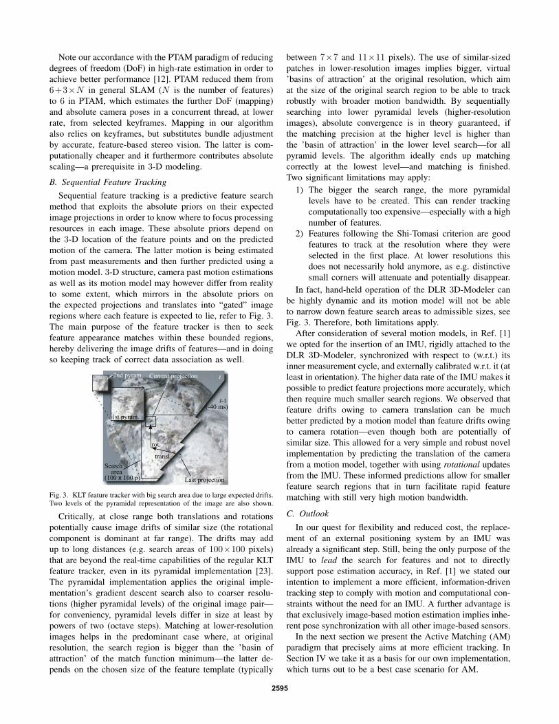
method that exploits the absolute priors on their expectedimage projections in order to know where to focus processingresources in each image. These absolute priors depend onthe 3-D location of the feature points and on the predictedmotion of the camera. The latter motion is being estimatedfrom past measurements and then further predicted using amotion model. 3-D structure, camera past motion estimationsas well as its motion model may however differ from realityto some extent, which mirrors in the absolute priors onthe expected projections and translates into “gated” imageregions where each feature is expected to lie, refer to Fig. 3.The main purpose of the feature tracker is then to seekfeature appearance matches within these bounded regions,hereby delivering the image drifts of features—and in doingso keeping track of correct data association as well.
t-1
t
1st pyram.
Last projection
Current projection
Searcharea
transl.
rot.
(100 x 100 p)
2nd pyram.
(-40 ms)
Fig. 3. KLT feature tracker with big search area due to large expected drifts.Two levels of the pyramidal representation of the image are also shown.
Critically, at close range both translations and rotationspotentially cause image drifts of similar size (the rotationalcomponent is dominant at far range). The drifts may addup to long distances (e.g. search areas of 100×100 pixels)that are beyond the real-time capabilities of the regular KLTfeature tracker, even in its pyramidal implementation [23].The pyramidal implementation applies the original imple-mentation’s gradient descent search also to coarser resolu-tions (higher pyramidal levels) of the original image pair—for conveniency, pyramidal levels differ in size at least bypowers of two (octave steps). Matching at lower-resolutionimages helps in the predominant case where, at originalresolution, the search region is bigger than the ’basin ofattraction’ of the match function minimum—the latter de-pends on the chosen size of the feature template (typically
between 7×7 and 11×11 pixels). The use of similar-sizedpatches in lower-resolution images implies bigger, virtual’basins of attraction’ at the original resolution, which aimat the size of the original search region to be able to trackrobustly with broader motion bandwidth. By sequentiallysearching into lower pyramidal levels (higher-resolutionimages), absolute convergence is in theory guaranteed, ifthe matching precision at the higher level is higher thanthe ’basin of attraction’ in the lower level search—for allpyramid levels. The algorithm ideally ends up matchingcorrectly at the lowest level—and matching is finished.Two significant limitations may apply:
1) The bigger the search range, the more pyramidallevels have to be created. This can render trackingcomputationally too expensive—especially with a highnumber of features.
2) Features following the Shi-Tomasi criterion are goodfeatures to track at the resolution where they wereselected in the first place. At lower resolutions thisdoes not necessarily hold anymore, as e.g. distinctivesmall corners will attenuate and potentially disappear.
In fact, hand-held operation of the DLR 3D-Modeler canbe highly dynamic and its motion model will not be ableto narrow down feature search areas to admissible sizes, seeFig. 3. Therefore, both limitations apply.
After consideration of several motion models, in Ref. [1]we opted for the insertion of an IMU, rigidly attached to theDLR 3D-Modeler, synchronized with respect to (w.r.t.) itsinner measurement cycle, and externally calibrated w.r.t. it (atleast in orientation). The higher data rate of the IMU makes itpossible to predict feature projections more accurately, whichthen require much smaller search regions. We observed thatfeature drifts owing to camera translation can be muchbetter predicted by a motion model than feature drifts owingto camera rotation—even though both are potentially ofsimilar size. This allowed for a very simple and robust novelimplementation by predicting the translation of the camerafrom a motion model, together with using rotational updatesfrom the IMU. These informed predictions allow for smallerfeature search regions that in turn facilitate rapid featurematching with still very high motion bandwidth.
C. Outlook
In our quest for flexibility and reduced cost, the replace-ment of an external positioning system by an IMU wasalready a significant step. Still, being the only purpose of theIMU to lead the search for features and not to directlysupport pose estimation accuracy, in Ref. [1] we stated ourintention to implement a more efficient, information-driventracking step to comply with motion and computational con-straints without the need for an IMU. A further advantage isthat exclusively image-based motion estimation implies inhe-rent pose synchronization with all other image-based sensors.
In the next section we present the Active Matching (AM)paradigm that precisely aims at more efficient tracking. InSection IV we take it as a basis for our own implementation,which turns out to be a best case scenario for AM.
2595
III. THE ACTIVE MATCHING PARADIGM
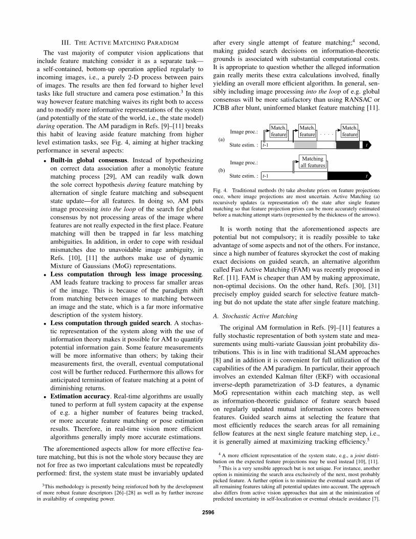
The vast majority of computer vision applications thatinclude feature matching consider it as a separate task—a self-contained, bottom-up operation applied regularly toincoming images, i.e., a purely 2-D process between pairsof images. The results are then fed forward to higher leveltasks like full structure and camera pose estimation.3 In thisway however feature matching waives its right both to accessand to modify more informative representations of the system(and potentially of the state of the world, i.e., the state model)during operation. The AM paradigm in Refs. [9]–[11] breaksthis habit of leaving aside feature matching from higherlevel estimation tasks, see Fig. 4, aiming at higher trackingperformance in several aspects:• Built-in global consensus. Instead of hypothesizing
on correct data association after a monolytic featurematching process [29], AM can readily walk downthe sole correct hypothesis during feature matching byalternation of single feature matching and subsequentstate update—for all features. In doing so, AM putsimage processing into the loop of the search for globalconsensus by not processing areas of the image wherefeatures are not really expected in the first place. Featurematching will then be trapped in far less matchingambiguities. In addition, in order to cope with residualmismatches due to unavoidable image ambiguity, inRefs. [10], [11] the authors make use of dynamicMixture of Gaussians (MoG) representations.
• Less computation through less image processing.AM leads feature tracking to process far smaller areasof the image. This is because of the paradigm shiftfrom matching between images to matching betweenan image and the state, which is a far more informativedescription of the system history.
• Less computation through guided search. A stochas-tic representation of the system along with the use ofinformation theory makes it possible for AM to quantifypotential information gain. Some feature measurementswill be more informative than others; by taking theirmeasurements first, the overall, eventual computationalcost will be further reduced. Furthermore this allows foranticipated termination of feature matching at a point ofdiminishing returns.
• Estimation accuracy. Real-time algorithms are usuallytuned to perform at full system capacity at the expenseof e.g. a higher number of features being tracked,or more accurate feature matching or pose estimationresults. Therefore, in real-time vision more efficientalgorithms generally imply more accurate estimations.
The aforementioned aspects allow for more effective fea-ture matching, but this is not the whole story because they arenot for free as two important calculations must be repeatedlyperformed: first, the system state must be invariably updated
3This methodology is presently being reinforced both by the developmentof more robust feature descriptors [26]–[28] as well as by further increasein availability of computing power.
after every single attempt of feature matching;4 second,making guided search decisions on information-theoreticgrounds is associated with substantial computational costs.It is appropriate to question whether the alleged informationgain really merits these extra calculations involved, finallyyielding an overall more efficient algorithm. In general, sen-sibly including image processing into the loop of e.g. globalconsensus will be more satisfactory than using RANSAC orJCBB after blunt, uninformed blanket feature matching [11].
Image proc.:
State estim. : t-1
Match.feature
Match.feature
t
Match.feature
Image proc.:
State estim. : t-1
Matchingall features
t
(a)
(b)
Fig. 4. Traditional methods (b) take absolute priors on feature projectionsonce, where image projections are most uncertain. Active Matching (a)recursively updates (a representation of) the state after single featurematching so that feature projection priors can be more accurately estimatedbefore a matching attempt starts (represented by the thickness of the arrows).
It is worth noting that the aforementioned aspects arepotential but not compulsory; it is readily possible to takeadvantage of some aspects and not of the others. For instance,since a high number of features skyrocket the cost of makingexact decisions on guided search, an alternative algorithmcalled Fast Active Matching (FAM) was recently proposed inRef. [11]. FAM is cheaper than AM by making approximate,non-optimal decisions. On the other hand, Refs. [30], [31]precisely employ guided search for selective feature match-ing but do not update the state after single feature matching.
A. Stochastic Active Matching
The original AM formulation in Refs. [9]–[11] features afully stochastic representation of both system state and mea-surements using multi-variate Gaussian joint probability dis-tributions. This is in line with traditional SLAM approaches[8] and in addition it is convenient for full utilization of thecapabilities of the AM paradigm. In particular, their approachinvolves an extended Kalman filter (EKF) with occasionalinverse-depth parametrization of 3-D features, a dynamicMoG representation within each matching step, as wellas information-theoretic guidance of feature search basedon regularly updated mutual information scores betweenfeatures. Guided search aims at selecting the feature thatmost efficiently reduces the search areas for all remainingfellow features at the next single feature matching step, i.e.,it is generally aimed at maximizing tracking efficiency.5
4 A more efficient representation of the system state, e.g., a joint distri-bution on the expected feature projections may be used instead [10], [11].
5 This is a very sensible approach but is not unique. For instance, anotheroption is minimizing the search area exclusively of the next, most probablypicked feature. A further option is to minimize the eventual search areas ofall remaining features taking all potential updates into account. The approachalso differs from active vision approaches that aim at the minimization ofpredicted uncertainty in self-localization or eventual obstacle avoidance [7].
2596
IV. ACTIVE MATCHING WITH KNOWN STRUCTURE:A BEST CASE SCENARIO
When using AM to guide a feature by feature matchingsearch, we are essentially modifying visual parameters forbetter perception of an active vision system—cf. Section I-A.Here the parameters include purposive decisions on whichfeature to seek for, as well as further parameters requiredfor the search (e.g. search regions). This is a closed-loopproblem where the current decision is conditioned to the taskat hand (minimizing future search regions), which in turndepends on the results of past decisions.
AM recursively generates updated search regions subjectto the accumulated information on the system’s state (i.e.,robot motion, 3-D scene, and perhaps the tracking quality ofindividual features). For efficiency reasons, the original AMformulation in Refs. [9]–[11] makes use of the 2-D projectionof the current 3-D state estimate instead: the joint distributionon feature projections. It includes absolute priors on featureprojection locations as well as relative priors on the corre-lations between these locations.6 After every measurementthey use the correlations to update absolute priors on furtherfeature projections, i.e., future search regions, see Fig. 4.
On a feature by feature decision-taking basis, the com-manded feature matching process is expected to maximizeinformation gain so that the updated information on thesystem’s state will minimize future search areas. In SLAM,inferring on the system’s state in the light of a single featuredrift is however hard, because both, 3-D scene and cameramotion, are uncertain and indistinguishable to some extent.Less information can be gathered and eventual projectionpredictions will remain uncertain. Quite the contrary in ourcase of accurate 3-D scene knowledge (Section II-A) whereimmediate inference of camera motion from a few featuredrifts is possible. Furthermore, all remaining feature driftswill only depend precisely on that newly estimated motion.For this reason we assert that non-stochastic AM with knownstructure is a best case scenario for AM where eventualsearch regions can be reduced outright. This is basically thesame message as in Ref. [10]; the authors observe especiallygood performance of AM where “priors on absolute featurelocations will be weak but priors on relative locations maystill be strong.”
Other authors have performed motion prediction fromsingle feature tracking in the context of SLAM. In Ref. [16]Civera et al. update expected projections of features from asingle bearing result using the state transition equations ofan EKF; this is however under-determined and, as explainedabove, is in the presence of uncertain structure, which yieldslarge search regions. The authors circumvent the problemby not performing all calculations but data association inthe context of random, iterative sampling instead. On theopposite side, Scaramuzza et al. in Ref. [15] fully estimatemotion from a sole correspondence but they employ a very
6 In doing so, [9]–[11] are the first to use the full stochastic representationof feature projections during feature search. It includes the correlations thatreflect the stiffness of the structure estimation as well as the common motion.This is a similar problem to neglecting covariances in regular SLAM [32].
restrictive motion model. Further, in Ref. [13] Klein andMurray introduce an efficient, inter-frame rotation estimatorto aid tracking, using whole low-resolution images. It is onthe assumption that the camera either senses at far range oronly rotates—otherwise it fails in close-range translations.
Our approach is as follows: We aim at rapid, full (6-D)camera motion preliminary estimation using a minimal set offeatures thanks to our 3-D knowledge of scene features. Thisestimation will be used to update priors on feature locationsyet to be measured. Now very small residuals will allow forextensive feature tracking and final accurate pose estimation(e.g. via Visual-GPS) in a highly efficient way—cf. Fig. 2.
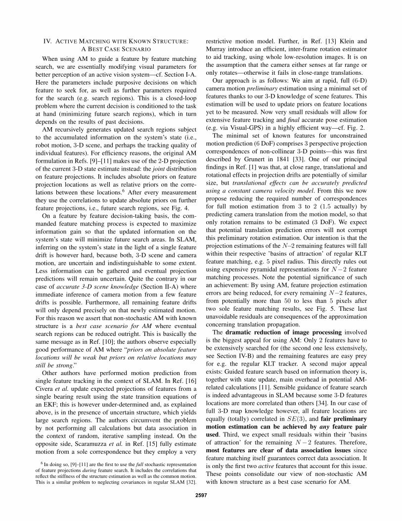
The minimal set of known features for unconstrainedmotion prediction (6 DoF) comprises 3 perspective projectioncorrespondences of non-collinear 3-D points—this was firstdescribed by Grunert in 1841 [33]. One of our principalfindings in Ref. [1] was that, at close range, translational androtational effects in projection drifts are potentially of similarsize, but translational effects can be accurately predictedusing a constant camera velocity model. From this we nowpropose reducing the required number of correspondencesfor full motion estimation from 3 to 2 (1.5 actually) bypredicting camera translation from the motion model, so thatonly rotation remains to be estimated (3 DoF). We expectthat potential translation prediction errors will not corruptthis preliminary rotation estimation. Our intention is that theprojection estimations of the N−2 remaining features will fallwithin their respective ’basins of attraction’ of regular KLTfeature matching, e.g. 5 pixel radius. This directly rules outusing expensive pyramidal representations for N−2 featurematching processes. Note the potential significance of suchan achievement: By using AM, feature projection estimationerrors are being reduced, for every remaining N−2 features,from potentially more than 50 to less than 5 pixels aftertwo sole feature matching results, see Fig. 5. These lastunavoidable residuals are consequences of the approximationconcerning translation propagation.
The dramatic reduction of image processing involvedis the biggest appeal for using AM: Only 2 features have tobe extensively searched for (the second one less extensively,see Section IV-B) and the remaining features are easy preyfor e.g. the regular KLT tracker. A second major appealexists: Guided feature search based on information theory is,together with state update, main overhead in potential AM-related calculations [11]. Sensible guidance of feature searchis indeed advantageous in SLAM because some 3-D featureslocations are more correlated than others [34]. In our case offull 3-D map knowledge however, all feature locations areequally (totally) correlated in SE(3), and fair preliminarymotion estimation can be achieved by any feature pairused. Third, we expect small residuals within their ’basinsof attraction’ for the remaining N −2 features. Therefore,most features are clear of data association issues sincefeature matching itself guarantees correct data association. Itis only the first two active features that account for this issue.These points consolidate our view of non-stochastic AMwith known structure as a best case scenario for AM.
2597
A. The KLT Feature Tracker with Larger Search Regions
The KLT feature tracker is able to cope with larger featuresearch regions by using pyramidal representations of imagepatches, refer to [23], [24] and Section II-B. This howeverposes difficulties both in computational cost and in successfulfeature matching at higher pyramidal levels.
Apart from improvements in image-processing operatorsand the use of AM itself, we performed two significant mod-ifications to the tracker to further combat these limitations:
1) The height of the pyramidal representation of images islimited, for two reasons: first, the generation of imagesof different resolution in the context of the KLT featuretracker is expensive due to associated filtering and gra-dient computations; second, feature tracking at lowerresolutions is prone to errors because features wereselected at the original resolution in the first place.We opt for subsampling the original patch only once.
2) At the subsampled level we perform exhaustive tem-plate search instead of gradient descent search. Other-wise matching would get stuck in local minima be-cause the search region at that resolution is still biggerthan the template size. We use similar-sized templatesto the ones at original resolution, which correspond toareas four times bigger at original resolution. Sequen-tial, exhaustive template search using bigger templatesat lower resolutions is very robust to ambiguities.
We employ this KLT implementation for extensive track-ing of a minimal set of two active features, cf. Section IV-B.
Along with big search areas and data association issues,motion blur is a third drawback of rapid camera motion.It precludes accurate, point-wise feature tracking. In Refs.[12], [13] Klein and Murray meet with this problem. Theyameliorate the damage using pyramidal representations ofimages, edge features, and even by exploiting its effects onimages (directional image flow). In such cases tracking iscoarsely warranted but accurate pose estimation is not. Inthis work we put stress on avoiding motion blur in the firstplace because highly-dynamic 3-D modeling requires accu-rate pose estimation all the time. Motion blur is minimized byusing shorter shutter times (in our case a few milliseconds);adequate imaging can be facilitated by using wide aperture,valuable cameras, as well as proper scene illumination.
B. Preliminary Pose Estimation from Two Feature Matches
In this section we present an algorithm for rotationestimation from two sequentially tracked features. Thisinitial estimation CRptr, together with translational prop-agation following a constant velocity motion model, willprovide highly tight priors on all other feature projections.These will eventually allow for rapid, robust feature trackingand accurate camera pose estimation in the exact samemanner as in Ref. [1].
The algorithm is detailed in Alg. 1 and Fig. 5. The choiceof the active features p and q is quite immaterial—providedthey were sequentially tracked during the last frames It−1
and It, and their templates at lower resolution are distinctive.
We choose the two most distant valid features in the imagein order to avoid noise in the estimation of roll rotation CRr.The pan+tilt rotation CRpt is estimated ( ) from the firstactive feature p. Together with CRr they form CRptr.
Algorithm 1 Pose est. and correction from a minimal set.Require: Last tracked features and last camera transl. Ctt−1.
repeatPick first active feature p
Apply transl. propagation: pttra =proj
(C pt−1−Ctt−1
)Exhaustive template match around pt
tra {wide search}until reliable match pt {normally 1×}Estimate minimal rotation (2 DoF): CR
t−1, t
pt {Eq. (1)}..............................................................................................repeat
Pick second active feature q
Apply transl. propagation: C qttra =C qt−1−Ctt−1
Apply minimal rotation: qttra+pt =proj
(CR
t−1, t
pt · C qttra)
Exhaust. templ. match around qttra+pt {narrow search}
until reliable match qt {normally 1×}Estimate remaining rotation (1 DoF): CR
t−1, t
r {Eq. (2)}..............................................................................................Pick random validation set e.g. 1..5v
Apply translation propagation: 1..5C vt
tra =1..5C vt−1−Ctt−1
Apply rotation: 1..5vttra+ptr =proj
(CR
t−1, t
pt ·CRt−1, t
r · 1..5C vt
tra)
Valid. by regular KLT tracker on 1..5vttra+ptr {else restart}
..............................................................................................Apply transl. propagation to i
C ft
tra=i
C ft−1−Ctt−1, ∀ if ∈It
Apply rotation: ift
tra+ptr =proj(CR
t−1, t
pt ·CRt−1, t
r · iC f
t
tra)
return updated feat. projections ift
tra+ptr for regular KLT.
From the discrepancy between the propagated estimationpt
tra and the exhaustive first matching result pt, the minimalcamera rotation potentially responsible for it (2 DoF) reads:
CRt−1, t
pt
{axis: C pt
tra× C pt
angle: ± arccos(
C pttra · C pt
) (1)
where Cpt = Cpt/|Cpt| and Cpt is the 3-D location of a
feature p in the camera reference frame SC at time t. C pt
is the direction in SC of the 2-D, actually tracked feature pt.
From the second match qt the only remaining DoF canbe estimated: roll rotation CR
t−1, t
r around the axis C pt thatrelates the planes containing the estimated projection C qt
tra+ptand the actual one C qt:
CRt−1, t
r
{axis: C pt
angle:± arccos((
C pt×C qttra+pt
)·(C pt×C qt
)) (2)
that jointly with the pan+tilt rotation in Eq. (1) yields
CRt−1, t
ptr = CRt−1, t
pt · CRt−1, t
r ,
which is good estimate of the camera rotation between t−1and t. Together with the last camera translation Ctt−1 itcan be used to recompute prior beliefs on further featureprojections. Note that the pan+tilt rotation CRpt obtainedfrom feature p was also used to better track feature q.
2598
Image proc.:
State estim. : t-1 +trans. prop.
#1
+pan+tilt
#2
+roll
val. KLT
t (V-GPS)
p
q
vActive feat. #1
Active feat. #2
Validation feature (and rest of features)
p
p q
q
qSearch regions
t
t
t
t
t
t
t
t
t
t-1
t-1
t-1tra
tra
tra+pt
tratra+pt
tra+ptr
vv
vv
R t-1,tptC
R t-1,trC
Fig. 5. Top: Pictorial schematic on the 2-D estimations involved. Two activefeatures p and q as well as the resulting estimation steps on a further featurev are detailed. The latter is tracked using the regular KLT feature tracker.Bottom: Time evolution of state estimation w.r.t. the image processing steps.
After successful tracking of features p and q we opt fortracking a random subset of five of the remaining featuresin order to validate the rotation hypothesis in case of mis-matches or inaccurate translational motion propagation. Thevalidation features are rapidly tracked using the standard,gradient descent KLT tracker at the original resolution only.Here correct matching demands projection accuracies of halfof the template size (e.g. 11×11, thus 5 pixels). Valid hy-potheses bring about rapid, extensive matching of all remain-ing features if (typically 20 to 50), as in the validation step.
Two types of errors may appear when searching for activefeatures: First, indistinctive matching templates at lowerresolution, or corrupted projections (e.g. occlusions). Thefrequency of these errors is minimized thanks to sequentialmatching. They are best detected during matching itself—aresignalized and will not be further used as active features.Second, image ambiguity may cause incorrect data associ-ation (false positives) even though exhaustive search andsequential matching minimize the risk. Consistency checksw.r.t. the state history support correct data association [29],[31]—this is our validation step. Both types of errors arehowever rare in regular operation. Since hypothesis genera-tion (tracking of p and q) is expensive, we opt for rigorouspreemption: one sole hypothesis will be generated unless theaforementioned errors appear. In exceptional cases of mul-tiple errors at the same image, the computational overheadmay exceed the time budget for matching (e.g. 20 ms). Theseoccasional peaks can be filtered out by making use of animage buffer, e.g., of the last two images. This implies a la-tency of e.g. 80 ms, which is admissible in most applications.Furthermore, occasional tracking losses are still possiblee.g. in untextured scenes or unfinished stereo initialization.We implemented a SURF-based relocalization stage to reg-ister back to former KLT features [27]. In this case absolutepose estimation is not provided, for several seconds.
The sizes of the search areas for the two active featuresare empirically based on worst case experiments at 25 Hz.They amount to circles of 50 and 25 pixels radii respectively.The second search area is smaller because CRpt is known.7
7 A strap considering both, roll orientation uncertainty and translationalpropagation error, could allow tighter search for the second active feature.
Typical matching times on a notebook equipped with anIntel R© Core
TM2 Duo P8700 processor are: for active feature
#1 3.2 ms (50 p. radius) or 2.3 ms (40 p.); for active feature#2 1.3 ms (25 p. radius) or 1.0 ms (20 p.); standard matchingof 5 validation features takes 0.6 ms; the remaining featuresrequire 1.7 ms (15 features) or 2.7 ms (20). Relative pose es-timation using V-GPS takes between 1.5 and 2.3 ms. Thus allcalculations typically take 10 ms on one thread—acquisitionrate is 25 Hz. A second thread is occasionally prompted forstereo initialization. Therefore, a vast amount of resources isleft for I/O, visualization, and most importantly for operationof the other 3-D sensors.
It is worth noting that the approach scales well with increa-sing frame rate since it facilitates tracking through smalleractive search areas—at constant target motion bandwidth.
V. EXPERIMENTAL VALIDATION
The current contribution addresses feature matching ac-celeration and its robustness to rapid camera motion. Olderpublications in Refs. [1], [24] already provided experimentalvalidation of the vision-based ego-motion estimation algo-rithm and detailed its high estimation accuracy. These aspectsremain unchanged here.
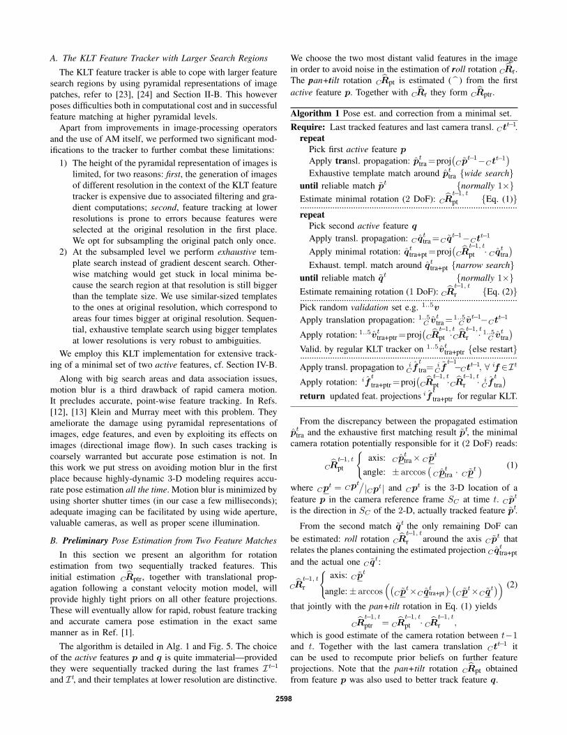
The robustness of the approach is demonstrated usingthe same challenging sequence as in Ref. [1], now withoutusing synchronized inertial data. Fig. 6 displays a typicalframe that shows both active features, the validation set,as well as remaining features. The authors suggest that thereader retrieves the processed video stream from the Inter-net at www.robotic.dlr.de/Klaus.Strobl/icra2011.Robust feature tracking holds during the entire sequence.
Active feature #1Active feature #2
Validationfeatures
expectedfound
(radius 40 p.)(rad. 20 p.)
Fig. 6. Detail of a frame including two active features, three validationfeatures, and a number of current and past regular features.
The accompanying video demonstrates real-time operationof the approach, concurrently with scanning and meshing ofa scene. All calculations (includ. visualization) are performedon a single, Intel R© Core
TM2 Duo P8700 processor notebook.
VI. CONCLUSIONS
Recently in Ref. [1] we presented the self-referencedDLR 3D-Modeler. It was the first hand-held 3-D mode-ling device for close-range applications that localizes itselfpassively from its own images in real-time, at high-rate.Since pose estimation here relies on accurate feature track-ing, challenged feature tracking by rapid camera motionnaturally compromises accurate pose estimation in real-time.
2599
In Ref. [1] we introduced a novel approach to facilitatefeature tracking in the particularly challenging case of rapidcamera motion at close range, together with concurrent 3-Dmodeling. It includes information from an inertial measu-rement unit (IMU), synchronized and rigidly attached to theDLR 3D-Modeler.
In this work we achieve robust and efficient feature track-ing in rapid, close-range motion without the use of inertialdata. This is an important contribution, both in order to avoidcalibration and synchronization issues of the IMU, as well asto further reduce hardware requirements for 3-D modeling.We believe it is precisely through flexible, passive, lighter,smaller, and more affordable sensors that machine perceptionwill eventually enable the breakthrough of service robotics.
The current novel approach for tracking casts the regularKLT feature tracker into the Active Matching paradigm byfully using and updating full state estimations during thefeature tracking process itself. In particular, a minimal set offeatures provides preliminary motion estimation that in turnenables fastest operation of the KLT feature tracker on allremaining fellow features. Separate treatment of feature driftsowing to camera translation and rotation makes it possibleto use a minimal set of only two features.
Future work will focus on more efficient stereo initial-ization and image processing in general. In addition, a mo-nocular implementation is being considered for constrainedscenes, or scenarios where absolute scaling is not required.
REFERENCES[1] K. H. Strobl, E. Mair, T. Bodenmuller, S. Kielhofer, W. Sepp,
M. Suppa, D. Burschka, and G. Hirzinger, “The Self-ReferencedDLR 3D-Modeler,” in Proceedings of the IEEE/RSJ InternationalConference on Intelligent Robots and Systems (IROS), St. Louis, MO,USA, October 2009, pp. 21–28, best paper finalist.
[2] Y. Aloimonos, “Active Vision Revisited,” in Active Perception, Y. Aloi-monos, Ed. Lawrence Erlbaum Associates, 1993, pp. 1–18.
[3] D. Marr, Vision: A Computational Investigation into the HumanRepresentation and Processing of Visual Information. San Francisco,CA, USA: W.H.Freeman & Co Ltd., 1983.
[4] D. H. Ballard, “Animate Vision,” Artificial Intelligence Journal, no. 48,pp. 57–86, 1991.
[5] J. Schiehlen and E. D. Dickmanns, “Design and Control of a Ca-mera Platform for Machine Vision,” in Proceedings of the IEEE/RSJInternational Conference on Intelligent Robots and Systems (IROS),Neubiberg, Germany, September 1994, pp. 2058–2063.
[6] A. J. Davison, “Mobile Robot Navigation Using Active Vision,” PhDThesis, Robotics Research Group, Department of Engineering Science,University of Oxford, Oxford, UK, October 1999.
[7] J. F. Seara, K. H. Strobl, E. Martin, and G. Schmidt, “Task-orientedand Situation-Dependent Gaze Control for Vision Guided AutonomousWalking,” in Proc. of the IEEE/RAS Int. Conf. on Humanoid Robots(Humanoids), Munich and Karlsruhe, Germany, Oct. 2003, pp. 1–23.
[8] A. J. Davison, I. Reid, N. Molton, and O. Stasse, “MonoSLAM: Real-Time Single Camera SLAM,” IEEE Transactions on Pattern Analysisand Machine Intelligence, vol. 29, no. 6, pp. 1052–1067, June 2007.
[9] A. J. Davison, “Active Search for Real-Time Vision,” in Proceedingsof the International Conference on Computer Vision (ICCV), Nice,France, October 2005, pp. 66–73.
[10] M. Chli and A. J. Davison, “Active Matching,” in Proceedings of theEuropean Conference on Computer Vision (ECCV), Marseille, France,October 2008, pp. 72–85.
[11] ——, “Active Matching for Visual Tracking,” Robotics and Au-tonomous Systems, vol. 57, no. 12, pp. 1173–1187, 2009.
[12] G. Klein and D. Murray, “Parallel Tracking and Mapping for SmallAR Workspaces,” in Proc. of the Sixth IEEE and ACM Int. Symposiumon Mixed and Augmented Reality (ISMAR), Nara, Japan, Nov. 2007.
[13] ——, “Improving the Agility of Keyframe-Based SLAM,” in Pro-ceedings of the European Conference on Computer Vision (ECCV),Marseille, France, October 2008, pp. 802–815.
[14] E. Rosten and T. Drummond, “Machine Learning for High-SpeedCorner Detection,” in Proceedings of the European Conference onComputer Vision (ECCV), vol. 1, May 2006, pp. 430–443.
[15] D. Scaramuzza, F. Fraundorfer, and R. Siegwart, “Real-Time Mono-cular Visual Odometry for On-Road Vehicles with 1-Point RANSAC,”in Proceedings of the IEEE International Conference on Robotics andAutomation (ICRA), Kobe, Japan, May 2009, pp. 4293–4299.
[16] J. Civera, O. G. Grasa, A. J. Davison, and J. M. M. Montiel, “1-PointRANSAC for EKF-Based Structure from Motion,” in Proceedingsof the IEEE/RSJ International Conference on Intelligent Robots andSystems (IROS), St. Louis, MO, USA, October 2009, pp. 3498–3504.
[17] D. Chekhlov, M. Pupilli, W. Mayol-Cuevas, and A. Calway,“Real-Time and Robust Monocular SLAM Using Predictive Multi-Resolution Descriptors,” in Proceedings of the 2nd InternationalSymposium on Visual Computing (ISVC), Nov. 2006, pp. 276–285.
[18] ——, “Robust Real-Time Visual SLAM Using Scale Prediction andExemplar Based Feature Description,” in Proceedings of the IEEEConference on Computer Vision and Pattern Recognition (CVPR),Minneapolis, MN, USA, June 2007, pp. 1–7.
[19] E. Eade and T. Drummond, “Unified Loop Closing and Recovery forReal Time Monocular SLAM,” in Proceedings of the British MachineVision Conference (BMVC), September 2008.
[20] C. Borst et al., “Rollin’ Justin - Mobile Platform with Variable Base,”in Proceedings of the IEEE International Conference on Robotics andAutomation (ICRA), Kobe, Japan, May 2009, best video award.
[21] J. Shi and C. Tomasi, “Good Features to Track,” in Proceedings of theInternational Conference on Pattern Recognition (ICPR), Jerusalem,Israel, October 1994, pp. 593–600.
[22] S. Birchfield. KLT: Kanade-Lucas-Tomasi Feature Tracker. Dept. ofElectrical and Computer Engineering, Clemson University. Clemson,SC, USA. [Online]. Available: http://www.ces.clemson.edu/∼stb/klt/
[23] J.-Y. Bouguet, “Pyramidal Implementation of the Lucas Kanade Fea-ture Tracker. Description of the Algorithm,” Microprocessor ResearchLabs, Intel Corporation, Santa Clara, CA, USA, Tech. Rep., 2000.
[24] E. Mair, K. H. Strobl, M. Suppa, and D. Burschka, “Efficient Camera-Based Pose Estimation for Real-Time Applications,” in Proceedingsof the IEEE/RSJ International Conference on Intelligent Robots andSystems (IROS), St. Louis, MO, USA, October 2009, pp. 2696–2703.
[25] D. Burschka and G. D. Hager, “V-GPS – Image-Based Control for 3DGuidance Systems,” in Proc. of the IEEE/RSJ Int. Conf. on IntelligentRobots and Systems, Las Vegas, NV, USA, Oct. 2003, pp. 1789–1795.
[26] D. G. Lowe, “Distinctive Image Features from Scale-Invariant Key-points,” International Journal of Computer Vision (IJCV), vol. 60,no. 2, pp. 91–110, 2004.
[27] H. Bay, A. Ess, T. Tuytelaars, and L. Van Gool, “SURF: Speeded UpRobust Features,” Computer Vision and Image Understanding (CVIU),vol. 110, no. 3, pp. 346–359, 2008.
[28] V. Lepetit and P. Fua, “Keypoint Recognition Using RandomizedTrees,” IEEE Transactions on Pattern Analysis and Machine Intel-ligence, vol. 28, no. 9, pp. 1465–1479, 2006.
[29] J. Neira and J. D. Tardos, “Data Association in Stochastic MappingUsing the Joint Compatibility Test,” IEEE Transactions on Roboticsand Automation, vol. 17, no. 6, pp. 890–897, December 2001.
[30] J. Sola, “Multi-Camera VSLAM: from Former Information Lossesto Self-Calibration,” in Proceedings of the IEEE/RSJ InternationalConference on Intelligent Robots and Systems (IROS), San Diego, CA,USA, October 2007, in Workshop on visual SLAM.
[31] M. Kaess and F. Dellaert, “Covariance Recovery from a Square RootInformation Matrix for Data Association,” Robotics and AutonomousSystems, vol. 57, no. 12, pp. 1198–1210, 2009.
[32] J. A. Castellanos, J. D. Tardos, and G. Schmidt, “Building a GlobalMap of the Environment of a Mobile Robot: The Importance ofCorrelations,” in Proceedings of the IEEE International Conference onRobotics and Automation (ICRA), Albuquerque, New Mexico, USA,April 1997, pp. 1053–1059.
[33] J. A. Grunert, “Das Pothenotische Problem in erweiterter Gestalt; nebstBemerkungen uber seine Anwendungen in der Geodasie,” in GrunertsArchiv fur Mathematik und Physik, vol. 1, pp. 238–248, 1841.
[34] M. Chli and A. J. Davison, “Automatically and Efficiently Inferringthe Hierarchical Structure of Visual Maps,” in Proceedings of the IEEEInternational Conference on Robotics and Automation (ICRA), Kobe,Japan, May 2009, pp. 387–394.
2600
Recommended