ICC Profile Format Specification
Version 3.2November 20, 1995
International Color Consortium

© International Color Consortium ICC Profile Format Specification Version 3.2
ii November 20, 1995
Copyright Notice
Copyright (C) 1995 International Color Consortium
Permission is hereby granted, free of charge, to any person obtaining a copy of theSpecification and associated documentation files (the’ ‘Specification”) to deal inthe Specification without restriction, including without limitation the of rights touse, copy, modify, merge, publish, distribute, and/or sublicense, copies of theSpecification, and to permit persons to whom the Specification is furnished to doso, subject to the following conditions.
The above copyright notice and this permission notice shall be included in allcopies or substantial portions of the Specification.
The Specification is provided “as is”, without warranty of any kind, express,implied, or otherwise, including but not limited to the warranties ofmerchantability, fitness, for a particular purpose and noninfringement. In noevent shall the International Color Consortium be liable for any claim, damagesor other liability, whether in an action of contract, tort or otherwise, arising from,out of, or in connection with the Specification or the use or other dealings in theSpecification.
Except as contained in this notice, the name of the International ColorConsortium shall not be used in advertising or otherwise to promote the use orother dealings in this Specification without prior written authorization from theInternational Color Consortium.
Licenses and Trademarks
Rather than put a trademark symbol in every occurrence of other trademarkednames, we state that we are using the names only in an editorial fashion, and tothe benefit of the trademark owner, with no intention of infringement of thetrademark.
For additional information on the ICC:
Michael Stokes, Chairman International Color Consortium
Hewlett-Packard Company1501 Page Mill Road, MS 4U5Palo Alto, CA 94304
Phone: (415)-857-3908Fax: (415)-857-4320Internet: [email protected]

November 20, 1995 iii
© International Color Consortium ICC Profile Format Specification Version 3.2
Founding Members
Adobe Systems Inc.Agfa-Gevaert N.V.Apple Computer, Inc.Eastman Kodak CompanyFOGRA (Honorary)Microsoft CorporationSilicon Graphics, Inc.Sun Microsystems, Inc.Taligent, Inc.
Regular Members
Barco Graphics N.V.Canon Information SystemsColorAge, Inc.Corbis ProductionsDainippon Screen CorporateFuji Photo Film U.S.A., Inc.Harlequin, Inc.Hewlett Packard CompanyLight SourceLinotype-Hell AGLOGOMacbethPantone, Inc.Polaroid CorporationScitex Corporation Ltd.Sony CorporationToppan Printing Co., Ltd.Trumatch, Inc.X-Rite, IncorporatedXerox Corporation

© International Color Consortium ICC Profile Format Specification Version 3.2
iv November 20, 1995
Table of Contents
Copyright Notice . . . . . . . . . . . . . . . . . . . . . . . . . . . . . . . . . . . . . . . . . . . . . . . . . . . . . . . iiLicenses and Trademarks . . . . . . . . . . . . . . . . . . . . . . . . . . . . . . . . . . . . . . . . . . . . . . . . iiFor additional information on the ICC: . . . . . . . . . . . . . . . . . . . . . . . . . . . . . . . . . . . . iiFounding Members . . . . . . . . . . . . . . . . . . . . . . . . . . . . . . . . . . . . . . . . . . . . . . . . . . . . iiiRegular Members. . . . . . . . . . . . . . . . . . . . . . . . . . . . . . . . . . . . . . . . . . . . . . . . . . . . . . iii
0 Introduction 1
0.1. Intended Audience . . . . . . . . . . . . . . . . . . . . . . . . . . . . . . . . . . . . . . . . . . . . . . . 10.2. Organizational Description of This Specification. . . . . . . . . . . . . . . . . . . . . . 10.3. International Color Consortium . . . . . . . . . . . . . . . . . . . . . . . . . . . . . . . . . . . 20.4. Device Profiles . . . . . . . . . . . . . . . . . . . . . . . . . . . . . . . . . . . . . . . . . . . . . . . . . . . 20.5. Profile Element Structure. . . . . . . . . . . . . . . . . . . . . . . . . . . . . . . . . . . . . . . . . . 30.6. Embedded Profiles . . . . . . . . . . . . . . . . . . . . . . . . . . . . . . . . . . . . . . . . . . . . . . . 40.7. Registration Authority . . . . . . . . . . . . . . . . . . . . . . . . . . . . . . . . . . . . . . . . . . . 40.8. Redundant Data Arbitration . . . . . . . . . . . . . . . . . . . . . . . . . . . . . . . . . . . . . . 5
1 Scope 6
2 Normative references 7
3 Conformance 9
4 Definitions 10
5 Notation, symbols and abbreviations 12
5.1. General . . . . . . . . . . . . . . . . . . . . . . . . . . . . . . . . . . . . . . . . . . . . . . . . . . . . . . . . 125.2. Basic Numeric Types . . . . . . . . . . . . . . . . . . . . . . . . . . . . . . . . . . . . . . . . . . . . 12
6 Requirements 15
6.1. Header Description . . . . . . . . . . . . . . . . . . . . . . . . . . . . . . . . . . . . . . . . . . . . . 166.1.1. Profile size . . . . . . . . . . . . . . . . . . . . . . . . . . . . . . . . . . . . . . . . . . . . . . . . . 176.1.2. CMM Type . . . . . . . . . . . . . . . . . . . . . . . . . . . . . . . . . . . . . . . . . . . . . . . . 176.1.3. Profile Version . . . . . . . . . . . . . . . . . . . . . . . . . . . . . . . . . . . . . . . . . . . . . 176.1.4. Profile/Device class . . . . . . . . . . . . . . . . . . . . . . . . . . . . . . . . . . . . . . . . 186.1.5. Color Space Signatures . . . . . . . . . . . . . . . . . . . . . . . . . . . . . . . . . . . . . . 196.1.6. Profile Connection Space Signatures . . . . . . . . . . . . . . . . . . . . . . . . . . 206.1.7. Primary Platform Signature . . . . . . . . . . . . . . . . . . . . . . . . . . . . . . . . . 206.1.8. Profile Flags . . . . . . . . . . . . . . . . . . . . . . . . . . . . . . . . . . . . . . . . . . . . . . . 206.1.9. Device manufacturer and model: . . . . . . . . . . . . . . . . . . . . . . . . . . . . . 216.1.10. Attributes . . . . . . . . . . . . . . . . . . . . . . . . . . . . . . . . . . . . . . . . . . . . . . . . 21
November 20, 1995 v
© International Color Consortium ICC Profile Format Specification Version 3.2
6.1.11. Rendering Intent: . . . . . . . . . . . . . . . . . . . . . . . . . . . . . . . . . . . . . . . . . . 216.1.12. Profile Creator . . . . . . . . . . . . . . . . . . . . . . . . . . . . . . . . . . . . . . . . . . . . 22
6.2. Tag Table Definition . . . . . . . . . . . . . . . . . . . . . . . . . . . . . . . . . . . . . . . . . . . . . 226.2.1. Tag Signature . . . . . . . . . . . . . . . . . . . . . . . . . . . . . . . . . . . . . . . . . . . . . . 226.2.2. Offset. . . . . . . . . . . . . . . . . . . . . . . . . . . . . . . . . . . . . . . . . . . . . . . . . . . . . 226.2.3. Element Size. . . . . . . . . . . . . . . . . . . . . . . . . . . . . . . . . . . . . . . . . . . . . . . 236.2.4. Tag Data Requirements. . . . . . . . . . . . . . . . . . . . . . . . . . . . . . . . . . . . . . 23
6.3. Device Profile Requirements . . . . . . . . . . . . . . . . . . . . . . . . . . . . . . . . . . . . . 236.3.1. Input Profile . . . . . . . . . . . . . . . . . . . . . . . . . . . . . . . . . . . . . . . . . . . . . . . 24
6.3.1.1. Monochrome Input Profiles . . . . . . . . . . . . . . . . . . . . . . . . . . . . . 246.3.1.2. RGB Input Profiles . . . . . . . . . . . . . . . . . . . . . . . . . . . . . . . . . . . . . 256.3.1.3. CMYK Input Profiles . . . . . . . . . . . . . . . . . . . . . . . . . . . . . . . . . . . 26
6.3.2. Display Profile . . . . . . . . . . . . . . . . . . . . . . . . . . . . . . . . . . . . . . . . . . . . . 266.3.2.1. Monochrome Display Profiles. . . . . . . . . . . . . . . . . . . . . . . . . . . . 276.3.2.2. RGB Display Profiles . . . . . . . . . . . . . . . . . . . . . . . . . . . . . . . . . . . 27
6.3.3. Output Profile . . . . . . . . . . . . . . . . . . . . . . . . . . . . . . . . . . . . . . . . . . . . . 286.3.3.1. Monochrome Output Profiles . . . . . . . . . . . . . . . . . . . . . . . . . . . . 296.3.3.2. RGB and CMYK Output Profiles . . . . . . . . . . . . . . . . . . . . . . . . . 30
6.3.4. Additional Profile Formats . . . . . . . . . . . . . . . . . . . . . . . . . . . . . . . . . . . 316.3.4.1. DeviceLink Profile . . . . . . . . . . . . . . . . . . . . . . . . . . . . . . . . . . . . . 316.3.4.2. ColorSpaceConversion Profile . . . . . . . . . . . . . . . . . . . . . . . . . . . 316.3.4.3. Abstract Profile . . . . . . . . . . . . . . . . . . . . . . . . . . . . . . . . . . . . . . . . 326.3.4.4. Named Color Profile. . . . . . . . . . . . . . . . . . . . . . . . . . . . . . . . . . . . 33
6.4. Tag Descriptions . . . . . . . . . . . . . . . . . . . . . . . . . . . . . . . . . . . . . . . . . . . . . . . . 346.4.1. AToB0Tag . . . . . . . . . . . . . . . . . . . . . . . . . . . . . . . . . . . . . . . . . . . . . . . . . 356.4.2. AToB1Tag . . . . . . . . . . . . . . . . . . . . . . . . . . . . . . . . . . . . . . . . . . . . . . . . . 356.4.3. AToB2Tag . . . . . . . . . . . . . . . . . . . . . . . . . . . . . . . . . . . . . . . . . . . . . . . . . 366.4.4. blueColorantTag. . . . . . . . . . . . . . . . . . . . . . . . . . . . . . . . . . . . . . . . . . . . 366.4.5. blueTRCTag . . . . . . . . . . . . . . . . . . . . . . . . . . . . . . . . . . . . . . . . . . . . . . . 366.4.6. BToA0Tag . . . . . . . . . . . . . . . . . . . . . . . . . . . . . . . . . . . . . . . . . . . . . . . . . 366.4.7. BToA1Tag . . . . . . . . . . . . . . . . . . . . . . . . . . . . . . . . . . . . . . . . . . . . . . . . . 376.4.8. BToA2Tag . . . . . . . . . . . . . . . . . . . . . . . . . . . . . . . . . . . . . . . . . . . . . . . . . 376.4.9. calibrationDateTimeTag . . . . . . . . . . . . . . . . . . . . . . . . . . . . . . . . . . . . . 376.4.10. charTargetTag. . . . . . . . . . . . . . . . . . . . . . . . . . . . . . . . . . . . . . . . . . . . . 376.4.11. copyrightTag. . . . . . . . . . . . . . . . . . . . . . . . . . . . . . . . . . . . . . . . . . . . . . 386.4.12. deviceMfgDescTag. . . . . . . . . . . . . . . . . . . . . . . . . . . . . . . . . . . . . . . . . 386.4.13. deviceModelDescTag . . . . . . . . . . . . . . . . . . . . . . . . . . . . . . . . . . . . . . 386.4.14. gamutTag . . . . . . . . . . . . . . . . . . . . . . . . . . . . . . . . . . . . . . . . . . . . . . . . 386.4.15. grayTRCTag . . . . . . . . . . . . . . . . . . . . . . . . . . . . . . . . . . . . . . . . . . . . . . 386.4.16. greenColorantTag . . . . . . . . . . . . . . . . . . . . . . . . . . . . . . . . . . . . . . . . . 396.4.17. greenTRCTag . . . . . . . . . . . . . . . . . . . . . . . . . . . . . . . . . . . . . . . . . . . . . 396.4.18. luminanceTag . . . . . . . . . . . . . . . . . . . . . . . . . . . . . . . . . . . . . . . . . . . . . 396.4.19. measurementTag . . . . . . . . . . . . . . . . . . . . . . . . . . . . . . . . . . . . . . . . . . 406.4.20. mediaBlackPointTag . . . . . . . . . . . . . . . . . . . . . . . . . . . . . . . . . . . . . . . 406.4.21. mediaWhitePointTag. . . . . . . . . . . . . . . . . . . . . . . . . . . . . . . . . . . . . . . 406.4.22. namedColorTag . . . . . . . . . . . . . . . . . . . . . . . . . . . . . . . . . . . . . . . . . . . 40

© International Color Consortium ICC Profile Format Specification Version 3.2
vi November 20, 1995
6.4.23. namedColor2Tag . . . . . . . . . . . . . . . . . . . . . . . . . . . . . . . . . . . . . . . . . . 416.4.24. preview0Tag . . . . . . . . . . . . . . . . . . . . . . . . . . . . . . . . . . . . . . . . . . . . . . 416.4.25. preview1Tag . . . . . . . . . . . . . . . . . . . . . . . . . . . . . . . . . . . . . . . . . . . . . . 416.4.26. preview2Tag . . . . . . . . . . . . . . . . . . . . . . . . . . . . . . . . . . . . . . . . . . . . . . 416.4.27. profileDescriptionTag . . . . . . . . . . . . . . . . . . . . . . . . . . . . . . . . . . . . . . 416.4.28. profileSequenceDescTag . . . . . . . . . . . . . . . . . . . . . . . . . . . . . . . . . . . . 426.4.29. ps2CRD0Tag . . . . . . . . . . . . . . . . . . . . . . . . . . . . . . . . . . . . . . . . . . . . . . 426.4.30. ps2CRD1Tag . . . . . . . . . . . . . . . . . . . . . . . . . . . . . . . . . . . . . . . . . . . . . . 426.4.31. ps2CRD2Tag . . . . . . . . . . . . . . . . . . . . . . . . . . . . . . . . . . . . . . . . . . . . . . 426.4.32. ps2CRD3Tag . . . . . . . . . . . . . . . . . . . . . . . . . . . . . . . . . . . . . . . . . . . . . . 436.4.33. ps2CSATag . . . . . . . . . . . . . . . . . . . . . . . . . . . . . . . . . . . . . . . . . . . . . . . 436.4.34. ps2RenderingIntentTag. . . . . . . . . . . . . . . . . . . . . . . . . . . . . . . . . . . . . 436.4.35. redColorantTag . . . . . . . . . . . . . . . . . . . . . . . . . . . . . . . . . . . . . . . . . . . 446.4.36. redTRCTag . . . . . . . . . . . . . . . . . . . . . . . . . . . . . . . . . . . . . . . . . . . . . . . 446.4.37. screeningDescTag . . . . . . . . . . . . . . . . . . . . . . . . . . . . . . . . . . . . . . . . . 446.4.38. screeningTag. . . . . . . . . . . . . . . . . . . . . . . . . . . . . . . . . . . . . . . . . . . . . . 446.4.39. technologyTag . . . . . . . . . . . . . . . . . . . . . . . . . . . . . . . . . . . . . . . . . . . . 456.4.40. ucrbgTag . . . . . . . . . . . . . . . . . . . . . . . . . . . . . . . . . . . . . . . . . . . . . . . . . 466.4.41. viewingCondDescTag . . . . . . . . . . . . . . . . . . . . . . . . . . . . . . . . . . . . . . 466.4.42. viewingConditionsTag . . . . . . . . . . . . . . . . . . . . . . . . . . . . . . . . . . . . . 46
6.5. Tag Type Definitions . . . . . . . . . . . . . . . . . . . . . . . . . . . . . . . . . . . . . . . . . . . . 466.5.1. curveType . . . . . . . . . . . . . . . . . . . . . . . . . . . . . . . . . . . . . . . . . . . . . . . . . 476.5.2. dataType . . . . . . . . . . . . . . . . . . . . . . . . . . . . . . . . . . . . . . . . . . . . . . . . . . 476.5.3. dateTimeType. . . . . . . . . . . . . . . . . . . . . . . . . . . . . . . . . . . . . . . . . . . . . . 486.5.4. lut16Type. . . . . . . . . . . . . . . . . . . . . . . . . . . . . . . . . . . . . . . . . . . . . . . . . . 486.5.5. lut8Type. . . . . . . . . . . . . . . . . . . . . . . . . . . . . . . . . . . . . . . . . . . . . . . . . . . 516.5.6. measurementType . . . . . . . . . . . . . . . . . . . . . . . . . . . . . . . . . . . . . . . . . . 546.5.7. namedColorType . . . . . . . . . . . . . . . . . . . . . . . . . . . . . . . . . . . . . . . . . . . 566.5.8. namedColor2Type . . . . . . . . . . . . . . . . . . . . . . . . . . . . . . . . . . . . . . . . . . 576.5.9. profileSequenceDescType. . . . . . . . . . . . . . . . . . . . . . . . . . . . . . . . . . . . 586.5.10. s15Fixed16ArrayType . . . . . . . . . . . . . . . . . . . . . . . . . . . . . . . . . . . . . . 606.5.11. screeningType. . . . . . . . . . . . . . . . . . . . . . . . . . . . . . . . . . . . . . . . . . . . . 606.5.12. signatureType. . . . . . . . . . . . . . . . . . . . . . . . . . . . . . . . . . . . . . . . . . . . . 616.5.13. textDescriptionType . . . . . . . . . . . . . . . . . . . . . . . . . . . . . . . . . . . . . . . 616.5.14. textType. . . . . . . . . . . . . . . . . . . . . . . . . . . . . . . . . . . . . . . . . . . . . . . . . . 636.5.15. u16Fixed16ArrayType. . . . . . . . . . . . . . . . . . . . . . . . . . . . . . . . . . . . . . 636.5.16. ucrbgType . . . . . . . . . . . . . . . . . . . . . . . . . . . . . . . . . . . . . . . . . . . . . . . . 646.5.17. uInt16ArrayType . . . . . . . . . . . . . . . . . . . . . . . . . . . . . . . . . . . . . . . . . . 646.5.18. uInt32ArrayType . . . . . . . . . . . . . . . . . . . . . . . . . . . . . . . . . . . . . . . . . . 656.5.19. uInt64ArrayType . . . . . . . . . . . . . . . . . . . . . . . . . . . . . . . . . . . . . . . . . . 656.5.20. uInt8ArrayType . . . . . . . . . . . . . . . . . . . . . . . . . . . . . . . . . . . . . . . . . . . 656.5.21. viewingConditionsType . . . . . . . . . . . . . . . . . . . . . . . . . . . . . . . . . . . . 666.5.22. XYZType . . . . . . . . . . . . . . . . . . . . . . . . . . . . . . . . . . . . . . . . . . . . . . . . . 66
Annex A :Color Spaces 67

November 20, 1995 vii
© International Color Consortium ICC Profile Format Specification Version 3.2
A.1. Profile Connection Spaces . . . . . . . . . . . . . . . . . . . . . . . . . . . . . . . . . . . . . . . 67
Annex B :Embedding Profiles 71
B.1. Embedding ICC Profiles in PICT Files . . . . . . . . . . . . . . . . . . . . . . . . . . . . . 71B.2. Embedding ICC Profiles in EPS Files . . . . . . . . . . . . . . . . . . . . . . . . . . . . . . 72B.3. Embedding ICC Profiles in TIFF Files . . . . . . . . . . . . . . . . . . . . . . . . . . . . . 75
Annex C :C Header File Example 76
Annex D :PostScript Level 2 Tags 99
Annex E :Profile Connection Space Explanation 102
E.1. Introduction. . . . . . . . . . . . . . . . . . . . . . . . . . . . . . . . . . . . . . . . . . . . . . . . . . . 102E.2. Colorimetry and Its Interpretation. . . . . . . . . . . . . . . . . . . . . . . . . . . . . . . . 103E.3. Color Measurements . . . . . . . . . . . . . . . . . . . . . . . . . . . . . . . . . . . . . . . . . . . 105E.4. Colorimetry Corrections and Adjustments in Output Profiles . . . . . . . . 106E.5. Output to reflection print media . . . . . . . . . . . . . . . . . . . . . . . . . . . . . . . . . 106E.6. Output to transparency media . . . . . . . . . . . . . . . . . . . . . . . . . . . . . . . . . . . 108E.7. Negative media. . . . . . . . . . . . . . . . . . . . . . . . . . . . . . . . . . . . . . . . . . . . . . . . 109E.8. Monitor display . . . . . . . . . . . . . . . . . . . . . . . . . . . . . . . . . . . . . . . . . . . . . . . 109E.9. Colorimetry Corrections and Adjustments in Input Profiles. . . . . . . . . . 110E.10. Scanned reflection prints . . . . . . . . . . . . . . . . . . . . . . . . . . . . . . . . . . . . . . . 110E.11. Scanned transparencies . . . . . . . . . . . . . . . . . . . . . . . . . . . . . . . . . . . . . . . . 111E.12. Scanned negatives . . . . . . . . . . . . . . . . . . . . . . . . . . . . . . . . . . . . . . . . . . . . 111E.13. Computer graphics. . . . . . . . . . . . . . . . . . . . . . . . . . . . . . . . . . . . . . . . . . . . 111E.14. Scene capture. . . . . . . . . . . . . . . . . . . . . . . . . . . . . . . . . . . . . . . . . . . . . . . . . 112E.15. Colorimetric input . . . . . . . . . . . . . . . . . . . . . . . . . . . . . . . . . . . . . . . . . . . . 112E.16. Techniques for Colorimetry Corrections. . . . . . . . . . . . . . . . . . . . . . . . . . 113

© International Color Consortium ICC Profile Format Specification Version 3.2
1 November 20, 1995 Clause 0 : Introduction
0 Introduction
This specification describes the International Color Consortium Profile Format.The intent of this format is to provide a cross-platform device profile format.Such device profiles can be used to translate color data created on one deviceinto another device's native color space. The acceptance of this format byoperating system vendors allows end users to transparently move profiles andimages with embedded profiles between different operating systems. Forexample, this allows a printer manufacturer to create a single profile for multipleoperating systems.
A large number of companies and individuals from a variety of industriesparticipated in very extensive discussions on these issues. Many of thesediscussions occurred under the auspices of Forshungsgesellschaft Druck e.V.(FOGRA), the German graphic arts research institute, during 1993. The presentspecification evolved from these discussions and the ColorSync™ 1.0 profileformat.
This is a very complex set of issues and the organization of this documentstrives to provide a clear, clean, and unambiguous explanation of the entireformat. To accomplish this, the overall presentation is from a top-downperspective, beginning with a summary overview and continuing down intomore detailed specifications to a byte stream description of format.
0.1 Intended Audience
This specification is designed to provide developers and other interested partiesa clear description of the profile format. A nominal understanding of colorscience is assumed, such as familiarity with the CIELAB color space, generalknowledge of device characterizations, and familiarity of at least one operatingsystem level color management system.
0.2 Organizational Description of This Specification
This specification is organized into a number of major clauses and annexes. Eachclause and subclause is numbered for easy reference. A brief introduction isfollowed by a detailed summary of the issues involved in this documentincluding: International Color Consortium, device profiles, profile elementstructure, enbedded profiles, registration authority, and color model arbitration.
Clause 1 described the scope of this specification.
Clause 2 provides the normative references for this specification.
Clause 3 described the conformance requirements for this specification.

Clause 0 : Introduction November 20, 1995 2
© International Color Consortium ICC Profile Format Specification Version 3.2
Clause 4 provides general definitions used within this standard.
Clause 5 provides descriptions of notations, symbols and abbreviationsused in this specification.
Clause 6 describes the requirements of this specification. Sub-clause 6.1'Header Description' describes the format header definition. Sub-clause 6.2 'TagTable Definition' describes the tag table. Sub-clause 6.3 'Device ProfileRequirements' provides a top level view of what tags are required for each typeof profile classification and a brief description of the algorithmic modelsassociated with these classes. Four additional color transformation formats arealso described: device link, color space conversion, abstract transformations, andnamed color transforms. Sub-clause 6.4 'Tag Descriptions' is a detailedalgorithmic and intent description of all of the tagged elements described in theprevious clauses. Sub-clause 6.5 'Tag Type Definitions' provides a byte streamdefinition of the structures that make up the tags in sub-clause 6.4.
Annex A : 'Color Spaces' describes the color spaces used in thisspecification. Annex B : 'Embedding Profiles' provides the necessary details toembed profiles into PICT, TIFF, and EPS files. Annex C : 'C Header FileExample' provides cross-platform ANSI-C compatible header file example foreach of the device profile and color transform formats. Annex D : 'PostScriptLevel 2 Tags' provides a general description of the PostScript Level 2 tags usedin this specification. Annex E : 'Profile Connection Space Explanation' is a paperdescribing details of the profile connection space.
0.3 International Color Consortium
Considering the potential impact of this standard on various industries, aconsortium has been formed that will administer this specification and theregistration of tag signatures and descriptions. The founding members of thisconsortium include; Adobe Systems Inc., Agfa-Gevaert N.V., Apple Computer,Inc., Eastman Kodak Company, FOGRA (Honorary), Microsoft Corporation,Silicon Graphics, Inc., Sun Microsystems, Inc., and Taligent, Inc. Thesecompanies have committed to fully support this specification in their operatingsystems, platforms and applications.
0.4 Device Profiles
Device profiles provide color management systems with the informationnecessary to convert color data between native device color spaces and deviceindependent color spaces. This specification divides color devices into threebroad classifications: input devices, display devices and output devices. For eachdevice class, a series of base algorithmic models are described which performthe transformation between color spaces. These models provide a range of colorquality and performance results. Each of the base models provides different

© International Color Consortium ICC Profile Format Specification Version 3.2
3 November 20, 1995 Clause 0 : Introduction
trade-offs in memory footprint, performance and image quality. The necessaryparameter data to implement these models is described in the required portionson the appropriate device profile descriptions. This required data provides theinformation for the color management framework default color managementmodule (CMM) to transform color information between native device colorspaces. A representative architecture using these components is illustrated inFigure 1 below.
FIGURE 1.
0.5 Profile Element Structure
The profile structure is defined as a header followed by a tag table followed by aseries of tagged elements that can be accessed randomly and individually. Thiscollection of tagged elements provides three levels of information fordevelopers: required data, optional data and private data. An element tag tableprovides a table of contents for the tagging information in each individualprofile. This table includes a tag signature, the beginning address offset and sizeof the data for each individual tagged element. Signatures in this specificationare defined as a four byte hexadecimal number. This tagging scheme allowsdevelopers to read in the element tag table and then randomly access and loadinto memory only the information necessary to their particular softwareapplication. Since some instances of profiles can be quite large, this provides

Clause 0 : Introduction November 20, 1995 4
© International Color Consortium ICC Profile Format Specification Version 3.2
significant savings in performance and memory. The detailed descriptions of thetags, along with their intent, are included later in this specification.
The required tags provide the complete set of information necessary forthe default CMM to translate color information between the profile connectionspace and the native device space. Each profile class determines whichcombination of tags is required. For example, a multi-dimensional lookup tableis required for output devices, but not for display devices.
In addition to the required tags for each device profile, a number ofoptional tags are defined that can be used for enhanced color transformations.Examples of these tags include PostScript Level 2 support, calibration support,and others. In the case of required and optional tags, all of the signatures, analgorithmic description, and intent are registered with the International ColorConsortium.
Private data tags allow CMM developers to add proprietary value totheir profiles. By registering just the tag signature and tag type signature,developers are assured of maintaining their proprietary advantages whilemaintaining compatibility with the industry standard. However, the overallphilosophy of this format is to maintain an open, cross-platform standard,therefore the use of private tags should be kept to an absolute minimum.
0.6 Embedded Profiles
In addition to providing a cross-platform standard for the actual disk-basedprofile format, this specification also describes the convention for embeddingthese profiles within graphics documents and images. Embedded profiles allowusers to transparently move color data between different computers, networksand even operating systems without having to worry if the necessary profilesare present on the destination systems. The intention of embedded profiles is toallow the interpretation of the associated color data. Embedding specificationsare described in Annex B : 'Embedding Profiles' of this document.
0.7 Registration Authority
This standard requires that signatures for CMM type, device manufacturer,device model, profile tags and profile tag types be registered to insure that allprofile data is uniquely defined. The registration authority for these data is theICC Technical Secretary:
Michael HasFOGRAStreitfieldstrasse 19D-81673 Munich, GermanyTel: 49-89-4318241
© International Color Consortium ICC Profile Format Specification Version 3.2
5 November 20, 1995 Clause 0 : Introduction
Fax: 49-89-431-6896Email: [email protected]
If and when this document becomes an International Standard thisregistration responsibility must be brought into conformance with ISOprocedures. These procedures are being investigated on behalf of ICC andTC130.
0.8 Redundant Data Arbitration
There are several methods of color rendering described in the followingstructures that can function within a single CMM. If data for more than onemethod are included in the same profile, the following selection algorithmshould be used by the software implementation: if an 8 bit or 16 bit lookup tableis present, it should be used; if a lookup table is not present (and not required),the appropriate default modeling parameters are used.

Clause 1 : Scope November 20, 1995 6
© International Color Consortium ICC Profile Format Specification Version 3.2
1 Scope
This International Standard defines the data necessary to describe the colorcharacteristics used to input, display, or output images, and an associated fileformat for the exchange of this data.

© International Color Consortium ICC Profile Format Specification Version 3.2
7 November 20, 1995 Clause 2 : Normative references
2 Normative references
The following standards contain provisions which, through reference in thistext, constitute provisions of this International Standard. At the time ofpublication, the editions indicated were valid. All standards are subject torevision, and parties to agreements based on this International Standard areencouraged to investigate the possibility of applying the most recent editions ofthe standards indicated below. Members of ISO and IEC maintain registers ofcurrently valid International Standards.
CIE Publication 15.2-1986, “Colorimetry, Second Edition”
ISO 5/1:1984, “Photography (sensitometry) - Density measurements - Terms,symbols and notation”
ISO 5/2:1991, “Photography- Density measurements - Part 2: Geometricconditions for transmission density”
ISO 5/4:1983, “Photography - Density measurements - Part 4: Geometricconditions for reflection density”
ISO/IEC 646:1991, Information technology - ISO 7-bit coded character set forinformation interchange.
ISO 3664:1975, “Photography - Illumination conditions for viewing colourtransparencies and their reproductions” (Need to check against ANSIPH2.30-1989)
ISO 12641- 199X, Graphic technology - Prepress digital data exchange - Colourtargets for input scanner calibration (Equals IT8.7/1 and IT8.7/2).Approved 1995, awaiting publication by ISO.
ISO 12642 - 199X, Graphic technology - Prepress digital data exchange - Inputdata for characterization of 4-colour process printing (Equals IT8.7/3).Approved 1995, awaiting publication by ISO.
ISO 13655 - 199X, Graphic technology - Spectral measurement and colorimetriccomputation for images (Equals CGATS.5). Approved 1995, awaitingpublication by ISO.
PostScript - Language Reference Manual, Second Edition, Adobe Systems Inc.
TIFF 6.0 Specification, published by Adobe Systems Inc.,
ISO/CD 12639 Graphic Technology - Prepress digital data exchange - Tag image

Clause 2 : Normative references November 20, 1995 8
© International Color Consortium ICC Profile Format Specification Version 3.2
file format for image technology (TIFF/IT), (Incorporates ANSI IT8.8-1993and adds additional compliance options. Final approval expected late1996.)
ISO/WD 12234 Photography - Electronic still picture cameras - Removeablememory.” (TIFF/EP)
PICT Standard Specifications, published by Apple Computer, Inc.

© International Color Consortium ICC Profile Format Specification Version 3.2
9 November 20, 1995 Clause 3 : Conformance
3 Conformance
Any color management system, application, utility or device driver that is inconformance with this standard shall have the ability to read the profiles as theyare defined in this standard. Any profile-generating software and/or hardwarethat is in conformance with this standard shall have the ability to create profilesas they are defined in this standard. ICC conforming software will use the ICCprofiles in an appropriate manner.
Clause 4 : Definitions November 20, 1995 10
© International Color Consortium ICC Profile Format Specification Version 3.2
4 Definitions
For the purposes of this standard, the following definitions shall apply:
4.1 aligned
A data element is aligned with respect to a data type if the address of thedata element is an integral multiple of the number of bytes in the datatype.
4.2 ASCII string
A sequence of bytes, each containing a graphic character from ISO 646,the last character in the string being a “null” (character 0/0)
4.3 BCD
Binary Coded Decimal
4.4 big-endian
addressing the bytes within a 16, 32 or 64-bit value from the mostsignificant to the least significant, as the byte address increases
4.5 byte
An eight-bit unsigned binary integer
4.6 CMM
Color Management Module
4.7 Fixed Point Representation
Many of the tag types contain fixed point numbers. Several references canbe found (MetaFonts, etc.) illustrating the preferability of fixed pointrepresentation to pure floating point representation in very structuredcircumstances. See Table 2 for an example of fixed point representation.
4.8 offset
an address withing an ICC profile, relative to byte zero of the file
4.9 perceptual intent

© International Color Consortium ICC Profile Format Specification Version 3.2
11 November 20, 1995 Clause 4 : Definitions
A rendering intent that specifies the full gamut of the image iscompressed or expanded to fill the gamut of the destination device. Graybalance is preserved but colorimetric accuracy might not be preserved.
4.10 Rendering Intent
Rendering intent specifies the style of reproduction to be used during theevaluation of this profile in a sequence of profiles. It applies specifically tothat profile in the sequence and not to the entire sequence. Typically, theuser or application will set the rendering intent dynamically at runtime orembedding time.
4.11 saturation intent
A rendering intent that specifies the saturation of the pixels in the imageis preserved perhaps at the expense of accuracy in hue and lightness.

Clause 5 : Notation, symbols and abbreviationsNovember 20, 1995 12
© International Color Consortium ICC Profile Format Specification Version 3.2
5 Notation, symbols and abbreviations
All numeric values in this standard are expressed in decimal, unless otherwiseindicated and literal strings are denoted in this standard by enclosing them insingle quotation marks.
The following symbols and abbreviations are used in this specification.
5.1 General
5.1.1 byte offset: Number of bytes from the beginning of a field
5.1.2 h: A letter “h” is suffixed to denote a hexadecimal value.
5.1.3 SPACE : The character coded in position 2/0 of ISO/IEC 646.
5.1.4 NULL: The character coded in position 0/0 of ISO/IEC 646.
5.2 Basic Numeric Types
5.2.1 dateTimeNumber: This dateTimeNumber is a 12 byte valuerepresentation of the time and date. The actual values are encoded as 16bit unsigned integers.
5.2.2 s15Fixed16Number (s15.16): This type represents a fixed signed 4 byte/32bit quantity which has 16 fractional bits. An example of this encoding is:
Byte Offset Field name
0-1 number of the year (actual year, i.e. 1994)2-3 number of the month (1-12)4-5 number of the day of the month (1-31)6-7 number of hours (0-23)8-9 number of minutes (0-59)10-11 number of seconds (0-59)
TABLE 1.
-32768.0 80000000h0 00000000h1.0 00010000h32767 + (65535/65536) 7FFFFFFFh
TABLE 2.

© International Color Consortium ICC Profile Format Specification Version 3.2
13 November 20, 1995 Clause 5 : Notation, symbols and abbreviations
5.2.3 u16Fixed16Number : This type represents a fixed unsigned 4 byte/32 bitquantity which has 16 fractional bits. An example of this encoding is:
5.2.4 u8Fixed8Number: This type represents a fixed unsigned 2 byte/16 bitquantity which has 8 fractional bits. An example of this encoding is:
5.2.5 uInt16Number: This type represents a generic unsigned 2 byte/16 bitquantity.
5.2.6 uInt32Number: This type represents a generic unsigned 4 byte/32 bitquantity.
5.2.7 uInt64Number: This type represents a generic unsigned 8 byte/64 bitquantity.
5.2.8 uInt8Number: This type represents a generic unsigned 1 byte/8 bitquantity.
5.2.9 XYZNumber: This type represents a set of three fixed signed 4 byte/32 bitquantities used to encode CIEXYZ tristimulus values where byte usage isassigned as follows:
For relative tristimulus values, the XYZNumbers are scaled such that aperfect reflecting diffuser has a Y value of 1.0 and NOT 100.0. Tristimulusvalues must be non-negative.
0 00000000h1.0 00010000h65535 + (65535/65536) FFFFFFFFh
TABLE 3.
0 0000h1.0 0100h255 + (255/256) FFFFh
TABLE 4.
Byte Offset Content Encoding0-3 CIE X s15Fixed16Number4-7 CIE Y s15Fixed16Number8-11 CIE Z s15Fixed16Number
TABLE 5.

Clause 5 : Notation, symbols and abbreviationsNovember 20, 1995 14
© International Color Consortium ICC Profile Format Specification Version 3.2
5.2.10 Seven Bit ASCII
Hexadecimal00 nul 01 soh 02 stx 03 etx 04 eot 05 enq 06 ack 07 bel
08 bs 09 ht 0a nl 0b vt 0c np 0d cr 0e so 0f si
10 dle 11 dc1 12 dc2 13 dc3 14 dc4 15 nak 16 syn 17 etb
18 can 19 em 1a sub 1b esc 1c fs 1d gs 1e rs 1f us
20 sp 21 ! 22 “ 23 # 24 $ 25 % 26 & 27 ‘
28 ( 29 ) 2a * 2b + 2c , 2d - 2e . 2f /
30 0 31 1 32 2 33 3 34 4 35 5 36 6 37 7
38 8 39 9 3a : 3b ; 3c < 3d = 3e > 3f ?
40 @ 41 A 42 B 43 C 44 D 45 E 46 F 47 G
48 H 49 I 4a J 4b K 4c L 4d M 4e N 4f O
50 P 51 Q 52 R 53 S 54 T 55 U 56 V 57 W
58 X 59 Y 5a Z 5b [ 5c \ 5d ] 5e ^ 5f _
60 ` 61 a 62 b 63 c 64 d 65 e 66 f 67 g
68 h 69 i 6a j 6b k 6c l 6d m 6e n 6f o
70 p 71 q 72 r 73 s 74 t 75 u 76 v 77 w
78 x 79 y 7a z 7b { 7c | 7d } 7e ~ 7f del
TABLE 6.
Decimal0 nul 1 soh 2 stx 3 etx 4 eot 5 enq 6 ack 7 bel
8 bs 9 ht 10 nl 11 vt 12 np 13 cr 14 so 15 si
16 dle 17 dc1 18 dc2 19 dc3 20 dc4 21 nak 22 syn 23 etb
24 can 25 em 26 sub 27 esc 28 fs 29 gs 30 rs 31 us
32 sp 33 ! 34 “ 35 # 36 $ 37 % 38 & 39 ‘
40 ( 41 ) 42 * 43 + 44 , 45 - 46 . 47 /
48 0 49 1 50 2 51 3 52 4 53 5 54 6 55 7
56 8 57 9 58 : 59 ; 60 < 61 = 62 > 63 ?
64 @ 65 A 66 B 67 C 68 D 69 E 70 F 71 G
72 H 73 I 74 J 75 K 76 L 77 M 78 N 79 O
80 P 81 Q 82 R 83 S 84 T 85 U 86 V 87 W
88 X 89 Y 90 Z 91 [ 92 \ 93 ] 94 ^ 95 _
96 ` 97 a 98 b 99 c 100 d 101 e 102 f 103 g
104 h 105 i 106 j 107 k 108 l 109 m 110 n 111 o
112 p 113 q 114 r 115 s 116 t 117 u 118 v 119 w
120 x 121 y 122 z 123 { 124 | 125 } 126 ~ 127 del
TABLE 7.

© International Color Consortium ICC Profile Format Specification Version 3.2
15 November 20, 1995 Clause 6 : Requirements
6 Requirements
An ICC profile shall include the following elements, in the order shown belowin Figure 2, as a single file.
FIGURE 2. Profile Map
First, the 128 byte file header as defined in clause 6.1 'Header Description'.
Second, the tag table as defined in clause 6.2 'Tag Table Definition'.
Third, the tag data elements in accordance with the requirements ofclauses 6.3 'Device Profile Requirements', 6.4 'Tag Descriptions' and 6.5'Tag Type Definitions'.
Header
Tag Table
tagged element data
Tag Count

Clause 6 : Requirements November 20, 1995 16
© International Color Consortium ICC Profile Format Specification Version 3.2
Note: The information necessary to understand and create the Tag DataElements is arranged within this standard as follows. Each class, andsubclass, of device (e.g.: input, RGB) requires the use of specific tags andallows other optional tags. These relationships are described in clause 6.3'Device Profile Requirements'. Tags themselves are described in clause 6.4'Tag Descriptions'. However tag descriptions draw upon a series ofcommonly used “tag types” which are defined in clause 6.5 'Tag TypeDefinitions'. The definition of the basic number types used for dataencoding and the classes of ASCII codes used are found in clause 5'Notation, symbols and abbreviations'.
All profile data must be encoded as big-endian.
All color spaces used in this standard shall be in accordance with AnnexA : 'Color Spaces'.
6.1 Header Description
The profile header provides the necessary information to allow a receivingsystem to properly search and sort ICC profiles. Table 8 gives the byte position,content and encoding of the profile header.
This header provides a set of parameters at the beginning of the profileformat. For color transformation profiles, the device profile dependent fields areset to zero if irrelevant. Having a fixed length header allows for performanceenhancements in the profile searching and sorting operations.
byteoffset content Encoded As...
0-3 Profile size uInt32Number4-7 CMM Type see below8-11 Profile version number see below12-15 Profile/Device class see below16-19 Color space of data (possibly a derived
space) [i.e. “the canonical input space”]see below
20-23 Profile connection space [i.e. “the canonicaloutput space”]
see below
24-35 Date and time this profile was first created dateTimeNumber36-39 ‘acsp’ (61637370h) profile file signature40-43 Primary platform target for the profile see below
TABLE 8.

© International Color Consortium ICC Profile Format Specification Version 3.2
17 November 20, 1995 Clause 6 : Requirements
6.1.1 Profile size
The total size of the profile in bytes.
6.1.2 CMM Type
Identifies the preferred CMM to be used. The signatures must be registered inorder to avoid conflicts. The Technical Secretary of the International ColorConsortium is responsible for the registering of new signatures.
6.1.3 Profile Version
Profile version number where the first 8 bits are the major version number andthe next 8 bits are for the minor version number. The major and minor versionnumbers are set by the International Color Consortium and will match up withthe profile format revisions. The current version number is 02h with a minorversion number of 00h.
44-47 Flags to indicate various options for theCMM such as distributed processing andcaching options
see below
48-51 Device manufacturer of the device for whichthis profile is created
see below
52-55 Device model of the device for which thisprofile is created
see below
56-63 Device attributes unique to the particulardevice setup such as media type
see below
64-67 Rendering Intent see below68-79 The XYZ values of the illuminant of the pro-
file connection space. This must correspondto D50. It is explained in more detail inAnnex A.1 'Profile Connection Spaces'.
XYZNumber
80-83 Identifies the creator of the profile see below84-127 44 bytes reserved for future expansion
TABLE 8.

Clause 6 : Requirements November 20, 1995 18
© International Color Consortium ICC Profile Format Specification Version 3.2
The encoding is such that:
Major version change can only happen if there is an incompatible change.An example of a major version change may be the addition of new required tags.Minor version change can happen with compatible changes. An example of aminor version number change may be the addition of new optional tags.
6.1.4 Profile/Device class
There are three basic classifications (classes) of device profiles: input, displayand output profiles.
Within each of these classes there can be a variety of subclasses, such asRGB scanners, CMYK scanners and many others. These basic classes have thefollowing signatures:
In addition to the three basic device profile classes, four additional colorprocessing profiles are defined. These profiles provide a standardimplementation for use by the CMM in general color processing or for theconvenience of CMMs which may use these types to store calculated transforms.These four profile classes are: device link, color space conversion, abstract, andnamed color profiles.
Device link profiles provide a mechanism in which to save and store aseries of device profiles and non-device profiles in a concatenated format as longas the series begins and ends with a device profile. This is extremely useful forworkflow issues where a combination of device profiles and non-device profilesare used repeatedly.
byteoffset content
0 Major Revision in BCD1 Minor Revision & Bug Fix Revision in each nibble in BCD2 reserved, must be set to 03 reserved, must be set to 0
TABLE 9.
signature encoding description
'scnr' 73636E72h input devices - scanners and digital cameras'mntr' 6D6E7472h display devices - CRTs and LCDs'prtr' 70727472h output devices - printers.
TABLE 10.

© International Color Consortium ICC Profile Format Specification Version 3.2
19 November 20, 1995 Clause 6 : Requirements
Color space conversion profiles are used as a convenient method forCMMs to convert between different non-device color spaces.
The abstract color profiles provide a generic method for users to makesubjective color changes to images or graphic objects by transforming the colordata within the PCS.
Named color profiles can be thought of as sibling profiles to deviceprofiles. For a given device there would be one or more device profiles tohandle process color conversions and one or more named color profiles tohandle named colors. There might be multiple named color profiles to accountfor different consumables or multiple named color vendors.
These profiles have the following signatures:
6.1.5 Color Space Signatures
The encoding is such that:
signature encoding description
'link' 6C696E6Bh device link profiles,'spac' 73706163h color space conversion profiles, 'abst' 61627374h abstract profiles.‘nmcl’ 6E6D636Ch named color profiles
TABLE 11.
Color Space Signature hex encoding
XYZData ‘XYZ ‘ 58595A20hlabData ‘Lab ‘ 4C616220hluvData ‘Luv ‘ 4C757620hYCbCrData ‘YCbr ‘ 59436272hYxyData ‘Yxy ‘ 59787920hrgbData ‘RGB ‘ 52474220hgrayData ‘GRAY’ 47524159hhsvData ‘HSV ‘ 48535620hhlsData ‘HLS ‘ 484C5320hcmykData ‘CMYK’ 434D594BhcmyData ‘CMY ‘ 434D5920h
TABLE 12.

Clause 6 : Requirements November 20, 1995 20
© International Color Consortium ICC Profile Format Specification Version 3.2
6.1.6 Profile Connection Space Signatures
The encoding is such that:
When the profile is a DeviceLink profile, the Profile Connection SpaceSignature is taken from the Color Space Signatures table. (See clause 6.1.5)
6.1.7 Primary Platform Signature
Signature to indicate the primary platform/operating system framework forwhich the profile was created.
The encoding is such that:
6.1.8 Profile Flags
Flags to indicate various hints for the CMM such as distributed processing andcaching options. The first 16 bits (low word in big-endian notation) are reservedfor the Profile Consortium.
Profile Connection Color Space Signature hex encoding
XYZData ‘XYZ ‘ 58595A20hlabData ‘Lab ‘ 4C616220h
TABLE 13.
Primary Platform Signature hex encoding
Apple Computer, Inc. ‘APPL ‘ 4150504ChMicrosoft Corporation ‘MSFT ‘ 4D534654hSilicon Graphics, Inc. ‘SGI ‘ 53474920hSun Microsystems, Inc. ‘SUNW ‘ 53554E57hTaligent, Inc. ‘TGNT ‘ 54474E54h
TABLE 14.
© International Color Consortium ICC Profile Format Specification Version 3.2
21 November 20, 1995 Clause 6 : Requirements
The encoding is such that:
6.1.9 Device manufacturer and model:
The signatures for various manufacturers and models are listed in aseparate document (ICC Signatures). New signatures must be registered withthe ICC, see clause 0.7 'Registration Authority'.
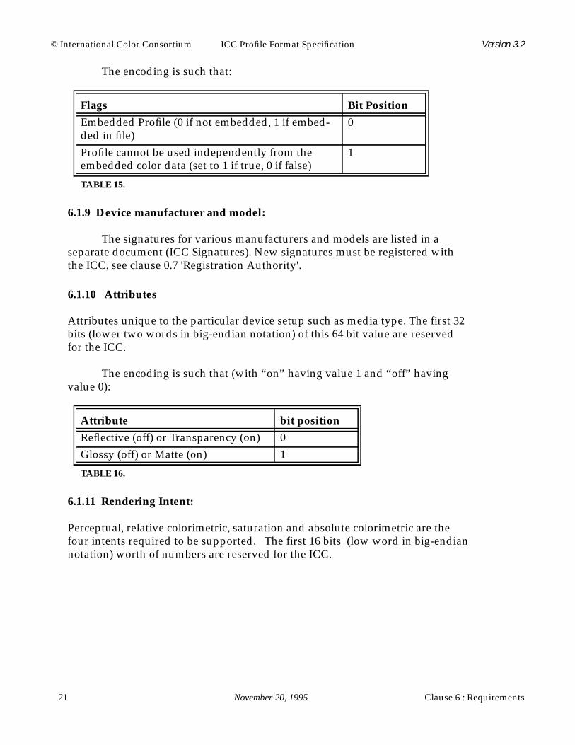
6.1.10 Attributes
Attributes unique to the particular device setup such as media type. The first 32bits (lower two words in big-endian notation) of this 64 bit value are reservedfor the ICC.
The encoding is such that (with “on” having value 1 and “off” havingvalue 0):
6.1.11 Rendering Intent:
Perceptual, relative colorimetric, saturation and absolute colorimetric are thefour intents required to be supported. The first 16 bits (low word in big-endiannotation) worth of numbers are reserved for the ICC.
Flags Bit Position
Embedded Profile (0 if not embedded, 1 if embed-ded in file)
0
Profile cannot be used independently from theembedded color data (set to 1 if true, 0 if false)
1
TABLE 15.
Attribute bit position
Reflective (off) or Transparency (on) 0Glossy (off) or Matte (on) 1
TABLE 16.

Clause 6 : Requirements November 20, 1995 22
© International Color Consortium ICC Profile Format Specification Version 3.2
The encoding is such that:
Note that this flag might not have any meaning until the profile is used insome context, e.g. in a DeviceLink or an embedded source profile.
6.1.12 Profile Creator
Identifies the creator of the profile. The signatures are from the group ofsignatures used for the device manufacturer field.
6.2 Tag Table Definition
The tag table acts as a table of contents for the tags and tag element datain the profiles. The first four bytes contain a count of the number of tags in thetable itself. The tags within the table are not required to be in any particularorder.
Individual Tag Structures Within Tag Table
6.2.1 Tag Signature
A four byte value registered with the ICC technical secretary.
6.2.2 Offset
See clause 4.8 'offset'.
Rendering Intent value
Perceptual 0Relative Colorimetric 1Saturation 2Absolute Colorimetric 3
TABLE 17.
byteoffset content
0-3 tag signature4-7 offset to beginning of tag data8-11 element size for the number of bytes in the tag data element
TABLE 18.

© International Color Consortium ICC Profile Format Specification Version 3.2
23 November 20, 1995 Clause 6 : Requirements
6.2.3 Element Size
Element size for the number of bytes in the tag data element.
6.2.4 Tag Data Requirements
All tag data is required to start on a 4-byte boundary (relative to the start of theprofile header) so that a tag starting with a 32 bit value will be properly alignedwithout the tag handler needing to know the contents of the tag. This means thatthe low 2 bits of the beginning offset must be 0. The element size should be foractual data and must not include padding at the end of the tag data.The headeris the first element in the file structure encompassing the first 128 bytes. This isimmediately followed by the tag table. Tag data elements make up the rest of thefile structures. There may be any number of tags and no particular order isrequired for the data of the tags. Each tag may have any size (up to the limitimposed by the 32 bit offsets). Exactly which tags are required or optional withwhich profiles is described under sub-clause 6.3 'Device Profile Requirements'.
6.3 Device Profile Requirements
This clause provides a top level view of what tags are required for each type ofprofile classification and a brief description of the algorithmic models associatedwith these classes. A general description for each tag is included in this clause.
Note that these descriptions assume two things; every profile contains aheader, and may include additional tags beyond those listed as required in thisclause. The explicitly listed tags are those which are required in order tocomprise a legal profile of each type.
In general, multi-dimensional tables refer to lookup tables with more thanone input component.
The intent of requiring tags with profiles is to provide a common baselevel of functionality. If a custom CMM is not present, then the default CMMwill have enough information to perform the requested color transformations.The particular models implied by the required data are also described below.While this data might not provide the highest level of quality obtainable withoptional data and private data, the data provided is adequate for sophisticateddevice modeling.
The interpretation of some tags are context dependent. This dependency

Clause 6 : Requirements November 20, 1995 24
© International Color Consortium ICC Profile Format Specification Version 3.2
is described below in Table 19 .
6.3.1 Input Profile
This profile represents input devices such as scanners and digital cameras.
6.3.1.1 Monochrome Input Profiles
The mathematical model implied by this data is
. This represents a simple tone
reproduction curve adequate for most monochrome input devices. Theconnection values in this equation should represent the achromatic channel ofthe profile connection space. If the inverse of this is desired, then the following
equation is used, .
Multidimensional tables are not allowed to be included in monochromeprofiles.
Profile Tag Name Interpretation
Input Profile AToB0Tag noneDisplay Profile AToB0Tag noneOutput Profile BToA0Tag perceptual renderingOutput Profile BToA1Tag colorimetric renderingOutput Profile BToA2Tag saturation renderingInput Profile grayTRCTag depends on intentDisplay Profile grayTRCTag additiveOutput Profile grayTRCTag subtractive
TABLE 19.
Tag Name General Description
profileDescriptionTag Structure containing invariant and localizableversions of the profile name for display
grayTRCTag Gray tone reproduction curve (TRC)mediaWhitePointTag Media XYZ white pointcopyrightTag 7 bit ASCII profile copyright information
TABLE 20.
connection grayTRC device[ ]=
device grayTRC1–
connection[ ]=

© International Color Consortium ICC Profile Format Specification Version 3.2
25 November 20, 1995 Clause 6 : Requirements
6.3.1.2 RGB Input Profiles
The forward mathematical model implied by this data is:
This represents a simple linearization followed by a linear mixing model.The three tone reproduction curves linearize the raw values with respect to theluminance (Y) dimension of the CIEXYZ encoding of the profile connectionspace. The 3x3 matrix converts these linearized values into XYZ values for theCIEXYZ encoding of the profile connection space. The inverse model is given by
Tag Name General Description
profileDescriptionTag Structure containing invariant and localizableversions of the profile name for display
redColorantTag Red colorant XYZ relative tristimulus valuesgreenColorantTag Green colorant XYZ relative tristimulus valuesblueColorantTag Blue colorant XYZ relative tristimulus valuesredTRCTag Red channel tone reproduction curvegreenTRCTag Green channel tone reproduction curveblueTRCTag Blue channel tone reproduction curvemediaWhitePointTag Media XYZ white pointcopyrightTag 7 bit ASCII profile copyright information
TABLE 21.
linearr redTRC devicer[ ]=
linearg greenTRC deviceg[ ]=
linearb blueTRC deviceb[ ]=
connectionXconnectionYconnectionZ
redColorantX greenColorantX blueColorantXredColorantY greenColorantY blueColorantYredColorantZ greenColorantZ blueColorantZ
linearr
linearg
linearb
=

Clause 6 : Requirements November 20, 1995 26
© International Color Consortium ICC Profile Format Specification Version 3.2
the following equation,
Only the CIEXYZ encoding of the profile connection space can be usedwith matrix/TRC models. A multidimensional table tag must be included if theCIELAB encoding of the profile connection space is to be used.
6.3.1.3 CMYK Input Profiles
The AToB0Tag represents a device model described by the lut8Type orlut16Types. This tag provides the parameter data for an algorithm that includesa set of non-interdependent per-channel tone reproduction curves, a multi-dimensional lookup table and a set of non-interdependent per-channellinearization curves. The mathematical model implied by this data is describedin detail in clauses 6.5.4 and 6.5.5 that specify the general lookup table tagelement structures.
6.3.2 Display Profile
This profile represents display devices such as monitors.
Tag Name General Description
profileDescriptionTag Structure containing invariant and localizableversions of the profile name for display
AToB0Tag Device to PCS: 8 or 16 bit datamediaWhitePointTag Media XYZ white pointcopyrightTag 7 bit ASCII profile copyright information
TABLE 22.
linearr
linearg
linearb
redColorantX greenColorantX blueColorantXredColorantY greenColorantY blueColorantYredColorantZ greenColorantZ blueColorantZ
1–connectionXconnectionYconnectionZ
=
devicer redTRC1–
linearr[ ]=
deviceg greenTRC1–
linearg[ ]=
deviceb blueTRC1–
linearb[ ]=

© International Color Consortium ICC Profile Format Specification Version 3.2
27 November 20, 1995 Clause 6 : Requirements
6.3.2.1 Monochrome Display Profiles
The mathematical model implied by this data is
.
This represents a simple tone reproduction curve adequate for mostmonochrome display devices. The connection values in this equation shouldrepresent the achromatic channel of the profile connection space. If the inverseof this is desired, then the following equation is used,
.
Multidimensional tables are not allowed to be included in monochromeprofiles.
6.3.2.2 RGB Display Profiles
This model is based on a three non-interdependent per-channel tone
Tag Name General Description
profileDescriptionTag Structure containing invariant and localizableversions of the profile name for display
grayTRCTag Gray tone reproduction curvemediaWhitePointTag Media XYZ white pointcopyrightTag 7 bit ASCII profile copyright information
TABLE 23.
Tag Name General Description
profileDescriptionTag Structure containing invariant and localizableversions of the profile name for display
redColorantTag Relative XYZ values of red phosphorgreenColorantTag Relative XYZ values of green phosphorblueColorantTag Relative XYZ values of blue phosphorredTRCTag Red channel tone reproduction curvegreenTRCTag Green channel tone reproduction curveblueTRCTag Blue channel tone reproduction curvemediaWhitePointTag Media XYZ white pointcopyrightTag 7 bit ASCII profile copyright information
TABLE 24.
connection grayTRC device[ ]=
device grayTRC1–
connection[ ]=
Clause 6 : Requirements November 20, 1995 28
© International Color Consortium ICC Profile Format Specification Version 3.2
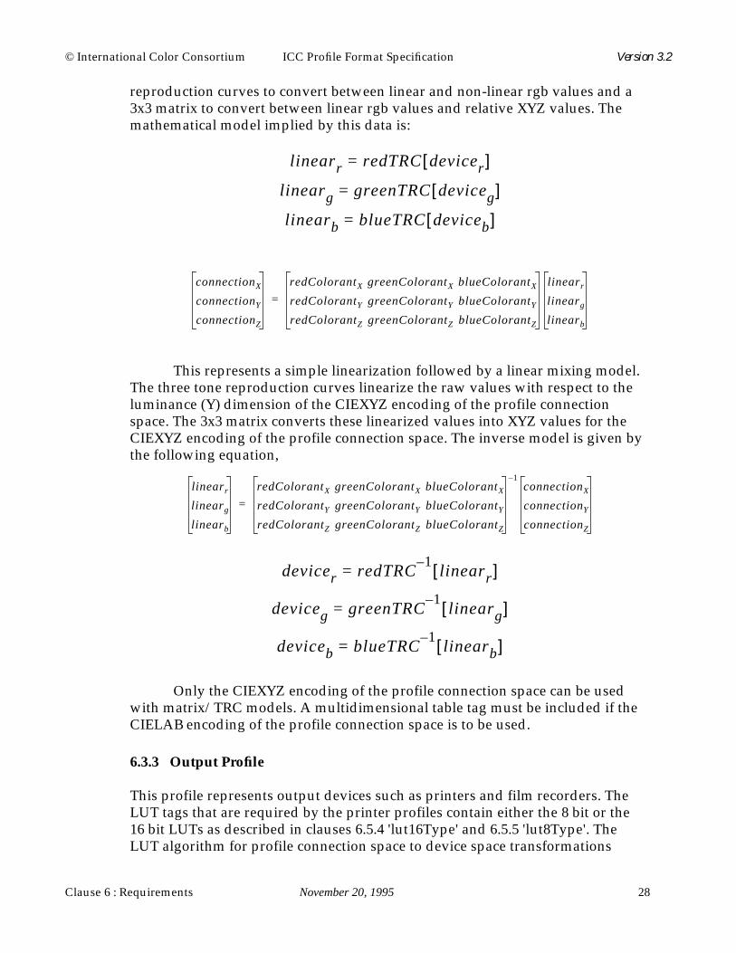
reproduction curves to convert between linear and non-linear rgb values and a3x3 matrix to convert between linear rgb values and relative XYZ values. Themathematical model implied by this data is:
This represents a simple linearization followed by a linear mixing model.The three tone reproduction curves linearize the raw values with respect to theluminance (Y) dimension of the CIEXYZ encoding of the profile connectionspace. The 3x3 matrix converts these linearized values into XYZ values for theCIEXYZ encoding of the profile connection space. The inverse model is given bythe following equation,
Only the CIEXYZ encoding of the profile connection space can be usedwith matrix/TRC models. A multidimensional table tag must be included if theCIELAB encoding of the profile connection space is to be used.
6.3.3 Output Profile
This profile represents output devices such as printers and film recorders. TheLUT tags that are required by the printer profiles contain either the 8 bit or the16 bit LUTs as described in clauses 6.5.4 'lut16Type' and 6.5.5 'lut8Type'. TheLUT algorithm for profile connection space to device space transformations
linearr redTRC devicer[ ]=
linearg greenTRC deviceg[ ]=
linearb blueTRC deviceb[ ]=
connectionXconnectionYconnectionZ
redColorantX greenColorantX blueColorantXredColorantY greenColorantY blueColorantYredColorantZ greenColorantZ blueColorantZ
linearr
linearg
linearb
=
linearr
linearg
linearb
redColorantX greenColorantX blueColorantXredColorantY greenColorantY blueColorantYredColorantZ greenColorantZ blueColorantZ
1–connectionXconnectionYconnectionZ
=
devicer redTRC1–
linearr[ ]=
deviceg greenTRC1–
linearg[ ]=
deviceb blueTRC1–
linearb[ ]=

© International Color Consortium ICC Profile Format Specification Version 3.2
29 November 20, 1995 Clause 6 : Requirements
process data sequentially through a matrix, input tables, a color LUT, andoutput tables.
6.3.3.1 Monochrome Output Profiles
The mathematical model implied by this data is
.
This represents a simple tone reproduction curve adequate for mostmonochrome output devices. The connection values in this equation shouldrepresent the achromatic channel of the profile connection space. If the inverseof this is desired, then the following equation is used,
.
Multidimensional tables are not allowed to be included in monochromeprofiles.
Tag Name General Description
profileDescriptionTag Structure containing invariant and localizableversions of the profile name for display
grayTRCTag Gray tone reproduction curvemediaWhitePointTag Media XYZ white pointcopyrightTag 7 bit ASCII profile copyright information
TABLE 25.
connection grayTRC device[ ]=
device grayTRC1–
connection[ ]=
Clause 6 : Requirements November 20, 1995 30
© International Color Consortium ICC Profile Format Specification Version 3.2
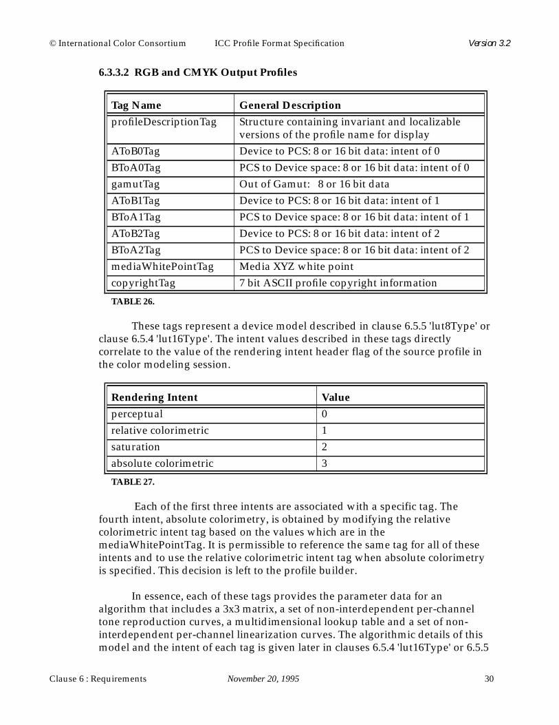
6.3.3.2 RGB and CMYK Output Profiles
These tags represent a device model described in clause 6.5.5 'lut8Type' orclause 6.5.4 'lut16Type'. The intent values described in these tags directlycorrelate to the value of the rendering intent header flag of the source profile inthe color modeling session.
Each of the first three intents are associated with a specific tag. Thefourth intent, absolute colorimetry, is obtained by modifying the relativecolorimetric intent tag based on the values which are in themediaWhitePointTag. It is permissible to reference the same tag for all of theseintents and to use the relative colorimetric intent tag when absolute colorimetryis specified. This decision is left to the profile builder.
In essence, each of these tags provides the parameter data for analgorithm that includes a 3x3 matrix, a set of non-interdependent per-channeltone reproduction curves, a multidimensional lookup table and a set of non-interdependent per-channel linearization curves. The algorithmic details of thismodel and the intent of each tag is given later in clauses 6.5.4 'lut16Type' or 6.5.5
Tag Name General Description
profileDescriptionTag Structure containing invariant and localizableversions of the profile name for display
AToB0Tag Device to PCS: 8 or 16 bit data: intent of 0BToA0Tag PCS to Device space: 8 or 16 bit data: intent of 0gamutTag Out of Gamut: 8 or 16 bit dataAToB1Tag Device to PCS: 8 or 16 bit data: intent of 1BToA1Tag PCS to Device space: 8 or 16 bit data: intent of 1AToB2Tag Device to PCS: 8 or 16 bit data: intent of 2BToA2Tag PCS to Device space: 8 or 16 bit data: intent of 2mediaWhitePointTag Media XYZ white pointcopyrightTag 7 bit ASCII profile copyright information
TABLE 26.
Rendering Intent Value
perceptual 0relative colorimetric 1saturation 2absolute colorimetric 3
TABLE 27.

© International Color Consortium ICC Profile Format Specification Version 3.2
31 November 20, 1995 Clause 6 : Requirements
'lut8Type' that specify the general lookup table tag element structures.
6.3.4 Additional Profile Formats
6.3.4.1 DeviceLink Profile
This profile represents a one-way link or connection between devices. It does notrepresent any device model nor can it be embedded into images.
The single AToB0Tag may contain any of the four possible renderingintents. The rendering intent used is indicated in the header of the profile.
The AToB0Tag represents a device model described in clause 6.5.4'lut16Type' or clause 6.5.5 'lut8Type'. This tag provides the parameter data for analgorithm that includes a 3x3 matrix, a set of non-interdependent per-channeltone reproduction curves, a multidimensional lookup table and a set of non-interdependent per-channel linearization curves. The algorithmic details of thismodel and the intent of each tag is given later in clauses 6.5.4 'lut16Type' and6.5.5 'lut8Type' that specify the general lookup table tag element structures. Thisis a pre-evaluated transform that cannot be undone.
The color space of data in the DeviceLink profile will be the same as thecolor space of the data of the first profile in the sequence. The profile connectionspace will be the same as the color space of the data of the last profile in thesequence.
6.3.4.2 ColorSpaceConversion Profile
This profile provides the relevant information to perform a color spacetransformation between the non-device color spaces and the PCS. It does not
Tag Name General Description
profileDescriptionTag Structure containing invariant and localizable ver-sions of the profile name for display
AToB0Tag Actual transformation parameter structure (this isan exclusive or) 8 or 16 bit data
profileSequence-DescTag
An array of descriptions of the profile sequence
copyrightTag 7 bit ASCII profile copyright information
TABLE 28.
Clause 6 : Requirements November 20, 1995 32
© International Color Consortium ICC Profile Format Specification Version 3.2
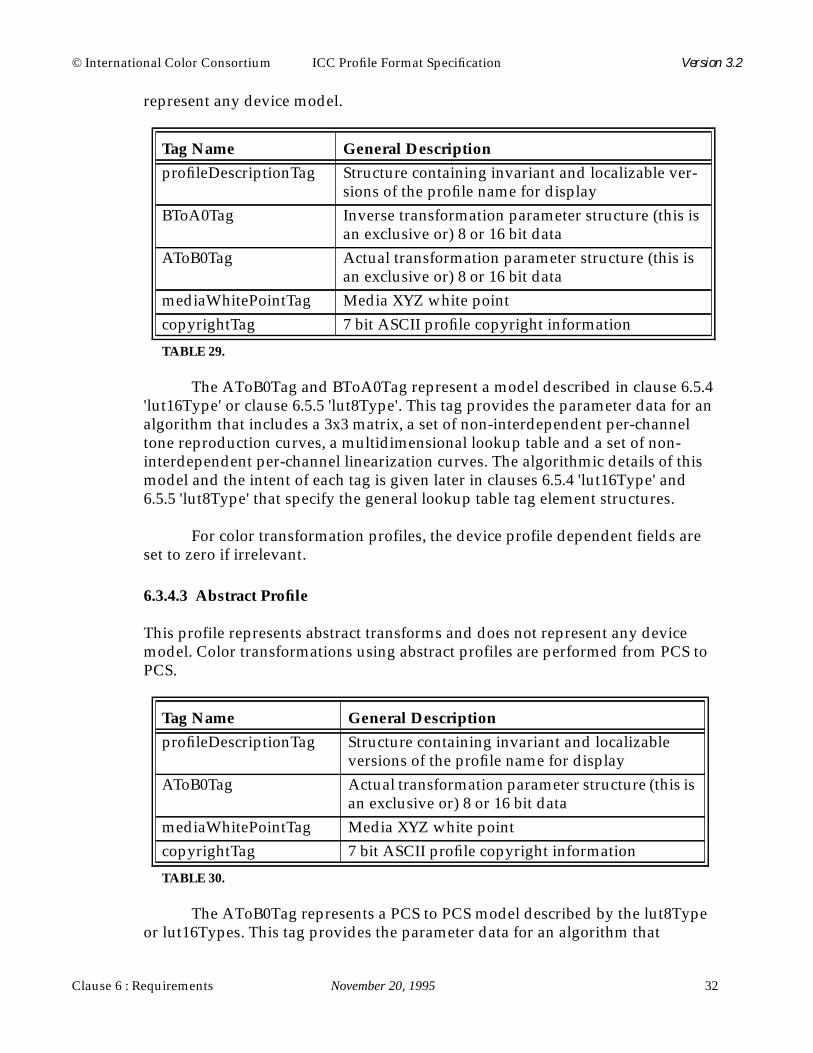
represent any device model.
The AToB0Tag and BToA0Tag represent a model described in clause 6.5.4'lut16Type' or clause 6.5.5 'lut8Type'. This tag provides the parameter data for analgorithm that includes a 3x3 matrix, a set of non-interdependent per-channeltone reproduction curves, a multidimensional lookup table and a set of non-interdependent per-channel linearization curves. The algorithmic details of thismodel and the intent of each tag is given later in clauses 6.5.4 'lut16Type' and6.5.5 'lut8Type' that specify the general lookup table tag element structures.
For color transformation profiles, the device profile dependent fields areset to zero if irrelevant.
6.3.4.3 Abstract Profile
This profile represents abstract transforms and does not represent any devicemodel. Color transformations using abstract profiles are performed from PCS toPCS.
The AToB0Tag represents a PCS to PCS model described by the lut8Typeor lut16Types. This tag provides the parameter data for an algorithm that
Tag Name General Description
profileDescriptionTag Structure containing invariant and localizable ver-sions of the profile name for display
BToA0Tag Inverse transformation parameter structure (this isan exclusive or) 8 or 16 bit data
AToB0Tag Actual transformation parameter structure (this isan exclusive or) 8 or 16 bit data
mediaWhitePointTag Media XYZ white pointcopyrightTag 7 bit ASCII profile copyright information
TABLE 29.
Tag Name General Description
profileDescriptionTag Structure containing invariant and localizableversions of the profile name for display
AToB0Tag Actual transformation parameter structure (this isan exclusive or) 8 or 16 bit data
mediaWhitePointTag Media XYZ white pointcopyrightTag 7 bit ASCII profile copyright information
TABLE 30.

© International Color Consortium ICC Profile Format Specification Version 3.2
33 November 20, 1995 Clause 6 : Requirements
includes a 3x3 matrix, a set of non-interdependent per-channel tonereproduction curves, a multidimensional lookup table and a set of non-interdependent per-channel linearization curves. The algorithmic details of thismodel and the intent of each tag is given later in clauses 6.5.4 'lut16Type' and6.5.5 'lut8Type' that specify the general lookup table tag element structures.
6.3.4.4 Named Color Profile
This profile class is designated by setting the header’s “Profile/Deviceclass” field to ‘nmcl’. Named color profiles can be thought of as sibling profilesto device profiles. For a given device there would be one or more device profilesto handle process color conversions and one or more named color profiles tohandle named colors. There might be multiple named color profiles to accountfor different consumables or multiple named color vendors.
This profile provides a PCS and optional device representation for a list ofnamed colors. Named color profiles are device-specific in that their data isshaped for a particular device.
The namedColor2Tag provides a PCS and optional device representationfor each named color in a list of named colors. The PCS representation isprovided to support general color management functionality. It is very usefulfor display and emulation of the named colors.
When using a named color profile with the device for which it isintended, the device representation of the color specifies the exact devicecoordinates for each named color. The PCS representation in conjunction withthe device's output profile can provide an approximation of these exactcoordinates. The exactness of this approximation is a function of the accuracy ofthe output profile and the color management system performing thetransformations.
The combination of the PCS and device representations provides for flexibilitywith respect to accuracy and portability.
Tag Name General Description
profileDescriptionTag Structure containing invariant and localizableversions of the profile name for display
namedColor2Tag PCS and optional device representation fornamed colors
mediaWhitePointTag Media XYZ white pointcopyrightTag 7 bit ASCII profile copyright information
TABLE 31.

Clause 6 : Requirements November 20, 1995 34
© International Color Consortium ICC Profile Format Specification Version 3.2
6.4 Tag Descriptions
This clause specifies the individual tags used to create all possible portableprofiles in the ICC Profile Format. The appropriate tag typing is indicated witheach individual tag description. Note that the signature indicates only the typeof data and does not imply anything about the use or purpose for which the datais intended.
In addition to the tags listed below, any of the previously defined tags inclause 6.3 'Device Profile Requirements' can also be used as optional tags if theyare not used in the required set for a particular profile and are not specificallyexcluded in a profile definition.
Tag Name General Description
AToB0Tag Multidimensional transformation structureAToB1Tag Multidimensional transformation structureAToB2Tag Multidimensional transformation structureblueColorantTag Relative XYZ values of blue phosphor or colorantblueTRCTag Blue channel tone reproduction curveBToA0Tag Multidimensional transformation structureBToA1Tag Multidimensional transformation structureBToA2Tag Multidimensional transformation structurecalibrationDateTimeTag Profile calibration date and timecharTargetTag Characterization target such as IT8/7.2copyrightTag 7 bit ASCII profile copyright informationdeviceMfgDescTag displayable description of device manufacturerdeviceModelDescTag displayable description of device modelgamutTag Out of Gamut: 8 or 16 bit datagrayTRCTag Gray tone reproduction curvegreenColorantTag Relative XYZ values of green phosphor or colo-
rantgreenTRCTag Green channel tone reproduction curveluminanceTag Absolute luminance for emissive devicemeasurementTag Alternative measurement specification informa-
tionmediaBlackPointTag Media XYZ black pointmediaWhitePointTag Media XYZ white pointpreview0Tag Preview transformation: 8 or 16 bit data
TABLE 32.

© International Color Consortium ICC Profile Format Specification Version 3.2
35 November 20, 1995 Clause 6 : Requirements
6.4.1 AToB0Tag
Tag Type : lut8Type xor lut16TypeTag Signature : ‘A2B0’ 41324230h
Device to PCS: 8 bit or 16 bit data. The processing mechanisms are described inclauses 6.5.4 'lut16Type' and 6.5.5 'lut8Type'.
6.4.2 AToB1Tag
Tag Type : lut8Type xor lut16TypeTag Signature : ‘A2B1’ 41324231h
preview1Tag Preview transformation: 8 or 16 bit datapreview2Tag Preview transformation: 8 or 16 bit dataprofileDescriptionTag profile description for displayprofileSequence-DescTag
profile sequence description from source to desti-nation
ps2CRD0Tag PostScript Level 2 color rendering dictionary: per-ceptual
ps2CRD1Tag PostScript Level 2 color rendering dictionary: col-orimetric
ps2CRD2Tag PostScript Level 2 color rendering dictionary: sat-uration
ps2CRD3Tag PostScript Level 2 color rendering dictionary:absolute
ps2CSATag PostScript Level 2 color space arrayps2RenderingIntentTag PostScript Level 2 Rendering IntentredColorantTag Relative XYZ values of red phosphor or colorantredTRCTag Red channel tone reproduction curvescreeningDescTag Screening attributes descriptionscreeningTag Screening attributes such as frequency, angle and
spottechnologyTag Device technology information such as LCD,
CRT, Dye Sublimation, etc.ucrbgTag Under color removal and black generation
descriptionviewingCondDescTag Specifies viewing condition descriptionviewingConditionsTag Specifies viewing condition parameters
TABLE 32.

Clause 6 : Requirements November 20, 1995 36
© International Color Consortium ICC Profile Format Specification Version 3.2
Device to PCS: 8 bit or 16 bit data. The processing mechanisms are described inclauses 6.5.4 'lut16Type' and 6.5.5 'lut8Type'.
6.4.3 AToB2Tag
Tag Type : lut8Type xor lut16TypeTag Signature : ‘A2B2’ 41324232h
Device to PCS: 8 bit or 16 bit data. The processing mechanisms are described inclauses 6.5.4 'lut16Type' and 6.5.5 'lut8Type'.
6.4.4 blueColorantTag
Tag Type : XYZTypeTag Signature : ‘bXYZ’ 6258595Ah
The relative XYZ values of blue phosphor or colorant.
6.4.5 blueTRCTag
Tag Type : curveTypeTag Signature : ‘bTRC’ 62545243h
Blue channel tone reproduction curve. The first element represents no colorant(white) or phosphors (black) and the last element represents 100 percent colorant(blue) or 100 percent phosphor (blue).
The count value specifies the number of entries in the curve table exceptas follows:
when count is 0, then a linear response (slope equal to 1.0) is assumed,
when count is 1, then the data entry is interpreted as a simple gammavalue encoded as a u8Fixed8Number.
Gamma is interpreted canonically and NOT as an inverse.
6.4.6 BToA0Tag
Tag Type : lut8Type xor lut16TypeTag Signature : ‘B2A0’ 42324130h
PCS to Device space: 8 bit or 16 bit data. The processing mechanisms aredescribed in clauses 6.5.4 'lut16Type' and 6.5.5 'lut8Type'.

© International Color Consortium ICC Profile Format Specification Version 3.2
37 November 20, 1995 Clause 6 : Requirements
6.4.7 BToA1Tag
Tag Type : lut8Type xor lut16TypeTag Signature : ‘B2A1’ 42324131h
PCS to Device space: 8 bit or 16 bit data. The processing mechanisms aredescribed in clauses 6.5.4 'lut16Type' and 6.5.5 'lut8Type'.
6.4.8 BToA2Tag
Tag Type : lut8Type xor lut16TypeTag Signature : ‘B2A2’ 42324132h
PCS to Device space: 8 bit or 16 bit data. The processing mechanisms aredescribed in clauses 6.5.4 'lut16Type' and 6.5.5 'lut8Type'.
6.4.9 calibrationDateTimeTag
Tag Type : dateTimeTypeTag Signature : ‘calt’ 63616C74h
Profile calibration date and time. Initially, this tag matches the contents of thecreationDateTime header flag. This allows applications and utilities to verify ifthis profile matches a vendor’s profile and how recently calibration has beenperformed.
6.4.10 charTargetTag
Tag Type : textTypeTag Signature : ‘targ’ 74617267h
This tag contains the measurement data for a characterization target such asIT8.7/2. This tag is provided so that distributed utilities can create transforms“on the fly” or check the current performance against the original deviceperformance. The tag embeds the exact data file format defined in the ANSI orISO standard which is applicable to the device being characterized.
Examples are the data formats described in ANSI IT8.7/1-1993 section4.10, ANSI IT8.7/2-1993 section 4.10 and ANSI IT8.7/3 section 4.10. Each ofthese file formats contains an identifying character string as the first few bytes ofthe format, allowing an external parser to determine which data file format isbeing used. This provides the facilities to include a wide range of targets using avariety of measurement specifications in a standard manner.
Note: The IT8 specifications do not currently have a keyword which

Clause 6 : Requirements November 20, 1995 38
© International Color Consortium ICC Profile Format Specification Version 3.2
identifies the set as being reference data as opposed to device responsedata. An addition to enable this additional data set is being considered bythe IT8 committee.
6.4.11 copyrightTag
Tag Type : textTypeTag Signature : ‘cprt’ 63707274h
This tag contains the 7 bit ASCII text copyright information for the profile.
6.4.12 deviceMfgDescTag
Tag Type : textDescriptionTypeTag Signature : ‘dmnd’ 646D6E64h
Structure containing invariant and localizable versions of the devicemanufacturer for display. The content of this structure is described in clause6.5.13 'textDescriptionType'.
6.4.13 deviceModelDescTag
Tag Type : textDescriptionTypeTag Signature : ‘dmdd’ 646D6464h
Structure containing invariant and localizable versions of the device model fordisplay. The content of this structure is described in clause 6.5.13'textDescriptionType'.
6.4.14 gamutTag
Tag Type : lut8Type xor lut16TypeTag Signature : ‘gamt’ 67616D74h
Out of Gamut tag: 8 bit or 16 bit data. The processing mechanisms are describedin clauses 6.5.4 'lut16Type' and 6.5.5 'lut8Type'.
The CLUT tag has a single output. If the output value is 0, the input coloris in gamut. If the output is non-zero, the input color is out of gamut, with thenumber “n+1” being at least as far out of the gamut as the number “n”.
6.4.15 grayTRCTag
Tag Type : curveTypeTag Signature : ‘kTRC’ 6B545243h

© International Color Consortium ICC Profile Format Specification Version 3.2
39 November 20, 1995 Clause 6 : Requirements
Gray tone reproduction curve. The tone reproduction curve provides thenecessary information to convert between a single device channel and theCIEXYZ encoding of the profile connection space. The first element representsno colorant (white) or phosphors (black) and the last element represents 100percent colorant (black) or 100 percent phosphor (white).
The count value specifies the number of entries in the curve table exceptas follows:
when count is 0, then a linear response (slope equal to 1.0) is assumed,
when count is 1, then the data entry is interpreted as a simple gammavalue encoded as a u8Fixed8Number.
Gamma is interpreted canonically and NOT as an inverse.
6.4.16 greenColorantTag
Tag Type : XYZTypeTag Signature : ‘gXYZ’ 6758595Ah
Relative XYZ values of green phosphor or colorant.
6.4.17 greenTRCTag
Tag Type : curveTypeTag Signature : ‘gTRC’ 67545243h
Green channel tone reproduction curve. The first element represents nocolorant (white) or phosphors (black) and the last element represents 100 percentcolorant (green) or 100 percent phosphor (green).
The count value specifies the number of entries in the curve table exceptas follows:
when count is 0, then a linear response (slope equal to 1.0) is assumed,
when count is 1, then the data entry is interpreted as a simple gammavalue encoded as a u8Fixed8Number.
Gamma is interpreted canonically and NOT as an inverse.
6.4.18 luminanceTag
Tag Type : XYZType

Clause 6 : Requirements November 20, 1995 40
© International Color Consortium ICC Profile Format Specification Version 3.2
Tag Signature : ‘lumi’ 6C756D69h
Absolute luminance of devices is in candelas per meter squared as described bythe Y channel. The X and Z channels are ignored in all cases.
6.4.19 measurementTag
Tag Type : measurementTypeTag Signature : ‘meas’ 6D656173h
Alternative measurement specification such as a D65 illuminant instead of thedefault D50.
6.4.20 mediaBlackPointTag
Tag Type : XYZTypeTag Signature : ‘bkpt’ 626b7074h
This tag specifies the media black point and is used for generating absolutecolorimetry. It is referenced to the profile connection space so that the mediablack point as represented in the PCS is equivalent to this tag value. If this tag isnot present, it is assumed to be (0,0,0).
6.4.21 mediaWhitePointTag
Tag Type : XYZTypeTag Signature : ‘wtpt’ 77747074h
This tag specifies the media white point and is used for generating absolutecolorimetry. It is referenced to the profile connection space so that the mediawhite point as represented in the PCS is equivalent to this tag value.
6.4.22 namedColorTag
Tag Type : namedColorTypeTag Signature : ‘ncol’ 6E636F6Ch
NOTE: This tag is obsolete, and should not be used in new profiles. UsenamedColor2Tag instead.
Named color reference transformation for converting between namedcolor sets and the profile connection space or device color spaces.
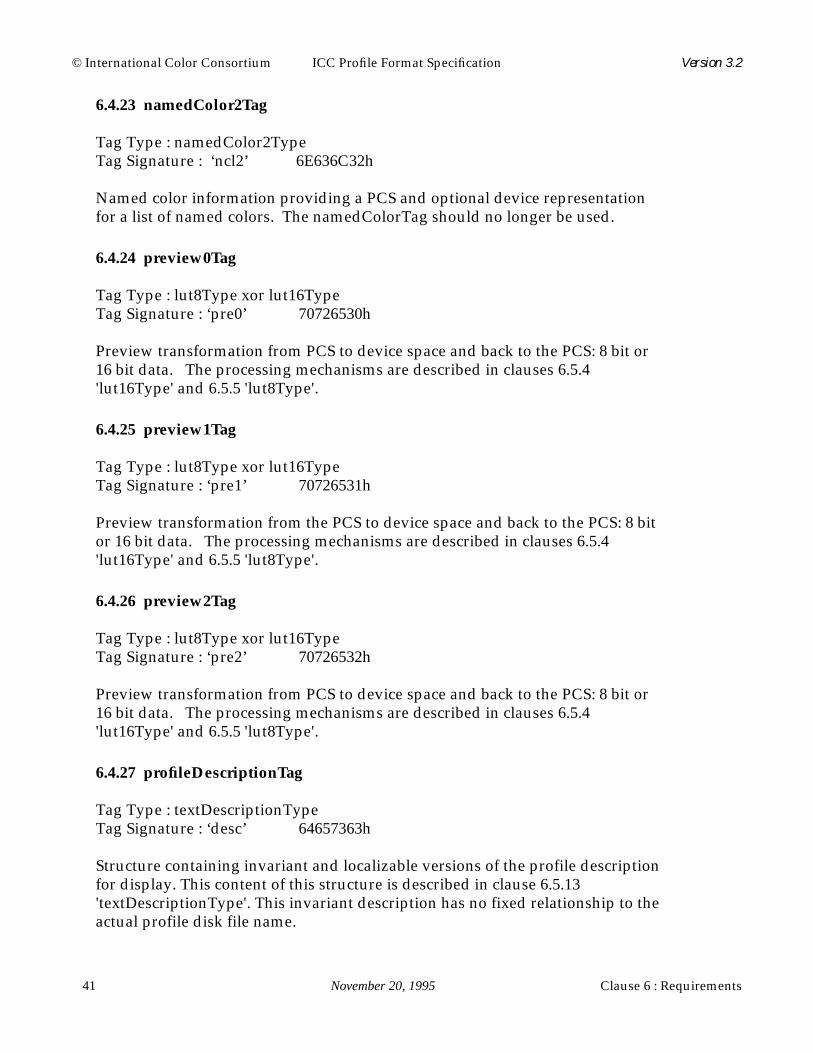
© International Color Consortium ICC Profile Format Specification Version 3.2
41 November 20, 1995 Clause 6 : Requirements
6.4.23 namedColor2Tag
Tag Type : namedColor2TypeTag Signature : ‘ncl2’ 6E636C32h
Named color information providing a PCS and optional device representationfor a list of named colors. The namedColorTag should no longer be used.
6.4.24 preview0Tag
Tag Type : lut8Type xor lut16TypeTag Signature : ‘pre0’ 70726530h
Preview transformation from PCS to device space and back to the PCS: 8 bit or16 bit data. The processing mechanisms are described in clauses 6.5.4'lut16Type' and 6.5.5 'lut8Type'.
6.4.25 preview1Tag
Tag Type : lut8Type xor lut16TypeTag Signature : ‘pre1’ 70726531h
Preview transformation from the PCS to device space and back to the PCS: 8 bitor 16 bit data. The processing mechanisms are described in clauses 6.5.4'lut16Type' and 6.5.5 'lut8Type'.
6.4.26 preview2Tag
Tag Type : lut8Type xor lut16TypeTag Signature : ‘pre2’ 70726532h
Preview transformation from PCS to device space and back to the PCS: 8 bit or16 bit data. The processing mechanisms are described in clauses 6.5.4'lut16Type' and 6.5.5 'lut8Type'.
6.4.27 profileDescriptionTag
Tag Type : textDescriptionTypeTag Signature : ‘desc’ 64657363h
Structure containing invariant and localizable versions of the profile descriptionfor display. This content of this structure is described in clause 6.5.13'textDescriptionType'. This invariant description has no fixed relationship to theactual profile disk file name.
Clause 6 : Requirements November 20, 1995 42
© International Color Consortium ICC Profile Format Specification Version 3.2
6.4.28 profileSequenceDescTag
Tag Type : profileSequenceDescTypeTag Signature : ‘pseq’ 70736571h
Structure containing a description of the profile sequence from source todestination, typically used with the devicelink profile. This content of thisstructure is described in clause 6.5.9 'profileSequenceDescType'.
6.4.29 ps2CRD0Tag
Tag Type : dataTypeTag Signature : ‘psd0’ 70736430h
PostScript Level 2 Type 1 color rendering dictionary (CRD) for the Perceptualrendering intent. This tag provides the dictionary operand to thesetcolorrendering operator. This tag can be used in conjunction with thesetcolorrendering operator on any PostScript Level 2 device.
See Annex D : 'PostScript Level 2 Tags', for the relationship between theICC profile data and PostScript Tags.
6.4.30 ps2CRD1Tag
Tag Type : dataTypeTag Signature : ‘psd1’ 70736431h
PostScript Level 2 Type 1 CRD for the RelativeColorimetric rendering intent.This tag provides the dictionary operand to the setcolorrendering operator. Thistag can be used in conjunction with the setcolorrendering operator on anyPostScript Level 2 device.
See Annex D : 'PostScript Level 2 Tags', for the relationship between theICC profile data and PostScript Tags.
6.4.31 ps2CRD2Tag
Tag Type : dataTypeTag Signature : ‘psd2’ 70736432h
PostScript Level 2 Type 1 CRD for the Saturation rendering intent. This tagprovides the dictionary operand to the setcolorrendering operator. This tag canbe used in conjunction with the setcolorrendering operator on any PostScriptLevel 2 device.

© International Color Consortium ICC Profile Format Specification Version 3.2
43 November 20, 1995 Clause 6 : Requirements
See Annex D : 'PostScript Level 2 Tags', for the relationship between theICC profile data and PostScript Tags.
6.4.32 ps2CRD3Tag
Tag Type : dataTypeTag Signature : ‘psd3’ 70736433h
PostScript Level 2 Type 1 CRD for the AbsoluteColorimetric rendering intent.This tag provides the dictionary operand to the setcolorrendering operator. Thistag can be used in conjunction with the setcolorrendering operator on anyPostScript Level 2 device.
See Annex D : 'PostScript Level 2 Tags', for the relationship between theICC profile data and PostScript Tags.
6.4.33 ps2CSATag
Tag Type : dataTypeTag Signature : ‘ps2s’ 70733273h
PostScript Level 2 color space array. This tag provides the array operand to thesetcolorspace operator. For color spaces that fit within the original PostScriptLevel 2 device independent color model no operator verification need beperformed. For color spaces that fit only within extensions to this model,operator verification is first required. An example of this would be forCalibrated CMYK input color spaces which are supported via an extension. Insuch cases where the necessary PostScript Level 2 support is not available,PostScript Level 1 color spaces, such as DeviceCMYK, can be used, or the colorscan be converted on the host using a CMS. In the latter case, the PostScript Level1 color operators are used to specify the device dependent (pre-converted)colors. The PostScript contained in this tag expects the associated color valuesinstantiated either through setcolor or image to be in the range [0, 1].
See Annex D : 'PostScript Level 2 Tags', for the relationship between theICC profile data and PostScript Tags.
6.4.34 ps2RenderingIntentTag
Tag Type : dataTypeTag Signature : ‘ps2i’ 70733269h
PostScript Level 2 rendering intent. This tag provides the operand to thefindcolorrendering operator. findcolorrendering is not necessarily supported onall PostScript Level 2 devices, hence its existence must first be established.

Clause 6 : Requirements November 20, 1995 44
© International Color Consortium ICC Profile Format Specification Version 3.2
Standard values for ps2RenderingIntentTag are RelativeColorimetric,AbsoluteColorimetric, Perceptual, and Saturation. These intents are meant tocorrespond to the rendering intents of the profile's header.
See Annex D : 'PostScript Level 2 Tags', for the relationship between theICC profile data and PostScript Tags.
6.4.35 redColorantTag
Tag Type : XYZTypeTag Signature : ‘rXYZ’ 7258595Ah
Relative XYZ values of red phosphor or colorant.
6.4.36 redTRCTag
Tag Type : curveTypeTag Signature : ‘rTRC’ 72545243h
Red channel tone reproduction curve. The first element represents no colorant(white) or phosphors (black) and the last element represents 100 percent colorant(red) or 100 percent phosphor (red).
The count value specifies the number of entries in the curve table exceptas follows:
when count is 0, then a linear response (slope equal to 1.0) is assumed,
when count is 1, then the data entry is interpreted as a simple gammavalue encoded as a u8Fixed8Number.
Gamma is interpreted canonically and NOT as an inverse.
6.4.37 screeningDescTag
Tag Type : textDescriptionTypeTag Signature : ‘scrd’ 73637264h
Structure containing invariant and localizable versions of the screeningconditions. This content of this structure is described in clause 6.5.13'textDescriptionType'.
6.4.38 screeningTag
Tag Type : screeningType

© International Color Consortium ICC Profile Format Specification Version 3.2
45 November 20, 1995 Clause 6 : Requirements
Tag Signature : ‘scrn’ 7363726Eh
This tag contains screening information for a variable number of channels.
6.4.39 technologyTag
Tag Type : signatureTypeTag Signature : ‘tech’ 74656368h
Device technology information such as CRT, Dye Sublimation, etc. The encodingis such that:
Technology signature hex signature
Film Scanner ‘fscn’ 6673636EhDigital Camera ‘dcam’ 6463616DhReflective Scanner ‘rscn’ 7273636EhInk Jet Printer ‘ijet’ 696A6574hThermal Wax Printer ‘twax’ 74776178hElectrophotographic Printer ‘epho’ 6570686FhElectrostatic Printer ‘esta’ 65737461hDye Sublimation Printer ‘dsub’ 64737562hPhotographic Paper Printer ‘rpho’ 7270686FhFilm Writer ‘fprn’ 6670726EhVideo Monitor ‘vidm’ 7669646DhVideo Camera ‘vidc’ 76696463hProjection Television ‘pjtv’ 706A7476hCathode Ray Tube Display ‘CRT ‘ 43525420hPassive Matrix Display ‘PMD ‘ 504D4420hActive Matrix Display ‘AMD ‘ 414D4420hPhoto CD ‘KPCD’ 4B504344hPhotoImageSetter ‘imgs’ 696D6773hGravure ‘grav’ 67726176hOffset Lithography ‘offs’ 6F666673hSilkscreen ‘silk’ 73696C6BhFlexography ‘flex’ 666C6578h
TABLE 33.

Clause 6 : Requirements November 20, 1995 46
© International Color Consortium ICC Profile Format Specification Version 3.2
6.4.40 ucrbgTag
Tag Type : ucrbgTypeTag Signature : ‘bfd ’ 62666420h
Under color removal and black generation specification. This tag containscurve information for both under color removal and black generation in additionto a general description. This content of this structure is described in clause6.5.16 'ucrbgType'.
This tag provides descriptive information only and is not involved in theprocessing model.
6.4.41 viewingCondDescTag
Tag Type : Tag Type: textDescriptionTypeTag Signature : ‘vued’ 76756564h
Structure containing invariant and localizable versions of the viewingconditions. This content of this structure is described in clause 6.5.13'textDescriptionType'.
6.4.42 viewingConditionsTag
Tag Type : viewingConditionsTypeTag Signature : ‘view’ 76696577h
Viewing conditions parameters.
6.5 Tag Type Definitions
This clause specifies the type and structure definitions used to create all of theindividual tagged elements in the ICC Profile Format. The data type descriptionidentifiers are indicated at the right margin of each data or structure definition.An effort was made to make sure one-byte, two-byte and four-byte data lies onone-byte, two-byte and four-byte boundaries respectively. This requiredoccasionally including extra spaces indicated with “reserved for padding” insome tag type definitions. Value 0 is defined to be of “unknown value” for allenumerated data structures.
All tags, including private tags, have as their first four bytes (0-3) a tagsignature (a 4 byte sequence) to identify to profile readers what kind of data iscontained within a tag. This encourages tag type reuse and allows profileparsers to reuse code when tags use common tag types. The second four bytes (4-

© International Color Consortium ICC Profile Format Specification Version 3.2
47 November 20, 1995 Clause 6 : Requirements
specification. Each new tag signature and tag type signature must be registeredwith the International Color Consortium (see clause 0.7 'Registration Authority')in order to prevent signature collisions.
Where not specified otherwise, the low 16 bits of all 32 bit flags in thetype descriptions below are reserved for use by the International ColorConsortium.
When 7 bit ASCII text representation is specified in types below, eachindividual character is encoded in 8 bits with the high bit set to zero. Thedetails are presented in clause 5.2.10 'Seven Bit ASCII'.
6.5.1 curveType
The curveType contains a 4 byte count value and a one-dimensional table of 2byte values. The byte stream is given below.
Unless otherwise specified (see clauses 6.4.5 'blueTRCTag', 6.4.15'grayTRCTag', 6.4.17 'greenTRCTag',and 6.4.36 'redTRCTag') these 16 bitunsigned integers in the range 0 to 65535 linearly map to curve values in theinterval [0.0, 1.0].
6.5.2 dataType
The dataType is a simple data containing structure that contains either 7 bitASCII or binary data, i.e. textType data or transparent 8-bit bytes. The length ofthe string can easily be obtained from the element size portion of the tag itself. If
byteoffset content
0-3 ‘curv‘(63757276h) type descriptor4-7 reserved, must be set to 08-11 count value specifying number of entries that follow12-end actual curve values starting with the zeroth entry and ending with
the entry count-1.
TABLE 34.

Clause 6 : Requirements November 20, 1995 48
© International Color Consortium ICC Profile Format Specification Version 3.2
this type is used for ASCII data, it must be terminated with a 00h byte.
6.5.3 dateTimeType
This dateTimeType is a 12 byte value representation of the time and date. Theactual values are encoded as a dateTimeNumber described in clause 5.2.1.
6.5.4 lut16Type
This structure converts an input color into an output color using tables with 16bit precision. This type contains four processing elements: a 3 by 3 matrix (onlyused when the input color space has three components), a set of onedimensional input lookup tables, a multidimensional lookup table, and a set ofone dimensional output tables. Data is processed using these elements via thefollowing sequence:
byteoffset content
0-3 ‘data‘(64617461h) type descriptor4-7 reserved, must be set to 08-11 data flag, 00000000h represents ASCII data, 00000001h represents
binary data, other values are reserved for future use12-n a string of count ASCII characters or count bytes (where count is
derived from the element size portion of the tag itself)
TABLE 35.
byteoffset content Encoded As...
0-3 ‘dtim‘(6474696Dh) type descriptor4-7 reserved, must be set to 08-19 date and time dateTimeNumber
TABLE 36.
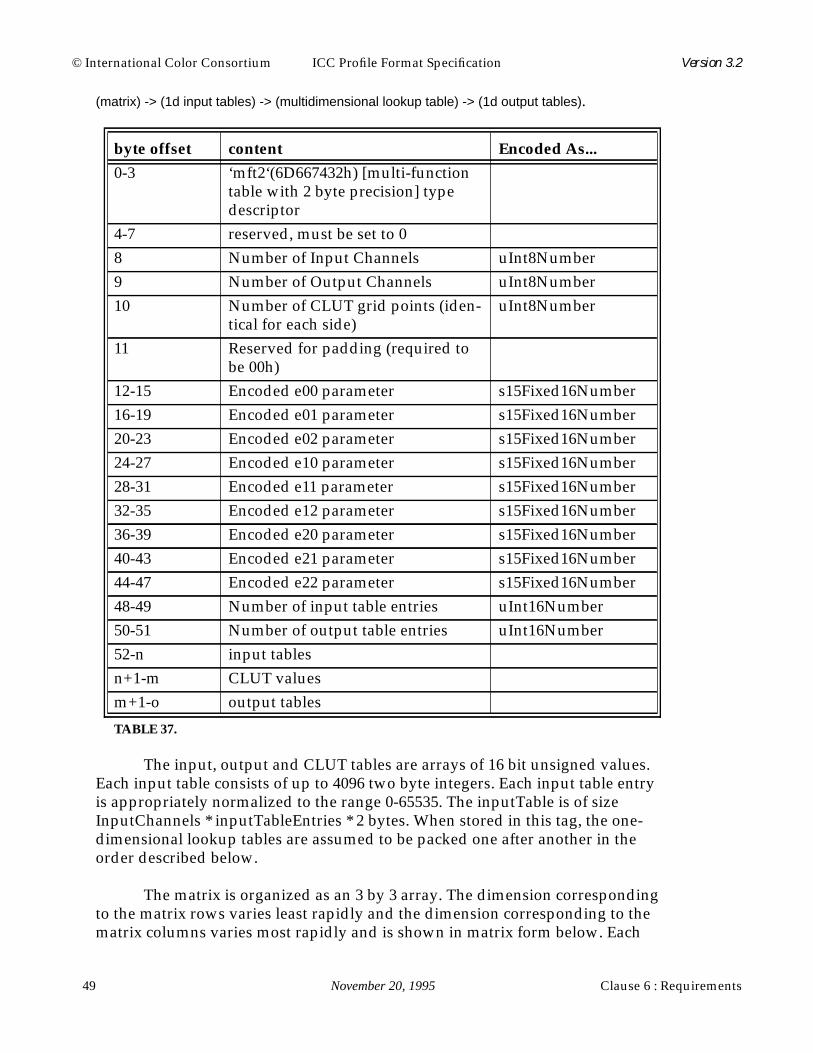
© International Color Consortium ICC Profile Format Specification Version 3.2
49 November 20, 1995 Clause 6 : Requirements
(matrix) -> (1d input tables) -> (multidimensional lookup table) -> (1d output tables).
The input, output and CLUT tables are arrays of 16 bit unsigned values.Each input table consists of up to 4096 two byte integers. Each input table entryis appropriately normalized to the range 0-65535. The inputTable is of sizeInputChannels * inputTableEntries * 2 bytes. When stored in this tag, the one-dimensional lookup tables are assumed to be packed one after another in theorder described below.
The matrix is organized as an 3 by 3 array. The dimension correspondingto the matrix rows varies least rapidly and the dimension corresponding to thematrix columns varies most rapidly and is shown in matrix form below. Each
byte offset content Encoded As...
0-3 ‘mft2‘(6D667432h) [multi-functiontable with 2 byte precision] typedescriptor
4-7 reserved, must be set to 08 Number of Input Channels uInt8Number9 Number of Output Channels uInt8Number10 Number of CLUT grid points (iden-
tical for each side)uInt8Number
11 Reserved for padding (required tobe 00h)
12-15 Encoded e00 parameter s15Fixed16Number16-19 Encoded e01 parameter s15Fixed16Number20-23 Encoded e02 parameter s15Fixed16Number24-27 Encoded e10 parameter s15Fixed16Number28-31 Encoded e11 parameter s15Fixed16Number32-35 Encoded e12 parameter s15Fixed16Number36-39 Encoded e20 parameter s15Fixed16Number40-43 Encoded e21 parameter s15Fixed16Number44-47 Encoded e22 parameter s15Fixed16Number48-49 Number of input table entries uInt16Number50-51 Number of output table entries uInt16Number52-n input tablesn+1-m CLUT valuesm+1-o output tables
TABLE 37.

Clause 6 : Requirements November 20, 1995 50
© International Color Consortium ICC Profile Format Specification Version 3.2
matrix entry is a four byte number with one sign bit, 15 integer bits, and 16fractional bits.
When using the matrix of an output profile, and the input data is XYZ,we have
Each input X, Y or Z is an unsigned 1.15 number and each matrix entry isa signed 15.16 number. Therefore, each multiplication in the matrix multiply is1.15 * s15.16 = s16.31 and the final sum is also s16.31. From this sum we take bits31-16 as the unsigned integer result for X', Y', or Z'. These are then used as theinputs to the input tables of the multidimensional LUT. This normalization isused since the number of fractional bits in the input data must be maintained bythe matrix operation.
The matrix is mandated to be an identity matrix unless the input is in theXYZ color space.
Each CLUT is organized as an n-dimensional array with a given numberof grid points in each dimension, where n is the number of input channels (inputtables) in the transform. The dimension corresponding to the first input channelvaries least rapidly and the dimension corresponding to the last input channelvaries most rapidly. Each grid point value contains m two byte integers, wherem is the number of output functions. The first sequential two byte integer of theentry contains the function value for the first output function, the secondsequential two byte integer of the entry contains the function value for thesecond output function, and so on until all the output functions have beensupplied. Each two byte integer in the CLUT is appropriately normalized to therange of 0 - 65535. The equation for computing the size of the CLUT is:
.
e00 e01 e02
e10 e11 e12
e20 e21 e22
X'
Y'
Z'
XX XY XZ
YX YY YZ
ZX ZY ZZ
X
Y
Z
=
CLUTSize LUTDimensionsInputChannels• OutputChannels 2Bytes•=

© International Color Consortium ICC Profile Format Specification Version 3.2
51 November 20, 1995 Clause 6 : Requirements
Each output table consists of a minimum of two and a maximum of 4096two byte integers. Each output table entry is appropriately normalized to therange 0 - 65535. The outputTable is of size OutputChannels * outputTableEntries* 2 bytes. When stored in this tag, the one-dimensional lookup tables areassumed to be packed one after another in the order described in the followingparagraph.
When using this type, it is necessary to assign each color spacecomponent to an input and output channel. The following table shows theseassignments. The channels are numbered according to the order in which theirtable occurs. Note that additional color spaces can be added simply by definingthe signature, channel assignments, and creating the tables.
6.5.5 lut8Type
This structure converts an input color into an output color using tables of 8 bitprecision. This type contains four processing elements: a 3 by 3 matrix (onlyused when the input color space has three components), a set of onedimensional input lookup tables, a multidimensional lookup table, and a set ofone dimensional output tables. Data is processed using these elements via thefollowing sequence:
Color Space Channel 1 Channel 2 Channel 3 Channel 4
‘XYZ’ X Y Z‘Lab’ L a b‘Luv’ L u v‘YCbr’ Y Cb Cr‘Yxy’ Y x y‘RGB’ R G B‘GRAY’ K‘HSV’ H S V‘HLS’ H L S‘CMYK’ C M Y K‘CMY’ C M Y
TABLE 38.

Clause 6 : Requirements November 20, 1995 52
© International Color Consortium ICC Profile Format Specification Version 3.2
(matrix) -> (1d input tables) -> (multidimensional lookup table) -> (1d output tables).
The input, output and CLUT tables are arrays of 8 bit unsigned values.Each input table consists of 256 one byte integers. Each input table entry isappropriately normalized to the range 0-255. The inputTable is of sizeInputChannels * 256 bytes. When stored in this tag, the one-dimensional lookuptables are assumed to be packed one after another in the order described below.
The matrix is organized as a 3 by 3 array. The dimension correspondingto the matrix rows varies least rapidly and the dimension corresponding to thematrix columns varies most rapidly and is shown in matrix form below.
byte offset content Encoded As...
0-3 ‘mft1‘(6D667431h) [multi-functiontable with 1 byte precision] typedescriptor
4-7 reserved, must be set to 08 Number of Input Channels uInt8Number9 Number of Output Channels uInt8Number10 Number of CLUT grid points (iden-
tical for each side)uInt8Number
11 Reserved for padding (fill with 00h)12-15 Encoded e00 parameter s15Fixed16Number16-19 Encoded e01 parameter s15Fixed16Number20-23 Encoded e02 parameter s15Fixed16Number24-27 Encoded e10 parameter s15Fixed16Number28-31 Encoded e11 parameter s15Fixed16Number32-35 Encoded e12 parameter s15Fixed16Number36-39 Encoded e20 parameter s15Fixed16Number40-43 Encoded e21 parameter s15Fixed16Number44-47 Encoded e22 parameter s15Fixed16Number48-m input tablesm+1-n CLUT valuesn+1-o output tables
TABLE 39.

© International Color Consortium ICC Profile Format Specification Version 3.2
53 November 20, 1995 Clause 6 : Requirements
When using the matrix of an output profile, and the input data is XYZ,we have
Each input X, Y or Z is an unsigned 1.15 number and each matrix entry isa signed 15.16 number. Therefore, each multiplication in the matrix multiply is1.15 * s15.16 = s16.31 and the final sum is also s16.31. From this sum we take bits31-16 as the unsigned integer result for X', Y', or Z'. These are then scaled to therange 0-255 and used as the inputs to the input tables of the multidimensionalLUT. This normalization is used since the number of fractional bits in the inputdata must be maintained by the matrix operation.
The matrix is mandated to be an identity matrix unless the input is in theXYZ color space.
Each CLUT is organized as an n-dimensional array with a variablenumber of grid points in each dimension, where n is the number of inputchannels (input tables) in the transform. The dimension corresponding to thefirst input channel varies least rapidly and the dimension corresponding to thelast input channel varies most rapidly. Each grid point value is an m-byte array.The first sequential byte of the entry contains the function value for the firstoutput function, the second sequential byte of the entry contains the functionvalue for the second output function, and so on until all the output functionshave been supplied. Each byte in the CLUT is appropriately normalized to therange 0 - 255. The equation for computing the size of the CLUT is:
.
Each output table consists of 256 one byte integers. Each output tableentry is appropriately normalized to the range 0 - 255. The outputTable is of size
e00 e01 e02
e10 e11 e12
e20 e21 e22
X'
Y'
Z'
XX XY XZ
YX YY YZ
ZX ZY ZZ
X
Y
Z
=
CLUTSize LUTDimensionsInputChannels• OutputChannels Bytes•=

Clause 6 : Requirements November 20, 1995 54
© International Color Consortium ICC Profile Format Specification Version 3.2
OutputChannels * 256 bytes. When stored in this tag, the one-dimensionallookup tables are assumed to be packed one after another in the order describedin the following paragraph.
When using this type, it is necessary to assign each color spacecomponent to an input and output channel. The following table shows theseassignments. The channels are numbered according to the order in which theirtable occurs. Note that additional color spaces can be added simply by definingthe signature, channel assignments, and creating the tables.
6.5.6 measurementType
The measurementType information refers only to the internal profile data and ismeant to provide profile makers an alternative to the default measurement
Color Space Channel 1 Channel 2 Channel 3 Channel 4
‘XYZ’ X Y Z‘Lab’ L a b‘Luv’ L u v‘Yxy’ Y x y‘YCbr’ Y Cb Cr‘RGB’ R G B‘GRAY’ K‘HSV’ H S V‘HLS’ H L S‘CMYK’ C M Y K‘CMY’ C M Y
TABLE 40.

© International Color Consortium ICC Profile Format Specification Version 3.2
55 November 20, 1995 Clause 6 : Requirements
specifications.
The encoding for the standard observer field is such that:
The encoding for the measurement geometry field is such that:
The encoding for the measurement flare value is shown below and is equivalentto the basic numeric type u16Fixed16Number in Clause 5.2.3.
byteoffset content Encoded As...
0-3 ‘meas‘(6D656173h) type descriptor4-7 reserved, must be set to 08-11 encoded value for standard observer see below12-23 XYZ tristimulus values for measurement
backingXYZNumber
24-27 encoded value for measurement geometry see below28-31 encoded value for measurement flare see below32-35 encoded value for standard illuminant see below
TABLE 41.
Standard Observer Encoded Value
unknown 00000000h1931 2 degree Observer 00000001h1964 10 degree Observer 00000002h
TABLE 42.
Geometry Encoded Value
unknown 00000000h0/45 or 45/0 00000001h0/d or d/0 00000002h
TABLE 43.
Tristimulus Value Encoded Value
0 (0%) 00000000h1.0 (or 100%) 00010000h
TABLE 44.
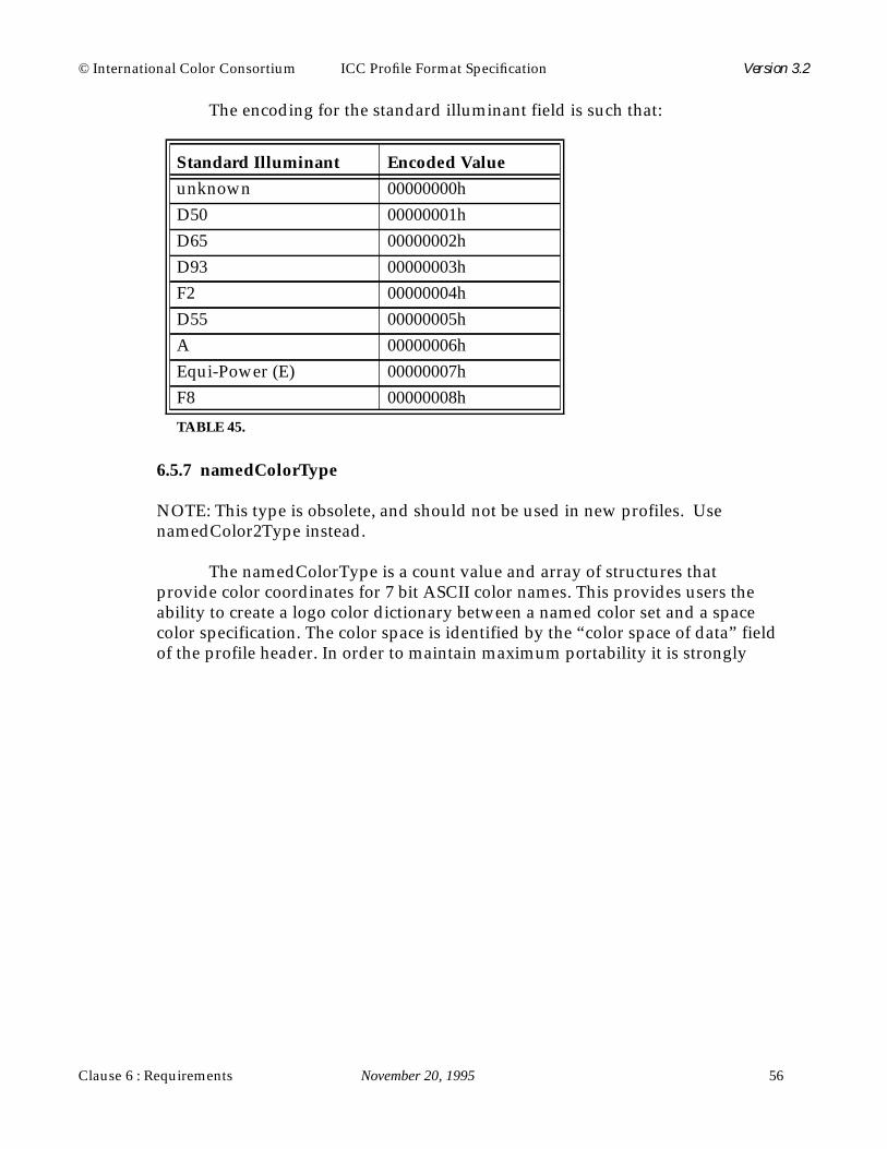
Clause 6 : Requirements November 20, 1995 56
© International Color Consortium ICC Profile Format Specification Version 3.2
The encoding for the standard illuminant field is such that:
6.5.7 namedColorType
NOTE: This type is obsolete, and should not be used in new profiles. UsenamedColor2Type instead.
The namedColorType is a count value and array of structures thatprovide color coordinates for 7 bit ASCII color names. This provides users theability to create a logo color dictionary between a named color set and a spacecolor specification. The color space is identified by the “color space of data” fieldof the profile header. In order to maintain maximum portability it is strongly
Standard Illuminant Encoded Value
unknown 00000000hD50 00000001hD65 00000002hD93 00000003hF2 00000004hD55 00000005hA 00000006hEqui-Power (E) 00000007hF8 00000008h
TABLE 45.

© International Color Consortium ICC Profile Format Specification Version 3.2
57 November 20, 1995 Clause 6 : Requirements
recommended that special characters of the 7 bit ASCII set not be used.
6.5.8 namedColor2Type
The namedColor2Type is a count value and array of structures that providecolor coordinates for 7 bit ASCII color names. For each named color, a PCS andoptional device representation of the color are given. Both representations are16 bit values. The device representation corresponds to the header's "color spaceof data" field. This representation should be consistent with the "number ofdevice components" field in the namedColor2Type. If this field is 0, devicecoordinates are not provided. The PCS representation corresponds to theheader's PCS field. The PCS representation is always provided. Color namesare fixed-length, 32 byte fields including null termination. In order to maintainmaximum portability, it is strongly recommended that special characters of the 7bit ASCII set not be used.
byte offset content Encoded As...
0-3 ‘ncol‘(6E636F6Ch) type descriptor4-7 reserved, must be set to 08-11 vendor specific flag (lower 16 bits
reserved for Consortium use)12-15 count of named colors uInt32Number15-t prefix for each color name (maximum
of 32 bytes) 7 bit ASCII, 0 terminatedt+1-u suffix for each color name (maximum
of 32 bytes) 7 bit ASCII, 0 terminatedu+1-v first color root name (maximum of 32
bytes) 7 bit ASCII, 0 terminatedv+1-w first name's color coordinates. Color
space of dataw+1-x second color root name (maximum of
32 bytes) 7 bit ASCII, 0 terminatedx+1-y second name's color coordinates. Color
space of datay+1-z the remaining count-2 name structures
as described in the first two namestructures (assuming count > 2)
TABLE 46.

Clause 6 : Requirements November 20, 1995 58
© International Color Consortium ICC Profile Format Specification Version 3.2
The namedColorType should no longer be used.
6.5.9 profileSequenceDescType
This type is an array of structures, each of which contains information from the
byte offset content Encoded As...
0-3 ‘ncol‘(6E636F6Ch) type descriptor4-7 reserved, must be set to 08-11 vendor specific flag (lower 16 bits
reserved for Consortium use)12-15 count of named colors uInt32Number15-19 number of device coordinates for each
named coloruInt32Number
20-51 prefix for each color name (32 byte fieldincluding null termination) 7 bit ASCII
52-83 suffix for each color name (32 byte fieldincluding null termination) 7 bit ASCII
84-115 first color root name (32 byte fieldincluding null termination) 7 bit ASCII
116-x first named color's PCS coordinates.Each coordinate is a uInt16Number.The encoding is the same as the encod-ings for the PCS color spaces asdescribed in Annex A : 'Color Spaces'.Only 16 bit L*a*b* and XYZ areallowed. The number of coordinates isconsistent with the header's PCS.
x+1-y first named color's device coordinates.Each coordinate is a uInt16Numberwhere 0000h represents the minimumvalue for the device coordinate andFFFFh represents the maximum valuefor the device coordinate. The numberof coordinates is given by the "numberof device coordinates" field. If the"number of device coordinates" field is0, this field is not given.
y+1-z if count > 1 the remaining count-1 col-ors are described in a manner consis-tent with the first named color.
TABLE 47.

© International Color Consortium ICC Profile Format Specification Version 3.2
59 November 20, 1995 Clause 6 : Requirements
header fields and tags from the original profiles which were combined to createthe final profile. The order of the structures is the order in which the profileswere combined and includes a structure for the final profile. This provides adescription of the profile sequence from source to destination, typically usedwith the devicelink profile.
Each profile description structure has the format:
If the deviceMfgDescTag and/or deviceModelDescTag is not present in acomponent profile, then a “placeholder” tag should be inserted. This tag shouldhave a 1 in the ASCII count field and a terminating null in the ASCII invariantprofile description and zeros in the UniCode and ScriptCode count and codefields.
Also note that the entire tag, including the tag type, should be stored.
If the technologyTag is not present, bytes 16-19 should be filled in aszeros.
byteoffset content
0-3 ‘pseq’(70736571h) type descriptor4-7 reserved, must be set to 08-11 count value specifying number of description structures in the
array12-m ‘count’ profile description structures
TABLE 48.
byteoffset content
0-3 Device manufacturer signature (from corresponding profile’sheader)
4-7 Device model signature (from corresponding profile’s header)8-15 Device attributes (from corresponding profile’s header)16-19 Device technology information such as CRT, Dye Sublimation, etc.
(corresponding profile’s technology signature)20-m displayable description of device manufacturer (corresponding
profile’s deviceMfgDescTag)m+1- n displayable description of device model (corresponding profile’s
deviceModelDescTag)
TABLE 49.

Clause 6 : Requirements November 20, 1995 60
© International Color Consortium ICC Profile Format Specification Version 3.2
6.5.10 s15Fixed16ArrayType
This type represents an array of generic 4 byte/32 bit fixed point quantity. Thenumber of values is determined from the size of the tag.
6.5.11 screeningType
The screeningType describes various screening parameters including screenfrequency, screening angle, and spot shape.
Screening flag encoding is such that:
byteoffset content
0-3 ‘sf32‘(73663332h) type descriptor4-7 reserved, must be set to 08-n an array of s15Fixed16Number values
TABLE 50.
byteoffset content Encoded As...
0-3 ‘scrn‘(7363726Eh) type descriptor4-7 reserved, must be set to 08-11 screening flag see below12-15 number of channels16-19 channel #1 frequency s15Fixed16Number20-23 channel #1 screen angle (degrees) s15Fixed16Number24-27 channel #1 spot shape see below28-n frequency, screen angle (degrees) and spot
shape for additional channelssee below
TABLE 51.
Attribute bit position
Use Printer Default Screens (true is 1) 0Frequency units in Lines/Inch (value 1) orLines/cm (value 0)
1
TABLE 52.

© International Color Consortium ICC Profile Format Specification Version 3.2
61 November 20, 1995 Clause 6 : Requirements
Spot function encoding is such that:
6.5.12 signatureType
The signatureType contains a four byte sequence used for signatures. Typicallythis type is used for tags that need to be registered and can be displayed onmany development systems as a sequence of four characters. Sequences of lessthan four characters are padded at the end with spaces, 20h.
6.5.13 textDescriptionType
The textDescriptionType is a complex structure that contains three types of textdescription structures: 7 bit ASCII, Unicode and ScriptCode. Since no singlestandard method for specifying localizable character sets exists across the majorplatform vendors, including all three provides access for the major operatingsystems. The 7 bit ASCII description is to be an invariant, nonlocalizable namefor consistent reference. It is preferred that both the Unicode and ScriptCodestructures be properly localized.
The localized Macintosh profile description contains 67 bytes of data, ofwhich at most ‘count’ bytes contain a ScriptCode string, including a nullterminator. The ‘count’ cannot be greater than 67.
Spot Function Value Encoded Value
unknown 0printer default 1round 2diamond 3ellipse 4line 5square 6cross 7
TABLE 53.
byteoffset content
0-3 ‘sig ‘(73696720h) type descriptor4-7 reserved, must be set to 08-11 four byte signature
TABLE 54.

Clause 6 : Requirements November 20, 1995 62
© International Color Consortium ICC Profile Format Specification Version 3.2
The count field for each types are defined as follows:
ASCII: The count is the length of the string in bytes including the nullterminator.
Unicode: The count is the number of characters including a Unicode nullwhere a character is always two bytes.
ScriptCode: The count is the length of the string in bytes including theterminating.
If both Unicode and ScriptCode structures cannot be localized then thefollowing guidelines should be used:
If Unicode is not native on the platform, then the Unicode language codeand Unicode count should be filled in as 0, with no data placed in the Unicodelocalizable profile description area.
If Scriptcode is not native on the platform, then the ScriptCode code andScriptCode count should be filled in as 0. The 67 byte localizable Macintoshprofile description should be filled with 0’s.
An example of a textDescriptionType which has neither Unicode nor
byte offset content
0-3 ‘desc‘(64657363h) type descriptor4-7 reserved, must be set to 08-11 7 bit ASCII invariant Profile description count, including
terminating null (description length)12-n-1 7 bit ASCII invariant Profile descriptionn-n+3 Unicode language coden+4-n+7 Unicode localizable Profile description count (description
length)n+8-m-1 Unicode localizable Profile descriptionm-m+1 ScriptCode codem+2 Localizable Macintosh Profile description count (descrip-
tion length)m+3-m+69 Localizable Macintosh Profile description
TABLE 55.

© International Color Consortium ICC Profile Format Specification Version 3.2
63 November 20, 1995 Clause 6 : Requirements
ScriptCode is:.
6.5.14 textType
The textType is a simple text structure that contains a 7 bit ASCII text string. Thelength of the string can easily be obtained from the element size portion of thetag itself. This string must be terminated with a 00h byte.
6.5.15 u16Fixed16ArrayType
This type represents an array of generic 4 byte/32 bit quantity. The number of
byte offset content
0-3 ‘desc‘(64657363h)4-7 reserved, must be set to 08-11 uInt32Number = 15, ASCII count12-26 ASCII string “An ICC Profile” with a NULL byte at the end27-30 uInt32Number = 0 (Unicode code)31-34 uInt32Number = 0 (Unicode count)35-36 uInt16Number = 0 (ScriptCode code)37 uIInt8Number = 0 (ScriptCode count)38-104 uIInt8Number[67] filled with 0’s
TABLE 56.
byteoffset content
0-3 ‘text‘(74657874h) type descriptor4-7 reserved, must be set to 08-n a string of count ASCII characters (where count is derived from the
element size portion of the tag itself)

Clause 6 : Requirements November 20, 1995 64
© International Color Consortium ICC Profile Format Specification Version 3.2
values is determined from the size of the tag.
6.5.16 ucrbgType
This type contains curves representing the under color removal and blackgeneration and a text string which is a general description of the method usedfor the ucr/bg.
6.5.17 uInt16ArrayType
This type represents an array of generic 2 byte/16 bit quantity. The number of
byteoffset content
0-3 ‘uf32‘(75663332h) type descriptor4-7 reserved, must be set to 08-n an array of u16Fixed16Number values
TABLE 57.
byteoffset content
0-3 ‘bfd ’(62666420h) type descriptor4-7 reserved, must be set to 08-11 count value specifying number of entries in the ucr curve12-m actual ucr curve values starting with the zeroth entry and ending
with the entry count-1. Each value is a uInt16Number. If the countis 1, the value is a percent.
m+1 - n count value specifying number of entries in the bg curven+1 - o actual bg curve values starting with the zeroth entry and ending
with the entry count-1. Each value is a uInt16Number. If the countis 1, the value is a percent.
o+1 - p a string of ASCII characters, with a null terminator.
TABLE 58.

© International Color Consortium ICC Profile Format Specification Version 3.2
65 November 20, 1995 Clause 6 : Requirements
values is determined from the size of the tag.
6.5.18 uInt32ArrayType
This type represents an array of generic 4 byte/32 bit quantity. The number ofvalues is determined from the size of the tag.
6.5.19 uInt64ArrayType
This type represents an array of generic 8 byte/64 bit quantity. The number ofvalues is determined from the size of the tag.
6.5.20 uInt8ArrayType
This type represents an array of generic 1 byte/8 bit quantity. The number of
byteoffset content
0-3 ‘ui16‘(75693136h) type descriptor4-7 reserved, must be set to 08-n an array of unsigned 16 bit integers
TABLE 59.
byteoffset content
0-3 ‘ui32‘(75693332h) type descriptor4-7 reserved, must be set to 08-n an array of unsigned 32 bit integers
TABLE 60.
byteoffset content
0-3 ‘ui64‘(75693634h) type descriptor4-7 reserved, must be set to 08-n an array of unsigned 64 bit integers
TABLE 61.

Clause 6 : Requirements November 20, 1995 66
© International Color Consortium ICC Profile Format Specification Version 3.2
values is determined from the size of the tag.
6.5.21 viewingConditionsType
This type represents a set of viewing condition parameters including: absoluteilluminant white point tristimulus values and absolute surround tristimulusvalues.
6.5.22 XYZType
The XYZType contains an array of three encoded values for the XYZ tristimulusvalues. The number of sets of values is determined from the size of the tag. Thebyte stream is given below. Tristimulus values must be non-negative, the signedencoding allows for implementation optimizations by minimizing the number offixed formats.
byteoffset content
0-3 ‘ui08‘(75693038h) type descriptor4-7 reserved, must be set to 08-n an array of unsigned 8 bit integers
TABLE 62.
byteoffset content Encoded As...
0-3 ‘view‘(76696577h) type descriptor4-7 reserved, must be set to 08-19 absolute XYZ value for illuminant in cd/m2 XYZNumber20-31 absolute XYZ value for surround in cd/m2 XYZNumber32-35 illuminant type as described in
measurement-Type
TABLE 63.
byteoffset content Encoded As...
0-3 ‘XYZ ‘(58595A20h) type descriptor4-7 reserved, must be set to 08-n an array of XYZ numbers XYZNumber
TABLE 64.

© International Color Consortium ICC Profile Format Specification Version 3.2
67 November 20, 1995 Annex Annex A : Color Spaces
Annex A : Color Spaces
The International Color Profile Format supports a variety of both device-dependent and device-independent color spaces divided into three basicfamilies: 1) CIEXYZ based, 2) RGB based, and 3) CMY based.
The CIE color spaces are defined in CIE publication 15.2 on Colorimetry.A subset of the CIEXYZ based spaces are also defined as exchange spaces. Thedevice dependent spaces below are only representative and other devicedependent color spaces may be used without needing to update the profileformat specification or the software that uses it.
A.1 Profile Connection Spaces
A key component of these profiles is a well-defined profile connectionspace. This space is the interface which provides an unambiguous connectionbetween the input and output profiles as illustrated in the diagram below. Theprofile connection space is based on the CIE 1931 standard observer. Thisexperimentally derived standard observer provides a very good representationof the human visual system color matching capabilities. Unlike devicedependent color spaces, if two colors have the same CIE colorimetry they willmatch if viewed under the same conditions. Because the imagery is typicallyproduced for a wide variety of viewing environments, it is necessary to gobeyond simple application of the CIE system.
Base Space Description Derivative Space
CIEXYZ base CIE device-independent color space CIELAB
GRAY monochrome device-dependent color space
RGB base additive device-dependent color space HLS, HSV
CMYK base subtractive device-dependent color space CMYTABLE 65.

Annex Annex A : Color Spaces November 20, 1995 68
© International Color Consortium ICC Profile Format Specification Version 3.2
FIGURE 3.
The profile connection space is defined as the CIE colorimetry which willproduce the desired color appearance if rendered on a reference imaging mediaand viewed in a reference viewing environment. This reference corresponds toan ideal reflection print viewed in an ANSI standard viewing booth.
The default measurement parameters for the profile connection spaceand all other color spaces defined in this specification are based on the ANSICGATS.5-1993 standard, “Graphic technology - Spectral measurement andcolorimetric computation for graphic arts images.” Essentially this defines astandard illuminant of D50, the 1931 CIE standard observer, and 0/45 or 45/0reflectance measurement geometry. The reference viewing condition is ANSIPH2.30-1989, which is a D50 graphic arts viewing environment.
One of the first steps in profile building involves measuring thecolorimetry of a set of colors from some imaging media or display. If theimaging media or viewing environment differ from the reference, it will benecessary to adapt the measured colorimetry to that appropriate for the profileconnection space. These adaptations account for such differences as white pointchromaticity and luminance relative to an ideal reflector, maximum density,viewing surround, viewing illuminant, and flare. Currently, it is theresponsibility of the profile builder to do this adaptation.
However, the possibility of allowing a variable illuminant in the PCSis under active consideration by the International Color Consortium. For thisreason, a PCS illuminant field is in the profile header, but must be set to the CIEIlluminant D50 [X=0.9642, Y=1.0000, Z=0.8249].
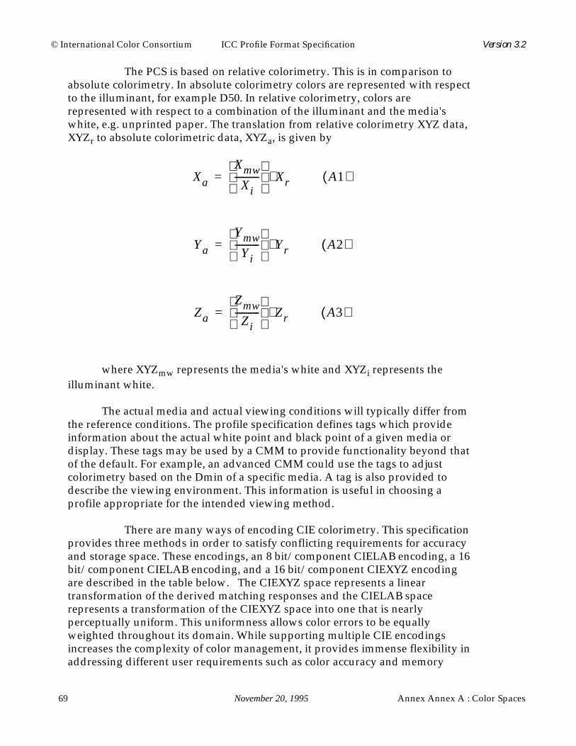
© International Color Consortium ICC Profile Format Specification Version 3.2
69 November 20, 1995 Annex Annex A : Color Spaces
The PCS is based on relative colorimetry. This is in comparison toabsolute colorimetry. In absolute colorimetry colors are represented with respectto the illuminant, for example D50. In relative colorimetry, colors arerepresented with respect to a combination of the illuminant and the media'swhite, e.g. unprinted paper. The translation from relative colorimetry XYZ data,XYZr to absolute colorimetric data, XYZa, is given by
where XYZmw represents the media's white and XYZi represents theilluminant white.
The actual media and actual viewing conditions will typically differ fromthe reference conditions. The profile specification defines tags which provideinformation about the actual white point and black point of a given media ordisplay. These tags may be used by a CMM to provide functionality beyond thatof the default. For example, an advanced CMM could use the tags to adjustcolorimetry based on the Dmin of a specific media. A tag is also provided todescribe the viewing environment. This information is useful in choosing aprofile appropriate for the intended viewing method.
There are many ways of encoding CIE colorimetry. This specificationprovides three methods in order to satisfy conflicting requirements for accuracyand storage space. These encodings, an 8 bit/component CIELAB encoding, a 16bit/component CIELAB encoding, and a 16 bit/component CIEXYZ encodingare described in the table below. The CIEXYZ space represents a lineartransformation of the derived matching responses and the CIELAB spacerepresents a transformation of the CIEXYZ space into one that is nearlyperceptually uniform. This uniformness allows color errors to be equallyweighted throughout its domain. While supporting multiple CIE encodingsincreases the complexity of color management, it provides immense flexibility inaddressing different user requirements such as color accuracy and memory
Xa
Xmw
Xi-----------
Xr⋅= A1( )
Ya
Ymw
Yi-----------
Yr⋅= A2( )
Za
Zmw
Zi-----------
Zr⋅= A3( )

Annex Annex A : Color Spaces November 20, 1995 70
© International Color Consortium ICC Profile Format Specification Version 3.2
footprint.
The encoding is such that
An important point to be made is that the PCS is not necessarily intendedfor the storage of images. A separate series of “interchange color spaces” may bedefined in a future version of this specification for this purpose. The designchoices made for these spaces (colorimetric encoding, reference media, viewingconditions, etc.) might be different than that of the PCS.
Interchange Space Component Actual Range Encoded
CIE XYZ X 0 -> 1.99997 0000h -> FFFFh
CIE XYZ Y 0 -> 1.99997 0000h -> FFFFh
CIE XYZ Z 0 -> 1.99997 0000h -> FFFFh
CIELAB (16 bit) L* 0 -> 100.0 0000h -> FF00h
CIELAB (16 bit) a* -128.0 -> + 127.996 0000h -> FFFFh
CIELAB (16 bit) b* -128.0 -> + 127.996 0000h -> FFFFh
CIELAB (8 bit) L* 0 -> 100.0 00h -> FFh
CIELAB (8 bit) a* -128.0 -> + 127.0 00h -> FFh
CIELAB (8 bit) b* -128.0 -> + 127.0 00h -> FFhTABLE 66.

© International Color Consortium ICC Profile Format Specification Version 3.2
71 November 20, 1995 Annex Annex B : Embedding Profiles
Annex B : Embedding Profiles
This annex details the requirements and options for embedding deviceprofiles within PICT, EPS and TIFF documents. All profiles except abstractprofiles can be embedded. The complete profile must be embedded with all tagsintact and unchanged.
Embedding devicelink profiles renders the color data devicedependent and significantly reduces portability. This may be useful in somesituations, but may also cause problems with accurate color reproduction.
B.1 Embedding ICC Profiles in PICT Files
Apple has defined a new QuickDraw picture comment type forembedded ICC profiles. The picture comment value of 224 is followed by a 4-byte selector that describes the type of data in the comment. Using a selectorallows the flexibility to embed more CMM related information in the future. Thefollowing selectors are currently defined:
Because the dataSize parameter of the PicComment procedure is a signed16-bit value, the maximum amount of profile data that can be embedded in asingle picture comment is 32763 bytes (32767 - 4 bytes for the selector). You canembed a larger profile by using multiple picture comments of selector type 1.The profile data must be embedded in consecutive order, and the last piece ofprofile data must be followed by a picture comment of selector type 2.
All embedded ICC profiles, including those that fit within a single picturecomment, must be followed by the end-of-profile picture comment (selector 2),as shown in the following examples.
Example 1: Embedding a 20K profile.
PicComment kind = 224, dataSize = 20K + 4, selector = 0, profile data = 20K
PicComment kind = 224, dataSize = 4, selector = 2
Example 2: Embedding a 50K profile.
PicComment kind = 224, dataSize = 32K, selector = 0, profile data = 32K - 4
TABLE 67.
Selector Description
0 Beginning of an ICC profile. Profile data to follow.1 Continuation of ICC profile data. Profile data to follow.2 End of ICC profile data. No profile data follows.
Annex Annex B : Embedding Profiles November 20, 1995 72
© International Color Consortium ICC Profile Format Specification Version 3.2
PicComment kind = 224, dataSize = 18K + 8, selector = 1, profile data = 18K + 4
PicComment kind = 224, dataSize = 4, selector = 2
In ColorSync 1.0, picture comment types CMBeginProfile (220) andCMEndProfile (221) are used to begin and end a picture comment. TheCMBeginProfile comment is not supported for ICC profiles; however, theCMEndProfile comment can be used to end the current profile and begin usingthe System Profile for both ColorSync 1.0 and 2.0.
The CMEnableMatching (222) and CMDisableMatching (223) picturecomments are used to begin and end color matching in both ColorSync 1.0 and2.0
See “Advanced Color Imaging on the Mac OS”, Apple Computer 1995,for more information about picture comments.
B.2 Embedding ICC Profiles in EPS Files
There are two places within EPS files that embedding International ColorConsortium (ICC) profiles are appropriate. 1) Associated with a screen preview.2) Associated with the page description. Embedding ICC profiles within a screenpreview is necessary so that applications using this screen preview to display arepresentation of the EPS page description can do so with accurate colors.Embedding ICC profiles within a page description is necessary so thatsophisticated applications, such as OPI server software, can perform colorconversions along with image replacement. For general information concerningPostScript's Document Structuring Conventions (DSC), the EPS file format, orspecific PostScript operators, see the PostScript Language Reference Manual,second edition.
1) There are a variety of different methods of storing a screen previewwithin an EPS file depending on the intended environment. For cross platformapplications with embedded ICC profiles, TIFF screen previews arerecommended. The TIFF format has been extended to support the embedding ofICC profiles. ICC profiles can also be embedded in a platform specific manner.For example on the Macintosh, Apple has defined a method for embedding ICCprofiles in PICT files, see clause B.1 Embedding ICC Profiles in PICT Files.
Note that a given page description may use multiple distinct color spaces.In such cases, color conversions must be performed to a single color space toassociate with the screen preview.
2) ICC profiles can also be embedded in the page description portion ofan EPS file using the%%BeginICCProfile / %%EndICCProfile comments. Thisconvention is defined as follows.

© International Color Consortium ICC Profile Format Specification Version 3.2
73 November 20, 1995 Annex Annex B : Embedding Profiles
%%BeginICCProfile: <profileid> <numberof> [<type> [<bytesorlines>]]
<profileid> ::= <text> (Profile ID)
<numberof> ::= <int> (Lines or physical bytes)
<type> ::= Hex | ASCII (Type of data)
<bytesorlines> ::= Bytes | Lines (Read in bytes or lines)
%%EndICCProfile (no keywords)
These comments are designed to provide information about embeddedICC profiles. If the type argument is missing, ASCII data is assumed. ASCIIrefers to an ASCII base-85 representation of the data. If the bytesorlinesargument is missing, <numberof > shall be considered to indicate bytes of data.If <numberof > = -1, the number of bytes of data are unknown. In this case, toskip over the profile one must read data until the encountering the%%EndICCProfile comment.
<profileID > provides the profile's ID in order to synchronize it withPostScript's setcolorspace and findcolorrendering operators and associatedoperands (see below). Note that <numberof > indicates the bytes of physicaldata, which vary from the bytes of virtual data in some cases. With hex, eachbyte of virtual data is represented by two ASCII characters (two bytes ofphysical data). Although the PostScript interpreter ignores white space andpercent signs in hex and ASCII data, these count toward the byte count.
Each line of profile data shall begin with a single percent sign followed bya space (%). This makes the entire profile section a PostScript language commentso the file can be sent directly to a printer without modification. The spaceavoids confusion with the open extension mechanism associated with DSCcomments.
ICC profiles can be embedded within EPS files to allow sophisticatedapplications, such as OPI server software, to extract the profiles, and to performcolor processing based on these profiles. In such situations it is desirable tolocate the page description's color space and rendering intent, since this colorspace and rendering intent may need to be modified based on any colorprocessing. The %%BeginSetColorSpace / %%EndSetColorSpace and%%BeginRenderingIntent / %%EndRenderingIntent comments are usedto delimit the color space and rendering intent respectively.
%%BeginSetColorSpace <profileid>
<profileid> ::= <text> (ICC Profile ID)
%%EndSetColorSpace (no keywords)
Annex Annex B : Embedding Profiles November 20, 1995 74
© International Color Consortium ICC Profile Format Specification Version 3.2
<profileid > provides the ICC profile's ID corresponding to this colorspace. The ICC profile with this profile must have occured in the PostScript jobusing the %%BeginICCProfile / %%EndICCProfile comment convention priorto this particular %%BeginSetColorSpace comment.
An example usage is shown here for CIE 1931 (XYZ)-space with D65white point that refers to the ICC profile with <profileid > = XYZProfile.
%%BeginSetColorSpace XYZProfile
[/CIEBasedABC <<
/WhitePoint [0.9505 1 1.0890]
/RangeABC [0 0.9505 0 1 0 1.0890]
/RangeLMN [0 0.9505 0 1 0 1.0890]
>>] setcolorspace
%%EndSetColorSpace
Note that the setcolorspace command is included within the comments.The PostScript enclosed in these comments shall not perform any otheroperations other than setting the color space and shall have no side effects.
%%BeginRenderingIntent <profileid>
<profileid> ::= <text> (ICC Profile ID)
%%EndRenderingIntent
<profileid > provides the ICC profile's ID corresponding to thisrendering intent. The ICC profile with this profile must have occured in thePostScript job using the %%BeginICCProfile / %%EndICCProfile commentconvention prior to invocation of this particular %%BeginRenderingIntentcomment.
An example usage is shown here for the the Perceptual rendering intentthat refers to the ICC profile with <profileid > = RGBProfile.
%%BeginRenderingIntent RGBProfile
/Perceptual findcolorrendering pop
/ColorRendering findresource setcolorrendering
%%EndRenderingIntent
Note that the setcolorrendering command is included within the

© International Color Consortium ICC Profile Format Specification Version 3.2
75 November 20, 1995 Annex Annex B : Embedding Profiles
comments. The PostScript enclosed in these comments shall not perform anyother operations other than setting the rendering intent and shall have no sideeffects.
B.3 Embedding ICC Profiles in TIFF Files
The discussion below assumes some familiarity with TIFF internalstructure. It is beyond the scope of this document to detail the TIFF format, andreaders are referred to the “TIFF(tm) Revision 6.0" specification, which isavailable from the Adobe Corporation.
The International Color Consortium (ICC) has been assigned a privateTIFF tag for purposes of embedding ICC device profiles within TIFF image files.This is not a required TIFF tag, and Baseline TIFF readers are not currentlyrequired to read it. It is, however, strongly recommended that this tag behonored.
An ICC device profile is embedded, in its entirety, as a single TIFF field orImage File Directory (IFD) entry in the IFD containing the corresponding imagedata. An IFD should contain no more than one embedded profile. A TIFF filemay contain more than one image, and so, more than one IFD. Each IFD mayhave its own embedded profile. Note, however, that Baseline TIFF readers arenot required to read any IFDs beyond the first one.
The structure of the ICC Profile IFD Entry is as follows.
Like all IFD entry values, the embedded profile must begin on a wordboundary, so the Value Offset will always be an even number.
A TIFF reader should have no knowledge of the internal structure of anembedded ICC profile and should extract the profile intact.
TABLE 68.
ByteOffset
0-1 The TIFFTag that identifies the field = 34675(8773.H)2-3 The field Type = 7 = UNDEFINED (treated as 8-bit bytes).4-7 The Count of values = the size of the embedded ICC profile in
bytes.8-11 The Value Offset = the file offset, in bytes, to the beginning of the
ICC profile.

Annex C : C Header File Example November 20, 1995 76
© International Color Consortium ICC Profile Format Specification Version 3.2
Annex C : C Header File Example
This annex provides a cross-platform conditionally compilable header file forthe InterColor Profile Format.
Contact the ICC technical secretary (Clause 0.7 : Registration Authority)for the latest version of this C header file.
/* Header file guard bands */
#ifndef ICC_H
#define ICC_H
/*****************************************************************
Copyright (c) 1994 SunSoft, Inc.
Rights Reserved
Permission is hereby granted, free of charge, to any person
obtaining a copy of this software and associated documentation
files (the “Software”), to deal in the Software without restrict-
ion, including without limitation the rights to use, copy, modify,
merge, publish distribute, sublicense, and/or sell copies of the
Software, and to permit persons to whom the Software is furnished
to do so, subject to the following conditions:
The above copyright notice and this permission notice shall be
included in all copies or substantial portions of the Software.
THE SOFTWARE IS PROVIDED “AS IS”, WITHOUT WARRANTY OF ANY KIND,
EXPRESS OR IMPLIED, INCLUDING BUT NOT LIMITED TO THE WARRANTIES
OF MERCHANTABILITY, FITNESS FOR A PARTICULAR PURPOSE AND NON-
INFRINGEMENT. IN NO EVENT SHALL SUNSOFT, INC. OR ITS PARENT
COMPANY BE LIABLE FOR ANY CLAIM, DAMAGES OR OTHER LIABILITY,
WHETHER IN AN ACTION OF CONTRACT, TORT OR OTHERWISE, ARISING
FROM, OUT OF OR IN CONNECTION WITH THE SOFTWARE OR THE USE OR
OTHER DEALINGS IN THE SOFTWARE.
Except as contained in this notice, the name of SunSoft, Inc.
shall not be used in advertising or otherwise to promote the
sale, use or other dealings in this Software without written
authorization from SunSoft Inc.
******************************************************************/
© International Color Consortium ICC Profile Format Specification Version 3.2
77 November 20, 1995 Annex C : C Header File Example
/*
* This version of the header file corresponds to the profile
* specification version 3.0.1, and includes support for the
* Named Color profile type approved August 1995.
*
* All header file entries are pre-fixed with “ic” to help
* avoid name space collisions. Signatures are pre-fixed with
* icSig.
*
* The structures defined in this header file were created to
* represent a description of an ICC profile on disk. Rather
* than use pointers a technique is used where a single byte array
* was placed at the end of each structure. This allows us in “C”
* to extend the structure by allocating more data than is needed
* to account for variable length structures.
*
* This also ensures that data following is allocated
* contiguously and makes it easier to write and read data from
* the file.
*
* For example to allocate space for a 256 count length UCR
* and BG array, and fill the allocated data. Note strlen + 1
* to remember NULL terminator.
*
icUcrBgCurve *ucrCurve, *bgCurve;
int ucr_nbytes, bg_nbytes, string_bytes;
icUcrBg *ucrBgWrite;
char ucr_string[100], *ucr_char;
strcpy(ucr_string, “Example ucrBG curves”);
ucr_nbytes = sizeof(icUInt32Number) +
(UCR_CURVE_SIZE * sizeof(icUInt16Number));
bg_nbytes = sizeof(icUInt32Number) +
(BG_CURVE_SIZE * sizeof(icUInt16Number));
string_bytes = strlen(ucr_string) + 1;
ucrBgWrite = (icUcrBg *)malloc(
(ucr_nbytes + bg_nbytes + string_bytes));
ucrCurve = (icUcrBgCurve *)ucrBgWrite->data;
ucrCurve->count = UCR_CURVE_SIZE;
for (i=0; i<ucrCurve->count; i++)
ucrCurve->curve[i] = (icUInt16Number)i;

Annex C : C Header File Example November 20, 1995 78
© International Color Consortium ICC Profile Format Specification Version 3.2
bgCurve = (icUcrBgCurve *)((char *)ucrCurve + ucr_nbytes);
bgCurve->count = BG_CURVE_SIZE;
for (i=0; i<bgCurve->count; i++)
bgCurve->curve[i] = 255 - (icUInt16Number)i;
ucr_char = (char *)((char *)bgCurve + bg_nbytes);
memcpy(ucr_char, ucr_string, string_bytes);
*
*/
/*
* Many of the structures contain variable length arrays. This
* is represented by the use of the convention.
*
* type data[icAny];
*/
/*------------------------------------------------------------------------*/
/*
* Defines used in the specification
*/
#define icMagicNumber 0x61637370L/* ‘acsp’ */
#define icVersionNumber 0x02000000L/* 2.0, BCD */
/* Screening Encodings */
#define icPrtrDefaultScreensFalse0x00000000L/* Bit position 0 */
#define icPrtrDefaultScreensTrue 0x00000001L/* Bit position 0 */
#define icLinesPerInch 0x00000002L/* Bit position 1 */
#define icLinesPerCm 0x00000000L/* Bit position 1 */
/*
* Device attributes, currently defined values correspond
* to the low 4 bytes of the 8 byte attribute quantity, see
* the header for their location.
*/
#define icReflective 0x00000000L/* Bit position 0 */
#define icTransparency 0x00000001L/* Bit position 0 */
#define icGlossy 0x00000000L/* Bit position 1 */
#define icMatte 0x00000002L/* Bit position 1 */
/*
* Profile header flags, the low 16 bits are reserved for consortium

© International Color Consortium ICC Profile Format Specification Version 3.2
79 November 20, 1995 Annex C : C Header File Example
* use.
*/
#define icEmbeddedProfileFalse 0x00000000L/* Bit position 0 */
#define icEmbeddedProfileTrue 0x00000001L/* Bit position 0 */
#define icUseAnywhere 0x00000000L/* Bit position 1 */
#define icUseWithEmbeddedDataOnly 0x00000002L/* Bit position 1 */
/* Ascii or Binary data */
#define icAsciiData 0x00000000L/* Used in dataType */
#define icBinaryData 0x00000001L
/*
* Define used to indicate that this is a variable length array
*/
#define icAny 1
/*------------------------------------------------------------------------*/
/*
* Use this area to translate platform definitions of long
* etc into icXXX form. The rest of the header uses the icXXX
* typedefs. Signatures are 4 byte quantities.
*/
#ifdef __sgi
#include “sgidefs.h”
typedef __int32_t icSignature;
/*
* Number definitions
*/
/* Unsigned integer numbers */
typedef unsigned char icUInt8Number;
typedef unsigned short icUInt16Number;
typedef __uint32_t icUInt32Number;
typedef __uint32_t icUInt64Number[2];
/* Signed numbers */
typedef char icInt8Number;
typedef short icInt16Number;
typedef __int32_t icInt32Number;
typedef __int32_t icInt64Number[2];

Annex C : C Header File Example November 20, 1995 80
© International Color Consortium ICC Profile Format Specification Version 3.2
/* Fixed numbers */
typedef __int32_t icS15Fixed16Number;
typedef __uint32_ticU16Fixed16Number;
#endif /* Silicon Graphics */
#if defined(sun) || defined(__sun)/* 32-bit Solaris, SunOS */
typedef long icSignature;
/*
* Number definitions
*/
/* Unsigned integer numbers */
typedef unsigned char icUInt8Number;
typedef unsigned short icUInt16Number;
typedef unsigned long icUInt32Number;
typedef unsigned long icUInt64Number[2];
/* Signed numbers */
typedef char icInt8Number;
typedef short icInt16Number;
typedef long icInt32Number;
typedef long icInt64Number[2];
/* Fixed numbers */
typedef long icS15Fixed16Number;
typedef unsigned long icU16Fixed16Number;
#endif /* 32-bit Solaris, SunOS */
/*------------------------------------------------------------------------*/
/* public tags and sizes */
typedef enum {
icSigAToB0Tag = 0x41324230L,/* ‘A2B0’ */
icSigAToB1Tag = 0x41324231L,/* ‘A2B1’ */
icSigAToB2Tag = 0x41324232L,/* ‘A2B2’ */
icSigBlueColorantTag = 0x6258595AL,/* ‘bXYZ’ */
icSigBlueTRCTag = 0x62545243L,/* ‘bTRC’ */
icSigBToA0Tag = 0x42324130L,/* ‘B2A0’ */
icSigBToA1Tag = 0x42324131L,/* ‘B2A1’ */
icSigBToA2Tag = 0x42324132L,/* ‘B2A2’ */
icSigCalibrationDateTimeTag = 0x63616C74L,/* ‘calt’ */

© International Color Consortium ICC Profile Format Specification Version 3.2
81 November 20, 1995 Annex C : C Header File Example
icSigCharTargetTag = 0x74617267L,/* ‘targ’ */
icSigCopyrightTag = 0x63707274L,/* ‘cprt’ */
icSigDeviceMfgDescTag = 0x646D6E64L,/* ‘dmnd’ */
icSigDeviceModelDescTag = 0x646D6464L,/* ‘dmdd’ */
icSigGamutTag = 0x67616D74L,/* ‘gamt ‘ */
icSigGrayTRCTag = 0x6b545243L,/* ‘kTRC’ */
icSigGreenColorantTag = 0x6758595AL,/* ‘gXYZ’ */
icSigGreenTRCTag = 0x67545243L,/* ‘gTRC’ */
icSigLuminanceTag = 0x6C756d69L,/* ‘lumi’ */
icSigMeasurementTag = 0x6D656173L,/* ‘meas’ */
icSigMediaBlackPointTag = 0x626B7074L,/* ‘bkpt’ */
icSigMediaWhitePointTag = 0x77747074L,/* ‘wtpt’ */
icSigNamedColorTag = 0x6E636f6CL,/* ‘ncol’
* OBSOLETE, use ncl2 */
icSigPreview0Tag = 0x70726530L,/* ‘pre0’ */
icSigPreview1Tag = 0x70726531L,/* ‘pre1’ */
icSigPreview2Tag = 0x70726532L,/* ‘pre2’ */
icSigProfileDescriptionTag = 0x64657363L,/* ‘desc’ */
icSigProfileSequenceDescTag = 0x70736571L,/* ‘pseq’ */
icSigPs2CRD0Tag = 0x70736430L,/* ‘psd0’ */
icSigPs2CRD1Tag = 0x70736431L,/* ‘psd1’ */
icSigPs2CRD2Tag = 0x70736432L,/* ‘psd2’ */
icSigPs2CRD3Tag = 0x70736433L,/* ‘psd3’ */
icSigPs2CSATag = 0x70733273L,/* ‘ps2s’ */
icSigPs2RenderingIntentTag = 0x70733269L,/* ‘ps2i’ */
icSigRedColorantTag = 0x7258595AL,/* ‘rXYZ’ */
icSigRedTRCTag = 0x72545243L,/* ‘rTRC’ */
icSigScreeningDescTag = 0x73637264L,/* ‘scrd’ */
icSigScreeningTag = 0x7363726EL,/* ‘scrn’ */
icSigTechnologyTag = 0x74656368L,/* ‘tech’ */
icSigUcrBgTag = 0x62666420L,/* ‘bfd ‘ */
icSigViewingCondDescTag = 0x76756564L,/* ‘vued’ */
icSigViewingConditionsTag = 0x76696577L,/* ‘view’ */
icSigNamedColor2Tag = 0x6E636C32L,/* ‘ncl2’ */
icMaxEnumTag = 0xFFFFFFFFL/* enum = 4 bytes max */
} icTagSignature;
/* technology signature descriptions */
typedef enum {
icSigDigitalCamera = 0x6463616DL,/* ‘dcam’ */
icSigFilmScanner = 0x6673636EL,/* ‘fscn’ */
icSigReflectiveScanner = 0x7273636EL,/* ‘rscn’ */
icSigInkJetPrinter = 0x696A6574L,/* ‘ijet’ */

Annex C : C Header File Example November 20, 1995 82
© International Color Consortium ICC Profile Format Specification Version 3.2
icSigThermalWaxPrinter = 0x74776178L,/* ‘twax’ */
icSigElectrophotographicPrinter = 0x6570686FL,/* ‘epho’ */
icSigElectrostaticPrinter = 0x65737461L,/* ‘esta’ */
icSigDyeSublimationPrinter = 0x64737562L,/* ‘dsub’ */
icSigPhotographicPaperPrinter = 0x7270686FL,/* ‘rpho’ */
icSigFilmWriter = 0x6670726EL,/* ‘fprn’ */
icSigVideoMonitor = 0x7669646DL,/* ‘vidm’ */
icSigVideoCamera = 0x76696463L,/* ‘vidc’ */
icSigProjectionTelevision = 0x706A7476L,/* ‘pjtv’ */
icSigCRTDisplay = 0x43525420L,/* ‘CRT ‘ */
icSigPMDisplay = 0x504D4420L,/* ‘PMD ‘ */
icSigAMDisplay = 0x414D4420L,/* ‘AMD ‘ */
icSigPhotoCD = 0x4B504344L,/* ‘KPCD’ */
icSigPhotoImageSetter = 0x696D6773L,/* ‘imgs’ */
icSigGravure = 0x67726176L,/* ‘grav’ */
icSigOffsetLithography = 0x6F666673L,/* ‘offs’ */
icSigSilkscreen = 0x73696C6BL, /* ‘silk’ */
icSigFlexography = 0x666C6578L,/* ‘flex’ */
icMaxEnumTechnology = 0xFFFFFFFFL/* enum = 4 bytes max */
} icTechnologySignature;
/* type signatures */
typedef enum {
icSigCurveType = 0x63757276L,/* ‘curv’ */
icSigDataType = 0x64617461L,/* ‘data’ */
icSigDateTimeType = 0x6474696DL,/* ‘dtim’ */
icSigLut16Type = 0x6d667432L,/* ‘mft2’ */
icSigLut8Type = 0x6d667431L,/* ‘mft1’ */
icSigMeasurementType = 0x6D656173L,/* ‘meas’ */
icSigNamedColorType = 0x6E636f6CL,/* ‘ncol’
* OBSOLETE, use ncl2 */
icSigProfileSequenceDescType = 0x70736571L,/* ‘pseq’ */
icSigS15Fixed16ArrayType = 0x73663332L,/* ‘sf32’ */
icSigScreeningType = 0x7363726EL,/* ‘scrn’ */
icSigSignatureType = 0x73696720L,/* ‘sig ‘ */
icSigTextType = 0x74657874L,/* ‘text’ */
icSigTextDescriptionType = 0x64657363L,/* ‘desc’ */
icSigU16Fixed16ArrayType = 0x75663332L,/* ‘uf32’ */
icSigUcrBgType = 0x62666420L,/* ‘bfd ‘ */
icSigUInt16ArrayType = 0x75693136L,/* ‘ui16’ */
icSigUInt32ArrayType = 0x75693332L,/* ‘ui32’ */
icSigUInt64ArrayType = 0x75693634L,/* ‘ui64’ */
icSigUInt8ArrayType = 0x75693038L,/* ‘ui08’ */

© International Color Consortium ICC Profile Format Specification Version 3.2
83 November 20, 1995 Annex C : C Header File Example
icSigViewingConditionsType = 0x76696577L,/* ‘view’ */
icSigXYZType = 0x58595A20L,/* ‘XYZ ‘ */
icSigXYZArrayType = 0x58595A20L,/* ‘XYZ ‘ */
icSigNamedColor2Type = 0x6E636C32L,/* ‘ncl2’ */
icMaxEnumType = 0xFFFFFFFFL/* enum = 4 bytes max */
} icTagTypeSignature;
/*
* Color Space Signatures
* Note that only icSigXYZData and icSigLabData are valid
* Profile Connection Spaces (PCSs)
*/
typedef enum {
icSigXYZData = 0x58595A20L,/* ‘XYZ ‘ */
icSigLabData = 0x4C616220L,/* ‘Lab ‘ */
icSigLuvData = 0x4C757620L,/* ‘Luv ‘ */
icSigYCbCrData = 0x59436272L,/* ‘YCbr’ */
icSigYxyData = 0x59787920L,/* ‘Yxy ‘ */
icSigRgbData = 0x52474220L,/* ‘RGB ‘ */
icSigGrayData = 0x47524159L,/* ‘GRAY’ */
icSigHsvData = 0x48535620L,/* ‘HSV ‘ */
icSigHlsData = 0x484C5320L,/* ‘HLS ‘ */
icSigCmykData = 0x434D594BL,/* ‘CMYK’ */
icSigCmyData = 0x434D5920L,/* ‘CMY ‘ */
icMaxEnumData = 0xFFFFFFFFL/* enum = 4 bytes max */
} icColorSpaceSignature;
/* profileClass enumerations */
typedef enum {
icSigInputClass = 0x73636E72L,/* ‘scnr’ */
icSigDisplayClass = 0x6D6E7472L,/* ‘mntr’ */
icSigOutputClass = 0x70727472L,/* ‘prtr’ */
icSigLinkClass = 0x6C696E6BL,/* ‘link’ */
icSigAbstractClass = 0x61627374L,/* ‘abst’ */
icSigColorSpaceClass = 0x73706163L,/* ‘spac’ */
icSigNamedColorClass = 0x6e6d636cL,/* ‘nmcl’ */
icMaxEnumClass = 0xFFFFFFFFL/* enum = 4 bytes max */
} icProfileClassSignature;
/* Platform Signatures */
typedef enum {
icSigMacintosh = 0x4150504CL,/* ‘APPL’ */
icSigMicrosoft = 0x4D534654L,/* ‘MSFT’ */
Annex C : C Header File Example November 20, 1995 84
© International Color Consortium ICC Profile Format Specification Version 3.2
icSigSolaris = 0x53554E57L,/* ‘SUNW’ */
icSigSGI = 0x53474920L,/* ‘SGI ‘ */
icSigTaligent = 0x54474E54L,/* ‘TGNT’ */
icMaxEnumPlatform = 0xFFFFFFFFL/* enum = 4 bytes max */
} icPlatformSignature;
/*------------------------------------------------------------------------*/
/*
* Other enums
*/
/* Measurement Flare, used in the measurmentType tag */
typedef enum {
icFlare0 = 0x00000000L,/* 0% flare */
icFlare100 = 0x00000001L,/* 100% flare */
icMaxFlare = 0xFFFFFFFFL/* enum = 4 bytes max */
} icMeasurementFlare;
/* Measurement Geometry, used in the measurmentType tag */
typedef enum {
icGeometryUnknown = 0x00000000L,/* Unknown geometry */
icGeometry045or450 = 0x00000001L,/* 0/45 or 45/0 */
icGeometry0dord0 = 0x00000002L,/* 0/d or d/0 */
icMaxGeometry = 0xFFFFFFFFL/* enum = 4 bytes max */
} icMeasurementGeometry;
/* Rendering Intents, used in the profile header */
typedef enum {
icPerceptual = 0,
icRelativeColorimetric = 1,
icSaturation = 2,
icAbsoluteColorimetric = 3,
icMaxEnumIntent = 0xFFFFFFFFL/* enum = 4 bytes max */
} icRenderingIntent;
/* Different Spot Shapes currently defined, used for screeningType */
typedef enum {
icSpotShapeUnknown = 0,
icSpotShapePrinterDefault = 1,
icSpotShapeRound = 2,
icSpotShapeDiamond = 3,
icSpotShapeEllipse = 4,
icSpotShapeLine = 5,

© International Color Consortium ICC Profile Format Specification Version 3.2
85 November 20, 1995 Annex C : C Header File Example
icSpotShapeSquare = 6,
icSpotShapeCross = 7,
icMaxEnumSpot = 0xFFFFFFFFL/* enum = 4 bytes max */
} icSpotShape;
/* Standard Observer, used in the measurmentType tag */
typedef enum {
icStdObsUnknown = 0x00000000L,/* Unknown observer */
icStdObs1931TwoDegrees = 0x00000001L,/* 1931 two degrees */
icStdObs1964TenDegrees = 0x00000002L,/* 1961 ten degrees */
icMaxStdObs = 0xFFFFFFFFL/* enum = 4 bytes max */
} icStandardObserver;
/* Pre-defined illuminants, used in measurement and viewing conditions type */
typedef enum {
icIlluminantUnknown = 0x00000000L,
icIlluminantD50 = 0x00000001L,
icIlluminantD65 = 0x00000002L,
icIlluminantD93 = 0x00000003L,
icIlluminantF2 = 0x00000004L,
icIlluminantD55 = 0x00000005L,
icIlluminantA = 0x00000006L,
icIlluminantEquiPowerE = 0x00000007L,/* Equi-Power (E) */
icIlluminantF8 = 0x00000008L,
icMaxEnumIluminant = 0xFFFFFFFFL/* enum = 4 bytes max */
} icIlluminant;
/*------------------------------------------------------------------------*/
/*
* Arrays of numbers
*/
/* Int8 Array */
typedef struct {
icInt8Number data[icAny];/* Variable array of values */
} icInt8Array;
/* UInt8 Array */
typedef struct {
icUInt8Number data[icAny];/* Variable array of values */
} icUInt8Array;

Annex C : C Header File Example November 20, 1995 86
© International Color Consortium ICC Profile Format Specification Version 3.2
/* uInt16 Array */
typedef struct {
icUInt16Number data[icAny];/* Variable array of values */
} icUInt16Array;
/* Int16 Array */
typedef struct {
icInt16Number data[icAny];/* Variable array of values */
} icInt16Array;
/* uInt32 Array */
typedef struct {
icUInt32Number data[icAny];/* Variable array of values */
} icUInt32Array;
/* Int32 Array */
typedef struct {
icInt32Number data[icAny];/* Variable array of values */
} icInt32Array;
/* UInt64 Array */
typedef struct {
icUInt64Number data[icAny];/* Variable array of values */
} icUInt64Array;
/* Int64 Array */
typedef struct {
icInt64Number data[icAny];/* Variable array of values */
} icInt64Array;
/* u16Fixed16 Array */
typedef struct {
icU16Fixed16Number data[icAny];/* Variable array of values */
} icU16Fixed16Array;
/* s15Fixed16 Array */
typedef struct {
icS15Fixed16Number data[icAny];/* Variable array of values */
} icS15Fixed16Array;
/* The base date time number */
typedef struct {
icUInt16Number year;

© International Color Consortium ICC Profile Format Specification Version 3.2
87 November 20, 1995 Annex C : C Header File Example
icUInt16Number month;
icUInt16Number day;
icUInt16Number hours;
icUInt16Number minutes;
icUInt16Number seconds;
} icDateTimeNumber;
/* XYZ Number */
typedef struct {
icS15Fixed16Number X;
icS15Fixed16Number Y;
icS15Fixed16Number Z;
} icXYZNumber;
/* XYZ Array */
typedef struct {
icXYZNumber data[icAny]; /* Variable array of XYZ numbers */
} icXYZArray;
/* Curve */
typedef struct {
icUInt32Number count; /* Number of entries */
icUInt16Number data[icAny];/* The actual table data, real
* number is determined by count
* Interpretation depends on how
* data is used with a given tag.
*/
} icCurve;
/* Data */
typedef struct {
icUInt32Number dataFlag;/* 0 = ascii, 1 = binary */
icInt8Number data[icAny];/* Data, size determined from tag */
} icData;
/* lut16 */
typedef struct {
icUInt8Number inputChan;/* Number of input channels */
icUInt8Number outputChan;/* Number of output channels */
icUInt8Number clutPoints;/* Number of clutTable grid points */
icInt8Number pad; /* Padding for byte alignment */
icS15Fixed16Number e00; /* e00 in the 3 * 3 */
icS15Fixed16Number e01; /* e01 in the 3 * 3 */
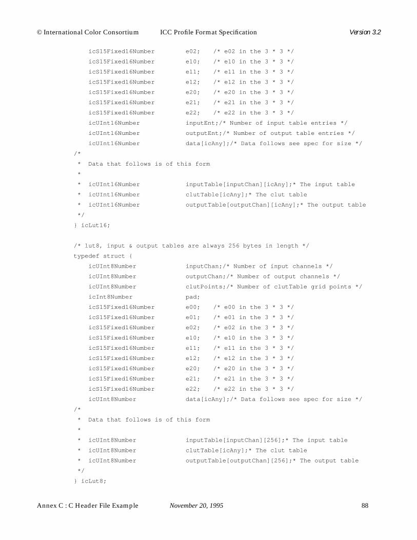
Annex C : C Header File Example November 20, 1995 88
© International Color Consortium ICC Profile Format Specification Version 3.2
icS15Fixed16Number e02; /* e02 in the 3 * 3 */
icS15Fixed16Number e10; /* e10 in the 3 * 3 */
icS15Fixed16Number e11; /* e11 in the 3 * 3 */
icS15Fixed16Number e12; /* e12 in the 3 * 3 */
icS15Fixed16Number e20; /* e20 in the 3 * 3 */
icS15Fixed16Number e21; /* e21 in the 3 * 3 */
icS15Fixed16Number e22; /* e22 in the 3 * 3 */
icUInt16Number inputEnt;/* Number of input table entries */
icUInt16Number outputEnt;/* Number of output table entries */
icUInt16Number data[icAny];/* Data follows see spec for size */
/*
* Data that follows is of this form
*
* icUInt16Number inputTable[inputChan][icAny];* The input table
* icUInt16Number clutTable[icAny];* The clut table
* icUInt16Number outputTable[outputChan][icAny];* The output table
*/
} icLut16;
/* lut8, input & output tables are always 256 bytes in length */
typedef struct {
icUInt8Number inputChan;/* Number of input channels */
icUInt8Number outputChan;/* Number of output channels */
icUInt8Number clutPoints;/* Number of clutTable grid points */
icInt8Number pad;
icS15Fixed16Number e00; /* e00 in the 3 * 3 */
icS15Fixed16Number e01; /* e01 in the 3 * 3 */
icS15Fixed16Number e02; /* e02 in the 3 * 3 */
icS15Fixed16Number e10; /* e10 in the 3 * 3 */
icS15Fixed16Number e11; /* e11 in the 3 * 3 */
icS15Fixed16Number e12; /* e12 in the 3 * 3 */
icS15Fixed16Number e20; /* e20 in the 3 * 3 */
icS15Fixed16Number e21; /* e21 in the 3 * 3 */
icS15Fixed16Number e22; /* e22 in the 3 * 3 */
icUInt8Number data[icAny];/* Data follows see spec for size */
/*
* Data that follows is of this form
*
* icUInt8Number inputTable[inputChan][256];* The input table
* icUInt8Number clutTable[icAny];* The clut table
* icUInt8Number outputTable[outputChan][256];* The output table
*/
} icLut8;

© International Color Consortium ICC Profile Format Specification Version 3.2
89 November 20, 1995 Annex C : C Header File Example
/* Measurement Data */
typedef struct {
icStandardObserver stdObserver;/* Standard observer */
icXYZNumber backing;/* XYZ for backing material */
icMeasurementGeometry geometry;/* Measurement geometry */
icMeasurementFlare flare; /* Measurement flare */
icIlluminant illuminant;/* Illuminant */
} icMeasurement;
/* Named color */
/*
* icNamedColor2 takes the place of icNamedColor, approved at the
* SIGGRAPH 95, ICC meeting.
*/
typedef struct {
icUInt32Number vendorFlag;/* Bottom 16 bits for IC use */
icUInt32Number count; /* Count of named colors */
icUInt32Number nDeviceCoords;/* Number of device coordinates */
icInt8Number prefix[32];/* Prefix for each color name */
icInt8Number suffix[32];/* Suffix for each color name */
icInt8Number data[icAny];/* Named color data follows */
/*
* Data that follows is of this form
*
* icInt8Number root1[32];* Root name for first color
* icUInt16Number pcsCoords1[icAny]; * PCS coordinates of first color
* icUInt16Number deviceCoords1[icAny]; * Device coordinates of firstcolor
* icInt8Number root2[32];* Root name for second color
* icUInt16Number pcsCoords2[icAny]; * PCS coordinates of first color
* icUInt16Number deviceCoords2[icAny]; * Device coordinates of firstcolor
* :
* :
* Repeat for name and PCS and device color coordinates up to (count-1)
*
* NOTES:
* PCS and device space can be determined from the header.
*
* PCS coordinates are icUInt16 numbers and are described in
* the ICC spec. Only 16 bit L*a*b* and XYZ are allowed. The number of
* coordinates is consistent with the headers PCS.

Annex C : C Header File Example November 20, 1995 90
© International Color Consortium ICC Profile Format Specification Version 3.2
*
* Device coordinates are icUInt16 numbers where 0x0000 represents
* the minimum value and 0xFFFF represents the maximum value.
* If the nDeviceCoords value is 0 this field is not given.
*/
} icNamedColor2;
/* Profile sequence structure */
typedef struct {
icSignature deviceMfg;/* Device Manufacturer */
icSignature deviceModel;/* Decvice Model */
icUInt64Number attributes;/* Device attributes */
icTechnologySignature technology;/* Technology signature */
icInt8Number data[icAny];/* Descriptions text follows */
/*
* Data that follows is of this form, this is an icInt8Number
* to avoid problems with a compiler generating bad code as
* these arrays are variable in length.
*
* icTextDescription deviceMfgDesc;* Manufacturer text
* icTextDescription modelDesc;* Model text
*/
} icDescStruct;
/* Profile sequence description */
typedef struct {
icUInt32Number count; /* Number of descriptions */
icUInt8Number data[icAny];/* Array of description struct */
} icProfileSequenceDesc;
/* textDescription */
typedef struct {
icUInt32Number count; /* Description length */
icInt8Number data[icAny];/* Descriptions follow */
/*
* Data that follows is of this form
*
* icInt8Number desc[count]* NULL terminated ascii string
* icUInt32Number ucLangCode;* UniCode language code
* icUInt32Number ucCount;* UniCode description length
* icInt16Number ucDesc[ucCount];* The UniCode description
* icUInt16Number scCode; * ScriptCode code
* icUInt8Number scCount;* ScriptCode count

© International Color Consortium ICC Profile Format Specification Version 3.2
91 November 20, 1995 Annex C : C Header File Example
* icInt8Number scDesc[67];* ScriptCode Description
*/
} icTextDescription;
/* Screening Data */
typedef struct {
icS15Fixed16Number frequency;/* Frequency */
icS15Fixed16Number angle; /* Screen angle */
icSpotShape spotShape;/* Spot Shape encodings below */
} icScreeningData;
typedef struct {
icUInt32Number screeningFlag;/* Screening flag */
icUInt32Number channels;/* Number of channels */
icScreeningData data[icAny];/* Array of screening data */
} icScreening;
/* Text Data */
typedef struct {
icInt8Number data[icAny];/* Variable array of characters */
} icText;
/* Structure describing either a UCR or BG curve */
typedef struct {
icUInt32Number count; /* Curve length */
icUInt16Number curve[icAny];/* The array of curve values */
} icUcrBgCurve;
/* Under color removal, black generation */
typedef struct {
icInt8Number data[icAny];/* The Ucr BG data */
/*
* Data that follows is of this form, this is a icInt8Number
* to avoid problems with a compiler generating bad code as
* these arrays are variable in length.
*
* icUcrBgCurve ucr; * Ucr curve
* icUcrBgCurve bg; * Bg curve
* icInt8Number string; * UcrBg description
*/
} icUcrBg;
/* viewingConditionsType */

Annex C : C Header File Example November 20, 1995 92
© International Color Consortium ICC Profile Format Specification Version 3.2
typedef struct {
icXYZNumber illuminant;/* In candelas per metre sq’d */
icXYZNumber surround;/* In candelas per metre sq’d */
icIlluminant stdIluminant;/* See icIlluminant defines */
} icViewingCondition;
/*------------------------------------------------------------------------*/
/*
* Tag Type definitions
*/
/*
* Many of the structures contain variable length arrays. This
* is represented by the use of the convention.
*
* typedata[icAny];
*/
/* The base part of each tag */
typedef struct {
icTagTypeSignature sig; /* Signature */
icInt8Number reserved[4];/* Reserved, set to 0 */
} icTagBase;
/* curveType */
typedef struct {
icTagBase base; /* Signature, “curv” */
icCurve curve; /* The curve data */
} icCurveType;
/* dataType */
typedef struct {
icTagBase base; /* Signature, “data” */
icData data; /* The data structure */
} icDataType;
/* dateTimeType */
typedef struct {
icTagBase base; /* Signature, “dtim” */
icDateTimeNumber date; /* The date */
} icDateTimeType;

© International Color Consortium ICC Profile Format Specification Version 3.2
93 November 20, 1995 Annex C : C Header File Example
/* lut16Type */
typedef struct {
icTagBase base; /* Signature, “mft2” */
icLut16 lut; /* Lut16 data */
} icLut16Type;
/* lut8Type, input & output tables are always 256 bytes in length */
typedef struct {
icTagBase base; /* Signature, “mft1” */
icLut8 lut; /* Lut8 data */
} icLut8Type;
/* Measurement Type */
typedef struct {
icTagBase base; /* Signature, “meas” */
icMeasurement measurement;/* Measurement data */
} icMeasurementType;
/* Named color type */
/* icNamedColor2Type, replaces icNamedColorType */
typedef struct {
icTagBase base; /* Signature, “ncl2” */
icNamedColor2 ncolor; /* Named color data */
} icNamedColor2Type;
/* Profile sequence description type */
typedef struct {
icTagBase base;/* Signature, “pseq” */
icProfileSequenceDesc desc;/* The seq description */
} icProfileSequenceDescType;
/* textDescriptionType */
typedef struct {
icTagBase base;/* Signature, “desc” */
icTextDescription desc; /* The description */
} icTextDescriptionType;
/* s15Fixed16Type */
typedef struct {
icTagBase base; /* Signature, “sf32” */
icS15Fixed16Array data; /* Array of values */
} icS15Fixed16ArrayType;

Annex C : C Header File Example November 20, 1995 94
© International Color Consortium ICC Profile Format Specification Version 3.2
typedef struct {
icTagBase base; /* Signature, “scrn” */
icScreening screen; /* Screening structure */
} icScreeningType;
/* sigType */
typedef struct {
icTagBase base; /* Signature, “sig” */
icSignature signature;/* The signature data */
} icSignatureType;
/* textType */
typedef struct {
icTagBase base; /* Signature, “text” */
icText data; /* Variable array of characters */
} icTextType;
/* u16Fixed16Type */
typedef struct {
icTagBase base; /* Signature, “uf32” */
icU16Fixed16Array data; /* Variable array of values */
} icU16Fixed16ArrayType;
/* Under color removal, black generation type */
typedef struct {
icTagBase base; /* Signature, “bfd “ */
icUcrBg data; /* ucrBg structure */
} icUcrBgType;
/* uInt16Type */
typedef struct {
icTagBase base; /* Signature, “ui16” */
icUInt16Array data; /* Variable array of values */
} icUInt16ArrayType;
/* uInt32Type */
typedef struct {
icTagBase base; /* Signature, “ui32” */
icUInt32Array data; /* Variable array of values */
} icUInt32ArrayType;
/* uInt64Type */
typedef struct {
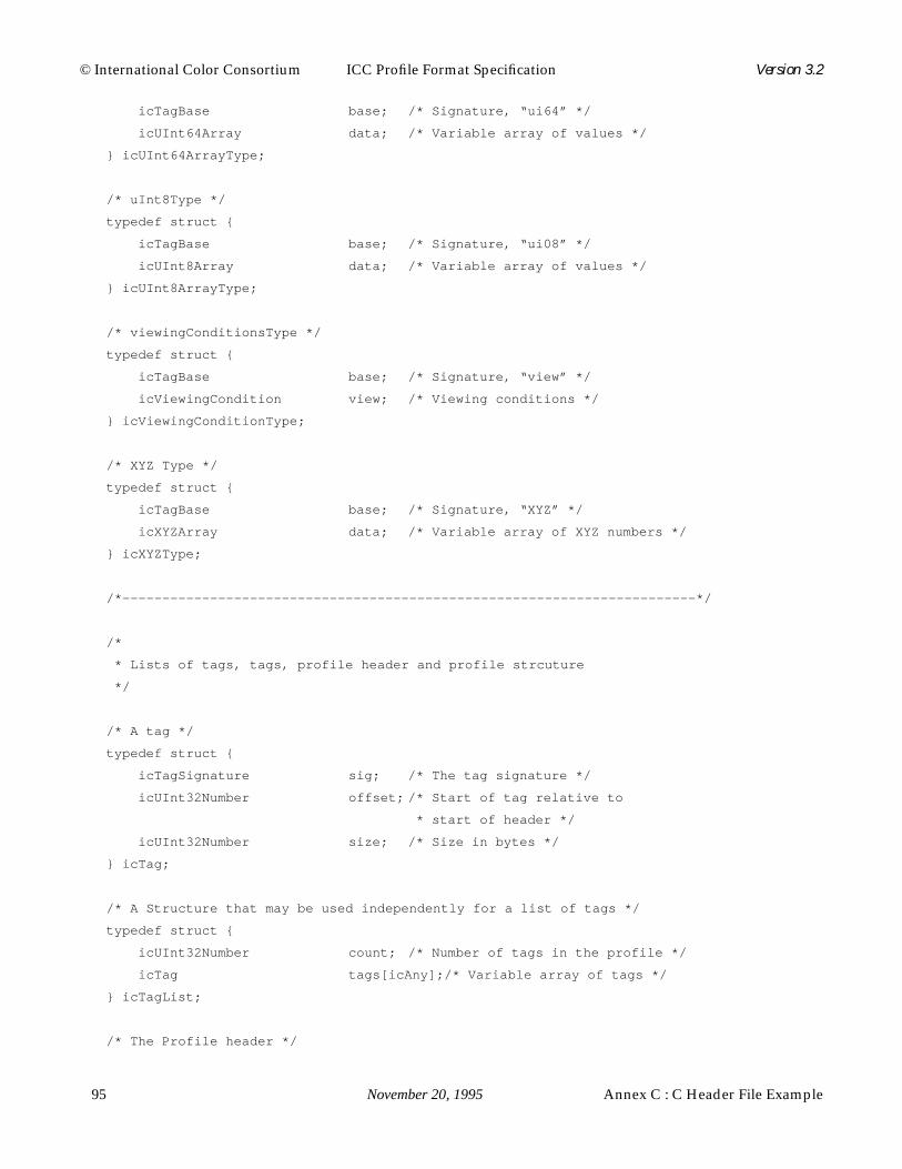
© International Color Consortium ICC Profile Format Specification Version 3.2
95 November 20, 1995 Annex C : C Header File Example
icTagBase base; /* Signature, “ui64” */
icUInt64Array data; /* Variable array of values */
} icUInt64ArrayType;
/* uInt8Type */
typedef struct {
icTagBase base; /* Signature, “ui08” */
icUInt8Array data; /* Variable array of values */
} icUInt8ArrayType;
/* viewingConditionsType */
typedef struct {
icTagBase base; /* Signature, “view” */
icViewingCondition view; /* Viewing conditions */
} icViewingConditionType;
/* XYZ Type */
typedef struct {
icTagBase base; /* Signature, “XYZ” */
icXYZArray data; /* Variable array of XYZ numbers */
} icXYZType;
/*------------------------------------------------------------------------*/
/*
* Lists of tags, tags, profile header and profile strcuture
*/
/* A tag */
typedef struct {
icTagSignature sig; /* The tag signature */
icUInt32Number offset; /* Start of tag relative to
* start of header */
icUInt32Number size; /* Size in bytes */
} icTag;
/* A Structure that may be used independently for a list of tags */
typedef struct {
icUInt32Number count; /* Number of tags in the profile */
icTag tags[icAny];/* Variable array of tags */
} icTagList;
/* The Profile header */

Annex C : C Header File Example November 20, 1995 96
© International Color Consortium ICC Profile Format Specification Version 3.2
typedef struct {
icUInt32Number size; /* Profile size in bytes */
icSignature cmmId; /* CMM for this profile */
icUInt32Number version;/* Format version number */
icProfileClassSignature deviceClass;/* Type of profile */
icColorSpaceSignature colorSpace;/* Color space of data */
icColorSpaceSignature pcs; /* PCS, XYZ or Lab only */
icDateTimeNumber date; /* Date profile was created */
icSignature magic; /* icMagicNumber */
icPlatformSignature platform;/* Primary Platform */
icUInt32Number flags; /* Various bit settings */
icSignature manufacturer;/* Device manufacturer */
icUInt32Number model; /* Device model number */
icUInt64Number attributes;/* Device attributes */
icUInt32Number renderingIntent;/* Rendering intent */
icXYZNumber illuminant;/* Profile illuminant */
icSignature creator;/* Profile creator */
icInt8Number reserved[44];/* Reserved for future use */
} icHeader;
/*
* A profile,
* we can’t use icTagList here because its not at the end of the structure
*/
typedef struct {
icHeader header; /* The header */
icUInt32Number count; /* Number of tags in the profile */
icInt8Number data[icAny];/* The tagTable and tagData */
/*
* Data that follows is of the form
*
* icTag tagTable[icAny];* The tag table
* icInt8Number tagData[icAny];* The tag data
*/
} icProfile;
/*------------------------------------------------------------------------*/
/* Obsolete entries */
/* icNamedColor was replaced with icNamedColor2 */
typedef struct {
icUInt32Number vendorFlag;/* Bottom 16 bits for IC use */
icUInt32Number count; /* Count of named colors */
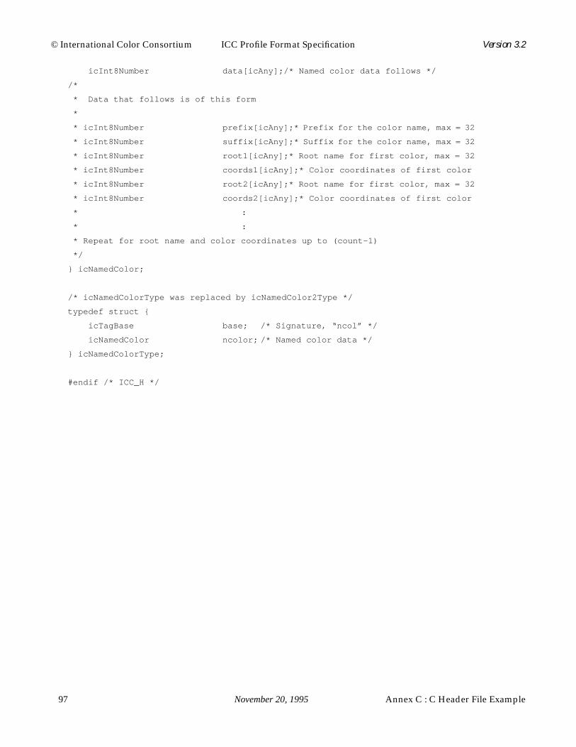
© International Color Consortium ICC Profile Format Specification Version 3.2
97 November 20, 1995 Annex C : C Header File Example
icInt8Number data[icAny];/* Named color data follows */
/*
* Data that follows is of this form
*
* icInt8Number prefix[icAny]; * Prefix for the color name, max = 32
* icInt8Number suffix[icAny]; * Suffix for the color name, max = 32
* icInt8Number root1[icAny]; * Root name for first color, max = 32
* icInt8Number coords1[icAny];* Color coordinates of first color
* icInt8Number root2[icAny]; * Root name for first color, max = 32
* icInt8Number coords2[icAny];* Color coordinates of first color
* :
* :
* Repeat for root name and color coordinates up to (count-1)
*/
} icNamedColor;
/* icNamedColorType was replaced by icNamedColor2Type */
typedef struct {
icTagBase base; /* Signature, “ncol” */
icNamedColor ncolor; /* Named color data */
} icNamedColorType;
#endif /* ICC_H */

Annex C : C Header File Example November 20, 1995 98
© International Color Consortium ICC Profile Format Specification Version 3.2
© International Color Consortium ICC Profile Format Specification Version 3.2
99 November 20, 1995 Annex D : PostScript Level 2 Tags
Annex D : PostScript Level 2 Tags
The PostScript Level 2 tags are provided in order to control exactly thePostScript Level 2 operations that should occur for a given profile. These tagsare only valid for PostScript Level 2 (and conceivably future versions ofPostScript) devices, and are not generally supported in PostScript Level 1devices. In addition, some of the tags may correspond to PostScript operationsthat are not supported in all PostScript Level 2 devices. Using such tags requiresfirst checking for the available operators. All operators described in thePostScript Language Reference Manual, second edition, are available on allPostScript Level 2 devices. Documentation for extensions to PostScript Level 2are available through Adobe's Developer Support Organization. In addition,guidelines for PostScript compatibility with this profile format are available. Fordetails of such operator support, compatibility guidelines, the PostScript Level 2device independent color model, or other PostScript-related issues contactAdobe's Developer Support Organization.
In general, there is a straightforward relationship between theprofile's header fields and tags, and these PostScript tags. It is anticipated thatthe various CMSs that support this profile format will also provide support forthese optional PostScript tags. To verify such support contact the CMS vendorsdirectly. In cases where such support is provided, and the desired model ofoperations is the same for PostScript processing as it is for CMS processing,these tags can be omitted, since all necessary information is in the profile itself.In the case where such CMS support is in question or processing different thanthat provided by an arbitrary CMS is desired, these tags can be populated toprovide exact control over the PostScript processing. For example, if private tagsare used in the profile to achieve a non-public type of processing on certainCMSs, such processing can be achieved on a PostScript device by populating theappropriate PostScript tags.
Some of the PostScript tags have a tag type of textType or uInt8Type.This choice is provided in order to match the properties of the communicationschannel to the data in these tags. Encoding the data in uInt8Type form isrecommended to save memory and/or reduce transmission times. Applicationsand drivers may convert it to ASCII Coded PostScript, Binary Coded PostScript,or Token Binary Coded PostScript or leave it in binary format to match therequirements of the communications channel. Applications and drivers areresponsible for this potential conversion from binary data to channel compatibledata. The data should be encoded in textType in those cases where the amountof data is relatively small or where the conversion from binary to channelcompatible data is not available.
The PostScript contained in these tags is not self evaluating - itsimply provides operands. These operands must be followed by operators like

Annex D : PostScript Level 2 Tags November 20, 1995 100
© International Color Consortium ICC Profile Format Specification Version 3.2
setcolorspace, setcolorrendering, and findcolorrendering.

© International Color Consortium ICC Profile Format Specification Version 3.2
101 November 20, 1995 Annex D : PostScript Level 2 Tags
Annex E : Profile Connection Space ExplanationNovember 20, 1995 102
© International Color Consortium ICC Profile Format Specification Version 3.2
Annex E : Profile Connection Space Explanation
E.1 Introduction
This Appendix is intended to clarify certain issues of interpretation in the ICCProfile Format.
The goal of color management is to provide the capability of maintainingcontrol over color rendering among various devices and media that may beinterconnected through a computer system or network. To achieve this goal, thecolor characteristics of each device are determined and encapsulated in a deviceprofile, which is a digital representation of the relation between devicecoordinates and a device-independent specification of color.
By device coordinates we mean the numerical quantities through which acomputer system communicates with a color peripheral—such as the digitalcode values used to drive a monitor or printer, or the digital signals receivedfrom a scanner. These quantities are usually labeled RGB (or CMYK), but thelabels identify the channels of the device rather than specific visual colors; thequantities are often encoded as unsigned 8-bit integers for each channel in thetypical digital interface.
The device-independent specification is best given in a color space based onhuman visual experience. Thus, a device profile provides a means of translating(or transforming) color image data from device coordinates into a visual colorspace or vice versa.
Furthermore, if the various profiles available to a color-managementsystem are referenced to the same visual color space, the system can translatedata from one device’s coordinates to another’s—while maintaining colorconsistency—by (conceptually) passing through the intermediary of the visualcolor space; the latter, then, constitutes a standard interface for colorcommunication, allowing profiles to be connected together in a meaningfulsequence. A color space used in this way may be termed a Profile ConnectionSpace (PCS). For example, the transformation of a color image from a scannerinto monitor coordinates can be described as a transformation into the PCS (viathe scanner’s device profile) followed by a transformation out of the PCS (via themonitor’s device profile). In practice, these successive transformations may beimplemented in a variety of ways, and the image may never actually berepresented in the PCS on disk or in computer memory. Thus, the PCS is to beregarded as a convenient reference for the definition of profiles—as anintermediate, or virtual, stage of the image processing—, in contrast to aninterchange or exchange color space, which is an encoding for the storage andtransmission of color images. The issues regarding the choice or design of a PCSare somewhat different from those related to an interchange space; this

© International Color Consortium ICC Profile Format Specification Version 3.2
103 November 20, 1995 Annex E : Profile Connection Space Explanation
Appendix is concerned only with PCS issues.
A PCS consists of a coordinate system for color space and aninterpretation of the data represented in that coordinate system. In fact, multiplecoordinate systems can easily be supported in the same or different color-management systems, as long as they share a common interpretation, since it isusually a well-defined and relatively simple mathematical task to transformfrom one coordinate system to another. However, if the interpretation of therepresented colors is different, there may be no satisfactory way of translatingthe data from one to another.
The purpose of this paper is to present an unambiguous interpretation forthe PCS implicit in the ICC Profile Format. It is especially important in theheterogeneous environments currently found on desktop platforms andnetworks to establish this interpretation in an open, non-proprietaryspecification, so that different color-management systems can communicate witheach other and exchange profiles within and across platforms and operatingsystems.
E.2 Colorimetry and Its Interpretation
The issue of interpretation has received little attention in the recent past, becauseit has been widely believed that the choice of a suitable coordinate system—preferably one founded on CIE colorimetry, a system of measurement andquantification of visual color stimuli created and promoted by the CommissionInternationale de l’Éclairage—would suffice to guarantee device independence.The notion was that colorimetric matching of the renderings on various mediawas the key to satisfactory color reproduction, and that interpretation was notneeded. However, although colorimetry can be an essential element of asuccessful approach to color management, it is usually necessary to modify thecolorimetric specification for renderings on different media.
Different media require different physical color stimuli, in certain cases,because they will be viewed in different environments—e.g., different surroundconditions or illuminants; the observers, therefore, will experience differentadaptive effects. In order to preserve the same color appearance in these differentenvironments, the colorimetry must be corrected to compensate for theadaptation of the human visual system and for physical differences in theviewing environments, such as flare. Although color appearance is still an activeresearch topic, the most common forms of adaptation are understood reasonablywell, so that the required corrections in the colorimetry for different viewingconditions can be modeled with sufficient accuracy.
There are other reasons why the colorimetry may be altered for specificmedia. For instance, hard-copy media—even those intended for the same viewingconditions—differ considerably in their dynamic range and color gamut. A well-

Annex E : Profile Connection Space ExplanationNovember 20, 1995 104
© International Color Consortium ICC Profile Format Specification Version 3.2
crafted rendering of an image on a specific medium will take advantage of thecapabilities of that medium without creating objectionable artifacts imposed byits limitations. For instance, the tone reproduction of the image should providesufficient contrast in the midtones without producing blocked-up shadows orwashed-out highlights. The detailed shape of the tone curve will depend on theminimum and maximum densities (Dmin and Dmax) attainable in the medium.Clearly, there is considerable art involved in shaping the tone-reproduction andcolor-reproduction characteristics of different media, and much of this art isbased on subjective, aesthetic judgments. As a result, the substrate (paper,transparency material, etc.) and the colorants used in a medium will beexploited to impart a particular “personality” to the reproduction that ischaracteristic of the medium.
Furthermore, the desired behavior of a color-management systemdepends strongly on artistic intent. If the output medium is identical to the inputmedium—say, 35-mm slides—, the desired behavior is typically to create aduplicate of the original. But if the two media are different, it is not so obviouswhat the default behavior should be. In some cases, the intent may be to retainall or part of the personality of the original; in other cases, it may be moreimportant to remove the personality of the original and replace it with a freshrendering that has the full personality of the output medium. Sometimes thesimulation of a third medium may be important—as when an image isdisplayed on a monitor to preview a rendering on a dye-diffusion printer,retaining (as well as possible) the personality of an original image scanned froma photographic print! It is essential to the success of color-management systemsthat a broad range of options be kept open. The interpretation of the PCS merelydefines the particular default behavior that will be facilitated by the systemwithout explicit intervention by the application or user. Alternative behaviorsare not excluded by this choice; they simply will not be the default and willrequire more work.
With this context in mind, we present the following interpretation:
The PCS represents desired color appearances.
Here, the term desired is used to indicate that the interpretation is orientedtowards colors to be produced on an output medium. It also is used to implythat these colors are not restricted by the limitations of any particular outputmedium. It is helpful here to conceptualize a “reference reproduction medium”,with a large gamut and dynamic range, as the target medium for the desiredcolors. Consequently, it is the responsibility of the output device profiles to clipor compress these colors into the gamut of the actual output media. And, ofcourse, “desired” also implies the expression of artistic intent.
The term color appearance is used to imply that adaptive effects are takeninto account. Associated with the reference reproduction medium is a “reference

© International Color Consortium ICC Profile Format Specification Version 3.2
105 November 20, 1995 Annex E : Profile Connection Space Explanation
viewing environment”. More precisely, therefore, the PCS represents the“desired color appearances” in terms of the CIE colorimetry of the colors to berendered on the reference medium and viewed in the reference environment. Outputprofiles for media that are viewed in different environments are responsible formodifying the colorimetry to account for the differences in the observer’s state ofadaptation (and any substantial differences in flare light present in theseenvironments), so that color appearance is preserved. Similarly, input profilesare responsible for modifying the colorimetry of the input media to account foradaptation and flare; they also have the responsibility to account for the artisticintent implicit in the word “desired”.
We define the reference reproduction medium as an idealized print, to beviewed in reflection, on a “paper” that is a perfect, non-selective diffuser (i.e.,Dmin = 0), with colorants having a large dynamic range and color gamut. Wedefine the reference viewing environment to be the standard viewing booth (ANSIPH-2.30); in particular, it is characterized by a “normal” surround—i.e., wherethe illumination of the image is similar to the illumination of the rest of theenvironment—, and the adapting illuminant is specified to have thechromaticity of D50 (a particular daylight illuminant).
E.3 Color Measurements
The PCS, so interpreted, represents colors for a hypothetical reference medium;device profiles must relate these colors to those that can be measured on realmedia. For consistency of results, these measurements must be made inaccordance with the principles of CIE colorimetry.
For one particular class of media (namely, those intended for the graphic-arts), the colorimetry should conform to graphic-arts standards for colormeasurement.1 Here, the illuminant is specified to be D50, so that no correctionsneed to be applied for chromatic adaptation. The colorimetry standard is basedon a theoretical D50 illuminant, as defined by the CIE in the form of a tabulatedspectral distribution. However, the fluorescent D50 simulators found in typicalprofessional viewing booths have rather different spectral distributions, and thecolor stimuli produced can be noticeably different.2 Often, better results can beobtained by basing the colorimetry on the actual, rather than the theoretical,illumination source; unfortunately, there is no standardized, practicallyrealizable source.
For other, non-graphic-arts media, the illuminant may be different from
1.IT8.7/3, “Graphic technology—Input data for characterization of 4-color process printing”, draft standardof Subcommittee 4 (Color) of ANSI Committee IT8 (Digital Data Exchange Standards), 14 December 1992,Paragraph 4.2.
2.D. Walker, “The Effects of Illuminant Spectra on Desktop Color Reproduction”, inDevice-IndependentColor Imaging, R. Motta and H. Berberian, ed.,Proc. SPIE,1909, 1993, pp. 236–246.

Annex E : Profile Connection Space ExplanationNovember 20, 1995 106
© International Color Consortium ICC Profile Format Specification Version 3.2
D50. In general, for best results, the actual illumination spectrum should be usedin the color measurements. And if the chromaticity of the illuminant is differentfrom that of D50, corrections for chromatic adaptation will be needed and willbe incorporated into the device-profile transforms. This aspect of the PCSinterpretation provides flexibility to the color-management system. For example,it will be possible to transform data from a medium intended for tungstenillumination to a medium intended for cool-white-fluorescent: the input profilehandles the adaptation from tungsten to D50, and the output profile handles theadaptation from D50 to cool-white.
Since substantial flare (perhaps 2–3%) may be present in an actualviewing environment,1 the colorimetry is defined in an ideal, flarelessmeasurement environment; in this way, difficult telescopic color measurementsin the viewing environment can be avoided, and simple contact instrumentsand/or controlled laboratory conditions can be used instead. (Correctionsshould be applied to the data for any appreciable flare in the actualmeasurement environment and instruments.)
E.4 Colorimetry Corrections and Adjustments in Output Profiles
The implications of this interpretation should be emphasized: the creator of aprofile is obliged to correct and adjust the PCS data for various effects. Since thePCS is interpreted with an output orientation, we will first examine the nature ofthese corrections and adjustments for output profiles. Then, in the next section,we will discuss the consequences for input profiles.
Let us look at a number of possible output paths:
E.5 Output to reflection print media
Included here are computer-driven printers, off-press proofing systems, offsetpresses, gravure printing, photographic prints, etc. These are generally intendedfor “normal” viewing environments; but corrections may be needed—e.g., forchromatic adaptation, if the illuminant’s chromaticity is other than that of D50.
In the simplest scenario, the user desires to reproduce colorscolorimetrically (aside from adaptive corrections) so as to attain an appearancematch. A distinction can be made between “absolute” and “relative” colorimetryin this context. Absolute colorimetry coincides with the CIE system: color stimuliare referenced to a perfectly reflecting diffuser. All reflection print media have areflectance less than 1.0 and cannot reproduce densities less than their particularDmin. In a cross-rendering task, the choice of absolute colorimetry leads to aclose appearance match over most of the tonal range, but, if the Dmin of the
1.R.W.G. Hunt,The Reproduction of Colour,Fourth Edition, Fountain Press, 1987, pp. 52–53.

© International Color Consortium ICC Profile Format Specification Version 3.2
107 November 20, 1995 Annex E : Profile Connection Space Explanation
input medium is different from that of the output medium, the areas of theimage that are left blank will be different. This circumstance has led to the use ofrelative colorimetry, in which the color stimuli are referenced to the paper (orother substrate). This choice leads to a cross-rendering style in which the outputimage may be lighter or darker overall than the input image, but the blank areaswill coincide. Both capabilities must be supported, since there are users in bothcamps. However, the default chosen for ICC is relative colorimetry.
This can be made more precise: the default “colorimetric” transform willeffectively apply a scaling operation in the CIE 1931 XYZ color space:
Xa= (Xmw / Xi) Xr (E1)
Ya = (Ymw / Yi) Yr (E2)
Za = (Zmw / Zi) Zr (E3)
where XYZr are the coordinates of a color in the PCS, (XYZ)a are thecoordinates of the corresponding color to be produced on the output medium,(XYZ)i are the coordinates of the lightest neutral represented in the PCS(namely, one with the chromaticity of D50 and a luminance of 1.0), and(XYZ)mw are the coordinates of the output paper (or other substrate) adapted tothe PCS illuminant (D50). Thus, the lightest neutral in the PCS will be rendered asblank paper—regardless of the reflectance or color cast of the paper—; otherneutrals and colors will be rescaled proportionately and will be rendered darkerthan the paper. Output on different reflection print media will then agree withthe PCS and with each other in relative colorimetry and, therefore, in relativeappearance.
In other cases, the preference may be for absolute colorimetry. This meansthat, within the limitations of the output medium, the CIE colorimetry of theoutput image should agree with values represented in the PCS. I.e., Xout = X,Yout = Y, and Zout = Z. One way of achieving this result is to apply a separatetransformation to the PCS values, outside of the device profile (e.g., inapplication or system software):
X’ = (XD50 / Xpaper) X (E4)
Y’ = (YD50 / Ypaper) Y (E5)
Z’ = (ZD50 / Zpaper) Z (E6)
The relative values, X’ Y’ Z’, can then be processed through the defaultcolorimetric transform (i.e., they are effectively substituted for XYZr inEquations 1–3) to achieve the desired result.
This capability depends on the availability to the color-management

Annex E : Profile Connection Space ExplanationNovember 20, 1995 108
© International Color Consortium ICC Profile Format Specification Version 3.2
software of the colorimetry of the paper. The mediaWhitePointTag in the profilecan be used for this purpose and should represent the adapted, absolutecolorimetry of the lightest neutral that the device and/or medium can render(usually the blank substrate).
In either case, it may happen that the dynamic range and/or color gamutof the output medium is not sufficient to encompass all the colors encoded in thePCS. Some form of clipping will then occur—in the highlights, in the shadows,or in the most saturated colors. While an appearance match may be achievedover much of a color space, there will be a loss of detail in some regions. If this isobjectionable, the operator should have an option for selecting a more explicitform of gamut compression to be applied to the colors as part of the outputprofile. ICC supports two styles of controlled gamut compression—“perceptual”and “saturation”—in addition to the “colorimetric” option, which clips abruptlyat the gamut boundary. (An important case requiring explicit gamutcompression is that of input from a transparency, where the dynamic range,even of the corrected colors, may exceed that of any reflection print medium.)Note that an explicit compression maps colors from the dynamic range andgamut of the reference medium to the range and gamut of the actual medium, sothat only (XYZ)D50—i.e., the lightest PCS neutral—will be rendered as blankpaper, just as in the relative-colorimetric case. This time, however, the entiretone scale may be readjusted, to keep the shadows from blocking up and tomaintain proper midtones, and some in-gamut colors may be adjusted to makeroom for out-of-gamut colors.
E.6 Output to transparency media
This category might include overhead transparencies and large-format color-reversal media, as well as slide-production systems. Transparency materials arenormally intended to be viewed by projection (using a tungsten lamp) in a dimor darkened room; in some cases, however, they are placed on a back-lit viewerfor display, and in others they are used as a graphic-arts input medium, inwhich case they are examined on a light box or light table with the aid of aloupe. Accordingly, there are several possible viewing conditions fortransparencies, requiring somewhat different corrections.
Typical color-reversal films have a much larger dynamic range thanreflection media and higher midscale contrast. Their tone-reproductioncharacteristics have evolved empirically, but it may be plausible to explain themas partially compensating for dark-surround adaptation and the flare conditionstypical in a projection room. The state of brightness adaptation in a projectionroom is also different from that in a reflection environment. To the extent thatthese explanations are valid, the colorimetry should be corrected for theseeffects. Furthermore, in some of these environments the visual system ispartially adapted to a tungsten source, and chromatic corrections should beapplied for the difference between tungsten and D50.

© International Color Consortium ICC Profile Format Specification Version 3.2
109 November 20, 1995 Annex E : Profile Connection Space Explanation
A “colorimetric” rendering, in this case, will actually produce anappearance match to the colors in the PCS, rather than a colorimetric match—i.e., the colors measured on the resulting transparency will differ from thoseencoded in the PCS, but will appear the same when the transparency is viewed inits intended environment as the PCS colors would if rendered on the referencemedium and viewed in reflection.
Note that the lightest neutral, (XYZ)D50,will be rendered at or near Dminof the transparency in the default (relative) colorimetric transform. An absolute-colorimetric rendering can be generated in software, as described above forreflection-print media.
Explicit gamut compression can be provided as an option; it normallywould not be needed for images input from photographic media, but it may beuseful for input from computer graphics, since some of the highly saturatedcolors available on a computer color monitor fall outside the gamut oftransparency media.
E.7 Negative media
Here the target colors are those of a reflection print to be made from thenegative. No adaptive corrections are required, unless the print is intended to beviewed under an illuminant other than D50. Explicit gamut compression is auseful option, and both relative and absolute colorimetric matches can beprovided as in the case of direct-print media.
E.8 Monitor display
The viewing conditions of a CRT monitor may require some corrections to thecolorimetry, due to the effects of surround and flare. Also, if the monitor’s whitepoint is other than D50, chromatic adaptation must be accounted for. Whencorrections for these effects are applied, the colors in the display should matchthe appearance of those in the PCS and should provide accurate and usefulfeedback to the operator.
In most cases, the rendering should be “colorimetric” (possibly includingadaptive corrections), in order to achieve this result. (As for reflection printmedia, this would be “relative” by default, but “absolute” colorimetry is alsosupported.) In other cases (video production, perhaps), it may be moreimportant to the user to create a pleasing image on the monitor (without havingout-of-gamut colors block up, for instance) than to preserve an appearancematch to the PCS; for that purpose, explicit gamut compression would be auseful option.
In many scenarios, the monitor display is not the end product, but rathera tool for an operator to use in controlling the processing of images for other

Annex E : Profile Connection Space ExplanationNovember 20, 1995 110
© International Color Consortium ICC Profile Format Specification Version 3.2
renderings. For this purpose, it will be possible to simulate on the monitor thecolors that would be obtained on various other output media. The PCS colorsare first transformed into the output-device coordinates, using any preferredstyle of gamut compression. Then they are transformed back to the PCS by usingthe (colorimetric) inverse output transform. (These two steps can be replaced byan equivalent “preview” transform.) Finally they are transformed(colorimetrically) into monitor coordinates for previewing. The result ofcompression to the output gamut should then be visible in the displayed image.
E.9 Colorimetry Corrections and Adjustments in Input Profiles
The purpose of an input profile is to transform an image into the PCS—i.e., tospecify the colors that are desired in the output. Since there are many possibleintentions that a user might have for these colors, we cannot impose manyrestrictions on the nature of the transforms involved. Bearing in mind thecapabilities of the output profiles, as just outlined, we can suggest thepossibilities available to various classes of input profiles.
E.10 Scanned reflection prints
Here the intended viewing environment may be identical to the reference, but, ifnot, adaptive corrections should be applied to the colorimetry. In the simplestcase, the profile may consist of a transformation from scanner signals to thecolorimetry of the medium. In this case, the personality of the input medium hasbeen preserved. If the output rendering is also “colorimetric”, the result will bean appearance match to the original. Indeed, if the output medium is the sameas the input medium, the result should be a close facsimile or duplicate of theoriginal.
By default, the rendering is based on relative colorimetry, as discussedabove. Therefore, it should be remembered, when creating an input profile, thatthe (XYZ)D50 point of the PCS will be mapped to the Dmin of the outputmedium. This implies that the Dmin of the input medium must be mapped tothe (XYZ)D50 point of the PCS, in order to facilitate the duplication of anoriginal and a relative-colorimetry match when cross-rendering.
In order to enable the alternative of absolute colorimetry, the “whitepoint” field in the header of the input profile should be used to specify thecolorimetry of the paper. This allows the absolute colorimetry of the original tobe computed from relative colorimetry represented in the PCS, by analogy toEquations 1–3 above. These absolute color stimuli can then be converted torelative colorimetry for output by using the “white point” field of the outputprofile in Equations 4–6.
There are other possibilities, however. The input profile could bedesigned to remove some or all of the personality of the input medium, so that

© International Color Consortium ICC Profile Format Specification Version 3.2
111 November 20, 1995 Annex E : Profile Connection Space Explanation
the PCS encoding makes use of more of the gamut and dynamic range of thereference medium. In these cases, it will probably be best to choose some form ofexplicit gamut compression in the output profile. The result may differ inappearance considerably from the original and will constitute a fresh renderingtuned to the capabilities and limitations of the output medium.
In any case, a calibrated color monitor, if available, can be used to displayan accurate preview of the result.
E.11 Scanned transparencies
Since transparencies are intended for viewing in a variety of environments,different kinds of adaptive corrections may be applied to the colorimetry of theinput medium to obtain colors in the PCS. For instance, the device profile mighttransform scanner signals into the colorimetry of a reference print that wouldhave the same appearance in the reference environment as the transparencyproduces in a projection environment. (Note that there may be no actualreflection print medium that has sufficient dynamic range to reproduce all ofthese color appearances). In this scenario, the personality of the color-reversalfilm or other transparency material is retained, even though the colorimetry hasbeen modified for the PCS; still, this may be loosely termed a “colorimetric”transform, since the only corrections are for flare and adaptation.
As in the case of input prints, there are other possibilities: some or all ofthe personality of the input medium can be removed, according to artistic intent,yielding different results, which also depend on the style of gamut compressionselected for output.
Normally, the Dmin of the input medium should be mapped to(XYZ)D50 in the PCS. The absolute, adapted XYZ of the Dmin color is recordedin the “medium white point” tag.
E.12 Scanned negatives
Photographic negatives, of course, are not intended for direct viewing.Therefore, the colorimetry that is relevant here might be that of a hypotheticalreflection print made from the negative and intended for viewing in thereference environment. No adaptive corrections should be applied. Thepersonality of the result is that of the negative-positive system as a whole.Again, other possibilities exist, depending on artistic intent.
E.13 Computer graphics
Such imagery is usually synthesized in the RGB space of a display monitor thatprovides visual feedback to the operator. Thus, adaptive corrections may need

Annex E : Profile Connection Space ExplanationNovember 20, 1995 112
© International Color Consortium ICC Profile Format Specification Version 3.2
to be applied to the colorimetry of the monitor to define the colorimetry of areference print having the same appearance.
The personality here is that of the synthetic image on the monitor screen.
E.14 Scene capture
This pathway refers to video cameras, electronic still cameras, and othertechnologies (such as Photo CD™) that provide a capability of approximatelydetermining the colorimetry of objects in a real-world scene. In most cases, thetone scale must be adjusted to provide enough contrast for viewing the referencemedium in the reference environment; the colorfulness of the image should alsobe enhanced somewhat for that environment. The personality of the result, ofcourse, depends on the nature of these adjustments.
E.15 Colorimetric input
In some cases, input colors are specified that are intended to be processedcolorimetrically, without any tone shaping or chromatic enhancement. Thismight be the case, for instance, when a scene-capture device is used to record thecolorimetry of real-world objects for scientific reasons, rather than for creating apleasing reproduction. It may also be the case when particular spot colors arespecified in colorimetric terms. In these cases, the specified colorimetric valuesare left intact in the transformation to the PCS; no adaptive corrections oradjustments are applied. The PCS values should be represented in relativecolorimetry, and the “white point” tag specifies the reference point for thescaling. In some cases this reference point will have a luminance of 1.0, and therewill be no difference between relative and absolute colorimetry. In other casesthe reference point will have the colorimetry of (say) the paper stock used in aspot-color sample book or of a particular light neutral in a scene. In most ofthese cases, the preferred output rendering will also be “colorimetric”. Bydefault, as before, this will entail relative colorimetry; absolute colorimetry canbe achieved, outside of the default transforms, by taking account of the “whitepoint” tags of the input and output profiles and converting appropriately.
An image of this kind can be said to have no personality.
As can be inferred from some of these examples, the user may have achoice of input profiles having different intents, as well as a choice amongoutput transforms having different intents. The end result depends on both ofthese choices, which, for the most predictable color reproduction, should bemade in coordination. To aid in this coordination, there are profile tags thatspecify the rendering intent and that distinguish between input transforms thatare colorimetric (aside from possible corrections for flare and adaptation) andthose that have applied adjustments to the colorimetry.
© International Color Consortium ICC Profile Format Specification Version 3.2
113 November 20, 1995 Annex E : Profile Connection Space Explanation
E.16 Techniques for Colorimetry Corrections
As we have seen, if the viewing conditions of the medium are different from thereference (e.g., projected slides or video viewed in dim or dark surround),corrections to the colorimetry of the reproduction should be applied.1 Theseshould be designed to correct for differences in the flare light present in theseenvironments, as well as the effects of non-normal surround, brightnessadaptation to the absolute radiant flux of the illumination, and any other effectsthat are found to be significant. And if the medium was intended to be viewedunder an illuminant of different chromaticity than that of D50, the profile shouldincorporate corrections for chromatic adaptation; these can simply be based on alinear scaling in XYZ (which happens automatically in the CIELAB system);alternatively, it can be based on the linear Von Kries transformation2 (or, ifpreferred, a more sophisticated, nonlinear model of color appearance, such asthat of Hunt3 or Nayatani4).
If the creators of device profiles universally apply these corrections totheir colorimetric data, the PCS will have a universal, unambiguousinterpretation, and images rendered “colorimetrically” will evoke (as nearly aspossible) the same appearance, regardless of the medium and viewingenvironment of the reproduction. In this way, the same image can be renderedon photographic transparency material, various reflective print media, CRT’s,etc., and will, by and large, appear similar to the viewer. This goal cannot beachieved simply by matching the colorimetry of the reproductions. Variousforms of explicit gamut compression and input effects can be made available forsituations where other goals are important; the recommended PCSinterpretation does not limit these possibilities in any way: it merely facilitatesthe default behavior of the color-management system.
1.Hunt,op. cit., pp. 56–61.
2.R.W.G. Hunt,Measuring Color, Ellis Horwood, pp. 70–71.
3.Ibid., pp. 146–173.
4.Y. Nayatani, K. Takahama, and H. Sobagaki, “Prediction of color appearance under various adapting con-ditions”, Color Res. Appl., 11, 62 (1986).
Recommended