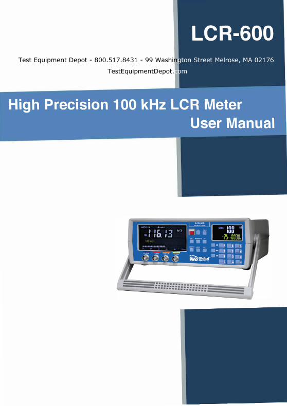
LCR-600
High Precision 100 kHz LCR Meter
User Manual
" 'j ,t'", :1 kl>
I l!.I, ,_,
"''"""'"''""umruu
Test Equipment Depot - 800.517.8431 - 99 Washington Street Melrose, MA 02176
TestEquipmentDepot.com
Table of Contents 1 Safety 2
1.1 Precautions 2 1.2 Compliance 4
2 Product Contents and Inspection 4
3 Introduction 5 3.1 Overview 5 3.2 Impedance Parameters 5 3.3 ESR or RP 7 3.4 Quality and Dissipation Factors 8
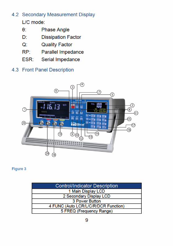
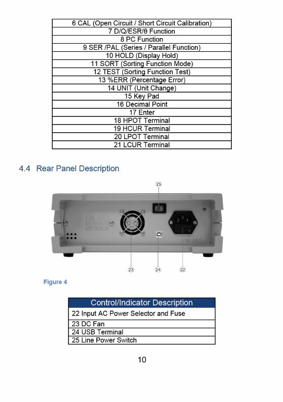
4 Product Description 8 4.1 Primary Measurement Display 8 4.2 Secondary Measurement Display 9 4.3 Front Panel Description 9 4.4 Rear Panel Description 10
5 Operating Instructions 11 5.1 Connecting the LCR-600 11 5.2 Powering On 11 5.3 Open Circuit / Short Circuit Compensation 11 5.4 Auto LCR Mode 12 5.5 Auto Mode 12 5.6 Measuring Inductance 13 5.7 Measuring Capacitance 13 5.8 Percentage Error 14 5.9 Sorting Function Mode 14 5.10 Display Hold Mode 15 5.11 Measuring Frequency 15
1
5.12 Measuring DC Resistance 15 5.13 Connecting to a Computer 15
6 Maintenance 15 6.1 Preventive Maintenance 15 6.2 Fuse Replacement 16 6.3 Cleaning 17
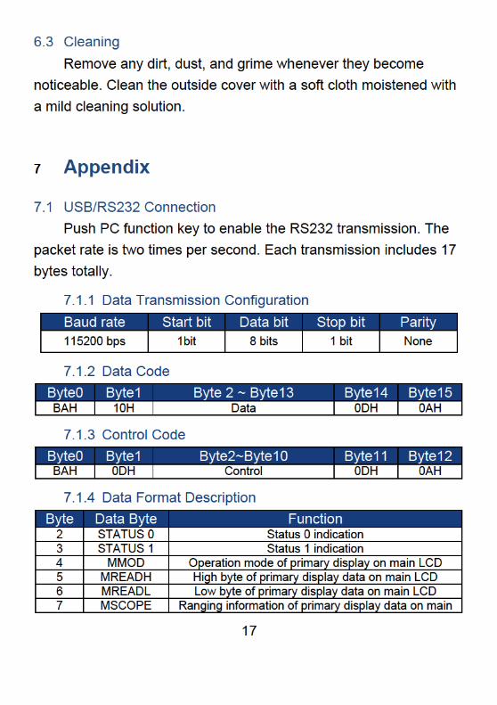
7 Appendix 17 7.1 USB/RS232 Connection 17
7.1.1 Data Transmission Configuration 17
7.1.2 Data Code 17
7.1.3 Control Code 17
7.1.4 Data Format Description 17
7.2 Open / Short Compensation 18 7.3 Selecting the Serial / Parallel Mode 19
7.3.1 Capacitor 20
7.3.2 Inductor 20
7.4 Calibration Sequence 21
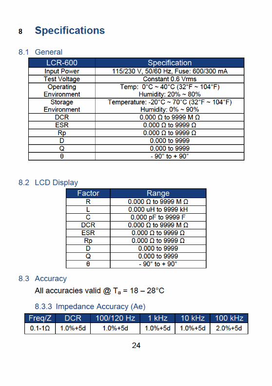
8 Specifications 24 8.1 General 24 8.2 LCD Display 24 8.3 Accuracy 24
8.3.3 Impedance Accuracy (Ae) 24
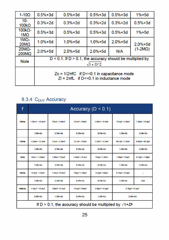
8.3.4 CDUT Accuracy 25
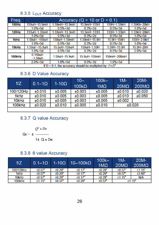
8.3.5 LDUT Accuracy 26
8.3.6 D Value Accuracy 26
2
8.3.7 Q value Accuracy 26
8.3.8 θ value Accuracy 26
8.3.9 Secondary Display Parameter Accuracy 27
9 Service and Warranty Information 28 9.1 Warranty 28 9.2 Calibration and Repair 29
1 Safety
1.1 Precautions WARNING: The normal use of test equipment involves a
certain amount of risk from electrical shock. The following general safety precautions must be observed during all phases of operation, service, and repair of this instrument. Failure to comply with these precautions or with specific warnings elsewhere in this manual violates the safety standards of the design, manufacture, and intended use of the instrument. The manufacturer assumes no liability for the customer’s failure to comply with these requirements.
You will significantly reduce the risk factor if you know and observe the following safety precautions:
• Don’t expose yourself to high voltage needlessly.• Remove housings and covers only when necessary.• Turn off equipment while making test connections on high
voltage circuits.
3
• Discharge high voltage capacitors after removing power.• If possible, familiarize yourself with the equipment beingtested and the location of its high voltage points. However,remember that high voltage may appear at unexpectedpoints in defective equipment.
• Use an insulated floor material or large insulated floor tostand on, and an insulated work surface on which to placeequipment. Make certain such surfaces are not damp orwet.
• Use the time proven “one hand in the pocket” techniquewhile handling an instrument probe.
• Be particularly careful to avoid contacting a nearby metalobject, which could provide an unwanted ground returnpath.
• When testing AC power equipment, remember that AC linevoltage is usually present on some power input circuits suchas the on-off switch, fuse, power transformer, etc. anytimethe equipment is connected to an AC outlet, even if theequipment is turned off.
• Some equipment with two-wire AC power cords, includingsome with polarized power plugs, are the “hot chassis” type.A plastic or wooden cabinet insulates the chassis to protectthe customer. When the cabinet is removed for servicing, aserious shock hazard exists if the chassis is touched.
• On test instruments, or any equipment with a 3-wire ACpower plug, use only a 3-wire outlet. This is a safety featureto keep the housing or other exposed elements grounded.
4
1.2 Compliance The LCR-600 is CE compliant.
2 Product Contents and Inspection This unit is tested prior to shipment. It is therefore ready for
immediate use upon receipt. An initial physical inspection should be made to ensure that no damage has been sustained during shipment.
Inspect the packing box on receipt for any external damage. If any external damage is evident, remove the instrument and visually inspect its case and parts for any damage. If damage to the instrument is evident, a description of the damage should be noted on the carrier’s receipt and signed by the driver or carrier agent. Save all shipping packaging for inspection. Forward a report of any damage to the agent through which the unit is procured.
Retain the original packing in case subsequent repackaging for return is required. Use of the original packing is essential.
After the mechanical inspection, verify the contents of the shipment. The items included in this package are:
• LCR Meter• Power Cord• User Manual• BNC Plug to Clip Lead Wire
Test Equipment Depot - 800.517.8431 - 99 Washington Street Melrose, MA 02176
TestEquipmentDepot.com
5
3 Introduction
3.1 Overview The LCR-600 is a high precision test instrument used for
measuring the inductance (L), capacitance (C), and resistance (R) of an electrical component.
The LCR-600 has an operational frequency range of 100 Hz to 100 kHz and basic measurement accuracy of 0.3%. There is a dual LCD display, measurement voltage fixed at 0.6 V, auto-detect function, and open-circuit /short-circuit compensation.
Use the LCR-600 to:
• Check ESR values of capacitors and inductors• Sort and/or select components• Measure unmarked and unknown components• Measure capacitance, inductance, or resistance of cables,
switches, circuit board foils, etc.
3.2 Impedance Parameters The LCR-600 provides both DC and AC impedance
measurements. Electrical impedance is the measurement of the opposition that a circuit presents to current when a voltage is applied.
6
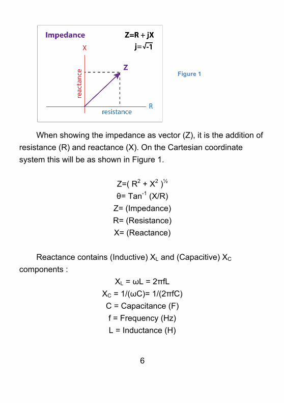
When showing the impedance as vector (Z), it is the addition of resistance (R) and reactance (X). On the Cartesian coordinate system this will be as shown in Figure 1.
Z=( R2 + X2 )½ θ= Tan-1 (X/R)
Z= (Impedance) R= (Resistance) X= (Reactance)
Reactance contains (Inductive) XL and (Capacitive) XC
components : XL = ωL = 2πfL
XC = 1/(ωC)= 1/(2πfC) C = Capacitance (F) f = Frequency (Hz) L = Inductance (H)
Figure 1
8
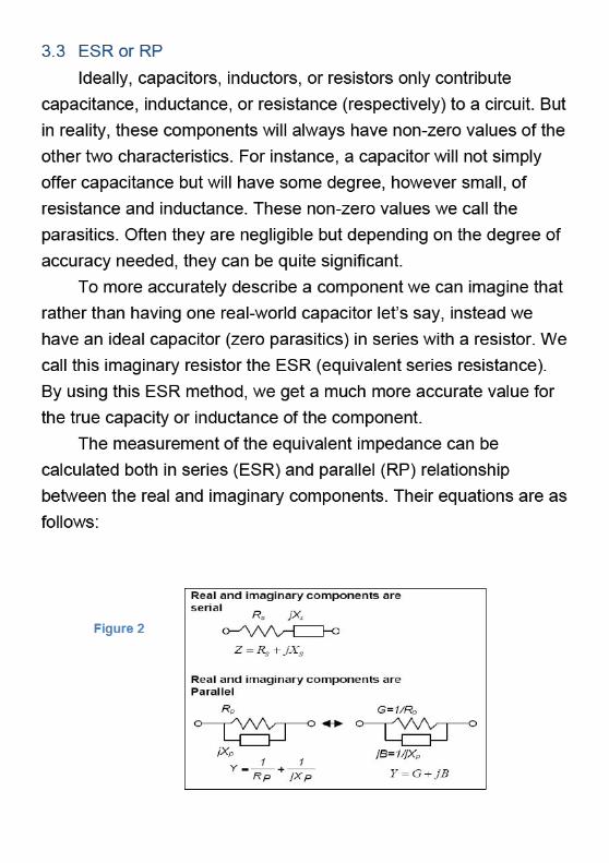
3.4 Quality and Dissipation Factors Other, secondary measurements of the LCR-600 include
Quality Factor (Q) and Dissipation Factor (D). These two measurements are actually reciprocals of each other. They refer to the damping characteristic of the electrical component. A higher Quality Factor (Q) means that the energy being transmitted through the component will “die out” more slowly. The component holds onto the energy longer. Dissipation Factor means just the opposite. It is a measure of how quickly the energy degrades.
Q = 1/D = ωLs/Rs = 1/ωCsRs = ωCpRp
Usually, Quality Factor (Q) relates to the inductance
measurement and the Dissipation Factor (D) relates to the capacitance measurement.
4 Product Description
4.1 Primary Measurement Display DCR: DC Resistance Lp: Parallel Inductance Ls: Serial Inductance Cp: Parallel Capacitance Cs: Serial Capacitance Rp: Parallel Resistance Rs: Serial Resistance
11
5 Operating Instructions
5.1 Connecting the LCR-600 Connect the power cable to your meter. Now connect the BNC
Plug to Clip Lead Wire to the BNC terminals on the LCR-600. Make sure that you connect according to the color bands.
5.2 Powering On LCR-600 has two power switches: Line Power Switch [25] on
the rear panel for the transformer and then the Power Button [3] on the front panel for the operational system.
Switch “ON” the Line Power Switch [25] on the rear panel then press the Power Button [3] on the front panel to light the LCD.
5.3 Open Circuit / Short Circuit Compensation LCR-600 provides open circuit and short circuit compensation
so that you can measure high resistance and low resistance more accurately. You must first calibrate these functions. Start by making sure the clip ends of the leads are not touching each other. Set the display at “OPEN” by pressing the CAL [6] key for 2 seconds. The main LCD will display [Open]. Then press CAL [6] again to start the open circuit calibration. The calibration will need about 30 seconds, after which the LCD will display [PASS]. The LCR-600 has now automatically finished the open circuit calibration.
Now for the short circuit calibration, connect the two clip ends of the lead together to create a short circuit. Press the CAL [6] key again for 2 seconds. The main LCD will display [Srt]. Now press the CAL [6] key again to start the short circuit calibration. As with the
open circuit calibration, wait 30 seconds. Afterwards, the LCD should display [PASS].
For more information about the purpose open circuit and short circuit compensation, see the appendix.
5.4 Auto LCR Mode Press FUNC [4] key until the main display shows [Auto LCR].
This is the “quick-start” or most basic measuring mode. In this mode you can connect a component to the leads and the meter will automatically identify the item as inductor, capacitor, or resistor and read out a measurement accordingly. Press the FREQ [5] key to select a different frequency range. The meter will automatically select parallel or serial mode for the component. You will not be able to switch this. You will also not be able to select the D/Q/ESR/θ factor. To have more flexibility to change these items, switch over to Auto Mode.
5.5 Auto Mode Press FUNC [4] key to change the function until the main LCD
displays [Auto]. There are actually three modes available: Auto for inductors, capacitors, and resistors. Keep pushing the FUNC [4] to shift between them. The meter will automatically default to series measuring. Therefore you will see Ls, Cs, and Rs consecutively. For parallel mode press the SER/PAL [9] after you have arrived at the correct series measurement (Ls, Cs, or Rs). Now the meter will read Lp, Cp, or Rp respectively).
12
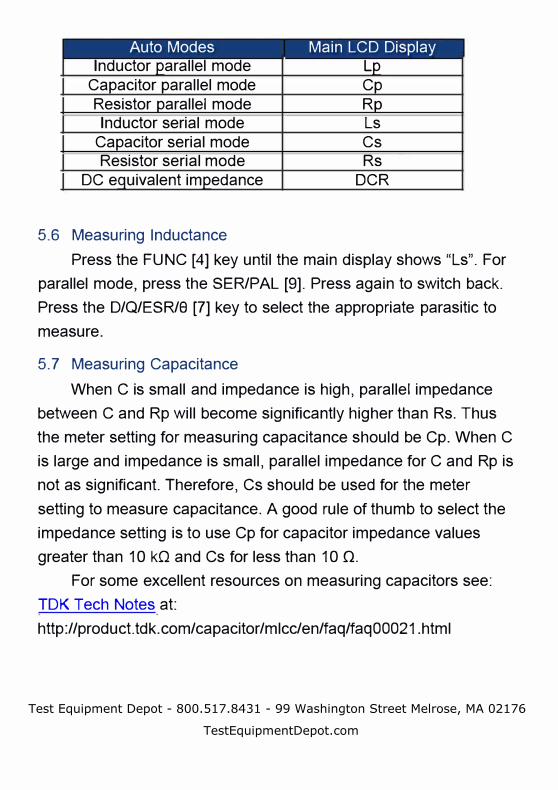
Auto Modes Main LCD Display Inductor parallel mode Lp
Capacitor parallel mode Cp Resistor parallel mode Ro Inductor serial mode Ls
Capacitor serial mode Cs Resistor serial mode Rs
DC equivalent impedance OCR
5.6 Measuring Inductance
Press the FUNC [4] key until the main display shows "Ls". For
parallel mode, press the SER/PAL [9]. Press again to switch back.
Press the D/Q/ESR/8 [7] key to select the appropriate parasitic to
measure.
5.7 Measuring Capacitance
When C is small and impedance is high, parallel impedance
between C and Rp will become significantly higher than Rs. Thus
the meter setting for measuring capacitance should be Cp. When C
is large and impedance is small, parallel impedance for C and Rp is
not as significant. Therefore, Cs should be used for the meter
setting to measure capacitance. A good rule of thumb to select the
impedance setting is to use Cp for capacitor impedance values
greater than 1 O kO and Cs for less than 1 O n.
For some excellent resources on measuring capacitors see:
TDK Tech Notes at:
http ://product. tdk. com/capacitor/mlcc/en/faq/faq00021 . html
Test Equipment Depot - 800.517.8431 - 99 Washington Street Melrose, MA 02176
TestEquipmentDepot.com

14
5.8 Percentage Error This function allows you to compare the value the meter is
displaying with a known or “theoretical” value. Take a measurement so that the screen is displaying a reading on the main display. Now press the REL [13], “Percentage Error” key. Enter the known or standard value onto the secondary display using the keypad. Now press the Enter [17] key. If the units must be changed, press UNIT [14] key to change the unit. Press the Enter [17] key again ifneeded. The secondary display will now give the difference betweenthe standard value and the measuring value in “%”. The equation isas follows:
% error = | experimental value – theoretical value | / theoretical value x 100%
Note: If the percentage error is higher than 9999%, the LCD will display only [----].
5.9 Sorting Function Mode The SORT function allows you to rapidly compare a reading to
an established tolerance for a PASS or FAIL test. For instance, if your capacitors should be within 1% of 100 µF, then you can connect a capacitor and the LCR-600 will read out PASS or FAIL.
Press the SORT key to enter the sorting function mode. Key in the maximum percentage error (1%) and press Enter [17] key. Key in the standard value (100 µF) and press Enter [17]. Connect a component (capacitor) to test. Wait until the primary display shows a value for the component being tested. Press the Test [12] key. The
15
secondary LCD will display [PASS] if the object is within the given tolerance or [FAIL] if not.
5.10 Display Hold Mode Press HOLD [10] key. The LCR-600 will hold the previously
recorded value. Press the HOLD [10] key again to release the value.
5.11 Measuring Frequency Press FREQ [5] key to select the measuring frequency. The
range can be one of five: 100 Hz,120 Hz,1 kHz, 10 kHz & 100 kHz.
5.12 Measuring DC Resistance Press FUNC [4] key to change the LCR-600 function until the
main LCD displays [DCR]. The LCR-600 is now under “DC Resistance Measuring Mode”.
5.13 Connecting to a Computer The LCR-600 has a USB jack for you to connect to a computer.
You will need to write your own software however, to link with the RS232 interface on the meter. Codes are provided in the appendix. Press PC [8] key. In the second LCD display will appear [RS232].
6 Maintenance
6.1 Preventive Maintenance Please follow the following preventive steps to ensure the
proper operation of your instrument.
• Never place heavy objects on the instrument.• Never place a hot soldering iron on or near the instrument.
16
• Never insert wires, pins, or other metal objects into theventilation fan.
• Never move or pull the instrument by the power cord orinput lead.
• Never move the instrument while power cord is connected.• Do not obstruct the ventilation holes in the rear panel as this
will increase the internal temperature.• Clean and check the calibration of the instrument on a
regular basis to keep the instrument looking nice andworking well.
• When the unit is not turning “ON”, check if the power switchis turned “ON”, or check the power cord. Make sure that thepower is properly connected to the unit and ensure the ACsupply at your site is the same as the mentioned at the rearchassis of the unit.
6.2 Fuse Replacement If the fuse blows, both LCDs will not light and the instrument will
not operate. Replace with the correct value fuse. The fuse is located on the rear panel adjacent to the power cord receptacle.
Remove the fuse holder assembly as follows.
• Unplug the power cord from the instrument.• Insert a small screwdriver in the fuse holder slot (location
between fuse holder and receptacle).• Change the fuse and re-insert the holder.Note: When re-inserting the fuse holder, be sure that the
correct line voltage is selected.
18
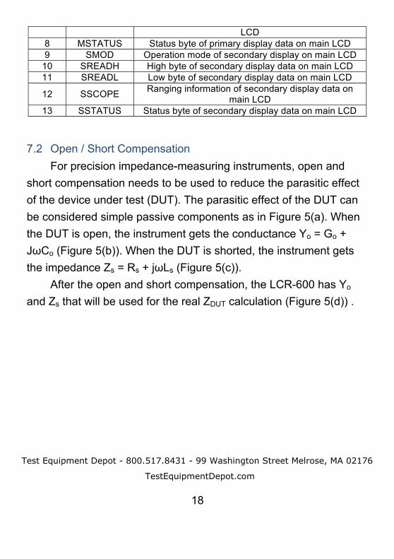
LCD 8 MSTATUS Status byte of primary display data on main LCD 9 SMOD Operation mode of secondary display on main LCD
10 SREADH High byte of secondary display data on main LCD 11 SREADL Low byte of secondary display data on main LCD
12 SSCOPE Ranging information of secondary display data on main LCD
13 SSTATUS Status byte of secondary display data on main LCD
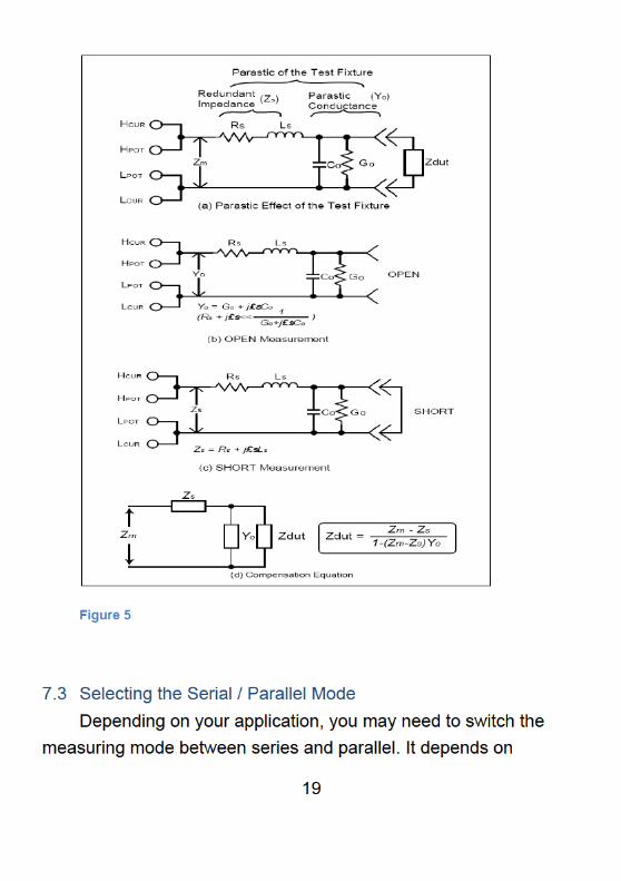
7.2 Open / Short Compensation For precision impedance-measuring instruments, open and
short compensation needs to be used to reduce the parasitic effect of the device under test (DUT). The parasitic effect of the DUT can be considered simple passive components as in Figure 5(a). When the DUT is open, the instrument gets the conductance Yo = Go + JωCo (Figure 5(b)). When the DUT is shorted, the instrument gets the impedance Zs = Rs + jωLs (Figure 5(c)).
After the open and short compensation, the LCR-600 has Yo and Zs that will be used for the real ZDUT calculation (Figure 5(d)) .
Test Equipment Depot - 800.517.8431 - 99 Washington Street Melrose, MA 02176
TestEquipmentDepot.com


23
9 Open / Short Calibration
After Step.8, the LCD will display [OPEN]. Keep 2 input tip at “OPEN” condition and press CAL key.
The LCD will flash 30sec and display [PASS], then short 2 input tip, the LCE will display [SRT]. Press CAL key, after 30sec. flash, the LCD will display [PASS], then go to step.10. If the LCD display
[FAIL], repeat step.9 again.
10 1KHz 10MΩ 10.000MΩ The same operation as step.1.
11 1KHz 1MΩ 1.0000MΩ
The same operation as step.1.After step.11, the LCR-600 will changed to 10KHz automatically. Go
to step.12.
12 10KHz 1MΩ 1.0000MΩ The same operation as step.1.
13 10KHz 100KΩ 100.00KΩ
The same operation as step.1. After step.13, the
LCD will display [100KHz] Go to step.14
14 100KHz 100KΩ 100.00KΩ
On this step, the resistor should be 100KΩ
/ 100KHz standard resistor. Operate as
step.1 15 100KHz 10KΩ 10.000KΩ Operate as step.1 16 100KHz 10Ω 10.000Ω Operate as step.1. 17 100KHz 1Ω 1.0000Ω Operate as step.1
18 After finished the calibration. The unit will power off automatically. Then please switch “OFF” the power switch and “OPEN” J11 and
cover the cabin.
19 After switching “ON” the unit again, the unit will return normal operation mode. Then press CAL key 2 sec to operate open
circuit/short circuit calibration.

27
8.3.9 Secondary Display Parameter Accuracy
• Ae = Impedance Accuracy• Definition: Q = 1/D• Rp = ESR (or Rs) x (1+1/D2)• D value accuracy De = ±Ae x (1+D)• ESR accuracy Re = ±Zm x Ae(Ω)• Zm = impedance calculated by 1/2πfC or 2πfL• Phase angle θ accuracy θe = ±(180/π) x Ae(deg)
Note: Specifications and information contained in this manual are subject to change without notice.
Test Equipment Depot - 800.517.8431 - 99 Washington Street Melrose, MA 02176
TestEquipmentDepot.com
28
9 Service and Warranty Information
9.1 Warranty Global Specialties warrants the LCR-600 to be free from
defective material or workmanship for a period of 2 year from date of original purchase. Under this warranty, Global Specialties is limited to repairing the defective device when returned to the factory, shipping charges prepaid, within the warranty period.
Units returned to Global Specialties that have been subject to abuse, misuse, damage or accident, or have been connected, installed or adjusted contrary to the instructions furnished by Global Specialties, or that have been repaired by unauthorized persons will not be covered by this warranty.
Global Specialties reserves the right to discontinue models, change specifications, price or design of this device at any time without notice and without incurring any obligation whatsoever.
The purchaser agrees to assume all liabilities for any damages and/or bodily injury which may result from the use or misuse of this device by the purchaser, his employees, or agents.
This warranty is in lieu of all other representations or warranties expressed or implied and no agent or representative of Global Specialties is authorized to assume any other obligation in connection with the sale and purchase of this device.
29
9.2 Calibration and Repair If you have a need for any calibration or repair services, please
visit us on the web at: globalspecialties.com. See the “Service” tab. Or contact us via the “Contact” tab. You may also contact us at:
Test Equipment Depot - 800.517.8431 - 99 Washington Street Melrose, MA 02176
TestEquipmentDepot.com

30

31
32
All rights reserved. No part of this book shall be reproduced, stored in a retrieval system, or transmitted by any means, electronic, mechanical, photocopying recording, or otherwise, without written permission from the publisher.
Copyright 2014 by Cal Test Electronics

Recommended