―1―
GReddy Turbo KitGReddy Turbo KitGReddy Turbo KitGReddy Turbo Kit
2007Nissan 350Z (VQ35HR)
Twin TD06-20G 8cm2
Tuner EditionTuner EditionTuner EditionTuner Edition
Custom tuning required for this kitCustom tuning required for this kitCustom tuning required for this kitCustom tuning required for this kit
―2―
2007 Nissan 350Z (VQ35HR) Twin TD06-20G 8cm2
Installation ManualInstallation ManualInstallation ManualInstallation Manual Please read the entire manual before installingPlease read the entire manual before installingPlease read the entire manual before installingPlease read the entire manual before installing this kit. this kit. this kit. this kit.
Application:
MakeMakeMakeMake Model Model Model Model ChassisChassisChassisChassis Year Year Year Year
Nissan 350ZNissan 350ZNissan 350ZNissan 350Z Z33 Z33 Z33 Z33 200 200 200 2007777
• Custom tuning required for this kitCustom tuning required for this kitCustom tuning required for this kitCustom tuning required for this kit
• This GReddy Turbo KitGReddy Turbo KitGReddy Turbo KitGReddy Turbo Kit is designed only for the vehicles specified above.
• Premium grade gasoline (91 octane or higher) is required with this Kit.
Important • This installation should only be performed by a trained specialist who is very familiar with the
automobile’s mechanical, electrical and fuel management system.
• If installed by an untrained person, it may cause damage to the kit as well as the vehicle.
• GReddy Performance Products Inc. is not responsible for any damage to the vehicle’s electrical system caused by improper installation.
• Make sure to follow the instruction and pay attention to the “Important”, “Warning!” and “Caution!” notice through out the instruction.
• Improper installation can be dangerous! Please make sure to inspect the installation before operating
the vehicle.
• Call your GReddy Authorized dealer or GReddy Performance Products if there are any problems or questions regarding this product.
―3―
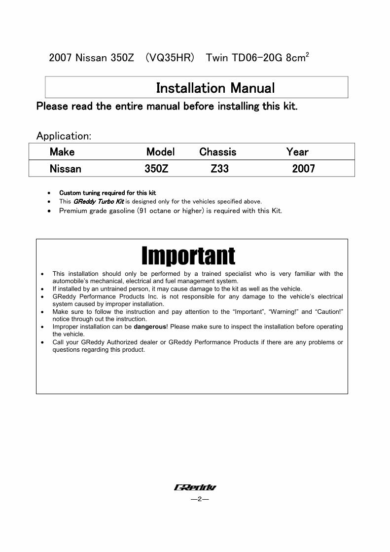
Parts ListParts ListParts ListParts List
1.Turbocharger TD06 SH-20G 8㎝2 (Right Side) 1
2.Turbocharger TD06 SH-20G 8㎝2 (Left Side) 1
3.Intercooler Type29 1
4.Waste gate (GReddy/TAIL) 0.45bar 2
5.Exhaust Manifold (Right Side) Ductile Iron Cast 1
6.Exhaust Manifold (Left Side) Ductile Iron Cast 1
7.Down Pipe (Right Side) (SS 60φ) 1
8.Down Pipe (Left Side) (SS 60φ) 1
9.Waste gate Inlet Pipe (Right Side) (SUS42.7φ) 1
10.Waste gate Inlet Pipe (Left Side) (SUS42.7φ) 1
11.Waste gate Open pipe (Right Side) (SUS42.7φ) 1
12.Waste gate Open pipe (Left Side) (SUS42.7φ) 1
13.Waste gate Bracket (Right Side) 1
14.Waste gate Bracket (Left Side) 1
15.Waste gate Bracket (Center) 1
16.Compression Pipe C-C-C-C-1111 (50φAluminum) 1
17. 〃 C-C-C-C-2222 (50φAluminum) 1
18. 〃 C-C-C-C-3333 (60φAluminum) 1
19. 〃 C-C-C-C-4444 (70φAluminum) 1
20. 〃 C-C-C-C-5555 (50φAluminum) 1
21. 〃 C-C-C-C-6666 (50φAluminum) 1
22. 〃 C-C-C-C-7777 (60φAluminum) 1
23. 〃 C-C-C-C-8888 (70φAluminum) 1
24.Suction Pipe S-S-S-S-1111 (70φAluminum) 1
25. 〃 S-S-S-S-2222 (70φAluminum) 1
26.AIRINX AY‐SB (Blue) 2
27.AIRINX Hose Adapter S70 2
―4―
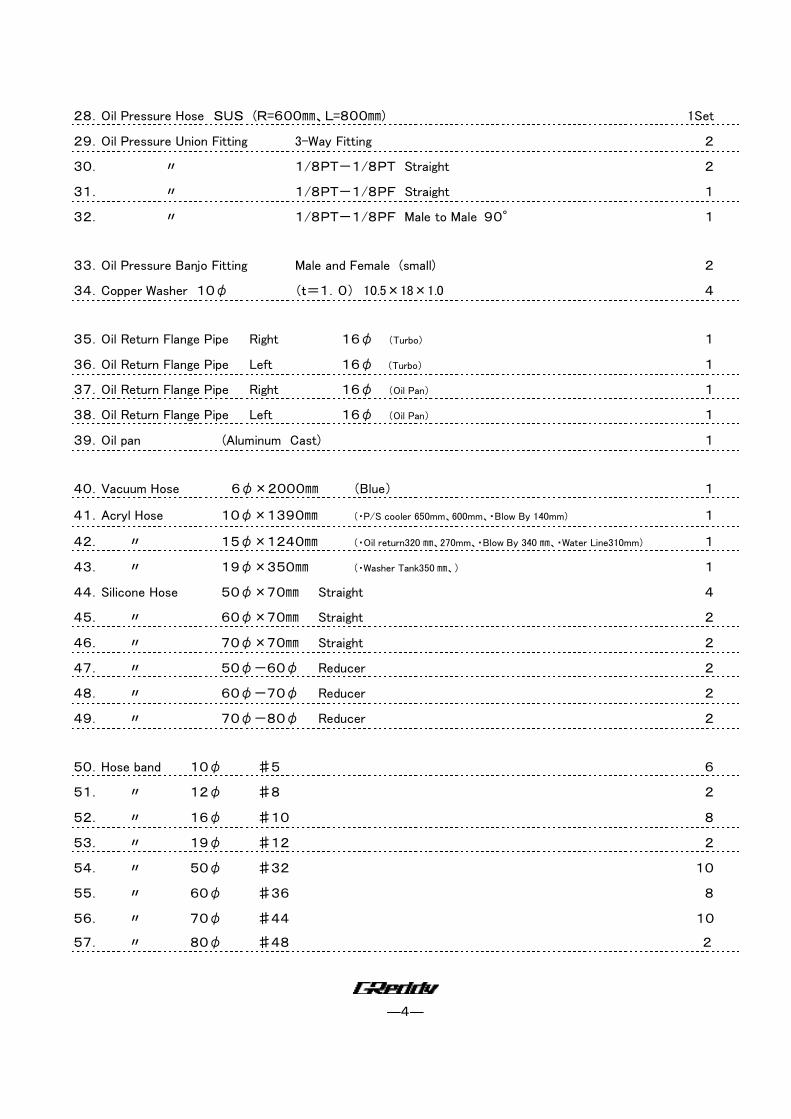
28.Oil Pressure Hose SUS (R=600㎜、L=800㎜) 1Set
29.Oil Pressure Union Fitting 3-Way Fitting 2
30. 〃 1/8PT-1/8PT Straight 2
31. 〃 1/8PT-1/8PF Straight 1
32. 〃 1/8PT-1/8PF Male to Male 90° 1
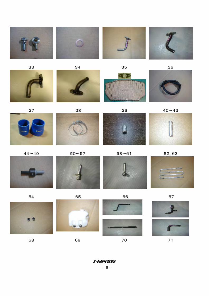
33.Oil Pressure Banjo Fitting Male and Female (small) 2
34.Copper Washer 10φ (t=1.0) 10.5×18×1.0 4
35.Oil Return Flange Pipe Right 16φ (Turbo) 1
36.Oil Return Flange Pipe Left 16φ (Turbo) 1
37.Oil Return Flange Pipe Right 16φ (Oil Pan) 1
38.Oil Return Flange Pipe Left 16φ (Oil Pan) 1
39.Oil pan (Aluminum Cast) 1
40.Vacuum Hose 6φ×2000㎜ (Blue) 1
41.Acryl Hose 10φ×1390㎜ (・P/S cooler 650mm、600mm、・Blow By 140mm) 1
42. 〃 15φ×1240㎜ (・Oil return320 ㎜、270mm、・Blow By 340 ㎜、・Water Line310mm) 1
43. 〃 19φ×350㎜ (・Washer Tank350 ㎜、) 1
44.Silicone Hose 50φ×70㎜ Straight 4
45. 〃 60φ×70㎜ Straight 2
46. 〃 70φ×70㎜ Straight 2
47. 〃 50φ-60φ Reducer 2
48. 〃 60φ-70φ Reducer 2
49. 〃 70φ-80φ Reducer 2
50.Hose band 10φ ♯5 6
51. 〃 12φ ♯8 2
52. 〃 16φ ♯10 8
53. 〃 19φ ♯12 2
54. 〃 50φ ♯32 10
55. 〃 60φ ♯36 8
56. 〃 70φ ♯44 10
57. 〃 80φ ♯48 2
―5―
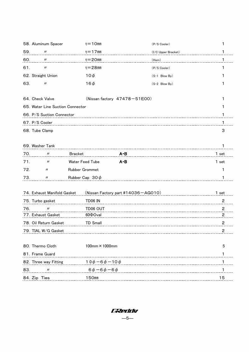
58.Aluminum Spacer t=10㎜ (P/S Cooler) 1
59. 〃 t=17㎜ (I/C Upper Bracket) 1
60. 〃 t=20㎜ (Horn) 1
61. 〃 t=28㎜ (P/S Cooler) 1
62.Straight Union 10φ (S-1 Blow By) 1
63. 〃 16φ (S-2 Blow By) 1
64.Check Valve (Nissan factory 47478-51E00) 1
65.Water Line Suction Connector 1
66.P/S Suction Connector 1
67.P/S Cooler 1
68.Tube Clamp 3
69.Washer Tank 1
70. 〃 Bracket AAAA・・・・BBBB 1 set
71. 〃 Water Feed Tube AAAA・・・・BBBB 1 set
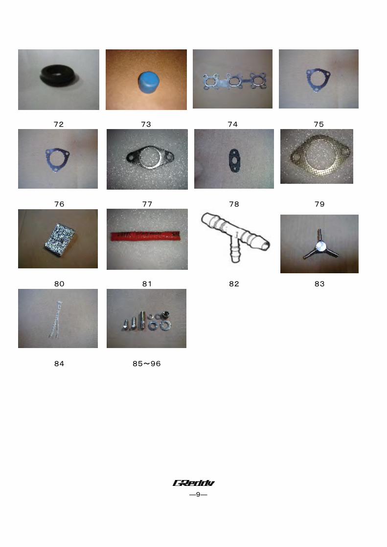
72. 〃 Rubber Grommet 1
73. 〃 Rubber Cap 30φ 1
74.Exhaust Manifold Gasket (Nissan Factory part #14036-AG010) 1 set
75.Turbo gasket TD06 IN 2
76. 〃 TD06 OUT 2
77.Exhaust Gasket 60ΦOval 2
78.Oil Return Gasket TD Small 2
79.TIAL W/G Gasket 2
80.Thermo Cloth 100mm×1000mm 5
81.Frame Guard 1
82.Three way Fitting 1 0φ-6φ-10φ 1
83. 〃 6φ-6φ-6φ 1
84.Zip Ties 150㎜ 15
―6―
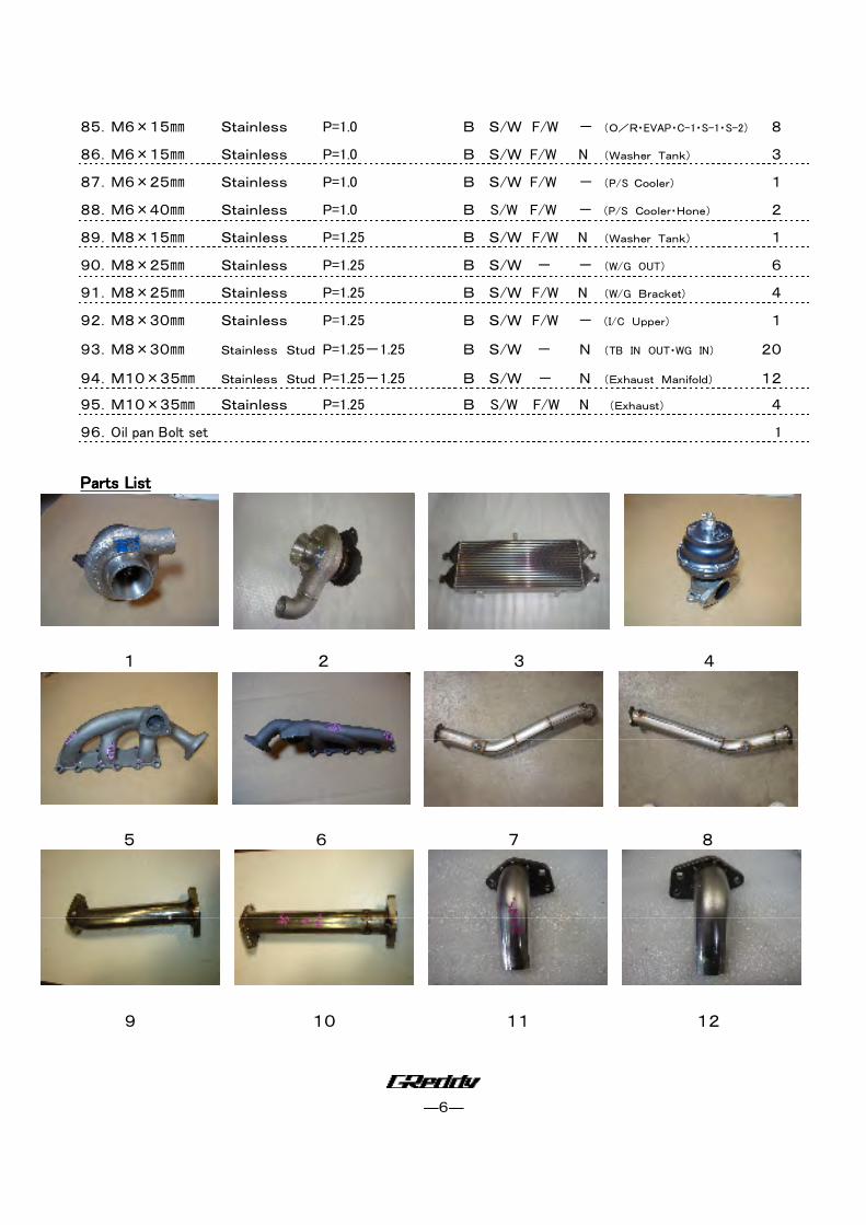
85.M6×15㎜ Stainless P=1.0 B S/W F/W - (O/R・EVAP・C-1・S-1・S-2) 8
86.M6×15㎜ Stainless P=1.0 B S/W F/W N (Washer Tank) 3
87.M6×25㎜ Stainless P=1.0 B S/W F/W - (P/S Cooler) 1
88.M6×40㎜ Stainless P=1.0 B S/W F/W - (P/S Cooler・Hone) 2
89.M8×15㎜ Stainless P=1.25 B S/W F/W N (Washer Tank) 1
90.M8×25㎜ Stainless P=1.25 B S/W - - (W/G OUT) 6
91.M8×25㎜ Stainless P=1.25 B S/W F/W N (W/G Bracket) 4
92.M8×30㎜ Stainless P=1.25 B S/W F/W - (I/C Upper) 1
93.M8×30㎜ Stainless Stud P=1.25-1.25 B S/W - N (TB IN OUT・WG IN) 20
94.M10×35㎜ Stainless Stud P=1.25-1.25 B S/W - N (Exhaust Manifold) 12
95.M10×35㎜ Stainless P=1.25 B S/W F/W N (Exhaust) 4
96.Oil pan Bolt set 1
Parts ListParts ListParts ListParts List
1 2 3 4
5 6 7 8
9 10 11 12
―7―
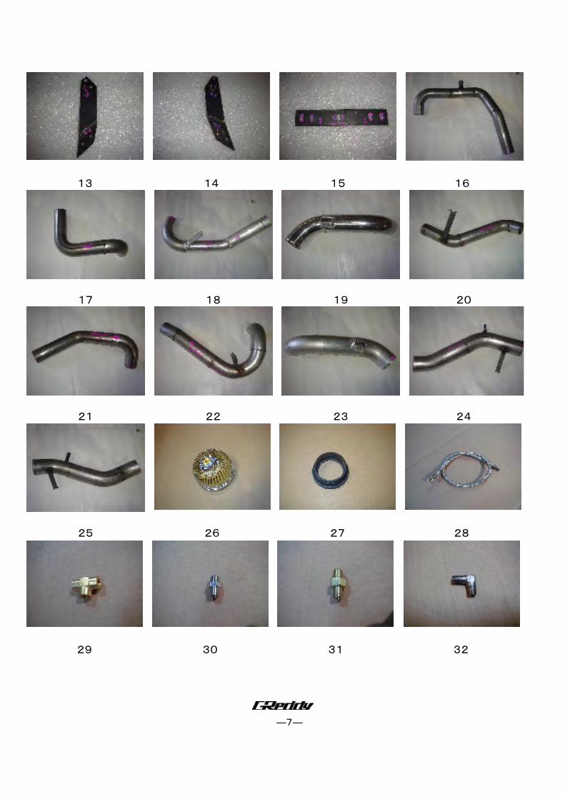
13 14 15 16
17 18 19 20
21 22 23 24
25 26 27 28
29 30 31 32
―8―
33 34 35 36
37 38 39 40~43
44~49 50~57 58~61 62、63
64 65 66 67
68 69 70 71
―9―
72 73 74 75
76 77 78 79
80 81 82 83
84 85~96
―10―
2. Factory Parts Removal2. Factory Parts Removal2. Factory Parts Removal2. Factory Parts Removal
When removing the stock parts, make sure you read over the factory repair manual When removing the stock parts, make sure you read over the factory repair manual When removing the stock parts, make sure you read over the factory repair manual When removing the stock parts, make sure you read over the factory repair manual
for proper procedures.for proper procedures.for proper procedures.for proper procedures.
2-1 Disconnect the negative terminal of the battery.
2-2 Remove the under engine cover.
2-3 Drain the engine oil, coolant and power steering fluid.
2-4 Disconnect the air flow meter.
2-5 Remove the Air cleaner assembly with airflow meter, intake tube, and breather hose.
2-6 Remove the Top Radiator Hose and the Water Pipe (Located above the Right Exhaust
manifold).
2-7 Disconnect the primary and secondary O2 sensor and remove the exhaust manifold and
catalytic converter.
2-8 Remove the exhaust manifold.
2-9 Remove oil pan (Please refer to the factory service manual for detail instructions f or
removing the oil pan.)
2-10 Remove the upper intake manifold collector, fuel rail assembly with injectors and regulator.
2-11 Remove the front bumper.
2-12 Remove the bumper reinforcement.
2-13 Remove the left and the right side horn.
2-14 Remove the Power steering fluid cooler.
―11―
3. Turbo Kit Installation3. Turbo Kit Installation3. Turbo Kit Installation3. Turbo Kit Installation
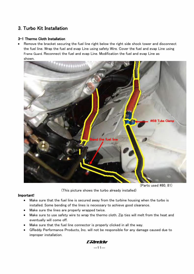
3333----1 1 1 1 Thermo Cloth Installation Thermo Cloth Installation Thermo Cloth Installation Thermo Cloth Installation
• Remove the bracket securing the fuel line right below the right side shock tower and disconnect
the fuel line. Wrap the fuel and evap Line using safety Wire. Cover the fuel and evap Line using
Frame Guard. Reconnect the fuel and evap Line. Modification the fuel and evap Line as
shown.
(Parts used #80, 81)
(This picture shows the turbo already installed)
Important!Important!Important!Important!
• Make sure that the fuel line is secured away from the turbine housing when the turbo is
installed. Some bending of the lines is necessary to achieve good clearance.
• Make sure the lines are properly wrapped twice.
• Make sure to use safety wire to wrap the thermo cloth. Zip ties will melt from the heat and
eventually will come off.
• Make sure that the fuel line connector is properly clicked in all the way.
• GReddy Performance Products, Inc. will not be responsible for any damage caused due to
improper installation.
Bend the fuel lineBend the fuel lineBend the fuel lineBend the fuel line
####68686868 Tube ClampTube ClampTube ClampTube Clamp
―12―
CauCauCauCaution!tion!tion!tion!
• Make sure to check and double check this step. This is the most important step in this install. Make sure to check and double check this step. This is the most important step in this install. Make sure to check and double check this step. This is the most important step in this install. Make sure to check and double check this step. This is the most important step in this install.
• Without proper clearance and thermo wrapping the fuel lines, the fuel line connector can melt Without proper clearance and thermo wrapping the fuel lines, the fuel line connector can melt Without proper clearance and thermo wrapping the fuel lines, the fuel line connector can melt Without proper clearance and thermo wrapping the fuel lines, the fuel line connector can melt
from heat and may catch on fire. from heat and may catch on fire. from heat and may catch on fire. from heat and may catch on fire.
• Wrap the Starter and the Wrap the Starter and the Wrap the Starter and the Wrap the Starter and the Main Engine harness right Main Engine harness right Main Engine harness right Main Engine harness right
above the transmission bell housing. above the transmission bell housing. above the transmission bell housing. above the transmission bell housing.
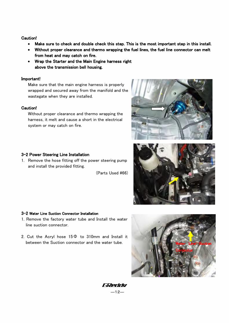
Important!Important!Important!Important!
Make sure that the main engine harness is properly
wrapped and secured away from the manifold and the
wastegate when they are installed.
Caution!Caution!Caution!Caution!
Without proper clearance and thermo wrapping the
harness, it melt and cause a short in the electrical
system or may catch on fire.
3333----2 2 2 2 Power Steering Line InstallationPower Steering Line InstallationPower Steering Line InstallationPower Steering Line Installation
1. Remove the hose fitting off the power steering pump
and install the provided fitting.
(Parts Used #66)
3333----2222 WWWWater Line Suction Connector ater Line Suction Connector ater Line Suction Connector ater Line Suction Connector InstallationInstallationInstallationInstallation
1. Remove the factory water tube and Install the water
line suction connector.
2. Cut the Acryl hose 15Φ to 310mm and Install it
between the Suction connector and the water tube.
Water Line Suction Water Line Suction Water Line Suction Water Line Suction
ConnectorConnectorConnectorConnector
―13―
Left Side (Driver’s Side)
Install Stud Bolt
Fro
nt
of
the
en
gin
e
Right Side (Passenger’s Side)
Fro
nt o
f
the e
ngin
e
Install Stud Bolt
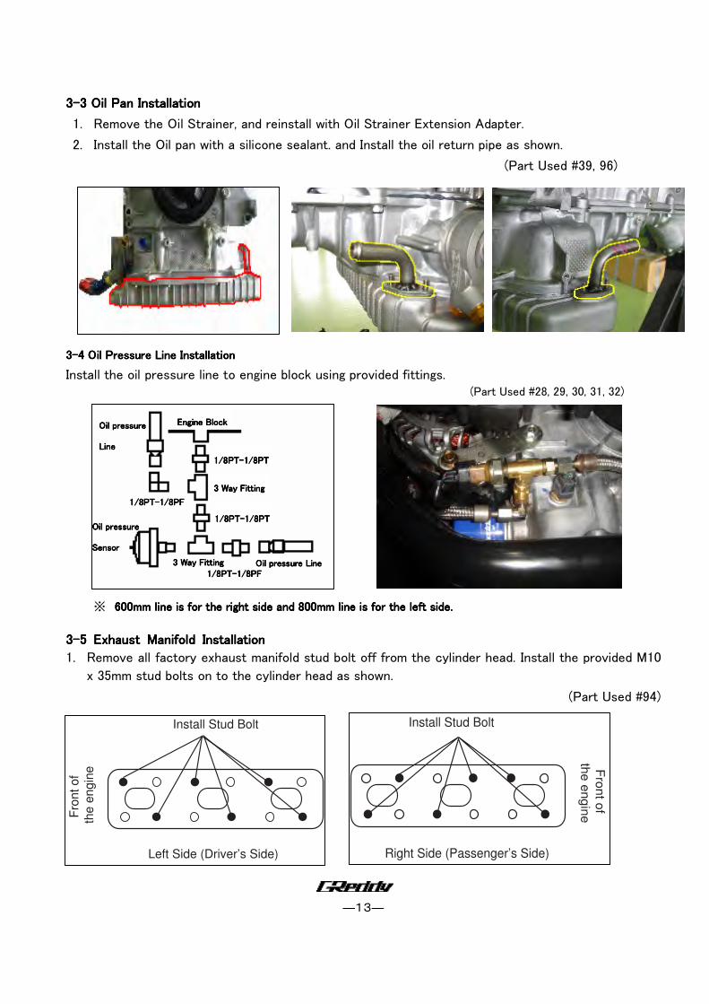
3333----3 3 3 3 Oil Pan InstallationOil Pan InstallationOil Pan InstallationOil Pan Installation
1. Remove the Oil Strainer, and reinstall with Oil Strainer Extension Adapter.
2. Install the Oil pan with a silicone sealant. and Install the oil return pipe as shown.
(Part Used #39, 96)
3333----4 4 4 4 Oil Pressure Line InstallationOil Pressure Line InstallationOil Pressure Line InstallationOil Pressure Line Installation
Install the oil pressure line to engine block using provided fittings. (Part Used #28, 29, 30, 31, 32)
※ 600mm line is for the right side and 800mm line is for the left side. 600mm line is for the right side and 800mm line is for the left side. 600mm line is for the right side and 800mm line is for the left side. 600mm line is for the right side and 800mm line is for the left side.
3333----5 5 5 5 Exhaust Manifold InstallationExhaust Manifold InstallationExhaust Manifold InstallationExhaust Manifold Installation
1. Remove all factory exhaust manifold stud bolt off from the cylinder head. Install the provided M10
x 35mm stud bolts on to the cylinder head as shown.
(Part Used #94)
3 Way Fitting3 Way Fitting3 Way Fitting3 Way Fitting
3 Way Fitting3 Way Fitting3 Way Fitting3 Way Fitting
Engine BlockEngine BlockEngine BlockEngine Block
1/8PT1/8PT1/8PT1/8PT----1/8PT1/8PT1/8PT1/8PT
1/8PT1/8PT1/8PT1/8PT----1/8PT1/8PT1/8PT1/8PT
1/8PT1/8PT1/8PT1/8PT----1/8PF1/8PF1/8PF1/8PF
1/8PT1/8PT1/8PT1/8PT----1/8PF1/8PF1/8PF1/8PF
Oil pressure LineOil pressure LineOil pressure LineOil pressure Line
Oil pressure Oil pressure Oil pressure Oil pressure
LineLineLineLine
OiOiOiOil pressure l pressure l pressure l pressure
SensorSensorSensorSensor
―14―
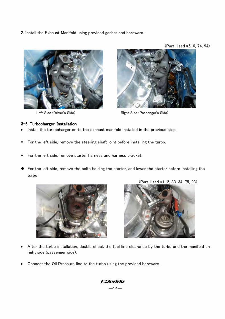
2. Install the Exhaust Manifold using provided gasket and hardware.
(Part Used #5, 6, 74, 94)
Left Side (Driver’s Side) Right Side (Passenger’s Side)
3333----6 6 6 6 Turbocharger InstallationTurbocharger InstallationTurbocharger InstallationTurbocharger Installation
• Install the turbocharger on to the exhaust manifold installed in the previous step.
* For the left side, remove the steering shaft joint before installing the turbo.
* For the left side, remove starter harness and harness bracket.
� For the left side, remove the bolts holding the starter, and lower the starter before installing the
turbo
(Part Used #1, 2, 33, 34, 75, 93)
• After the turbo installation, double check the fuel line clearance by the turbo and the manifold on
right side (passenger side).
• Connect the Oil Pressure line to the turbo using the provided hardware.
―15―
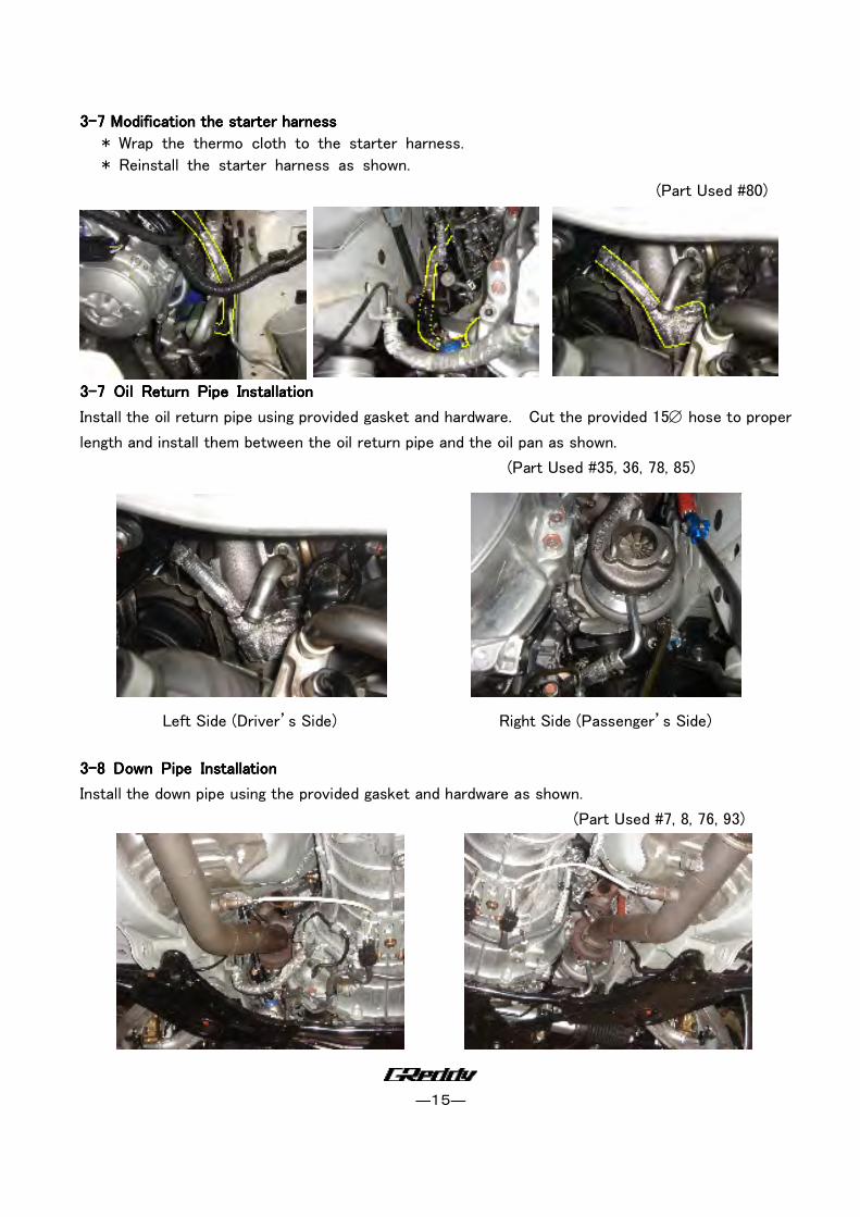
3333----7 7 7 7 Modification the Modification the Modification the Modification the starterstarterstarterstarter harness harness harness harness
* Wrap the thermo cloth to the starter harness.
* Reinstall the starter harness as shown.
(Part Used #80)
3333----7 7 7 7 Oil Return Pipe InstallationOil Return Pipe InstallationOil Return Pipe InstallationOil Return Pipe Installation
Install the oil return pipe using provided gasket and hardware. Cut the provided 15∅ hose to proper
length and install them between the oil return pipe and the oil pan as shown.
(Part Used #35, 36, 78, 85)
Left Side (Driver’s Side) Right Side (Passenger’s Side)
3333----8 8 8 8 Down Pipe InstallationDown Pipe InstallationDown Pipe InstallationDown Pipe Installation
Install the down pipe using the provided gasket and hardware as shown.
(Part Used #7, 8, 76, 93)
―16―
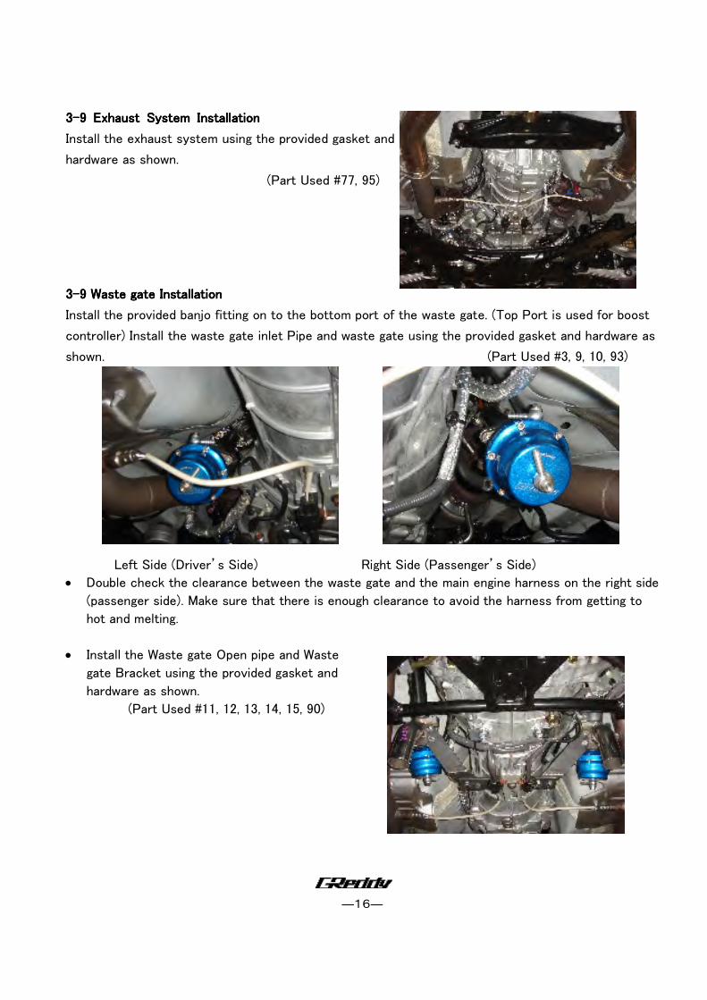
3333----9 9 9 9 ExhaExhaExhaExhaust System Installationust System Installationust System Installationust System Installation
Install the exhaust system using the provided gasket and
hardware as shown.
(Part Used #77, 95)
3333----9 9 9 9 WasteWasteWasteWaste gate Installationgate Installationgate Installationgate Installation
Install the provided banjo fitting on to the bottom port of the waste gate. (Top Port is used for boost
controller) Install the waste gate inlet Pipe and waste gate using the provided gasket and hardware as
shown. (Part Used #3, 9, 10, 93)
Left Side (Driver’s Side) Right Side (Passenger’s Side)
• Double check the clearance between the waste gate and the main engine harness on the right side
(passenger side). Make sure that there is enough clearance to avoid the harness from getting to
hot and melting.
• Install the Waste gate Open pipe and Waste
gate Bracket using the provided gasket and
hardware as shown.
(Part Used #11, 12, 13, 14, 15, 90)
―17―
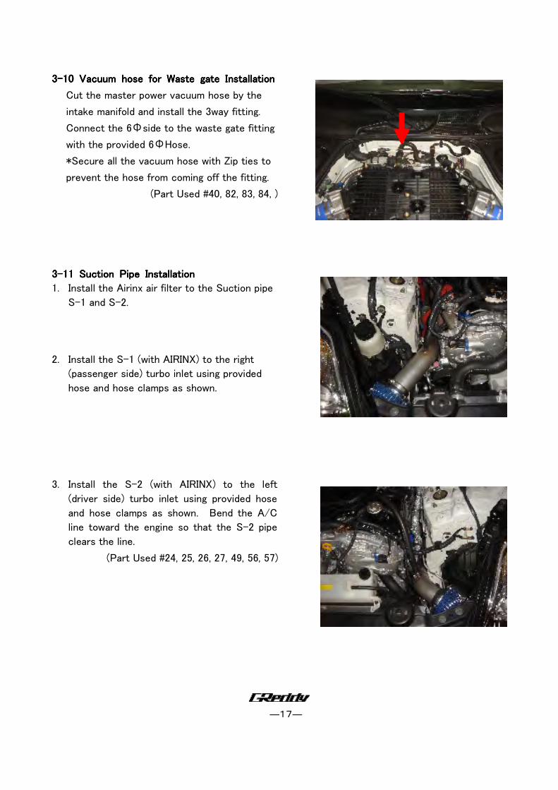
3333----10 10 10 10 Vacuum hose for WasteVacuum hose for WasteVacuum hose for WasteVacuum hose for Waste gate Installationgate Installationgate Installationgate Installation
Cut the master power vacuum hose by the
intake manifold and install the 3way fitting.
Connect the 6Φside to the waste gate fitting
with the provided 6ΦHose.
*Secure all the vacuum hose with Zip ties to
prevent the hose from coming off the fitting.
(Part Used #40, 82, 83, 84, )
3333----11 11 11 11 Suction Pipe InstallationSuction Pipe InstallationSuction Pipe InstallationSuction Pipe Installation
1. Install the Airinx air filter to the Suction pipe
S-1 and S-2.
2. Install the S-1 (with AIRINX) to the right
(passenger side) turbo inlet using provided
hose and hose clamps as shown.
3. Install the S-2 (with AIRINX) to the left
(driver side) turbo inlet using provided hose
and hose clamps as shown. Bend the A/C
line toward the engine so that the S-2 pipe
clears the line.
(Part Used #24, 25, 26, 27, 49, 56, 57)
―18―
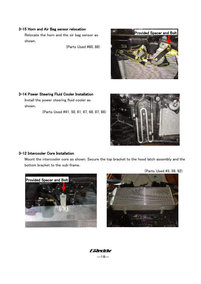
3333----15 15 15 15 Horn and Air Bag sensor relocationHorn and Air Bag sensor relocationHorn and Air Bag sensor relocationHorn and Air Bag sensor relocation
Relocate the horn and the sir bag sensor as
shown.
(Parts Used #60, 88)
3333----14 14 14 14 Power Steering Fluid Cooler InstallationPower Steering Fluid Cooler InstallationPower Steering Fluid Cooler InstallationPower Steering Fluid Cooler Installation
Install the power steering fluid cooler as
shown.
(Parts Used #41, 50, 61, 67, 68, 87, 88)
3333----12 Intercooler 12 Intercooler 12 Intercooler 12 Intercooler Core InstallationCore InstallationCore InstallationCore Installation
Mount the intercooler core as shown. Secure the top bracket to the hood latch assembly and the
bottom bracket to the sub-frame.
(Parts Used #3, 59, 92)
PPPProvidedrovidedrovidedrovided Spacer and Bolt Spacer and Bolt Spacer and Bolt Spacer and Bolt
PPPProvidedrovidedrovidedrovided Spacer and Bolt Spacer and Bolt Spacer and Bolt Spacer and Bolt
―19―
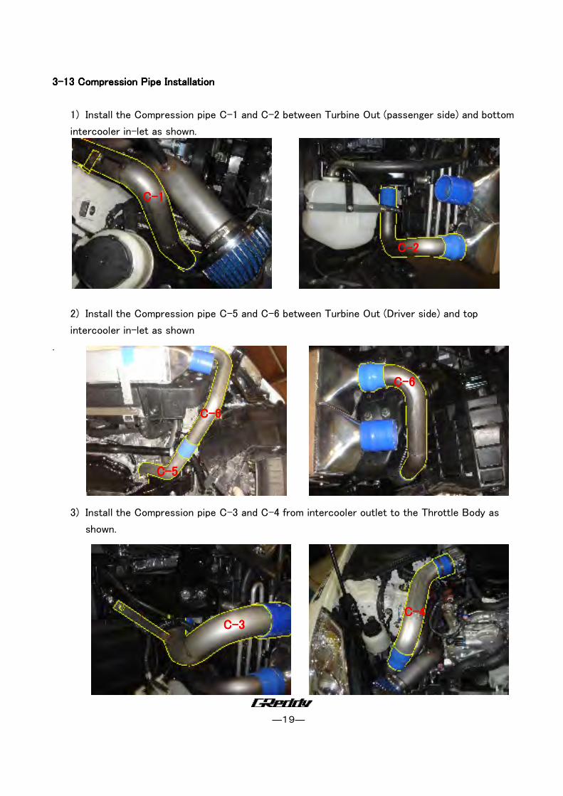
3333----13 Compression 13 Compression 13 Compression 13 Compression Pipe InstallationPipe InstallationPipe InstallationPipe Installation
1) Install the Compression pipe C-1 and C-2 between Turbine Out (passenger side) and bottom
intercooler in-let as shown.
2) Install the Compression pipe C-5 and C-6 between Turbine Out (Driver side) and top
intercooler in-let as shown
.
3) Install the Compression pipe C-3 and C-4 from intercooler outlet to the Throttle Body as
shown.
CCCC----1111
CCCC----2222
CCCC----5555
CCCC----6666
CCCC----6666
CCCC----3333 CCCC----4444
―20―
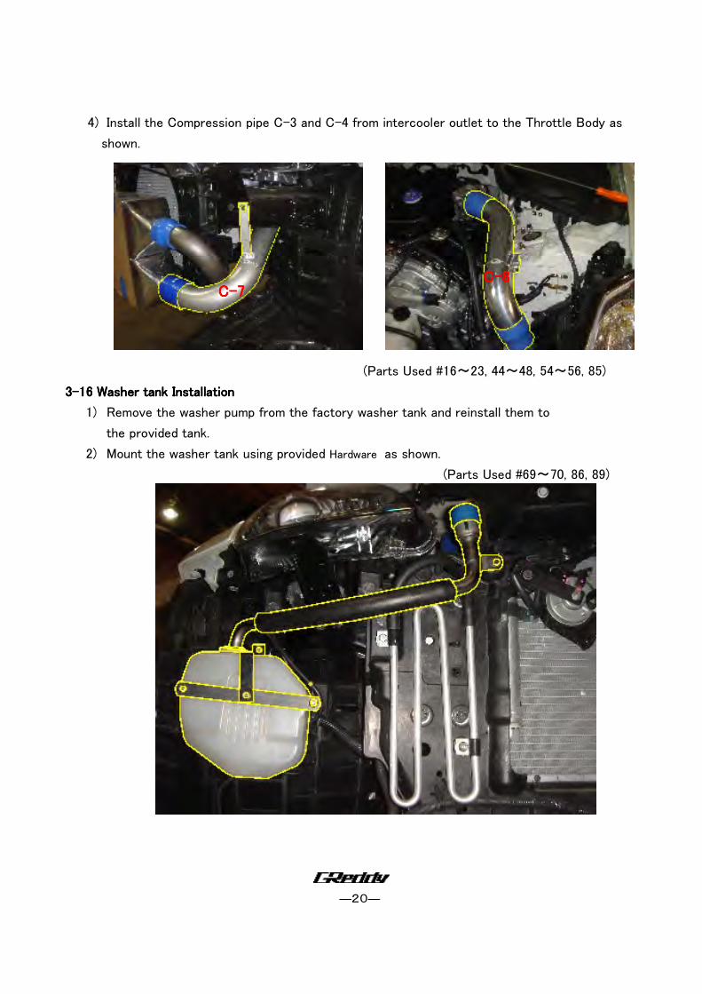
4) Install the Compression pipe C-3 and C-4 from intercooler outlet to the Throttle Body as
shown.
(Parts Used #16~23, 44~48, 54~56, 85)
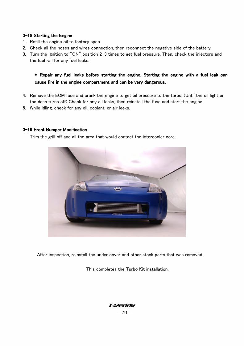
3333----16 16 16 16 Washer tank InstallationWasher tank InstallationWasher tank InstallationWasher tank Installation
1) Remove the washer pump from the factory washer tank and reinstall them to
the provided tank.
2) Mount the washer tank using provided Hardware as shown.
(Parts Used #69~70, 86, 89)
CCCC----7777 CCCC----8888
―21―
3333----18 18 18 18 Starting the EngineStarting the EngineStarting the EngineStarting the Engine
1. Refill the engine oil to factory spec.
2. Check all the hoses and wires connection, then reconnect the negative side of the battery.
3. Turn the ignition to “ON” position 2-3 times to get fuel pressure. Then, check the injectors and
the fuel rail for any fuel leaks.
* * * * Repair any fuel leaks before starting the engine. Starting the engine with a fuel leak can Repair any fuel leaks before starting the engine. Starting the engine with a fuel leak can Repair any fuel leaks before starting the engine. Starting the engine with a fuel leak can Repair any fuel leaks before starting the engine. Starting the engine with a fuel leak can
cause fire in the engine compartment and can be very dangerous. cause fire in the engine compartment and can be very dangerous. cause fire in the engine compartment and can be very dangerous. cause fire in the engine compartment and can be very dangerous.
4. Remove the ECM fuse and crank the engine to get oil pressure to the turbo. (Until the oil light on
the dash turns off) Check for any oil leaks, then reinstall the fuse and start the engine.
5. While idling, check for any oil, coolant, or air leeks.
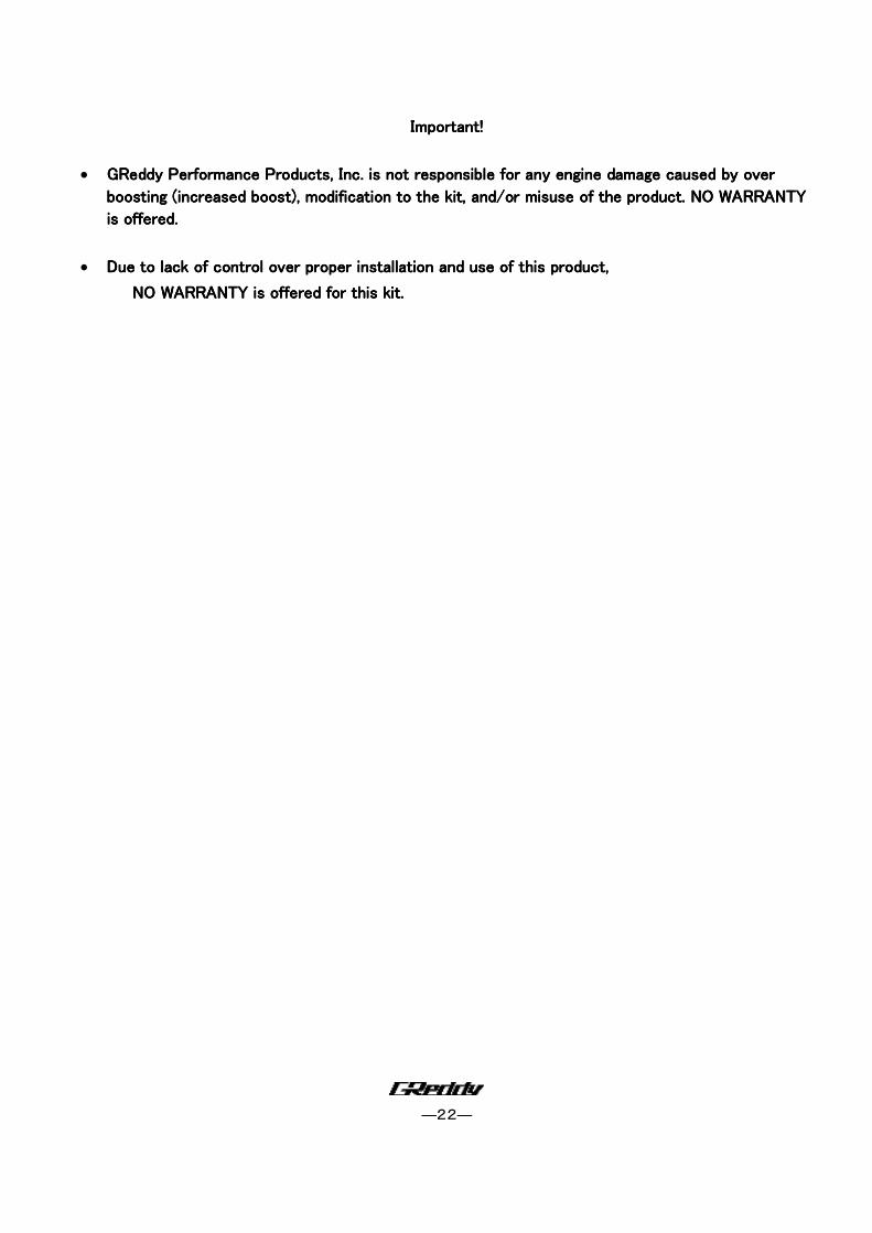
3333----19 19 19 19 Front Bumper ModiFront Bumper ModiFront Bumper ModiFront Bumper Modificationficationficationfication
Trim the grill off and all the area that would contact the intercooler core.
After inspection, reinstall the under cover and other stock parts that was removed.
This completes the Turbo Kit installation.
―22―
Important!Important!Important!Important!
• GReddy Performance PrGReddy Performance PrGReddy Performance PrGReddy Performance Products, Inc. is not responsible for any engine damage caused by over oducts, Inc. is not responsible for any engine damage caused by over oducts, Inc. is not responsible for any engine damage caused by over oducts, Inc. is not responsible for any engine damage caused by over
boosting (increased boost), modification to the kit, and/or misuse of the product. NO WARRANTY boosting (increased boost), modification to the kit, and/or misuse of the product. NO WARRANTY boosting (increased boost), modification to the kit, and/or misuse of the product. NO WARRANTY boosting (increased boost), modification to the kit, and/or misuse of the product. NO WARRANTY
is offered.is offered.is offered.is offered.
• Due to lack of control over proper installation and use of this product,Due to lack of control over proper installation and use of this product,Due to lack of control over proper installation and use of this product,Due to lack of control over proper installation and use of this product,
NO WARRANTY is offered for this kit.NO WARRANTY is offered for this kit.NO WARRANTY is offered for this kit.NO WARRANTY is offered for this kit.
Recommended