Aviation Safety Council
Taipei, Taiwan
GE235 Occurrence Investigation
Factual Data Collection
Group Report
Airworthiness Group
July 2, 2015
ASC-FRP-15-07-003

Intentionally Left Blank
3
Contents
I. Team Organization ................................................................................................. 5
II. History of Major Activities ..................................................................................... 6
III. Factual Description ............................................................................................ 9
1.3 Damage to aircraft ................................................................................................ 9
1.6 Aircraft information ............................................................................................. 9
1.6.1 Aircraft and engine basic information ........................................................ 9
1.6.2 Maintenance related information ............................................................. 10
1.6.3 Propellers system ..................................................................................... 10
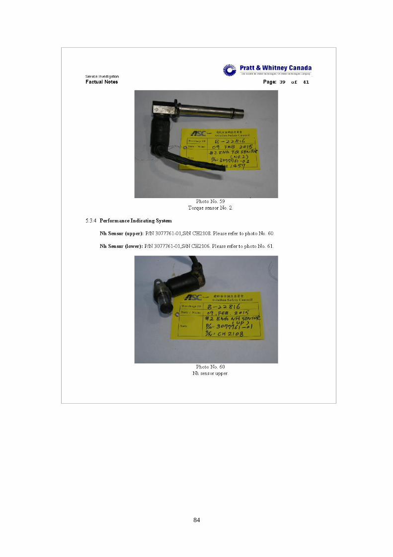
1.6.4 Engine torque sensing and indication ....................................................... 15
1.12 Wreckage and impact information ................................................................... 16
1.12.1 Recovery of aircraft wreckage ............................................................... 17
1.12.2 Wreckage transfer and temporary storage .............................................. 21
1.16 Test and research .............................................................................................. 22
1.16.1 Aircraft structure examination ............................................................... 22
1.16.2 Engines examination .............................................................................. 22
1.16.2.1 No.1 engine ........................................................................................ 23
1.16.2.2 No.2 engine ........................................................................................ 24
1.16.3 Components test and examination .......................................................... 25
1.16.3.1 AFUs tests .......................................................................................... 25
1.16.3.2 MFCs NVM data download ................................................................ 32
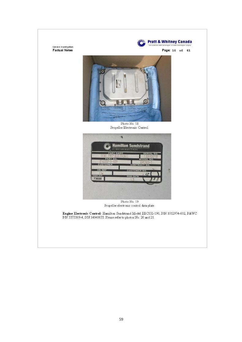
1.16.3.3 PECs and EECs data download ........................................................... 34
1.16.3.4 Harnesses ........................................................................................... 35
1.16.3.5 Accessories tests ................................................................................. 37
1.18 Additional information ..................................................................................... 38
1.18.1 Interview summaries .............................................................................. 38
1.18.1.1 Assistant manager of maintenance division ......................................... 38
4
1.18.1.2 Maintenance personnel stationed in Kinmen airport ......................... 39
1.18.1.3 Maintenance personnel stationed in Songshan airport ......................... 40
1.18.2 Abnormal engine torque related events/information ............................... 41
1.18.2.1 Chronology of TNA ATR72 aircraft abnormal engine torque related
events/information ........................................................................................... 41
1.18.2.2 Related Service Information issued by P&WC .................................... 42
1.18.3 Wreckage and LRU database ................................................................. 43
IV. Appendix .......................................................................................................... 45
Appendix 1. ATR-72 Reg. B-22816 Accident Investigation, Engine Inspection
Factual Notes ................................................................................................... 46
Appendix 2. Summary of Field Notes, Examination of Autofeathering ............. 87
Appendix 3. Technical document, Cable TQ sensor – AFU engine 1 & 2, X-Ray
and macroscopic examination report ................................................................ 88
Appendix 4. Test results of torque and speed sensors ....................................... 98
V. Attachment.......................................................................................................... 100
5
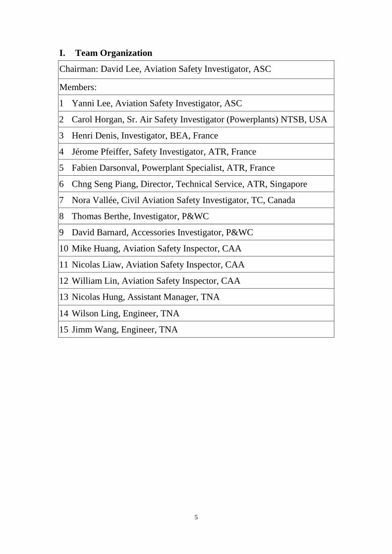
I. Team Organization
Chairman: David Lee, Aviation Safety Investigator, ASC
Members:
1 Yanni Lee, Aviation Safety Investigator, ASC
2 Carol Horgan, Sr. Air Safety Investigator (Powerplants) NTSB, USA
3 Henri Denis, Investigator, BEA, France
4 Jérome Pfeiffer, Safety Investigator, ATR, France
5 Fabien Darsonval, Powerplant Specialist, ATR, France
6 Chng Seng Piang, Director, Technical Service, ATR, Singapore
7 Nora Vallée, Civil Aviation Safety Investigator, TC, Canada
8 Thomas Berthe, Investigator, P&WC
9 David Barnard, Accessories Investigator, P&WC
10 Mike Huang, Aviation Safety Inspector, CAA
11 Nicolas Liaw, Aviation Safety Inspector, CAA
12 William Lin, Aviation Safety Inspector, CAA
13 Nicolas Hung, Assistant Manager, TNA
14 Wilson Ling, Engineer, TNA
15 Jimm Wang, Engineer, TNA
6
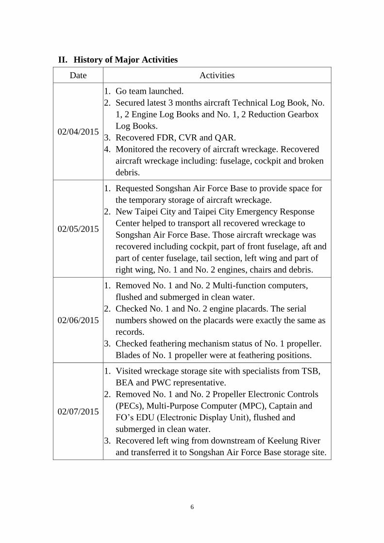
II. History of Major Activities
Date Activities
02/04/2015
1. Go team launched.
2. Secured latest 3 months aircraft Technical Log Book, No.
1, 2 Engine Log Books and No. 1, 2 Reduction Gearbox
Log Books.
3. Recovered FDR, CVR and QAR.
4. Monitored the recovery of aircraft wreckage. Recovered
aircraft wreckage including: fuselage, cockpit and broken
debris.
02/05/2015
1. Requested Songshan Air Force Base to provide space for
the temporary storage of aircraft wreckage.
2. New Taipei City and Taipei City Emergency Response
Center helped to transport all recovered wreckage to
Songshan Air Force Base. Those aircraft wreckage was
recovered including cockpit, part of front fuselage, aft and
part of center fuselage, tail section, left wing and part of
right wing, No. 1 and No. 2 engines, chairs and debris.
02/06/2015
1. Removed No. 1 and No. 2 Multi-function computers,
flushed and submerged in clean water.
2. Checked No. 1 and No. 2 engine placards. The serial
numbers showed on the placards were exactly the same as
records.
3. Checked feathering mechanism status of No. 1 propeller.
Blades of No. 1 propeller were at feathering positions.
02/07/2015
1. Visited wreckage storage site with specialists from TSB,
BEA and PWC representative.
2. Removed No. 1 and No. 2 Propeller Electronic Controls
(PECs), Multi-Purpose Computer (MPC), Captain and
FO’s EDU (Electronic Display Unit), flushed and
submerged in clean water.
3. Recovered left wing from downstream of Keelung River
and transferred it to Songshan Air Force Base storage site.

7
02/08/2015
1. Removed Captain and FO’s PFD, ND and center DU,
ATPCS control panel, 2 CMS computers, flushed and
submerged in clean water.
2. Checked No. 1, 2 engines with bore scope, all engine
turbine sections showed normal conditions.
3. Checked No. 1 engine torque sensors of No. 1, 2 engines,
resistance of sensor connectors were all within specs. AFU
electrical harness continuity checks were all passed.
02/09/2015
1. Witnessed by BEA, ATR, TC, TSB and CAA personnel to
remove parts from No. 1, 2 engines for further
testing/inspection:
a. 2 Engine Electronic Controls (EEC)
b. 2 Data Collection Units (DCU)
c. 2 Auto Feather Units (AFU)
d. 2 Propeller Interface Units (PIU)
e. 2 Core Avionic Cabinets (CAC)
f. 2 AFU electrical harnesses
g. 4 torque sensors
h. 8 speed sensors (4 Nh, 2 Nl, 2 Np)
i. 2 fire handles
2. Measure stick pusher actuator length; the actuator was at
retracted position.
02/10/2015 Examined 7 pieces of aircraft wreckage structures. All broken
structures were due to overload and post impact damages.
02/13/2015 Sent 22/25 recovered components to TSB/BEA for inspection
and / or test. TSB/BEA received those items on Feb. 19, 2015.
02/25/2015 Removed 2 Propeller Valve Modules (PVM) from No. 1, 2
engines and stored in ASC laboratory.
8
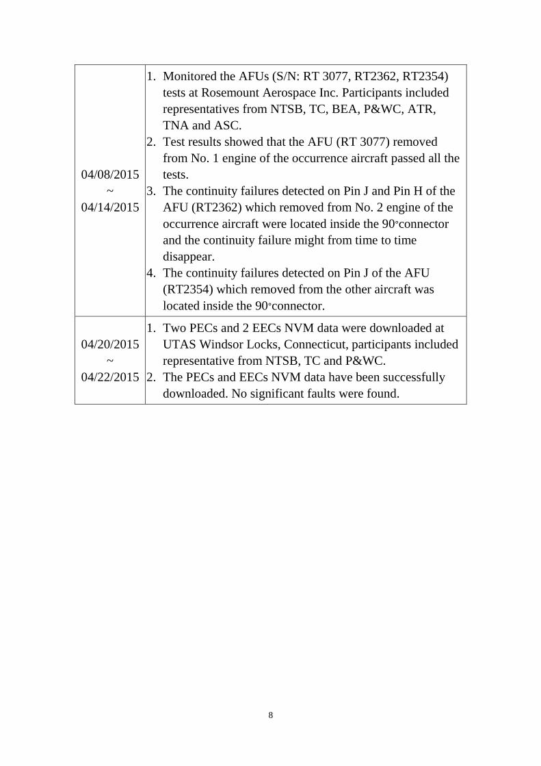
04/08/2015
~
04/14/2015
1. Monitored the AFUs (S/N: RT 3077, RT2362, RT2354)
tests at Rosemount Aerospace Inc. Participants included
representatives from NTSB, TC, BEA, P&WC, ATR,
TNA and ASC.
2. Test results showed that the AFU (RT 3077) removed
from No. 1 engine of the occurrence aircraft passed all the
tests.
3. The continuity failures detected on Pin J and Pin H of the
AFU (RT2362) which removed from No. 2 engine of the
occurrence aircraft were located inside the 90∘connector
and the continuity failure might from time to time
disappear.
4. The continuity failures detected on Pin J of the AFU
(RT2354) which removed from the other aircraft was
located inside the 90∘connector.
04/20/2015
~
04/22/2015
1. Two PECs and 2 EECs NVM data were downloaded at
UTAS Windsor Locks, Connecticut, participants included
representative from NTSB, TC and P&WC.
2. The PECs and EECs NVM data have been successfully
downloaded. No significant faults were found.

9
III. Factual Description
1.3 Damage to aircraft
The aircraft was destroyed.
1.6 Aircraft information
1.6.1 Aircraft and engine basic information
Basic information of the occurrence aircraft is shown in Table 1.6-1
Table 1.6-1 Aircraft basic information
Aircraft basic information (statistics date: February 04, 2015)
Nationality Taiwan, R.O.C.
Aircraft registration number B-22816
Manufacturer Avions de Transport Régional
Aircraft model ATR72-212A
Aircraft serial number 1141
Manufactured date April 14, 2014
Delivery date April 14, 2014
Owner TransAsia Airways
Operator TransAsia Airways
Number of certificate of
registration 103-1271
Certificate of airworthiness,
validity date March 31, 2015
Total time (hours) 1627:05
Total cycles 2356
Last check, date A4 CHECK / January 26, 2015
Time / cycles since last check 44:50 / 64
Basic information of the two Pratt & Whitney Canada engines is
shown in Table 1.6-2
10
Table 1.6-2 Engine basic information
Engine basic information (statistics date: February 04, 2015)
Number/position No. 1/ Left No. 2/ Right
Manufacturer PWC PWC
Model PW127M PW127M
Serial number ED0913 ED0814
Manufacture date May 09, 2014 November 19, 2013
Installation date August 16, 2014 February 07, 2014
Time since installation
(hours) 829:31 1627:05
Cycle since installation 1240 2356
Last check, date A4 CHECK /
January 26, 2015
A4 CHECK /
January 26, 2015
Time / cycles since last
check 44:50 / 64 44:50 / 64
1.6.2 Maintenance related information
A review of maintenance record before the occurrence flight showed
that there was no defects report or Minimum Equipment List (MEL) item
of the occurrence flight when the aircraft was dispatched from Songshan
airport to Kinmen airport. The Technical Log Books (TLBs) from aircraft
delivery date to the occurrence date, the pre-flight check, daily check,
transit check records of the last 6 months and the last periodic check (A4
check) records before the occurrence were reviewed. There was no defect
report related to autofeather of the No.2 engine.
The Deferred Defect (DD) records, status of Airworthiness Directive
(AD) and Service Bulletin (SB) of the occurrence aircraft were also
reviewed. The control of DD records of the occurrence aircraft were in
compliance with CAA regulation and no DD item related to autofeather
of the No.2 engine was found. The review showed that the occurrence
aircraft was in compliance with all applicable AD and SB.
1.6.3 Propellers system
The occurrence aircraft was equipped with HAMILTON
STANDARD 568F-1 propellers. The propeller is of the variable pitch

11
type, hydromechanically controlled, and can be placed in reverse or
feathering configurations. According to the Aircraft Maintenance Manual,
Description / Operation (AMM D/O) (Revision number = 38, Revision
date = Dec 01/14), the propeller’s operating modes include propeller in a
governing speed mode, synchrophasing, propeller in a governing pitch
mode and feathering / unfeathering modes.
Feathering can be performed:
Manually, by the condition lever in case of engine failure
Automatically, in case of torque decrease at take-off on one
engine
Manually, by the fire handle in case of engine fire
Manually, during maintenance operations
When the condition lever is moved past the safety trigger of FTR
position, micro switch 5KF (6KF) and 54KF (55KF) are activated which
enables the activation of the feather pump, energization of the feather
solenoid and indication to the Propeller Electronic Control (PEC) to
command pitch increase toward feather.
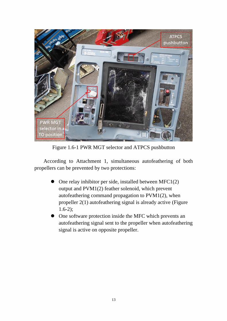
The Automatic Takeoff Power Control System (ATPCS) is
operational if it is armed prior to take-off. Arming of the system is
performed when all the following conditions are simultaneously met:
Power Management (PWR MGT) selector switch is placed in
TO (Take-Off) (Figure 1.6-1) position
ATPCS (pushbutton(Figure 1.6-1) switch is pressed in
Torques of engines 1 and 2 are higher than 46.2% which
corresponds to 5,558 ft.lb
both power levers are above 55 degrees MFCU (Mechanical
Fuel Control Unit) (equivalent to 49 degrees of power lever
angle)
When the ATPCS is armed, ARM legend of ATPCS comes on.
When the system is armed, a torque lower than 18.5% on one engine
causes uptrim of the other engine. The uptrim causes the valid engine
increasing its power from TO to RTO (Reserve Take-Off), and 2.15
second later, the propeller of the faulty engine is automatically feathered

12
by activation of the Propeller Valve Module (PVM) solenoid and increase
of the pitch by the PEC. From then automatic feathering of the valid
engine is prohibited to ensure both engines are not feathered at the same
time.
According to the BEA provided GE235 Answer to Action Log
Revision #4 (Attachment 1), once the ATPCS sequence has been
triggered, autofeathering of the failed engine can be aborted during the
2.15 seconds if at least one of the following conditions is true:
PWR MGT selector switch is moved out of TO position
ATPCS push button is released off
At least one of the power levers is retarded below 55 degrees
MFCU (equivalent to 49 degrees of power lever angle)
Torque of the engine detected failed increases above 2,229 ft.
lb threshold
Torque of the sane engine drops below 5,558 ft. lb threshold.
The autofeathering and UPTRIM system is disarmed after 2.15
seconds delay when any of the arming conditions is cancelled. The
cancellation can only result from one of the following conditions:
PWR MGT selector other than TO
ATPCS push button set to OFF
Both power lever retarded below 55 degrees MFCU
(equivalent to 49 degrees of power lever angle).
When the ATPCS is not selected at take-off, an aural warning is
triggered and warning lights come on if the autofeathering is not selected
during TO CONFIG test.
13
Figure 1.6-1 PWR MGT selector and ATPCS pushbutton
According to Attachment 1, simultaneous autofeathering of both
propellers can be prevented by two protections:
One relay inhibitor per side, installed between MFC1(2)
output and PVM1(2) feather solenoid, which prevent
autofeathering command propagation to PVM1(2), when
propeller 2(1) autofeathering signal is already active (Figure
1.6-2);
One software protection inside the MFC which prevents an
autofeathering signal sent to the propeller when autofeathering
signal is active on opposite propeller.

14
Figure 1.6-2 Functions of the ATPCS system
When the fire handle is pulled, feathering is performed identical to
that of the automatic feathering system. Upper two photos of Figure 1.6-3
show that both safety wires of No. 1 and No. 2 fire handles are secured in
place. Lower two photos of Figure 1.6-3 show the pointers of two fire
bottle pressure gages are in the green ranges.
Figure 1.6-3 No. 1, 2 fire handles and fire bottles

15
1.6.4 Engine torque sensing and indication
According to the AMM D/O, torque is one of engine parameters
associated with power. Each engine contains two torque sensors which
located on the reduction gearbox casing at 4 (No. 2) and 8 (No. 1) o’clock
approximately when looking forward. Torque sensors are used to measure
the torque produced by the engine.
As shown in Figure 1.6-4, the signal sensed by the No. 1 and No. 2
sensors is transmitted to the Auto Feather Unit (AFU) and the Electronic
Engine Control (EEC) respectively, where it is converted into engine
torque indications. The AFU and EEC transmit the data to the Core
Avionic Cabinet 1 (CAC1) and CAC2. The CAC is provided with the
5VDC reference voltage and the signal from the AFU, which are then
routed to Display Unit (DU) through ARINC 429 and displays the
TORQUE value in analog form. The indication in the digital form is
provided in ARINC 429 message from the EEC to DU. The torque value
in digital form is also transmitted to the Multi-Purpose Computer (MPC),
which is then stored in the Solid State Flight Data Recorder (SSFDR)
through ARINC 429.
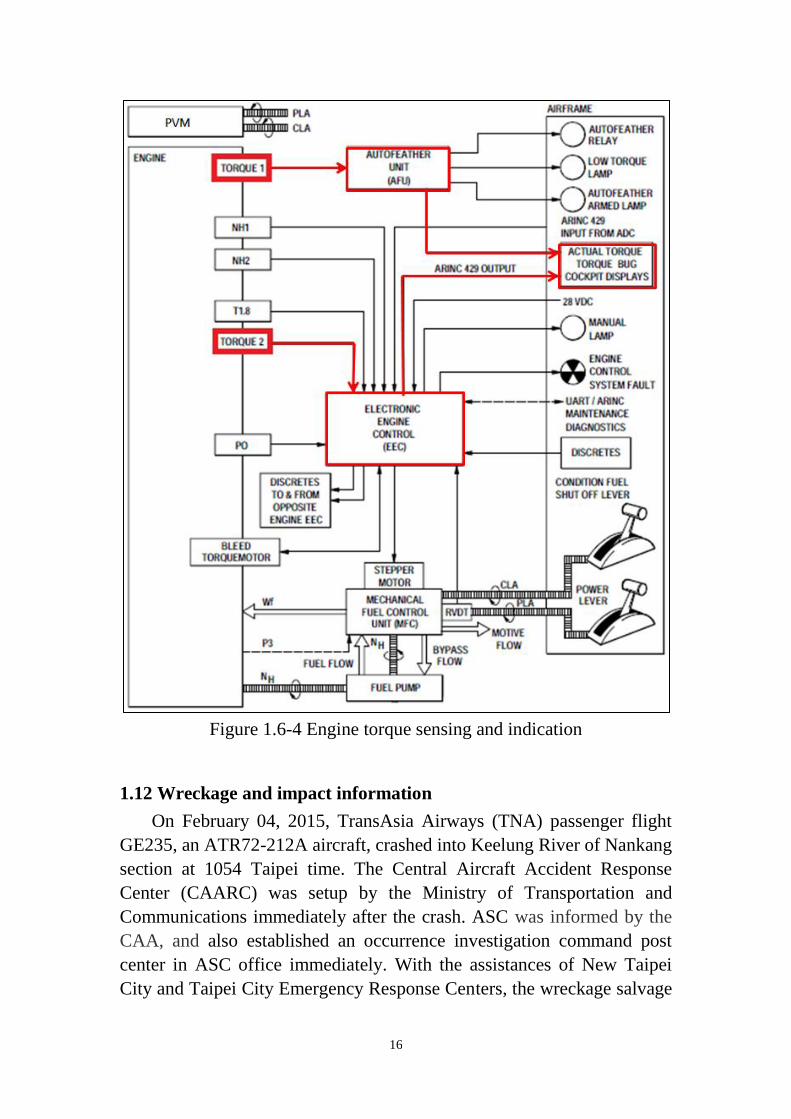
16
Figure 1.6-4 Engine torque sensing and indication
1.12 Wreckage and impact information
On February 04, 2015, TransAsia Airways (TNA) passenger flight
GE235, an ATR72-212A aircraft, crashed into Keelung River of Nankang
section at 1054 Taipei time. The Central Aircraft Accident Response
Center (CAARC) was setup by the Ministry of Transportation and
Communications immediately after the crash. ASC was informed by the
CAA, and also established an occurrence investigation command post
center in ASC office immediately. With the assistances of New Taipei
City and Taipei City Emergency Response Centers, the wreckage salvage
17
and transportation to storage site operations were finished in one and a
half days. This section states recovery of aircraft wreckage, wreckage
transfer and wreckage temporary storage (Attachment 2).
1.12.1 Recovery of aircraft wreckage
Upon receiving the occurrence notification, ASC launched go team to
the occurrence site right after a pre-investigation meeting. The members
of go team included Investigator-in-charge (IIC) and investigators in
flight operation, maintenance, flight recorders, survival factors and
wreckage recovery.
The aircraft wreckage was broken into the cockpit and middle/aft
fuselage two major portions with its nose immersed in the mud of
riverbed. A floating bridge and three heavy lift vehicles were deployed by
the Army Engineering Corps to facilitate the rescue of the victims and
recovery of the aircraft wreckage. While the search and rescue operations
were continuously going, the salvage operation of aircraft wreckage was
commenced in the late afternoon of the occurrence day. The FDR and
CVR of the aircraft were found at 1605 local time and had been delivered
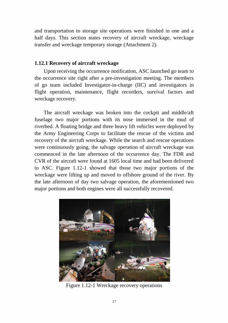
to ASC. Figure 1.12-1 showed that those two major portions of the
wreckage were lifting up and moved to offshore ground of the river. By
the late afternoon of day two salvage operation, the aforementioned two
major portions and both engines were all successfully recovered.
Figure 1.12-1 Wreckage recovery operations
18
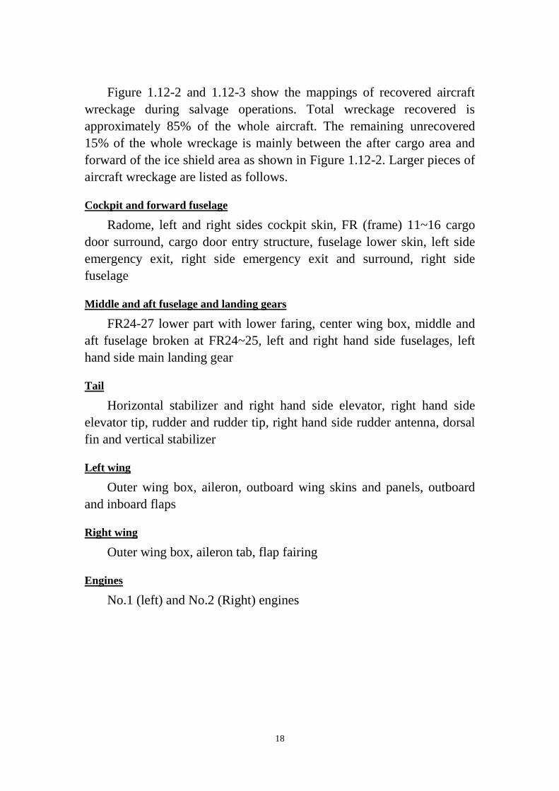
Figure 1.12-2 and 1.12-3 show the mappings of recovered aircraft
wreckage during salvage operations. Total wreckage recovered is
approximately 85% of the whole aircraft. The remaining unrecovered
15% of the whole wreckage is mainly between the after cargo area and
forward of the ice shield area as shown in Figure 1.12-2. Larger pieces of
aircraft wreckage are listed as follows.
Cockpit and forward fuselage
Radome, left and right sides cockpit skin, FR (frame) 11~16 cargo
door surround, cargo door entry structure, fuselage lower skin, left side
emergency exit, right side emergency exit and surround, right side
fuselage
Middle and aft fuselage and landing gears
FR24-27 lower part with lower faring, center wing box, middle and
aft fuselage broken at FR24~25, left and right hand side fuselages, left
hand side main landing gear
Tail
Horizontal stabilizer and right hand side elevator, right hand side
elevator tip, rudder and rudder tip, right hand side rudder antenna, dorsal
fin and vertical stabilizer
Left wing
Outer wing box, aileron, outboard wing skins and panels, outboard
and inboard flaps
Right wing
Outer wing box, aileron tab, flap fairing
Engines
No.1 (left) and No.2 (Right) engines
19
Figure 1.12-2 Recovered aircraft wreckages (1)

20
Figure 1.12-3 Recovered aircraft wreckages (2)

21
1.12.2 Wreckage transfer and temporary storage
With the support of the Ministry of National Defense (MND), the
recovered aircraft wreckage was transported to the Songshan Air Force
Base (SAFB) for temporary storage and subsequent inspections. With the
assistances of New Taipei City and Taipei City Emergency Response
Centers, all the aircraft wreckages were loaded into five trucks and
transported to the SAFB as shown in Figure 1.12-4. The operation of
aircraft wreckage transfer was finished in the late night of February 05,
the second day after the occurrence.
Figure 1.12-4 Wreckage transferring to storage site by trucks
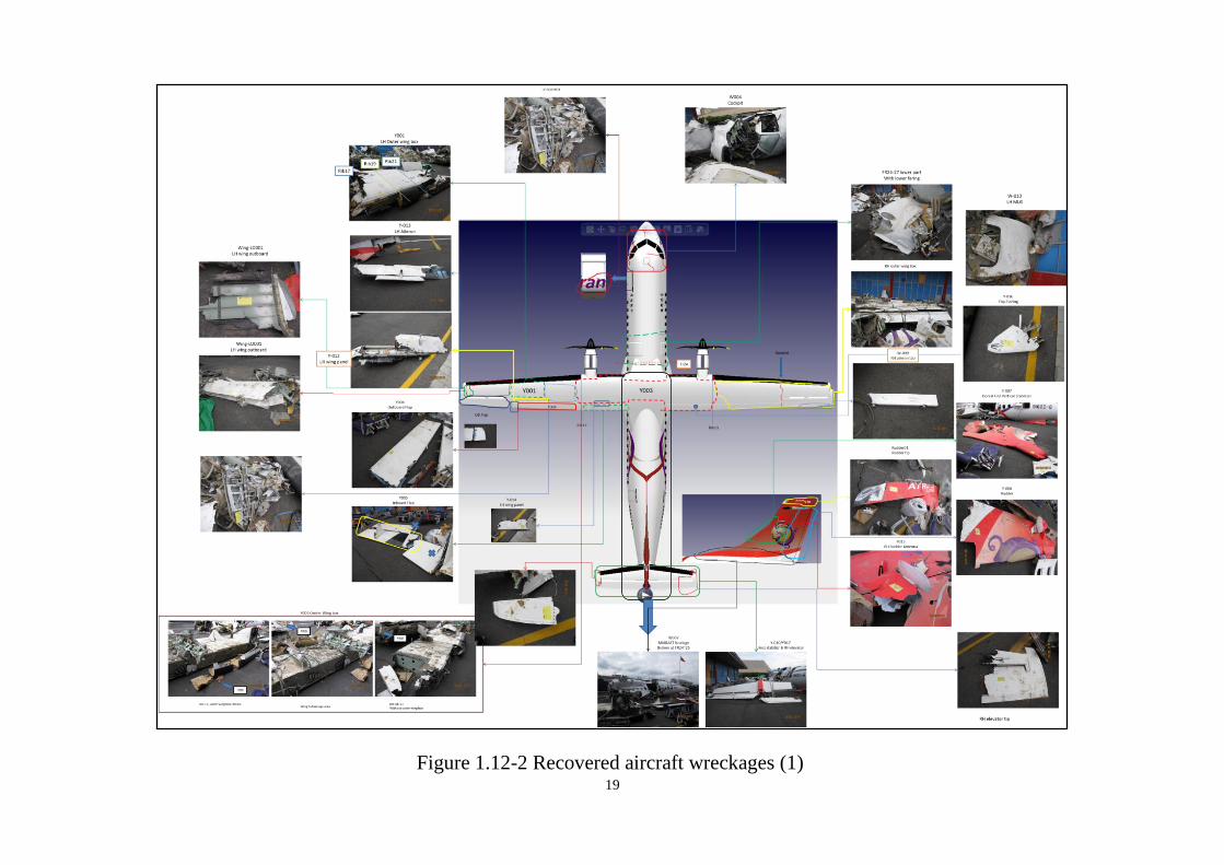
Figure 1.12-5 shows the aircraft cockpit portion was lifted and moved
to the wreckage storage site. The locations of wreckage were arranged as
two dimensions reconstruction of whole fuselage. The aircraft emergency
locator transmitter (ELT) was deactivated on February 06 after being
notified by Songshan airport.
22
Figure 1.12-5 Temporary wreckage storage site
1.16 Test and research
1.16.1 Aircraft structure examination
The examination of aircraft structure was conducted on February 10,
2015 at the wreckage storage site in SAFB. The examination was finished
with joint efforts of ASC, CAA, and TNA structure engineers. Totally 7
aircraft structural pieces were examined. Those fractured surfaces of
structural pieces all showed overload and post impact damages. The
results of examination were fed into the wreckage structure database
which was compiled by ASC during wreckage recovery operation.
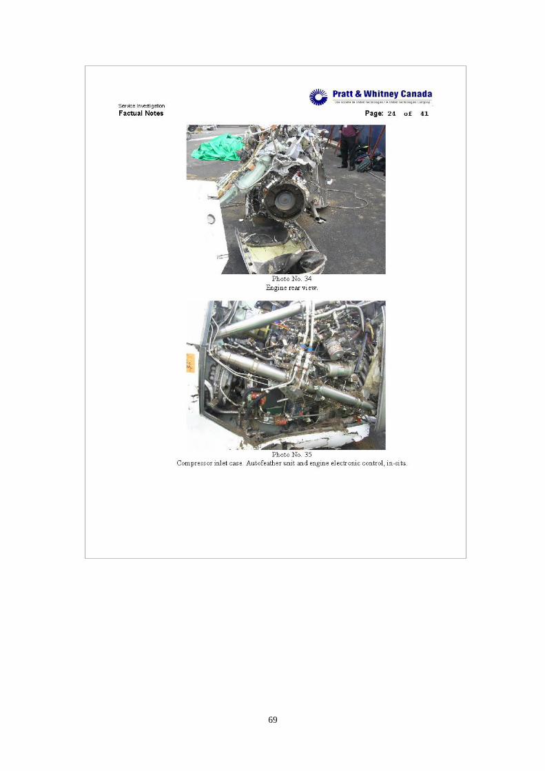
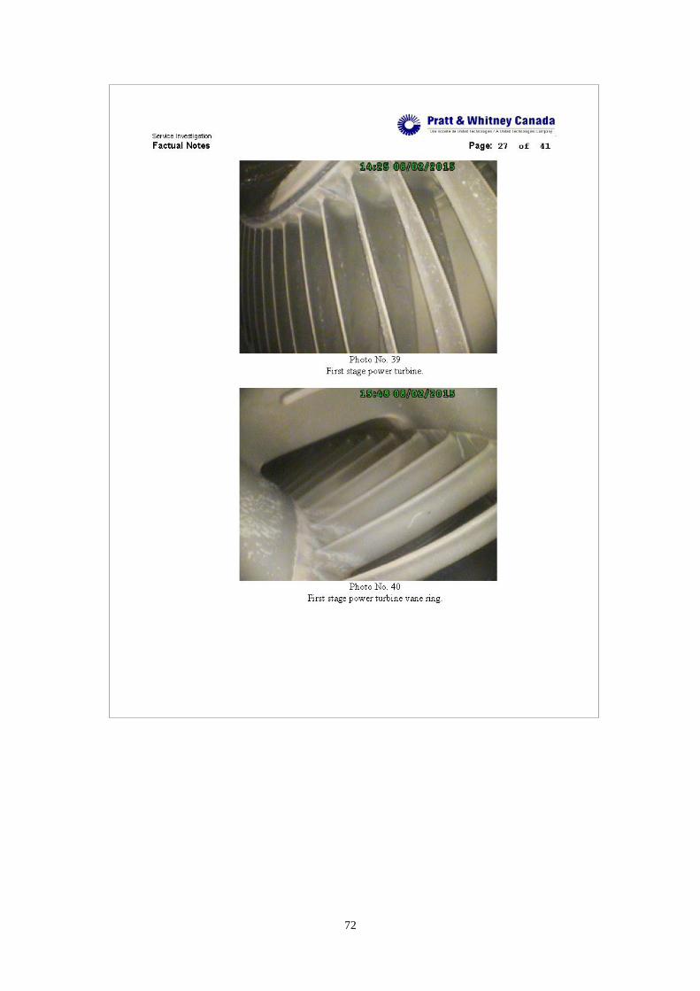
1.16.2 Engines examination
The examination of engines was conducted on February 7-9, 2015 at
the wreckage storage site in SAFB. Representatives from the following
organizations participated in the examination: Transportation Safety
Board (TSB) Canada, Transport Canada (TC), ATR, P&WC, CAA, TNA
23
and ASC. After the examination, the P&WC service investigation
provided the factual notes (Appendix 1).
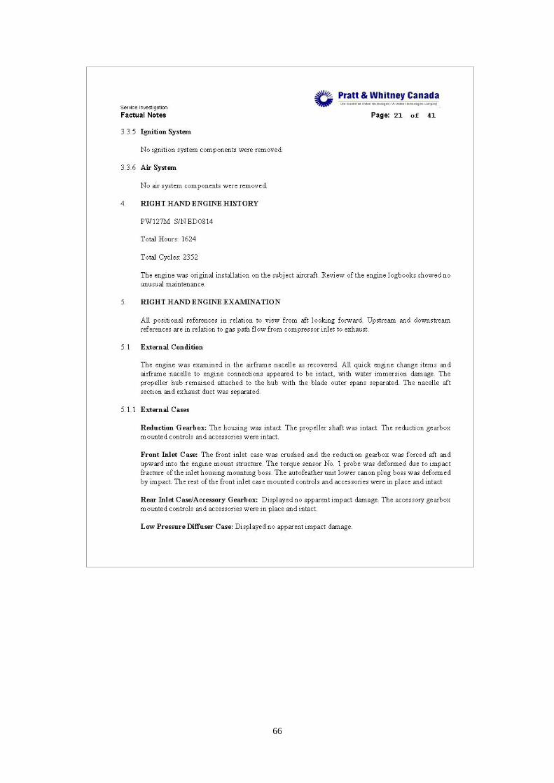
1.16.2.1 No.1 engine
The No. 1 engine is a P&WC Model PW127M, serial number
ED0913, total hours 829:31 and total cycles 1240. The engine was
installed on the occurrence aircraft following aircraft delivery due to a
low oil pressure event with the original installed engine. Review of the
engine logbook and reduction gearbox logbook showed no unusual
maintenance.
The No. 1 engine was examined in the airframe nacelle as recovered.
The external case inspection showed all quick engine change items and
airframe nacelle to engine connections appeared to be intact, with water
immersion damage. The propeller blade remained attached to the hub
with the blade outer spans separated.
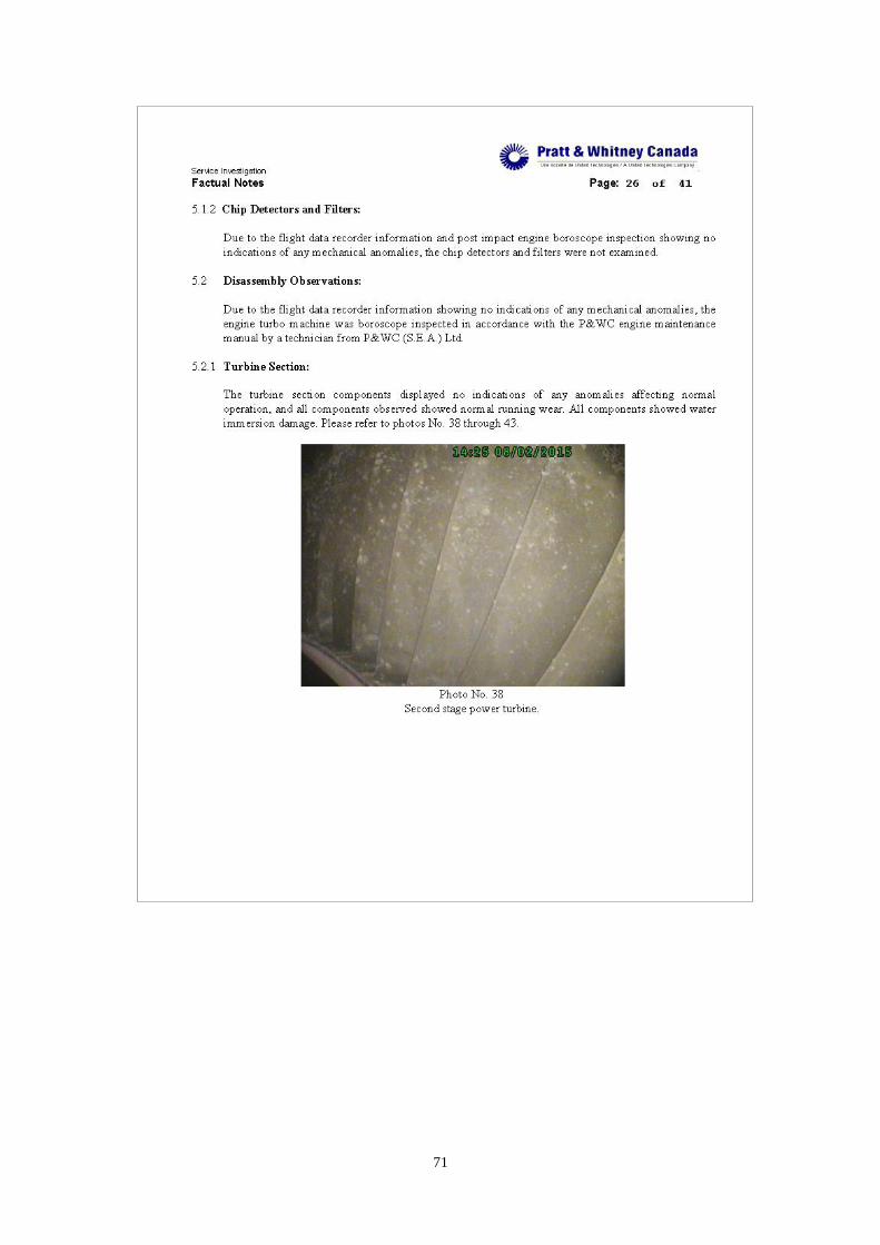
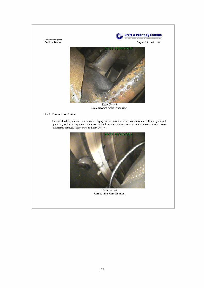
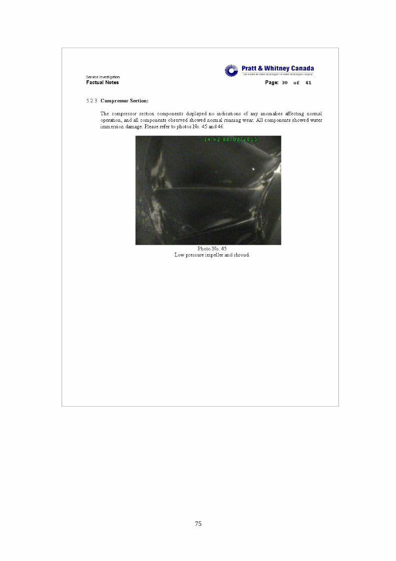
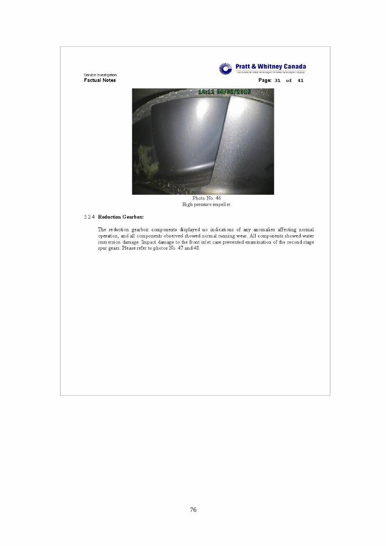
The engine turbo machine was borescope inspected in accordance
with the PW127 engine maintenance manual. The turbine section
components, combustion section components, compressor section
components and reduction gearbox components all displayed no
indications of any anomalies affecting normal operation, and all
components observed showed normal running wear. All components
showed immersion damage.
Some control and accessory components of No. 1 engine were
removed and shipped to TSB Canada for routing to their respective
vendors for investigation and analysis under the oversight of National
Transportation Safety Board (NTSB), Transport Canada (TC), BEA,
P&WC, ATR, UTAS and ASC. The removed components are as
following: Propeller Electronic Control (PEC), Engine Electronic Control
(EEC), Auto Feather Unit (AFU), Data Collection Unit (DCU), Torque
Sensor No. 1 and No. 2, upper and lower Nh Sensors, Nl sensor and Np
sensor.
24
1.16.2.2 No.2 engine
The No. 2 engine is a P&WC Model PW127M, serial number
ED0814, total hours 1627:05 and total cycles 2356. The engine was an
original installation on the occurrence aircraft. Review of the engine
logbook and reduction gearbox logbook showed no unusual maintenance.
The No. 2 engine was examined in the airframe nacelle as recovered.
The external case inspection showed all quick engine change items and
airframe nacelle to engine connections appeared to be intact, with water
immersion damage. The propeller blade remained attached to the hub
with the blade outer spans separated. The nacelle aft section and exhaust
duct were separated.
The engine turbo machine was borescope inspected in accordance
with the PW127 engine maintenance manual. The turbine section
components, combustion section components, compressor section
components and reduction gearbox components all displayed no
indications of any anomalies affecting normal operation, and all
components observed showed normal running wear. All components
showed immersion damage.
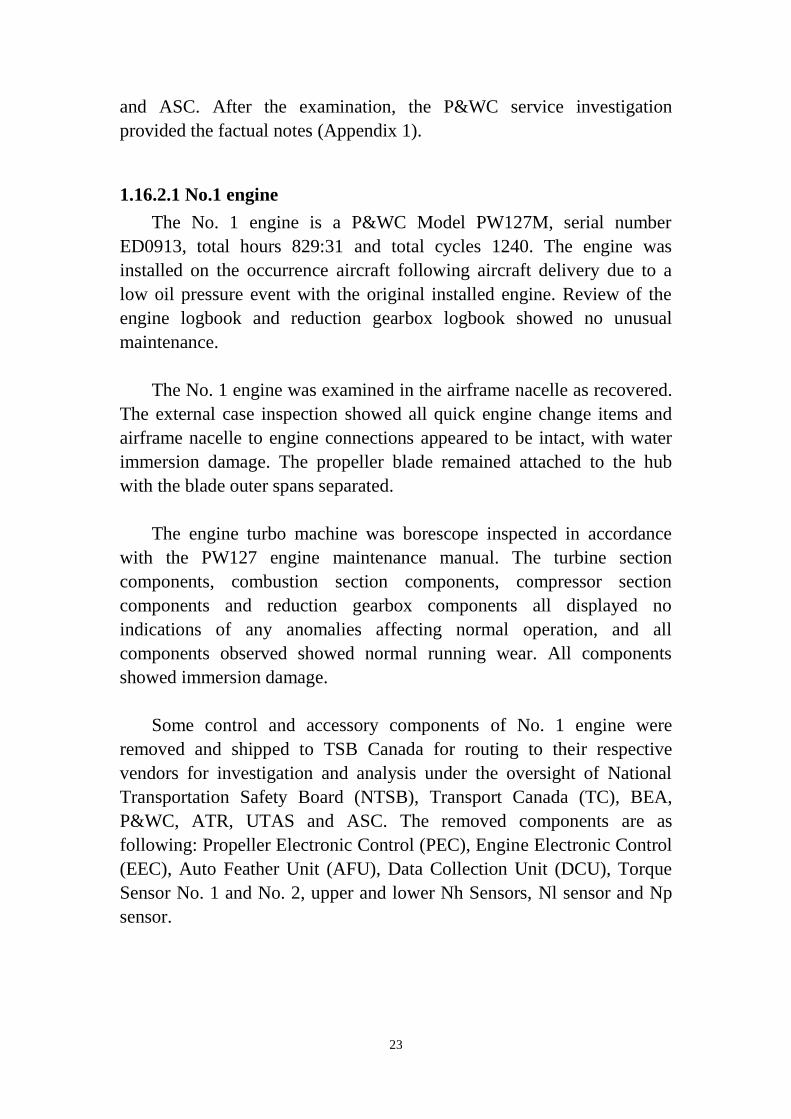
To troubleshoot the fault of uncommanded autofeather, the continuity
check was done on the AFU harness which connecting the AFU and No.1
torque sensor. According to the PW127 engine maintenance manual, all
the results are within limits (see Table 1.16-1 and Figure 1.16-1). Upon
removal of the harness plugs for the continuity check, both the torque
probe and AFU plugs showed slight water ingress to plug retaining collar.
The connector pin seats appeared to be dry.
Table 1.16-1 Continuity check of No. 2 AFU electrical circuit
Point-A Point-B expected result
J6 pin A J6 pin B 553-589 ohms 575 ohms
P16 pin H P6 pin A 0-0.5 ohms 0 ohm
P16 pin J P6 pin B 0-0.5 ohms 0 ohm
Insulation resistance (with reference to ground) of torque sensor No. 1 > 2
Mohms
25
Figure 1.16-1 Continuity check of No. 2 AFU electrical circuit
Some control and accessory components of No. 2 engine were
removed and shipped to TSB Canada for routing to their respective
vendors for investigation and analysis under the oversight of NTSB, TC,
BEA, P&WC, ATR, UTAS and ASC. The removed components are as
following: PEC, EEC, AFU, DCU, Torque Sensor No. 1 and No. 2, upper
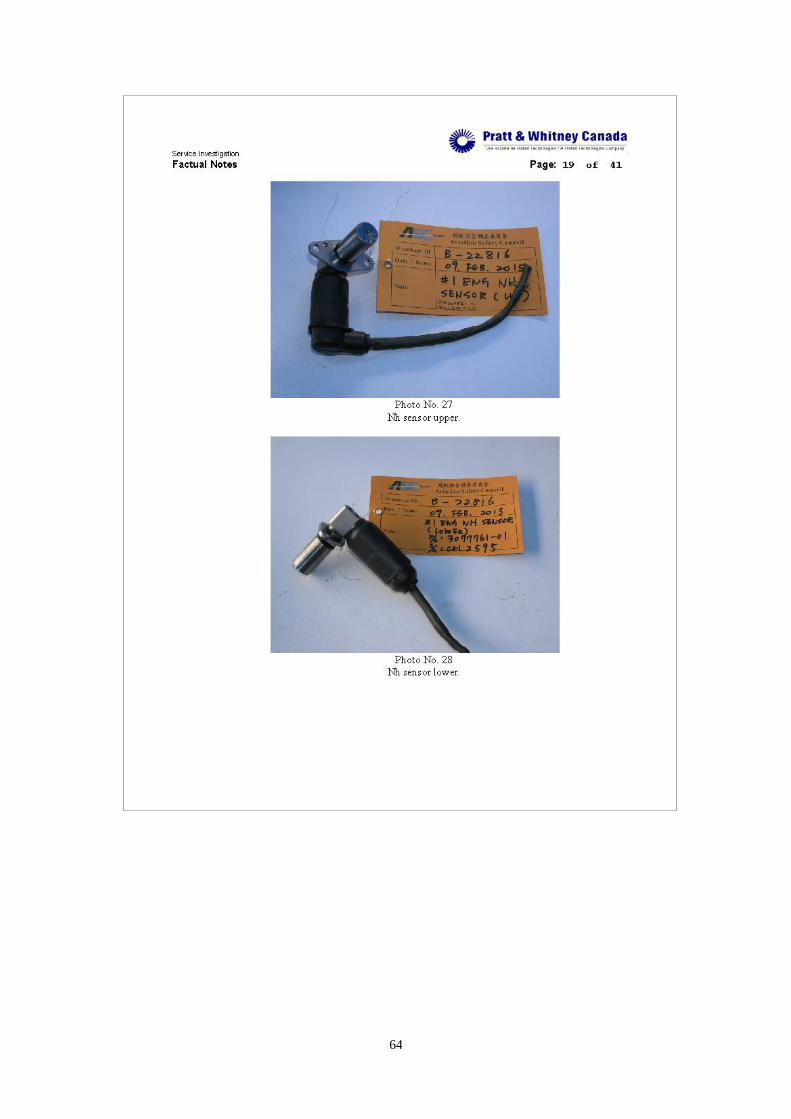
and lower Nh Sensors, Nl sensor and Np sensor.
1.16.3 Components test and examination1
1.16.3.1 AFUs tests
Two AFUs removed from the occurrence aircraft, and another AFU
removed from an ATR72 aircraft that experienced an uncommanded
autofeather event after the GE235 occurrence were sent to the
manufacturer, UTAS Rosemount Aerospace, in Minnesota, USA for test
and examination.
The test was performed at UTAS facility in Eagan/Burnsville,
Minnesota USA, during April 8-11, 2015. The attendees of this test
included representatives from safety boards (NTSB, BEA and ASC),
regulator (Transport Canada), Advisors (UTAS, PWC and ATR) and
observer (TransAsia Airways). The test was based on shop test for
functional testing and extended to laboratory examination. During the
shop test, a field notes (summary referred to Appendix 2, detail referred
to Attachment 13) was made by NTSB which documented key findings
and group decisions. BEA also prepared a Meeting Report of this AFUs
1 All the tests are conducted on post-impact components.
26
tests, document no. BEA2015-0039_tec10, referred to Attachment 3. The
Meeting Report provided more detailed test process and results, but not
including laboratory examination. After all necessary tests including
laboratory examination finished, NTSB provided ASC a full AFU
Investigation Report prepared by UTAS on June 11, 2015, document
number D06429311, Non Technical Rev A (referred to Attachment 4).
Following paragraphs are excerpts that relevant to occurrence AFUs from
the UTAS document and the BEA Meeting Report.
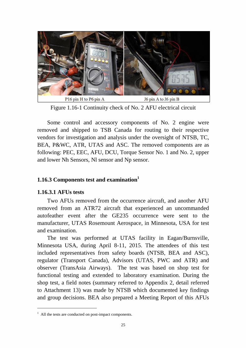
Basic information: Basic information of these 2 AFUs is shown in Table
1.16-2.
Table 1.16-2 AFUs basic information
Work performed
The following testing protocol for each AFU was agreed for all the
units before the meeting:
- Visual inspection
27
- Perform a continuity check ([Ref 1]2– page 125 and 126)
- Perform the functional tests manually ([Ref 1] – page 101 and 123)
- Perform the functional tests automatically [Ref 2]3
- Perform the thermal cycle tests ([Ref 1] – page 124)
- Perform the vibrations tests ([Ref 1] – page 129)
If a device failed a test, then the testing protocol would be adapted.
AFU No. 1
AFU No. 1 passed continuity test, manual functional tests, automatic
functional tests, thermal tests and vibration tests.
Findings for AFU No. 1
- AFU No. 1 passed all the tests in accordance with CMM [Ref 1]
AFU No. 2
AFU No. 2 failed to pass continuity test. The measured resistances
values for the Pins J and H were fluctuated from 1 to 20 ohms when the
ribbon was moved by hand. The resistance was higher than the CMM
(Component Maintenance Manual with Illustrated Parts List, 73-20-03,
Rev. 11, Oct 01, 2014) values threshold of 0.35 ohms for the Pins J and H.
These two pins are the pins connected with the torque sensor. An X-ray
examination was performed and no defect was found of this unit. In order
to find where the increased resistance occurred between Pin J/H of J2
connector and the A2 board strip contact (contact points No. 34/33), a
new test procedure was proposed and agreed by all attendees for this unit.
To perform the new test, three test points were defined to facilitate
the isolation of the high resistance.
X1 – The insulation was removed at the end of the flex to create
a testing point
X2 – The flange on the pin that is soldered between the flex
circuit and the circuit card
X3 – A testing point on the circuit card, instead of the strip
contact point defined in the CMM
Detail test results by applying the new test procedure for AFU No. 2
are as follows. 2 73-20-03 Rev11, Component Maintenance Manual, Part Number 30048-0000-* Part Testing and
Fault Isolation
3 D06409502 Rev C, Acceptance Test Procedure
28
The resistance (RX1) measured between pin J and point X1
provided a value consistent with the maximum resistance value
provided by the CMM. Moving the ribbon did not affect this
value.
The resistance (RX2) measured between pin J and point X2
provided a value greater than RX1, which was unstable and
changed while the ribbon was moved.
The resistance (RX3) measured between pin J and point X3
provided a value greater than RX1, which was unstable and
changed while the ribbon was moved.
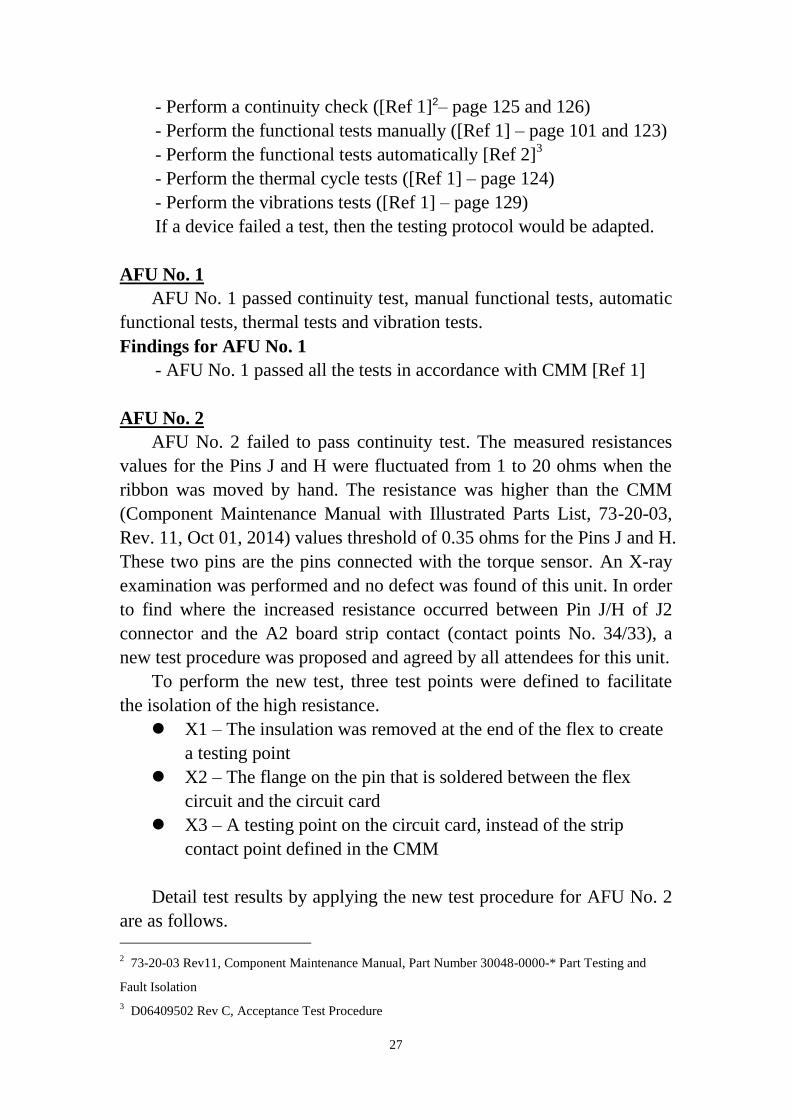
Figure 1.16-2 Continuity check of pin J and A2 board
It was noted that the first time RJ2 and RH2 were measured, both were
unstable. As the tests were repeated, from time to time, RJ2 and/or RH2
were stable during one test. The continuity failures detected on pin H and
pin J were located inside the header strip connector (end of the ribbon,
opposite to the J2 socket). The discontinuity was observed to be
intermittent. The test results are summarized in Table 1.16-3.
29
Table 1.16-3 Test results of AFU No. 2 by applying new test procedure
AFU No. 2
X1 X2 X3
Pin J Stable Unstable Unstable
Pin H Stable Unstable Unstable
The functional test of AFU No. 2 was not completed due to a short
circuit was detected during the gain tests. An X-ray examination was
performed and a possible cause was found on the bounding No. 16 of
component U5 of A2 board. As the component replacement could be seen
as a destructive choice, it was decided to stop the test with this unit.
A CT-Scan (Computed Tomography) of J2 solder joints was
performed and potential solder cracking was identified. A destructive test
was performed to find the possible root cause of continuity failures inside
the 90∘connector of J2 flex circuit. The J2 flex circuit was cut out of the
CCA (Circuit Card Assembly) and housing. Pins 33-42 of J2 flex circuit
was examined using optical microscope and with the SEM (Scanning
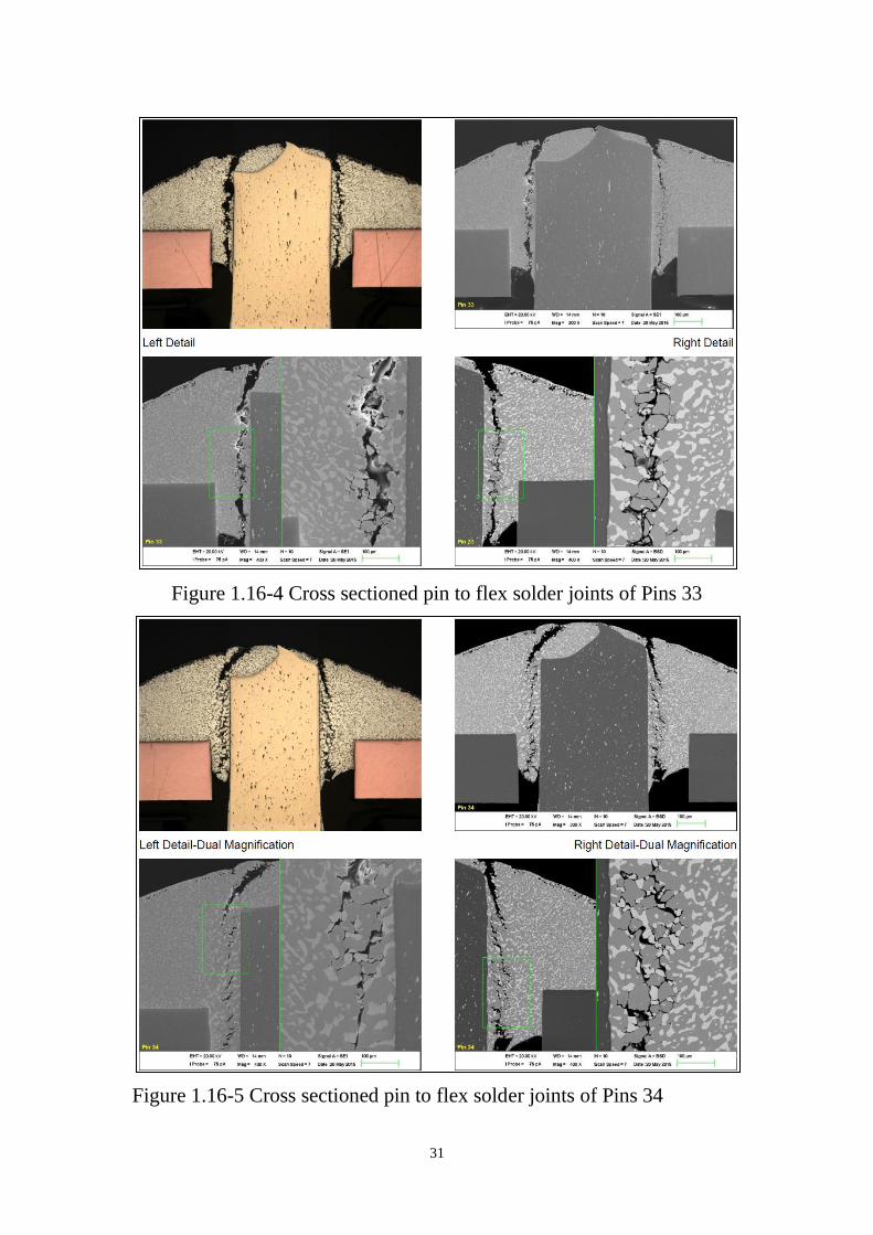
Electron Microscope). Figure 1.16-3 shows the photos of Pins 33 and 34
with 40X magnifications and with SEM examination. The Pins 33-42 of
J2 flex circuit was cross sectioned to the component centerline and
examined. Figure 1.16-4 and 1.16-5 show the photos of cross sectioned
pin to flex solder joints of Pins 33 and 34. The Pin-Flex solder joints
displayed a coursing of the solder micro structure near the pin on each of
the 10 pins in the strip. The condition was most advanced on pins near the
end of the strip. In the optical cross-section images the Lead-rich phase
are the grey particles dispersed within the white Tin-rich phase. In the
SEM images the Lead phase is white and Tin is grey. The solder
microstructure is enlarging, coarsening and cracking in a stress zone
adjacent to the Pin / Solder interface. Away from this “crack zone” the
solder microstructure is very fine.
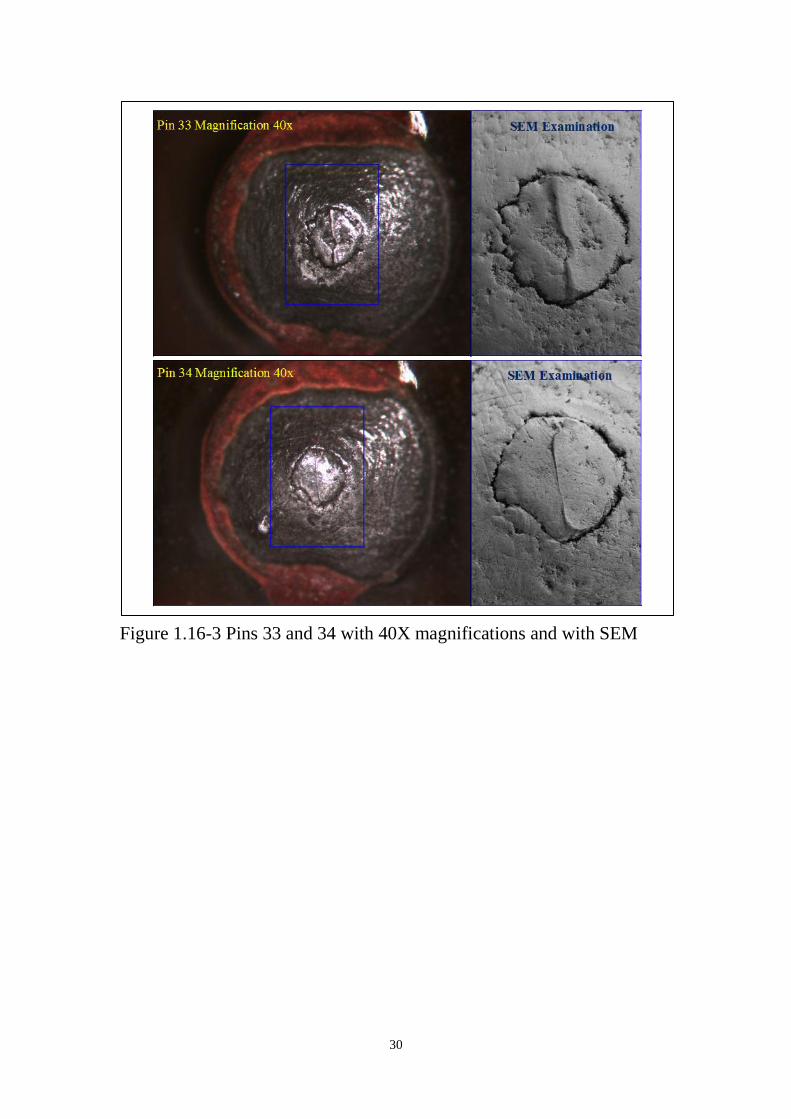
30
Figure 1.16-3 Pins 33 and 34 with 40X magnifications and with SEM
31
Figure 1.16-4 Cross sectioned pin to flex solder joints of Pins 33
Figure 1.16-5 Cross sectioned pin to flex solder joints of Pins 34
32
Findings for AFU No. 2
- Continuity failures (resistance values above the CMM threshold)
exist between pin H and the circuit board, and between pin J and
the circuit board
- Continuity failures (resistance values above the CMM threshold)
are located at the solder joint interface between the flex circuit and
the header pin
- Continuity failures (resistance values above the CMM threshold)
were inconstant
- The solder microstructure is enlarging, coarsening and cracking in
a stress zone adjacent to the solder joint interface between the flex
circuit and the header pin
1.16.3.2 MFCs NVM data download
Twenty two boards of two Multi Function Computers (MFC 1, 2)
were removed from the occurrence aircraft and shipped to BEA for NVM
data readout. BEA provided the Final report of the Computer MFC 1 and
computer MFC 2 Memories readout, document no. BEA2015-0039_tec11,
date of issue 16/04/2015, referred to Attachment 5. Following paragraphs
are excerpts of the document.
Four memory chips extracted from boards CPU1 and CPU2 of MFC
1 and MFC 2 were dried and electrically checked before the readout
processes. The memories were readout twice to check the correctness of
the downloaded binary files. The binary file of each memory was then
decoded by BEA and Airbus and the same results were found.
Information stored in the memory chips included 3 groups of readout,
Basic BITE, Advanced BITE and Super advanced BITE.
The only information provided by the basic BITE memories is that
from the CPU2 of MFC 1. The only recorded failure is the code 02 of the
system “flight control”, no other failure had been detected since the last
MFC maintenance action4, with an erase of the memory.
Advanced BITE and Super Advanced BITE provided following
information,
4 TNA information: TNA checks MFC memory every Wednesday night during weekly check. If only
WOW (Weight On Wheel) failure code existed, the memory will be erased. If there were failure code
other than WOW, the associated correction will be documented in the TLB. From the maintenance
records, the last weekly check of the occurrence aircraft was performed on January 28, 2015 with no
fault found.

33
During the 6 of the 8 previous flights (no event for flight N-1 and
N-2), the code 02 appeared in the group “flight control” (advanced BITE).
The meaning of this code and the associated action are the following:
TORQUE 2 FAULT (confirmation delay: 30 s)
This code appears with the following conditions:
right power lever in TO position AND torque below
25%
OR right power lever not in TO position AND torque
upper 50%
AND right ECU not fault
AND right engine oil not in low pressure
AND MFC1B or 2B valid.
Action:
Check AFU, Torque indicator, microswitch on right
power lever and associated wiring.
When this failure occurs, it shall be underlined that:
the failure concerns a chain composed of {TQ sensor #1 of
engine #2, harness, AFU #2}
it is impossible to know what element of the chain failed.
the exit of the system is the needle TQ indication displayed
on the EPD. This failure has then an impact on the
information displayed to the crew.
the digital TQ indication displayed on the EPD uses another
chain and another sensor (TQ sensor #2 of the engine). It is
this information, which is recorded by the DFDR.
All those flights were performed the day before the flight of the event
(2015/02/04).
The flights N-1 and N-2 were performed the same day than the flight
of the event (2015/02/04). It is impossible to know if the crew faced or
not the same failure during these two flights:
no indication of ATPCS sequence exists on the FDR
recorded data (no feathering request recorded inside the FDR
and the super advanced BITE)
after the take off, it is impossible to know if the needle TQ
indication of the engine #2 was invalid as the information of
the torque values recorded by the FDR is provided by
34
another chain using the TQ sensor #2
as the confirmation delay for the MFC to record this failure
is 30 seconds, this failure might have happened
intermittently, for durations lower than 30 seconds.
During the flight of the event, MFC #2 recorded an autofeather
request inside the super-advanced BITE, with a signal coming from the
AFU No. 2. Both module 2A and 2B recorded the same context:
A single record
Code E1: Activation signal for feathering pump 2 status
Code E3: Auto feathering signal from AFU No. 2
This recording is consistent with the record of the code 02 of the
group “flight controls”, recorded inside the advanced BITE during the
flight of the event (all the MFC modules). As the right power lever was
recorded in the take off position by the FDR, the torque indication value
was then detected below 25%.
During the flight N-1, the Super Advanced BITE information seems
not consistent for the propeller brake recorded context. Both MFC 2A and
2B modules performed the same first record, but the module 2B
performed 2 additional records. This has no impact on the investigation of
the event. Nevertheless, ATR is investigating these differences.
FINDINGS
No error other than the invalid needle TQ indication was
detected by the MFC since the last erase of the MFC
memory (maintenance action)
AFU #2 reported TQ values of the engine #2 lower than 25%
to the MFC during more than 30 s.
The auto feathering triggered during the flight of the event.
1.16.3.3 PECs and EECs data download
Two EECs and 2 PECs removed from the occurrence aircraft were
sent to manufacturer, Hamilton Sundstrand at Windsor Locks,
Connecticut, USA, for NVM data download. The work was performed by
Hamilton Sundstrand and overseen by the representatives from NTSB,
TC and P&WC during the time period April 20-22, 2015. The Shop
Findings Report of EECs and PECs, referred to Attachment 6, was
35
provided to ASC on May 20, 2015. Following is the basic information of
the EECs and the PECs,
Table 1.16-4: Basic information of EEC and PEC
P/N S/N Position
EEC 1012974-4-002 14040035 No.1 / left
EEC 1012974-4-002 13100020 No.2 / right
PEC 816332-5-401 13070018 No.1 / left
PEC 816332-5-401 13080013 No.2 / right
The shop finding and data download indicated that both PECs had no
induced failures and no fault codes stored during the occurrence flight.
Both EEC passed power up test with some stored fault codes. Each of the
fault codes occurred on a flight prior to the event and was most probably
caused by the power-up sequence of the EEC, DCU, AFU, Air Data
Computer.
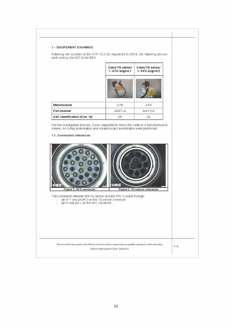
1.16.3.4 Harnesses
The harnesses connecting No. 1 torque sensors to AFU of both
engines were removed from the occurrence aircraft and shipped to BEA
for further lab examination. A non-destructive means was performed by
using an X-ray and a macroscopic examination (Appendix 3). The
connection between the torque sensor and the AFU is made through
(Figure 1.16-6):
Pin No. 1 and pin No. 2 on the torque sensor connector
Pin H and pin J on the AFU connector
Figure 1.16-6 Torque sensor and AFU connectors
36
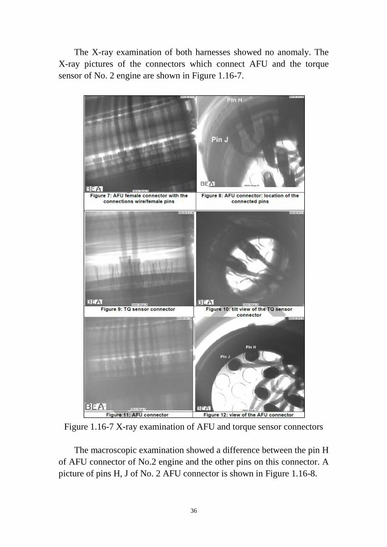
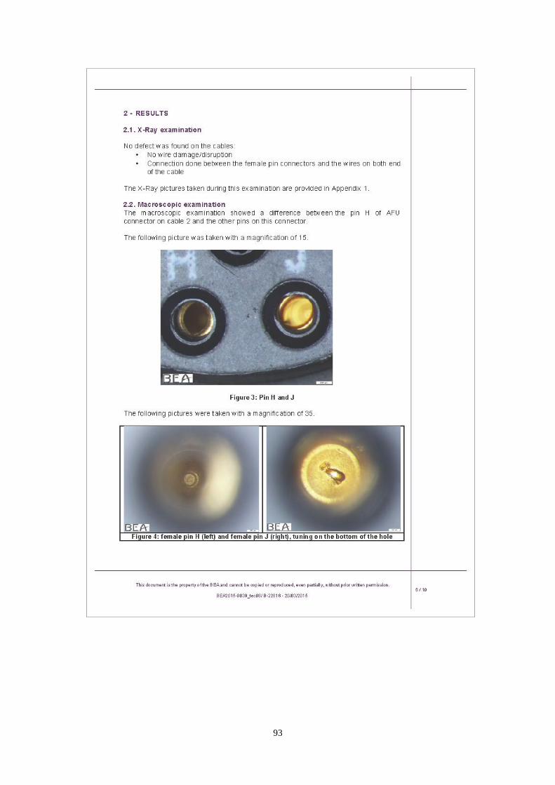
The X-ray examination of both harnesses showed no anomaly. The
X-ray pictures of the connectors which connect AFU and the torque
sensor of No. 2 engine are shown in Figure 1.16-7.
Figure 1.16-7 X-ray examination of AFU and torque sensor connectors
The macroscopic examination showed a difference between the pin H
of AFU connector of No.2 engine and the other pins on this connector. A
picture of pins H, J of No. 2 AFU connector is shown in Figure 1.16-8.

37
Figure 1.16-8 Pins H and J of No. 2 AFU connector
The harness was brought to UTAS Rosemount Aerospace to combine
with the AFU test if situation required. Because of the discontinuity was
found in AFU No.2, ASC requested just to perform the continuity check
of harness. A continuity check then was done on the pin J and H of
harness. The resistances were 0.20 ohms and 0.21 ohms respectively.
1.16.3.5 Accessories tests
Twelve engine sensors including right torque, left torque, Np speed,
lower Nh speed, upper Nh speed and Nl speed sensors of No. 1 and No. 2
engines which removed from the occurrence aircraft were sent to P&WC
via TSB for testing. After all necessary tests finished, P&WC provided
ASC a report on June 22, 2015, document number RFA No 15ECN00082
SI File No: 15-006 (referred to Attachment 7). According to the report,
observations recorded from testing of the speed and torque sensors were
indicative of immersion in water and impact. Test results are summarized
in Appendix 4.
Two Data Collection Units (DCUs) which removed from No. 1 and
No. 2 engines of the occurrence aircraft after the crash were sent to the
manufacturer, Safran Electronics, via TSB for memory data readout.
According to Attachment 7, the readout data from the DCU of both
engines did identified engine cycle count and engine run-time data.
38
1.18 Additional information
1.18.1 Interview summaries
1.18.1.1 Assistant manager of maintenance division
The interviewee first introduced TNA’s maintenance difficulty
reporting procedures and how the difficulty was reported. TNA’s
Maintenance Control Center (MCC) collects reported aircraft defects
from all stations and compiles them into a daily report each day. These
defects might be from pilot report, safety department or maintenance
personnel etc. A printed out daily report was prepared and used for
reference during TNA’s directors meeting. MCC assists directors of each
division to review the daily report as necessary. If there were service
difficulty item, MCC would report this item to Quality Control Center
(QCC). QCC also compulsorily needed to make Service Difficulty Report
(SDR) and reporting the difficulty to the Civil Aeronautics
Administration (CAA). After the SDR was reported to the CAA, TNA’s
Reliability Control Board (RCB) would discuss with CAA personnel for
solution of the service difficulty case.
Regarding the issues of aircraft diversion resulted from engine
problems during B-22816 ferry flight from Bangkok to Taiwan, the
interviewee expressed how those engine problems were reported to
Taiwan CAA. While the aircraft B-22816 was in cruise from Toulouse to
Taipei, a low oil pressure warning on the No. 1 engine occurred. The
flight crew shut down the No. 1 engine and diverted to Macau airport.
TNA replaced of the No. 1 engine to resume the aircraft delivery flight.
During the flight from Macau to Taipei, the No. 1 engine low oil pressure
warning appeared again and the flight crew shut down the No. 1 engine.
The investigation confirmed that the missing drive shaft / spur gear
woodruff key of the No. 1 engine reduction gearbox oil scavenge pump
was the cause of the engine low oil pressure warning. When the aircraft
B-22816 was diverted to land at Macau airport, TNA on board aircraft
personnel with the ferry flight called TNA Flight Control Center (FCC)
about the diversion. TNA FCC then reported the event to CAA. Due to
39
the repeated No. 1 engine low oil pressure warning and commanded in
flight shut down events, CAA sent Principal Maintenance Inspector (PMI)
to Kaohsiung airport to assist TNA after the aircraft B-22816 landed at
Kaohsiung airport.
While being asked what TNA’s actions taken and response to those
in flight shut down events in the latest 5 years were, the interviewee
replied that 2 of those in flight shut down events occurred during aircraft
delivery were mentioned earlier. One engine in flight shut down event
occurred in May 2, 2012 was resulted from manufacturing defect of
engine turbine blades which had been investigated and closed by the ASC.
The incident occurred on August 16, 2011 was resulted from defective J1
and J2 connectors of the Auto Feather Unit (AFU). TNA revised ATR
Continuous Airworthiness Maintenance Program (CAMP) task number
771362-RAI-10000-TNA to change the inspection of AFU to hard time
interval. The last one occurred in October 6, 2010 was due to engine
torque fluctuation after take-off. To reduce loss of engine torque signal or
torque fluctuations related event, TNA issued Engineering Circular
EC-1106-04 requesting the compliance of related documents and
procedures to perform electrical connector care.
1.18.1.2 Maintenance personnel stationed in Kinmen airport
The interviewee has worked for TNA since 1995. He has CAA’s
A/E/AV licenses and stationed in Kinmen airport as a senior mechanics
now. The interviewee received ATR72-500 type training and
configuration differences course training between the ATR72-500 and
-600 aircrafts. The interviewee also received aviation maintenance related
recurrent training each year. The interviewee then described how to
follow the procedures to authorize and dispatch aircraft after completion
of required check and maintenance.
While being asked what work had been done before the aircraft
B-22816 was dispatched to service the previous flight of the occurrence
flight from Kinmen to Songshan, the interviewee replied that there were
two mechanics stationed in Kinmen airport, since the other one had no
CAA license, the mechanics with no CAA license performed fueling
work and the interviewee did the transit check alone. The interviewee
40
finished the transit check in 20 minutes with no fault found. Usually, if no
fault was found, transit check could be done in about 20 to 25 minutes.
The interviewee also checked maintenance records; there was no deferred
defect of the aircraft B-22816. The interviewee then signed the Technical
Log Book and the aircraft was airworthiness released for service. After
the other mechanics finished fueling job, the interviewee walked to the
cockpit and gave the fueling form to the Captain. The flight crew did not
mention any problem about the engines.
If there were fault found before the aircraft departure, the interviewee
never discussed with the flight crew to apply MEL for delay maintenance.
Delay of aircraft scheduled departure time would not bring any pressure
on him. The interviewee said keeping aircraft airworthiness was the first
priority.
1.18.1.3 Maintenance personnel stationed in Songshan airport
The interviewee has worked for TNA since 2005. Before that he had
been in the Dragon Air for 2.5 years. He has CAA’s A/E/AV licenses,
and is stationed in Songshan airport as a mechanic now. The interviewee
had received ATR72-500 type training and configuration differences
course training between the ATR72-500 and -600 aircrafts. The
interviewee also received aviation maintenance related recurrent training
each year. The interviewee then described how to follow the maintenance
procedures to dispatch aircraft after completion of required check and
maintenance.
The transit check before the occurrence flight was done by the
interviewee. The transit check was finished in 20 minutes with no fault
found. The interviewee expressed that if no fault was found, transit check
usually could be done in about 20 minutes. The interviewee also checked
maintenance records and no deferred defect record of the aircraft
B-22816 was found. The interviewee then signed the Technical Log Book
and the aircraft was airworthiness released to service.
The interviewer asked whether or not the flight crew mentioned
about engine problem before the occurrence flight from Songshan to
Kinmen. The interviewee replied that the first leg of that day was flight
41
GE231. The interviewee did a pre-flight check while the Captain
performed a 360 degree check. The pre-flight check result was normal.
Before the leg of flight GE235, the interviewee did the transit check
himself. The flight crew did not mention anything about the engine. If
there were fault found before the aircraft departure, the interviewee never
bargained with the flight crew to apply MEL for delay maintenance.
Delay of aircraft scheduled departure time would not bring any pressure
on him. The interviewee said keeping aircraft airworthiness was the first
priority.
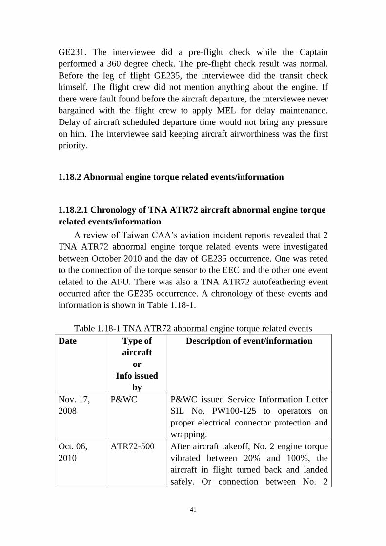
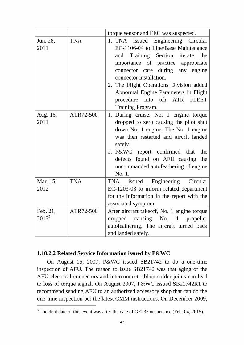
1.18.2 Abnormal engine torque related events/information
1.18.2.1 Chronology of TNA ATR72 aircraft abnormal engine torque
related events/information
A review of Taiwan CAA’s aviation incident reports revealed that 2
TNA ATR72 abnormal engine torque related events were investigated
between October 2010 and the day of GE235 occurrence. One was reted
to the connection of the torque sensor to the EEC and the other one event
related to the AFU. There was also a TNA ATR72 autofeathering event
occurred after the GE235 occurrence. A chronology of these events and
information is shown in Table 1.18-1.
Table 1.18-1 TNA ATR72 abnormal engine torque related events
Date Type of
aircraft
or
Info issued
by
Description of event/information
Nov. 17,
2008
P&WC P&WC issued Service Information Letter
SIL No. PW100-125 to operators on
proper electrical connector protection and
wrapping.
Oct. 06,
2010
ATR72-500 After aircraft takeoff, No. 2 engine torque
vibrated between 20% and 100%, the
aircraft in flight turned back and landed
safely. Or connection between No. 2
42
torque sensor and EEC was suspected.
Jun. 28,
2011
TNA 1. TNA issued Engineering Circular
EC-1106-04 to Line/Base Maintenance
and Training Section iterate the
importance of practice appropriate
connector care during any engine
connector installation.
2. The Flight Operations Division added
Abnormal Engine Parameters in Flight
procedure into teh ATR FLEET
Training Program.
Aug. 16,
2011
ATR72-500 1. During cruise, No. 1 engine torque
dropped to zero causing the pilot shut
down No. 1 engine. The No. 1 engine
was then restarted and aircrft landed
safely.
2. P&WC report confirmed that the
defects found on AFU causing the
uncommanded autofeathering of engine
No. 1.
Mar. 15,
2012
TNA TNA issued Engineering Circular
EC-1203-03 to inform related department
for the information in the report with the
associated symptom.
Feb. 21,
20155
ATR72-500 After aircraft takeoff, No. 1 engine torque
dropped causing No. 1 propeller
autofeathering. The aircraft turned back
and landed safely.
1.18.2.2 Related Service Information issued by P&WC
On August 15, 2007, P&WC issued SB21742 to do a one-time
inspection of AFU. The reason to issue SB21742 was that aging of the
AFU electrical connectors and interconnect ribbon solder joints can lead
to loss of torque signal. On August 2007, P&WC issued SB21742R1 to
recommend sending AFU to an authorized accessory shop that can do the
one-time inspection per the latest CMM instructions. On December 2009, 5 Incident date of this event was after the date of GE235 occurrence (Feb. 04, 2015).
43
P&WC moved the intend of SB21742R1 in Table 4 of section 05-20-00
of the Engine Maintenance Manual (P/N 3037332, rev. 42) to change this
inspection to a repeat inspection. P&WC then cancelled the SB21742 in
April 2011 because it is now covered in the Engine Maintenance Manual.
On December 14, 2010, P&WC issued Service Information Letter
(SIL) No. PW100-138 (see attachment 9) for AFU inspection / repair at
shop visits. The document indicated that some of the AFUs involved in
those autofeather events exhibited cracks in the soldering of the U3
voltage converter mounted on the AFU board. Those cracks are believed
to have caused momentary electrical disruptions leading to the autofeath
events. The manufacturer of the AFU then revised instructions regarding
the U3 converter inspection, installation and soldering to its mounting
board. In addition, testing requirements for the AFU have been improved
via testing at low, high and ambient temperatures.
On September 26, 2011, P&WC issued Service Information Letter
No. PW100-147 (see attachment 10) for AFU related autofeather events.
The document indicated that several of the reported autofeather events are
associated to 28 Volts DC power interruptions at the AFU. On the ATR
aircraft, those power interruptions will generate large magnitude torque
bug fluctuations. The AFU manufacturer has incorporated related
contents to its CMM which include:
Revised instructions for U3 converter inspection, installation
and soldering on the mounting board.
Inspections related to the J1 and J2 flex conductors and boards
interconnect flexible ribbons.
Functionality testing of the AFU at different temperature (low,
high and ambient).
1.18.3 Wreckage and LRU database
Two wreckage databases (structure database and LRUs database, as
shown in Attachment 11, 12) were developed using an Excel spread sheet
for records keeping and information sharing. The structure database
containing 38 pieces of larger wreckage recovered from the aircraft crash
site. Data fields of the structure database contain parts nomenclature,
location, results of structure examination and related photos. The LRU
44
database containing 68 line replacement units removed from cockpit and
No. 1, 2 engines. Data fields of the LRU database contain item
nomenclature, part number, serial number, wet or dry status, shipping
information (TSB/BEA/ASC) and related photos.
45
IV. Appendix
1. ATR-72 Reg. B-22816 Accident Investigation, Engine Inspection
Factual Notes
2. Summary of Field Notes, Examination of Autofeathering Units at
UTAS Rosemount Aerospace, Burnsville, Minnesota, April 8-11,
2015
3. Technical document, Cable TQ sensor – AFU engine 1 & 2, X-Ray
and macroscopic examination report, BEA2015-0039-tec08,
20/03/2015
4. Test results of torque and speed sensors

46
Appendix 1. ATR-72 Reg. B-22816 Accident Investigation, Engine
Inspection Factual Notes

47

48

49

50
51

52

53
54
55

56

57
58
59

60
61
62

63
64

65
66

67

68
69

70
71
72

73
74
75
76
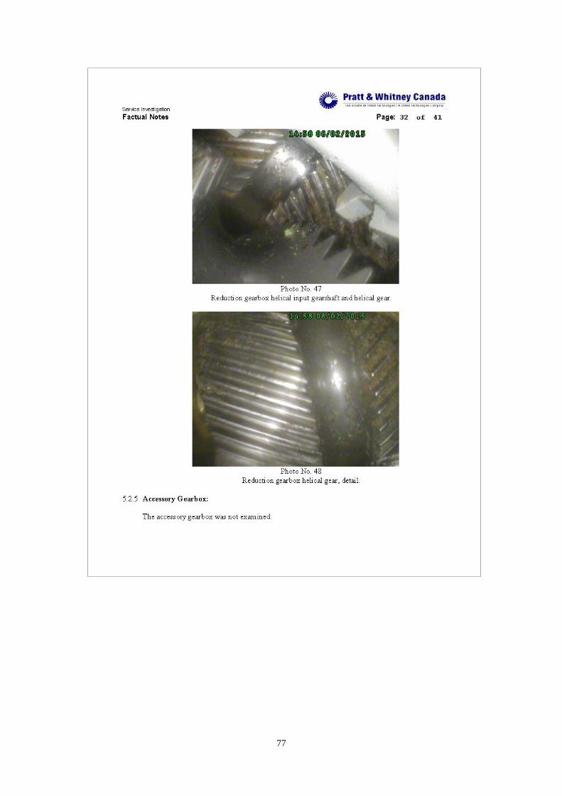
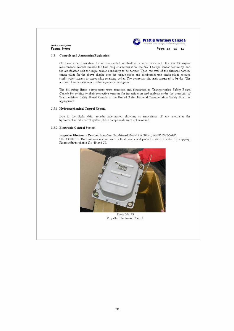
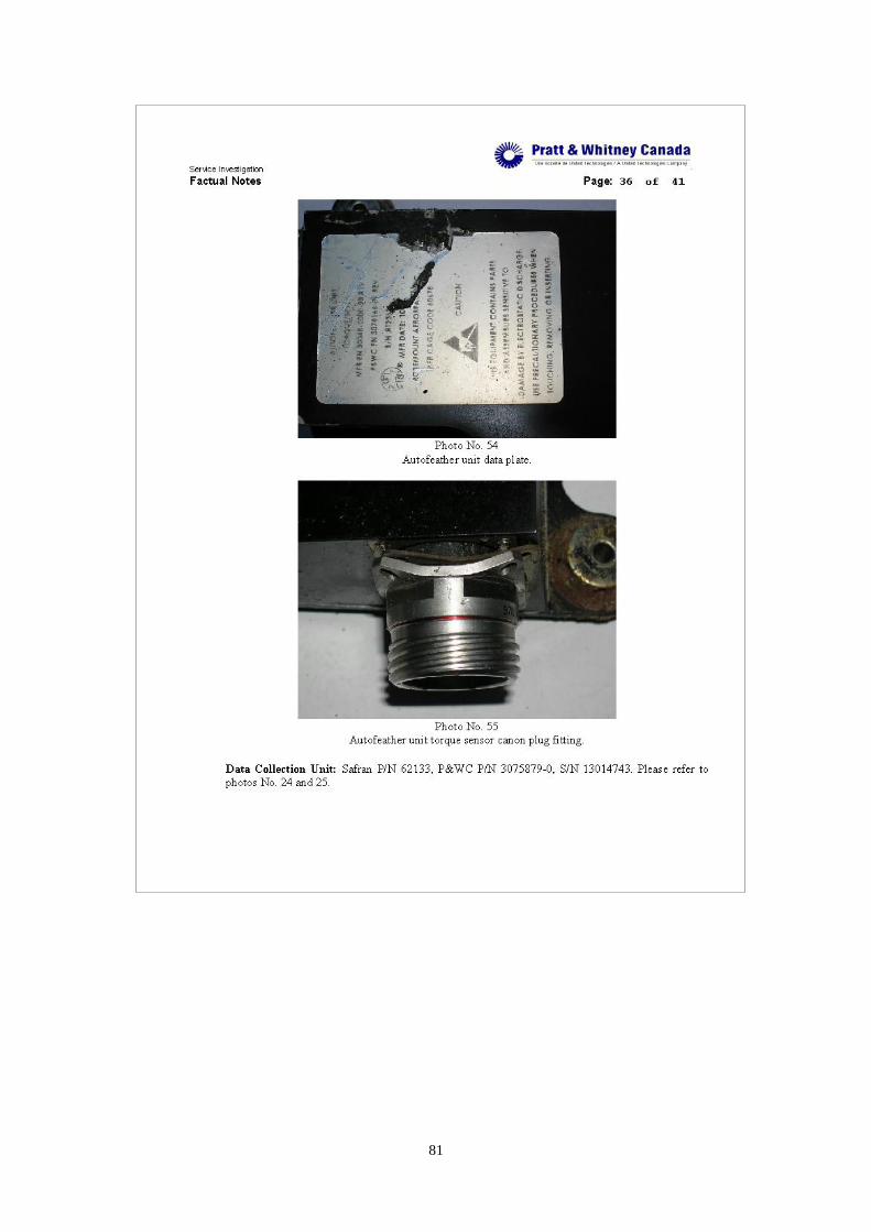
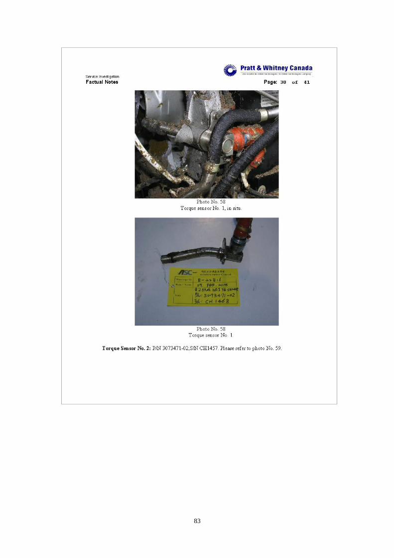
77
78

79

80
81

82
83
84

85

86
87
Appendix 2. Summary of Field Notes, Examination of Autofeathering
SUMMARY
On February 04, 2015, TransAsia Airways (TNA) passenger flight GE235, an
ATR72-212A aircraft, took off from Taipei bound for Kinmen. Just after take-off, the
No. 2 engine propeller was feathered automatically. About 40 second later, engine No.
1 was manually shutdown. The aircraft crashed into Keelung River of Nankang
section at 1053 Taipei time.
The UTAS Rosemount Aerospace autofeather units (AFUs) removed from the
occurrence aircraft, and another AFU removed from an ATR72 aircraft that
experienced an uncommanded autofeather event following the GE235 occurrence
were tested at UTAS Rosemount Aerospace facilities in Eagan/Burnsville, Minnesota
April 8 – 11, 2015.
88
Appendix 3. Technical document, Cable TQ sensor – AFU engine 1 &
2, X-Ray and macroscopic examination report
89
90
91
92
93
94

95

96

97

98
Appendix 4. Test results of torque and speed sensors
No. 1 engine
Accessary P/N S/N Result
Torque
sensor left
3073471-01 CH1282 Satisfactory
Torque
sensor right
3073471-02 CH1734 1. Resistance check below
minimum limit of 40
mega-ohms (note 1)
2. Test point voltage slightly
below minimum limit of 1.5
volts
Np speed
sensor
3077761-01 CH2615 1. Three resistance checks
below minimum limit of 100
mega-ohms (note 1)
2. Resistance at each coil and
between the coils and the
housing was within limits
but fluctuating (note 2).
3. One of the wires was
detached from the pin.
Nh speed
sensor
(lower)
3077761-01 CH2595 1. Three resistance checks
below minimum limit of 100
mega-ohms (note 1)
Nh speed
sensor
(upper)
3077761-01 CH2610 1. Resistance check below
minimum limit of 100
mega-ohms
Nl speed
sensor
3033509H CH21092 Satisfactory
No. 2 engine
Accessary P/N S/N Result
Torque
sensor left
3073471-02 CH1468 1. Open circuit exited in a coil
winding resistance check.
2. Three test point voltages at
different RPM settings were
below minimum limit of
1.5/8.9/8.9 volts.
3. Voltage was erratic
99
throughout this series of
tests.
Torque
sensor right
3073471-02 CH1457 1. Two test point voltages at
different RPM settings were
slightly below minimum
limit of 1.5/8.9 volts.
Np speed
sensor
3077761-01 CH2128 Satisfactory
Nh speed
sensor
(lower)
3077761-01 CH2106 Satisfactory
Nh speed
sensor
(upper)
3077761-01 CH2108 Satisfactory
Nl speed
sensor
3033509H CH20768 Satisfactory
Note
1. This test point was repeated after heating the sensor at 100° C then allowing it to
cool to room temperature resulting in acceptable resistance.
2. Following heating of the sensor to 100° C and allowing it to cool to room
temperature there were no open circuit existed.

100
V. Attachment
1. V-3000/15 - GE235 Answer to Action Log Revision #4 Toulouse,
May 19th 2015
2. B-22816 Occurrence-Site Wreckage Field Notes
3. Technical document, AFUs tests, BEA2015-0039_tec10, 12/04/2015
4. AFU INVESTIGATION Document Number D06429311, Non
Technical Rev A
5. Technical document, Computer MFC 1 and computer MFC 2
Memories readout, BEA2015-0039_tec11, 16/04/2015
6. Records of EEC, PEC NVM data downloads
7. ACCESSARIES ACCIDENT REPORT, document number RFA No
15ECN00082 SI File No: 15-006
8. Service Bulletin, P&WC SB No. 21742R2, Apr 01, 2011
9. Service Information Letter, P&WC SIL No. PW100-138, December
14, 2010
10. Service Information Letter, P&WC SIL No. PW100-147, September
26, 2011
11. Wreckage structure database
12. Wreckage LRUs database
13. Field notes, examination of Autofeathering Unit
Recommended