FRONT SUSPENSION AND AXLE
CONTENTS
page page
AXLE NOISE/VIBRATION DIAGNOSIS . . . . . . . . 13FRONT SUSPENSION . . . . . . . . . . . . . . . . . . . . . 9FRONT WHEEL ALIGNMENT . . . . . . . . . . . . . . . 4
GENERAL INFORMATION . . . . . . . . . . . . . . . . . . 1MODEL 30 AXLE AND TUBE AXLE (2WD) . . . . 17TORQUE SPECIFICATIONS . . . . . . . . . . . . . . . . 41
GENERAL INFORMATION
FRONT SUSPENSIONThe Grand Cherokee front suspension is a link/coil
design comprised of (Fig. 1);• Drive axle (4WD), tube axle (2WD)• Track bar• Stabilizer bar• Upper and lower suspension arms• Coil springs• Dual-action shock absorbers• Jounce bumpers (used to limit the travel of thesuspension)
The front suspension is designed to allow eachwheel to adapt to different road surfaces withoutgreatly affecting the opposite wheel. The wheels aremounted to hub/bearings that ride on tapered bear-ings on the steering knuckle. The hub/bearing designis not serviceable and is replaced as a unit only. Thesteering knuckles turn (pivot) on replaceable ballstuds mounted on the axle tube yokes.
The upper and lower suspension arms use bushingsto isolate road noise. The suspension arms are boltedto the frame and axle through the rubber bushings.The lower suspension arm uses cam bolts at the axle
Fig. 1 Front Suspension
Z FRONT SUSPENSION AND AXLE 2 - 1
to allow for caster and pinion angle adjustment. Thesuspension arm travel (jounce or rebound) is limitedthrough the use of rubber bumpers.
All suspension components that use rubber bush-ings should be tightened with the vehicle at normalheight. If the springs are not at their normal rideposition, vehicle ride comfort could be affected. Rub-ber bushings must never be lubricated.
The vehicles use coil springs mounted up in thefender shield that is part of the unitized body bracket.There is a rubber doughnut isolator between the topof the spring and bracket. The bottom of the springseats on the axle pad and is retained with a clip.
Ride control is accomplished through the use ofdual-action shock absorbers. The shocks dampen thejounce and rebound as the vehicle travels over vari-ous road conditions. The top of the shock absorbersare bolted to the frame. The bottom of the shocks arebolted to the axle spring bracket.
The stabilizer bar is used to minimize vehicle frontsway during turns. The spring steel bar helps toequalize the vehicle body in relationship to the sus-pension. The bar extends across the front undersideof the chassis and connects to the frame rails. Thelinks are connected to the axle brackets. All mountingpoints of the stabilizer bar are isolated by rubberbushings.
The track bar is used to minimize front axle side-to-side movement. The track bar is attached to theframe rail bracket with a ball stud and isolated witha bushing at the axle bracket.
FRONT DRIVE AXLEThe integral type housing, has the centerline of the
pinion set below the centerline of the ring gear.The axles are equipped with A.B.S. brake systems.
The A.B.S. tone rings are pressed onto the axle shaftnear the hub and knuckle. For additional informationon the A.B.S. system refer to Group 5, Brakes.
The Model 30 axle has the assembly part numberand gear ratio listed on a tag. The tag is attached tothe housing cover (Fig. 2). Build date identificationcodes are stamped on the axle shaft tube cover side.
STANDARD DIFFERENTIAL OPERATIONThe differential gear system divides the torque be-
tween the axle shafts. It allows the axle shafts torotate at different speeds when turning corners.
Each differential side gear is splined to an axleshaft. The pinion gears are mounted on a pinion mateshaft and are free to rotate on the shaft. The piniongear is fitted in a bore in the differential case and ispositioned at a right angle to the axle shafts.
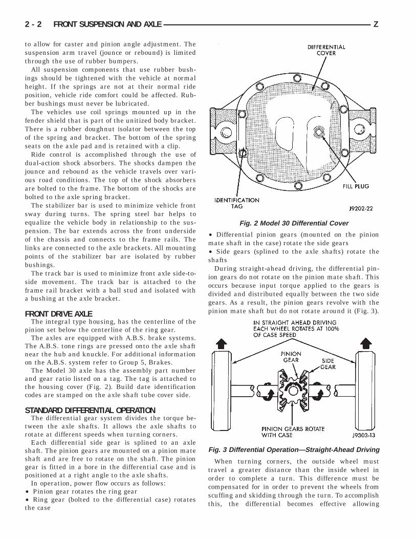
In operation, power flow occurs as follows:• Pinion gear rotates the ring gear• Ring gear (bolted to the differential case) rotatesthe case
• Differential pinion gears (mounted on the pinionmate shaft in the case) rotate the side gears• Side gears (splined to the axle shafts) rotate theshafts
During straight-ahead driving, the differential pin-ion gears do not rotate on the pinion mate shaft. Thisoccurs because input torque applied to the gears isdivided and distributed equally between the two sidegears. As a result, the pinion gears revolve with thepinion mate shaft but do not rotate around it (Fig. 3).
When turning corners, the outside wheel musttravel a greater distance than the inside wheel inorder to complete a turn. This difference must becompensated for in order to prevent the wheels fromscuffing and skidding through the turn. To accomplishthis, the differential becomes effective allowing
Fig. 2 Model 30 Differential Cover
Fig. 3 Differential Operation—Straight-Ahead Driving
2 - 2 FRONT SUSPENSION AND AXLE Z

the axle shafts to turn at unequal speeds (Fig. 4). Inthis instance, the input torque applied to the piniongears is not divided equally. The pinion gears nowrotate around the pinion mate shaft in opposite direc-tions. This allows the side gear and axle shaft at-tached to the outside wheel to rotate at a fasterspeed.
TUBE AXLE (2WD VEHICLES)The front axle used on two-wheel drive vehicles is a
one-piece, tubular axle (Fig. 5). The tubular axlemounts in the same bracketry as does the four-wheeldrive front axle. The steering knuckles and hub bear-ing assemblies are the same as used on the Model 30drive axle.
Fig. 4 Differential Operation—On Turns
Fig. 5 Front Axle— 2WD Vehicles
Z FRONT SUSPENSION AND AXLE 2 - 3
FRONT WHEEL ALIGNMENT
GENERAL INFORMATIONFront wheel alignment involves the correct position-
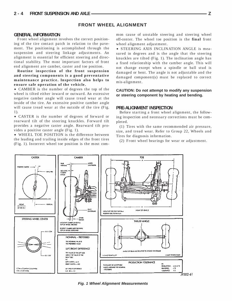
ing of the tire contact patch in relation to the pave-ment. The positioning is accomplished through thesuspension and steering linkage adjustments. Analignment is essential for efficient steering and direc-tional stability. The most important factors of frontend alignment are camber, caster and toe position.
Routine inspection of the front suspensionand steering components is a good preventativemaintenance practice. Inspection also helps toensure safe operation of the vehicle.• CAMBER is the number of degrees the top of thewheel is tilted either inward or outward. An excessivenegative camber angle will cause tread wear at theinside of the tire. An excessive positive camber anglewill cause tread wear at the outside of the tire (Fig.1).• CASTER is the number of degrees of forward orrearward tilt of the steering knuckles. Forward tiltprovides a negative caster angle. Rearward tilt pro-vides a positive caster angle (Fig. 1).• WHEEL TOE POSITION is the difference betweenthe leading and trailing inside edges of the front tires(Fig. 1). Incorrect wheel toe position is the most com-
mon cause of unstable steering and steering wheeloff-center. The wheel toe position is the final frontwheel alignment adjustment.• STEERING AXIS INCLINATION ANGLE is mea-sured in degrees and is the angle that the steeringknuckles are tilted (Fig. 1). The inclination angle hasa fixed relationship with the camber angle. This willnot change except when a spindle or ball stud isdamaged or bent. The angle is not adjustable and thedamaged component(s) must be replaced to correctmis-alignment.
CAUTION: Do not attempt to modify any suspensionor steering component by heating and bending.
PRE-ALIGNMENT INSPECTIONBefore starting a front wheel alignment, the follow-
ing inspection and necessary corrections must be com-pleted.
(1) Tires with the same recommended air pressure,size, and tread wear. Refer to Group 22, Wheels andTires for diagnosis information.
(2) Front wheel bearings for wear or adjustment.
Fig. 1 Wheel Alignment Measurements
2 - 4 FRONT SUSPENSION AND AXLE Z
(3) Ball studs and linkage pivot points, steeringgear for looseness, roughness, binding or a stickingcondition. Refer to Group 19, Steering for additionalinformation.
(4) Front wheels for excessive radial, lateral runoutand unbalance. Refer to Group 22, Wheels and Tiresfor diagnosis information.
(5) Suspension components for wear and noise.Check components for correct torque. Refer to Groups2 and 3, Suspension and Axle for additional informa-tion.
ALIGNMENT MEASUREMENTS AND ADJUST-MENTS
Before each alignment reading the vehicle shouldbe jounced (rear first, then front). Grasp each bumper
at the center and jounce the vehicle up and downseveral times. Always release the bumper when it’s atthe down position. Set the front end alignment tospecifications while the vehicle is in its NOR-MALLY LOADED CONDITION.
CAMBERThe wheel camber angle (Fig. 1) is preset at NEGA-
TIVE 0.25 DEGREES (-0.25°). The angle is not ad-justable and cannot be altered.
Z FRONT SUSPENSION AND AXLE 2 - 5
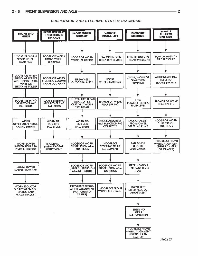
SUSPENSION AND STEERING SYSTEM DIAGNOSIS
2 - 6 FRONT SUSPENSION AND AXLE Z
CASTERThe caster angle (Fig. 1) is set at POSITIVE 7
DEGREES (+7°).Check the caster of the front axle for correct angle.
Be sure the axle is not bent or twisted. Road test thevehicle and observe the steering wheel return-to-center position. Low caster will cause poor steeringwheel returnability.
During the road test, turn the vehicle to both theleft and right. If the steering wheel returns to thecenter position unassisted, the caster angle is correct.However, if steering wheel does not return toward thecenter position unassisted, an incorrect caster angleis probable.
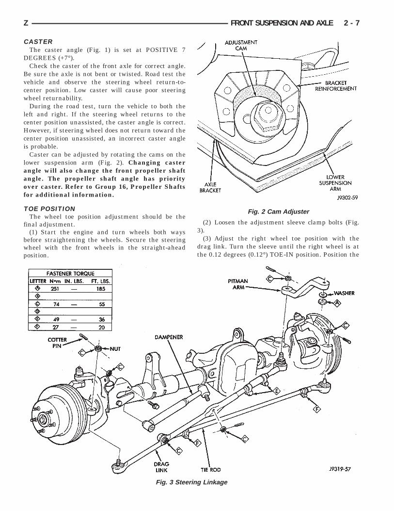
Caster can be adjusted by rotating the cams on thelower suspension arm (Fig. 2). Changing casterangle will also change the front propeller shaftangle. The propeller shaft angle has priorityover caster. Refer to Group 16, Propeller Shaftsfor additional information.
TOE POSITIONThe wheel toe position adjustment should be the
final adjustment.(1) Start the engine and turn wheels both ways
before straightening the wheels. Secure the steeringwheel with the front wheels in the straight-aheadposition.
(2) Loosen the adjustment sleeve clamp bolts (Fig.3).
(3) Adjust the right wheel toe position with thedrag link. Turn the sleeve until the right wheel is atthe 0.12 degrees (0.12°) TOE-IN position. Position the
Fig. 2 Cam Adjuster
Fig. 3 Steering Linkage
Z FRONT SUSPENSION AND AXLE 2 - 7
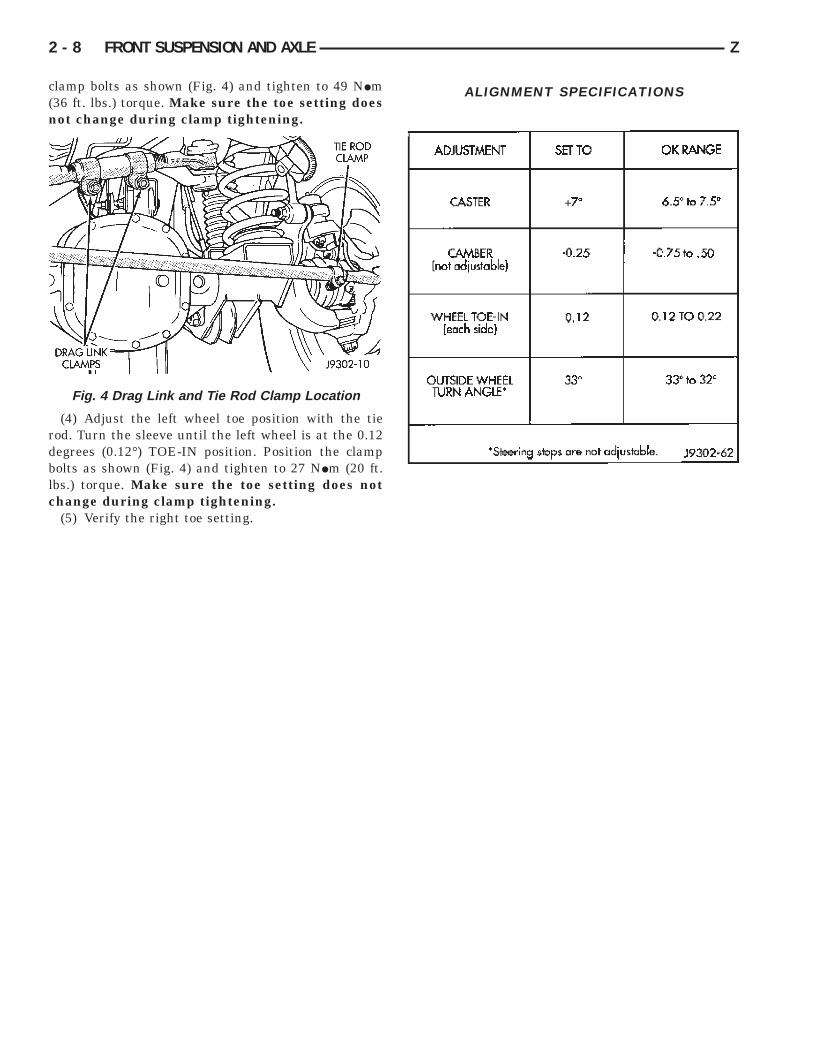
clamp bolts as shown (Fig. 4) and tighten to 49 NIm(36 ft. lbs.) torque. Make sure the toe setting doesnot change during clamp tightening.
(4) Adjust the left wheel toe position with the tierod. Turn the sleeve until the left wheel is at the 0.12degrees (0.12°) TOE-IN position. Position the clampbolts as shown (Fig. 4) and tighten to 27 NIm (20 ft.lbs.) torque. Make sure the toe setting does notchange during clamp tightening.
(5) Verify the right toe setting.
ALIGNMENT SPECIFICATIONS
Fig. 4 Drag Link and Tie Rod Clamp Location
2 - 8 FRONT SUSPENSION AND AXLE Z
FRONT SUSPENSION
INDEX
page page
Axle Bushing Replacement . . . . . . . . . . . . . . . . . . 10Coil Spring . . . . . . . . . . . . . . . . . . . . . . . . . . . . . . 12Lower Suspension Arm . . . . . . . . . . . . . . . . . . . . . 11Service Information . . . . . . . . . . . . . . . . . . . . . . . . 9Shock Absorber . . . . . . . . . . . . . . . . . . . . . . . . . . 12
Spring and Shock Diagnosis . . . . . . . . . . . . . . . . . 11Stabilizer Bar . . . . . . . . . . . . . . . . . . . . . . . . . . . . . 9Track Bar . . . . . . . . . . . . . . . . . . . . . . . . . . . . . . . 9Upper Suspension Arm . . . . . . . . . . . . . . . . . . . . 10
SERVICE INFORMATION
CAUTION: All suspension components that use rub-ber bushings should be tightened with the vehicle atthe normal height. It is important to have the springssupporting the weight of the vehicle when the fas-teners are torqued. If the springs are not at theirnormal ride position, vehicle ride comfort could beaffected. Rubber bushings must never be lubricated.
TRACK BAR
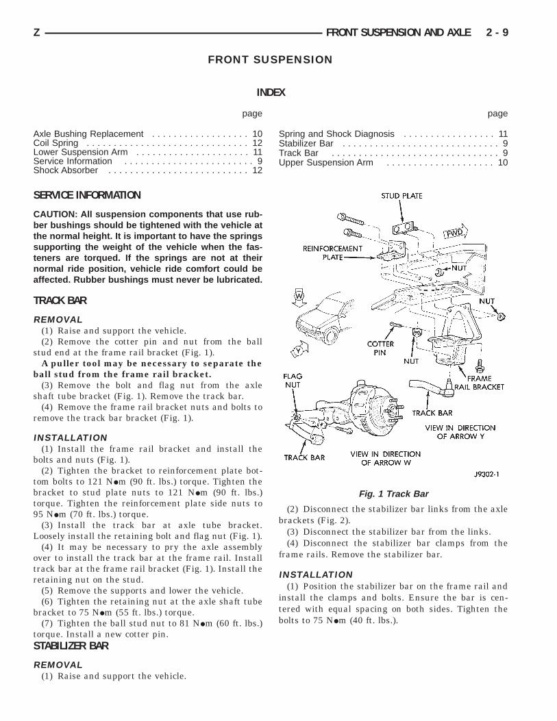
REMOVAL(1) Raise and support the vehicle.(2) Remove the cotter pin and nut from the ball
stud end at the frame rail bracket (Fig. 1).A puller tool may be necessary to separate the
ball stud from the frame rail bracket.(3) Remove the bolt and flag nut from the axle
shaft tube bracket (Fig. 1). Remove the track bar.(4) Remove the frame rail bracket nuts and bolts to
remove the track bar bracket (Fig. 1).
INSTALLATION(1) Install the frame rail bracket and install the
bolts and nuts (Fig. 1).(2) Tighten the bracket to reinforcement plate bot-
tom bolts to 121 NIm (90 ft. lbs.) torque. Tighten thebracket to stud plate nuts to 121 NIm (90 ft. lbs.)torque. Tighten the reinforcement plate side nuts to95 NIm (70 ft. lbs.) torque.
(3) Install the track bar at axle tube bracket.Loosely install the retaining bolt and flag nut (Fig. 1).
(4) It may be necessary to pry the axle assemblyover to install the track bar at the frame rail. Installtrack bar at the frame rail bracket (Fig. 1). Install theretaining nut on the stud.
(5) Remove the supports and lower the vehicle.(6) Tighten the retaining nut at the axle shaft tube
bracket to 75 NIm (55 ft. lbs.) torque.(7) Tighten the ball stud nut to 81 NIm (60 ft. lbs.)
torque. Install a new cotter pin.STABILIZER BAR
REMOVAL(1) Raise and support the vehicle.
(2) Disconnect the stabilizer bar links from the axlebrackets (Fig. 2).
(3) Disconnect the stabilizer bar from the links.(4) Disconnect the stabilizer bar clamps from the
frame rails. Remove the stabilizer bar.
INSTALLATION(1) Position the stabilizer bar on the frame rail and
install the clamps and bolts. Ensure the bar is cen-tered with equal spacing on both sides. Tighten thebolts to 75 NIm (40 ft. lbs.).
Fig. 1 Track Bar
Z FRONT SUSPENSION AND AXLE 2 - 9
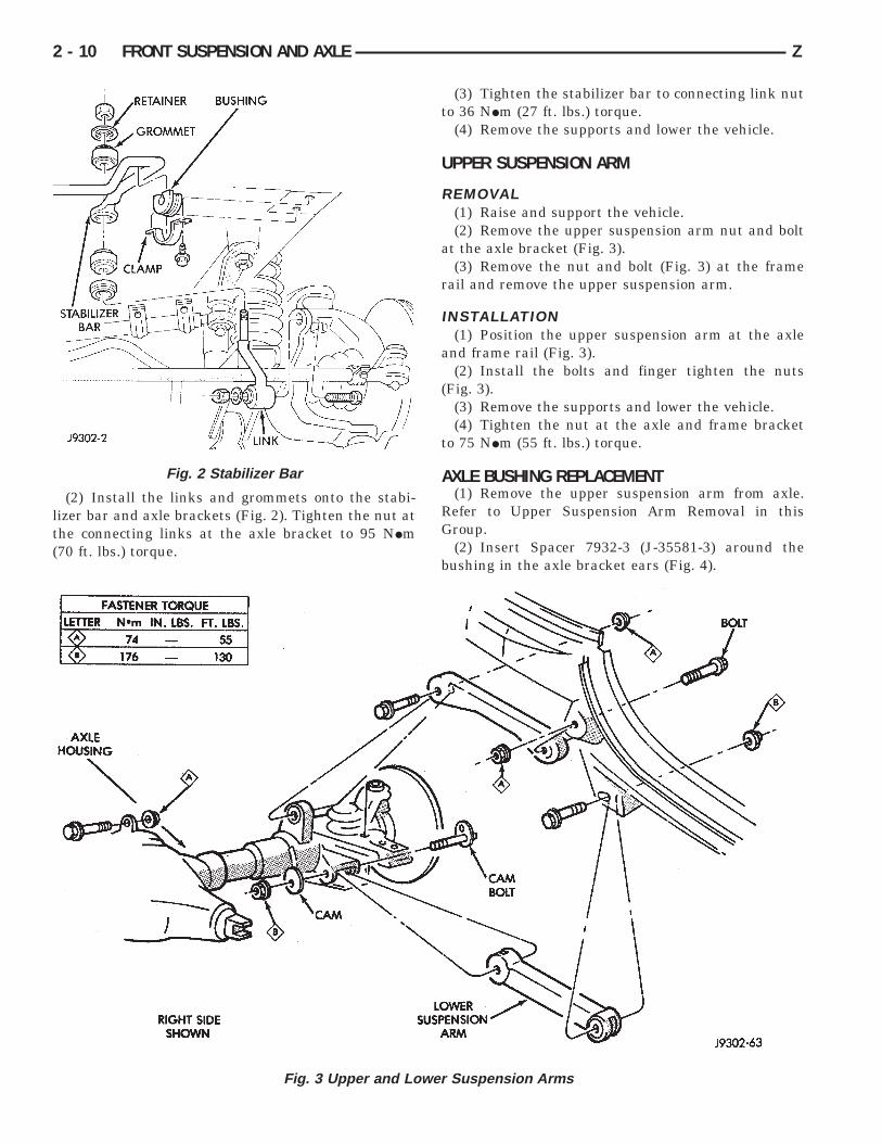
(2) Install the links and grommets onto the stabi-lizer bar and axle brackets (Fig. 2). Tighten the nut atthe connecting links at the axle bracket to 95 NIm(70 ft. lbs.) torque.
(3) Tighten the stabilizer bar to connecting link nutto 36 NIm (27 ft. lbs.) torque.
(4) Remove the supports and lower the vehicle.
UPPER SUSPENSION ARM
REMOVAL(1) Raise and support the vehicle.(2) Remove the upper suspension arm nut and bolt
at the axle bracket (Fig. 3).(3) Remove the nut and bolt (Fig. 3) at the frame
rail and remove the upper suspension arm.
INSTALLATION(1) Position the upper suspension arm at the axle
and frame rail (Fig. 3).(2) Install the bolts and finger tighten the nuts
(Fig. 3).(3) Remove the supports and lower the vehicle.(4) Tighten the nut at the axle and frame bracket
to 75 NIm (55 ft. lbs.) torque.
AXLE BUSHING REPLACEMENT(1) Remove the upper suspension arm from axle.
Refer to Upper Suspension Arm Removal in thisGroup.
(2) Insert Spacer 7932-3 (J-35581-3) around thebushing in the axle bracket ears (Fig. 4).
Fig. 2 Stabilizer Bar
Fig. 3 Upper and Lower Suspension Arms
2 - 10 FRONT SUSPENSION AND AXLE Z
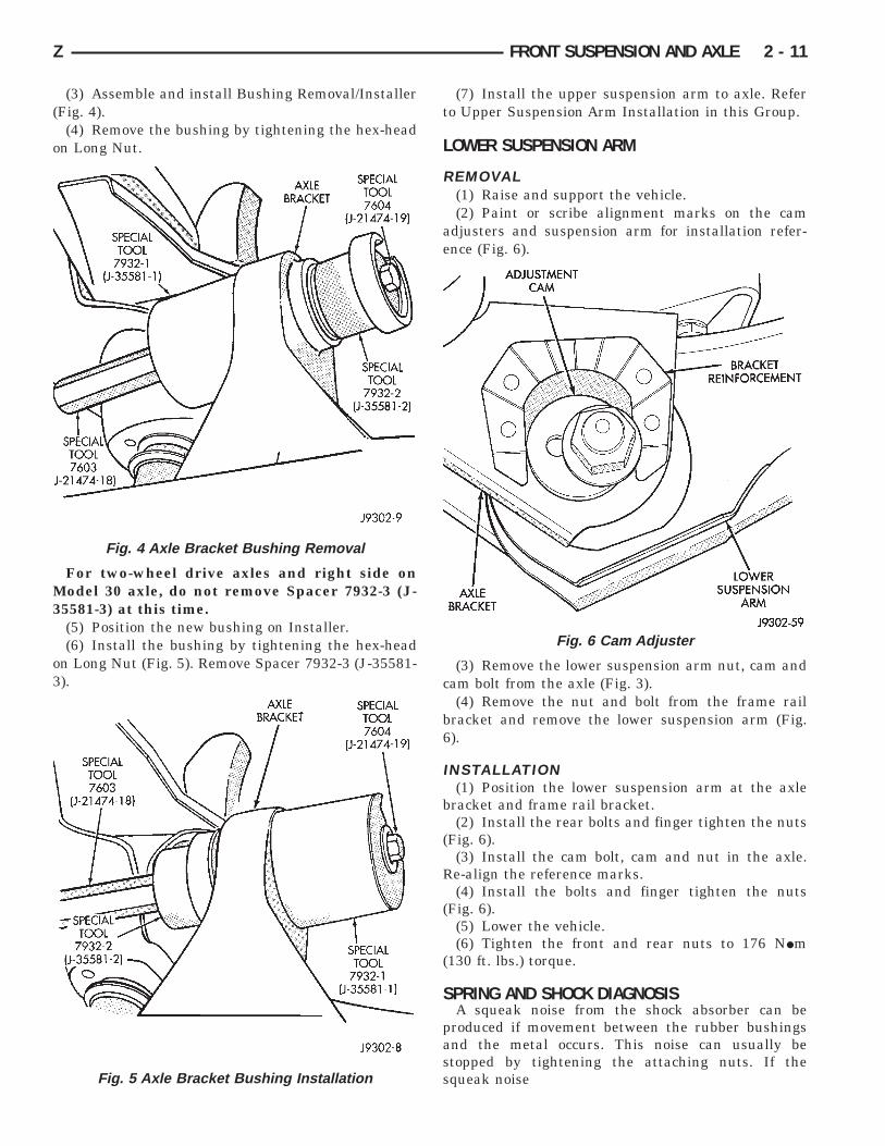
(3) Assemble and install Bushing Removal/Installer(Fig. 4).
(4) Remove the bushing by tightening the hex-headon Long Nut.
For two-wheel drive axles and right side onModel 30 axle, do not remove Spacer 7932-3 (J-35581-3) at this time.
(5) Position the new bushing on Installer.(6) Install the bushing by tightening the hex-head
on Long Nut (Fig. 5). Remove Spacer 7932-3 (J-35581-3).
(7) Install the upper suspension arm to axle. Referto Upper Suspension Arm Installation in this Group.
LOWER SUSPENSION ARM
REMOVAL(1) Raise and support the vehicle.(2) Paint or scribe alignment marks on the cam
adjusters and suspension arm for installation refer-ence (Fig. 6).
(3) Remove the lower suspension arm nut, cam andcam bolt from the axle (Fig. 3).
(4) Remove the nut and bolt from the frame railbracket and remove the lower suspension arm (Fig.6).
INSTALLATION(1) Position the lower suspension arm at the axle
bracket and frame rail bracket.(2) Install the rear bolts and finger tighten the nuts
(Fig. 6).(3) Install the cam bolt, cam and nut in the axle.
Re-align the reference marks.(4) Install the bolts and finger tighten the nuts
(Fig. 6).(5) Lower the vehicle.(6) Tighten the front and rear nuts to 176 NIm
(130 ft. lbs.) torque.
SPRING AND SHOCK DIAGNOSISA squeak noise from the shock absorber can be
produced if movement between the rubber bushingsand the metal occurs. This noise can usually bestopped by tightening the attaching nuts. If thesqueak noise
Fig. 4 Axle Bracket Bushing Removal
Fig. 5 Axle Bracket Bushing Installation
Fig. 6 Cam Adjuster
Z FRONT SUSPENSION AND AXLE 2 - 11
persists, inspect for damaged and worn bushings, andattaching components. Repair as necessary if any ofthese conditions exist.
The shock absorbers are not refillable or adjustable.If a malfunction occurs, the shock absorber must bereplaced. To test a shock absorber, hold it in an up-right position and force the piston into and out of thecylinder four or five times. The action throughouteach stroke should be smooth and even.
SHOCK ABSORBER
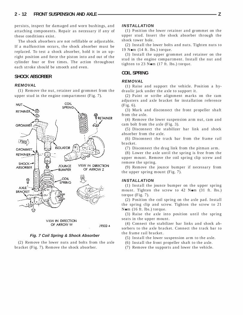
REMOVAL(1) Remove the nut, retainer and grommet from the
upper stud in the engine compartment (Fig. 7).
(2) Remove the lower nuts and bolts from the axlebracket (Fig. 7). Remove the shock absorber.
INSTALLATION(1) Position the lower retainer and grommet on the
upper stud. Insert the shock absorber through theshock tower hole.
(2) Install the lower bolts and nuts. Tighten nuts to19 NIm (14 ft. lbs.) torque.
(3) Install the upper grommet and retainer on thestud in the engine compartment. Install the nut andtighten to 23 NIm (17 ft. lbs.) torque.
COIL SPRING
REMOVAL(1) Raise and support the vehicle. Position a hy-
draulic jack under the axle to support it.(2) Paint or scribe alignment marks on the cam
adjusters and axle bracket for installation reference(Fig. 6).
(3) Mark and disconnect the front propeller shaftfrom the axle.
(4) Remove the lower suspension arm nut, cam andcam bolt from the axle (Fig. 3).
(5) Disconnect the stabilizer bar link and shockabsorber from the axle.
(6) Disconnect the track bar from the frame railbracket.
(7) Disconnect the drag link from the pitman arm.(8) Lower the axle until the spring is free from the
upper mount. Remove the coil spring clip screw andremove the spring.
(9) Remove the jounce bumper if necessary fromthe upper spring mount (Fig. 7).
INSTALLATION(1) Install the jounce bumper on the upper spring
mount. Tighten the screw to 42 NIm (31 ft. lbs.)torque (Fig. 7).
(2) Position the coil spring on the axle pad. Installthe spring clip and screw. Tighten the screw to 21NIm (16 ft. lbs.) torque.
(3) Raise the axle into position until the springseats in the upper mount.
(4) Connect the stabilizer bar links and shock ab-sorbers to the axle bracket. Connect the track bar tothe frame rail bracket.
(5) Install the lower suspension arm to the axle.(6) Install the front propeller shaft to the axle.(7) Remove the supports and lower the vehicle.
Fig. 7 Coil Spring & Shock Absorber
2 - 12 FRONT SUSPENSION AND AXLE Z
AXLE NOISE/VIBRATION DIAGNOSIS
INDEX
page page
Driveline Snap . . . . . . . . . . . . . . . . . . . . . . . . . . . 14Gear and Bearing Noise . . . . . . . . . . . . . . . . . . . . 13General Information . . . . . . . . . . . . . . . . . . . . . . . 13
Low Speed Knock . . . . . . . . . . . . . . . . . . . . . . . . 14Vibration . . . . . . . . . . . . . . . . . . . . . . . . . . . . . . . 14
GENERAL INFORMATIONAxle bearing problem conditions are usually caused
by:• Insufficient or incorrect lubricant• Foreign matter/water contamination• Incorrect bearing preload torque adjustment
When serviced, the bearings must be cleaned thor-oughly. They should be dried with lint-free shop tow-els. Never dry bearings with compressed air.This will overheat them and brinell the bearingsurfaces. This will result in noisy operation af-ter repair.
Axle gear problem conditions are usually the resultof:• Insufficient lubrication• Incorrect or contaminated lubricant• Overloading (excessive engine torque)• Incorrect clearance or backlash adjustment
Insufficient lubrication is usually the result of ahousing cover leak. It can also be from worn axleshaft or pinion gear seals. Check for cracks or porousareas in the housing or tubes.
Using the wrong lubricant will cause overheatingand gear failure. Gear tooth cracking and bearingspalling are indicators of this.
Axle component breakage is most often the resultof:• Severe overloading• Insufficient lubricant• Incorrect lubricant• Improperly tightened components
Common causes of overloading is from full-throttleacceleration. Overloading happens when towingheavier-than-recommended loads. Component break-age can occur when the wheels are spun excessively.Insufficient or incorrect lubricants contribute tobreakage through overheating. Loose differential com-ponents can also cause breakage.
Incorrect bearing preload or gear backlash will notresult in component breakage. Mis-adjustment willproduce enough noise to cause service repair before afailure occurs. If a mis-adjustment condition is notcorrected, component failure can result.
GEAR AND BEARING NOISE
GEAR NOISEAxle gear noise can be caused by insufficient lubri-
cant. Incorrect backlash, tooth contact, orworn/damaged gears can cause noise.
Gear noise usually happens at a specific speedrange. The range is 30 to 40 mph, or above 50 mph.The noise can also occur during a specific type ofdriving condition. These conditions are acceleration,deceleration, coast, or constant load.
When road testing, accelerate the vehicle to thespeed range where the noise is the greatest. Shiftout-of-gear and coast through the peak-noise range. Ifthe noise stops or changes greatly, check for insuffi-cient lubricant. Incorrect ring gear backlash, or geardamage can cause noise changes.
Differential side and pinion gears can be checked byturning the vehicle. They usually do not cause noisein straight-ahead driving. These gears are loaded dur-ing vehicle turns. If noise does occur during vehicleturns, the side or pinion gears could be worn ordamaged. A worn pinion gear mate shaft can alsocause a snapping or a knocking noise.
BEARING NOISEThe axle shaft, differential and pinion gear bearings
can all produce noise when worn or damaged. Bearingnoise can be either a whining, or a growling sound.
Pinion gear bearings have a constant-pitch noise.This noise changes only with vehicle speed. Pinionbearing noise will be higher because it rotates at afaster rate. Drive the vehicle and load the differential.If bearing noise occurs the pinion rear bearing is thesource of the noise. If the bearing noise is heardduring a coast, front bearing is the source.
Worn, damaged differential bearings usually pro-duce a low pitch noise. Differential bearing noise issimilar to pinion bearing. The pitch of differentialbearing noise is also constant and varies only withvehicle speed.
Axle shaft bearings produce noise and vibrationwhen worn or damaged. The noise generally changeswhen the bearings are loaded. Road test the vehicle.Turn the vehicle sharply to the left and to the right.This will load the bearings and change the noise
Z FRONT SUSPENSION AND AXLE 2 - 13
level. Where axle bearing damage is slight, the noiseis usually not noticeable at speeds above 30 mph.
LOW SPEED KNOCKLow speed knock is generally caused by a worn
U-joint or by worn side-gear thrust washers. A wornpinion gear shaft bore will also cause low speedknock.
VIBRATIONVibration at the rear of the vehicle is usually
caused by a:• Damaged drive shaft• Missing drive shaft balance weight• Worn, out-of-balance wheels• Loose wheel lug nuts• Worn U-joint• Loose spring U-bolts• Loose/broken springs• Damaged axle shaft bearings• Loose pinion gear nut• Excessive pinion yoke run out• Bent axle shaft
Check for loose or damaged front-end componentsor engine/transmission mounts. These components
can contribute to what appears to be a rear-end vi-bration. Do not overlook engine accessories, bracketsand drive belts.
All driveline components should be examined be-fore starting any repair.
Refer to Group 22, Wheels And Tires for additionalinformation.
DRIVELINE SNAPA snap or clunk noise when the vehicle is shifted
into gear (or the clutch engaged), can be caused by:• High engine idle speed• Loose engine/transmission/transfer case mounts• Worn U-joints• Loose spring mounts• Loose pinion gear nut and yoke• Excessive ring gear backlash• Excessive differential side gear-to-case clearance
The source of a snap or a clunk noise can be deter-mined with the assistance of a helper. Raise the ve-hicle on a hoist with the wheels free to rotate.Instruct the helper to shift the transmission intogear. Listen for the noise, a mechanics stethoscope ishelpful in isolating the source of a noise.
2 - 14 FRONT SUSPENSION AND AXLE Z
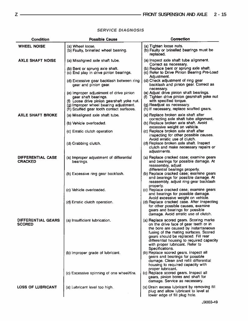
SERVICE DIAGNOSIS
Z FRONT SUSPENSION AND AXLE 2 - 15
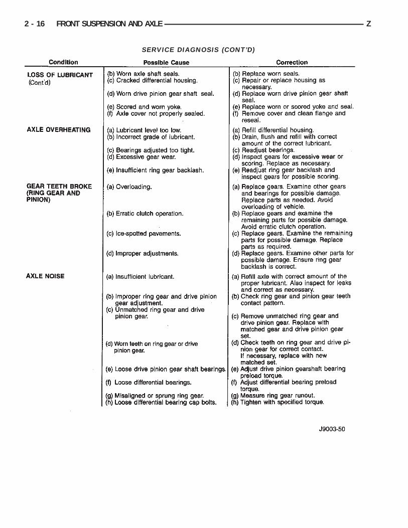
SERVICE DIAGNOSIS (CONT’D)
2 - 16 FRONT SUSPENSION AND AXLE Z
MODEL 30 AXLE AND TUBE AXLE (2WD)
INDEX
page page
Axle Bushing Replacement . . . . . . . . . . . . . . . . . . 26Axle Shaft Oil Seals . . . . . . . . . . . . . . . . . . . . . . . 27Axle Shaft— Cardan U-Joint . . . . . . . . . . . . . . . . . 20Axle Shaft— CV-Joint . . . . . . . . . . . . . . . . . . . . . . 21Axle Specifications . . . . . . . . . . . . . . . . . . . . . . . . 40Backlash and Contact Pattern Analysis . . . . . . . . . 37Cleaning/Inspection . . . . . . . . . . . . . . . . . . . . . . . 29Differential and Pinion Measurement with Gauge
Set D-115-30 . . . . . . . . . . . . . . . . . . . . . . . . . . 32Differential Assembly . . . . . . . . . . . . . . . . . . . . . . 30Differential Disassembly . . . . . . . . . . . . . . . . . . . . 27Differential Installation . . . . . . . . . . . . . . . . . . . . . 36Differential Removal . . . . . . . . . . . . . . . . . . . . . . . 26
Differential Shim Pack Measurement andAdjustment . . . . . . . . . . . . . . . . . . . . . . . . . . . . 35
Drive Axle Assembly Replacement . . . . . . . . . . . . 17Final Assembly . . . . . . . . . . . . . . . . . . . . . . . . . . 40General Information . . . . . . . . . . . . . . . . . . . . . . . 17Hub Bearing and Axle Shaft . . . . . . . . . . . . . . . . . 20Lubricant Change . . . . . . . . . . . . . . . . . . . . . . . . . 18Lubricant Specifications . . . . . . . . . . . . . . . . . . . . 17Pinion Gear Assembly/Installation . . . . . . . . . . . . . 34Pinion Gear Depth Information . . . . . . . . . . . . . . . 30Pinion Removal/Disassembly . . . . . . . . . . . . . . . . 28Pinion Shaft Seal Replacement . . . . . . . . . . . . . . 18Steering Knuckle and Ball Studs . . . . . . . . . . . . . . 25
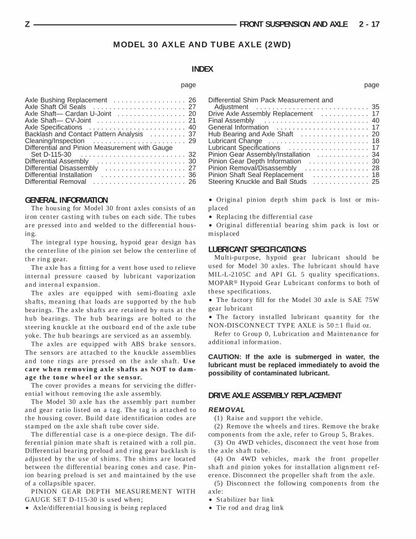
GENERAL INFORMATIONThe housing for Model 30 front axles consists of an
iron center casting with tubes on each side. The tubesare pressed into and welded to the differential hous-ing.
The integral type housing, hypoid gear design hasthe centerline of the pinion set below the centerline ofthe ring gear.
The axle has a fitting for a vent hose used to relieveinternal pressure caused by lubricant vaporizationand internal expansion.
The axles are equipped with semi-floating axleshafts, meaning that loads are supported by the hubbearings. The axle shafts are retained by nuts at thehub bearings. The hub bearings are bolted to thesteering knuckle at the outboard end of the axle tubeyoke. The hub bearings are serviced as an assembly.
The axles are equipped with ABS brake sensors.The sensors are attached to the knuckle assembliesand tone rings are pressed on the axle shaft. Usecare when removing axle shafts as NOT to dam-age the tone wheel or the sensor.
The cover provides a means for servicing the differ-ential without removing the axle assembly.
The Model 30 axle has the assembly part numberand gear ratio listed on a tag. The tag is attached tothe housing cover. Build date identification codes arestamped on the axle shaft tube cover side.
The differential case is a one-piece design. The dif-ferential pinion mate shaft is retained with a roll pin.Differential bearing preload and ring gear backlash isadjusted by the use of shims. The shims are locatedbetween the differential bearing cones and case. Pin-ion bearing preload is set and maintained by the useof a collapsible spacer.
PINION GEAR DEPTH MEASUREMENT WITHGAUGE SET D-115-30 is used when;• Axle/differential housing is being replaced
• Original pinion depth shim pack is lost or mis-placed• Replacing the differential case• Original differential bearing shim pack is lost ormisplaced
LUBRICANT SPECIFICATIONSMulti-purpose, hypoid gear lubricant should be
used for Model 30 axles. The lubricant should haveMIL-L-2105C and API GL 5 quality specifications.MOPARt Hypoid Gear Lubricant conforms to both ofthese specifications.• The factory fill for the Model 30 axle is SAE 75Wgear lubricant• The factory installed lubricant quantity for theNON-DISCONNECT TYPE AXLE is 5061 fluid oz.
Refer to Group 0, Lubrication and Maintenance foradditional information.
CAUTION: If the axle is submerged in water, thelubricant must be replaced immediately to avoid thepossibility of contaminated lubricant.
DRIVE AXLE ASSEMBLY REPLACEMENT
REMOVAL(1) Raise and support the vehicle.(2) Remove the wheels and tires. Remove the brake
components from the axle, refer to Group 5, Brakes.(3) On 4WD vehicles, disconnect the vent hose from
the axle shaft tube.(4) On 4WD vehicles, mark the front propeller
shaft and pinion yokes for installation alignment ref-erence. Disconnect the propeller shaft from the axle.
(5) Disconnect the following components from theaxle:• Stabilizer bar link• Tie rod and drag link
Z FRONT SUSPENSION AND AXLE 2 - 17
• Front propeller shaft• Shock absorbers• Steering dampener• ABS brake sensor• Track bar
(6) Position a floor jack under the axle.(7) Paint or scribe alignment marks on the lower
suspension arm cam adjusters and axle bracket forinstallation reference.
(8) Remove the lower suspension arm nut, cam andcam bolt from the axle bracket.
(9) Remove the upper suspension arm nut and boltfrom the axle.
(10) Lower the axle with the jack.
INSTALLATIONIt is important to have the springs supporting
the weight of the vehicle when the arms andfasteners are being torqued. If the springs arenot at their normal ride position, vehicle ridecomfort could be affected along with prematurerubber bushing wear.
(1) Raise the axle with a floor jack and align it withthe coil springs.
(2) Install the upper and lower suspension arms.(3) Install the lower suspension arm cam bolt, cam
and nut in the axle bracket. Re-align the referencemarks. (If installing a new axle housing assembly, afront alignment is recommended to set caster.)
(4) Install the bolts and tighten the nuts on thesuspension arms;• Lower: 176 NIm (130 ft. lbs.) torque• Upper: 75 NIm (55 ft. lbs.) torque
(5) Install the following components to the axle:• Track bar bolt — 100 NIm (74 ft. lbs.) torque• Steering dampener bolt/nut — 75 NIm (55 ft. lbs.)torque• Shock absorber bolt/nut — 19 NIm (14 ft. lbs.)torque• Stabilizer bar link nut — 95 NIm (70 ft. lbs.)torque• Drag link stud nut — 74 NIm (55 ft. lbs.) torque• Tie rod stud nut — 74 NIm (55 ft. lbs.) torque• ABS brake sensor• Axle vent hose• Front propeller shaft — 19 NIm (14 ft. lbs.) torque
(6) Install the brake components, refer to Group 5,Brakes.
(7) Install the wheels and tires.(8) Check and add gear lubricant if needed.(9) Lower the vehicle.(10) Check the front wheel alignment.
LUBRICANT CHANGEThe gear lubricant will drain quicker if the vehicle
has been recently driven.(1) Raise and support the vehicle.
(2) Remove the lubricant fill hole plug from thedifferential housing cover.
(3) Remove the differential housing cover and drainthe lubricant from the housing.
(4) Clean the housing cavity with a flushing oil,light engine oil or lint free cloth. Do not use water,steam, kerosene or gasoline for cleaning.
(5) Remove the sealant from the housing and coversurfaces. Use solvent to clean the mating surfaces.
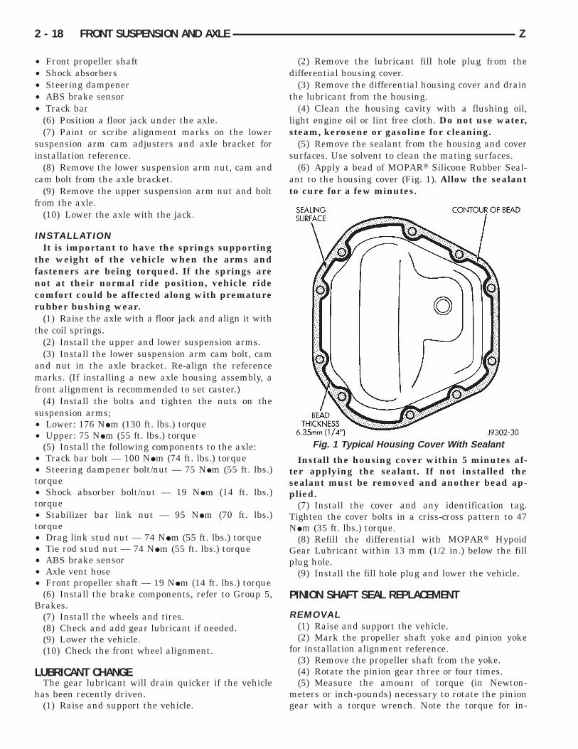
(6) Apply a bead of MOPARt Silicone Rubber Seal-ant to the housing cover (Fig. 1). Allow the sealantto cure for a few minutes.
Install the housing cover within 5 minutes af-ter applying the sealant. If not installed thesealant must be removed and another bead ap-plied.
(7) Install the cover and any identification tag.Tighten the cover bolts in a criss-cross pattern to 47NIm (35 ft. lbs.) torque.
(8) Refill the differential with MOPARt HypoidGear Lubricant within 13 mm (1/2 in.) below the fillplug hole.
(9) Install the fill hole plug and lower the vehicle.
PINION SHAFT SEAL REPLACEMENT
REMOVAL(1) Raise and support the vehicle.(2) Mark the propeller shaft yoke and pinion yoke
for installation alignment reference.(3) Remove the propeller shaft from the yoke.(4) Rotate the pinion gear three or four times.(5) Measure the amount of torque (in Newton-
meters or inch-pounds) necessary to rotate the piniongear with a torque wrench. Note the torque for in-
Fig. 1 Typical Housing Cover With Sealant
2 - 18 FRONT SUSPENSION AND AXLE Z
stallation reference. It must be known to properlyadjust the pinion gear bearing preload torqueafter seal installation.
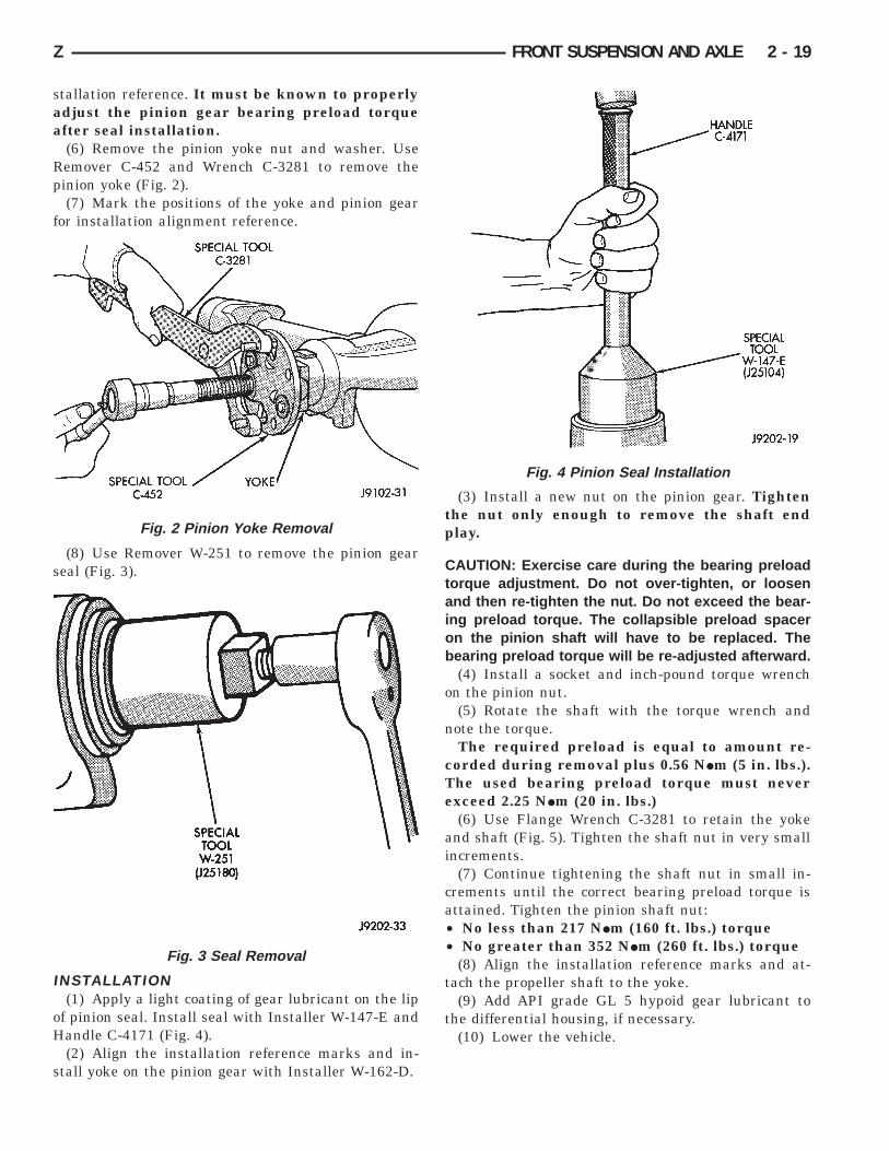
(6) Remove the pinion yoke nut and washer. UseRemover C-452 and Wrench C-3281 to remove thepinion yoke (Fig. 2).
(7) Mark the positions of the yoke and pinion gearfor installation alignment reference.
(8) Use Remover W-251 to remove the pinion gearseal (Fig. 3).
INSTALLATION(1) Apply a light coating of gear lubricant on the lip
of pinion seal. Install seal with Installer W-147-E andHandle C-4171 (Fig. 4).
(2) Align the installation reference marks and in-stall yoke on the pinion gear with Installer W-162-D.
(3) Install a new nut on the pinion gear. Tightenthe nut only enough to remove the shaft endplay.
CAUTION: Exercise care during the bearing preloadtorque adjustment. Do not over-tighten, or loosenand then re-tighten the nut. Do not exceed the bear-ing preload torque. The collapsible preload spaceron the pinion shaft will have to be replaced. Thebearing preload torque will be re-adjusted afterward.
(4) Install a socket and inch-pound torque wrenchon the pinion nut.
(5) Rotate the shaft with the torque wrench andnote the torque.
The required preload is equal to amount re-corded during removal plus 0.56 NIm (5 in. lbs.).The used bearing preload torque must neverexceed 2.25 NIm (20 in. lbs.)
(6) Use Flange Wrench C-3281 to retain the yokeand shaft (Fig. 5). Tighten the shaft nut in very smallincrements.
(7) Continue tightening the shaft nut in small in-crements until the correct bearing preload torque isattained. Tighten the pinion shaft nut:• No less than 217 NIm (160 ft. lbs.) torque• No greater than 352 NIm (260 ft. lbs.) torque
(8) Align the installation reference marks and at-tach the propeller shaft to the yoke.
(9) Add API grade GL 5 hypoid gear lubricant tothe differential housing, if necessary.
(10) Lower the vehicle.
Fig. 2 Pinion Yoke Removal
Fig. 3 Seal Removal
Fig. 4 Pinion Seal Installation
Z FRONT SUSPENSION AND AXLE 2 - 19
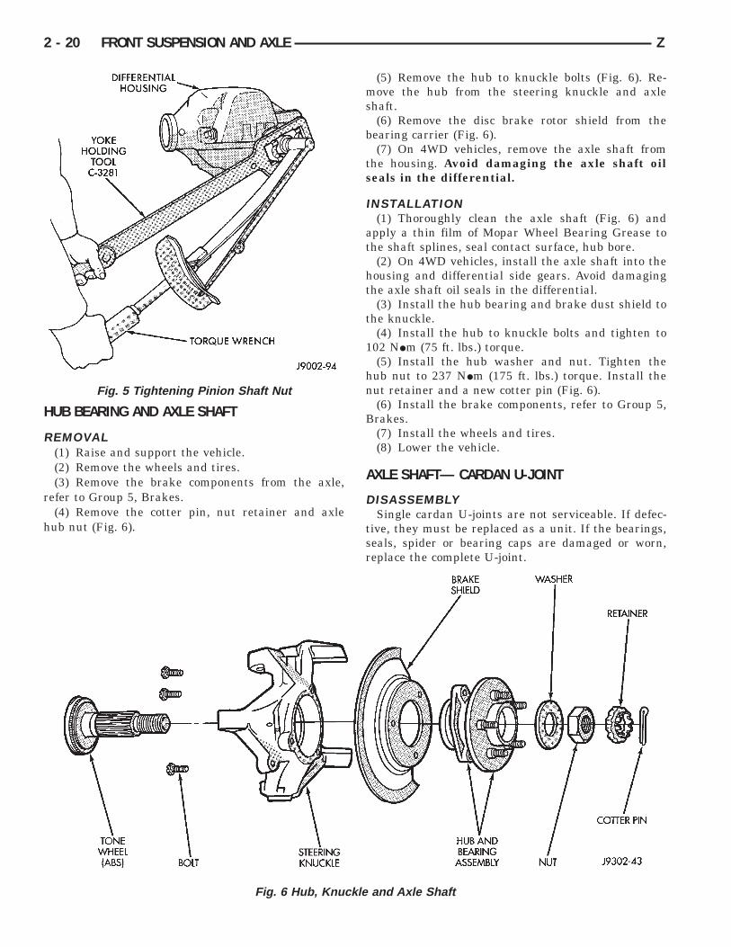
HUB BEARING AND AXLE SHAFT
REMOVAL(1) Raise and support the vehicle.(2) Remove the wheels and tires.(3) Remove the brake components from the axle,
refer to Group 5, Brakes.(4) Remove the cotter pin, nut retainer and axle
hub nut (Fig. 6).
(5) Remove the hub to knuckle bolts (Fig. 6). Re-move the hub from the steering knuckle and axleshaft.
(6) Remove the disc brake rotor shield from thebearing carrier (Fig. 6).
(7) On 4WD vehicles, remove the axle shaft fromthe housing. Avoid damaging the axle shaft oilseals in the differential.
INSTALLATION(1) Thoroughly clean the axle shaft (Fig. 6) and
apply a thin film of Mopar Wheel Bearing Grease tothe shaft splines, seal contact surface, hub bore.
(2) On 4WD vehicles, install the axle shaft into thehousing and differential side gears. Avoid damagingthe axle shaft oil seals in the differential.
(3) Install the hub bearing and brake dust shield tothe knuckle.
(4) Install the hub to knuckle bolts and tighten to102 NIm (75 ft. lbs.) torque.
(5) Install the hub washer and nut. Tighten thehub nut to 237 NIm (175 ft. lbs.) torque. Install thenut retainer and a new cotter pin (Fig. 6).
(6) Install the brake components, refer to Group 5,Brakes.
(7) Install the wheels and tires.(8) Lower the vehicle.
AXLE SHAFT— CARDAN U-JOINT
DISASSEMBLYSingle cardan U-joints are not serviceable. If defec-
tive, they must be replaced as a unit. If the bearings,seals, spider or bearing caps are damaged or worn,replace the complete U-joint.
Fig. 6 Hub, Knuckle and Axle Shaft
Fig. 5 Tightening Pinion Shaft Nut
2 - 20 FRONT SUSPENSION AND AXLE Z
CAUTION: Clamp only the forged portion of the yokein the vise. Also, to avoid distorting the yoke, do notover tighten the vise jaws.
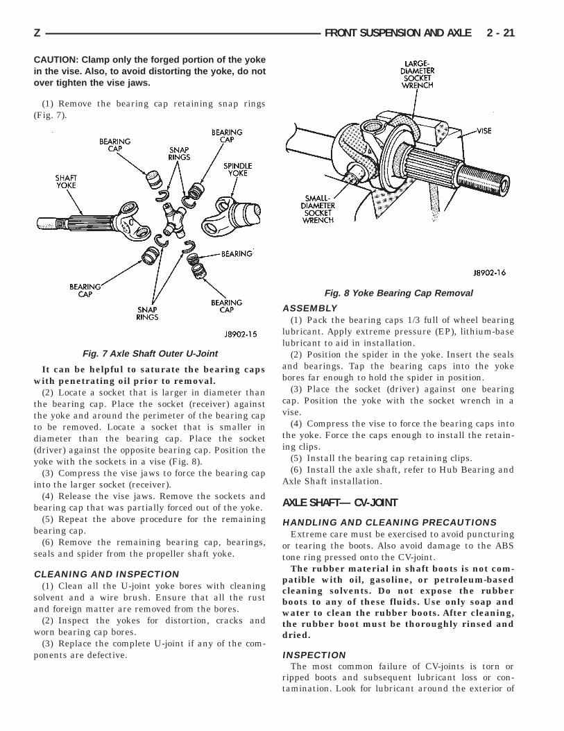
(1) Remove the bearing cap retaining snap rings(Fig. 7).
It can be helpful to saturate the bearing capswith penetrating oil prior to removal.
(2) Locate a socket that is larger in diameter thanthe bearing cap. Place the socket (receiver) againstthe yoke and around the perimeter of the bearing capto be removed. Locate a socket that is smaller indiameter than the bearing cap. Place the socket(driver) against the opposite bearing cap. Position theyoke with the sockets in a vise (Fig. 8).
(3) Compress the vise jaws to force the bearing capinto the larger socket (receiver).
(4) Release the vise jaws. Remove the sockets andbearing cap that was partially forced out of the yoke.
(5) Repeat the above procedure for the remainingbearing cap.
(6) Remove the remaining bearing cap, bearings,seals and spider from the propeller shaft yoke.
CLEANING AND INSPECTION(1) Clean all the U-joint yoke bores with cleaning
solvent and a wire brush. Ensure that all the rustand foreign matter are removed from the bores.
(2) Inspect the yokes for distortion, cracks andworn bearing cap bores.
(3) Replace the complete U-joint if any of the com-ponents are defective.
ASSEMBLY(1) Pack the bearing caps 1/3 full of wheel bearing
lubricant. Apply extreme pressure (EP), lithium-baselubricant to aid in installation.
(2) Position the spider in the yoke. Insert the sealsand bearings. Tap the bearing caps into the yokebores far enough to hold the spider in position.
(3) Place the socket (driver) against one bearingcap. Position the yoke with the socket wrench in avise.
(4) Compress the vise to force the bearing caps intothe yoke. Force the caps enough to install the retain-ing clips.
(5) Install the bearing cap retaining clips.(6) Install the axle shaft, refer to Hub Bearing and
Axle Shaft installation.
AXLE SHAFT— CV-JOINT
HANDLING AND CLEANING PRECAUTIONSExtreme care must be exercised to avoid puncturing
or tearing the boots. Also avoid damage to the ABStone ring pressed onto the CV-joint.
The rubber material in shaft boots is not com-patible with oil, gasoline, or petroleum-basedcleaning solvents. Do not expose the rubberboots to any of these fluids. Use only soap andwater to clean the rubber boots. After cleaning,the rubber boot must be thoroughly rinsed anddried.
INSPECTIONThe most common failure of CV-joints is torn or
ripped boots and subsequent lubricant loss or con-tamination. Look for lubricant around the exterior of
Fig. 7 Axle Shaft Outer U-Joint
Fig. 8 Yoke Bearing Cap Removal
Z FRONT SUSPENSION AND AXLE 2 - 21
boot. Check if boot is either punctured, torn or that aretaining clamp is loose. If joint was operating satis-factorily and grease does not appear contaminated,replace boot. When a CV drive shaft is removed fromthe vehicle for service, the boot should be properlycleaned. Inspect the boot for cracks, tears and scuffedareas on the surfaces. If any of these conditions exist,boot replacement is recommended.
If joint is noisy or worn, bypass following dis-assembly and replace entire unit and boot.
DISASSEMBLY(1) Remove retaining clamps from the outer CV
joint and discard. Slide the boot off the outer jointand down the shaft.
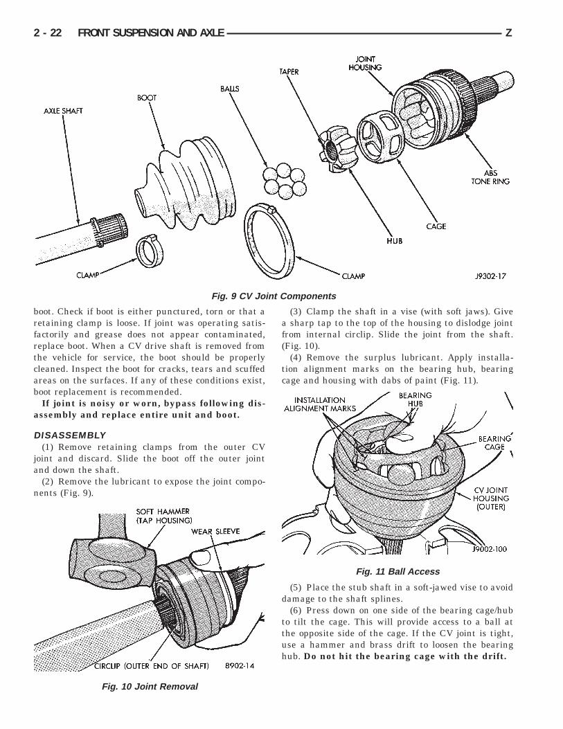
(2) Remove the lubricant to expose the joint compo-nents (Fig. 9).
(3) Clamp the shaft in a vise (with soft jaws). Givea sharp tap to the top of the housing to dislodge jointfrom internal circlip. Slide the joint from the shaft.(Fig. 10).
(4) Remove the surplus lubricant. Apply installa-tion alignment marks on the bearing hub, bearingcage and housing with dabs of paint (Fig. 11).
(5) Place the stub shaft in a soft-jawed vise to avoiddamage to the shaft splines.
(6) Press down on one side of the bearing cage/hubto tilt the cage. This will provide access to a ball atthe opposite side of the cage. If the CV joint is tight,use a hammer and brass drift to loosen the bearinghub. Do not hit the bearing cage with the drift.
Fig. 9 CV Joint Components
Fig. 10 Joint Removal
Fig. 11 Ball Access
2 - 22 FRONT SUSPENSION AND AXLE Z
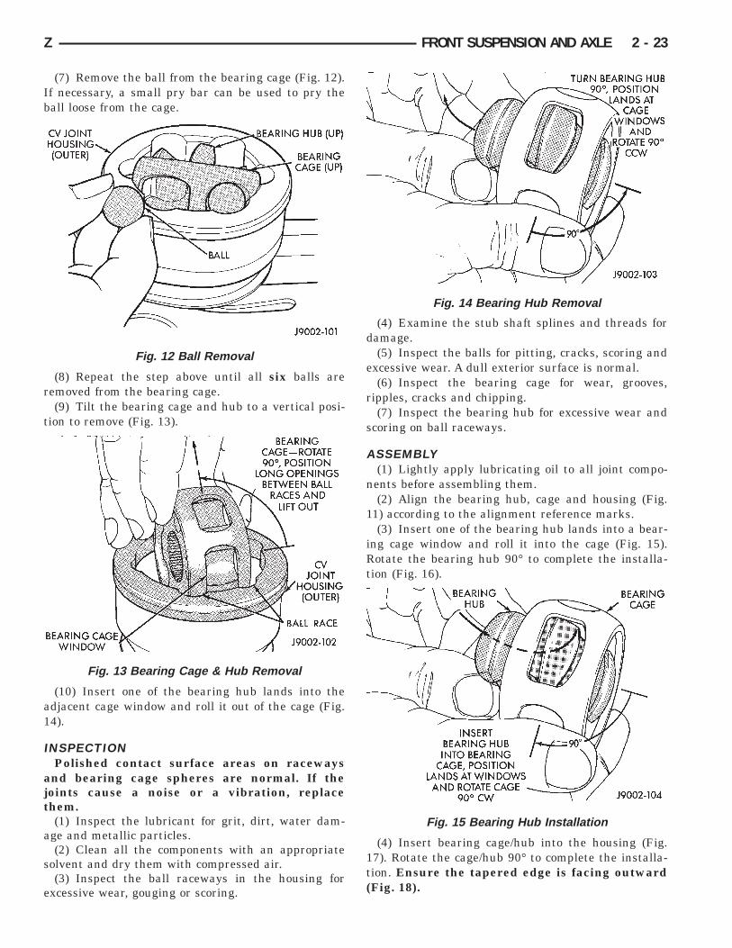
(7) Remove the ball from the bearing cage (Fig. 12).If necessary, a small pry bar can be used to pry theball loose from the cage.
(8) Repeat the step above until all six balls areremoved from the bearing cage.
(9) Tilt the bearing cage and hub to a vertical posi-tion to remove (Fig. 13).
(10) Insert one of the bearing hub lands into theadjacent cage window and roll it out of the cage (Fig.14).
INSPECTIONPolished contact surface areas on raceways
and bearing cage spheres are normal. If thejoints cause a noise or a vibration, replacethem.
(1) Inspect the lubricant for grit, dirt, water dam-age and metallic particles.
(2) Clean all the components with an appropriatesolvent and dry them with compressed air.
(3) Inspect the ball raceways in the housing forexcessive wear, gouging or scoring.
(4) Examine the stub shaft splines and threads fordamage.
(5) Inspect the balls for pitting, cracks, scoring andexcessive wear. A dull exterior surface is normal.
(6) Inspect the bearing cage for wear, grooves,ripples, cracks and chipping.
(7) Inspect the bearing hub for excessive wear andscoring on ball raceways.
ASSEMBLY(1) Lightly apply lubricating oil to all joint compo-
nents before assembling them.(2) Align the bearing hub, cage and housing (Fig.
11) according to the alignment reference marks.(3) Insert one of the bearing hub lands into a bear-
ing cage window and roll it into the cage (Fig. 15).Rotate the bearing hub 90° to complete the installa-tion (Fig. 16).
(4) Insert bearing cage/hub into the housing (Fig.17). Rotate the cage/hub 90° to complete the installa-tion. Ensure the tapered edge is facing outward(Fig. 18).
Fig. 12 Ball Removal
Fig. 13 Bearing Cage & Hub Removal
Fig. 14 Bearing Hub Removal
Fig. 15 Bearing Hub Installation
Z FRONT SUSPENSION AND AXLE 2 - 23
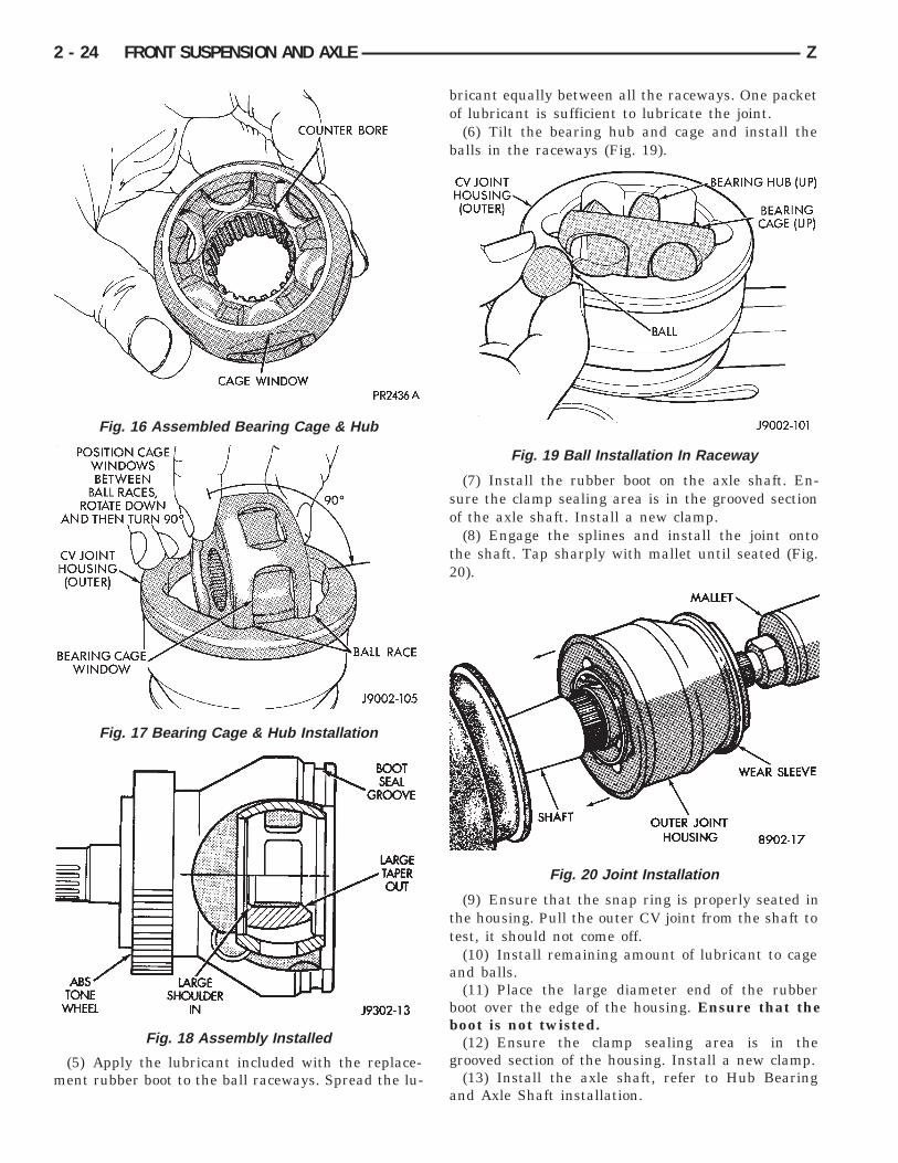
(5) Apply the lubricant included with the replace-ment rubber boot to the ball raceways. Spread the lu-
bricant equally between all the raceways. One packetof lubricant is sufficient to lubricate the joint.
(6) Tilt the bearing hub and cage and install theballs in the raceways (Fig. 19).
(7) Install the rubber boot on the axle shaft. En-sure the clamp sealing area is in the grooved sectionof the axle shaft. Install a new clamp.
(8) Engage the splines and install the joint ontothe shaft. Tap sharply with mallet until seated (Fig.20).
(9) Ensure that the snap ring is properly seated inthe housing. Pull the outer CV joint from the shaft totest, it should not come off.
(10) Install remaining amount of lubricant to cageand balls.
(11) Place the large diameter end of the rubberboot over the edge of the housing. Ensure that theboot is not twisted.
(12) Ensure the clamp sealing area is in thegrooved section of the housing. Install a new clamp.
(13) Install the axle shaft, refer to Hub Bearingand Axle Shaft installation.
Fig. 16 Assembled Bearing Cage & Hub
Fig. 17 Bearing Cage & Hub Installation
Fig. 18 Assembly Installed
Fig. 19 Ball Installation In Raceway
Fig. 20 Joint Installation
2 - 24 FRONT SUSPENSION AND AXLE Z
STEERING KNUCKLE AND BALL STUDSBall Stud service procedures below require removal
of the hub bearing and axle shaft. Removal and in-stallation of upper and lower ball stud requires useof Tool Kit 6289 (J34503-A).
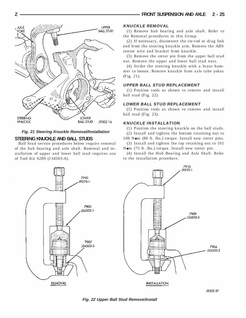
KNUCKLE REMOVAL(1) Remove hub bearing and axle shaft. Refer to
the Removal procedures in this Group.(2) If necessary, disconnect the tie-rod or drag link
end from the steering knuckle arm. Remove the ABSsensor wire and bracket from knuckle.
(3) Remove the cotter pin from the upper ball studnut. Remove the upper and lower ball stud nuts.
(4) Strike the steering knuckle with a brass ham-mer to loosen. Remove knuckle from axle tube yokes(Fig. 21).
UPPER BALL STUD REPLACEMENT(1) Position tools as shown to remove and install
ball stud (Fig. 22).
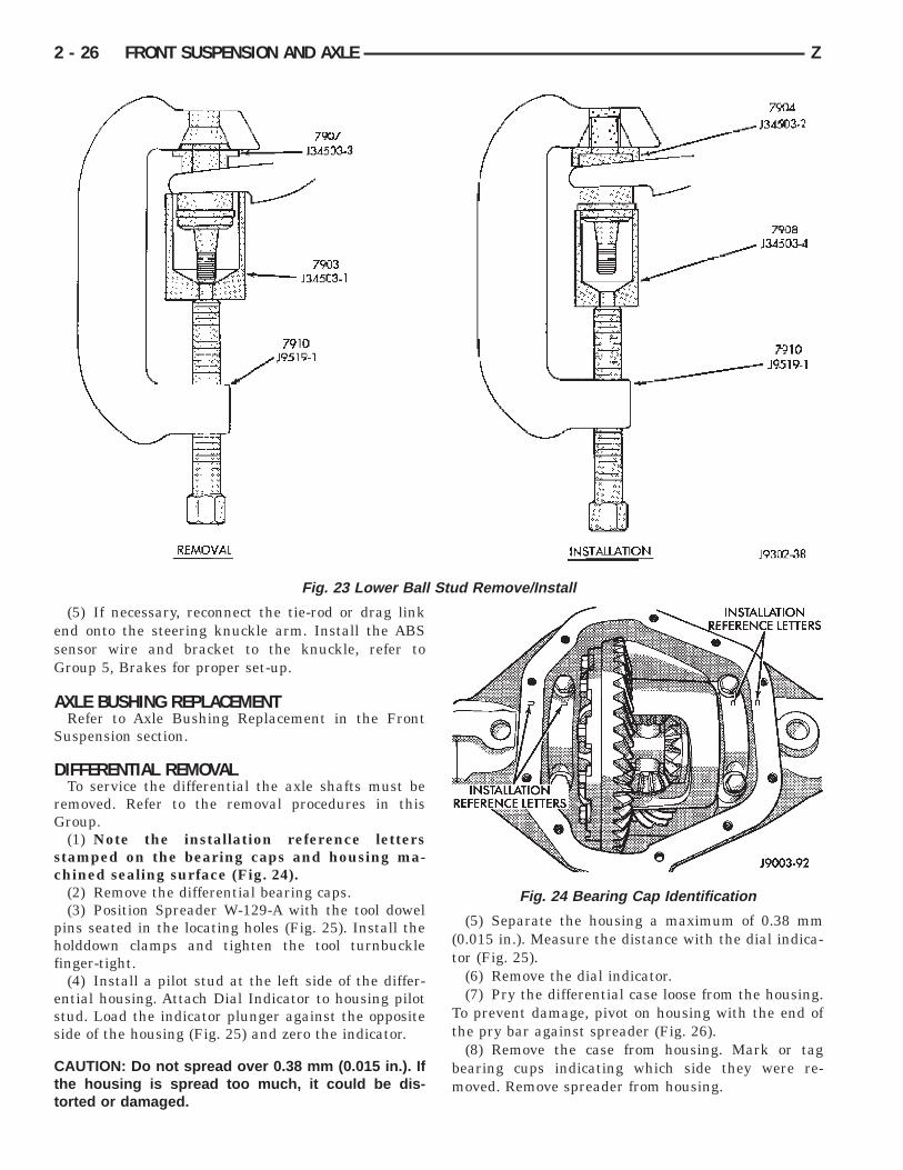
LOWER BALL STUD REPLACEMENT(1) Position tools as shown to remove and install
ball stud (Fig. 23).
KNUCKLE INSTALLATION(1) Position the steering knuckle on the ball studs.(2) Install and tighten the bottom retaining nut to
108 NIm (80 ft. lbs.) torque. Install new cotter pins.(3) Install and tighten the top retaining nut to 101
NIm (75 ft. lbs.) torque. Install new cotter pin.(4) Install the Hub Bearing and Axle Shaft. Refer
to the installation procedure.
Fig. 21 Steering Knuckle Removal/Installation
Fig. 22 Upper Ball Stud Remove/Install
Z FRONT SUSPENSION AND AXLE 2 - 25
(5) If necessary, reconnect the tie-rod or drag linkend onto the steering knuckle arm. Install the ABSsensor wire and bracket to the knuckle, refer toGroup 5, Brakes for proper set-up.
AXLE BUSHING REPLACEMENTRefer to Axle Bushing Replacement in the Front
Suspension section.
DIFFERENTIAL REMOVALTo service the differential the axle shafts must be
removed. Refer to the removal procedures in thisGroup.
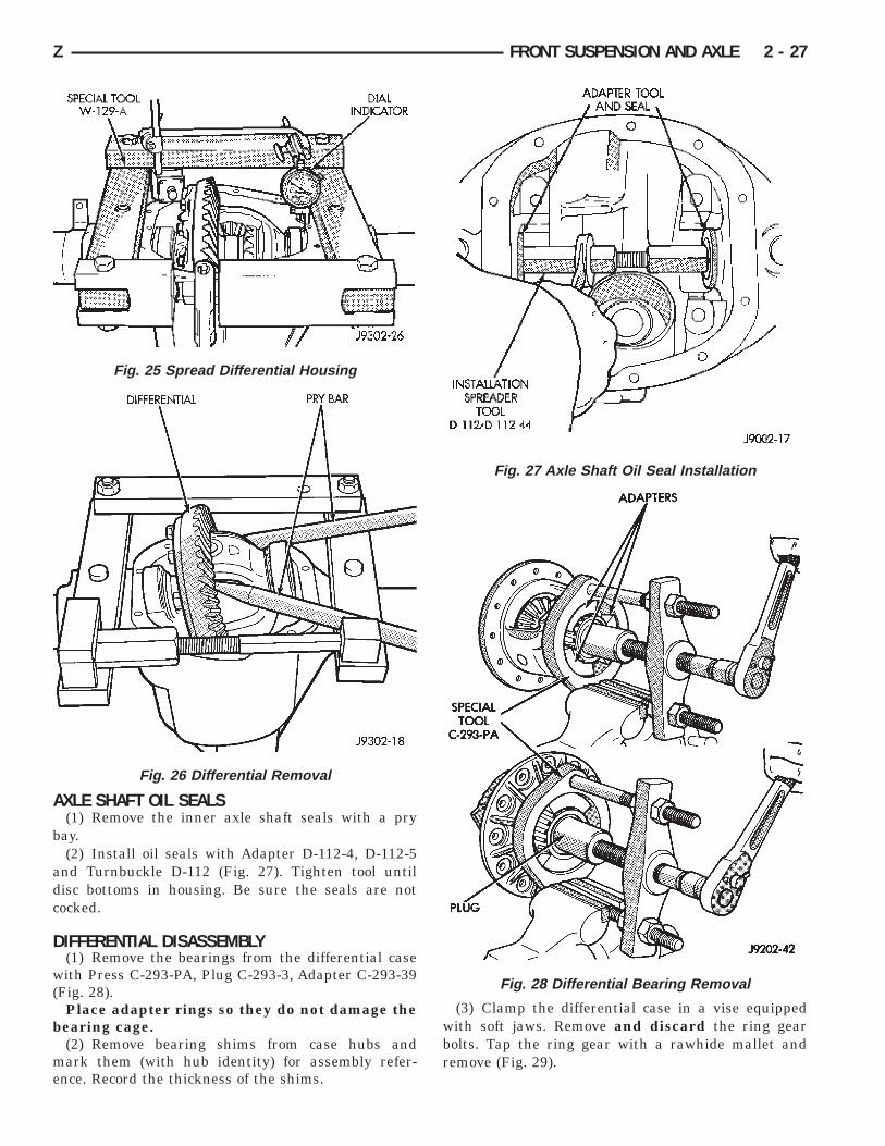
(1) Note the installation reference lettersstamped on the bearing caps and housing ma-chined sealing surface (Fig. 24).
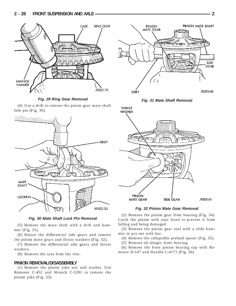
(2) Remove the differential bearing caps.(3) Position Spreader W-129-A with the tool dowel
pins seated in the locating holes (Fig. 25). Install theholddown clamps and tighten the tool turnbucklefinger-tight.
(4) Install a pilot stud at the left side of the differ-ential housing. Attach Dial Indicator to housing pilotstud. Load the indicator plunger against the oppositeside of the housing (Fig. 25) and zero the indicator.
CAUTION: Do not spread over 0.38 mm (0.015 in.). Ifthe housing is spread too much, it could be dis-torted or damaged.
(5) Separate the housing a maximum of 0.38 mm(0.015 in.). Measure the distance with the dial indica-tor (Fig. 25).
(6) Remove the dial indicator.(7) Pry the differential case loose from the housing.
To prevent damage, pivot on housing with the end ofthe pry bar against spreader (Fig. 26).
(8) Remove the case from housing. Mark or tagbearing cups indicating which side they were re-moved. Remove spreader from housing.
Fig. 23 Lower Ball Stud Remove/Install
Fig. 24 Bearing Cap Identification
2 - 26 FRONT SUSPENSION AND AXLE Z
AXLE SHAFT OIL SEALS(1) Remove the inner axle shaft seals with a pry
bay.(2) Install oil seals with Adapter D-112-4, D-112-5
and Turnbuckle D-112 (Fig. 27). Tighten tool untildisc bottoms in housing. Be sure the seals are notcocked.
DIFFERENTIAL DISASSEMBLY(1) Remove the bearings from the differential case
with Press C-293-PA, Plug C-293-3, Adapter C-293-39(Fig. 28).
Place adapter rings so they do not damage thebearing cage.
(2) Remove bearing shims from case hubs andmark them (with hub identity) for assembly refer-ence. Record the thickness of the shims.
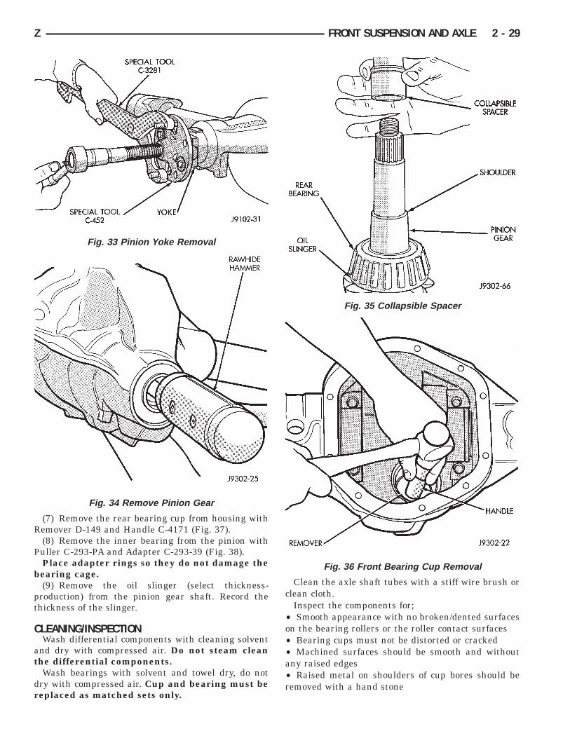
(3) Clamp the differential case in a vise equippedwith soft jaws. Remove and discard the ring gearbolts. Tap the ring gear with a rawhide mallet andremove (Fig. 29).
Fig. 25 Spread Differential Housing
Fig. 26 Differential Removal
Fig. 27 Axle Shaft Oil Seal Installation
Fig. 28 Differential Bearing Removal
Z FRONT SUSPENSION AND AXLE 2 - 27
(4) Use a drift to remove the pinion gear mate shaftlock pin (Fig. 30).
(5) Remove the mate shaft with a drift and ham-mer (Fig. 31).
(6) Rotate the differential side gears and removethe pinion mate gears and thrust washers (Fig. 32).
(7) Remove the differential side gears and thrustwashers.
(8) Remove the case from the vise.
PINION REMOVAL/DISASSEMBLY(1) Remove the pinion yoke nut and washer. Use
Remover C-452 and Wrench C-3281 to remove thepinion yoke (Fig. 33).
(2) Remove the pinion gear from housing (Fig. 34).Catch the pinion with your hand to prevent it fromfalling and being damaged.
(3) Remove the pinion gear seal with a slide ham-mer or pry out with bar.
(4) Remove the collapsible preload spacer (Fig. 35).(5) Remove oil slinger, front bearing.(6) Remove the front pinion bearing cup with Re-
mover D-147 and Handle C-4171 (Fig. 36).
Fig. 29 Ring Gear Removal
Fig. 30 Mate Shaft Lock Pin Removal
Fig. 31 Mate Shaft Removal
Fig. 32 Pinion Mate Gear Removal
2 - 28 FRONT SUSPENSION AND AXLE Z
(7) Remove the rear bearing cup from housing withRemover D-149 and Handle C-4171 (Fig. 37).
(8) Remove the inner bearing from the pinion withPuller C-293-PA and Adapter C-293-39 (Fig. 38).
Place adapter rings so they do not damage thebearing cage.
(9) Remove the oil slinger (select thickness-production) from the pinion gear shaft. Record thethickness of the slinger.
CLEANING/INSPECTIONWash differential components with cleaning solvent
and dry with compressed air. Do not steam cleanthe differential components.
Wash bearings with solvent and towel dry, do notdry with compressed air. Cup and bearing must bereplaced as matched sets only.
Clean the axle shaft tubes with a stiff wire brush orclean cloth.
Inspect the components for;• Smooth appearance with no broken/dented surfaceson the bearing rollers or the roller contact surfaces• Bearing cups must not be distorted or cracked• Machined surfaces should be smooth and withoutany raised edges• Raised metal on shoulders of cup bores should beremoved with a hand stone
Fig. 33 Pinion Yoke Removal
Fig. 34 Remove Pinion Gear
Fig. 35 Collapsible Spacer
Fig. 36 Front Bearing Cup Removal
Z FRONT SUSPENSION AND AXLE 2 - 29
• Wear and damage to pinion gear mate shaft, piniongears, side gears and thrust washers. Replace as amatched set only.• Ring and pinion gear for worn and chipped teeth• Ring gear for damaged bolt threads. Replaced as amatched set only.• Pinion yoke for cracks, worn splines, pitted areas,and a rough/corroded seal contact surface. Repair orreplace as necessary.• Preload shims for damage and distortion. Installnew shims if necessary.
DIFFERENTIAL ASSEMBLY(1) Install the following components in the differen-
tial case.• Differential side gears and thrust washers• Pinion gears and thrust washers• Pinion gear mate shaft (align holes in shaft andcase)
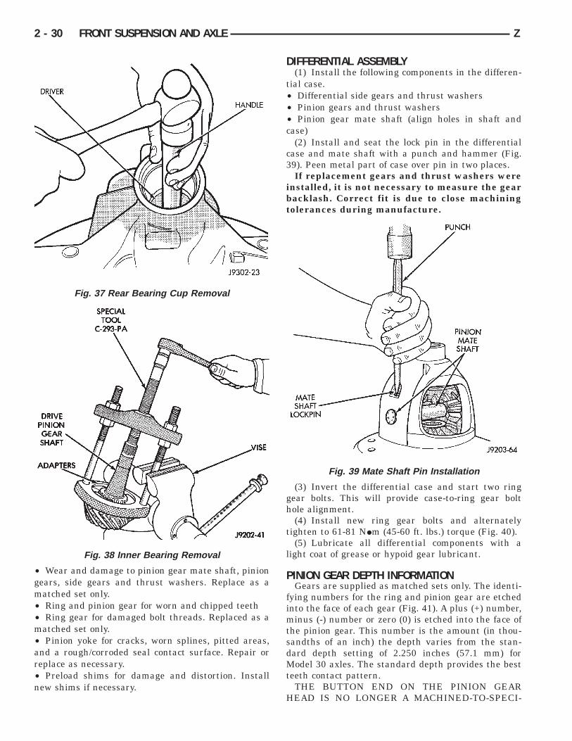
(2) Install and seat the lock pin in the differentialcase and mate shaft with a punch and hammer (Fig.39). Peen metal part of case over pin in two places.
If replacement gears and thrust washers wereinstalled, it is not necessary to measure the gearbacklash. Correct fit is due to close machiningtolerances during manufacture.
(3) Invert the differential case and start two ringgear bolts. This will provide case-to-ring gear bolthole alignment.
(4) Install new ring gear bolts and alternatelytighten to 61-81 NIm (45-60 ft. lbs.) torque (Fig. 40).
(5) Lubricate all differential components with alight coat of grease or hypoid gear lubricant.
PINION GEAR DEPTH INFORMATIONGears are supplied as matched sets only. The identi-
fying numbers for the ring and pinion gear are etchedinto the face of each gear (Fig. 41). A plus (+) number,minus (-) number or zero (0) is etched into the face ofthe pinion gear. This number is the amount (in thou-sandths of an inch) the depth varies from the stan-dard depth setting of 2.250 inches (57.1 mm) forModel 30 axles. The standard depth provides the bestteeth contact pattern.
THE BUTTON END ON THE PINION GEARHEAD IS NO LONGER A MACHINED-TO-SPECI-
Fig. 37 Rear Bearing Cup Removal
Fig. 38 Inner Bearing Removal
Fig. 39 Mate Shaft Pin Installation
2 - 30 FRONT SUSPENSION AND AXLE Z
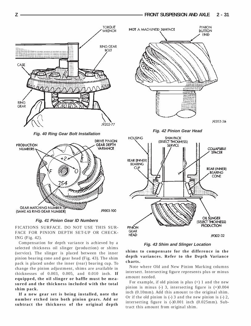
FICATIONS SURFACE. DO NOT USE THIS SUR-FACE FOR PINION DEPTH SET-UP OR CHECK-ING (Fig. 42).
Compensation for depth variance is achieved by aselected thickness oil slinger (production) or shims(service). The slinger is placed between the innerpinion bearing cone and gear head (Fig. 43). The shimpack is placed under the inner (rear) bearing cup. Tochange the pinion adjustment, shims are available inthicknesses of 0.003, 0.005, and 0.010 inch. Ifequipped, the oil slinger or baffle must be mea-sured and the thickness included with the totalshim pack.
If a new gear set is being installed, note thenumber etched into both pinion gears. Add orsubtract the thickness of the original depth
shims to compensate for the difference in thedepth variances. Refer to the Depth Variancecharts.
Note where Old and New Pinion Marking columnsintersect. Intersecting figure represents plus or minusamount needed.
For example, if old pinion is plus (+) 1 and the newpinion is minus (-) 3, intersecting figure is (+)0.004inch (0.10mm). Add this amount to the original shim.Or if the old pinion is (-) 3 and the new pinion is (-) 2,intersecting figure is (-)0.001 inch (0.025mm). Sub-tract this amount from original shim.
Fig. 40 Ring Gear Bolt Installation
Fig. 41 Pinion Gear ID Numbers
Fig. 42 Pinion Gear Head
Fig. 43 Shim and Slinger Location
Z FRONT SUSPENSION AND AXLE 2 - 31
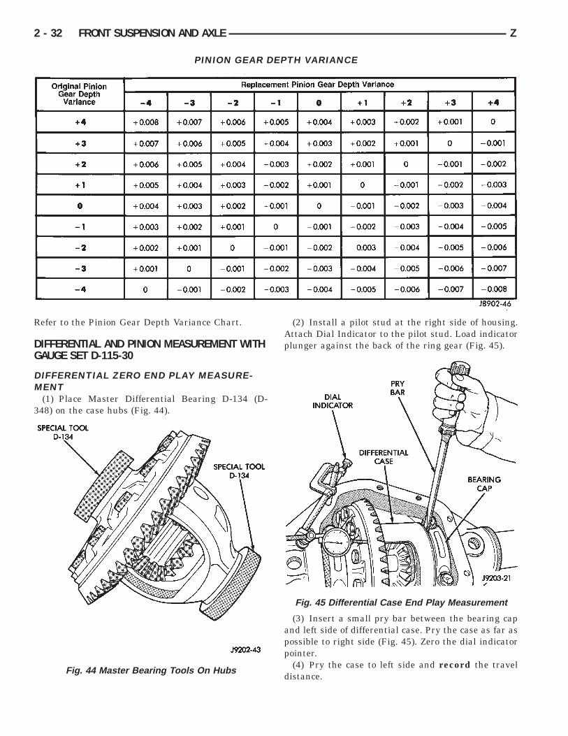
Refer to the Pinion Gear Depth Variance Chart.
DIFFERENTIAL AND PINION MEASUREMENT WITHGAUGE SET D-115-30
DIFFERENTIAL ZERO END PLAY MEASURE-MENT
(1) Place Master Differential Bearing D-134 (D-348) on the case hubs (Fig. 44).
(2) Install a pilot stud at the right side of housing.Attach Dial Indicator to the pilot stud. Load indicatorplunger against the back of the ring gear (Fig. 45).
(3) Insert a small pry bar between the bearing capand left side of differential case. Pry the case as far aspossible to right side (Fig. 45). Zero the dial indicatorpointer.
(4) Pry the case to left side and record the traveldistance.
PINION GEAR DEPTH VARIANCE
Fig. 44 Master Bearing Tools On Hubs
Fig. 45 Differential Case End Play Measurement
2 - 32 FRONT SUSPENSION AND AXLE Z
The measurement above is the shim thicknessnecessary for case zero end-play. The totalthickness will be determined during the ringgear backlash adjustment.
(5) Remove indicator and pilot stud.
PINION GEAR DEPTH MEASUREMENTThe following gear depth measurement and adjust-
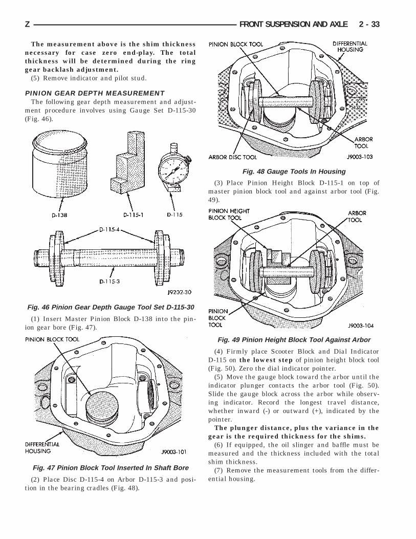
ment procedure involves using Gauge Set D-115-30(Fig. 46).
(1) Insert Master Pinion Block D-138 into the pin-ion gear bore (Fig. 47).
(2) Place Disc D-115-4 on Arbor D-115-3 and posi-tion in the bearing cradles (Fig. 48).
(3) Place Pinion Height Block D-115-1 on top ofmaster pinion block tool and against arbor tool (Fig.49).
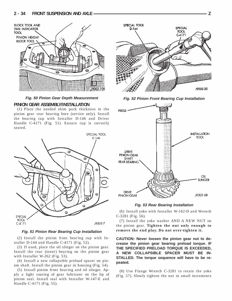
(4) Firmly place Scooter Block and Dial IndicatorD-115 on the lowest step of pinion height block tool(Fig. 50). Zero the dial indicator pointer.
(5) Move the gauge block toward the arbor until theindicator plunger contacts the arbor tool (Fig. 50).Slide the gauge block across the arbor while observ-ing indicator. Record the longest travel distance,whether inward (-) or outward (+), indicated by thepointer.
The plunger distance, plus the variance in thegear is the required thickness for the shims.
(6) If equipped, the oil slinger and baffle must bemeasured and the thickness included with the totalshim thickness.
(7) Remove the measurement tools from the differ-ential housing.
Fig. 46 Pinion Gear Depth Gauge Tool Set D-115-30
Fig. 47 Pinion Block Tool Inserted In Shaft Bore
Fig. 48 Gauge Tools In Housing
Fig. 49 Pinion Height Block Tool Against Arbor
Z FRONT SUSPENSION AND AXLE 2 - 33
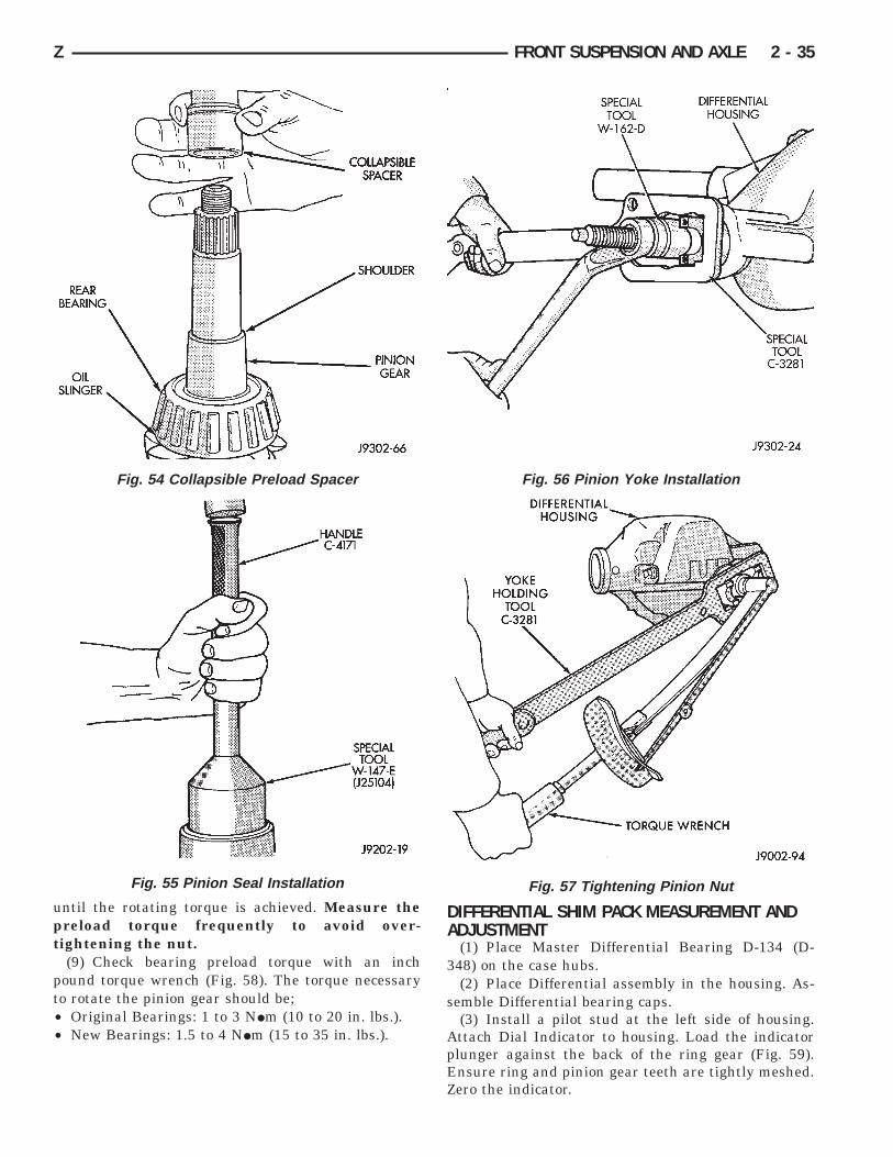
PINION GEAR ASSEMBLY/INSTALLATION(1) Place the needed shim pack thickness in the
pinion gear rear bearing bore (service only). Installthe bearing cup with Installer D-146 and DriverHandle C-4171 (Fig. 51). Ensure cup is correctlyseated.
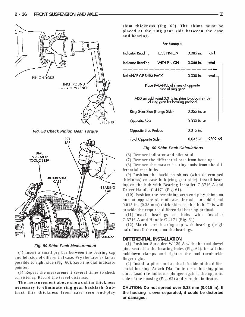
(2) Install the pinion front bearing cup with In-staller D-144 and Handle C-4171 (Fig. 52).
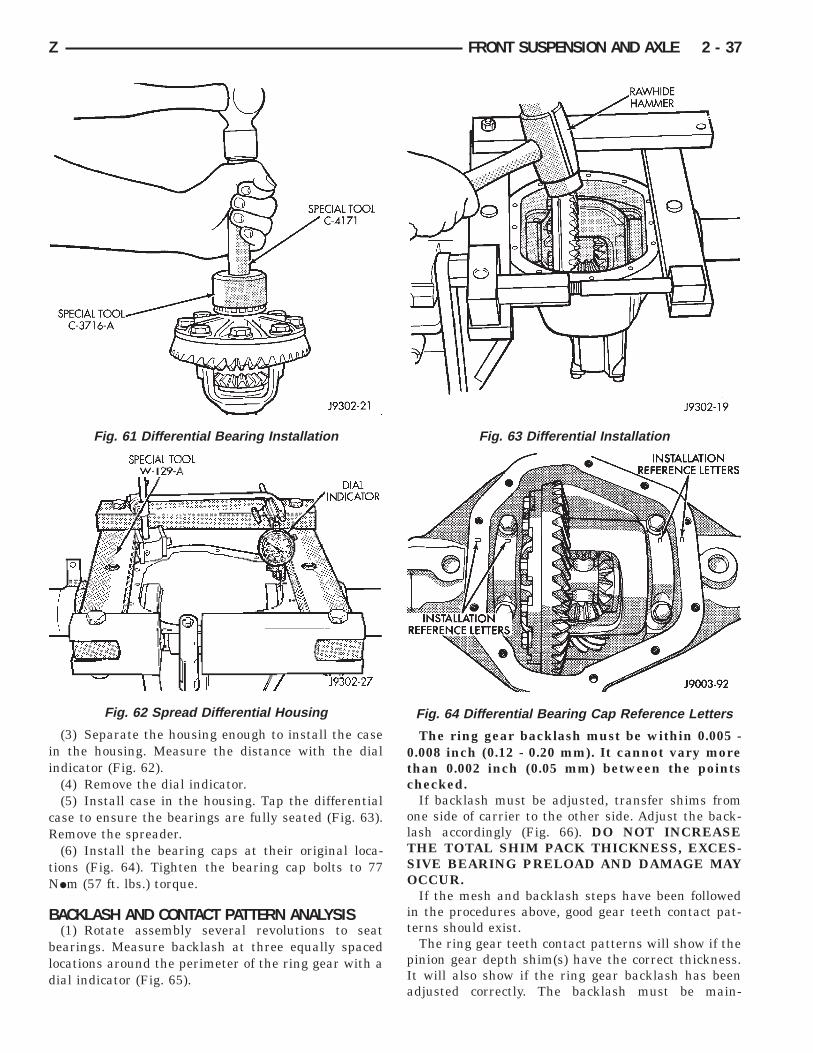
(3) If used, place the oil slinger on the pinion gear.Install the rear (inner) bearing on the pinion gearwith Installer W-262 (Fig. 53).
(4) Install a new collapsible preload spacer on pin-ion shaft. Install the pinion gear in housing (Fig. 54).
(5) Install pinion front bearing and oil slinger. Ap-ply a light coating of gear lubricant on the lip ofpinion seal. Install seal with Installer W-147-E andHandle C-4171 (Fig. 55).
(6) Install yoke with Installer W-162-D and WrenchC-3281 (Fig. 56).
(7) Install the yoke washer AND A NEW NUT onthe pinion gear. Tighten the nut only enough toremove the end play. Do not over-tighten it.
CAUTION: Never loosen the pinion gear nut to de-crease the pinion gear bearing preload torque. IFTHE SPECIFIED PRELOAD TORQUE IS EXCEEDED,A NEW COLLAPSIBLE SPACER MUST BE IN-STALLED. The torque sequence will have to be re-peated.
(8) Use Flange Wrench C-3281 to retain the yoke(Fig. 57). Slowly tighten the nut in small increments
Fig. 50 Pinion Gear Depth Measurement
Fig. 51 Pinion Rear Bearing Cup Installation
Fig. 52 Pinion Front Bearing Cup Installation
Fig. 53 Rear Bearing Installation
2 - 34 FRONT SUSPENSION AND AXLE Z
until the rotating torque is achieved. Measure thepreload torque frequently to avoid over-tightening the nut.
(9) Check bearing preload torque with an inchpound torque wrench (Fig. 58). The torque necessaryto rotate the pinion gear should be;• Original Bearings: 1 to 3 NIm (10 to 20 in. lbs.).• New Bearings: 1.5 to 4 NIm (15 to 35 in. lbs.).
DIFFERENTIAL SHIM PACK MEASUREMENT ANDADJUSTMENT
(1) Place Master Differential Bearing D-134 (D-348) on the case hubs.
(2) Place Differential assembly in the housing. As-semble Differential bearing caps.
(3) Install a pilot stud at the left side of housing.Attach Dial Indicator to housing. Load the indicatorplunger against the back of the ring gear (Fig. 59).Ensure ring and pinion gear teeth are tightly meshed.Zero the indicator.
Fig. 55 Pinion Seal Installation
Fig. 54 Collapsible Preload Spacer Fig. 56 Pinion Yoke Installation
Fig. 57 Tightening Pinion Nut
Z FRONT SUSPENSION AND AXLE 2 - 35
(4) Insert a small pry bar between the bearing capand left side of differential case. Pry the case as far aspossible to right side (Fig. 60). Zero the dial indicatorpointer.
(5) Repeat the measurement several times to checkconsistency. Record the travel distance.
The measurement above shows shim thicknessnecessary to eliminate ring gear backlash. Sub-tract this thickness from case zero end-play
shim thickness (Fig. 60). The shims must beplaced at the ring gear side between the caseand bearing.
(6) Remove indicator and pilot stud.(7) Remove the differential case from housing.(8) Remove the master bearing tools from the dif-
ferential case hubs.(9) Position the backlash shims (with determined
thickness) on case hub (ring gear side). Install bear-ing on the hub with Bearing Installer C-3716-A andDriver Handle C-4171 (Fig. 61).
(10) Position the remaining zero end-play shims onhub at opposite side of case. Include an additional0.015 in. (0.38 mm) thick shim on this hub. This willprovide the required differential bearing preload.
(11) Install bearings on hubs with InstallerC-3716-A and Handle C-4171 (Fig. 61).
(12) Match each bearing cup with bearing (origi-nal). Install the cups on the bearings.
DIFFERENTIAL INSTALLATION(1) Position Spreader W-129-A with the tool dowel
pins seated in the locating holes (Fig. 62). Install theholddown clamps and tighten the tool turnbucklefinger-tight.
(2) Install a pilot stud at the left side of the differ-ential housing. Attach Dial Indicator to housing pilotstud. Load the indicator plunger against the oppositeside of the housing (Fig. 62) and zero the indicator.
CAUTION: Do not spread over 0.38 mm (0.015 in). Ifthe housing is over-separated, it could be distortedor damaged.
Fig. 58 Check Pinion Gear Torque
Fig. 59 Shim Pack Measurement
Fig. 60 Shim Pack Calculations
2 - 36 FRONT SUSPENSION AND AXLE Z
(3) Separate the housing enough to install the casein the housing. Measure the distance with the dialindicator (Fig. 62).
(4) Remove the dial indicator.(5) Install case in the housing. Tap the differential
case to ensure the bearings are fully seated (Fig. 63).Remove the spreader.
(6) Install the bearing caps at their original loca-tions (Fig. 64). Tighten the bearing cap bolts to 77NIm (57 ft. lbs.) torque.
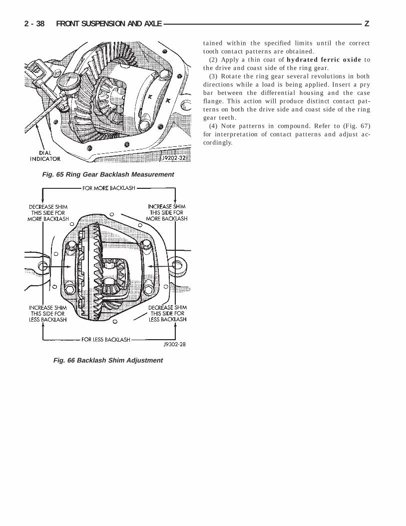
BACKLASH AND CONTACT PATTERN ANALYSIS(1) Rotate assembly several revolutions to seat
bearings. Measure backlash at three equally spacedlocations around the perimeter of the ring gear with adial indicator (Fig. 65).
The ring gear backlash must be within 0.005 -0.008 inch (0.12 - 0.20 mm). It cannot vary morethan 0.002 inch (0.05 mm) between the pointschecked.
If backlash must be adjusted, transfer shims fromone side of carrier to the other side. Adjust the back-lash accordingly (Fig. 66). DO NOT INCREASETHE TOTAL SHIM PACK THICKNESS, EXCES-SIVE BEARING PRELOAD AND DAMAGE MAYOCCUR.
If the mesh and backlash steps have been followedin the procedures above, good gear teeth contact pat-terns should exist.
The ring gear teeth contact patterns will show if thepinion gear depth shim(s) have the correct thickness.It will also show if the ring gear backlash has beenadjusted correctly. The backlash must be main-
Fig. 61 Differential Bearing Installation
Fig. 62 Spread Differential Housing
Fig. 63 Differential Installation
Fig. 64 Differential Bearing Cap Reference Letters
Z FRONT SUSPENSION AND AXLE 2 - 37
tained within the specified limits until the correcttooth contact patterns are obtained.
(2) Apply a thin coat of hydrated ferric oxide tothe drive and coast side of the ring gear.
(3) Rotate the ring gear several revolutions in bothdirections while a load is being applied. Insert a prybar between the differential housing and the caseflange. This action will produce distinct contact pat-terns on both the drive side and coast side of the ringgear teeth.
(4) Note patterns in compound. Refer to (Fig. 67)for interpretation of contact patterns and adjust ac-cordingly.
Fig. 65 Ring Gear Backlash Measurement
Fig. 66 Backlash Shim Adjustment
2 - 38 FRONT SUSPENSION AND AXLE Z
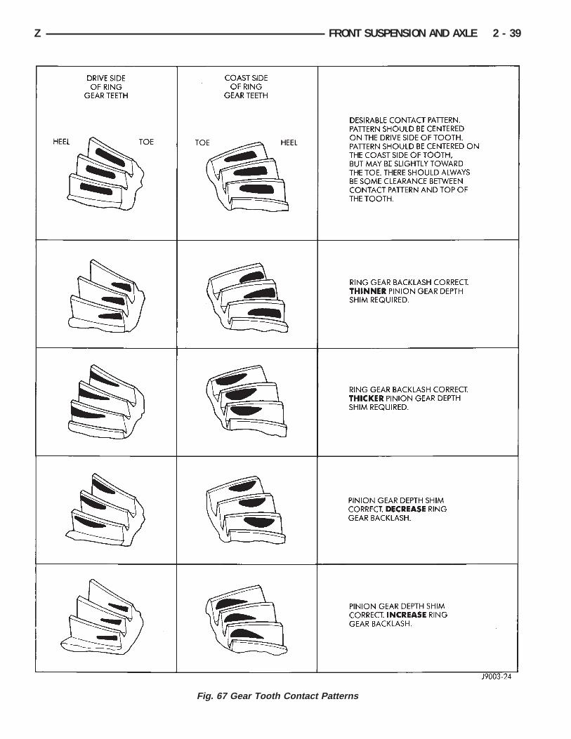
Fig. 67 Gear Tooth Contact Patterns
Z FRONT SUSPENSION AND AXLE 2 - 39

FINAL ASSEMBLY(1) Install the axle shafts. Refer to Axle Shaft In-
stallation in this Group.(2) Scrape the residual sealant from the housing
and cover mating surfaces. Clean the mating surfaceswith mineral spirits. Apply a bead of MOPARt Sili-cone Rubber Sealant on the housing cover (Fig. 68).Allow the sealant to cure for a few minutes.
Install the housing cover within 5 minutes af-ter applying the sealant. If not installed thesealant must be removed and another bead ap-plied.
(3) Install the cover on the differential with theattaching bolts. Install the identification tag. Tightenthe cover bolts with 47 NIm (35 ft. lbs.) torque.
CAUTION: Overfilling the differential can result inthe lubricant foaming and overheating.
(4) Refill the differential housing with the specifiedquantity of MOPARt Hypoid Gear Lubricant.
(5) Install the fill hole plug and tighten to 34 NIm(25 ft. lbs.) torque.
AXLE SPECIFICATIONSFig. 68 Typical Housing Cover With Sealant
MODEL 30 FRONT AXLE
2 - 40 FRONT SUSPENSION AND AXLE Z
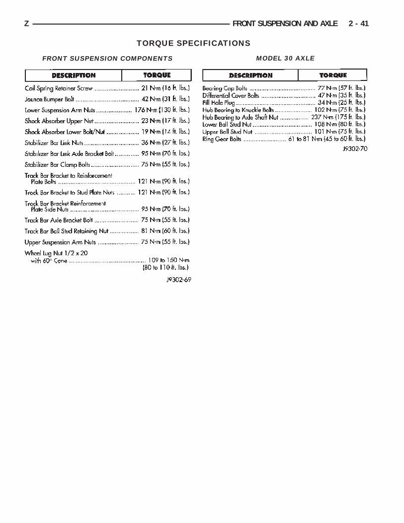
TORQUE SPECIFICATIONS
FRONT SUSPENSION COMPONENTS MODEL 30 AXLE
Z FRONT SUSPENSION AND AXLE 2 - 41

Recommended