FAX-1
FRONT AXLE
D DRIVELINE/AXLE
CONTENTS
C
E
F
G
H
I
J
K
L
M
SECTION FAXA
B
FAX
Revision: 2006 December 2006 FX35/FX45
FRONT AXLE
2WD
PREPARATION ........................................................... 2Special Service Tools (SST) ..................................... 2Commercial Service Tools ........................................ 2
NOISE, VIBRATION AND HARSHNESS (NVH) TROUBLESHOOTING ................................................ 3
NVH Troubleshooting Chart ..................................... 3FRONT WHEEL HUB AND KNUCKLE ...................... 4
On-Vehicle Inspection .............................................. 4WHEEL BEARING INSPECTION ......................... 4
Removal and Installation .......................................... 4COMPONENTS .................................................... 4REMOVAL ............................................................. 4INSPECTION AFTER REMOVAL ......................... 5INSTALLATION ..................................................... 5
SERVICE DATA AND SPECIFICATIONS (SDS) ........ 6Wheel Bearing .......................................................... 6
AWD
PRECAUTIONS .......................................................... 7Caution ..................................................................... 7
PREPARATION ........................................................... 8Special Service Tools (SST) ..................................... 8Commercial Service Tools ........................................ 8
NOISE, VIBRATION AND HARSHNESS (NVH) TROUBLESHOOTING ................................................ 9
NVH Troubleshooting Chart ..................................... 9FRONT WHEEL HUB AND KNUCKLE .................... 10
On-Vehicle Inspection ............................................ 10
WHEEL BEARING INSPECTION ....................... 10Removal and Installation ........................................ 10
COMPONENTS ................................................... 10REMOVAL ........................................................... 10INSPECTION AFTER REMOVAL ....................... 11INSTALLATION ................................................... 11
FRONT DRIVE SHAFT ............................................. 12Removal and Installation (Left Side) ....................... 12
COMPONENTS ................................................... 12REMOVAL ........................................................... 12INSPECTION AFTER REMOVAL ....................... 12INSTALLATION ................................................... 12
Removal and Installation (Right Side) .................... 13COMPONENTS ................................................... 13REMOVAL ........................................................... 13INSPECTION AFTER REMOVAL ....................... 13INSTALLATION ................................................... 14
Disassembly and Assembly (Left Side) .................. 14COMPONENTS ................................................... 14DISASSEMBLY ................................................... 15INSPECTION AFTER DISASSEMBLY ................ 15ASSEMBLY ......................................................... 16
Disassembly and Assembly (Right Side) ................ 19COMPONENTS ................................................... 19DISASSEMBLY ................................................... 20INSPECTION AFTER DISASSEMBLY ................ 20ASSEMBLY ......................................................... 21
SERVICE DATA AND SPECIFICATIONS (SDS) ...... 25Wheel Bearing ........................................................ 25Drive Shaft .............................................................. 25

FAX-2
[2WD]PREPARATION
Revision: 2006 December 2006 FX35/FX45
[2WD]PREPARATION PFP:00002
Special Service Tools (SST) NDS000BU
The actual shapes of Kent-Moore tools may differ from those of special service tools illustrated here.
Commercial Service Tools NDS000BV
Tool number(Kent-Moore No.)Tool name
Description
HT72520000(J−25730-A)Ball joint remover a: 33 mm (1.30 in) b: 50 mm (1.97 in) r: 11.5 mm (0.453 in)
● Removing steering outer socket
● Removing transverse link
NT546
Tool name Description
Power tool
● Removing wheel nuts
● Removing brake caliper assembly
● Removing strut lower side
● Removing wheel hub and bearing assembly
PBIC0190E

NOISE, VIBRATION AND HARSHNESS (NVH) TROUBLESHOOTING
FAX-3
[2WD]
C
E
F
G
H
I
J
K
L
M
A
B
FAX
Revision: 2006 December 2006 FX35/FX45
NOISE, VIBRATION AND HARSHNESS (NVH) TROUBLESHOOTING PFP:00003
NVH Troubleshooting Chart NDS000BW
Use chart below to help you find the cause of the symptom. If necessary, repair or replace these parts.
×: Applicable
Reference page
FAX
-4
—
FAX
-4
NV
H in
WT
sec
tion
NV
H in
WT
sec
tion
NV
H in
PS
sec
tion
Possible cause and SUSPECTED PARTS
Impr
oper
inst
alla
tion,
loos
enes
s
Par
ts in
terf
eren
ce
Whe
el b
earin
g da
mag
e
TIR
ES
RO
AD
WH
EE
L
ST
EE
RIN
G
Symptom FRONT AXLE
Noise × × × × ×
Shake × × × × ×
Vibration × × × ×
Shimmy × × × × ×
Judder × × × ×
Poor quality ride or handling × × × × ×

FAX-4
[2WD]FRONT WHEEL HUB AND KNUCKLE
Revision: 2006 December 2006 FX35/FX45
FRONT WHEEL HUB AND KNUCKLE PFP:40202
On-Vehicle Inspection NDS000BX
Make sure the mounting conditions (looseness, back lash) of each component and component status (wear,damage) are normal.
WHEEL BEARING INSPECTION● Move wheel hub in the axial direction by hand. Check that there is no looseness of front wheel bearing.
● Rotate wheel hub and make sure there is no unusual noise or other irregular conditions. If there are anyirregular conditions, replace wheel hub and bearing assembly.
Removal and Installation NDS000BY
COMPONENTS
REMOVAL1. Remove tires from vehicle with power tool.2. Remove brake caliper with power tool. Hang it in a place where it will not interfere with work. Refer to BR-
19, "FRONT DISC BRAKE" .NOTE:Avoid depressing brake pedal while brake caliper is removed.
3. Put alignment marks on disc rotor and wheel hub and bearingassembly, then remove disc rotor.
4. Remove wheel sensor from wheel hub and bearing assembly.Refer to BRC-55, "WHEEL SENSORS" .CAUTION:Do not pull on wheel sensor harness.
5. Remove cotter pin at steering outer socket, then loosen mount-ing nut.
Axial end play : 0.05 mm (0.002 in) or less
1. Disc rotor 2. Wheel hub and bearing assembly 3. Splash guard
4. Steering knuckle 5. Cotter pin
Refer to GI-11, "Components" , for the symbols in the figure.
PDIA1216E
SDIA1480E

FRONT WHEEL HUB AND KNUCKLE
FAX-5
[2WD]
C
E
F
G
H
I
J
K
L
M
A
B
FAX
Revision: 2006 December 2006 FX35/FX45
6. Use a ball joint remover (SST) to remove steering outer socketfrom steering knuckle. Be careful not to damage ball joint boot.CAUTION:Tighten temporarily mounting nut to prevent damage tothreads and to prevent ball joint remover (SST) from com-ing off.
7. Remove cotter pin at transverse link, then loosen mounting nut.
8. Use a ball joint remover (SST) to remove transverse link fromsteering knuckle. Be careful not to damage ball joint boot.CAUTION:Tighten temporarily mounting nut to prevent damage tothreads and to prevent ball joint remover (SST) from com-ing off.
9. Remove fixing bolts and nuts between strut assembly and steer-ing knuckle with power tool.
10. Remove steering knuckle from vehicle.11. Remove fixing bolts between steering knuckle and wheel hub
and bearing assembly with power tool.12. Remove splash guard and wheel hub and bearing assembly from steering knuckle.
INSPECTION AFTER REMOVALCheck for deformity, cracks and damage on each parts, replace if necessary.
Ball Joint Inspection ● Check for boot breakage, axial looseness, and torque of transverse link and steering outer socket ball
joint. Refer to FSU-14, "TRANSVERSE LINK" , PS-17, "POWER STEERING GEAR AND LINKAGE" .
INSTALLATION● Refer to FAX-4, "Removal and Installation" for tightening torque. Install in the reverse order of removal.
NOTE:Refer to component parts location and do not reuse non-reusable parts.
● After removing/installing or replacing axle components, check wheel alignment. Refer to FSU-6, "WheelAlignment Inspection" .
● After adjusting wheel alignment, adjust neutral position of steering angle sensor. Refer to BRC-6, "Adjust-ment of Steering Angle Sensor Neutral Position" .
● Check the following item after service– Installation condition of wheel sensor harness
SDIA1434E
SDIA1435E

FAX-6
[2WD]SERVICE DATA AND SPECIFICATIONS (SDS)
Revision: 2006 December 2006 FX35/FX45
SERVICE DATA AND SPECIFICATIONS (SDS) PFP:00030
Wheel Bearing NDS000BZ
Axial end play 0.05 mm (0.002 in) or less

PRECAUTIONS
FAX-7
[AWD]
C
E
F
G
H
I
J
K
L
M
A
B
FAX
Revision: 2006 December 2006 FX35/FX45
[AWD]PRECAUTIONS PFP:00001
Caution NDS000C0
Observe the following precautions when disassembling and servicing drive shaft.● Joint sub-assembly does not disassemble because it is non-overhaul parts.● Perform work in a location which is as dust-free as possible.● Before disassembling and servicing, clean the outside of parts.● Prevention of the entry of foreign objects must be taken into account during disassembly of the service
location.● Disassembled parts must be carefully reassembled in the correct order. If work is interrupted, a clean
cover must be placed over parts.● Paper shop cloths must be used. Fabric shop cloths must not be used because of the danger of lint adher-
ing to parts.● Disassembled parts (except for rubber parts) should be cleaned with kerosene which shall be removed by
blowing with air or wiping with paper shop cloths.

FAX-8
[AWD]PREPARATION
Revision: 2006 December 2006 FX35/FX45
PREPARATION PFP:00002
Special Service Tools (SST) NDS000C1
The actual shapes of Kent-Moore tools may differ from those of special service tools illustrated here.
Commercial Service Tools NDS000C2
Tool number (Kent-Moore No.)Tool name
Description
HT72520000 (J−25730-A)Ball joint remover a: 33 mm (1.30 in) b: 50 mm (1.97 in) r: 11.5 mm (0.453 in)
● Removing steering outer socket
● Removing transverse link
KV40107300( – )Boot band crimping tool
Installing boot band
KV38107900( – )Protectora: 32 mm (1.26 in) dia.
Installing drive shaft
KV38100500( – )Drifta: 80 mm (3.15 in) dia.b: 60 mm (2.36 in) dia.
Installing drive shaft plug
KV38102200( – )Drifta: 90 mm (3.54 in) dia.b: 31 mm (1.22 in) dia.
Installing drive shaft plug
NT546
ZZA1229D
ZZA0835D
ZZA0701D
ZZA0920D
Tool name Description
Power tool
● Removing wheel nuts
● Removing brake caliper assembly
● Removing hub lock nut
● Removing strut lower side
● Removing wheel hub and bearing assembly
● Removing undercoverPBIC0190E

NOISE, VIBRATION AND HARSHNESS (NVH) TROUBLESHOOTING
FAX-9
[AWD]
C
E
F
G
H
I
J
K
L
M
A
B
FAX
Revision: 2006 December 2006 FX35/FX45
NOISE, VIBRATION AND HARSHNESS (NVH) TROUBLESHOOTING PFP:00003
NVH Troubleshooting Chart NDS000C3
Use chart below to help you find the cause of the symptom. If necessary, repair or replace these parts.
×: Applicable
Reference page —
FAX
-15
—
FAX
-10
—
FAX
-10
NV
H in
FF
D s
ectio
n
NV
H in
FA
X a
nd F
SU
sec
tion
Ref
er to
FR
ON
T A
XLE
in th
is c
hart
.
NV
H in
WT
sec
tion
NV
H in
WT
sec
tion
Ref
er to
DR
IVE
SH
AF
T in
this
cha
rt.
NV
H in
BR
sec
tion
NV
H in
PS
sec
tion
Possible cause and SUSPECTED PARTS
Exc
essi
ve jo
int a
ngle
Join
t slid
ing
resi
stan
ce
Imba
lanc
e
Impr
oper
inst
alla
tion,
loos
enes
s
Par
ts in
terf
eren
ce
Whe
el b
earin
g da
mag
e
FR
ON
T D
IFF
ER
EN
TIA
L
FR
ON
T A
XLE
AN
D F
RO
NT
SU
SP
EN
SIO
N
FR
ON
T A
XLE
TIR
ES
RO
AD
WH
EE
L
DR
IVE
SH
AF
T
BR
AK
ES
ST
EE
RIN
G
Symptom
DRIVE SHAFT
Noise × × × × × × × × × ×
Shake × × × × × × × × ×
FRONT AXLE
Noise × × × × × × × × × ×
Shake × × × × × × × × ×
Vibration × × × × × × ×
Shimmy × × × × × × ×
Judder × × × × × ×
Poor quality ride or handling × × × × ×

FAX-10
[AWD]FRONT WHEEL HUB AND KNUCKLE
Revision: 2006 December 2006 FX35/FX45
FRONT WHEEL HUB AND KNUCKLE PFP:40202
On-Vehicle Inspection NDS000D0
Make sure the mounting conditions (looseness, back lash) of each component and component status (wear,damage) are normal.
WHEEL BEARING INSPECTION● Move wheel hub in the axial direction by hand. Check that there is no looseness of front wheel bearing.
● Rotate wheel hub and make sure there is no unusual noise or other irregular conditions. If there are anyirregular conditions, replace wheel hub and bearing assembly.
Removal and Installation NDS000C5
COMPONENTS
REMOVAL1. Remove tires from vehicle with power tool.2. Remove brake caliper with power tool. Hang it in a place where it will not interfere with work. Refer to BR-
20, "Removal and Installation of Brake Caliper Assembly" .NOTE:Avoid depressing brake pedal while brake caliper is removed.
3. Put alignment marks on disc rotor and wheel hub and bearingassembly, then remove disc rotor.
4. Remove wheel sensor from steering knuckle. Refer to BRC-55,"WHEEL SENSORS"CAUTION:Do not pull on wheel sensor harness.
5. Remove cotter pin, then remove lock nut from drive shaft.6. Remove steering outer socket and cotter pin at steering knuckle, then loosen mounting nut.
Axial end play : 0.05 mm (0.002 in) or less
1. Cotter pin 2. Washer 3. Disc rotor
4. Wheel hub and bearing assembly 5. Splash guard 6. Steering knuckle
Refer to GI-11, "Components" , for the symbols in the figure.
PDIA1217E
SDIA1480E

FRONT WHEEL HUB AND KNUCKLE
FAX-11
[AWD]
C
E
F
G
H
I
J
K
L
M
A
B
FAX
Revision: 2006 December 2006 FX35/FX45
7. Use a ball joint remover (SST) to remove steering outer socketfrom steering knuckle. Be careful not to damage ball joint boot.CAUTION:To prevent damage to threads and to prevent ball jointremover (SST) from coming off suddenly, temporarilytighten mounting nut.
8. Using a puller (suitable tool), remove wheel hub and bearing assembly from drive shaft.NOTE:● When removing wheel hub and bearing assembly, do not apply an excessive angle to drive shaft joint.
Also be careful not to excessively extend slide joint.● Do not hang over drive shaft with out support.
9. Remove wheel hub and bearing assembly fixing bolt.10. Remove splash guard and wheel hub and bearing assembly from steering knuckle.11. Remove strut assembly and steering knuckle fixing bolts and nuts.12. Remove transverse link and steering knuckle fixing bolt and nut.13. Remove steering knuckle from vehicle.
INSPECTION AFTER REMOVALCheck for deformity, cracks and damage on each parts, replace if necessary.
Ball Joint InspectionCheck for boot breakage, axial looseness, and torque of transverse link and steering outer socket ball joint.Refer to FSU-14, "TRANSVERSE LINK" , PS-17, "POWER STEERING GEAR AND LINKAGE" .
INSTALLATIONCAUTION:Be sure to replace the new differential side oil seal every removal of drive shaft. Refer to FFD-11,"SIDE OIL SEAL" .● Refer to FAX-10, "Removal and Installation" for tightening torque. Install in the reverse order of removal.
NOTE:Refer to component parts location and do not reuse non-reusable parts.
● To assemble disc rotor and wheel hub and bearing assembly,align the marks.(When not using the alignment mark, refer to BR-20, "Removaland Installation of Brake Caliper Assembly" .)
SGIA0488E
SDIA1480E

FAX-12
[AWD]FRONT DRIVE SHAFT
Revision: 2006 December 2006 FX35/FX45
FRONT DRIVE SHAFT PFP:39100
Removal and Installation (Left Side) NDS000C6
COMPONENTS
REMOVAL1. Remove tires from vehicle with power tool.2. Remove undercover with power tool.3. Remove cotter pin. Then remove lock nut from drive shaft with power tool.4. Remove wheel sensor harness from strut assembly. Refer to BRC-55, "WHEEL SENSORS" .
CAUTION:Do not pull on wheel sensor harness.
5. Remove brake hose lock plate. Then remove brake hose from strut assembly. Refer to BR-11, "BRAKETUBE AND HOSE" .
6. Remove fixing bolts and nuts between strut assembly and steering knuckle with power tool. 7. Using a puller (suitable tool), remove drive shaft from steering
knuckle.CAUTION:When removing drive shaft, do not apply an excessiveangle to drive shaft joint. Also be careful not to excessivelyextend slide joint.
8. Remove fixing bolt of front final drive side assembly drive shaftwith power tool, then remove drive shaft from vehicle.
INSPECTION AFTER REMOVAL● Move joint up/down, left /right, and in the axial direction. Check for any rough movement or significant
looseness.● Check boot for cracks or other damage, and also for grease
leakage.● If a trouble is found, disassemble drive shaft, and then replace
with new one.
INSTALLATION● Refer to FAX-12, "Removal and Installation (Left Side)" for tightening torque. Install in the reverse order of
removal.
1. Cotter pin 2. Washer 3. Drive shaft
Refer to GI-11, "Components" , for the symbols in the figure.
PDIA1218E
SDIA0972J
SDIA1046J

FRONT DRIVE SHAFT
FAX-13
[AWD]
C
E
F
G
H
I
J
K
L
M
A
B
FAX
Revision: 2006 December 2006 FX35/FX45
NOTE:Refer to component parts location and do not reuse non-reusable parts.
● Check the following item after service.– Installation condition of wheel sensor harness
Removal and Installation (Right Side) NDS000C7
COMPONENTS
REMOVAL1. Remove tires from vehicle with power tool.2. Remove undercover with power tool.3. Remove cotter pin. Then remove lock nut from drive shaft with power tool.4. Remove wheel sensor harness from strut assembly. Refer to BRC-55, "WHEEL SENSORS" .
CAUTION:Do not pull on wheel sensor harness.
5. Remove brake hose lock prate. Then remove brake hose from strut assembly. Refer to BR-11, "BRAKETUBE AND HOSE" .
6. Remove fixing bolts and nuts between strut assembly and steering knuckle with power tool.7. Using a puller (suitable tool), remove drive shaft from steering
knuckle.CAUTION:When removing drive shaft, do not apply an excessiveangle to drive shaft joint. Also be careful not to excessivelyextend slide joint.
8. Pry off drive shaft from front final drive assembly side as shownin the figure.
INSPECTION AFTER REMOVAL● Move joint up/down, left/right, and in the axial direction. Check for any rough movement or significant
looseness.
1. Cotter pin 2. Washer 3. Drive shaft
Refer to GI-11, "Components" , for the symbols in the figure.
PDIA1219E
SDIA0972J
SDIA1489E
FAX-14
[AWD]FRONT DRIVE SHAFT
Revision: 2006 December 2006 FX35/FX45
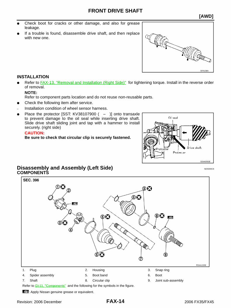
● Check boot for cracks or other damage, and also for greaseleakage.
● If a trouble is found, disassemble drive shaft, and then replacewith new one.
INSTALLATION● Refer to FAX-13, "Removal and Installation (Right Side)" for tightening torque. Install in the reverse order
of removal.NOTE:Refer to component parts location and do not reuse non-reusable parts.
● Check the following item after service.– Installation condition of wheel sensor harness.● Place the protector [SST: KV38107900 ( – )] onto transaxle
to prevent damage to the oil seal while inserting drive shaft.Slide drive shaft sliding joint and tap with a hammer to installsecurely. (right side)CAUTION:Be sure to check that circular clip is securely fastened.
Disassembly and Assembly (Left Side) NDS000C8
COMPONENTS
SFA108A
SDIA0593E
1. Plug 2. Housing 3. Snap ring
4. Spider assembly 5. Boot band 6. Boot
7. Shaft 8. Circular clip 9. Joint sub-assembly
Refer to GI-11, "Components" and the following for the symbols in the figure.
: Apply Nissan genuine grease or equivalent.
PDIA1220E

FRONT DRIVE SHAFT
FAX-15
[AWD]
C
E
F
G
H
I
J
K
L
M
A
B
FAX
Revision: 2006 December 2006 FX35/FX45
DISASSEMBLYFront Final Drive Assembly Side1. Press drive shaft in a vice.
CAUTION:When retaining shaft in a vice, always use copper or aluminum plates between vise and shaft.
2. Remove boot bands.3. If plug needs to be removed, move boot to wheel side, and drive it out with a plastic hammer.4. Put matching marks on spider assembly and shaft.
CAUTION:Use paint for matching mark, but don’t damage to spiderassembly and drive shaft.
5. Remove snap ring, then remove spider assembly from shaft.6. Remove boot from shaft.7. Remove old grease on slide joint assembly with paper towels.
Wheel Side1. Place drive shaft in a vice.
CAUTION:When retaining drive shaft in a vice, always use copper or aluminum plates between a vise andshaft.
2. Remove boot bands. Then remove boot from joint sub-assembly.3. Screw a drive shaft puller (suitable tool) 30 mm (1.18 in) or more
into threaded part of joint sub-assembly. Pull joint sub-assemblyout of shaft.CAUTION:● If joint sub-assembly cannot be removed after five or
more unsuccessful attempts, replace shaft and joint sub-assembly as a set.
● Align sliding hammer and drive shaft and remove themby pulling directly.
4. Remove boot from shaft.5. Remove circular clip from shaft.6. While rotating ball cage, remove old grease on joint sub-assembly with paper towels.
INSPECTION AFTER DISASSEMBLYShaftReplace shaft if there is any runout, cracking, or other damage.
Joint Sub-Assembly● Make sure there is no rough rotation or unusual axial looseness.● Make sure there is no foreign material inside joint sub-assembly.
SFA963
SFA612
SDIA0606E

FAX-16
[AWD]FRONT DRIVE SHAFT
Revision: 2006 December 2006 FX35/FX45
● Check joint sub-assembly for compression scar, cracks or fractures.CAUTION:If there are any irregular conditions of joint sub-assembly components, replace the entire jointsub-assembly.
Slide Joint SideHousing and spider assembly● If roller or roller surface of spider assembly has scratch or wear, replace housing and spider assembly.
NOTE:Housing and spider assembly are components which are used as a set.
ASSEMBLYFront Final Drive Assembly Side1. If plug has been removed, use a drift (SST) to press in a new
one.NOTE:Discard old plug; replace with new ones.
2. Wind serrated part of shaft with tape. Install boot band and bootto shaft. Be careful not to damage boot.NOTE:Discard old boot band and boot; replace with each new one.
3. Remove protective tape wound around serrated part of shaft.
4. Line up alignment marks which were made when spider assem-bly was removed. Install spider assembly, with serration chamferfacing shaft.
SDIA1153E
SFA800
SDIA1792E

FRONT DRIVE SHAFT
FAX-17
[AWD]
C
E
F
G
H
I
J
K
L
M
A
B
FAX
Revision: 2006 December 2006 FX35/FX45
5. Secure spider assembly with snap ring.NOTE:Discard old snap ring; replace with new one.
6. Apply Nissan genuine grease or equivalent to spider assemblyand sliding surface.
7. Install housing to spider assembly. Apply Nissan genuine greaseor equivalent to housing.
8. Install boot securely into grooves (indicated by * marks) shownin the figure.CAUTION:If there is grease on boot mounting surfaces (indicated by *marks) of shaft and housing, boot may come off. Removeall grease from surfaces.
9. Make sure boot installation length “L” is the length indicatedbelow. Insert a flat-bladed screwdriver or similar tool into smallerside of boot. Bleed air from boot to prevent boot deformation.
CAUTION:● Boot may break if boot installation length is less than standard value.● Take care not to touch the tip of screwdriver to inside surface of boot.
10. Install new larger and smaller boot bands securely.NOTE:Discard old boot bands; replace with new ones.
11. After installing housing and shaft, rotate boot to check whetheror not the actual position is correct. If boot position is not correct,secure boot with new boot bands again.
12. Install circular clip.NOTE:Discard old circular clip; replace with new one.
SFA023A
Grease amount : 77 − 97 g (2.72 − 3.42 oz)
SDIA1445E
Boot installation Length “L ”: 150.9 − 152.9 mm (5.94 − 6.02 in)
SDIA3249E
SFA395

FAX-18
[AWD]FRONT DRIVE SHAFT
Revision: 2006 December 2006 FX35/FX45
Wheel Side1. Insert the amount grease (Nissan genuine grease or equivalent)
into joint sub-assembly serration hole until grease begins toooze from ball groove and serration hole. After inserting grease,use a shop cloth to wipe off old grease that has oozed out.
2. Wind serrated part of shaft with tape. Install boot band and bootto shaft. Be careful not to damage boot.NOTE:Discard old boot band and boot; replace with new ones.
3. Remove protective tape wound around serrated part of shaft.
4. Attach circular clip to shaft. At this time, circular clip must fitsecurely into shaft groove. Attach nut to joint sub-assembly.Use a wooden hammer to press-fit.NOTE:Discard old circular clip; replace with new one.
5. Insert the specified amount of grease (Nissan genuine grease orequivalent) listed below into boot from large end of boot.
6. Install boot securely into grooves (indicated by * marks) shownin the figure.CAUTION:If there is grease on boot mounting surfaces (indicated by*marks) of shaft and housing of joint sub assembly, bootmay come off. Remove all grease from surfaces.
7. Make sure boot installation length “L” is the length indicatedbelow. Insert a flat-bladed screwdriver or similar tool into smallerside of boot. Bleed air from boot to prevent boot deformation.
CAUTION:● Boot may brake if boot installation length is less than standard value.● Be careful that screwdriver tip does not contact inside surface of boot.
SDIA1127E
SFA800
Grease amount : 95 − 115 g (3.35 − 4.06 oz)
RAC0049D
Boot installation length “L” : 136 mm (5.35 in)SDIA3250E

FRONT DRIVE SHAFT
FAX-19
[AWD]
C
E
F
G
H
I
J
K
L
M
A
B
FAX
Revision: 2006 December 2006 FX35/FX45
8. Secure the large and small ends of the boot with new boot bandusing the boot band crimping tool [SST: KV40107300] as shownin the figure. NOTE:● Discard old boot bands; replace with new ones.
● Secure boot band so that dimension “M” shown bellow rightsatisfies the following:
9. After installing joint sub-assembly and shaft, rotate boot to checkwhether or not the actual position is correct. If boot position isnot correct, secure boot with new boot bands again.
Disassembly and Assembly (Right Side) NDS000C9
COMPONENTS
RAC1133D
Large diameter side : 3.0 mm (0.118 in)Small diameter side : 2.0 mm (0.079 in)
DSF0047D
1. Joint sub-assembly 2. Circular clip 3. Boot band
4. Boot 5. Shaft 6. Spider assembly
7. Snap ring 8. Housing 9. Dust shield
10. Circular clip
Refer to GI-11, "Components" and the following for the symbols in the figure.
: Apply Nissan genuine grease or equivalent.
PDIA1221E

FAX-20
[AWD]FRONT DRIVE SHAFT
Revision: 2006 December 2006 FX35/FX45
DISASSEMBLYFront Final Drive Assembly Side1. Press drive shaft in a vice.
CAUTION:When retaining drive shaft in a vice, always use copper or aluminum plates between a vise andshaft.
2. Remove boot bands.3. Put matching marks on spider assembly and shaft.
CAUTION:Use paint for matching mark, but don’t damage to spiderassembly and shaft.
4. Remove snap ring, then remove spider assembly from shaft.5. Remove boot from shaft.6. Remove old grease on slide joint assembly with paper towels.
Wheel Side1. Place drive shaft in a vice.
CAUTION:When retaining drive shaft in a vice, always use copper or aluminum plates between vise a andshaft.
2. Remove boot bands. Then remove boot from joint sub-assembly.3. Screw a drive shaft puller (suitable tool) 30 mm (1.18 in) or more
into threaded part of joint sub-assembly. Pull joint sub-assemblyout of shaft.CAUTION:● If joint sub-assembly cannot be removed after five or
more unsuccessful attempts, replace shaft and joint sub-assembly as a set.
● Align sliding hammer and drive shaft and remove themby pulling directly.
4. Remove boot from shaft.5. Remove circular clip from shaft.6. While rotating ball cage, remove old grease on joint sub-assembly with paper towels.
INSPECTION AFTER DISASSEMBLYShaftReplace shaft if there is any runout, cracking, or other damage.
Joint Sub-Assembly● Make sure there is no rough rotation or unusual axial looseness.● Make sure there is no foreign material inside joint sub-assembly.
SFA963
SFA612
SDIA0606E

FRONT DRIVE SHAFT
FAX-21
[AWD]
C
E
F
G
H
I
J
K
L
M
A
B
FAX
Revision: 2006 December 2006 FX35/FX45
● Check joint sub-assembly for compression scar, cracks or fractures.● If there are any irregular conditions of joint sub-assembly components, replace the entire joint sub-assem-
bly.
Slide Joint SideHousing and spider assembly● If roller or roller surface of spider assembly has scratch or wear, replace housing and spider assembly.
NOTE:Housing and spider assembly are components which are used as a set.
ASSEMBLYFront Final Drive Assembly Side1. Wind serrated part of drive shaft with tape. Install boot band and
boot to shaft. Be careful not to damage boot.NOTE:Discard old boot band and boot; replace with each new one.
2. Remove protective tape wound around serrated part of shaft.
3. Line up alignment marks which were made when spider assem-bly was removed. Install spider assembly, with serration chamferfacing dive shaft.
4. Secure spider assembly with snap ring.NOTE:Discard old snap ring; replace with new one.
5. Apply Nissan genuine grease or equivalent to spider assemblyand sliding surface.
6. Install housing to spider assembly. Apply Nissan genuine greaseor equivalent to housing.
SFA800
SDIA1735E
SFA023A
Grease amount : 113 − 123 g (3.99 − 4.34 oz)
SDIA1446E

FAX-22
[AWD]FRONT DRIVE SHAFT
Revision: 2006 December 2006 FX35/FX45
7. Install boot securely into grooves (indicated by * marks) shownin the figure.CAUTION:If there is grease on boot mounting surfaces (indicated by*marks) of shaft and housing, boot may come off. Removeall grease from surfaces.
8. Make sure boot installation length “L” is the length indicatedbelow. Insert a flat-bladed screwdriver or similar tool into smallerside of boot. Bleed air from boot to prevent boot deformation.
CAUTION:● Boot may break if boot installation length is less than standard value.● Take care not to touch the tip of screwdriver to inside surface of boot.
9. Install new larger and smaller boot bands securely.NOTE:Discard old boot bands; replace with new ones.
10. Set boot band in the specified grooves. Fit band's pawl to thegrooves and tack them.
11. Pull and tighten the pawls of tool hanger by using a pair of long-nose pliers.
12. Insert band's tip into end of tool pawl.13. After installing housing and shaft, rotate boot to check whether
or not the actual position is correct. If boot position is not correct,secure boot with new boot bands again.
14. Install circular clip.NOTE:Discard old circular clip; replace with new one.
Boot installation Length “L ”:157.8 − 159.8 mm (6.21 − 6.29 in)
SDIA3250E
SDIA3053J
SDIA3054J
SDIA3055J

FRONT DRIVE SHAFT
FAX-23
[AWD]
C
E
F
G
H
I
J
K
L
M
A
B
FAX
Revision: 2006 December 2006 FX35/FX45
Wheel Side1. Insert the amount grease (Nissan genuine grease or equivalent)
into joint sub-assembly serration hole until grease begins toooze from ball groove and serration hole. After inserting grease,use a shop cloth to wipe off old grease that has oozed out.
2. Wind serrated part of shaft with tape. Install boot band and bootto shaft. Be careful not to damage boot.NOTE:Discard old boot band and boot; replace with new ones.
3. Remove protective tape wound around serrated part of shaft.
4. Attach circular clip to shaft. At this time, circular clip must fitsecurely into shaft groove. Attach nut to joint sub-assembly.Use a wooden hammer to press-fit.NOTE:Discard old circular clip; replace with new one.
5. Insert the specified amount of grease (Nissan genuine grease orequivalent) listed below into boot from large end of boot.
6. Install boot securely into grooves (indicated by * marks) shownin the figure.CAUTION:If there is grease on boot mounting surfaces (indicated by*marks) of shaft and housing of joint sub-assembly, bootmay come off. Remove all grease from surfaces.
7. Make sure boot installation length “L” is the length indicatedbelow. Insert a flat-bladed screwdriver or similar tool into smallerside of boot. Bleed air from boot to prevent boot deformation.
CAUTION:● Boot may brake if boot installation length is less than standard value.● Be careful that screwdriver tip does not contact inside surface of boot.
SDIA1127E
SFA800
Grease amount : 95 − 115 g (3.35 − 4.06 oz)
RAC0049D
Boot installation length “L” : 136 mm (5.35 in) SDIA3250E

FAX-24
[AWD]FRONT DRIVE SHAFT
Revision: 2006 December 2006 FX35/FX45
8. Secure the large and small ends of the boot with new boot bandusing the boot band crimping tool [SST: KV40107300] as shownin the figure. NOTE:● Discard old boot band; replace with new ones.
● Secure boot band so that dimension “M” shown bellow rightsatisfies the following:
9. After installing joint sub-assembly and shaft, rotate boot to checkwhether or not the actual position is correct. If boot position isnot correct, secure boot with new boot bands again.
RAC1133D
Large diameter side : 3.0 mm (0.118 in)Small diameter side : 2.0 mm (0.079 in)
DSF0047D

SERVICE DATA AND SPECIFICATIONS (SDS)
FAX-25
[AWD]
C
E
F
G
H
I
J
K
L
M
A
B
FAX
Revision: 2006 December 2006 FX35/FX45
SERVICE DATA AND SPECIFICATIONS (SDS) PFP:00030
Wheel Bearing NDS000CA
Drive Shaft NDS000CB
Axial end play 0.05 mm (0.002 in) or less
Joint type (Wheel side) (Transaxle side)
Grease quantity 77 − 97 g (2.72 − 3.42 oz)95 − 105 g (3.35 − 3.70 oz) (LH side)
113 − 123 g (3.99 − 4.34 oz) (RH side)
Boots installed length 136 mm (5.35 in)150.9 − 152.9 mm (5.94 − 6.02 in) (LH side)157.8 − 159.8 mm (6.21 − 6.29 in) (RH side)

FAX-26
[AWD]SERVICE DATA AND SPECIFICATIONS (SDS)
Revision: 2006 December 2006 FX35/FX45
Recommended