European ProjectFire Resistance of Innovative and Slender Concrete Filled
Tubular Composite Columns (FRISCC)
Prof Leroy Gardner
Dr Finian McCann
Elliptical section members

OUTLINE
FRISCC - Fire Resistance of Innovative and Slender Concrete Filled Tubular Composite Columns
1. STEEL EHS MEMBERS
INTRODUCTION
STRUCTURAL INVESTIGATIONS
DESIGN RULES
2. CONCRETE-FILLED EHS MEMBERS
INTRODUCTION
TESTING AND SIMULATIONS
DESIGN GUIDANCE
DESIGN EXAMPLE
Elliptical section members

FRISCC
Steel EHS members:
• Recently introduced as hot-finished products in
EN 10210
• Combine merits of CHS and RHS
• Elegant aesthetics (CHS)
• Differing rigidities about principal axes
(RHS)� more suitable for applications in
bending
STEEL EHS MEMBERS - INTRODUCTION
a
a
b b
z
y

FRISCC
Applications of steel EHS
STEEL EHS MEMBERS - APPLICATIONS
Heathrow Airport, UK Jarrold store, UK

FRISCC
Applications of steel EHS
STEEL EHS MEMBERS - APPLICATIONS
Madrid Airport, Spain Society Bridge, Scotland
FRISCC
Structural scenarios addressed:
1. Local buckling and cross-section classification
2. Shear resistance
3. Combined bending and shear
4. Flexural buckling of columns
STEEL EHS MEMBERS – STRUCTURAL INVESTIGATIONS

FRISCC
Cross-section classification:
STEEL EHS MEMBERS – CROSS-SECTION CLASSIFICATION
b
b
a a
z
y
In compression or minor
axis bending, equivalent
diameter is:
De
= 2rmax
=2a2/b
Elastic critical local buckling – compression and minor axis bending
Initial aim was to determine an equivalent CHS diameter De
rmax)(r
tE
max
cr2
13 ν−
=σ

FRISCC
Cross-section classification:
STEEL EHS MEMBERS – CROSS-SECTION CLASSIFICATION
rmax
is the maximum local
radius of curvature
a
a
b b
rmax
Maximum
compression
Compression
Tension
z
y
Buckling
initiates
De= 0.8a2/b
Elastic critical local buckling – major axis bending

FRISCC
Cross-section classification – Testing:
STEEL EHS MEMBERS – CROSS-SECTION CLASSIFICATION
Material testing of
tensile coupons
Geometric
measurementsCompression
tests
Minor axis bending tests

FRISCC
Cross-section classification – Finite element modelling:
STEEL EHS MEMBERS – CROSS-SECTION CLASSIFICATION
• FE models developed in ABAQUS
• Models validated against test results
• Full loading history and failure modes well predicted
• Parametric studies conducted, varying:
• Cross-section slenderness
• Aspect ratios (for all tests, a/b = 2)

FRISCC
Cross-section classification – FE validation:
STEEL EHS MEMBERS – CROSS-SECTION CLASSIFICATION
0
600
1200
1800
0 6 12 18 24
End shortening δ (mm)
Lo
ad
N(k
N)
FE
Test

FRISCC
Cross-section classification:
STEEL EHS MEMBERS – CROSS-SECTION CLASSIFICATION
De/tε2
Fu/F
y
0.0
0.5
1.0
1.5
2.0
0 30 60 90 120 150 180 210 240 270
2a
2b
EHS
CHS
FE
Class 1-3 Class 4
De = 2rmax = 2a2/b
ε = (235/fy)0.5
Max. load Fu
normalised by yield load Fy

FRISCC
Cross-section classification:
STEEL EHS MEMBERS – CROSS-SECTION CLASSIFICATION
Minor axis bending – ultimate moment to elastic moment
De/tε2
Mu/M
el
0.0
0.5
1.0
1.5
2.0
2.5
0 20 40 60 80 100 120 140 160 180 200 220 240 260
EHS
CHS
FE
2a
2b
Class 4Class 1-3
De = 2rmax = 2a2/b
ε = (235/fy)0.5

FRISCC
Cross-section classification – summary of measurements of slenderness:
STEEL EHS MEMBERS – CROSS-SECTION CLASSIFICATION
Loading Equivalent diameterCorresponding point on
cross-section
2a
2b
Axial
compressionDe = 2a
2/b
2a
2b
Minor axis
bending (z-z)De = 2a
2/b
2b
2aMajor axis
bending (y-y)
De = 0.8a2/b a/b > 1.36
2b
2a
De = 2b2/a a/b ≤ 1.36

FRISCC
Cross-section classification – summary of slenderness limits:
STEEL EHS MEMBERS – CROSS-SECTION CLASSIFICATION
Type of
compression
loading
Diameter
ratio
Proposed slenderness limits
Class 1 Class 2 Class 3
Axial
compression D
e/t Not applicable 90ε2
Minor axis
bending (z-y)D
e/t
50ε2 70ε2 140ε2
Major axis
bending (y-y)D
e/t

FRISCC
Shear resistance:
STEEL EHS MEMBERS – SHEAR RESISTANCE
• Three-point bending tests (a/b = 2):
• 12 major axis, 12 minor axis
• Varying slenderness and length
L/2 L/2
F
Moment gradient
Uniform shear
Uniform shear

FRISCC
STEEL EHS MEMBERS – SHEAR RESISTANCE
Design plastic shear resistance:
(Av = shear area, fy = yield strength, γM0 = 1.0)
0
,
3/
M
yv
Rdpl
fAV
γ=
b b
a
a
z
y
For shear along z-z:
a a
b
b
z
y
For shear along y-y:
Av = (4b-2t)t A
v = (4a-2t)t

FRISCC
STEEL EHS MEMBERS – SHEAR RESISTANCE
Moment–shear interaction design guidance based on test results:
0.0
0.5
1.0
1.5
0.00 0.25 0.50 0.75 1.00 1.25
Vu/Vpl,Rd
Mu/M
pl,Rd
or M
u/M
el,Rd
Shear along y-y
Shear along z-z
Proposed shear-moment
interaction

FRISCC
Column buckling:
STEEL EHS MEMBERS – COLUMN BUCKLING
• Column tests performed (a/b = 2):
• 12 major axis, 12 minor axis, varying slenderness and length
Knife edge
Load cell
LVDT
Strain gauge
CL
Hydraulic jack

FRISCC
Column buckling – finite element validation:
STEEL EHS MEMBERS – COLUMN BUCKLING
0
250
500
750
0 15 30 45 60
Lateral deflection at mid-height ω (mm)
Lo
ad
N (
kN
)
Test
FE

0.0
0.5
1.0
1.5
0.0 0.4 0.8 1.2 1.6 2.0 2.4 2.8
Member slenderness λ
Buckling about z-z
Buckling about y-yN
u/N
yo
r N
u/N
eff
z
y
EC3 – curve ‘a’
STEEL EHS MEMBERS – COLUMN BUCKLING
Buckling curve ‘a’ can be used for EHS, as for other hot-finished
hollow sections

STEEL EHS MEMBERS – COLUMN BUCKLING
Design guidance:
• Presented proposals are
reflected in the Blue book
• Also in equivalent US
design guidance
• Expected to be
incorporated in future
revisions of EC3

FRISCC
Steel EHS members - conclusions:
STEEL EHS MEMBERS – SUMMARY
• New addition to hot-rolled range
• Significant testing and FE modelling programmes
• Design rules for primary structural configurations
• Incorporation into structural design codes ongoing

FRISCC
Concrete-filled EHS columns:
• Design guidance currently exists for other concrete-filled tubular
columns (CHS, SHS, RHS)
• No current guidance for emerging CFEHS structural solution
• Among aims of FRISCC project: develop guidance on the design
of CFEHS columns
• At room temperature (Imperial College)
• In fire conditions (UP Valencia)
CONCRETE-FILLED EHS MEMBERS - INTRODUCTION

FRISCC
Current guidance:
• Cross-section classification - Eurocode 4: “composite section classified
according to least favourable class of steel elements in compression” (using
Eurocode 3 limits)
• Resistance of compression members: not available for CFEHS
� adopt rules for CHS / RHS?
Strategy for development of design guidance:
• Experimental programme
• Validation of numerical model against experiments
• Numerical parametric study
• Develop design rules for CFEHS columns and beam-columns based on results
CONCRETE-FILLED EHS MEMBERS - INTRODUCTION

FRISCC
Experimental investigation:
• 27 concrete-filled 150×75×6.3 EHS
specimens tested in compression
• Grade S355 steel, grade C30 concrete
• Loading was either concentric or with various
major / minor axis eccentricities
• Specimens with different global slenderness
(lengths) examined
• Some specimens with steel reinforcement
(4No. T10 bars)
CONCRETE-FILLED EHS MEMBERS - EXPERIMENTS

FRISCC
Cross-sectional geometry of experimental specimens:
CONCRETE-FILLED EHS MEMBERS - EXPERIMENTS
a
b
ez
ey
Position of eccentric load
10 mm
18 mm
Specimen buckling about major
axis
Specimen buckling about minor
axis
40 mm
15 mm
T10 reinforcing bar

FRISCC
Testing of columns:
CONCRETE-FILLED EHS MEMBERS - EXPERIMENTS
FRISCC
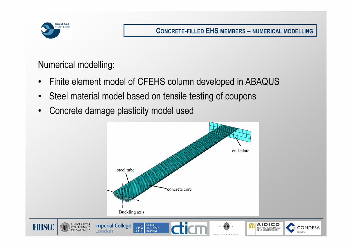
Numerical modelling:
• Finite element model of CFEHS column developed in ABAQUS
• Steel material model based on tensile testing of coupons
• Concrete damage plasticity model used
CONCRETE-FILLED EHS MEMBERS – NUMERICAL MODELLING
concrete core
steel tube
Buckling axis
end-plate

FRISCC
Validation of numerical model – ultimate loads:
CONCRETE-FILLED EHS MEMBERS – NUMERICAL MODELLING
0
200
400
600
800
1000
1200
1400
0 200 400 600 800 1000 1200
Nu,exp(kN)
Nu,FEA (kN)
Present study
+10%
Unity
-10%
Nu,exp / Nu,FEA: average = 1.12, STDEV = 0.07

FRISCC
Validation of numerical model – load–deflection behaviour:
CONCRETE-FILLED EHS MEMBERS – NUMERICAL MODELLING
0
100
200
300
400
500
600
700
800
0 5 10 15 20 25
Load
(kN
)
Axial displacement (mm)
E20:L2-MA-50-R - test
E20:L2-MA-50-R - FEA
E21:L1-MA-50-R - test
E21:L1-MA-50-R - FEA
E22:L3-MI-25-R - test
E22:L3-MI-25-R - FEA

FRISCC
Validation of numerical model – failure mode:
CONCRETE-FILLED EHS MEMBERS – NUMERICAL MODELLING

FRISCC
Numerical parametric study:
• 360 specimens modelled, varying
• cross-section
• slenderness
• reinforcement ratio
• cover to reinforcement
• load eccentricity (also modelled concentric loading)
• buckling axis
• Results used as basis to formulate design rules
CONCRETE-FILLED EHS MEMBERS – NUMERICAL MODELLING

FRISCC
Design guidance strategy:
• Apply rules for concrete-filled CHS and RHS to CFEHS columns
• Buckling curve relates to EC3 curve for members in axial compression
• Member imperfection used to determine first-order moments for members
in combined compression and uniaxial bending (i.e. eccentrically-loaded)
CONCRETE-FILLED EHS MEMBERS – DESIGN GUIDANCE

FRISCC
Assessment of use of CHS and RHS rules for CFEHS columns:
CONCRETE-FILLED EHS MEMBERS – DESIGN GUIDANCE
Ratios of FE parametric study results to EC4 predictions
(using design strengths i.e. with partial factors)
Conclusion: CHS and RHS rules are suitable for design of CFEHS columns
0.80
0.85
0.90
0.95
1.00
1.05
1.10
1.15
1.20
1.25
1.30
Nult,FE
/ N
ult,EC4
Design strengths
SAFE
UNSAFE

FRISCC
Design example: determine capacity of concentrically-loaded CFEHS
Column is 400 × 200 × 12.5 EHS, L = 4 m, B.C. = P-P
2a = 400 mm, 2b = 200 mm, t = 12.5 mm
fcd = 30 MPa, fyd = 355 MPa, Ea = 210 GPa, Ecm = 36 GPa
Cross-sectional properties of concrete element:
Ac =
= 515 cm2
Ic,z=
= 9865 cm4
Cross-sectional properties of steel element:
As = 113 cm2
, Is,z = 5843 cm4 (from Tata section tables)
CONCRETE-FILLED EHS MEMBERS – DESIGN EXAMPLE
400 mm
200 mm
12.5 mm
( ) ( ) ( )( )5.1222005.1224004
22224
×−×−=−−
ππ
tb ta
( ) ( ) ( )( )335.1222005.122400
642222
64×−×−=−−
ππ
tb ta

FRISCC
Design example: determine capacity of concentrically-loaded CFEHS
Plastic resistance to compression:
Npl,Rd = Aa fyd + Ac fyc = (113)(355)+(515)(30) = 5557 kN
Effective minor axis flexural rigidity:
(EI)eff,z = EaIa,z + 0.6 EcmIc,z= (210000)(5843)+(36000)(9865)
= 13790 kN m2
Elastic critical load for buckling about minor axis:
Ncr,z = π2(EI)eff,z / L
2 = π2(13790) / 42 = 8506 kN
CONCRETE-FILLED EHS MEMBERS – DESIGN EXAMPLE
400 mm
200 mm
12.5 mm

FRISCC
Design example: determine capacity of concentrically-loaded CFEHS
Nondimensional slenderness:
Reinforcement ratio ρ = 0, therefore use buckling curve a:
� Imperfection factor α = 0.21
CONCRETE-FILLED EHS MEMBERS – DESIGN EXAMPLE
82.08508
5676
cr,z
Rdpl,===
N
Nλ
( )( ) ( )( ) 898.082.021.082.021.015.015.02
2
o =+−+=+−+=Φ λλλα
( ) 786.0850.0898.0898.0/1/122
22 =−+=
−Φ+Φ= λχ
kN44616526767.0Rdpl,Rdb, =×== NN χ
FRISCC
Thank you!
CONCRETE-FILLED EHS MEMBERS – DESIGN EXAMPLE
Recommended