International Research Journal of Engineering and Technology (IRJET) e-ISSN: 2395 -0056
Volume: 04 Issue: 01 | Jan -2017 www.irjet.net p-ISSN: 2395-0072
© 2017, IRJET | Impact Factor value: 5.181 | ISO 9001:2008 Certified Journal | Page 1429
FINITE ELEMENT ANALYSIS AND FATIGUE ANALYSIS OF CRANE
HOOK WITH DIFFERENT MATERIALS
Ms. Mamta .R. Zade
ME Student Mechanical Engg . Department ,GSMCOE Balewadi Maharashtra, India
---------------------------------------------------------------------***---------------------------------------------------------------------Abstract - In the earlier stage of seminar the design of the hook is done by analytical method and analysis was done for the different Cross sections by applying same load on crane hook. like rectangular and trapozoidal . Out those two area Trapozoidal area is selected for further static structural analysis with different materials . Because it gives better results in comparision with other one as because stresses induced are less in trapozoidal cross section. After the analytical method design and modeling of hook is done in modeling soft-ware .The modeling is done using the design calculation from previous work the analysis of hook is done in FEA software (ANSYS).The aim is to select the best material from aluminium alloy , structural steel, wrough iron for crane hook from analysis result and fatigue analysis Key Words: Crane hook ,CatiaV5, Ansys14.5
1. INTRODUCTION
Crane hooks are highly liable components and are always subjected to failure due to accumulation of large amount of stresses which can eventually lead to its failure. Crane hooks are the components which are generally used to elevate the heavy load in industries and constructional sites. A crane is a machine, equipped with a hoist, wire ropes or chains and sheaves used to lift and move heavy material. Crane hooks with trapezoidal, circular, rectangular and triangular cross section are commonly used. So, it must be designed and manufactured to deliver maximum performance without failure. In the earlier stage of seminar the design of the hook is done by analytical method and analysis was done for the different Cross sections by applying same load on crane hook out of these trapozoidal area was selected for the previous work. Now, in this stage of seminar the stress analysis are done on different materials and from that the material which has minimum deflection and stresses are selected for fatigue analysis to select best material for crane hook. Fatigue damage is the initiation of a crack due to fluctuating loading. It is caused due to stress levels which are insufficient to cause damage in a single application. The seminar work shows the stress ,deformation and fatigue life contour plots of crane hook using Ansys Workbench
2. LITRATURE SURVEY
Following litratures are studied ,
[1] Sayyedkasim Ali1, Harish Kumar2 described their work
on Stress Analysis of Crane Hook with Different Cross
Section Using Finite Element Method. In this analysis the
material properties of hook kept constant throughout the
analysis and stress is to be reduced by varying different
geometric parameters. After optimizing the cross section of
crane hook the approach turned towards the material saving
during manufacturing of crane hook. For material saving the
maximum stress region is to be identified by using FEM
analysis and then material is removed by considering the
maximum bending stress at failure point.
[2] Yogesh Tripathi1, U.K Joshi2 carried an" comparison of
stress between winkler-bach theory and ansys finite element
method for crane hook with a trapezoidal cross-section ".
The induced stresses as obtained from Winkler-Bach theory
for curved beams are compared with results obtained by
ANSYS software.
[3] Patel Ravin B, Patel Bhakti K., Patel Priyesh M, described
their work on "design and analysis of crane hook with
different material". The results of stress analysis calculated
from FEA analysis for various different material such as
Forged Steel ,Wrougt iorn/MS, Aluminium Alloy. For the
different Material, It is observed that keeping the tone are
same with different Material topology we will get different results, but from that it is found that the Forged Steel
material gives minimum stress.
[4] Amandeep Singh, Vinod Rohilla described their work on
optimization and fatigue analysis of a crane hook using finite
element method This is done to reduce weight and balance
economy. Further, out of these candidates, best candidates
are considered and fatigue analysis is performed on these
candidates.
International Research Journal of Engineering and Technology (IRJET) e-ISSN: 2395 -0056
Volume: 04 Issue: 01 | Jan -2017 www.irjet.net p-ISSN: 2395-0072
© 2017, IRJET | Impact Factor value: 5.181 | ISO 9001:2008 Certified Journal | Page 1430
3. DESIGN OF CRANE HOOK
Machine frames having curved portions are
frequently subjected to bending or axial loads or to a
combination of bending and axial loads. With the reduction
in the radius of curved portion, the stress due to curvature
become greater and the results of the equations of straight
beams when used becomes less satisfactory. For relatively
small radii of curvature, the actual stresses may be several
times greater than the value obtained for straight beams. It
has been found from the results of Photo elastic experiments
that in case of curved beams, the neutral surface does not
coincide with centroidal axis but instead shifted towards the
Centre of curvature. It has also been found that the stresses
in the fibers of a curved beam are not proportional to the
distances of the fibers from the neutral surfaces, as is
assumed for a straight beam.The design of crane hook was
done by taking the data pertaining to load(w), and
curvatures which are used in industrial applications of crane
hook
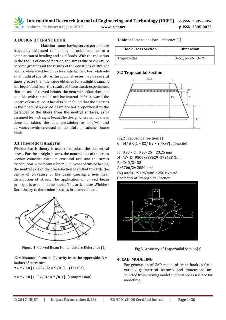
3.1 Theoretical Analysis
Winkler batch theory is used to calculate the theoretical
stress. For the straight beams, the neutral axis of the cross
section coincides with its censorial axis and the stress
distribution in the beam is liner. But in case of curved beams,
the neutral axis of the cross-section is shifted towards the
centre of curvature of the beam causing a non-linear
distribution of stress. The application of curved beam
principle is used in crane hooks. This article uses Winkler-
Bach theory to determine stresses in a curved beam.
Figure 1: Curved Beam Nomenclature Reference [1]
d2 = Distance of center of gravity from the upper side. R =
Radius of curvature
σ = M/ AR [1 + R2/ H2 × Y /R+Y] ..(Tensile)
σ = M/ AR [1 - R2/ H2 × Y /R-Y] ..(Compression)
Table 1: Dimensions For Reference [1]
Hook Cross Section Dimension
Trapozoidal B=51, b= 26 , D=75
3.2 Trapozoidal Section :
Fig.2 Trapozoidal Section[1]
σ = M/ AR [1 + R2/ H2 × Y /R+Y] ..(Tensile)
H= 0.93 × C =0.93×25 = 23.25 mm
M= W× R= 9806×888629=372628 Nmm
R= C+ D/2= 38
A=5700/2= 2850mm2
(6t) total= 194 N/mm2 ≤ 250 N/mm2
Geometry of Trapozoidal Section
Fig.3 Geometry of Trapozoidal Section[3]
4. CAD MODELING For generation of CAD model of crane hook in Catia
various geometrical features and dimensions are
selected from existing model and best one is selected for
modelling .
International Research Journal of Engineering and Technology (IRJET) e-ISSN: 2395 -0056
Volume: 04 Issue: 01 | Jan -2017 www.irjet.net p-ISSN: 2395-0072
© 2017, IRJET | Impact Factor value: 5.181 | ISO 9001:2008 Certified Journal | Page 1431
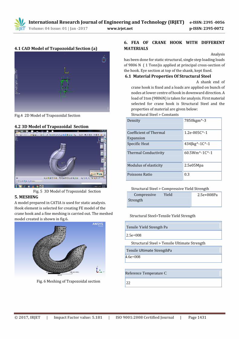
4.1 CAD Model of Trapozoidal Section (a)
Fig.4 2D Model of Trapozoidal Section
4.2 3D Model of Trapozoidal Section
Fig. 5 3D Model of Trapozoidal Section
5. MESHING
A model prepared in CATIA is used for static analysis.
Hook element is selected for creating FE model of the
crane hook and a fine meshing is carried out. The meshed
model created is shown in fig.6.
Fig. 6 Meshing of Trapozoidal section
6. FEA OF CRANE HOOK WITH DIFFERENT
MATERIALS
Analysis
has been done for static structural, single step loading loads
of 9806 N ( 1 Tonn)is applied at principal cross-section of
the hook. Eye section at top of the shank, kept fixed.
6.1 Material Properties Of Structural Steel A shank end of
crane hook is fixed and a loads are applied on bunch of
nodes at lower centre of hook in downward direction. A
load of 1ton (9806N) is taken for analysis. First material
selected for crane hook is Structural Steel and the
properties of material are given below:
Structural Steel > Constants
Density 7850kgm^-3
Coefficient of Thermal
Expansion
1.2e-005C^-1
Specific Heat 434Jkg^-1C^-1
Thermal Conductivity 60.5Wm^-1C^-1
Modulus of elasticity 2.5e05Mpa
Poissons Ratio 0.3
Structural Steel > Compressive Yield Strength
Compressive Yield
Strength
trtrengthPa
2.5e+008Pa
Structural Steel>Tensile Yield Strength
Structural Steel > Tensile Ultimate Strength
Reference Temperature C
22
Tensile Ultimate StrengthPa
4.6e+008
Tensile Yield Strength Pa
2.5e+008
International Research Journal of Engineering and Technology (IRJET) e-ISSN: 2395 -0056
Volume: 04 Issue: 01 | Jan -2017 www.irjet.net p-ISSN: 2395-0072
© 2017, IRJET | Impact Factor value: 5.181 | ISO 9001:2008 Certified Journal | Page 1432
Chemical Composition of Structural Steel
Element Content (%)
Vanadium,V 0.03-0.08
Carbon, C 0.15-0.30
Phosphorus,P 0.04-0.05
Silicon, S 0.02-0.4
Nickel,N 0.25-1.25
Mangnese, Mn 0.50-1.70
Maximum Nodes = 12180
Maximum Nodes = 7499
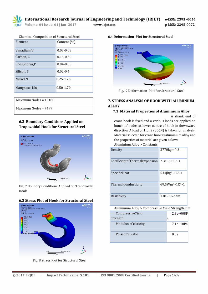
6.2 Boundary Conditions Applied on
Trapozoidal Hook for Structural Steel
Fig. 7 Boundry Conditions Applied on Trapozoidal
Hook
6.3 Stress Plot of Hook for Structural Steel
Fig. 8 Stress Plot for Structural Steel
6.4 Deformation Plot for Structural Steel
Fig. 9 Deformation Plot For Structural Steel
7. STRESS ANALYSIS OF HOOK WITH ALUMINIUM
ALLOY
7.1 Material Properties of Aluminium Alloy A shank end of
crane hook is fixed and a various loads are applied on
bunch of nodes at lower centre of hook in downward
direction. A load of 1ton (9806N) is taken for analysis.
Material selected for crane hook is aluminium alloy and
the properties of material are given below:
Aluminium Alloy > Constants
Density
2770kgm^-3
CoefficientofThermalExpansion 2.3e-005C^-1
SpecificHeat 534Jkg^-1C^-1
ThermalConductivity 69.5Wm^-1C^-1
Resistivity 1.8e-007ohm
Aluminium Alloy > Compressive Yield Strength,E,m
CompressiveYield
Strength
trtrengthPa
2.8e+008P
a
Modulus of elsticity
trtrengthPa
7.1e+10Pa
Poisson's Ratio 0.32
International Research Journal of Engineering and Technology (IRJET) e-ISSN: 2395 -0056
Volume: 04 Issue: 01 | Jan -2017 www.irjet.net p-ISSN: 2395-0072
© 2017, IRJET | Impact Factor value: 5.181 | ISO 9001:2008 Certified Journal | Page 1433
Aluminium Alloy >TensileYieldStrength
Aluminium Alloy > Tensile Ultimate Strength
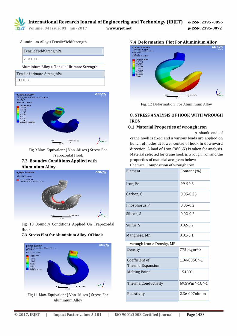
Fig.9 Max. Equivalent ( Von -Mises ) Stress For
Trapozoidal Hook
7.2 Boundry Conditions Applied with
Aluminium Alloy
Fig. 10 Boundry Conditions Applied On Trapozoidal
Hook
7.3 Stress Plot for Aluminium Alloy Of Hook
Fig.11 Max. Equivalent ( Von -Mises ) Stress For
Aluminium Alloy
7.4 Deformation Plot For Aluminium Alloy
Fig. 12 Deformation For Aluminium Alloy
8. STRESS ANALYSIS OF HOOK WITH WROUGH
IRON
8.1 Material Properties of wrough iron
A shank end of
crane hook is fixed and a various loads are applied on
bunch of nodes at lower centre of hook in downward
direction. A load of 1ton (9806N) is taken for analysis.
Material selected for crane hook is wrough iron and the
properties of material are given below:
Chemical Composition of wrough iron
Element Content (%)
Iron, Fe 99-99.8
Carbon, C 0.05-0.25
Phosphorus,P 0.05-0.2
Silicon, S 0.02-0.2
Sulfur, S 0.02-0.2
Mangnese, Mn 0.01-0.1
wrough iron > Density, MP
Density 7750kgm^-3
Coefficient of
ThermalExpansion
1.3e-005C^-1
Melting Point 15400C
ThermalConductivity 69.5Wm^-1C^-1
Resistivity 2.3e-007ohmm
Tensile Ultimate StrengthPa
3.1e+008
TensileYieldStrengthPa
2.8e+008
International Research Journal of Engineering and Technology (IRJET) e-ISSN: 2395 -0056
Volume: 04 Issue: 01 | Jan -2017 www.irjet.net p-ISSN: 2395-0072
© 2017, IRJET | Impact Factor value: 5.181 | ISO 9001:2008 Certified Journal | Page 1434
wrough iron > Modulus of Elasticity, Poisson's Ratio
Modulus of
elsticity
trtrengthPa
1.93e+008Pa
Poisson's Ratio 0.278
wrough iron > Yield Strength
Yield Strength
trtrengthPa
2.29e+008Pa
wrough iron > Tensile Yield Strength
Tensile Yield
Strength
trtrengthPa
2.34e+008Pa
CompressiveYiel
d Strength
2.8e+008Pa
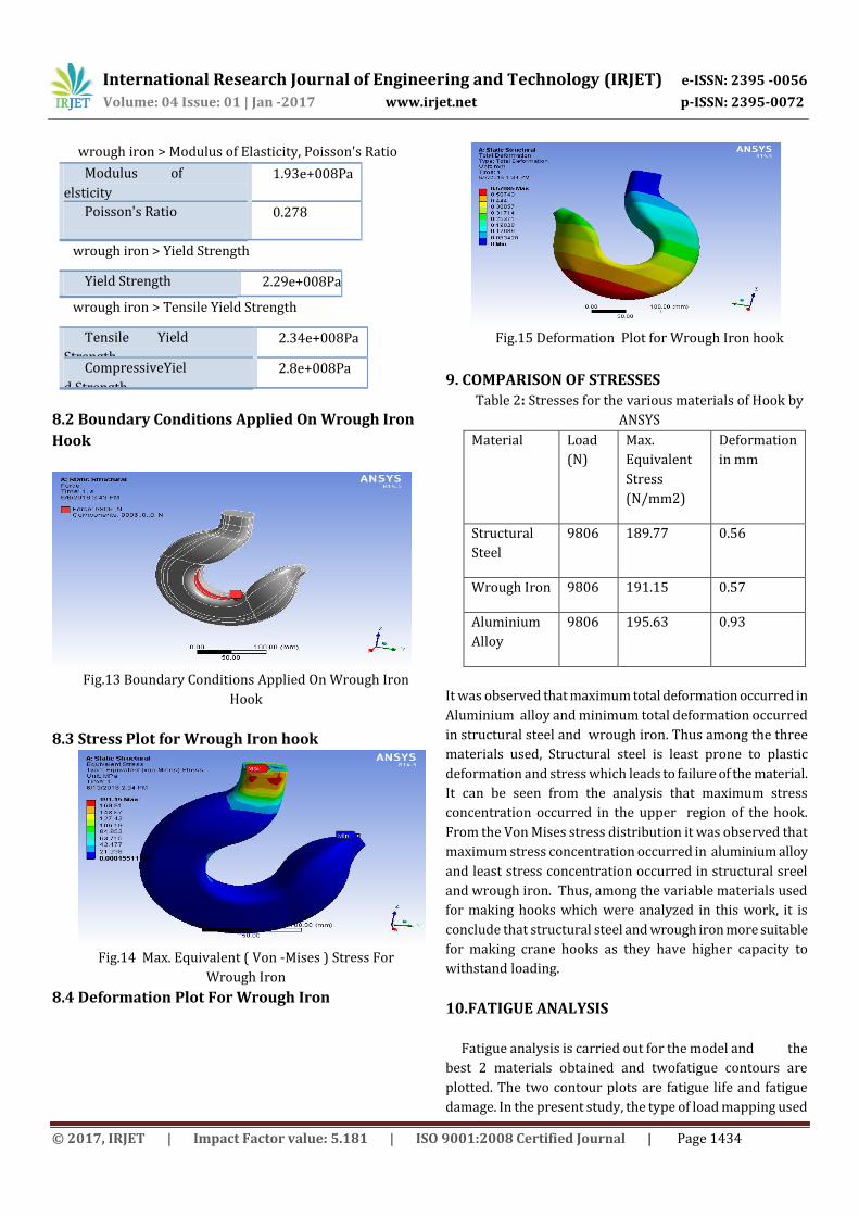
8.2 Boundary Conditions Applied On Wrough Iron
Hook
Fig.13 Boundary Conditions Applied On Wrough Iron
Hook
8.3 Stress Plot for Wrough Iron hook
Fig.14 Max. Equivalent ( Von -Mises ) Stress For
Wrough Iron
8.4 Deformation Plot For Wrough Iron
Fig.15 Deformation Plot for Wrough Iron hook
9. COMPARISON OF STRESSES
Table 2: Stresses for the various materials of Hook by
ANSYS
Material
Load
(N)
Max.
Equivalent
Stress
(N/mm2)
Deformation
in mm
Structural
Steel
9806 189.77 0.56
Wrough Iron 9806 191.15 0.57
Aluminium
Alloy
9806 195.63 0.93
It was observed that maximum total deformation occurred in
Aluminium alloy and minimum total deformation occurred
in structural steel and wrough iron. Thus among the three
materials used, Structural steel is least prone to plastic
deformation and stress which leads to failure of the material.
It can be seen from the analysis that maximum stress
concentration occurred in the upper region of the hook.
From the Von Mises stress distribution it was observed that
maximum stress concentration occurred in aluminium alloy
and least stress concentration occurred in structural sreel
and wrough iron. Thus, among the variable materials used
for making hooks which were analyzed in this work, it is
conclude that structural steel and wrough iron more suitable
for making crane hooks as they have higher capacity to
withstand loading.
10.FATIGUE ANALYSIS
Fatigue analysis is carried out for the model and the
best 2 materials obtained and twofatigue contours are
plotted. The two contour plots are fatigue life and fatigue
damage. In the present study, the type of load mapping used
International Research Journal of Engineering and Technology (IRJET) e-ISSN: 2395 -0056
Volume: 04 Issue: 01 | Jan -2017 www.irjet.net p-ISSN: 2395-0072
© 2017, IRJET | Impact Factor value: 5.181 | ISO 9001:2008 Certified Journal | Page 1435
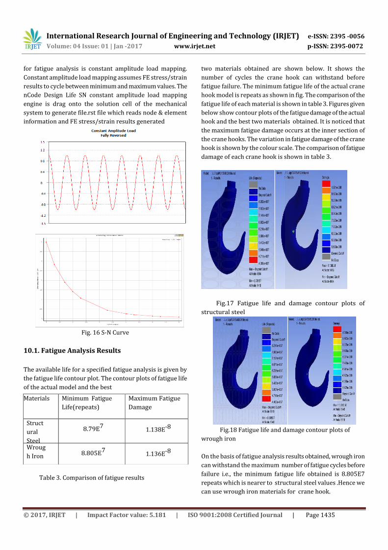
for fatigue analysis is constant amplitude load mapping.
Constant amplitude load mapping assumes FE stress/strain
results to cycle between minimum and maximum values. The
nCode Design Life SN constant amplitude load mapping
engine is drag onto the solution cell of the mechanical
system to generate file.rst file which reads node & element
information and FE stress/strain results generated
Fig. 16 S-N Curve
10.1. Fatigue Analysis Results
The available life for a specified fatigue analysis is given by
the fatigue life contour plot. The contour plots of fatigue life
of the actual model and the best
Table 3. Comparison of fatigue results
two materials obtained are shown below. It shows the
number of cycles the crane hook can withstand before
fatigue failure. The minimum fatigue life of the actual crane
hook model is repeats as shown in fig. The comparison of the
fatigue life of each material is shown in table 3. Figures given
below show contour plots of the fatigue damage of the actual
hook and the best two materials obtained. It is noticed that
the maximum fatigue damage occurs at the inner section of
the crane hooks. The variation in fatigue damage of the crane
hook is shown by the colour scale. The comparison of fatigue
damage of each crane hook is shown in table 3.
Fig.17 Fatigue life and damage contour plots of
structural steel
Fig.18 Fatigue life and damage contour plots of
wrough iron
On the basis of fatigue analysis results obtained, wrough iron
can withstand the maximum number of fatigue cycles before
failure i.e., the minimum fatigue life obtained is 8.805E7
repeats which is nearer to structural steel values .Hence we
can use wrough iron materials for crane hook.
Materials Minimum Fatigue
Life(repeats)
Maximum Fatigue
Damage
Struct
ural
Steel
8.79E7 1.138E-8
Wroug
h Iron 8.805E7 1.136E-8
International Research Journal of Engineering and Technology (IRJET) e-ISSN: 2395 -0056
Volume: 04 Issue: 01 | Jan -2017 www.irjet.net p-ISSN: 2395-0072
© 2017, IRJET | Impact Factor value: 5.181 | ISO 9001:2008 Certified Journal | Page 1436
CONCLUSION
The results of stress analysis calculated from FEA
analysis for various different material such as Structural
Steel ,Wrougt iron, Aluminium Alloy. For the different
Material, It is observed that keeping the tone are same
with different Material topology we will get different
results, but from the above table it is found that the
Structural Steel and Wrough Iron gives minimum stress
.Further Fatigue analysis was done on the materials
from that it is found that wrough iron can withstand the
maximum number of fatigue cycles before failure.
Hence we can use wrough iron materials for crane hook.
FUTURE SCOPE
Further it is advisable to conduct photo
elasticity test for the crane hook under investigation in
order to get better insight for stress concentration.
Material saving approach by optimization of cross
section area with consideration of stress concentration
can be also done to put away manufacturing cost.
REFERENCES
[1] Sayyedkasim Ali1, Harish Kumar2, Stress Analysis of
Crane Hook with Different Cross Section Using Finite
Element Method, IndiaIndex Copernicus Value (2013): 6.14 |
Impact Factor (2013): 4.438
[2] Yogesh Tripathi1, U.K Joshi2 IJRET: International Journal
of Research in Engineering and Technology eISSN: 2319-
1163 | pISSN: 2321-7308 Comparison of stress between
Winkler-Bach theory and Ansys Finite Element Method for
crane hook with a Trapezoidal cross-section
[3] Patel Ravin B, Patel Bhakti K., (may 2014) ISSN:2319-
7900 design and analysis of crane hook with different
material
[4] Amandeep Singh, Vinod Rohilla (IJMECH) Vol.4, No.4,
November optimization and Fatigue Analysis of a crane hook
using Finite Element Method
BIBLOGRAPHY
Ms. Mamta R. Zade P.G. Student
at Dept. of Mechanical Engg.
GSMCOE Balewadi Pune-45.She
has received the Bachelor of
Engineering. in Mechanical
branch from the Nagpur
University , India, in 2012
Specialization/ Interested Area:
Design Engg.
EmailAdress:
Recommended