Semester- 6, Division-C
Guided by,Prof. H.H. Jariwala
L.D. College of Engineering, Ahmedabad-15
Filtration [Water and Wastewater Engineering]
2
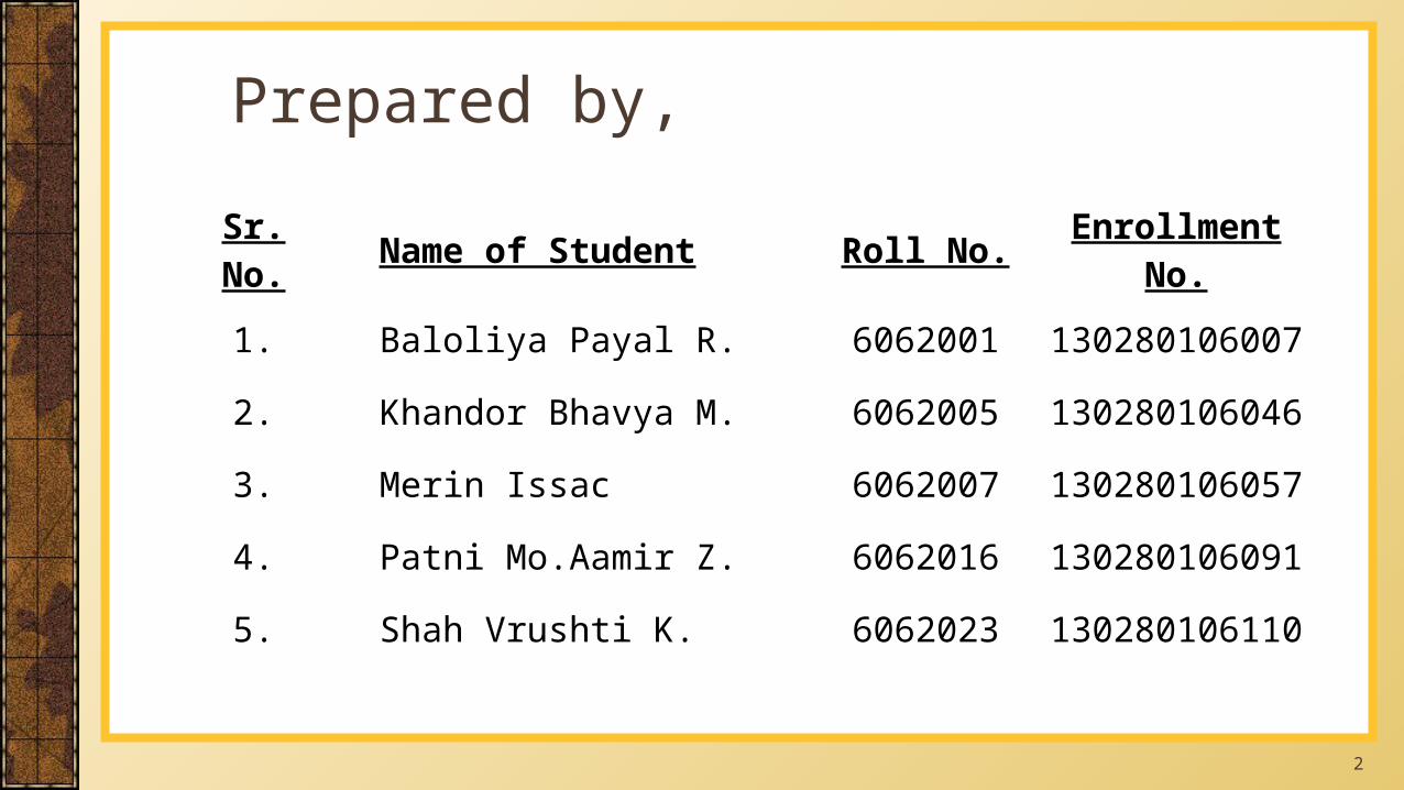
Prepared by,
Sr. No. Name of Student Roll No. Enrollment No.
1. Baloliya Payal R. 6062001 130280106007
2. Khandor Bhavya M. 6062005 130280106046
3. Merin Issac 6062007 130280106057
4. Patni Mo.Aamir Z. 6062016 130280106091
5. Shah Vrushti K. 6062023 130280106110
3
ContentSr. No. Topic Slide No.
1. Introduction [04-05]2. Theory of filter [06-10]3. Filter materials [11-15]4. Classification of Filters [16-16]5. Slow Sand Filter [17-28]6. Rapid Sand Filter [29-40]7. Backwashing [41-45]8. Comparison of SSF & RSF [46-47]9. Design of Rapid Sand Filter [48-53]
4
Sedimentation removes a large percentages of settable solids,
suspended solids, organic matter and small percentage of bacteria.
But water still contains fine suspended solids, microorganisms and
color(if present).
To remove these impurities, still further and to produce potable and
palatable water, the water is filtered through the beds of granular
materials like sand and gravel.
Introduction
5
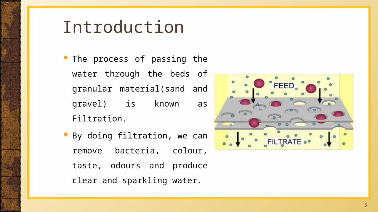
The process of passing the water
through the beds of granular
material(sand and gravel) is known
as Filtration.
By doing filtration, we can remove
bacteria, colour, taste, odours and
produce clear and sparkling water.
Introduction
6
When water is filtered through the bed of filter media, usually
consisting of clean sand, the following factors take place:
◦ (1) Mechanical straining
◦ (2) Sedimentation
◦ (3) Biological action &
◦ (4) Electrolytic action
Theory of filter
7
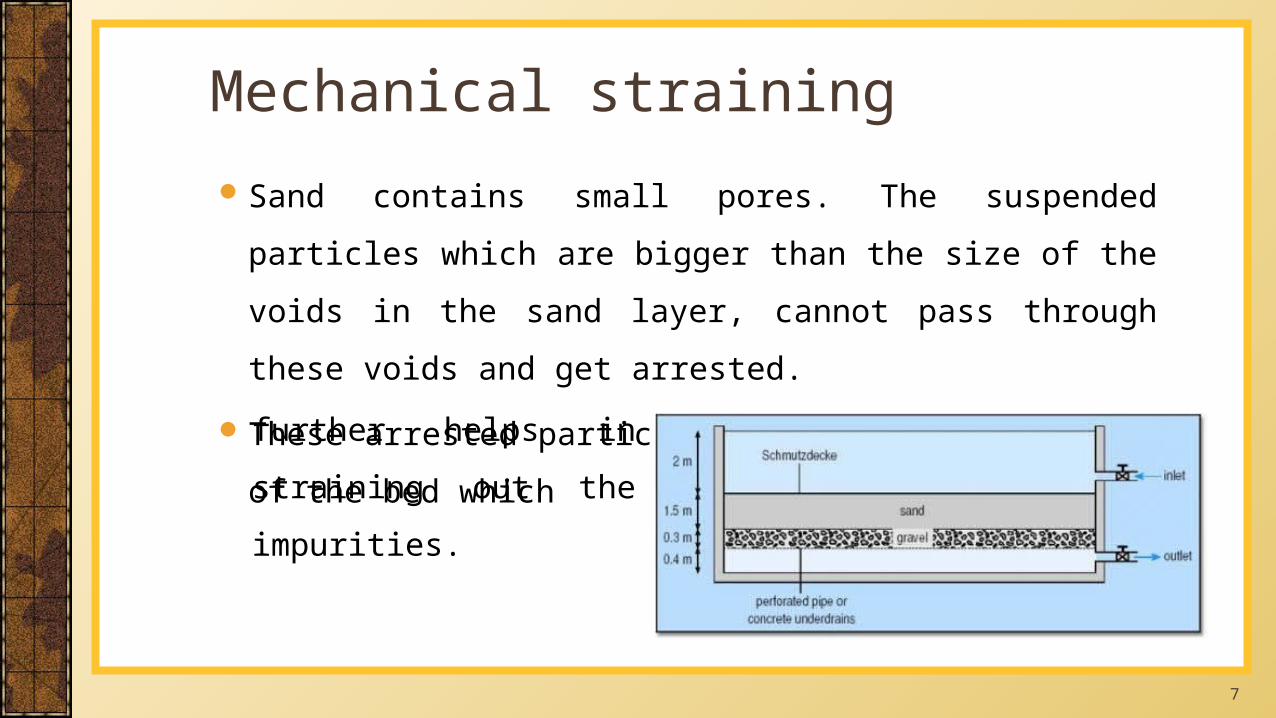
Mechanical strainingSand contains small pores. The suspended particles which are bigger
than the size of the voids in the sand layer, cannot pass through these
voids and get arrested.
These arrested particles forms a mat on the top of the bed which
further helps in straining out
the impurities.
8
In mechanical straining only those particles which are coarser than
void size are arrested. Finer particles are removed by sedimentation.
The voids between sand grains of filter acts like small sedimentation
tanks.
The colloidal matter arrested in the voids is the gelatinous mass and
therefore attract other finer particles.
Sedimentation
9
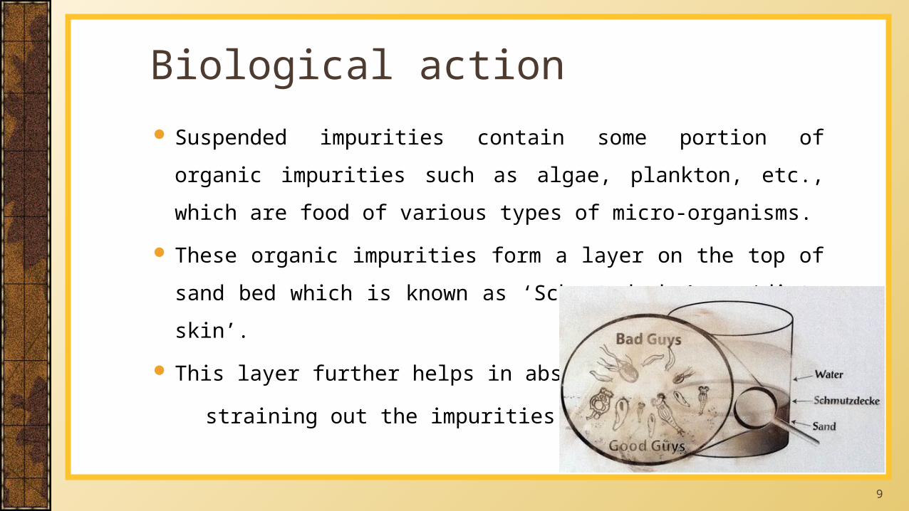
Suspended impurities contain some portion of organic impurities such
as algae, plankton, etc., which are food of various types of micro-
organisms.
These organic impurities form a layer on the top of sand bed which is
known as ‘Schmutzdecke’ or ‘dirty skin’.
This layer further helps in absorbing and
straining out the impurities.
Biological action
10
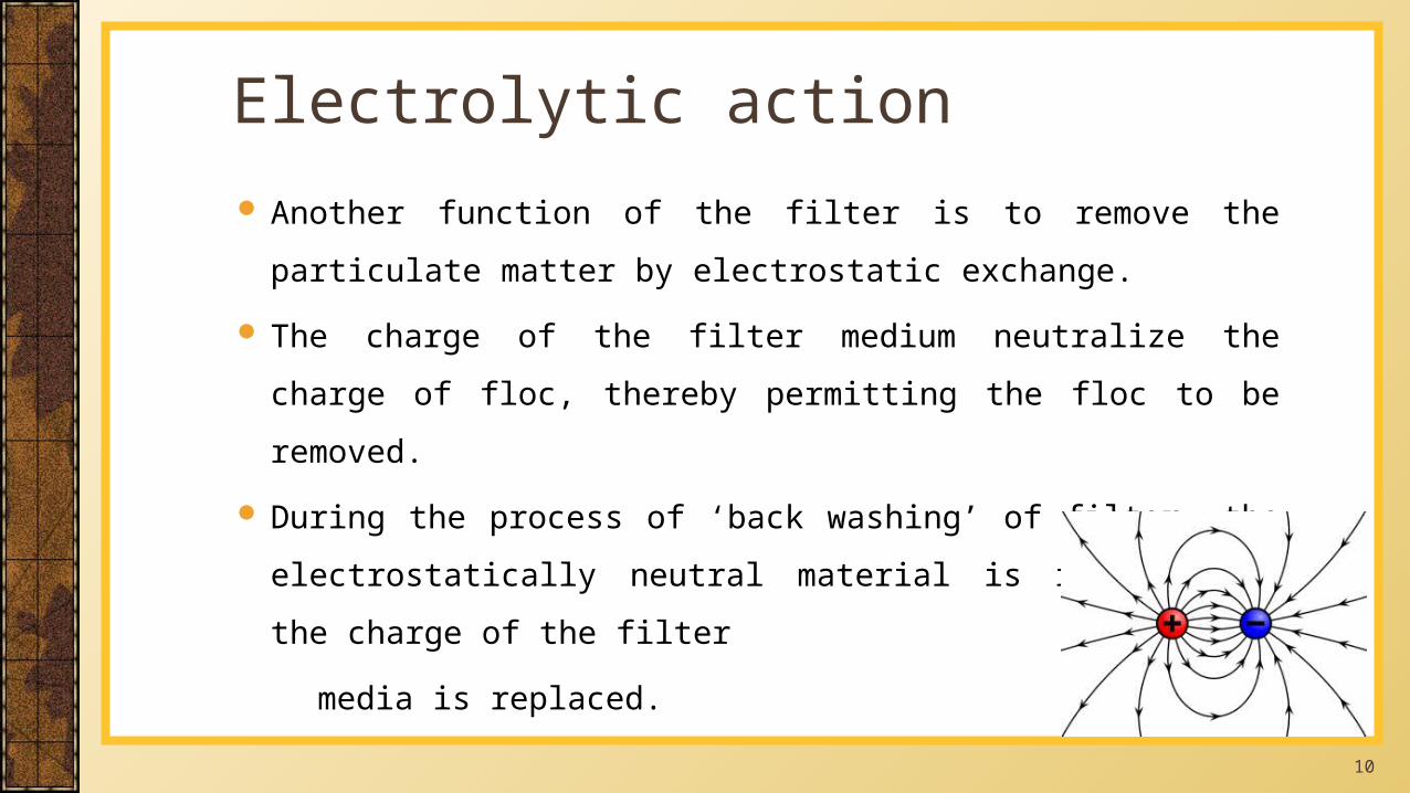
Another function of the filter is to remove the particulate matter by
electrostatic exchange.
The charge of the filter medium neutralize the charge of floc, thereby
permitting the floc to be removed.
During the process of ‘back washing’ of filter, the electrostatically
neutral material is removed and the charge of the filter
media is replaced.
Electrolytic action
11
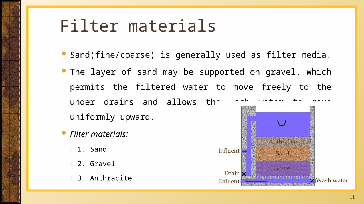
Sand(fine/coarse) is generally used as filter media.
The layer of sand may be supported on gravel, which permits the
filtered water to move freely to the under drains and allows the wash
water to move uniformly upward.
Filter materials:
◦ 1. Sand
◦ 2. Gravel
◦ 3. Anthracite
Filter materials
12
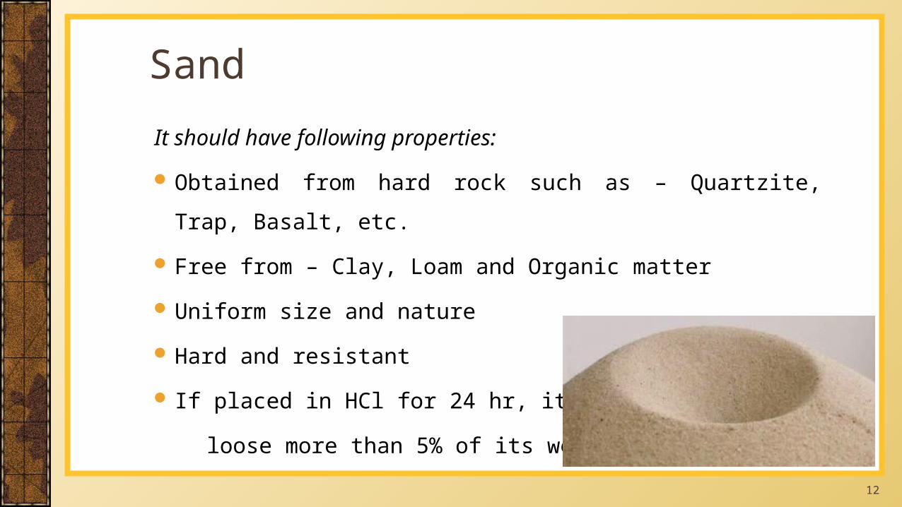
It should have following properties:
Obtained from hard rock such as – Quartzite, Trap, Basalt, etc.
Free from – Clay, Loam and Organic matter
Uniform size and nature
Hard and resistant
If placed in HCl for 24 hr, it should not
loose more than 5% of its weight.
Sand
13
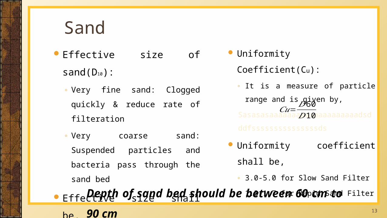
Uniformity Coefficient(Cu):
◦ It is a measure of particle range and is
given by,
Sasasasaaaaaaaaaaaaaaaaaaaadsd
ddfsssssssssssssssds
Uniformity coefficient shall be,
◦ 3.0-5.0 for Slow Sand Filter
◦ 1.3-1.7 for Rapid Sand Filter
SandEffective size of sand(D10):
◦ Very fine sand: Clogged quickly &
reduce rate of filteration
◦ Very coarse sand: Suspended particles
and bacteria pass through the sand bed
Effective size shall be,
0.20-0.30 mm for Slow Sand Filter
0.45-0.70 mm for Rapid Sand Filter
Depth of sand bed should be between 60 cm to 90 cm
𝐶𝑢=𝐷60𝐷10
14
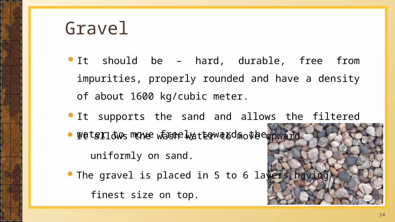
It should be – hard, durable, free from impurities, properly rounded
and have a density of about 1600 kg/cubic meter.
It supports the sand and allows the filtered water to move freely
towards the underdrains.
Gravel
It allows the wash water to move upward
uniformly on sand.
The gravel is placed in 5 to 6 layers having
finest size on top.
15
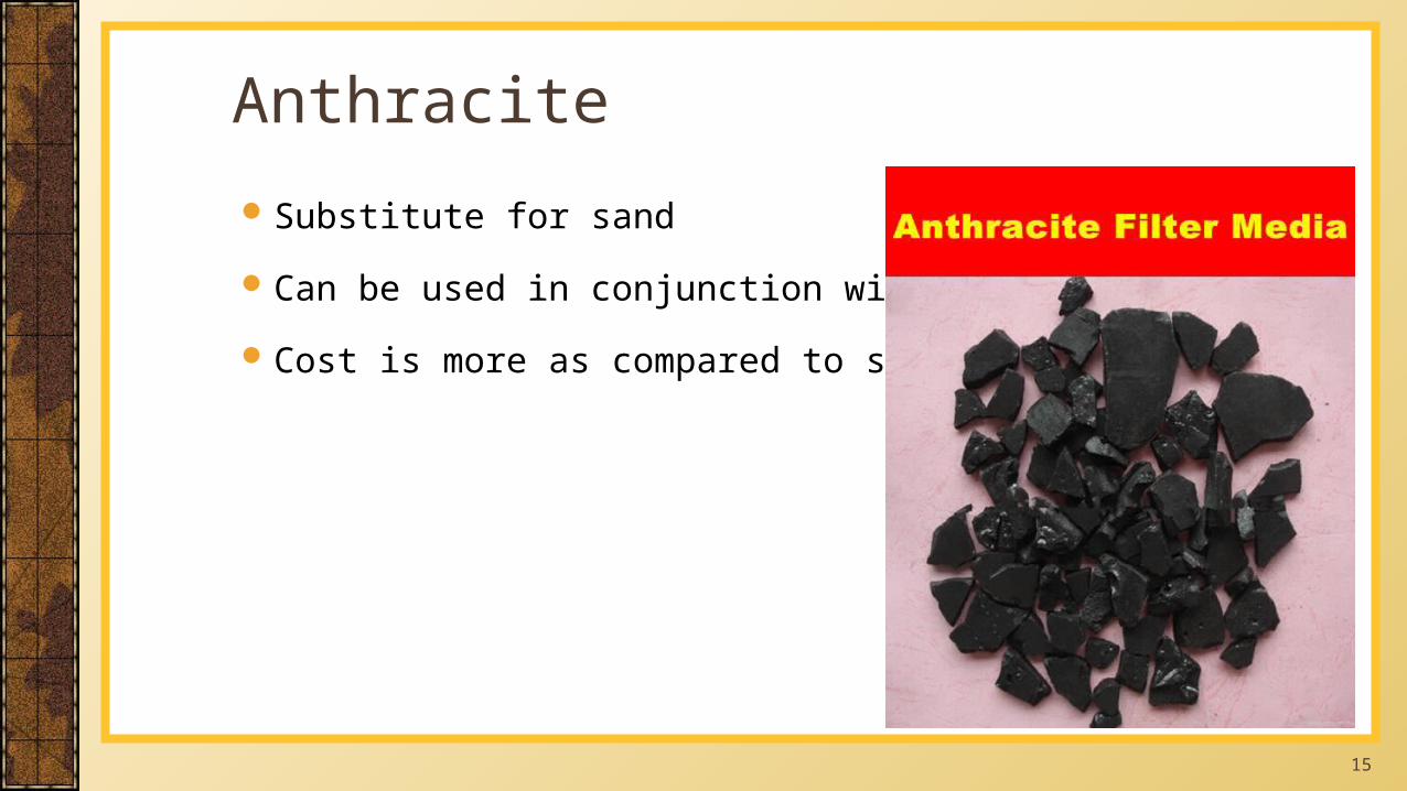
Substitute for sand
Can be used in conjunction with sand
Cost is more as compared to sand
Anthracite
16
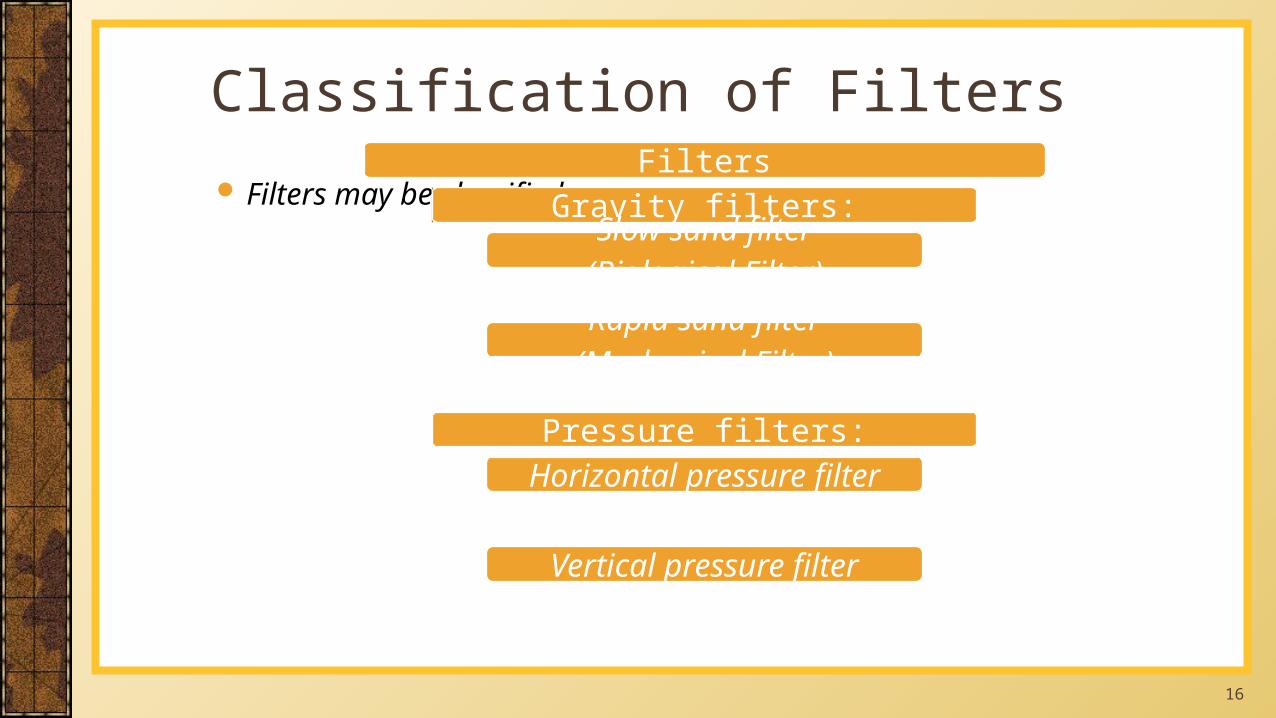
Filters may be classified as:
Classification of FiltersFilters
Gravity filters:Slow sand filter
(Biological Filter)
Rapid sand filter(Mechanical Filter)
Pressure filters:Horizontal pressure filter
Vertical pressure filter
17
Used in rural areas in place of a rapid gravity filter
Filtration rate is 50 to 100 times slower than that of a rapid gravity
filter (0.1 to 0.3 m/hour - 0.2 m/hr is the typical rate)
Used for the removal of turbidity (colloidal particles), suspended
solids and pathogens
Replaces the coagulation-flocculation-settling, the filtration and the
disinfection by chlorination treatments in rural areas
Slow Sand Filter
18
Filtered water has < 0.3 NTU turbidity (the goal is < 0.1 NTU)
Output water may require chlorination (for quality improvement)
A pre-treatment in roughing filters may be needed specially when the
turbidity is high (greater than 20-50 NTU)
Oxfam filters (use of geo-textile fabric on the top of the sand layer for
straining out the suspended matter (pre-treatment!)
Slow Sand Filter
19
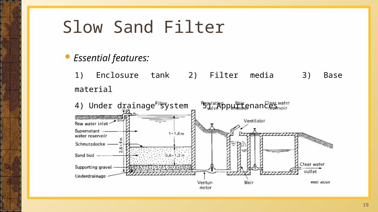
Slow Sand FilterEssential features:
1) Enclosure tank 2) Filter media 3) Base material
4) Under drainage system 5) Appurtenances
20
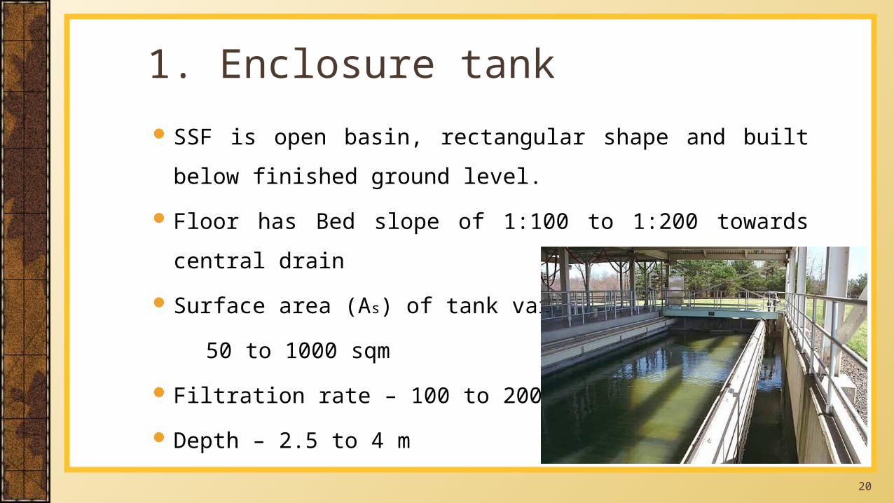
SSF is open basin, rectangular shape and built below finished ground
level.
Floor has Bed slope of 1:100 to 1:200 towards central drain
Surface area (As) of tank varies from
50 to 1000 sqm
Filtration rate – 100 to 200 lit/sqm/hr.
Depth – 2.5 to 4 m
1. Enclosure tank
21
Thickness of sand layer - 90 to 110 cm
Effective size – 0.20 to 0.35 (Common value -0.3)
Coefficient of uniformity – 2.0 to 3.0 (Common value - 2.5)
2. Filter media: Sand
22
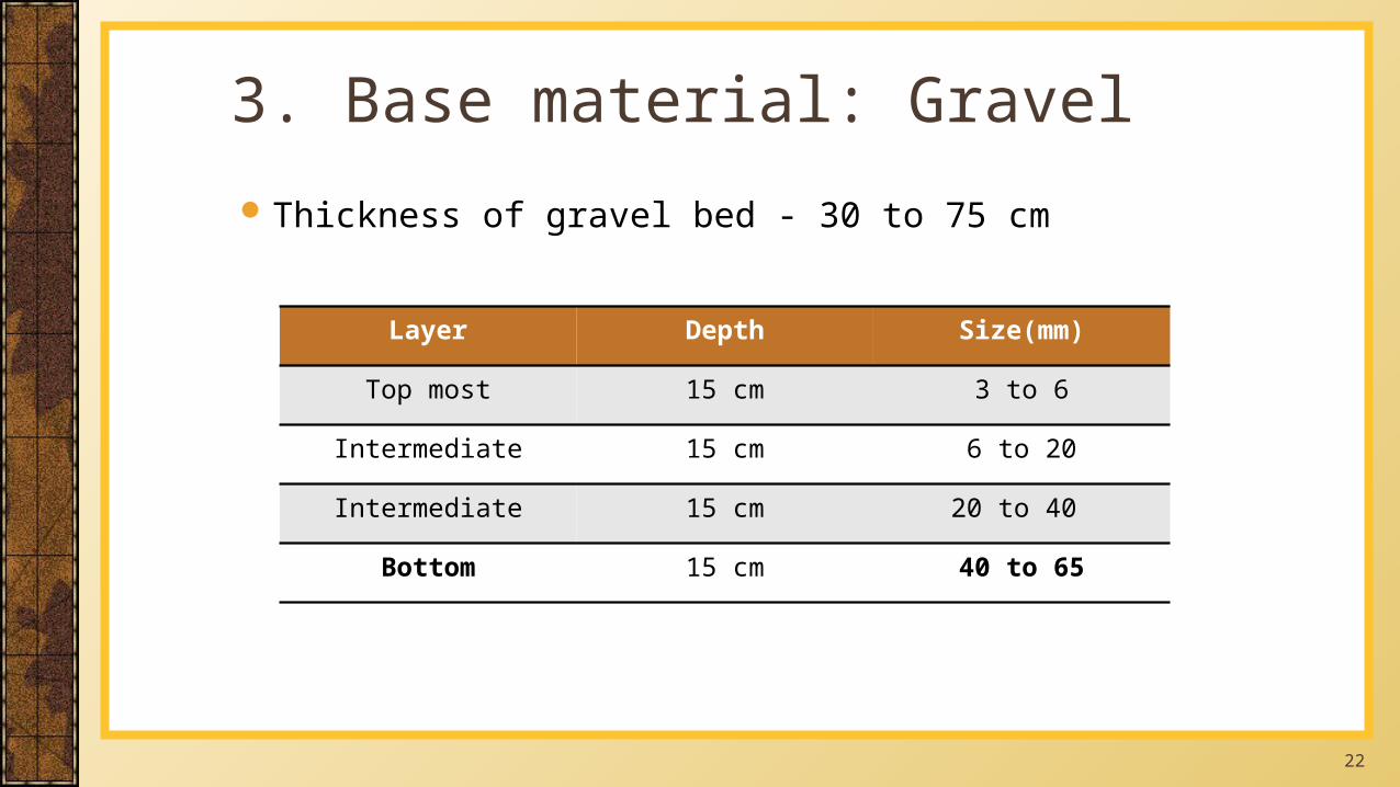
Thickness of gravel bed - 30 to 75 cm
3. Base material: Gravel
Layer Depth Size(mm)
Top most 15 cm 3 to 6
Intermediate 15 cm 6 to 20
Intermediate 15 cm 20 to 40
Bottom 15 cm 40 to 65
23
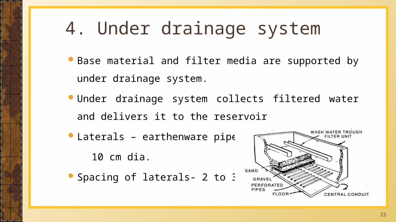
Base material and filter media are supported by under drainage
system.
Under drainage system collects filtered water and delivers it to the
reservoir
Laterals – earthenware pipes of 7.5 to
10 cm dia.
Spacing of laterals- 2 to 3 m c/c
4. Under drainage system
24
Devices are required for
Gauge – to measure loss of head
Vertical air vent pipe – for proper functioning of filtering layers
Telescopic tube – to maintain constant discharge
A meter – to measure flow
5. Appurtenances
25
In a slow sand filter impurities in the water are removed by a
combination of processes: sedimentation, straining, adsorption, and
chemical and bacteriological action.
During the first few days, water is purified mainly by mechanical and
physical-chemical processes. The resulting accumulation of sediment
and organic matter forms a thin layer on the sand surface, which
remains permeable and retains particles even smaller than the spaces
between the sand grains.
Working of Slow Sand Filter
26
As this layer (referred to as “Schmutzdecke”) develops, it becomes
living quarters of vast numbers of micro-organisms which break down
organic material retained from the water, converting it into water,
carbon dioxide and other oxides.
Most impurities, including bacteria and viruses, are removed from the
raw water as it passes through the filter skin and the layer of filter bed
sand just below.
Working of Slow Sand Filter(contd..)
27
The purification mechanisms extend from the filter skin to approx.
0.3-0.4 m below surface of filter bed, gradually decreasing in activity
at lower-levels as water becomes pure & contains less organic matter.
When the micro-organisms become well established, the filter will
work efficiently and produce high quality effluent which is virtually
free of disease carrying organisms and biodegradable organic matter.
They are suitable for treating waters with low colors, low turbidities
and low bacterial contents.
Working of Slow Sand Filter(contd..)
28
Disadvantages:
Old fashioned and outdated
method of water purification
(but still in use)
Initial cost is low but
maintenance cost is much more
than rapid sand filter
These filters need a lot of space
Advantages:
Simple to construct and operate
Cheaper
Physical, Chemical and
Bacteriological quality of water
is very high
Reduces bacterial count by
99.9% & E. coli by 99%
Advantages & Disadvantages of SSF
29
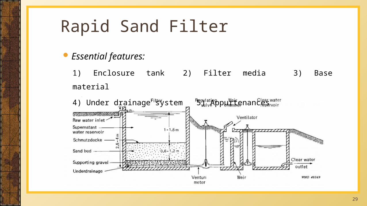
Rapid Sand FilterEssential features:
1) Enclosure tank 2) Filter media 3) Base material
4) Under drainage system 5) Appurtenances
30
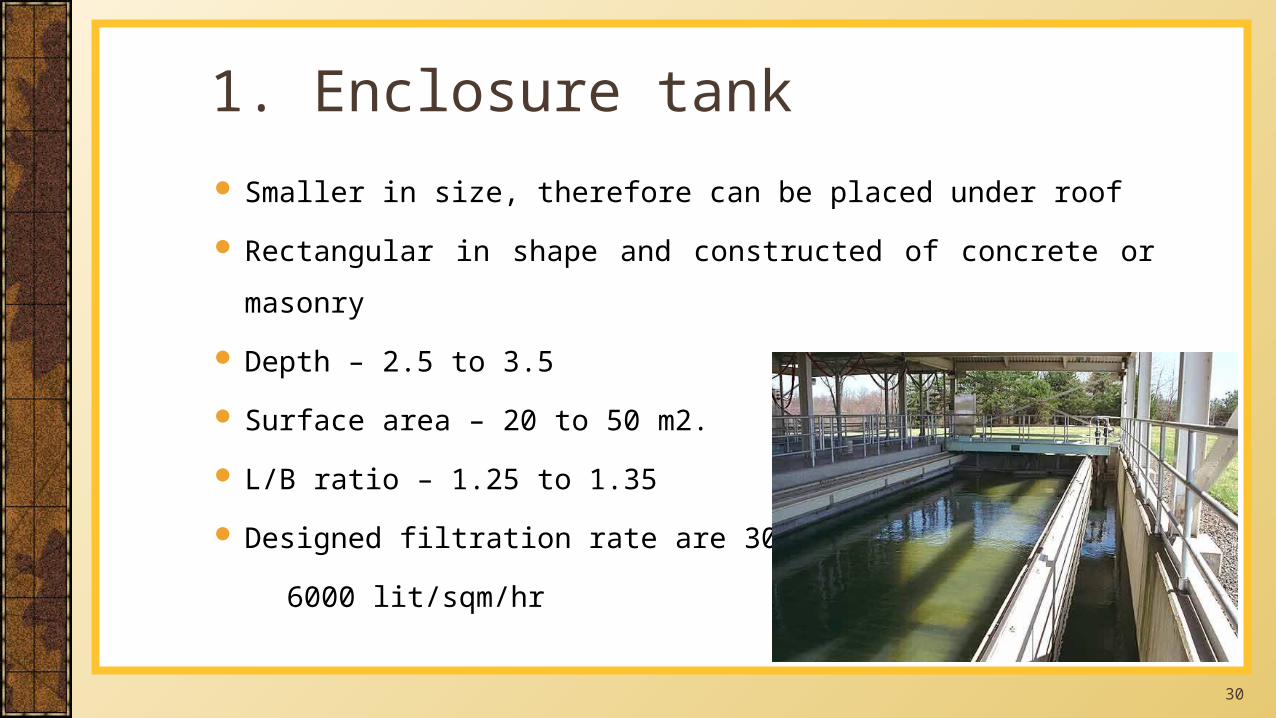
Smaller in size, therefore can be placed under roof
Rectangular in shape and constructed of concrete or masonry
Depth – 2.5 to 3.5
Surface area – 20 to 50 m2.
L/B ratio – 1.25 to 1.35
Designed filtration rate are 3000 to
6000 lit/sqm/hr
1. Enclosure tank
31
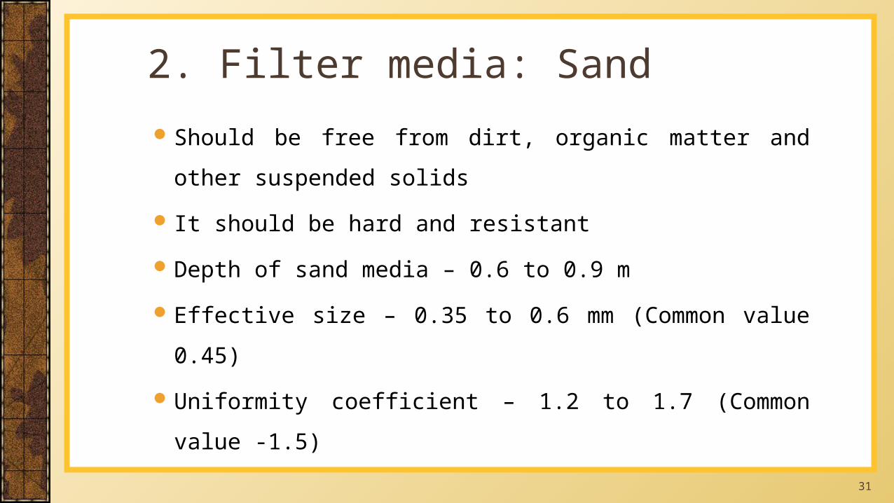
Should be free from dirt, organic matter and other suspended solids
It should be hard and resistant
Depth of sand media – 0.6 to 0.9 m
Effective size – 0.35 to 0.6 mm (Common value 0.45)
Uniformity coefficient – 1.2 to 1.7 (Common value -1.5)
2. Filter media: Sand
32
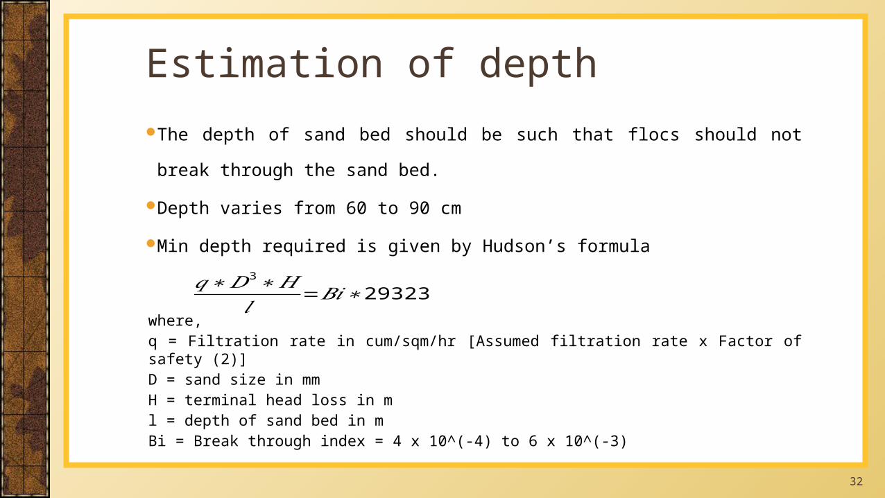
The depth of sand bed should be such that flocs should not break through the sand
bed.
Depth varies from 60 to 90 cm
Min depth required is given by Hudson’s formula
where,q = Filtration rate in cum/sqm/hr [Assumed filtration rate x Factor of safety (2)]D = sand size in mmH = terminal head loss in ml = depth of sand bed in mBi = Break through index = 4 x 10^(-4) to 6 x 10^(-3)
Estimation of depth
𝑞∗𝐷3∗𝐻𝑙 =𝐵𝑖∗29323
33
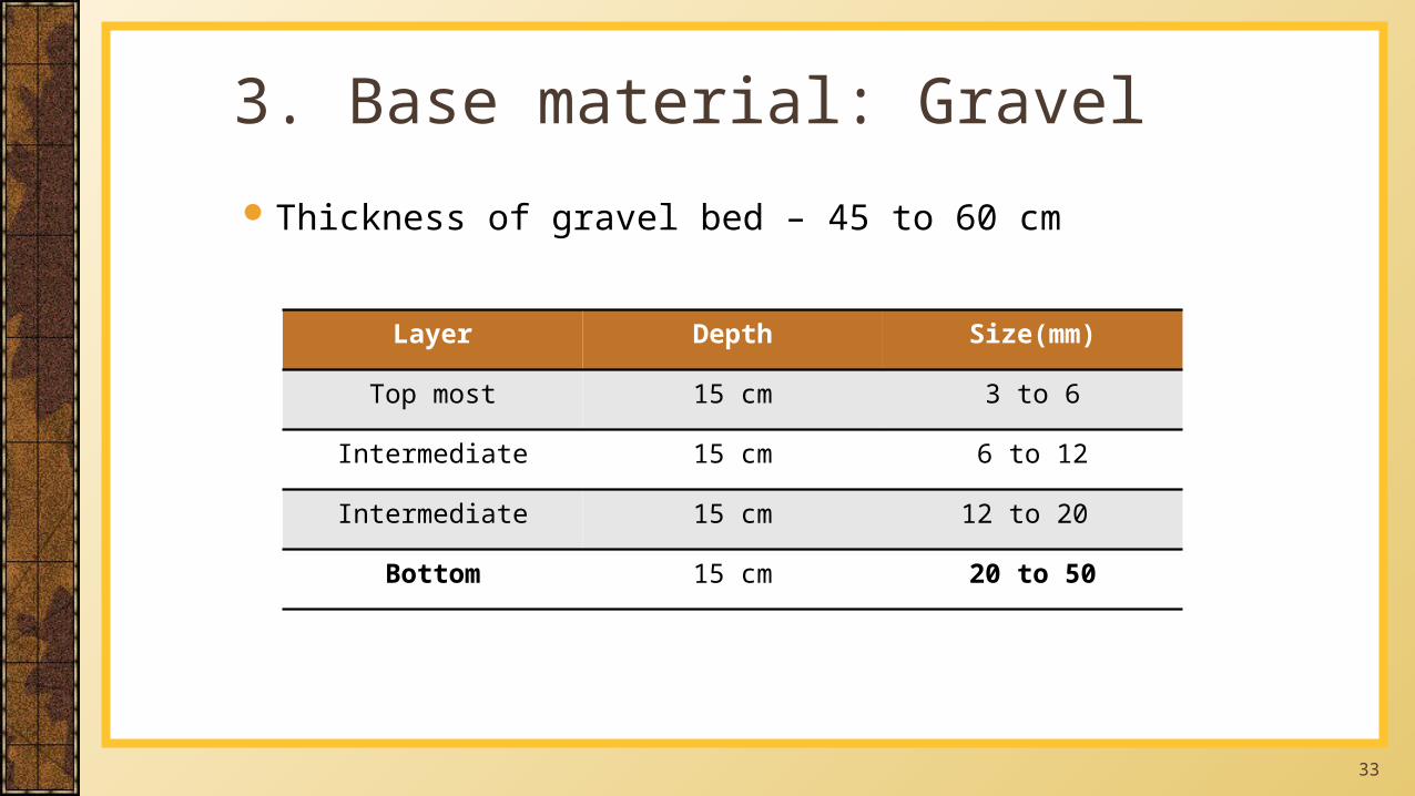
Thickness of gravel bed – 45 to 60 cm
3. Base material: Gravel
Layer Depth Size(mm)
Top most 15 cm 3 to 6
Intermediate 15 cm 6 to 12
Intermediate 15 cm 12 to 20
Bottom 15 cm 20 to 50
34
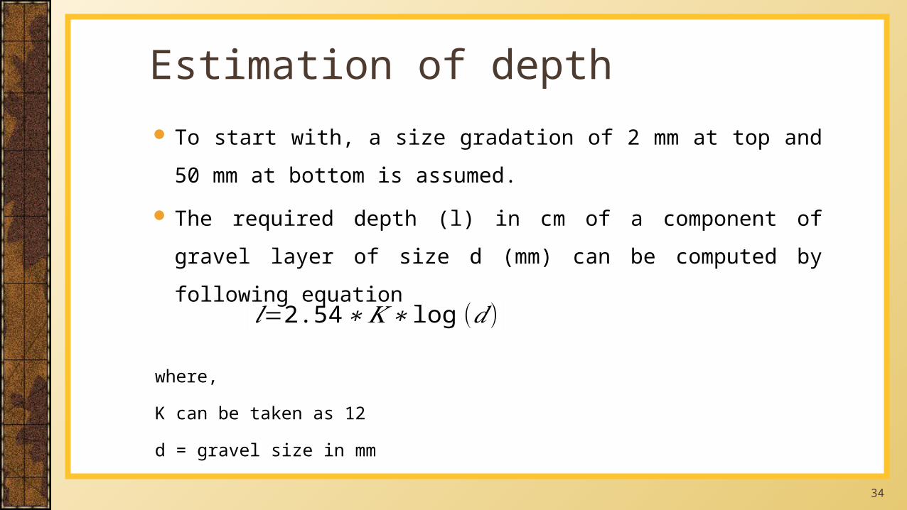
To start with, a size gradation of 2 mm at top and 50 mm at bottom is
assumed.
The required depth (l) in cm of a component of gravel layer of size d
(mm) can be computed by following equation
where,
K can be taken as 12
d = gravel size in mm
Estimation of depth
𝑙=2.54∗𝐾∗ log (𝑑 )
35
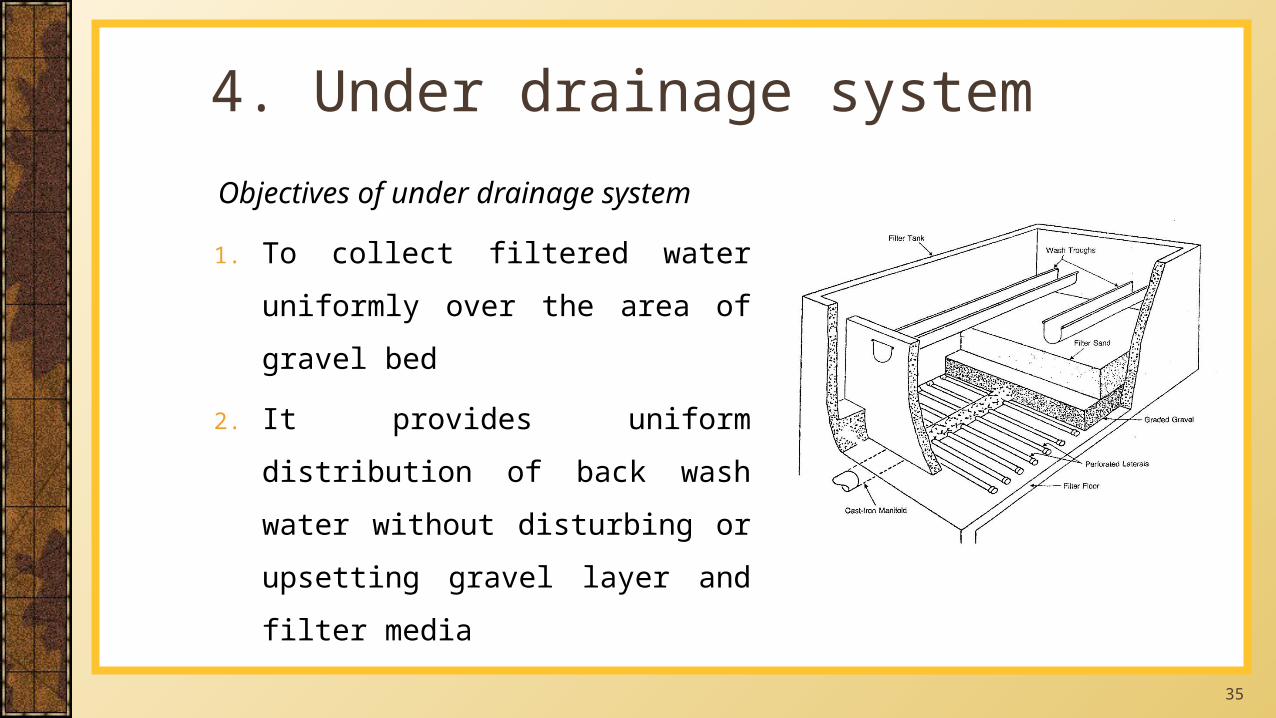
Objectives of under drainage system
1. To collect filtered water uniformly
over the area of gravel bed
2. It provides uniform distribution of
back wash water without disturbing
or upsetting gravel layer and filter
media
4. Under drainage system
36
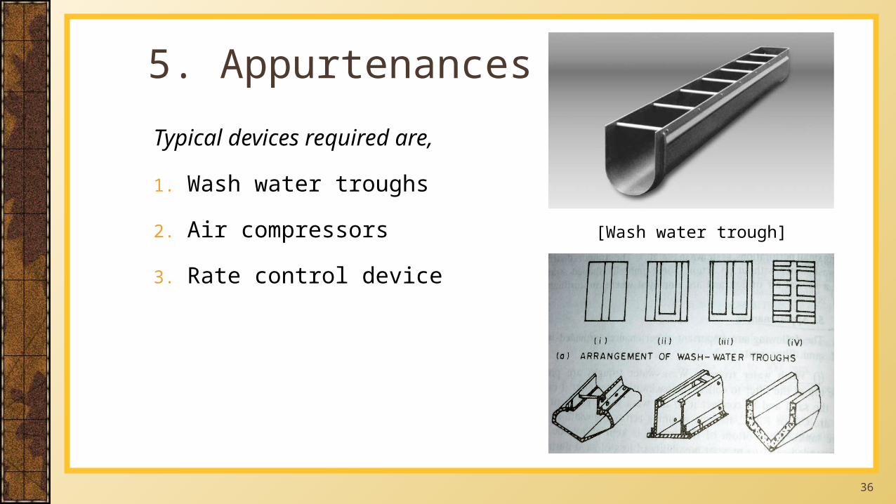
Typical devices required are,
1. Wash water troughs
2. Air compressors
3. Rate control device
5. Appurtenances
[Wash water trough]
37
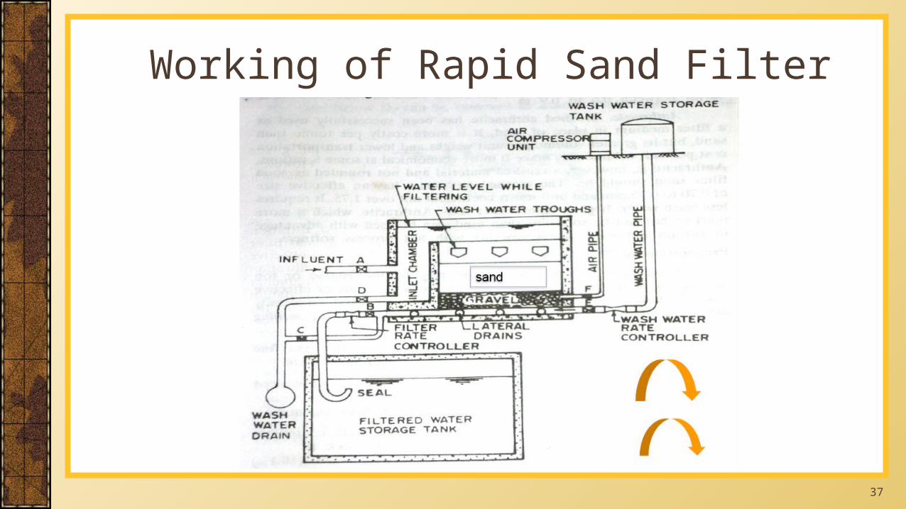
Working of Rapid Sand Filter
38
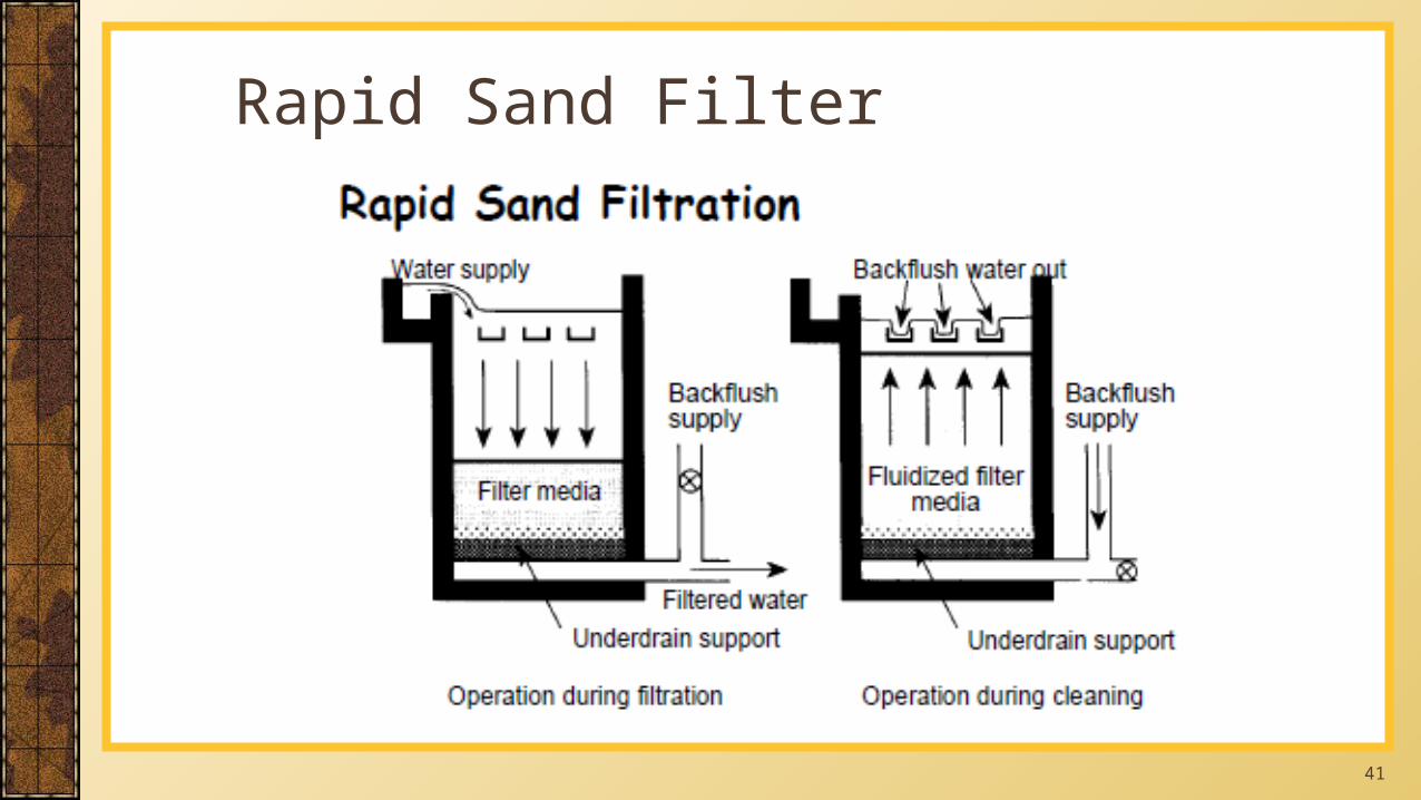
All valves are kept closed except valves A and B
Valve A is opened to permit water from clarifier
Valve B is opened to carry filtered water to clear water sump
Head of 2m over sand bed is maintained
Designed filtration rate are 3000 to 6000 lit/sqm/hr
Filter run depends on quality of feed water
Working of Rapid Sand Filter
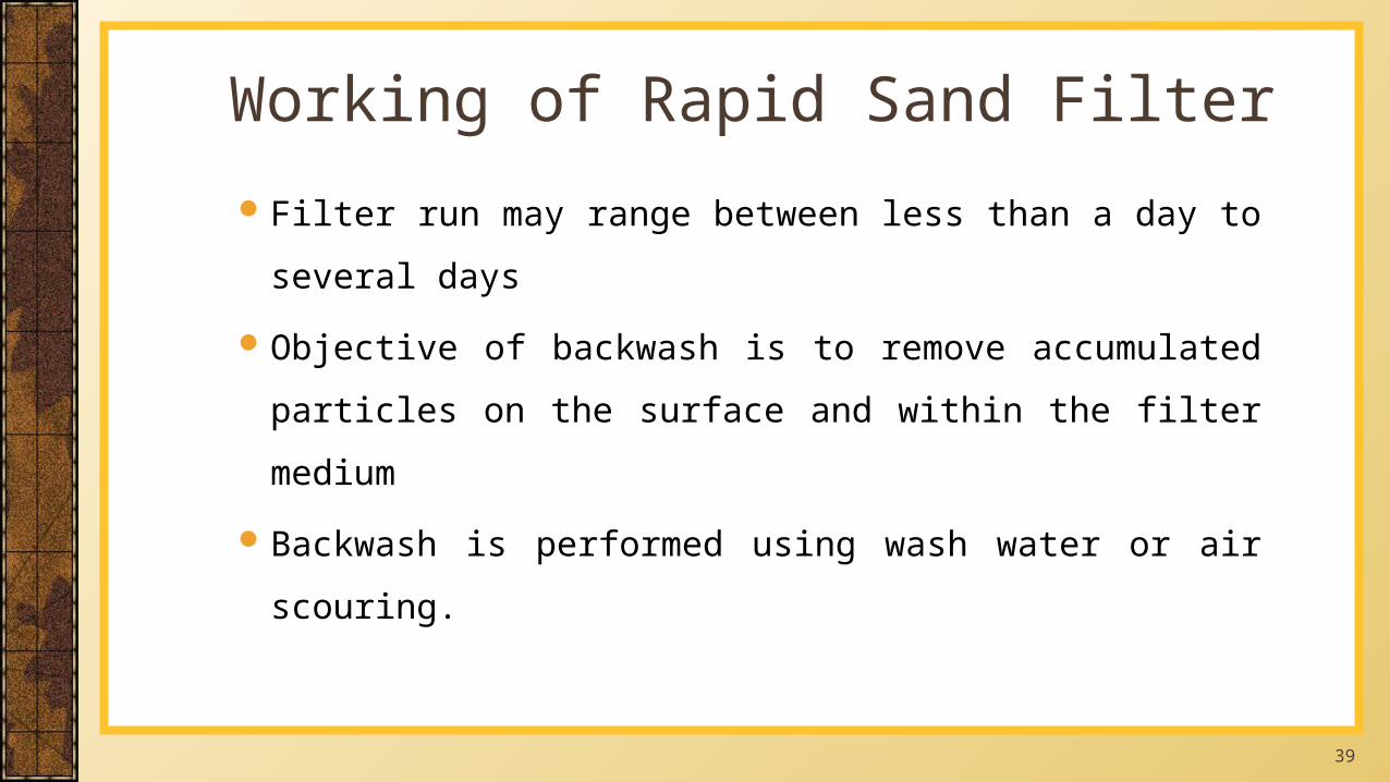
39
Filter run may range between less than a day to several days
Objective of backwash is to remove accumulated particles on the
surface and within the filter medium
Backwash is performed using wash water or air scouring.
Working of Rapid Sand Filter
40
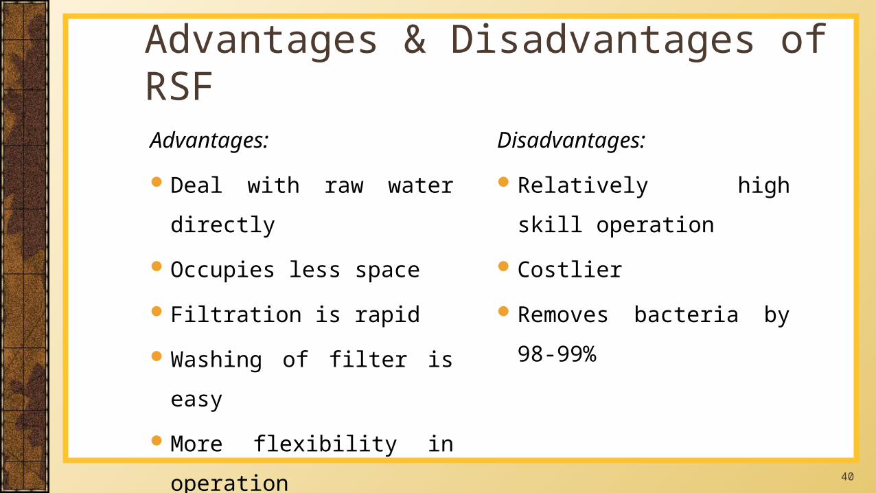
Disadvantages:
Relatively high skill operation
Costlier
Removes bacteria by 98-99%
Advantages:
Deal with raw water directly
Occupies less space
Filtration is rapid
Washing of filter is easy
More flexibility in operation
Advantages & Disadvantages of RSF
41
Rapid Sand Filter
42
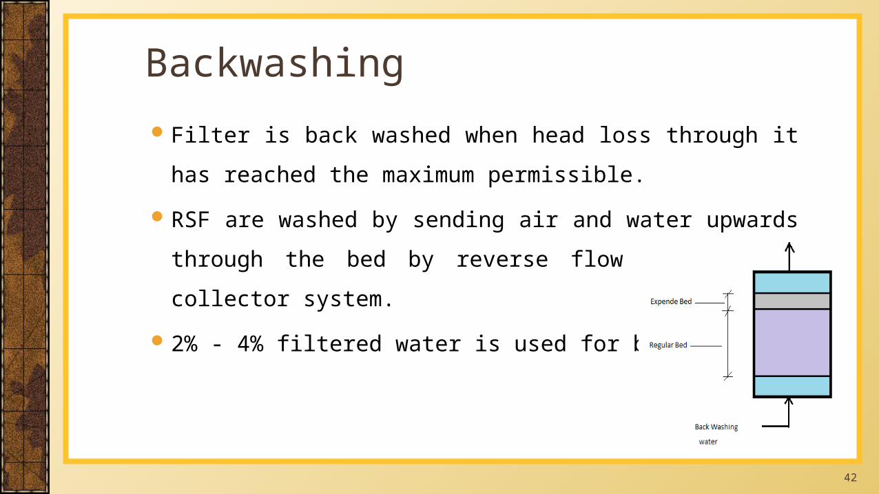
Filter is back washed when head loss through it has reached the
maximum permissible.
RSF are washed by sending air and water upwards through the bed by
reverse flow through the collector system.
2% - 4% filtered water is used for backwashing
Backwashing
43
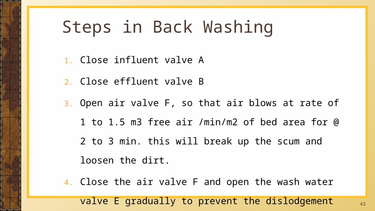
1. Close influent valve A
2. Close effluent valve B
3. Open air valve F, so that air blows at rate of 1 to 1.5 m3 free air
/min/m2 of bed area for @ 2 to 3 min. this will break up the scum
and loosen the dirt.
4. Close the air valve F and open the wash water valve E gradually to
prevent the dislodgement of finer gravel.
Steps in Back Washing
44
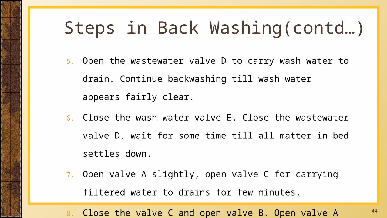
5. Open the wastewater valve D to carry wash water to drain. Continue
backwashing till wash water appears fairly clear.
6. Close the wash water valve E. Close the wastewater valve D. wait for some
time till all matter in bed settles down.
7. Open valve A slightly, open valve C for carrying filtered water to drains for
few minutes.
8. Close the valve C and open valve B. Open valve A completely to resume
normal filtration
Steps in Back Washing(contd…)
45
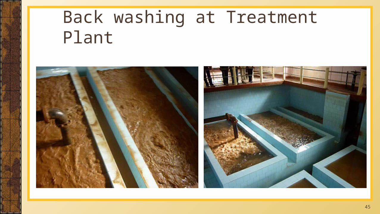
Back washing at Treatment Plant
46
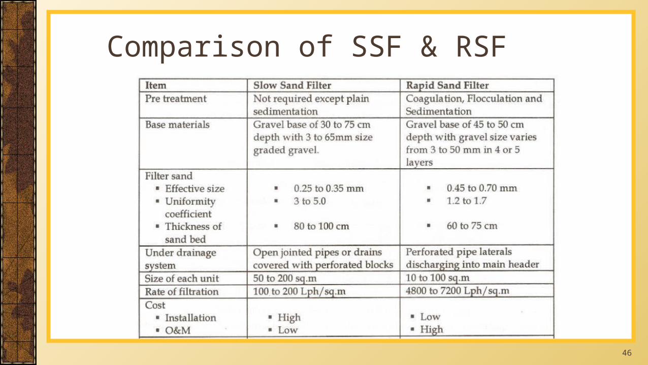
Comparison of SSF & RSF
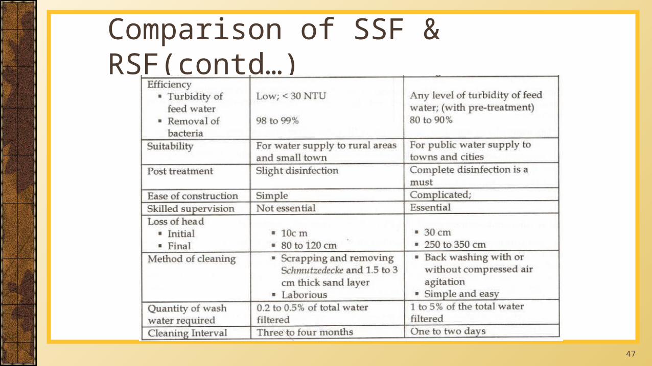
47
Comparison of SSF & RSF(contd…)
48
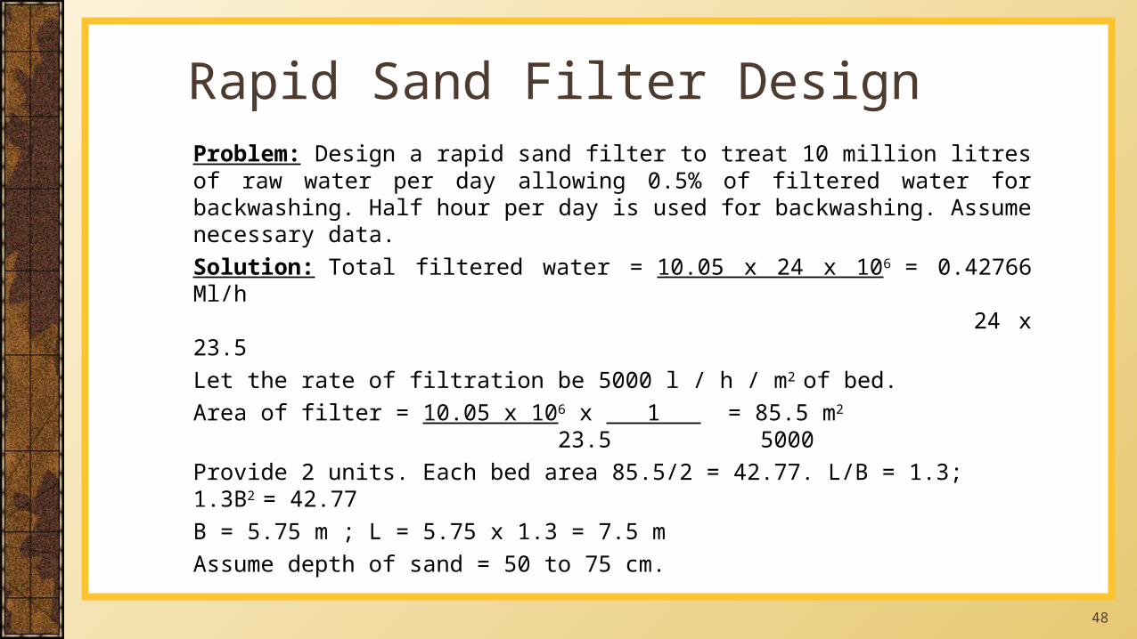
Problem: Design a rapid sand filter to treat 10 million litres of raw water per day allowing 0.5% of filtered water for backwashing. Half hour per day is used for backwashing. Assume necessary data.Solution: Total filtered water = 10.05 x 24 x 106 = 0.42766 Ml/h 24 x 23.5Let the rate of filtration be 5000 l / h / m2 of bed.Area of filter = 10.05 x 106 x 1 = 85.5 m2 23.5 5000Provide 2 units. Each bed area 85.5/2 = 42.77. L/B = 1.3; 1.3B2 = 42.77B = 5.75 m ; L = 5.75 x 1.3 = 7.5 mAssume depth of sand = 50 to 75 cm.
Rapid Sand Filter Design
49
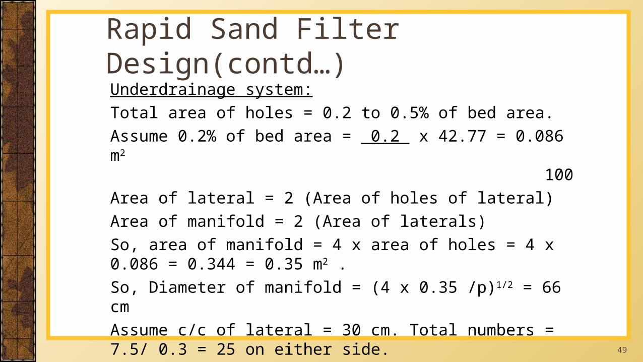
Underdrainage system:Total area of holes = 0.2 to 0.5% of bed area.Assume 0.2% of bed area = 0.2 x 42.77 = 0.086 m2
100Area of lateral = 2 (Area of holes of lateral)Area of manifold = 2 (Area of laterals)So, area of manifold = 4 x area of holes = 4 x 0.086 = 0.344 = 0.35 m2 .So, Diameter of manifold = (4 x 0.35 /p)1/2 = 66 cmAssume c/c of lateral = 30 cm. Total numbers = 7.5/ 0.3 = 25 on either side.
Rapid Sand Filter Design(contd…)
50
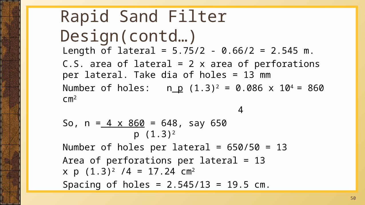
Length of lateral = 5.75/2 - 0.66/2 = 2.545 m.C.S. area of lateral = 2 x area of perforations per lateral. Take dia of holes = 13 mmNumber of holes: n p (1.3)2 = 0.086 x 104 = 860 cm2
4 So, n = 4 x 860 = 648, say 650 p (1.3)2
Number of holes per lateral = 650/50 = 13Area of perforations per lateral = 13 x p (1.3)2 /4 = 17.24 cm2
Spacing of holes = 2.545/13 = 19.5 cm.
Rapid Sand Filter Design(contd…)
51
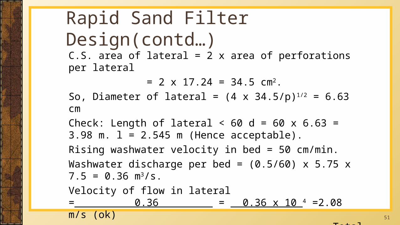
C.S. area of lateral = 2 x area of perforations per lateral = 2 x 17.24 = 34.5 cm2.
So, Diameter of lateral = (4 x 34.5/p)1/2 = 6.63 cmCheck: Length of lateral < 60 d = 60 x 6.63 = 3.98 m. l = 2.545 m (Hence acceptable).Rising washwater velocity in bed = 50 cm/min.Washwater discharge per bed = (0.5/60) x 5.75 x 7.5 = 0.36 m3/s.Velocity of flow in lateral = 0.36 = 0.36 x 10 4 =2.08 m/s (ok) Total lateral area 50 x 34.5Manifold velocity = 0.36 = 1.04 m/s < 2.25 m/s (ok) 0.345
Rapid Sand Filter Design(contd…)
52
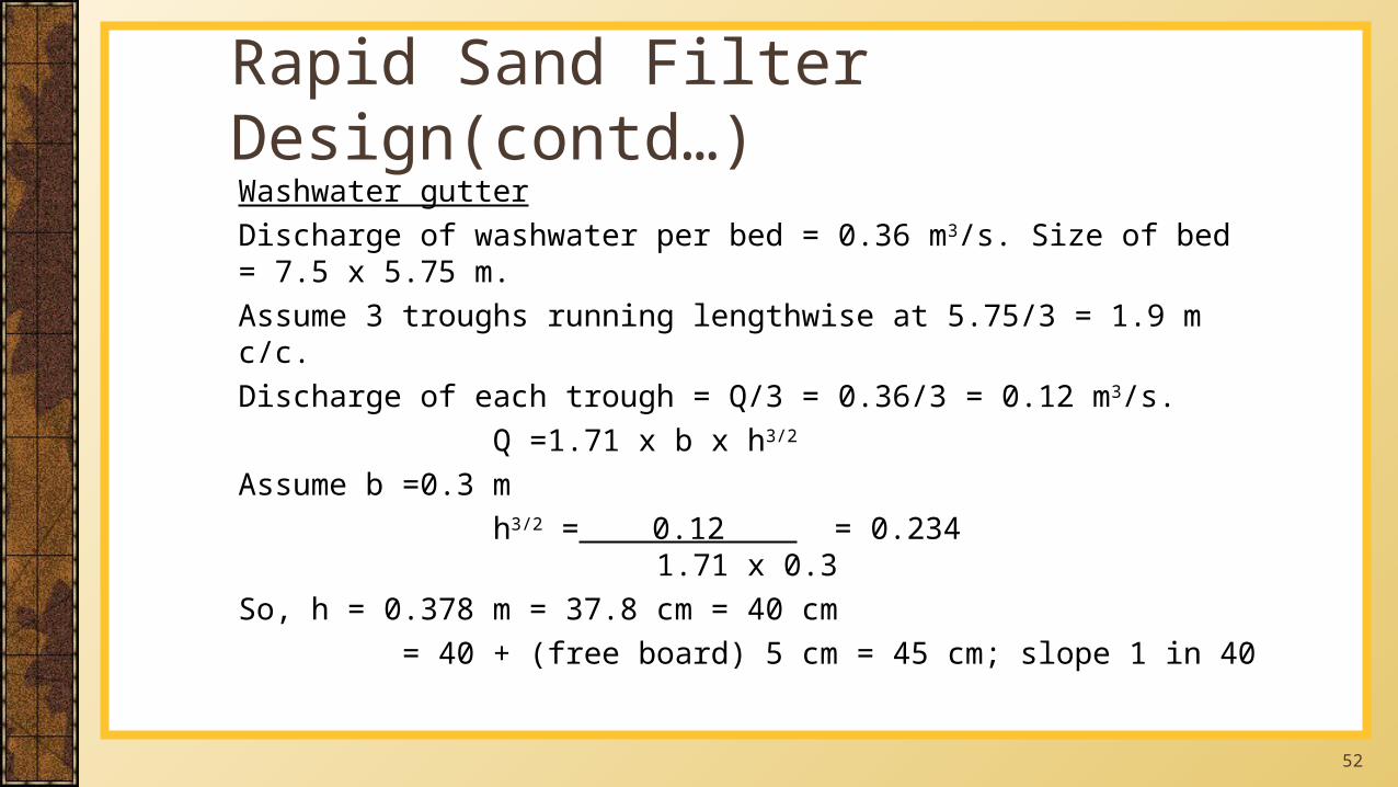
Washwater gutterDischarge of washwater per bed = 0.36 m3/s. Size of bed = 7.5 x 5.75 m.Assume 3 troughs running lengthwise at 5.75/3 = 1.9 m c/c.Discharge of each trough = Q/3 = 0.36/3 = 0.12 m3/s. Q =1.71 x b x h3/2
Assume b =0.3 m h3/2 = 0.12 = 0.234 1.71 x 0.3So, h = 0.378 m = 37.8 cm = 40 cm = 40 + (free board) 5 cm = 45 cm; slope 1 in 40
Rapid Sand Filter Design(contd…)
53
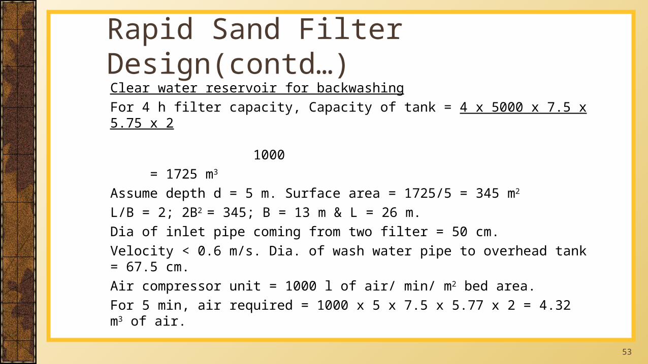
Clear water reservoir for backwashingFor 4 h filter capacity, Capacity of tank = 4 x 5000 x 7.5 x 5.75 x 2 1000
= 1725 m3
Assume depth d = 5 m. Surface area = 1725/5 = 345 m2
L/B = 2; 2B2 = 345; B = 13 m & L = 26 m.Dia of inlet pipe coming from two filter = 50 cm.Velocity < 0.6 m/s. Dia. of wash water pipe to overhead tank = 67.5 cm.Air compressor unit = 1000 l of air/ min/ m2 bed area.For 5 min, air required = 1000 x 5 x 7.5 x 5.77 x 2 = 4.32 m3 of air.
Rapid Sand Filter Design(contd…)
54
Water supply engineering by S.K.Garg,1977Picture Courtesy: http://www.google.comwww.historyofwaterfilterrs.com/filteration
References

55
Recommended