53-1003898-0118 December 2015
Brocade ICX 7250 SwitchHardware Installation Guide
Supporting FastIron Software Release 8.0.40

© 2015, Brocade Communications Systems, Inc. All Rights Reserved.
ADX, Brocade, Brocade Assurance, the B-wing symbol, DCX, Fabric OS, HyperEdge, ICX, MLX, MyBrocade, OpenScript, The EffortlessNetwork, VCS, VDX, Vplane, and Vyatta are registered trademarks, and Fabric Vision and vADX are trademarks of BrocadeCommunications Systems, Inc., in the United States and/or in other countries. Other brands, products, or service names mentioned may betrademarks of others.
Notice: This document is for informational purposes only and does not set forth any warranty, expressed or implied, concerning anyequipment, equipment feature, or service offered or to be offered by Brocade. Brocade reserves the right to make changes to this documentat any time, without notice, and assumes no responsibility for its use. This informational document describes features that may not becurrently available. Contact a Brocade sales office for information on feature and product availability. Export of technical data contained inthis document may require an export license from the United States government.
The authors and Brocade Communications Systems, Inc. assume no liability or responsibility to any person or entity with respect to theaccuracy of this document or any loss, cost, liability, or damages arising from the information contained herein or the computer programs thataccompany it.
The product described by this document may contain open source software covered by the GNU General Public License or other opensource license agreements. To find out which open source software is included in Brocade products, view the licensing terms applicable tothe open source software, and obtain a copy of the programming source code, please visit http://www.brocade.com/support/oscd.
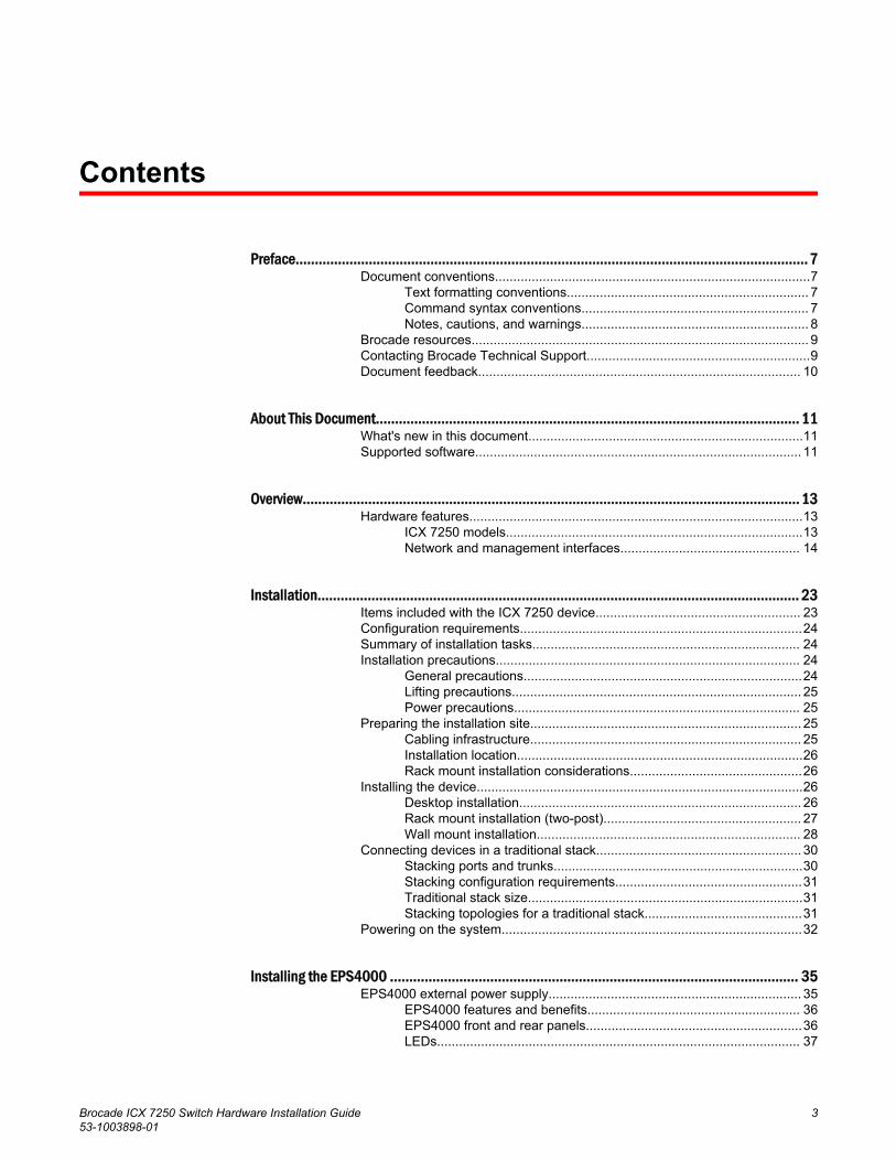
Contents
Preface..................................................................................................................................... 7Document conventions......................................................................................7
Text formatting conventions.................................................................. 7Command syntax conventions.............................................................. 7Notes, cautions, and warnings.............................................................. 8
Brocade resources............................................................................................ 9Contacting Brocade Technical Support.............................................................9Document feedback........................................................................................ 10
About This Document.............................................................................................................. 11What's new in this document...........................................................................11Supported software......................................................................................... 11
Overview................................................................................................................................. 13Hardware features...........................................................................................13
ICX 7250 models.................................................................................13Network and management interfaces................................................. 14
Installation............................................................................................................................. 23Items included with the ICX 7250 device........................................................ 23Configuration requirements.............................................................................24Summary of installation tasks......................................................................... 24Installation precautions................................................................................... 24
General precautions............................................................................24Lifting precautions............................................................................... 25Power precautions.............................................................................. 25
Preparing the installation site.......................................................................... 25Cabling infrastructure.......................................................................... 25Installation location..............................................................................26Rack mount installation considerations...............................................26
Installing the device.........................................................................................26Desktop installation............................................................................. 26Rack mount installation (two-post)...................................................... 27Wall mount installation........................................................................ 28
Connecting devices in a traditional stack........................................................ 30Stacking ports and trunks....................................................................30Stacking configuration requirements...................................................31Traditional stack size...........................................................................31Stacking topologies for a traditional stack...........................................31
Powering on the system..................................................................................32
Installing the EPS4000 .......................................................................................................... 35EPS4000 external power supply..................................................................... 35
EPS4000 features and benefits.......................................................... 36EPS4000 front and rear panels...........................................................36LEDs................................................................................................... 37
Brocade ICX 7250 Switch Hardware Installation Guide 353-1003898-01

Items included with the EPS4000................................................................. 39Configuration requirements...........................................................................39Summary of installation tasks....................................................................... 39Installation precautions................................................................................. 40
General precautions..........................................................................40Lifting precautions.............................................................................40Power precautions............................................................................ 41
Preparing the installation site........................................................................41Rack-mount installation considerations.............................................41
Installing the device.......................................................................................42Desktop installation...........................................................................42Mounting an external power supply in a rack (two-post)...................43
Installing an RPS17 PSU.............................................................................. 45Uninstalling an RPS17 PSU..........................................................................46Connecting the EPS4000 cord......................................................................46Powering on the system................................................................................49
Connecting devices to the external power supply.............................49Verifying proper operation.............................................................................49EPS4000 external power supply technical specifications............................. 50
Configuring the Device.......................................................................................................... 53Configuration tasks....................................................................................... 53PC or terminal attachment............................................................................ 54Password assignment...................................................................................54
Assigning passwords........................................................................ 55Recovering from a lost password......................................................56
IP address configuration............................................................................... 56Devices running Layer 2 software.....................................................56Devices running Layer 3 software.....................................................57
Connecting network devices......................................................................... 59Connectors........................................................................................60Cable specifications.......................................................................... 60Connecting to Ethernet or Fast Ethernet hubs..................................60Connecting to workstations, servers, or routers................................61Connecting a network device to a fiber port......................................61
Troubleshooting network connections.......................................................... 62Digital optical monitoring...................................................................62
Testing connectivity.......................................................................................62Pinging an IP address.......................................................................62Observing LEDs................................................................................63Tracing a route..................................................................................64
Managing an ICX 7250 Device.............................................................................................. 65Managing temperature settings.................................................................... 65
Temperature threshold levels............................................................65Fan detection and error checking policies........................................ 66Shutdown reset time and syslog message....................................... 67Displaying the temperature............................................................... 67Displaying syslog messages for temperature................................... 68Changing the temperature warning level ......................................... 68Changing the temperature poll time..................................................68
Displaying CPU usage.................................................................................. 69Removing MAC address entries................................................................... 69
Hardware Maintenance Schedule..........................................................................................71
4 Brocade ICX 7250 Switch Hardware Installation Guide53-1003898-01

Pre-connection cleaning recommendations.................................................... 71Copper or fiber-optic module replacement......................................................71
Removing a copper or fiber-optic module........................................... 71Installing a fiber-optic transceiver........................................................72Cabling a fiber-optic transceiver..........................................................73Cleaning the fiber-optic connectors.....................................................74
Cabling a fiber-optic transceiver......................................................................74
Brocade ICX 7250 Switch Technical Specifications..................................................................75
Troubleshooting ..................................................................................................................... 87Diagnosing switch indicators...........................................................................87
Installation........................................................................................... 87Power and cooling problems...............................................................87In-band access....................................................................................88
Regulatory Statements............................................................................................................89CE Statement..................................................................................................89China ROHS................................................................................................... 89BSMI statement (Taiwan)................................................................................89Canadian requirements...................................................................................90China CC statement........................................................................................91Europe and Australia (CISPR 22 Class A Warning)....................................... 91FCC warning (US only)................................................................................... 92Germany......................................................................................................... 92KCC statement (Republic of Korea)................................................................92VCCI statement...............................................................................................92
Cautions and Danger Notices.................................................................................................. 93Cautions.......................................................................................................... 93Danger Notices............................................................................................... 96
Brocade ICX 7250 Switch Hardware Installation Guide 553-1003898-01

6 Brocade ICX 7250 Switch Hardware Installation Guide53-1003898-01
Preface
● Document conventions......................................................................................................7● Brocade resources............................................................................................................ 9● Contacting Brocade Technical Support.............................................................................9● Document feedback........................................................................................................ 10
Document conventionsThe document conventions describe text formatting conventions, command syntax conventions, andimportant notice formats used in Brocade technical documentation.
Text formatting conventionsText formatting conventions such as boldface, italic, or Courier font may be used in the flow of the textto highlight specific words or phrases.
Format Description
bold text Identifies command names
Identifies keywords and operands
Identifies the names of user-manipulated GUI elements
Identifies text to enter at the GUI
italic text Identifies emphasis
Identifies variables
Identifies document titles
Courier font Identifies CLI output
Identifies command syntax examples
Command syntax conventionsBold and italic text identify command syntax components. Delimiters and operators define groupings ofparameters and their logical relationships.
Convention Description
bold text Identifies command names, keywords, and command options.
italic text Identifies a variable.
value In Fibre Channel products, a fixed value provided as input to a commandoption is printed in plain text, for example, --show WWN.
Brocade ICX 7250 Switch Hardware Installation Guide 753-1003898-01
Convention Description
[ ] Syntax components displayed within square brackets are optional.
Default responses to system prompts are enclosed in square brackets.
{ x | y | z } A choice of required parameters is enclosed in curly brackets separated byvertical bars. You must select one of the options.
In Fibre Channel products, square brackets may be used instead for thispurpose.
x | y A vertical bar separates mutually exclusive elements.
< > Nonprinting characters, for example, passwords, are enclosed in anglebrackets.
... Repeat the previous element, for example, member[member...].
\ Indicates a “soft” line break in command examples. If a backslash separatestwo lines of a command input, enter the entire command at the prompt withoutthe backslash.
Notes, cautions, and warningsNotes, cautions, and warning statements may be used in this document. They are listed in the order ofincreasing severity of potential hazards.
NOTEA Note provides a tip, guidance, or advice, emphasizes important information, or provides a referenceto related information.
ATTENTIONAn Attention statement indicates a stronger note, for example, to alert you when traffic might beinterrupted or the device might reboot.
CAUTIONA Caution statement alerts you to situations that can be potentially hazardous to you or causedamage to hardware, firmware, software, or data.
DANGERA Danger statement indicates conditions or situations that can be potentially lethal orextremely hazardous to you. Safety labels are also attached directly to products to warn ofthese conditions or situations.
Notes, cautions, and warnings
8 Brocade ICX 7250 Switch Hardware Installation Guide53-1003898-01
Brocade resourcesVisit the Brocade website to locate related documentation for your product and additional Brocaderesources.
You can download additional publications supporting your product at www.brocade.com. Select theBrocade Products tab to locate your product, then click the Brocade product name or image to open theindividual product page. The user manuals are available in the resources module at the bottom of thepage under the Documentation category.
To get up-to-the-minute information on Brocade products and resources, go to MyBrocade. You canregister at no cost to obtain a user ID and password.
Release notes are available on MyBrocade under Product Downloads.
White papers, online demonstrations, and data sheets are available through the Brocade website.
Contacting Brocade Technical SupportAs a Brocade customer, you can contact Brocade Technical Support 24x7 online, by telephone, or by e-mail. Brocade OEM customers contact their OEM/Solutions provider.
Brocade customersFor product support information and the latest information on contacting the Technical AssistanceCenter, go to http://www.brocade.com/services-support/index.html.
If you have purchased Brocade product support directly from Brocade, use one of the following methodsto contact the Brocade Technical Assistance Center 24x7.
Online Telephone E-mail
Preferred method of contact for non-urgent issues:
• My Cases through MyBrocade• Software downloads and licensing
tools• Knowledge Base
Required for Sev 1-Critical and Sev2-High issues:
• Continental US: 1-800-752-8061• Europe, Middle East, Africa, and
Asia Pacific: +800-AT FIBREE(+800 28 34 27 33)
• For areas unable to access tollfree number: +1-408-333-6061
• Toll-free numbers are available inmany countries.
Please include:
• Problem summary• Serial number• Installation details• Environment description
Brocade OEM customersIf you have purchased Brocade product support from a Brocade OEM/Solution Provider, contact yourOEM/Solution Provider for all of your product support needs.
• OEM/Solution Providers are trained and certified by Brocade to support Brocade® products.• Brocade provides backline support for issues that cannot be resolved by the OEM/Solution Provider.
Brocade resources
Brocade ICX 7250 Switch Hardware Installation Guide 953-1003898-01

• Brocade Supplemental Support augments your existing OEM support contract, providing directaccess to Brocade expertise. For more information, contact Brocade or your OEM.
• For questions regarding service levels and response times, contact your OEM/Solution Provider.
Document feedbackTo send feedback and report errors in the documentation you can use the feedback form posted withthe document or you can e-mail the documentation team.
Quality is our first concern at Brocade and we have made every effort to ensure the accuracy andcompleteness of this document. However, if you find an error or an omission, or you think that a topicneeds further development, we want to hear from you. You can provide feedback in two ways:
• Through the online feedback form in the HTML documents posted on www.brocade.com.• By sending your feedback to [email protected].
Provide the publication title, part number, and as much detail as possible, including the topic headingand page number if applicable, as well as your suggestions for improvement.
Document feedback
10 Brocade ICX 7250 Switch Hardware Installation Guide53-1003898-01
About This Document
● What's new in this document...........................................................................................11● Supported software......................................................................................................... 11
What's new in this documentThis document has the following changes:
The thermal policy information (when the fans operate at a low speed, a high speed, and when theswitch shuts off completely due to overheating) has been updated with new temperature numbers in Temperature threshold levels on page 65.
Supported softwareThis document is specific to the Brocade ICX 7450 running FastIron release 08.0.40.
Brocade ICX 7250 Switch Hardware Installation Guide 1153-1003898-01

Supported software
12 Brocade ICX 7250 Switch Hardware Installation Guide53-1003898-01
Overview
● Hardware features...........................................................................................................13
Hardware featuresThe following sections describe the physical characteristics of the devices.
ICX 7250 modelsThe Brocade ICX 7250 Ethernet switch is available in the models listed in the following table.
ICX 7250 modelsTABLE 1
Model Description
Brocade ICX 7250-24G 24 fixed 10/100/1000Base-T, non-PoE ports, 4 SFP 1-GbE uplink ports, no stacking, noEPS4000 connection
Brocade ICX 7250-24 24 fixed 10/100/1000Base-T, non-PoE ports, 8 SFP+ 1-GbE or 10-GbE uplink orstacking ports, EPS4000 connection
Brocade ICX 7250-24P 24 fixed 10/100/1000Base-T, PoE/PoE+ ports, 8 SFP+ 1-GbE or 10-GbE uplink orstacking ports, EPS4000 connection
Brocade ICX 7250-48 48 fixed 10/100/1000Base-T, non-PoE ports, 8 SFP+ 1-GbE or 10-GbE uplink orstacking ports, EPS4000 connection
Brocade ICX 7250-48P 48 fixed 10/100/1000Base-T, PoE/PoE+ ports, 8 SFP+ 1-GbE or 10-GbE uplink orstacking ports, EPS4000 connection
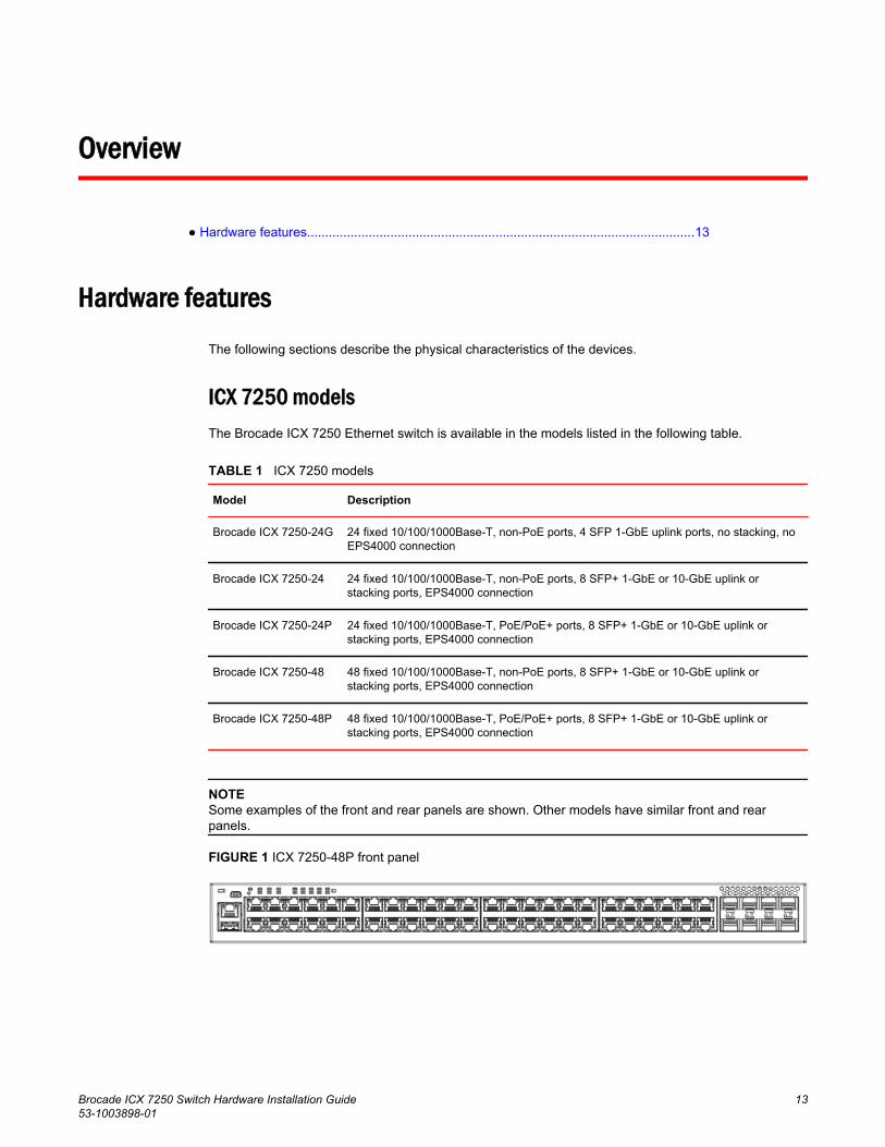
NOTESome examples of the front and rear panels are shown. Other models have similar front and rearpanels.
FIGURE 1 ICX 7250-48P front panel
Brocade ICX 7250 Switch Hardware Installation Guide 1353-1003898-01
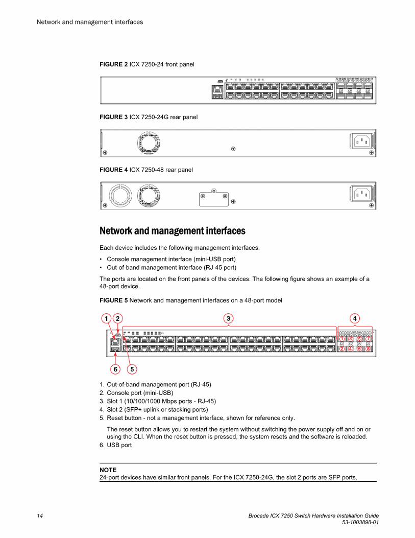
FIGURE 2 ICX 7250-24 front panel
FIGURE 3 ICX 7250-24G rear panel
FIGURE 4 ICX 7250-48 rear panel
Network and management interfacesEach device includes the following management interfaces.
• Console management interface (mini-USB port)• Out-of-band management interface (RJ-45 port)
The ports are located on the front panels of the devices. The following figure shows an example of a48-port device.
FIGURE 5 Network and management interfaces on a 48-port model
1. Out-of-band management port (RJ-45)2. Console port (mini-USB)3. Slot 1 (10/100/1000 Mbps ports - RJ-45)4. Slot 2 (SFP+ uplink or stacking ports)5. Reset button - not a management interface, shown for reference only.
The reset button allows you to restart the system without switching the power supply off and on orusing the CLI. When the reset button is pressed, the system resets and the software is reloaded.
6. USB port
NOTE24-port devices have similar front panels. For the ICX 7250-24G, the slot 2 ports are SFP ports.
Network and management interfaces
14 Brocade ICX 7250 Switch Hardware Installation Guide53-1003898-01
Console management interface
The console management interface is a mini-USB port that allows you to configure and manage thedevice using a third-party terminal emulation application from a directly connected PC or through aterminal server.
Out-of-band management interface
The out-of-band management interface is an RJ-45 port that allows you to access, configure andmanage the device from the network.
Network interfaces for devices
The Brocade ICX 7250 contains the following network interfaces:
• 10/100/1000 Mbps ports with RJ-45 copper connectors• SFP or SFP+ ports
SFP ports support 1 Gbps port speed. SFP+ ports support both 1 Gbps and 10 Gbps port speeds.
NOTERefer to the Brocade ICX 7250 Switch Technical Specifications on page 75 to see the ports supportedby your model.
Slot designations
Refer to Network and management interfaces on page 14 for the location of slot 1 and slot 2 on thefront panel of the 24-port models and the 48-port models.
Slot designations for ICX 7250 devices TABLE 2
Device Slot 1 (10/100/1000 BASE-T ports) Slot 2 (SFP and SFP+ ports)
Brocade ICX 7250-24G RJ-45 ports 1-24 SFP ports 1-4
Brocade ICX 7250-24 RJ-45 ports 1-24 SFP+ ports 1-8
Brocade ICX 7250-24P RJ-45, PoE/PoE+ ports 1-24 SFP+ ports 1-8
Brocade ICX 7250-48 RJ-45 ports 1-48 SFP+ ports 1-8
Brocade ICX 7250-48P RJ-45, PoE/PoE+ ports 1-48 SFP+ ports 1-8
10/100/1000 BASE-T ports
All devices provide 24 or 48 RJ-45 ports that operate at 10 Mbps or 100 Mbps half or full duplex, or at1000 Mbps full duplex. Because all ports support automatic MDI or MDI-X operation, you can usestraight-through cables for all network connections to PCs, servers, or other devices or hubs. Inaddition, it is ideal (and preferred) to use straight-through cables for switch-to-switch connections.
Each port supports auto-negotiation, so the optimum transmission mode (half or full duplex), and thedata rate (10, 100, or 1000 Mbps) can be selected automatically. If a device connected to one of these
Console management interface
Brocade ICX 7250 Switch Hardware Installation Guide 1553-1003898-01
ports does not support auto-negotiation, the communication mode of the port can be configuredmanually.
SFP or SFP+ fiber ports
The Brocade ICX 7250-24G contains four small form-factor pluggable (SFP) ports (ports 1 through 4).The top row contains odd-numbered ports and the bottom row contains even-numbered ports. Theseports reside on slot 2 of the switch and can be used as uplink (data) ports. These ports support 1 Gbpsbut not 10 Gbps port speeds.
All other Brocade ICX 7250 devices contain eight SFP+ ports that support 1 Gbps or 10 Gbps portspeeds. The top row ports are odd numbered (ports 1, 3, 5, and 7) and the bottom row ports are evennumbered (ports 2, 4, 6, and 8). All ports can be used for stacking or uplinking.
NOTEYou may need software licenses to enable some SFP+ ports at the full 10 Gbps. Refer to the FastIronEthernet Switch Software Licensing Guide for more information.
For information about supported SFP and SFP+ transceivers, refer to the Brocade datasheet.
Specifying a port address
You can specify a port address for an uplink (data) port, a stacking port, or a management port.
Specifying a data port
The port address format is stack-unit/slot/port:
• stack-unit: Specifies the stack unit ID. The range is from 1 through the maximum number of devicessupported in a stack. Refer to the technical specifications for your device for the actual value. If thedevice is not part of a stack, the stack unit ID is 1.
• slot: Specifies the slot number; either 1 or 2.• port: Specifies the port number in the slot. The range is from 1 through 24 (24-port models) or 1
through 48 (48-port models) for the RJ-45 ports. For the SFP ports, the range is from 1 through 4,and for the SFP+ ports, the range is from 1 through 8.
The following example shows how to specify port 2 in slot 1 of a device that is not part of a stack:
device (config)# interface ethernet 1/1/2
Specifying a stacking port
The port address format is stack-unit/slot/port:
• stack-unit: Specifies the stack unit ID. For models that support stacking, the range is from 1 throughthe maximum number of devices (units) that can be supported in the stack.
• slot: Specifies the slot number. Stacking ports are in slot 2.• port: Specifies the port number in the slot.
The following example shows how to specify stacking port 3 in slot 2 of unit 3 in a stack:
device (config)# interface ethernet 3/2/3
SFP or SFP+ fiber ports
16 Brocade ICX 7250 Switch Hardware Installation Guide53-1003898-01
Specifying a management port
The management port number is always 1. This example shows how to specify the management port:
device (config)# interface management 1
Port, system, and power status LEDs
The devices include LEDs that indicate the status of device components.
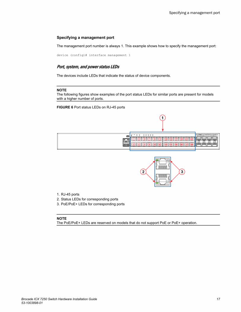
NOTEThe following figures show examples of the port status LEDs for similar ports are present for modelswith a higher number of ports.
FIGURE 6 Port status LEDs on RJ-45 ports
1. RJ-45 ports2. Status LEDs for corresponding ports3. PoE/PoE+ LEDs for corresponding ports
NOTEThe PoE/PoE+ LEDs are reserved on models that do not support PoE or PoE+ operation.
Specifying a management port
Brocade ICX 7250 Switch Hardware Installation Guide 1753-1003898-01
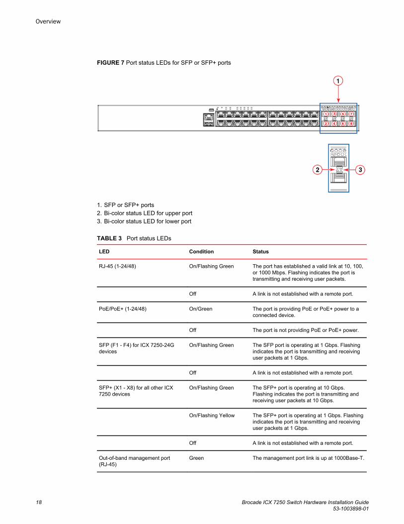
FIGURE 7 Port status LEDs for SFP or SFP+ ports
1. SFP or SFP+ ports2. Bi-color status LED for upper port3. Bi-color status LED for lower port
Port status LEDsTABLE 3
LED Condition Status
RJ-45 (1-24/48) On/Flashing Green The port has established a valid link at 10, 100,or 1000 Mbps. Flashing indicates the port istransmitting and receiving user packets.
Off A link is not established with a remote port.
PoE/PoE+ (1-24/48) On/Green The port is providing PoE or PoE+ power to aconnected device.
Off The port is not providing PoE or PoE+ power.
SFP (F1 - F4) for ICX 7250-24Gdevices
On/Flashing Green The SFP port is operating at 1 Gbps. Flashingindicates the port is transmitting and receivinguser packets at 1 Gbps.
Off A link is not established with a remote port.
SFP+ (X1 - X8) for all other ICX7250 devices
On/Flashing Green The SFP+ port is operating at 10 Gbps.Flashing indicates the port is transmitting andreceiving user packets at 10 Gbps.
On/Flashing Yellow The SFP+ port is operating at 1 Gbps. Flashingindicates the port is transmitting and receivinguser packets at 1 Gbps.
Off A link is not established with a remote port.
Out-of-band management port(RJ-45)
Green The management port link is up at 1000Base-T.
Overview
18 Brocade ICX 7250 Switch Hardware Installation Guide53-1003898-01
Port status LEDs (Continued)TABLE 3
LED Condition Status
Off Either the management port link is up at100Base-Tx/10Base-T, or the link is down.
Blinking green The port is receiving and transmitting data.
Off No data is being received or transmitted.
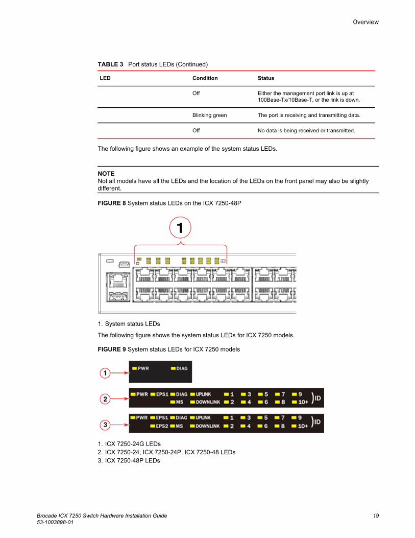
The following figure shows an example of the system status LEDs.
NOTENot all models have all the LEDs and the location of the LEDs on the front panel may also be slightlydifferent.
FIGURE 8 System status LEDs on the ICX 7250-48P
1. System status LEDs
The following figure shows the system status LEDs for ICX 7250 models.
FIGURE 9 System status LEDs for ICX 7250 models
1. ICX 7250-24G LEDs2. ICX 7250-24, ICX 7250-24P, ICX 7250-48 LEDs3. ICX 7250-48P LEDs
Overview
Brocade ICX 7250 Switch Hardware Installation Guide 1953-1003898-01
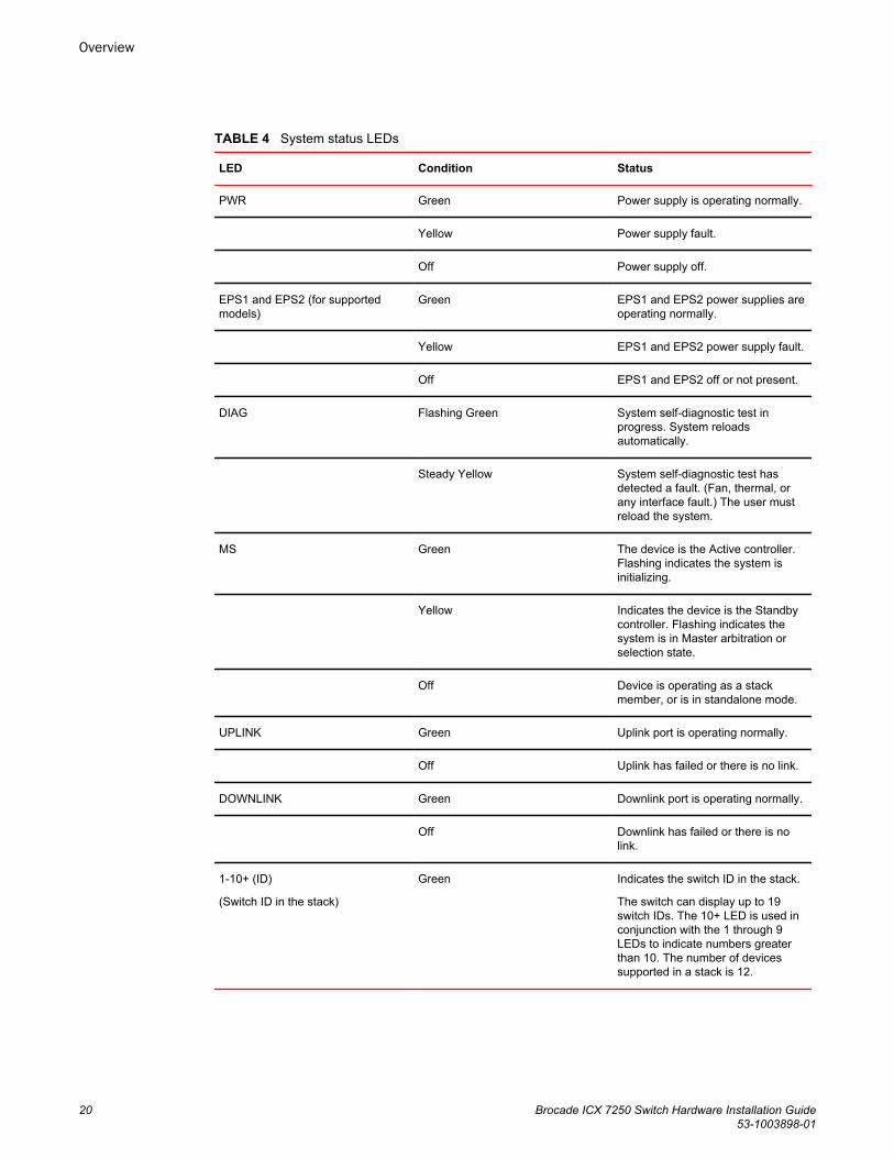
System status LEDsTABLE 4
LED Condition Status
PWR Green Power supply is operating normally.
Yellow Power supply fault.
Off Power supply off.
EPS1 and EPS2 (for supportedmodels)
Green EPS1 and EPS2 power supplies areoperating normally.
Yellow EPS1 and EPS2 power supply fault.
Off EPS1 and EPS2 off or not present.
DIAG Flashing Green System self-diagnostic test inprogress. System reloadsautomatically.
Steady Yellow System self-diagnostic test hasdetected a fault. (Fan, thermal, orany interface fault.) The user mustreload the system.
MS Green The device is the Active controller.Flashing indicates the system isinitializing.
Yellow Indicates the device is the Standbycontroller. Flashing indicates thesystem is in Master arbitration orselection state.
Off Device is operating as a stackmember, or is in standalone mode.
UPLINK Green Uplink port is operating normally.
Off Uplink has failed or there is no link.
DOWNLINK Green Downlink port is operating normally.
Off Downlink has failed or there is nolink.
1-10+ (ID)
(Switch ID in the stack)
Green Indicates the switch ID in the stack.
The switch can display up to 19switch IDs. The 10+ LED is used inconjunction with the 1 through 9LEDs to indicate numbers greaterthan 10. The number of devicessupported in a stack is 12.
Overview
20 Brocade ICX 7250 Switch Hardware Installation Guide53-1003898-01
Power supplies
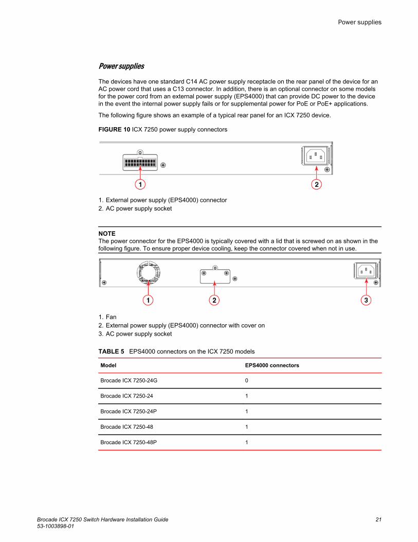
The devices have one standard C14 AC power supply receptacle on the rear panel of the device for anAC power cord that uses a C13 connector. In addition, there is an optional connector on some modelsfor the power cord from an external power supply (EPS4000) that can provide DC power to the devicein the event the internal power supply fails or for supplemental power for PoE or PoE+ applications.
The following figure shows an example of a typical rear panel for an ICX 7250 device.
FIGURE 10 ICX 7250 power supply connectors
1. External power supply (EPS4000) connector2. AC power supply socket
NOTEThe power connector for the EPS4000 is typically covered with a lid that is screwed on as shown in thefollowing figure. To ensure proper device cooling, keep the connector covered when not in use.
1. Fan2. External power supply (EPS4000) connector with cover on3. AC power supply socket
EPS4000 connectors on the ICX 7250 modelsTABLE 5
Model EPS4000 connectors
Brocade ICX 7250-24G 0
Brocade ICX 7250-24 1
Brocade ICX 7250-24P 1
Brocade ICX 7250-48 1
Brocade ICX 7250-48P 1
Power supplies
Brocade ICX 7250 Switch Hardware Installation Guide 2153-1003898-01
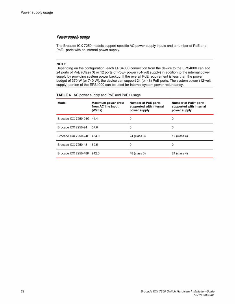
Power supply usage
The Brocade ICX 7250 models support specific AC power supply inputs and a number of PoE andPoE+ ports with an internal power supply.
NOTEDepending on the configuration, each EPS4000 connection from the device to the EPS4000 can add24 ports of PoE (Class 3) or 12 ports of PoE+ power (54-volt supply) in addition to the internal powersupply by providing system power backup. If the overall PoE requirement is less than the powerbudget of 370 W (or 740 W), the device can support 24 (or 48) PoE ports. The system power (12-voltsupply) portion of the EPS4000 can be used for internal system power redundancy.
AC power supply and PoE and PoE+ usageTABLE 6
Model Maximum power drawfrom AC line input(Watts)
Number of PoE portssupported with internalpower supply
Number of PoE+ portssupported with internalpower supply
Brocade ICX 7250-24G 44.4 0 0
Brocade ICX 7250-24 57.6 0 0
Brocade ICX 7250-24P 454.0 24 (class 3) 12 (class 4)
Brocade ICX 7250-48 69.5 0 0
Brocade ICX 7250-48P 942.0 48 (class 3) 24 (class 4)
Power supply usage
22 Brocade ICX 7250 Switch Hardware Installation Guide53-1003898-01
Installation
● Items included with the ICX 7250 device........................................................................ 23● Configuration requirements.............................................................................................24● Summary of installation tasks......................................................................................... 24● Installation precautions................................................................................................... 24● Preparing the installation site.......................................................................................... 25● Installing the device.........................................................................................................26● Connecting devices in a traditional stack........................................................................ 30● Powering on the system..................................................................................................32
DANGERThe procedures in this manual are for qualified service personnel.
DANGERBefore beginning the installation, see the precautions in “Power precautions.”
CAUTIONDisassembling any part of the power supply and fan assembly voids the warranty and regulatorycertifications. There are no user-serviceable parts inside the power supply and fan assembly.
Items included with the ICX 7250 deviceICX 7250 devices ship with all of the following items included in your shipping container. Verify thecontents of your shipping container. If any items are missing, contact the place of purchase.
• ICX 7250 device• Rack mounting kit containing two L-shaped mounting brackets and two sets of eight sink-head
screws• Wall mounting kit containing two wall-mount screws and two plastic anchors• Two-post rack kit containing four rack-mounting screws and four cage nuts• One AC power cord (US only)• Power cord retainer clip• Console cable• DB9 adapter• Four rubber feet• China ROHS sheet• Read Me First document
Brocade ICX 7250 Switch Hardware Installation Guide 2353-1003898-01
Configuration requirementsTo manage the ICX 7250, you need a management station, such as a PC running a terminalemulation application, for serial connection to the device.
Use the serial connection to perform basic configuration tasks, including assigning an IP address andnetwork mask to the system. This information is required to manage the system using the CLI throughTelnet or Brocade Network Advisor.
Summary of installation tasksFollow the steps in the following table to install your device. Details for each of these steps areprovided on the pages indicated.
Installation tasks TABLE 7
Task number Task Where to find more information
1 Ensure that the physical environment that will host thedevice has the proper cabling and ventilation.
Preparing the installation site on page25
2 Unpack the device and all included accessories. Items included with the ICX 7250 deviceon page 23
3 Install the device on a desktop, or in an equipmentrack.
Installing the device on page 26
4 Once the device is installed, plug the device into anearby power source that adheres to the regulatoryrequirements outlined in this manual.
Powering on the system on page 32
Installation precautionsFollow all precautions when installing a device.
General precautions
DANGERAll fiber-optic interfaces use Class 1 lasers.
CAUTIONDo not install the device in an environment where the operating ambient temperature mightexceed 50°C (122°F).
Configuration requirements
24 Brocade ICX 7250 Switch Hardware Installation Guide53-1003898-01
CAUTIONMake sure the airflow around the front, sides, and back of the device is not restricted.
Lifting precautions
DANGERMake sure the rack housing the device is adequately secured to prevent it from becomingunstable or falling over.
DANGERMount the devices you install in a rack as low as possible. Place the heaviest device at thebottom and progressively place lighter devices above.
Power precautions
CAUTIONUse a separate branch circuit for each power cord, which provides redundancy in case one ofthe circuits fails.
CAUTIONEnsure that the device does not overload the power circuits, wiring, and over-current protection.To determine the possibility of overloading the supply circuits, add the ampere (amp) ratings ofall devices installed on the same circuit as the device. Compare this total with the rating limit forthe circuit. The maximum ampere ratings are usually printed on the devices near the inputpower connectors.
DANGERDisconnect the power cord from all power sources to completely remove power from the device.
DANGERIf the installation requires a different power cord than the one supplied with the device, makesure you use a power cord displaying the mark of the safety agency that defines the regulationsfor power cords in your country. The mark is your assurance that the power cord can be usedsafely with the device.
Preparing the installation siteBefore installing the device, plan its location and orientation relative to other devices and equipment.
Cabling infrastructureEnsure that the proper cabling is installed at the site. For information about supported SFP and SFP+transceivers and cable lengths and types, refer to the Brocade optics family datasheet.
Lifting precautions
Brocade ICX 7250 Switch Hardware Installation Guide 2553-1003898-01
Installation locationDevices can be mounted in a standard 19-inch equipment rack, on the wall, or on a flat surface.
The site should meet the following requirements:
• Maintain the operating environment as specified in the Technical Specifications.• Allow a minimum of 7.62 cm (3 in.) of space between the front and the back of the device and walls
or other obstructions for proper airflow.• Allow at least 7.62 cm (3 in.) of space at the front and back of the device for the twisted-pair, fiber-
optic, and power cabling.• The site should be accessible for installing, cabling, and maintaining the devices.• Allow the status LEDs to be clearly visible.• Allow for twisted-pair cables to be routed away from power lines, fluorescent lighting fixtures, and
other sources of electrical interference, such as radios and transmitters.• Allow for the unit to be connected to a separate grounded power outlet that provides 100 to 240
VAC, 50 to 60 Hz, within 2 m (6.6 ft) of each device, and is powered from an independent circuitbreaker. As with any equipment, a filter or surge suppressor is recommended.
• Some combinations of intake and exhaust airflows may not be compatible with your environment.
Rack mount installation considerationsBefore mounting the device in a rack, ensure that the following rack mount installation requirementsare met:
• Temperature: Because the temperature within a rack assembly may be higher than the ambientroom temperature, check that the rack-environment temperature is within the specified operatingtemperature range. Refer to Brocade ICX 7250 Switch Technical Specifications on page 75.
• Airflow: Be sure that the airflow direction for all equipment in a rack is the same or consistent.• Mechanical loading: Do not place any equipment on top of a rack-mounted unit.• Circuit overloading: Be sure that the supply circuit to the rack assembly is not overloaded.• Grounding: Rack-mounted equipment should be properly grounded.
Installing the deviceYou can install the device on a desktop, the wall, or in an equipment rack.
DANGERMount the devices you install in a rack as low as possible. Place the heaviest device at thebottom and progressively place lighter devices above.
Desktop installationComplete the following steps to install the ICX 7250 device on a desktop or other flat surface. Thedevice you are installing might look different than the one in the following illustration.
DANGERThis equipment is suitable for mounting on concrete or other noncombustible surfaces only.
Installation location
26 Brocade ICX 7250 Switch Hardware Installation Guide53-1003898-01
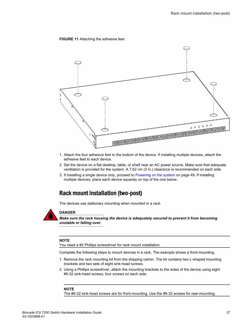
FIGURE 11 Attaching the adhesive feet
1. Attach the four adhesive feet to the bottom of the device. If installing multiple devices, attach theadhesive feet to each device.
2. Set the device on a flat desktop, table, or shelf near an AC power source. Make sure that adequateventilation is provided for the system. A 7.62 cm (3 in.) clearance is recommended on each side.
3. If installing a single device only, proceed to Powering on the system on page 49. If installingmultiple devices, place each device squarely on top of the one below.
Rack mount installation (two-post)The devices use stationary mounting when mounted in a rack.
DANGERMake sure the rack housing the device is adequately secured to prevent it from becomingunstable or falling over.
NOTEYou need a #2 Phillips screwdriver for rack mount installation.
Complete the following steps to mount devices in a rack. The example shows a front-mounting.
1. Remove the rack mounting kit from the shipping carton. The kit contains two L-shaped mountingbrackets and two sets of eight sink-head screws.
2. Using a Phillips screwdriver, attach the mounting brackets to the sides of the device using eight#6-32 sink-head screws, four screws on each side.
NOTEThe #6-32 sink-head screws are for front-mounting. Use the #8-32 screws for rear-mounting.
Rack mount installation (two-post)
Brocade ICX 7250 Switch Hardware Installation Guide 2753-1003898-01
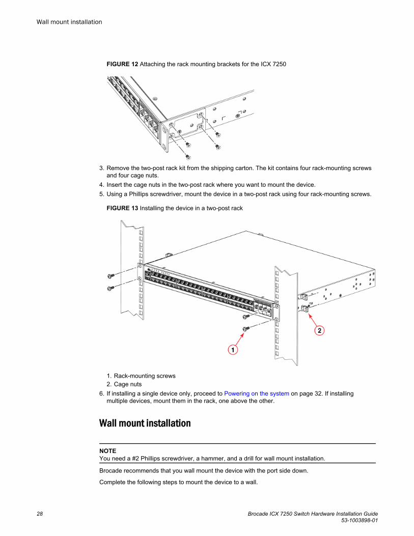
FIGURE 12 Attaching the rack mounting brackets for the ICX 7250
3. Remove the two-post rack kit from the shipping carton. The kit contains four rack-mounting screwsand four cage nuts.
4. Insert the cage nuts in the two-post rack where you want to mount the device.5. Using a Phillips screwdriver, mount the device in a two-post rack using four rack-mounting screws.
FIGURE 13 Installing the device in a two-post rack
1. Rack-mounting screws2. Cage nuts
6. If installing a single device only, proceed to Powering on the system on page 32. If installingmultiple devices, mount them in the rack, one above the other.
Wall mount installation
NOTEYou need a #2 Phillips screwdriver, a hammer, and a drill for wall mount installation.
Brocade recommends that you wall mount the device with the port side down.
Complete the following steps to mount the device to a wall.
Wall mount installation
28 Brocade ICX 7250 Switch Hardware Installation Guide53-1003898-01
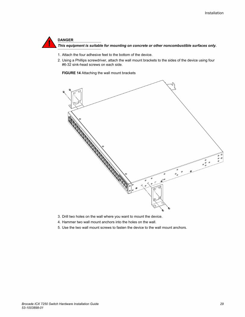
DANGERThis equipment is suitable for mounting on concrete or other noncombustible surfaces only.
1. Attach the four adhesive feet to the bottom of the device.2. Using a Phillips screwdriver, attach the wall mount brackets to the sides of the device using four
#6-32 sink-head screws on each side.
FIGURE 14 Attaching the wall mount brackets
3. Drill two holes on the wall where you want to mount the device.4. Hammer two wall mount anchors into the holes on the wall.5. Use the two wall mount screws to fasten the device to the wall mount anchors.
Installation
Brocade ICX 7250 Switch Hardware Installation Guide 2953-1003898-01
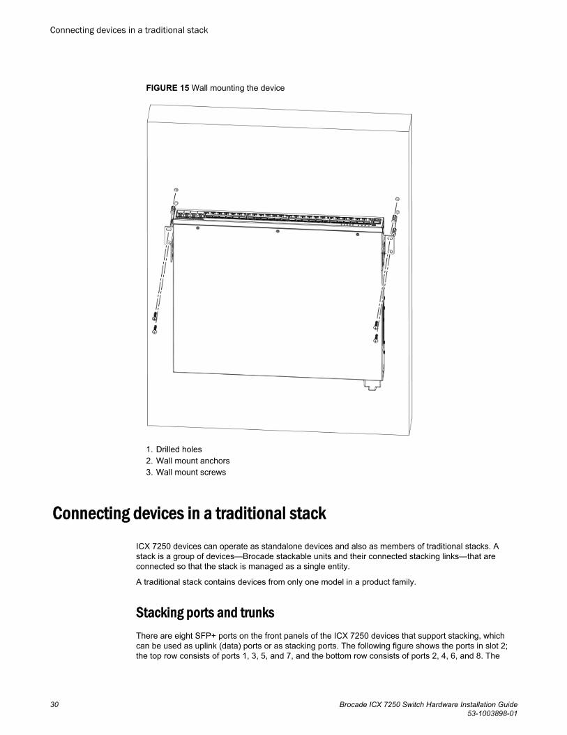
FIGURE 15 Wall mounting the device
1. Drilled holes2. Wall mount anchors3. Wall mount screws
Connecting devices in a traditional stackICX 7250 devices can operate as standalone devices and also as members of traditional stacks. Astack is a group of devices—Brocade stackable units and their connected stacking links—that areconnected so that the stack is managed as a single entity.
A traditional stack contains devices from only one model in a product family.
Stacking ports and trunksThere are eight SFP+ ports on the front panels of the ICX 7250 devices that support stacking, whichcan be used as uplink (data) ports or as stacking ports. The following figure shows the ports in slot 2;the top row consists of ports 1, 3, 5, and 7, and the bottom row consists of ports 2, 4, 6, and 8. The
Connecting devices in a traditional stack
30 Brocade ICX 7250 Switch Hardware Installation Guide53-1003898-01
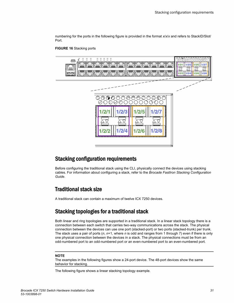
numbering for the ports in the following figure is provided in the format x/x/x and refers to StackID/Slot/Port.
FIGURE 16 Stacking ports
Stacking configuration requirementsBefore configuring the traditional stack using the CLI, physically connect the devices using stackingcables. For information about configuring a stack, refer to the Brocade FastIron Stacking ConfigurationGuide.
Traditional stack sizeA traditional stack can contain a maximum of twelve ICX 7250 devices.
Stacking topologies for a traditional stackBoth linear and ring topologies are supported in a traditional stack. In a linear stack topology there is aconnection between each switch that carries two-way communications across the stack. The physicalconnection between the devices can use one port (stacked-port) or two ports (stacked-trunk) per trunk.The stack uses a pair of ports (n, n+1, where n is odd and ranges from 1 through 7) even if there is onlyone physical connection between the devices in a stack. The physical connections must be from anodd-numbered port to an odd-numbered port or an even-numbered port to an even-numbered port.
NOTEThe examples in the following figures show a 24-port device. The 48-port devices show the samebehavior for stacking.
The following figure shows a linear stacking topology example.
Stacking configuration requirements
Brocade ICX 7250 Switch Hardware Installation Guide 3153-1003898-01
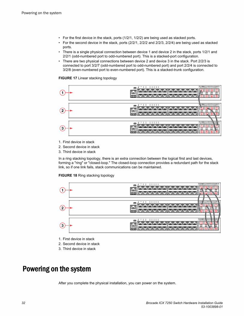
• For the first device in the stack, ports (1/2/1, 1/2/2) are being used as stacked ports.• For the second device in the stack, ports (2/2/1, 2/2/2 and 2/2/3, 2/2/4) are being used as stacked
ports.• There is a single physical connection between device 1 and device 2 in the stack, ports 1/2/1 and
2/2/1 (odd-numbered port to odd-numbered port). This is a stacked-port configuration.• There are two physical connections between device 2 and device 3 in the stack. Port 2/2/3 is
connected to port 3/2/7 (odd-numbered port to odd-numbered port) and port 2/2/4 is connected to3/2/8 (even-numbered port to even-numbered port). This is a stacked-trunk configuration.
FIGURE 17 Linear stacking topology
1. First device in stack2. Second device in stack3. Third device in stack
In a ring stacking topology, there is an extra connection between the logical first and last devices,forming a "ring" or "closed-loop." The closed-loop connection provides a redundant path for the stacklink, so if one link fails, stack communications can be maintained.
FIGURE 18 Ring stacking topology
1. First device in stack2. Second device in stack3. Third device in stack
Powering on the system
After you complete the physical installation, you can power on the system.
Powering on the system
32 Brocade ICX 7250 Switch Hardware Installation Guide53-1003898-01

NOTEThe power outlet should be installed near the equipment and should be easily accessible.
1. Remove the power cord from the shipping container.2. Install the power cord clip.3. Attach the AC power cord to the AC connector on the rear panel.4. Insert the power cord plug into a 100V-240V outlet.
NOTETo turn the system off, simply unplug the power cord or cords.
Installation
Brocade ICX 7250 Switch Hardware Installation Guide 3353-1003898-01

Powering on the system
34 Brocade ICX 7250 Switch Hardware Installation Guide53-1003898-01

Installing the EPS4000
● EPS4000 external power supply..................................................................................... 35● Items included with the EPS4000................................................................................... 39● Configuration requirements.............................................................................................39● Summary of installation tasks......................................................................................... 39● Installation precautions................................................................................................... 40● Preparing the installation site.......................................................................................... 41● Installing the device.........................................................................................................42● Installing an RPS17 PSU................................................................................................ 45● Uninstalling an RPS17 PSU............................................................................................46● Connecting the EPS4000 cord........................................................................................46● Powering on the system..................................................................................................49● Verifying proper operation...............................................................................................49● EPS4000 external power supply technical specifications............................................... 50
DANGERThe procedures in this manual are for qualified service personnel.
DANGERBefore beginning the installation, see the precautions in “Power precautions.”
DANGERBe careful not to accidently insert your fingers into the fan tray while removing it from thechassis. The fan may still be spinning at a high speed.
EPS4000 external power supplyIn the event of an AC power loss or internal power supply device failure, the Brocade EPS4000 externalpower supply can be used as a 12 V, backup power source to a device when any of the DC powersupply ports are connected to an ICX 7250 device. The EPS4000 requires a minimum of one RPS17Power Supply Unit (PSU) to be functional. Proprietary DC cables are used to connect any of the EPSDC ports of the EPS4000 to the rear EPS4000 port of an ICX 7250 device that is supported by theEPS4000. Each RPS17 PSU can provide backup power to one ICX 7250 device. Even though a fullypopulated EPS4000 can monitor up to sixteen connected devices, the EPS4000 can provide backuppower without performance degradation to only four ICX 7250 devices.
NOTEThe primary source of 12 V power for an ICX 7250 device is the internal power supply. The EPS4000 isdesigned to serve primarily as a backup source of 12 V power. You should service a failed ICX 7250device as soon as possible after a 12 V power failure is detected.
In case of a 54 V supply failure, the EPS4000 can provide power to multiple devices up to its capacitylimit. You can set the system priority for the power budget allocation for this scenario. The default is for
Brocade ICX 7250 Switch Hardware Installation Guide 3553-1003898-01

the lower-numbered port to have the higher priority. Should a higher priority device have a 54 V supplyfailure while a lower priority device is already being serviced by the PSU, the power supply will notswitch to provide power to the higher priority device to maintain continuity of service. The EPS4000uses the next PoE-power-budget cycle to reallocate power among the connected ICX 7250 devices.
In the PoE power extension mode, the EPS4000 can also provide additional power to support the PoEports as needed. For more information about connecting an ICX 7250 device to the EPS4000, refer to Connecting devices to the external power supply on page 49.
Each RPS17 PSU can provide up to 740 W at 54 V and 120 W at 12 V. The RPS17 draws power froma standard AC source and converts it to DC for use by the switches.
NOTEThe internal power supply of the ICX 7250 devices is not a field-replaceable unit (FRU). The devicesmust be shut down by administrators for replacement.
Brocade recommends that you pay attention to the PoE or PoE+ port configuration of the device whenconnecting to an EPS4000. The internal power supply of each PoE or PoE+ device has a maximumnumber of supported PoE or PoE+ ports. Brocade recommends that when the EPS4000 is used as aredundant power source for the PoE device, that the maximum number of PoE or PoE+ ports of theexternal power supply must not exceed the maximum number of PoE or PoE+ ports of the internalpower supply capability of each device.
The following devices are supported by the Brocade EPS4000:
• ICX 7250-24• ICX 7250-24P• ICX 7250-48• ICX 7250-48P
NOTEThe ICX 7250-24G is not supported by the EPS4000.
EPS4000 features and benefits• Hosts up to four hot-swappable RPS17 power supply units (PSUs).• Provides N:1 power redundancy at 12 V with each PSU.• Each RPS17 can deliver a maximum of 740 W at 54 V and 120 W at 12 V.• A fully populated EPS4000 has 8 DC power ports that can monitor up to 16 switches simultaneously
and provide 12 V redundant power to four switches.• Provides power redundancy at 54 V and true extended PoE power support.• 1:1 and 1:2 cables support 54 V or 12 V distribution up to 1 meter.• Universal (100-240 V) AC line cord draws power from standard power outlet.• The EPS4000 firmware is field-upgradeable.• The power to the switches is maintained while the microcontroller unit (MCU) is being reset.• The power distribution to the connected switches can be controlled per a priority scheme that you
set.
EPS4000 front and rear panelsThere are 32 LEDs on the front panel of the EPS4000 to indicate the status for the DC power on the 8ports. 16 LEDs (Ex.y) are for the 54 VDC and the other sixteen (Rx.y) are for the 12 VDC supply.There is a reset button next to the LEDs. There are port LEDs for each of the management ports. Both
EPS4000 features and benefits
36 Brocade ICX 7250 Switch Hardware Installation Guide53-1003898-01
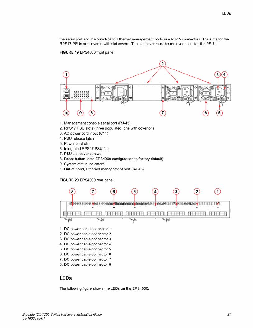
the serial port and the out-of-band Ethernet management ports use RJ-45 connectors. The slots for theRPS17 PSUs are covered with slot covers. The slot cover must be removed to install the PSU.
FIGURE 19 EPS4000 front panel
1. Management console serial port (RJ-45)2. RPS17 PSU slots (three populated, one with cover on)3. AC power cord input (C14)4. PSU release latch5. Power cord clip6. Integrated RPS17 PSU fan7. PSU slot cover screws8. Reset button (sets EPS4000 configuration to factory default)9. System status indicators10.Out-of-band, Ethernet management port (RJ-45)
FIGURE 20 EPS4000 rear panel
1. DC power cable connector 12. DC power cable connector 23. DC power cable connector 34. DC power cable connector 45. DC power cable connector 56. DC power cable connector 67. DC power cable connector 78. DC power cable connector 8
LEDsThe following figure shows the LEDs on the EPS4000.
LEDs
Brocade ICX 7250 Switch Hardware Installation Guide 3753-1003898-01
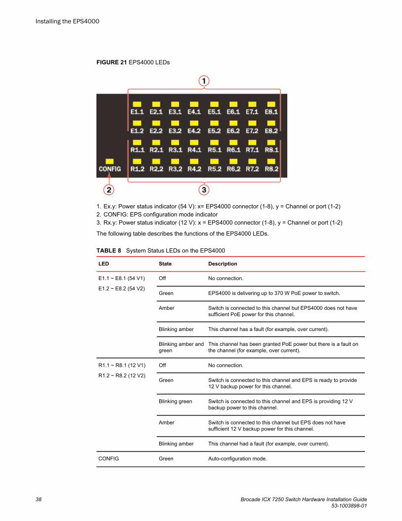
FIGURE 21 EPS4000 LEDs
1. Ex.y: Power status indicator (54 V): x= EPS4000 connector (1-8), y = Channel or port (1-2)2. CONFIG: EPS configuration mode indicator3. Rx.y: Power status indicator (12 V): x = EPS4000 connector (1-8), y = Channel or port (1-2)
The following table describes the functions of the EPS4000 LEDs.
System Status LEDs on the EPS4000TABLE 8
LED State Description
E1.1 ~ E8.1 (54 V1)
E1.2 ~ E8.2 (54 V2)
Off No connection.
Green EPS4000 is delivering up to 370 W PoE power to switch.
Amber Switch is connected to this channel but EPS4000 does not havesufficient PoE power for this channel.
Blinking amber This channel has a fault (for example, over current).
Blinking amber andgreen
This channel has been granted PoE power but there is a fault onthe channel (for example, over current).
R1.1 ~ R8.1 (12 V1)
R1.2 ~ R8.2 (12 V2)
Off No connection.
Green Switch is connected to this channel and EPS is ready to provide12 V backup power for this channel.
Blinking green Switch is connected to this channel and EPS is providing 12 Vbackup power to this channel.
Amber Switch is connected to this channel but EPS does not havesufficient 12 V backup power for this channel.
Blinking amber This channel had a fault (for example, over current).
CONFIG Green Auto-configuration mode.
Installing the EPS4000
38 Brocade ICX 7250 Switch Hardware Installation Guide53-1003898-01
System Status LEDs on the EPS4000 (Continued)TABLE 8
LED State Description
Amber Manual configuration mode.
Management port LED
(Left down)
Green Management port link up at 100BASE-T mode.
Off Management port link up at 10BASE-T mode or link is down.
Management port LED
(Right down)
Blinking green Indicates management port receive and transmit activity.
Off Indicates no Ethernet traffic on management port.
Items included with the EPS4000The EPS4000 ships with all of the following items included in your shipping container. Verify thecontents of your shipping container. If any items are missing, contact the place of purchase.
• EPS4000 external power supply• Rack mounting kit containing two L-shaped mounting brackets and eight sink-head screws• Two-post rack kit containing four rack-mounting screws and four cage nuts• Four rubber feet• Console cable• RJ-45 to DB9 adapter• China ROHS sheet• Read Me First document
Configuration requirementsThe configuration requirements for the EPS4000 are the same as the for the ICX 7250. Refer to Configuration requirements on page 24.
Summary of installation tasksFollow the steps in the following table to install your device. Details for each of these steps are providedon the pages indicated.
Installation tasks TABLE 9
Task number Task Where to find more information
1 Ensure that the physical environment that will host thedevice has the proper cabling and ventilation.
Preparing the installation site on page41 section
Items included with the EPS4000
Brocade ICX 7250 Switch Hardware Installation Guide 3953-1003898-01
Installation tasks (Continued)TABLE 9
Task number Task Where to find more information
2 Unpack the device and all included accessories. Items included with the EPS4000 onpage 39 section
3 Install the device on a desktop, or in an equipment rack. Installing the device on page 42section
4 Once the device is installed, plug the device into a nearbypower source that adheres to the regulatory requirementsoutlined in this manual.
Powering on the system on page 49section
5 Verify that the device is working properly by plugging itinto a power source and verifying that it passes the selftest.
Verifying proper operation on page49 section
Installation precautionsFollow all precautions when installing a device.
General precautions
DANGERAll fiber-optic interfaces use Class 1 lasers.
CAUTIONDo not install the device in an environment where the operating ambient temperature mightexceed 50°C (122°F).
CAUTIONMake sure the airflow around the front, sides, and back of the device is not restricted.
Lifting precautions
DANGERMake sure the rack housing the device is adequately secured to prevent it from becomingunstable or falling over.
DANGERMount the devices you install in a rack as low as possible. Place the heaviest device at thebottom and progressively place lighter devices above.
Installation precautions
40 Brocade ICX 7250 Switch Hardware Installation Guide53-1003898-01
Power precautions
CAUTIONUse a separate branch circuit for each power cord, which provides redundancy in case one ofthe circuits fails.
CAUTIONEnsure that the device does not overload the power circuits, wiring, and over-current protection.To determine the possibility of overloading the supply circuits, add the ampere (amp) ratings ofall devices installed on the same circuit as the device. Compare this total with the rating limit forthe circuit. The maximum ampere ratings are usually printed on the devices near the inputpower connectors.
DANGERDisconnect the power cord from all power sources to completely remove power from the device.
CAUTIONBefore plugging a cable into to any port, be sure to discharge the voltage stored on the cable bytouching the electrical contacts to ground surface.
DANGERIf the installation requires a different power cord than the one supplied with the device, makesure you use a power cord displaying the mark of the safety agency that defines the regulationsfor power cords in your country. The mark is your assurance that the power cord can be usedsafely with the device.
Preparing the installation siteEPS4000 external power supplies can be mounted in a standard 19-inch equipment rack or on a flatsurface.
The installation site should meet these requirements:
• Be at the center of all the devices you want to link, and near a power outlet.• Maintain temperatures within 0 to 50°C (32 to 122°F) and humidity levels within 5 to 95%, non-
condensing.• Provide adequate space (approximately 5.08 cm [2 in.]) on all sides for proper airflow.• Be accessible for installing, cabling, and maintaining the devices.• Allow the status LEDs to be clearly visible.• Allow for twisted-pair cables to be routed away from power lines, fluorescent lighting fixtures, and
other sources of electrical interference, such as radios and transmitters.• Provide a separate grounded power outlet that provides 100 to 240 VAC, 50 - 60 Hz, is within 2.44 m
(8 ft) of each device, and is powered from an independent circuit breaker.• As with any electrical equipment, a filter or surge suppressor is recommended.
Rack-mount installation considerationsBefore mounting the external power supply in a rack, consider the following factors:
Power precautions
Brocade ICX 7250 Switch Hardware Installation Guide 4153-1003898-01
• Temperature: Because the temperature within a rack assembly may be higher than the ambientroom temperature, check that the rack-environment temperature is within the specified operatingtemperature range.
• Airflow: Be sure that the airflow direction for all equipment in a rack is the same or consistent.• Mechanical loading: Do not place any equipment on top of a rack-mounted device.• Circuit overloading: Be sure that the supply circuit to the rack assembly is not overloaded.• Grounding: Rack-mounted equipment should be properly grounded.
Installing the deviceYou can install the device on a desktop or in an equipment rack.
DANGERMount the devices you install in a rack as low as possible. Place the heaviest device at thebottom and progressively place lighter devices above.
NOTEThere are no user-serviceable parts inside the device. Do not open the enclosure, unless you areinstalling an RPS17 Power Supply Unit (PSU) as shown in Installing an RPS17 PSU on page 45 orremoving an RPS17 as shown in Uninstalling an RPS17 PSU on page 46.
Desktop installationComplete the following steps to install on a desktop or other flat surface.
1. Attach the four adhesive feet to the bottom of the device.
NOTEThe process is the same for multiple devices.
Installing the device
42 Brocade ICX 7250 Switch Hardware Installation Guide53-1003898-01
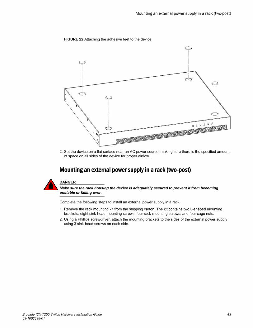
FIGURE 22 Attaching the adhesive feet to the device
2. Set the device on a flat surface near an AC power source, making sure there is the specified amountof space on all sides of the device for proper airflow.
Mounting an external power supply in a rack (two-post)
DANGERMake sure the rack housing the device is adequately secured to prevent it from becomingunstable or falling over.
Complete the following steps to install an external power supply in a rack.
1. Remove the rack mounting kit from the shipping carton. The kit contains two L-shaped mountingbrackets, eight sink-head mounting screws, four rack-mounting screws, and four cage nuts.
2. Using a Phillips screwdriver, attach the mounting brackets to the sides of the external power supplyusing 3 sink-head screws on each side.
Mounting an external power supply in a rack (two-post)
Brocade ICX 7250 Switch Hardware Installation Guide 4353-1003898-01
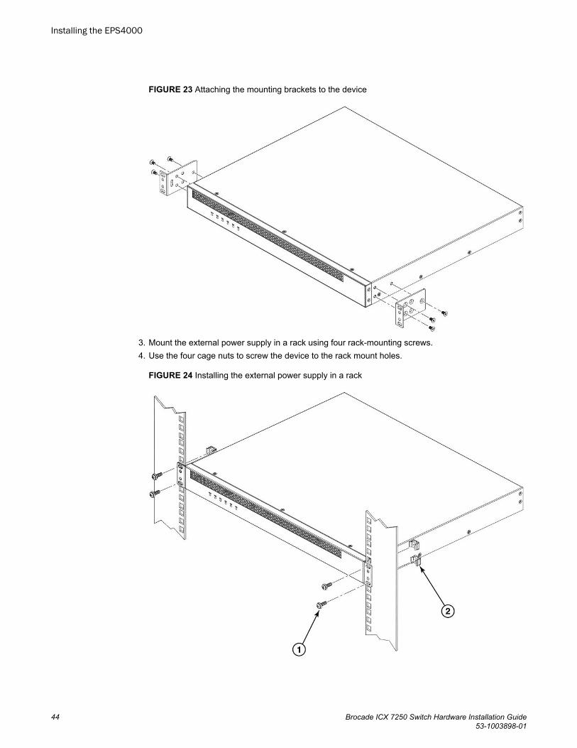
FIGURE 23 Attaching the mounting brackets to the device
3. Mount the external power supply in a rack using four rack-mounting screws.4. Use the four cage nuts to screw the device to the rack mount holes.
FIGURE 24 Installing the external power supply in a rack
Installing the EPS4000
44 Brocade ICX 7250 Switch Hardware Installation Guide53-1003898-01
1. Rack-mounting screws2. Cage nuts
5. If installing multiple external power supplies, mount them in the rack one above the other.
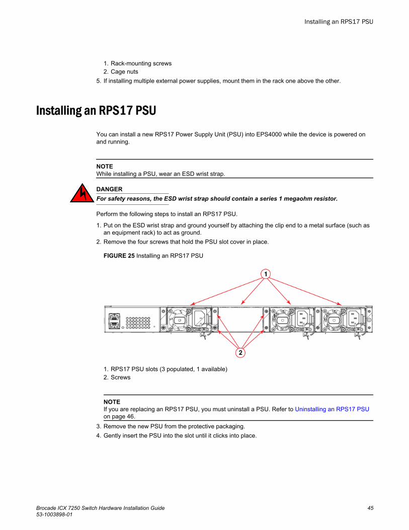
Installing an RPS17 PSU
You can install a new RPS17 Power Supply Unit (PSU) into EPS4000 while the device is powered onand running.
NOTEWhile installing a PSU, wear an ESD wrist strap.
DANGERFor safety reasons, the ESD wrist strap should contain a series 1 megaohm resistor.
Perform the following steps to install an RPS17 PSU.
1. Put on the ESD wrist strap and ground yourself by attaching the clip end to a metal surface (such asan equipment rack) to act as ground.
2. Remove the four screws that hold the PSU slot cover in place.
FIGURE 25 Installing an RPS17 PSU
1. RPS17 PSU slots (3 populated, 1 available)2. Screws
NOTEIf you are replacing an RPS17 PSU, you must uninstall a PSU. Refer to Uninstalling an RPS17 PSUon page 46.
3. Remove the new PSU from the protective packaging.4. Gently insert the PSU into the slot until it clicks into place.
Installing an RPS17 PSU
Brocade ICX 7250 Switch Hardware Installation Guide 4553-1003898-01
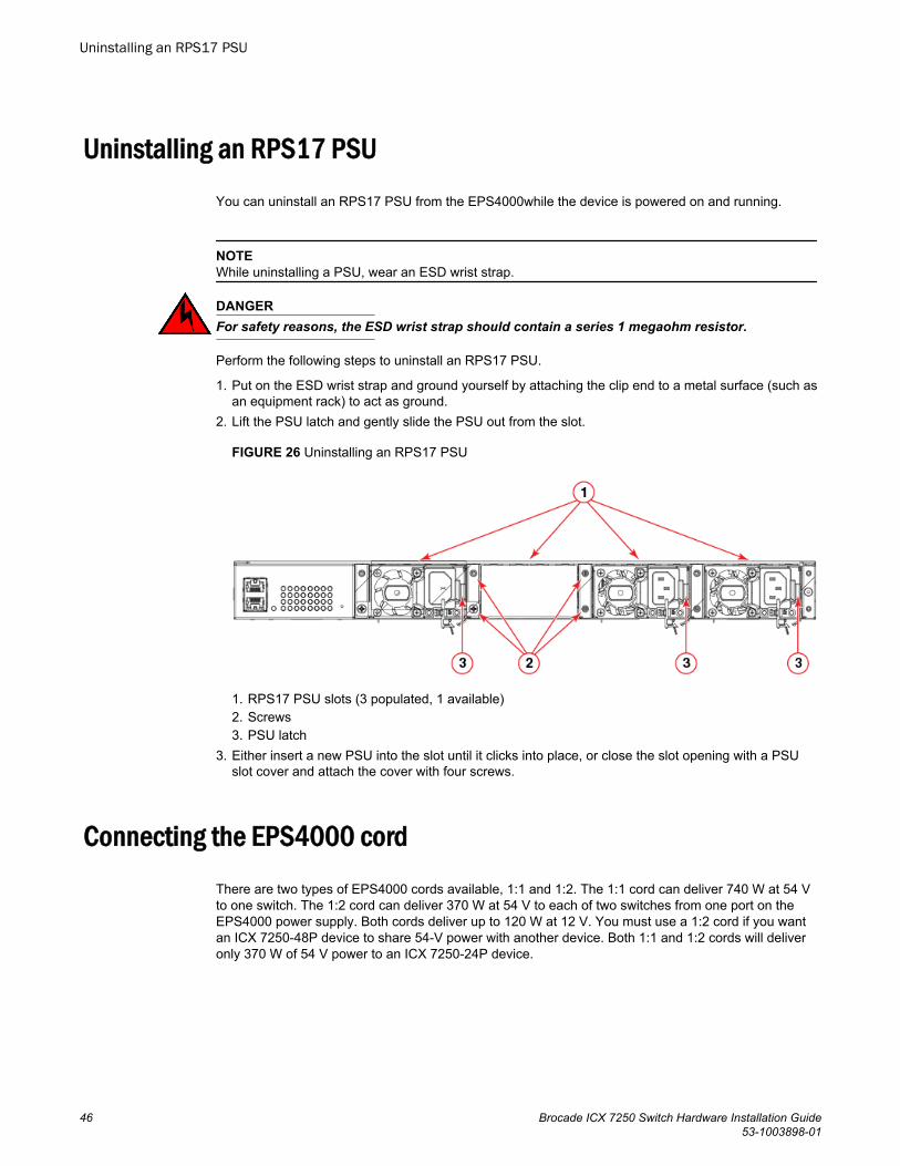
Uninstalling an RPS17 PSU
You can uninstall an RPS17 PSU from the EPS4000while the device is powered on and running.
NOTEWhile uninstalling a PSU, wear an ESD wrist strap.
DANGERFor safety reasons, the ESD wrist strap should contain a series 1 megaohm resistor.
Perform the following steps to uninstall an RPS17 PSU.
1. Put on the ESD wrist strap and ground yourself by attaching the clip end to a metal surface (such asan equipment rack) to act as ground.
2. Lift the PSU latch and gently slide the PSU out from the slot.
FIGURE 26 Uninstalling an RPS17 PSU
1. RPS17 PSU slots (3 populated, 1 available)2. Screws3. PSU latch
3. Either insert a new PSU into the slot until it clicks into place, or close the slot opening with a PSUslot cover and attach the cover with four screws.
Connecting the EPS4000 cord
There are two types of EPS4000 cords available, 1:1 and 1:2. The 1:1 cord can deliver 740 W at 54 Vto one switch. The 1:2 cord can deliver 370 W at 54 V to each of two switches from one port on theEPS4000 power supply. Both cords deliver up to 120 W at 12 V. You must use a 1:2 cord if you wantan ICX 7250-48P device to share 54-V power with another device. Both 1:1 and 1:2 cords will deliveronly 370 W of 54 V power to an ICX 7250-24P device.
Uninstalling an RPS17 PSU
46 Brocade ICX 7250 Switch Hardware Installation Guide53-1003898-01
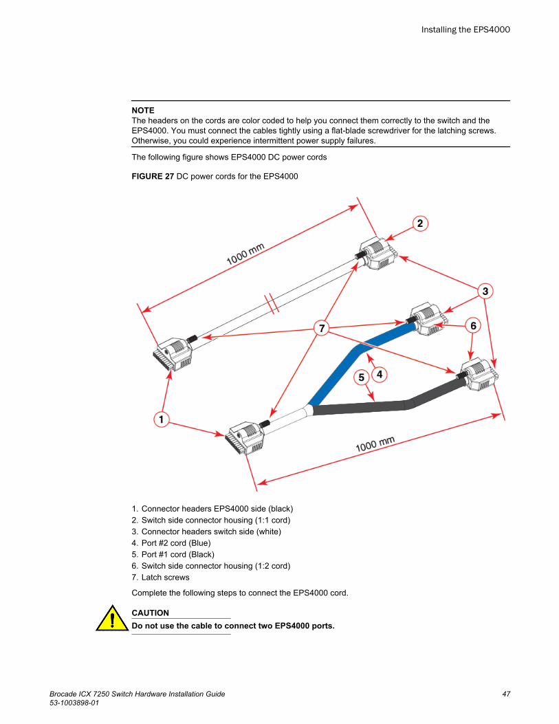
NOTEThe headers on the cords are color coded to help you connect them correctly to the switch and theEPS4000. You must connect the cables tightly using a flat-blade screwdriver for the latching screws.Otherwise, you could experience intermittent power supply failures.
The following figure shows EPS4000 DC power cords
FIGURE 27 DC power cords for the EPS4000
1. Connector headers EPS4000 side (black)2. Switch side connector housing (1:1 cord)3. Connector headers switch side (white)4. Port #2 cord (Blue)5. Port #1 cord (Black)6. Switch side connector housing (1:2 cord)7. Latch screws
Complete the following steps to connect the EPS4000 cord.
CAUTIONDo not use the cable to connect two EPS4000 ports.
Installing the EPS4000
Brocade ICX 7250 Switch Hardware Installation Guide 4753-1003898-01
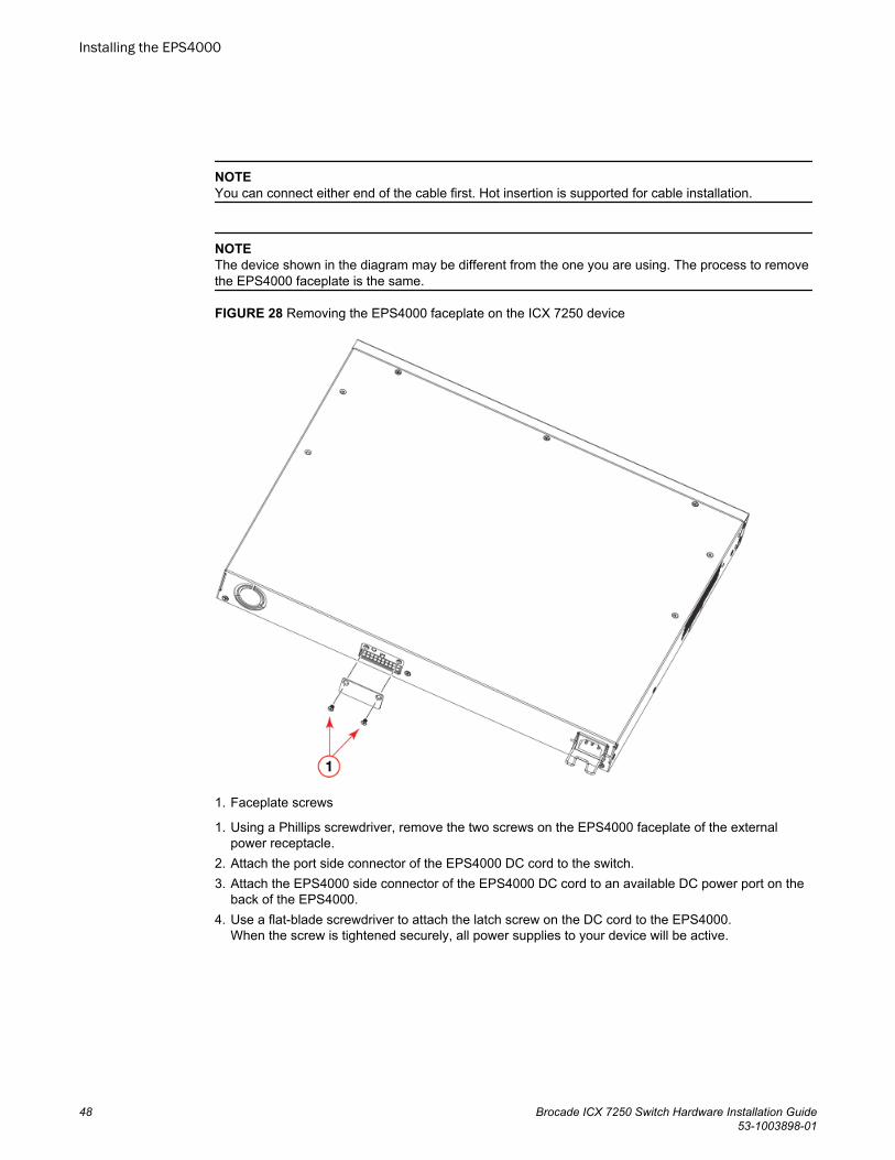
NOTEYou can connect either end of the cable first. Hot insertion is supported for cable installation.
NOTEThe device shown in the diagram may be different from the one you are using. The process to removethe EPS4000 faceplate is the same.
FIGURE 28 Removing the EPS4000 faceplate on the ICX 7250 device
1. Faceplate screws
1. Using a Phillips screwdriver, remove the two screws on the EPS4000 faceplate of the externalpower receptacle.
2. Attach the port side connector of the EPS4000 DC cord to the switch.3. Attach the EPS4000 side connector of the EPS4000 DC cord to an available DC power port on the
back of the EPS4000.4. Use a flat-blade screwdriver to attach the latch screw on the DC cord to the EPS4000.
When the screw is tightened securely, all power supplies to your device will be active.
Installing the EPS4000
48 Brocade ICX 7250 Switch Hardware Installation Guide53-1003898-01
Powering on the system
After you complete the physical installation, you can power on the system.
NOTEThe power outlet should be installed near the equipment and should be easily accessible.
1. Remove the power cord from the shipping container.2. Attach the AC power cord to the AC connector on the rear panel.3. Insert the power cord plug into a 100V-240V outlet.
NOTETo turn the system off, unplug the power cord or cords.
Connecting devices to the external power supplyComplete the following steps to connect devices to the external power supply.
1. Connect one end of the AC cord to the AC receptacle on the device, and the other end to a groundedpower outlet.
2. Connect one end of an EPS cord to the external power receptacle on the device, and the other endto an available receptacle on the external power supply.
3. Repeat Step Step 1 and Step Step 2 to connect up to the allowable maximum number of devices tothe external power supply. The maximum number of devices will depend on both the number ofpower supply units in the EPS4000 and whether you use 1:1 cords or 1:2 cords.
4. Connect one end of the AC cord to the AC receptacle on the external power supply, and the otherend to a grounded power outlet.
5. Check the LEDs on the external power supply to ensure proper operation with the devices.
Verifying proper operation
After you have installed an external power supply, verify that the device is working properly by pluggingit into a power source and verifying that it passes the self test.
1. Connect the power cord supplied with the device to the power connector on the power supply on therear of the device.
2. Insert the other end into a properly grounded electrical outlet.3. Verify that the LED for the power supply is green.4. Verify proper operation by observing the LEDs.
LEDs for linked ports will come on during the boot process, and then all LEDs will go off. Once theboot sequence is complete, LEDs for linked ports will come on again.
Powering on the system
Brocade ICX 7250 Switch Hardware Installation Guide 4953-1003898-01
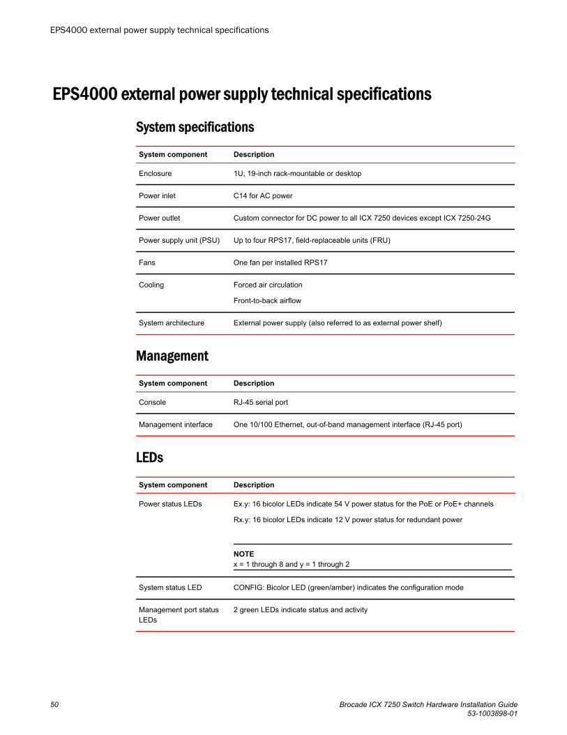
EPS4000 external power supply technical specifications
System specifications
System component Description
Enclosure 1U; 19-inch rack-mountable or desktop
Power inlet C14 for AC power
Power outlet Custom connector for DC power to all ICX 7250 devices except ICX 7250-24G
Power supply unit (PSU) Up to four RPS17, field-replaceable units (FRU)
Fans One fan per installed RPS17
Cooling Forced air circulation
Front-to-back airflow
System architecture External power supply (also referred to as external power shelf)
Management
System component Description
Console RJ-45 serial port
Management interface One 10/100 Ethernet, out-of-band management interface (RJ-45 port)
LEDs
System component Description
Power status LEDs Ex.y: 16 bicolor LEDs indicate 54 V power status for the PoE or PoE+ channels
Rx.y: 16 bicolor LEDs indicate 12 V power status for redundant power
NOTEx = 1 through 8 and y = 1 through 2
System status LED CONFIG: Bicolor LED (green/amber) indicates the configuration mode
Management port statusLEDs
2 green LEDs indicate status and activity
EPS4000 external power supply technical specifications
50 Brocade ICX 7250 Switch Hardware Installation Guide53-1003898-01
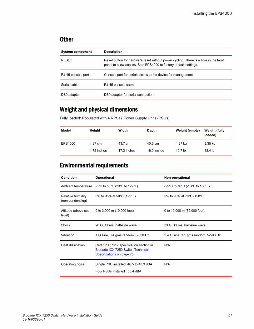
Other
System component Description
RESET Reset button for hardware reset without power cycling. There is a hole in the frontpanel to allow access. Sets EPS4000 to factory default settings.
RJ-45 console port Console port for serial access to the device for management
Serial cable RJ-45 console cable
DB9 adapter DB9 adapter for serial connection
Weight and physical dimensionsFully loaded: Populated with 4 RPS17 Power Supply Units (PSUs).
Model Height Width Depth Weight (empty) Weight (fullyloaded)
EPS4000 4.37 cm
1.72 inches
43.7 cm
17.2 inches
40.6 cm
16.0 inches
4.87 kg
10.7 lb
8.35 kg
18.4 lb
Environmental requirements
Condition Operational Non-operational
Ambient temperature -5°C to 50°C (23°F to 122°F) -25°C to 70°C (-13°F to 158°F)
Relative humidity(non-condensing)
5% to 95% at 50°C (122°F) 5% to 95% at 70°C (158°F)
Altitude (above sealevel)
0 to 3,000 m (10,000 feet) 0 to 12,000 m (39,000 feet)
Shock 20 G, 11 ms, half-sine wave 33 G, 11 ms, half-sine wave
Vibration 1 G sine, 0.4 gms random, 5-500 Hz 2.4 G sine, 1.1 gms random, 5-500 Hz
Heat dissipation Refer to RPS17 specification section in Brocade ICX 7250 Switch TechnicalSpecifications on page 75
N/A
Operating noise Single PSU installed: 46.5 to 48.3 dBA
Four PSUs installed : 53.4 dBA
N/A
Installing the EPS4000
Brocade ICX 7250 Switch Hardware Installation Guide 5153-1003898-01
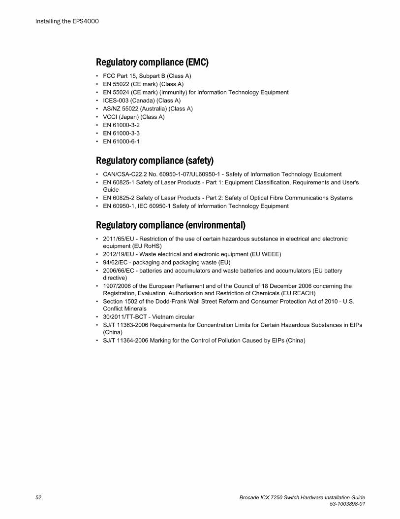
Regulatory compliance (EMC)• FCC Part 15, Subpart B (Class A)• EN 55022 (CE mark) (Class A)• EN 55024 (CE mark) (Immunity) for Information Technology Equipment• ICES-003 (Canada) (Class A)• AS/NZ 55022 (Australia) (Class A)• VCCI (Japan) (Class A)• EN 61000-3-2• EN 61000-3-3• EN 61000-6-1
Regulatory compliance (safety)• CAN/CSA-C22.2 No. 60950-1-07/UL60950-1 - Safety of Information Technology Equipment• EN 60825-1 Safety of Laser Products - Part 1: Equipment Classification, Requirements and User's
Guide• EN 60825-2 Safety of Laser Products - Part 2: Safety of Optical Fibre Communications Systems• EN 60950-1, IEC 60950-1 Safety of Information Technology Equipment
Regulatory compliance (environmental)• 2011/65/EU - Restriction of the use of certain hazardous substance in electrical and electronic
equipment (EU RoHS)• 2012/19/EU - Waste electrical and electronic equipment (EU WEEE)• 94/62/EC - packaging and packaging waste (EU)• 2006/66/EC - batteries and accumulators and waste batteries and accumulators (EU battery
directive)• 1907/2006 of the European Parliament and of the Council of 18 December 2006 concerning the
Registration, Evaluation, Authorisation and Restriction of Chemicals (EU REACH)• Section 1502 of the Dodd-Frank Wall Street Reform and Consumer Protection Act of 2010 - U.S.
Conflict Minerals• 30/2011/TT-BCT - Vietnam circular• SJ/T 11363-2006 Requirements for Concentration Limits for Certain Hazardous Substances in EIPs
(China)• SJ/T 11364-2006 Marking for the Control of Pollution Caused by EIPs (China)
Installing the EPS4000
52 Brocade ICX 7250 Switch Hardware Installation Guide53-1003898-01
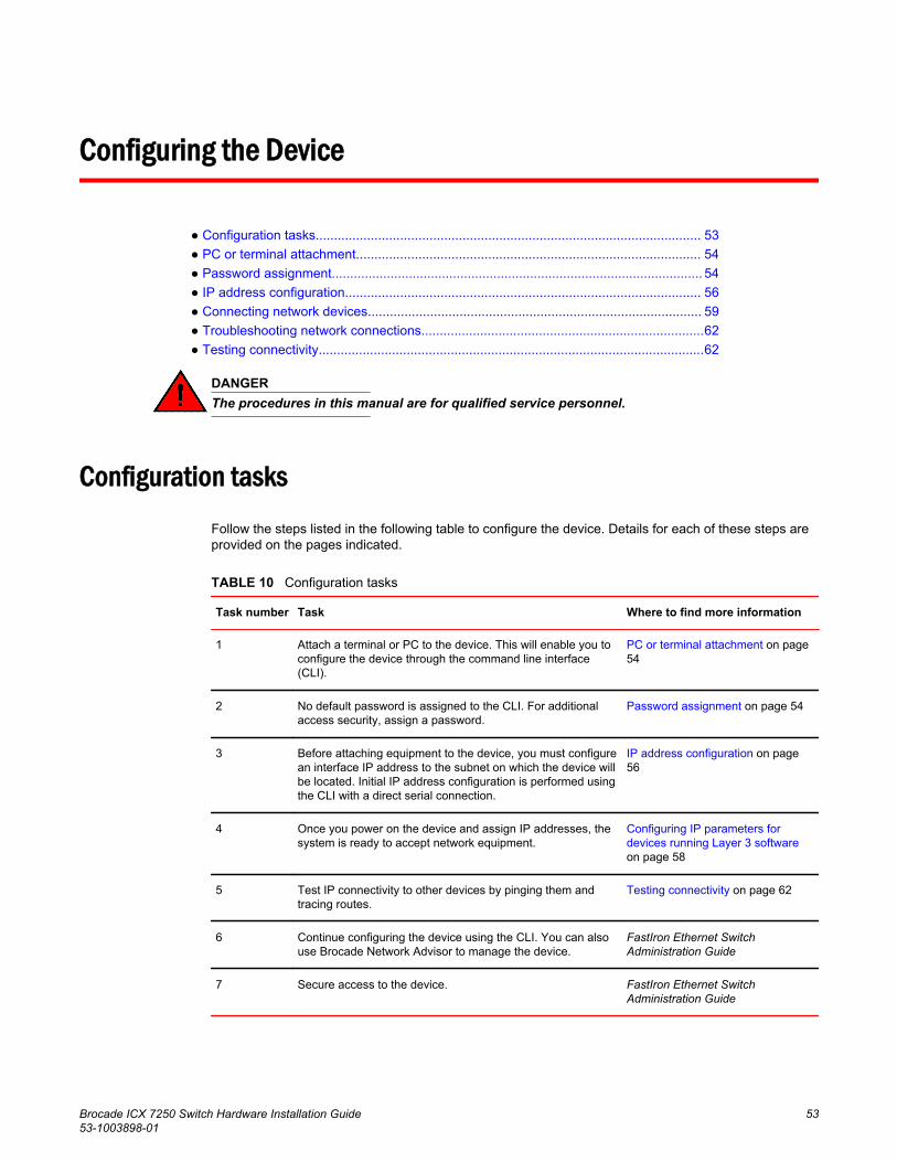
Configuring the Device
● Configuration tasks......................................................................................................... 53● PC or terminal attachment.............................................................................................. 54● Password assignment..................................................................................................... 54● IP address configuration................................................................................................. 56● Connecting network devices........................................................................................... 59● Troubleshooting network connections.............................................................................62● Testing connectivity.........................................................................................................62
DANGERThe procedures in this manual are for qualified service personnel.
Configuration tasksFollow the steps listed in the following table to configure the device. Details for each of these steps areprovided on the pages indicated.
Configuration tasks TABLE 10
Task number Task Where to find more information
1 Attach a terminal or PC to the device. This will enable you toconfigure the device through the command line interface(CLI).
PC or terminal attachment on page54
2 No default password is assigned to the CLI. For additionalaccess security, assign a password.
Password assignment on page 54
3 Before attaching equipment to the device, you must configurean interface IP address to the subnet on which the device willbe located. Initial IP address configuration is performed usingthe CLI with a direct serial connection.
IP address configuration on page56
4 Once you power on the device and assign IP addresses, thesystem is ready to accept network equipment.
Configuring IP parameters fordevices running Layer 3 softwareon page 58
5 Test IP connectivity to other devices by pinging them andtracing routes.
Testing connectivity on page 62
6 Continue configuring the device using the CLI. You can alsouse Brocade Network Advisor to manage the device.
FastIron Ethernet SwitchAdministration Guide
7 Secure access to the device. FastIron Ethernet SwitchAdministration Guide
Brocade ICX 7250 Switch Hardware Installation Guide 5353-1003898-01
PC or terminal attachment
You can access the CLI by attaching a serial cable to the console port. After you assign an IP address,you can access the system through Telnet or Brocade Network Advisor.
Complete the following steps to attach a management station to the console port.
1. Connect a PC or terminal to the console (mini-USB) port of the device.
To connect the console port to a DB9 port, you need a cable with mini-USB and DB9 connectors.
For information about locating the serial port, refer to Network and management interfaces on page14.
The serial port has a mini-USB connector. For port pinout information, refer to Brocade ICX 7250Switch Technical Specifications on page 75.
NOTEYou must run a terminal emulation program on the PC.
2. Launch the terminal emulation program and set the following session parameters:
• Baud: 9600 bps• Data bits: 8• Parity: None• Stop bits: 1• Flow control: None
The console serial communication port serves as a connection point for management by a PC orSNMP workstation. When you establish the serial connection to the system, press Enter to displaythe CLI prompt in the terminal emulation window, as shown in the following example.
device>If you see this prompt, you are connected to the system and can proceed to Password assignmenton page 54.
You can customize the prompt by changing the system name. For more information, refer to theFastIron Ethernet Switch Administration Guide.
If you do not see the prompt, make sure the cable is securely connected to your PC and to theBrocade system.
Check the settings in your terminal emulation program. In addition to the previously configuredsession settings, make sure the terminal emulation session is running on the same serial port youattached to the Brocade system.
Password assignmentBy default, the CLI is not protected by passwords. To secure CLI access, Brocade stronglyrecommends assigning passwords. Refer to the FastIron Ethernet Switch Administration Guide.
NOTEYou can assign passwords using Brocade Network Advisor if an enable password for a Super Userhas been configured on the device.
PC or terminal attachment
54 Brocade ICX 7250 Switch Hardware Installation Guide53-1003898-01
The CLI contains the following access levels:
• User EXEC: The level you enter when you first start a CLI session. At this level, you can view somesystem information but you cannot configure system or port parameters.
• Privileged EXEC: This level is also called the Enable level and can be secured by a password. Youcan perform tasks such as managing files on the flash module, saving the system configuration toflash, and clearing caches at this level.
• CONFIG: The configuration level. This level allows you to configure the system IP address andconfigure switching and routing features. To access the CONFIG mode, you must already be loggedin to the privileged EXEC level.
You can set the following levels of Enable passwords:
• Super User: Allows complete read-and-write access to the system. This is generally for systemadministrators and is the only password level that allows you to configure passwords.
NOTEYou must set a Super User password before you can set other types of passwords.
• Port Configuration: Allows read-and-write access for specific ports but not for global (system-wide)parameters.
• Read-Only: Allows access to the privileged EXEC mode and CONFIG mode but only with readaccess.
Assigning passwordsComplete the following steps to set passwords.
NOTEDepending on the device you purchased, and the code (Layer 2 or Layer 3) loaded on your system, therouter prompt is displayed accordingly. For example, for an ICX 7250-48P device running Layer 3 codeon the device, the router prompt displays ICX 7250-48P Router> at the CLI level.
1. At the opening CLI prompt, enter the following command to change to the Privileged EXEC mode:
device> enable2. Access the configuration mode of the CLI by entering the following command:
device# configure terminal3. Enter the following command to set the Super User password:
device(config)# enable super-user-password joe
NOTEYou must set the Super User password before you can set other types of passwords.
4. Enter the following commands to set the port configuration and read-only passwords:
device(config)# enable port-config-password johndevice(config)# enable read-only-password sam
NOTEIf you forget your Super User password, refer to Recovering from a lost password on page 56.
Passwords can be up to 32 characters long.
Assigning passwords
Brocade ICX 7250 Switch Hardware Installation Guide 5553-1003898-01
Recovering from a lost passwordBy default, the CLI does not require passwords. However, if a password has been configured for thedevice but the password has been lost, you can regain Super User access to the device using thefollowing procedure.
NOTERecovery from a lost password requires direct access to the serial port and a system reset.
1. Start a CLI session over the serial interface to the Brocade device.2. Reboot the device.3. While the system is booting, before the initial system prompt appears, enter b to enter the boot
monitor mode.4. Enter no password. (You cannot abbreviate this command.)5. Enter boot. This command causes the device to bypass the system password check.
After the console prompt reappears, assign a new password.
IP address configurationYou must configure at least one IP address using the serial connection to the CLI before you canmanage the system using the other management interfaces.
Brocade devices support both classical IP network masks (Class A, B, and C subnet masks, and soon) and Classless Interdomain Routing (CIDR) network prefix masks.
• To enter a classical IP network mask, enter the mask in IP address format. For example, enter"10.157.22.99 255.255.255.0" for an IP address with a Class C subnet mask.
• To enter a prefix number for a network mask, enter a forward slash (/) and the number of bits in themask immediately after the IP address. For example, enter "10.157.22.99/24" for an IP address thathas a network mask with 24 significant ("mask") bits.
By default, the CLI displays network masks in classical IP address format (for example,255.255.255.0). You can change the display to the prefix format. Refer to the FastIron Ethernet SwitchAdministration Guide.
Devices running Layer 2 softwareUse the following procedure to configure an IP address on a device running Layer 2 software.
1. At the opening CLI prompt, enter enable.
device> enable2. Enter the following command at the Privileged EXEC level prompt, and then press Enter . This
command erases the factory test configuration if still present.
device# erase startup-config
Recovering from a lost password
56 Brocade ICX 7250 Switch Hardware Installation Guide53-1003898-01
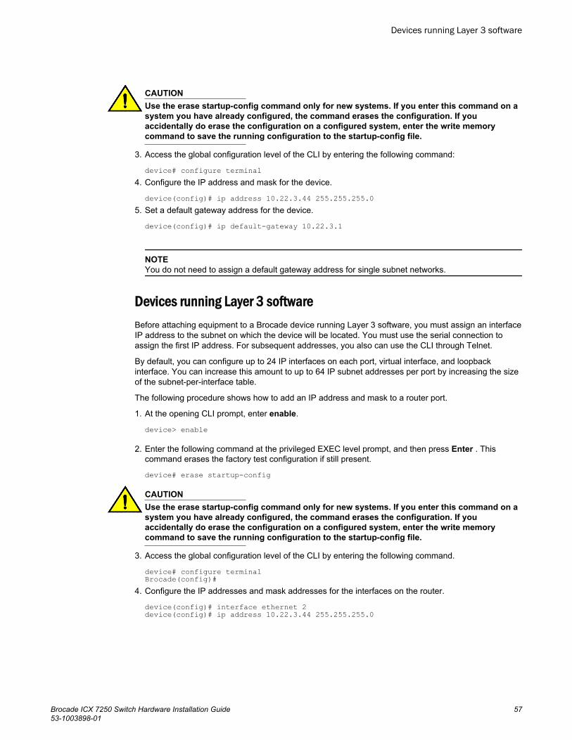
CAUTIONUse the erase startup-config command only for new systems. If you enter this command on asystem you have already configured, the command erases the configuration. If youaccidentally do erase the configuration on a configured system, enter the write memorycommand to save the running configuration to the startup-config file.
3. Access the global configuration level of the CLI by entering the following command:
device# configure terminal 4. Configure the IP address and mask for the device.
device(config)# ip address 10.22.3.44 255.255.255.05. Set a default gateway address for the device.
device(config)# ip default-gateway 10.22.3.1
NOTEYou do not need to assign a default gateway address for single subnet networks.
Devices running Layer 3 softwareBefore attaching equipment to a Brocade device running Layer 3 software, you must assign an interfaceIP address to the subnet on which the device will be located. You must use the serial connection toassign the first IP address. For subsequent addresses, you also can use the CLI through Telnet.
By default, you can configure up to 24 IP interfaces on each port, virtual interface, and loopbackinterface. You can increase this amount to up to 64 IP subnet addresses per port by increasing the sizeof the subnet-per-interface table.
The following procedure shows how to add an IP address and mask to a router port.
1. At the opening CLI prompt, enter enable.
device> enable
2. Enter the following command at the privileged EXEC level prompt, and then press Enter . Thiscommand erases the factory test configuration if still present.
device# erase startup-config
CAUTIONUse the erase startup-config command only for new systems. If you enter this command on asystem you have already configured, the command erases the configuration. If youaccidentally do erase the configuration on a configured system, enter the write memorycommand to save the running configuration to the startup-config file.
3. Access the global configuration level of the CLI by entering the following command.
device# configure terminal Brocade(config)#
4. Configure the IP addresses and mask addresses for the interfaces on the router.
device(config)# interface ethernet 2device(config)# ip address 10.22.3.44 255.255.255.0
Devices running Layer 3 software
Brocade ICX 7250 Switch Hardware Installation Guide 5753-1003898-01
NOTEYou can use the ip address ip-addr/mask-bits command if you know the subnet mask length. In theprevious example, you could enter ip address 10.22.3.44/24.
Use the secondary option of the ip address command parameter if you have already configuredan IP address within the same subnet on the interface.
Configuring IP parameters for devices running Layer 3 software
You must configure IP parameters for devices running Layer 3 software.
Configuring IP addresses
You can configure an IP address on the following types of Layer 3 interfaces:
• Ethernet port• Virtual routing interface (also called a Virtual Ethernet or "VE")• Loopback interface
By default, you can have up to 24 IP addresses on each interface, but you can increase this number to128 IP addresses.
NOTEOnce you configure a virtual routing interface on a VLAN, you cannot configure Layer 3 interfaceparameters on individual ports in the VLAN. Instead, you must configure the parameters on the virtualrouting interface itself.
Assigning an IP address to an Ethernet port
Enter the following commands to assign an IP address to port 1/1/1.
device(config)# interface ethernet 1/1/1device(config)# ip address 10.45.6.1 255.255.255.0You also can enter the IP address and mask in CIDR format.
device># ip address 10.45.6.1/24
Assigning an IP address to a loopback interface
Loopback interfaces are always up, regardless of the states of physical interfaces. They can addstability to the network because they are not subject to route flap problems that can occur due tounstable links between a Layer 3 device and other devices. You can configure up to four loopbackinterfaces on a Layer 3 device.
You can add up to 24 IP addresses to each loopback interface.
NOTEIf you configure the device to use a loopback interface to communicate with a BGP4 neighbor, youmust also configure a loopback interface on the neighbor and configure the neighbor to use thatloopback interface to communicate with the Brocade device.
Configuring IP parameters for devices running Layer 3 software
58 Brocade ICX 7250 Switch Hardware Installation Guide53-1003898-01
To add a loopback interface, enter the interface loopback num and ip address num commands similarto the following example.
device(config)# exitdevice(config)# interface loopback 1device(config)# ip address 10.0.0.1/24You can specify from 1 through the maximum number of virtual interfaces supported on the device byusing the interface loopback num command.. To display the maximum number of virtual interfacessupported on the device, enter the show default values command.
Assigning an IP address to a virtual routing interface
A virtual interface is a logical port associated with a Layer 3 Virtual LAN (VLAN) configured on a Layer 3device. You can configure routing parameters on the virtual interface to enable the Layer 3 device toroute protocol traffic from one Layer 3 VLAN to the other, without using an external router.
NOTEThe device uses the lowest MAC address on the device (the MAC address of port 1 or 1/1/1) as theMAC address for all ports within all virtual interfaces you configure on the device.
Enter commands similar to the following to add a virtual interface to a VLAN and configure an IPaddress on the interface.
device(config)# vlan 2 name IP-Subnet_10.1.2.1/24device(config-vlan-2)# untag 1/1/1 to 1/1/4device(config-vlan-2)# router-interface ve1device(config-vlan-2)# interface ve1device(config-vif-1)# ip address 10.1.2.1/24The first two commands in this example create a Layer 3 protocol-based VLAN named "IP-Subnet_10.1.2.1/24" and add a range of untagged ports to the VLAN. The router-interface commandcreates virtual interface 1 as the routing interface for the VLAN. The last two commands change to theinterface configuration level for the virtual interface and assign an IP address to the interface.
Deleting an IP address
Enter a command similar to the following to delete an IP address.
device(config-if-1/1/1)# no ip address 10.1.2.1This command deletes IP address 10.1.2.1. You do not need to enter the subnet mask.
To delete all IP addresses from an interface, enter the following command.
device(config-if-1/1/1)# no ip address *
Connecting network devicesBrocade devices support connections to other vendors’ routers, switches, and hubs, as well otherBrocade devices.
Deleting an IP address
Brocade ICX 7250 Switch Hardware Installation Guide 5953-1003898-01
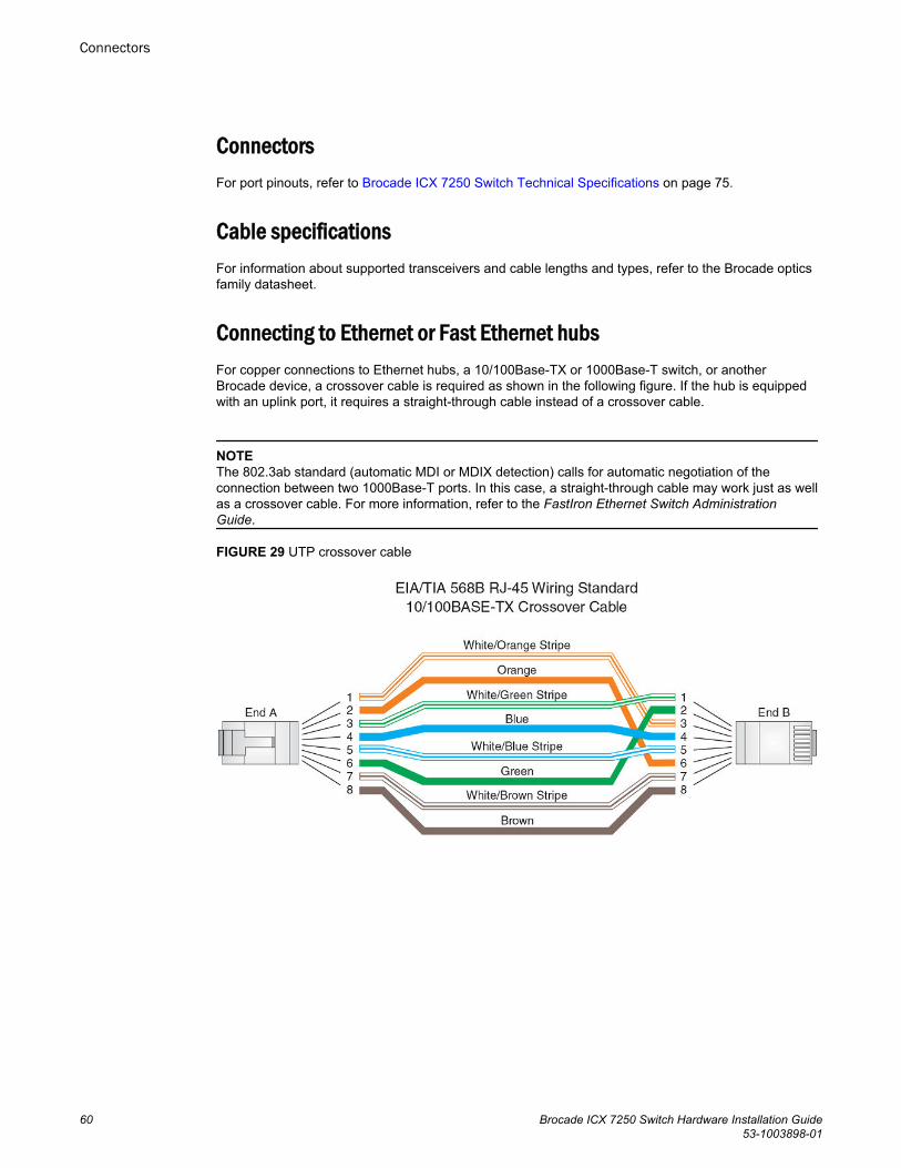
ConnectorsFor port pinouts, refer to Brocade ICX 7250 Switch Technical Specifications on page 75.
Cable specificationsFor information about supported transceivers and cable lengths and types, refer to the Brocade opticsfamily datasheet.
Connecting to Ethernet or Fast Ethernet hubsFor copper connections to Ethernet hubs, a 10/100Base-TX or 1000Base-T switch, or anotherBrocade device, a crossover cable is required as shown in the following figure. If the hub is equippedwith an uplink port, it requires a straight-through cable instead of a crossover cable.
NOTEThe 802.3ab standard (automatic MDI or MDIX detection) calls for automatic negotiation of theconnection between two 1000Base-T ports. In this case, a straight-through cable may work just as wellas a crossover cable. For more information, refer to the FastIron Ethernet Switch AdministrationGuide.
FIGURE 29 UTP crossover cable
Connectors
60 Brocade ICX 7250 Switch Hardware Installation Guide53-1003898-01
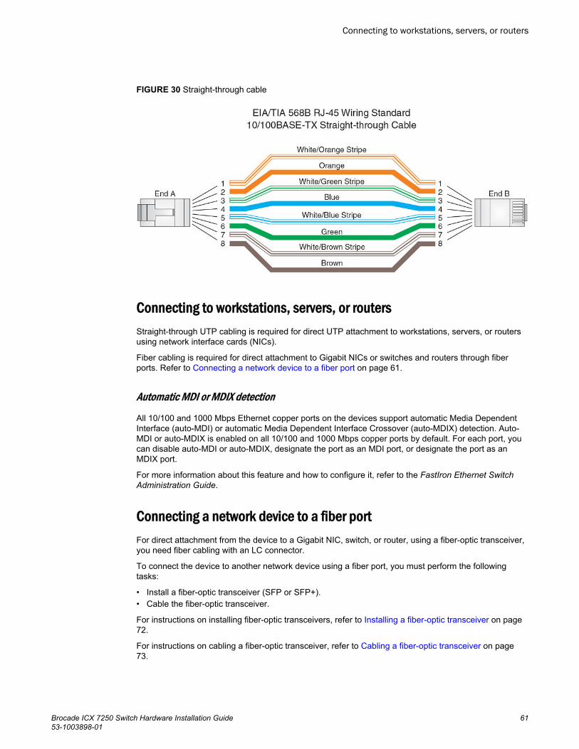
FIGURE 30 Straight-through cable
Connecting to workstations, servers, or routersStraight-through UTP cabling is required for direct UTP attachment to workstations, servers, or routersusing network interface cards (NICs).
Fiber cabling is required for direct attachment to Gigabit NICs or switches and routers through fiberports. Refer to Connecting a network device to a fiber port on page 61.
Automatic MDI or MDIX detection
All 10/100 and 1000 Mbps Ethernet copper ports on the devices support automatic Media DependentInterface (auto-MDI) or automatic Media Dependent Interface Crossover (auto-MDIX) detection. Auto-MDI or auto-MDIX is enabled on all 10/100 and 1000 Mbps copper ports by default. For each port, youcan disable auto-MDI or auto-MDIX, designate the port as an MDI port, or designate the port as anMDIX port.
For more information about this feature and how to configure it, refer to the FastIron Ethernet SwitchAdministration Guide.
Connecting a network device to a fiber portFor direct attachment from the device to a Gigabit NIC, switch, or router, using a fiber-optic transceiver,you need fiber cabling with an LC connector.
To connect the device to another network device using a fiber port, you must perform the followingtasks:
• Install a fiber-optic transceiver (SFP or SFP+).• Cable the fiber-optic transceiver.
For instructions on installing fiber-optic transceivers, refer to Installing a fiber-optic transceiver on page72.
For instructions on cabling a fiber-optic transceiver, refer to Cabling a fiber-optic transceiver on page73.
Connecting to workstations, servers, or routers
Brocade ICX 7250 Switch Hardware Installation Guide 6153-1003898-01
For instructions on cleaning a fiber-optic module, refer to Cleaning the fiber-optic connectors on page74.
Troubleshooting network connections• For the indicated port, verify that both ends of the cabling (at the device and the connected device)
are snug.• Verify that the device and the connected device are both powered on and operating correctly.• Verify that you have used the correct cable type for the connection:
‐ For twisted-pair connections to an end node, use straight-through cabling.‐ For fiber-optic connections, verify that the transmit port on the device is connected to the receive
port on the connected device, and that the receive port on the device is connected to the transmitport on the connected device.
• Use the CLI to verify that the port has not been disabled through a configuration change. If youhave configured an IP address on the device, you also can use Brocade Network Advisor.
• If the other procedures do not resolve the problem, try using a different port or a different cable.• If a 1-Gbps optic transceiver is inserted into an ICX 7250 device, you must configure the port using
the speed-duplex 1000-full-master command at the interface level.
Digital optical monitoring
NOTE10 Gbps optical transceivers are not supported on ICX 7250-24G devices.
You can configure your device to monitor optical transceivers in the system, either globally or byspecified port. When this feature is enabled, the system monitors the temperature and signal powerlevels for the optical transceivers in the specified ports. Console messages and syslog messages aresent when optical operating conditions fall below or rise above the SFP and SFP+ manufacturer’srecommended thresholds. For more information about digital optical monitoring, refer to the FastIronEthernet Switch Administration Guide.
Testing connectivityTest for connectivity by observing the LEDs related to network connection.
Pinging an IP addressTo verify that a device can reach another device through the network, enter a command similar to thefollowing at any level of the CLI.
device> ping 10.33.4.7
NOTEIf you address the ping to the IP broadcast address, the device lists the first four responses.
Troubleshooting network connections
62 Brocade ICX 7250 Switch Hardware Installation Guide53-1003898-01
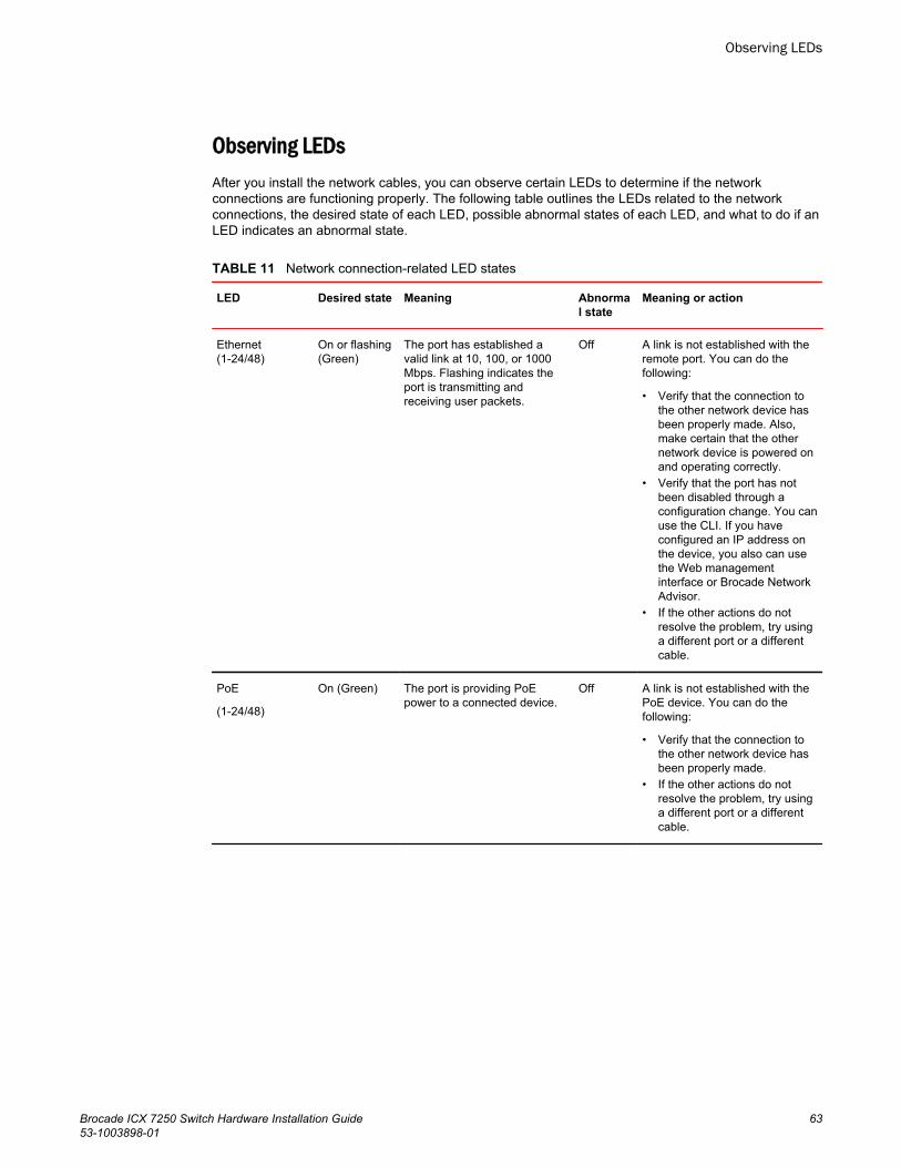
Observing LEDsAfter you install the network cables, you can observe certain LEDs to determine if the networkconnections are functioning properly. The following table outlines the LEDs related to the networkconnections, the desired state of each LED, possible abnormal states of each LED, and what to do if anLED indicates an abnormal state.
Network connection-related LED states TABLE 11
LED Desired state Meaning Abnormal state
Meaning or action
Ethernet(1-24/48)
On or flashing(Green)
The port has established avalid link at 10, 100, or 1000Mbps. Flashing indicates theport is transmitting andreceiving user packets.
Off A link is not established with theremote port. You can do thefollowing:
• Verify that the connection tothe other network device hasbeen properly made. Also,make certain that the othernetwork device is powered onand operating correctly.
• Verify that the port has notbeen disabled through aconfiguration change. You canuse the CLI. If you haveconfigured an IP address onthe device, you also can usethe Web managementinterface or Brocade NetworkAdvisor.
• If the other actions do notresolve the problem, try usinga different port or a differentcable.
PoE
(1-24/48)
On (Green) The port is providing PoEpower to a connected device.
Off A link is not established with thePoE device. You can do thefollowing:
• Verify that the connection tothe other network device hasbeen properly made.
• If the other actions do notresolve the problem, try usinga different port or a differentcable.
Observing LEDs
Brocade ICX 7250 Switch Hardware Installation Guide 6353-1003898-01

Network connection-related LED states (Continued)TABLE 11
LED Desired state Meaning Abnormal state
Meaning or action
SFP (X1 - X4) forICX 7250-24Gdevices
SFP+ (X1 - X8)for all other ICX7250 devices
On or flashing(Green orYellow)
Flashing yellow indicates theport is transmitting andreceiving user packets at 1Gbps.
The SFP+ port is operating at10 Gbps. Flashing greenindicates the port istransmitting and receiving userpackets at 10 Gbps.
Off A link is not established with theremote port. You can do thefollowing:
• Verify that the connection tothe other network device hasbeen properly made. Also,make certain that the othernetwork device is powered onand operating correctly.
• Verify that the transmit port onthe device is connected to thereceive port on the othernetwork device, and that thereceive port on the device isconnected to the transmit porton the other network device. Ifyou are not certain, removethe two cable connectors fromthe port connector andreinsert them in the portconnector, reversing theirorder.
• Dust may have accumulatedin the cable connector or portconnector. For informationabout cleaning theconnectors, refer to Cleaningthe fiber-optic connectors onpage 74.
• Verify that the port has notbeen disabled through aconfiguration change.
• Ensure that the SFP+transceivers in both ends areof the same optic type (forexample, SR, LR, LRM).
• If the other actions do notresolve the problem, try usinga different port or a differentcable.
If a problem persists after taking these actions, contact Brocade Technical Support.
Tracing a routeTo determine the path through which a Brocade device can reach another device, enter a commandsimilar to the following at any level of the CLI on the device.
device> traceroute 10.33.4.7The CLI displays trace route information for each hop as soon as the information is received.Traceroute requests display all responses to a given TTL. In addition, if there are multiple equal-costroutes to the destination, the Brocade device displays up to two responses by default.
Tracing a route
64 Brocade ICX 7250 Switch Hardware Installation Guide53-1003898-01
Managing an ICX 7250 Device
● Managing temperature settings.......................................................................................65● Displaying CPU usage.................................................................................................... 69● Removing MAC address entries..................................................................................... 69
DANGERThe procedures in this manual are for qualified service personnel.
Managing temperature settingsThe device contains temperature sensors that the software reads based on a configurable device polltime. The devices have two automatic speed fan control settings based on the temperature. To protectthe device from overheating, the following temperature threshold levels exist:
• The warning level is the temperature at which the device generates a syslog message. It isconfigurable up to 100°C.
• The shutdown level is the temperature at which the device reboots. It is set by the device and is notconfigurable. When the device temperature reaches the shutdown level, it generates a warningmessage that the device’s temperature is over the shutdown level and the device shuts down in fiveminutes. The system restarts five minutes after the device reaches the temperature shutdown level.
Temperature threshold levelsThe switch fans have two speeds, low and high. The fan speed settings are set by the device, and arenot configurable.
During system bootup, the fans run at high speed. If the switch does not detect any fans, the switchshuts down.
After bootup, the fans operate at low speed when the temperature of the switch is below the high limittemperature that is specified in the following table. If the switch reaches the high limit temperature, thefans operate at high speed until the switch reaches the low limit temperature specified in the table, atwhich time the fans decrease to low speed.
If the switch reaches or exceeds the critical (shutdown) temperature for two minutes, the switch shutsdown.
NOTEIn addition to the overall temperature of the module, the ICX 7250-24P and ICX 7250-48P modulesmonitor the temperature of the Power Over Ethernet (PoE) power supply unit (PSU). When the low limitand high limit temperatures are reached, the PoE PSU fans change speed using the same algorithm asthe module fans. There is no change to the Critical (shutdown) temperature value for these modules.
Brocade ICX 7250 Switch Hardware Installation Guide 6553-1003898-01
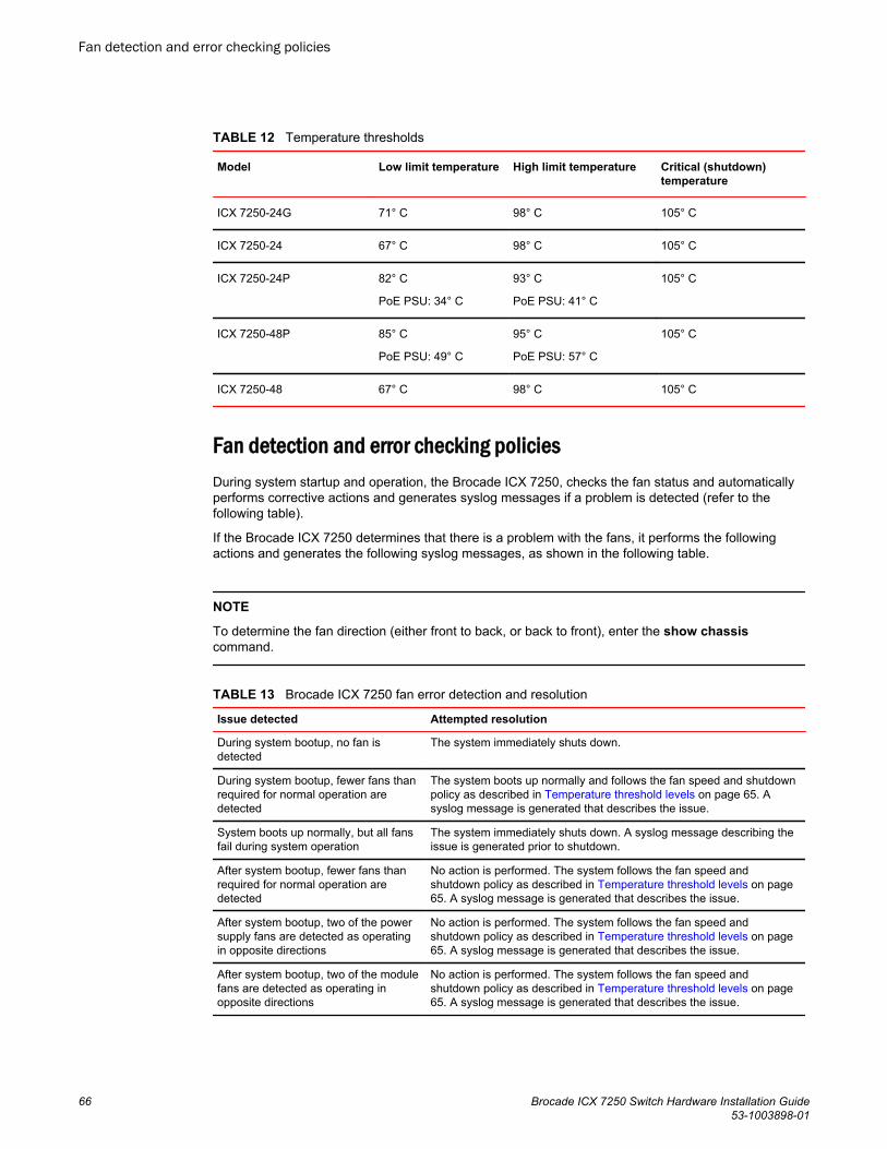
Temperature thresholdsTABLE 12
Model Low limit temperature High limit temperature Critical (shutdown)temperature
ICX 7250-24G 71° C 98° C 105° C
ICX 7250-24 67° C 98° C 105° C
ICX 7250-24P 82° C
PoE PSU: 34° C
93° C
PoE PSU: 41° C
105° C
ICX 7250-48P 85° C
PoE PSU: 49° C
95° C
PoE PSU: 57° C
105° C
ICX 7250-48 67° C 98° C 105° C
Fan detection and error checking policiesDuring system startup and operation, the Brocade ICX 7250, checks the fan status and automaticallyperforms corrective actions and generates syslog messages if a problem is detected (refer to thefollowing table).
If the Brocade ICX 7250 determines that there is a problem with the fans, it performs the followingactions and generates the following syslog messages, as shown in the following table.
NOTE
To determine the fan direction (either front to back, or back to front), enter the show chassiscommand.
Brocade ICX 7250 fan error detection and resolutionTABLE 13
Issue detected Attempted resolution
During system bootup, no fan isdetected
The system immediately shuts down.
During system bootup, fewer fans thanrequired for normal operation aredetected
The system boots up normally and follows the fan speed and shutdownpolicy as described in Temperature threshold levels on page 65. Asyslog message is generated that describes the issue.
System boots up normally, but all fansfail during system operation
The system immediately shuts down. A syslog message describing theissue is generated prior to shutdown.
After system bootup, fewer fans thanrequired for normal operation aredetected
No action is performed. The system follows the fan speed andshutdown policy as described in Temperature threshold levels on page65. A syslog message is generated that describes the issue.
After system bootup, two of the powersupply fans are detected as operatingin opposite directions
No action is performed. The system follows the fan speed andshutdown policy as described in Temperature threshold levels on page65. A syslog message is generated that describes the issue.
After system bootup, two of the modulefans are detected as operating inopposite directions
No action is performed. The system follows the fan speed andshutdown policy as described in Temperature threshold levels on page65. A syslog message is generated that describes the issue.
Fan detection and error checking policies
66 Brocade ICX 7250 Switch Hardware Installation Guide53-1003898-01
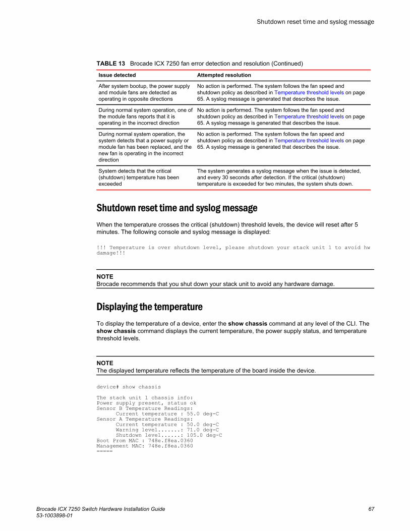
Brocade ICX 7250 fan error detection and resolution (Continued)TABLE 13
Issue detected Attempted resolution
After system bootup, the power supplyand module fans are detected asoperating in opposite directions
No action is performed. The system follows the fan speed andshutdown policy as described in Temperature threshold levels on page65. A syslog message is generated that describes the issue.
During normal system operation, one ofthe module fans reports that it isoperating in the incorrect direction
No action is performed. The system follows the fan speed andshutdown policy as described in Temperature threshold levels on page65. A syslog message is generated that describes the issue.
During normal system operation, thesystem detects that a power supply ormodule fan has been replaced, and thenew fan is operating in the incorrectdirection
No action is performed. The system follows the fan speed andshutdown policy as described in Temperature threshold levels on page65. A syslog message is generated that describes the issue.
System detects that the critical(shutdown) temperature has beenexceeded
The system generates a syslog message when the issue is detected,and every 30 seconds after detection. If the critical (shutdown)temperature is exceeded for two minutes, the system shuts down.
Shutdown reset time and syslog messageWhen the temperature crosses the critical (shutdown) threshold levels, the device will reset after 5minutes. The following console and syslog message is displayed:
!!! Temperature is over shutdown level, please shutdown your stack unit 1 to avoid hw damage!!!
NOTEBrocade recommends that you shut down your stack unit to avoid any hardware damage.
Displaying the temperatureTo display the temperature of a device, enter the show chassis command at any level of the CLI. Theshow chassis command displays the current temperature, the power supply status, and temperaturethreshold levels.
NOTEThe displayed temperature reflects the temperature of the board inside the device.
device# show chassisThe stack unit 1 chassis info: Power supply present, status okSensor B Temperature Readings: Current temperature : 55.0 deg-CSensor A Temperature Readings: Current temperature : 50.0 deg-C Warning level.......: 71.0 deg-C Shutdown level......: 105.0 deg-CBoot Prom MAC : 748e.f8ea.0360Management MAC: 748e.f8ea.0360=====
Shutdown reset time and syslog message
Brocade ICX 7250 Switch Hardware Installation Guide 6753-1003898-01

Displaying syslog messages for temperatureThe software sends a syslog message and an SNMP trap if the temperature crosses the warning orshutdown thresholds. If you have configured the device to use a syslog server or SNMP trap receiver,refer to the documentation for the server or receiver.
To display the system log, enter the show log command at any CLI level.
device# show log Syslog logging: enabled (0 messages dropped, 0 flushes, 0 overruns)Buffer logging: level ACDMEINW, 20 messages loggedlevel code: A=alert C=critical D=debugging M=emergency E=error I=informational N=notification W=warningStatic Log Buffer:1d02h07m29s:A:System: Stack unit 1 Temperature 60.0 C degrees, warning level 55.0 C degrees, shutdown level 65.0 C degrees1d02h07m29s:W:System: Temperature is over warning level on unit 1Dec 1 10:16:34:A:System: Stack unit 2 Temperature 46.0 C degrees, warning level 70.0 C degrees, shutdown level 80.0 C degreesDec 1 10:16:34:A:System: Temperature on Unit 2 is over shutdown level, system is going to be reset in 2 secondsDynamic Log Buffer (50 lines):0d00h00m53s:I:STP: VLAN 1 Port 1/2/2 Bridge TC Event (FwdDlyExpiry)0d00h00m53s:I:STP: VLAN 1 Port 1/2/2 STP State -> FORWARDING (FwdDlyExpiry)0d00h00m37s:I:STP: VLAN 1 Port 1/2/2 STP State -> LEARNING (FwdDlyExpiry)0d00h00m26s:I:STP: VLAN 1 Port 1/2/3 STP State -> FORWARDING (FwdDlyExpiry)0d00h00m26s:I:STP: VLAN 1 Port 1/1/1 STP State -> FORWARDING (FwdDlyExpiry)0d00h00m24s:I:STP: VLAN 1 Port 1/2/3 STP State -> LEARNING (FwdDlyExpiry)0d00h00m24s:I:STP: VLAN 1 Port 1/1/1 STP State -> LEARNING (FwdDlyExpiry)0d00h00m23s:I:STP: VLAN 1 Port 1/2/4 STP State -> BLOCKING (MakeBlking)0d00h00m22s:I:System: Interface ethernet 1/2/4, state up0d00h00m22s:I:STP: VLAN 1 Port 1/2/4 STP State -> LISTENING (MakeFwding)0d00h00m22s:I:System: Interface ethernet 1/2/3, state up
Changing the temperature warning levelTo change the temperature at which the device sends a syslog message and an SNMP trap, enter thetemperature warning stack-id value command at the privileged EXEC level of the CLI.
device# temperature warning 1 82The stack-id variable can be a value from 1 through 12.
The value variable is the temperature warning level, in Celsius. You cannot set this level higher thanthe maximum value allowed by your device. The temperature warning level must be at least fivedegrees Celsius less than the temperature shutdown level, which is automatically set by the device.
The following console and syslog message is displayed when the temperature reaches the warninglevel:
!!! Temperature is over warning level on stack unit 1!!!
Changing the temperature poll timeBy default, the software polls the temperature sensor every 60 seconds to get the current temperature.This poll rate is controlled by the device poll time, which also controls how often the software pollsother system components.
To change the poll time, enter the chassis poll-time value command at the global configuration level.
device(config)# chassis poll-time 200The value variable can be from 0 through 65535 seconds.
Displaying syslog messages for temperature
68 Brocade ICX 7250 Switch Hardware Installation Guide53-1003898-01
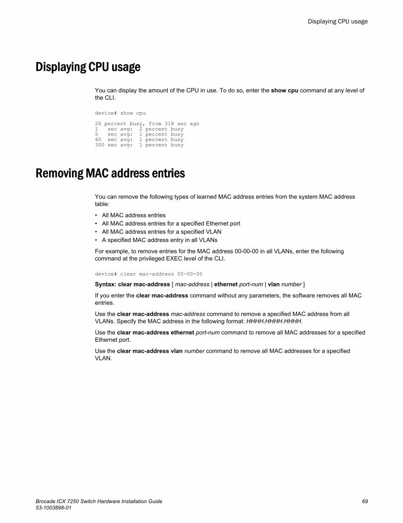
Displaying CPU usage
You can display the amount of the CPU in use. To do so, enter the show cpu command at any level ofthe CLI.
device# show cpu20 percent busy, from 318 sec ago1 sec avg: 2 percent busy5 sec avg: 1 percent busy60 sec avg: 1 percent busy300 sec avg: 1 percent busy
Removing MAC address entries
You can remove the following types of learned MAC address entries from the system MAC addresstable:
• All MAC address entries• All MAC address entries for a specified Ethernet port• All MAC address entries for a specified VLAN• A specified MAC address entry in all VLANs
For example, to remove entries for the MAC address 00-00-00 in all VLANs, enter the followingcommand at the privileged EXEC level of the CLI.
device# clear mac-address 00-00-00Syntax: clear mac-address [ mac-address | ethernet port-num | vlan number ]
If you enter the clear mac-address command without any parameters, the software removes all MACentries.
Use the clear mac-address mac-address command to remove a specified MAC address from allVLANs. Specify the MAC address in the following format: HHHH.HHHH.HHHH.
Use the clear mac-address ethernet port-num command to remove all MAC addresses for a specifiedEthernet port.
Use the clear mac-address vlan number command to remove all MAC addresses for a specifiedVLAN.
Displaying CPU usage
Brocade ICX 7250 Switch Hardware Installation Guide 6953-1003898-01

Removing MAC address entries
70 Brocade ICX 7250 Switch Hardware Installation Guide53-1003898-01
Hardware Maintenance Schedule
● Pre-connection cleaning recommendations.................................................................... 71● Copper or fiber-optic module replacement......................................................................71● Cabling a fiber-optic transceiver......................................................................................74
DANGERThe procedures in this manual are for qualified service personnel.
Pre-connection cleaning recommendationsTheICX 7250 devices require minimal maintenance for their hardware components. However, Brocaderecommends cleaning the fiber-optic connectors on a fiber-optic port and the connected fiber cableeach time you disconnect or reconnect the cable as shown in Cleaning the fiber-optic connectors onpage 74.
Copper or fiber-optic module replacementYou can replace the copper and fiber-optic modules (SFP and SFP+ transceivers). You can remove anSFP or an SFP+ transceiver from a slot and replace it with a new one while the ICX 7250 device ispowered on and running.
Removing a copper or fiber-optic moduleYou can remove a copper or fiber SFP or SFP+ transceiver from a slot while the ICX 7250 device ispowered on and running.
While removing a copper or fiber-optic module, be sure to wear an ESD wrist strap with a plug that canbe inserted in the ESD connector on the ICX 7250 device.
DANGERFor safety reasons, the ESD wrist strap should contain a series 1 megaohm resistor.
To remove a copper or fiber-optic module from an SFP or SFP+ slot, complete the following steps.
1. Put on the ESD wrist strap and ground yourself by attaching the clip end to a metal surface (such asan equipment rack).
2. Disconnect the copper or fiber cable connector from the port connector.3. Unlock the copper or fiber-optic module by pulling the bail latch forward, away from the front panel of
the module. This unlocks the module from the front panel.
Brocade ICX 7250 Switch Hardware Installation Guide 7153-1003898-01
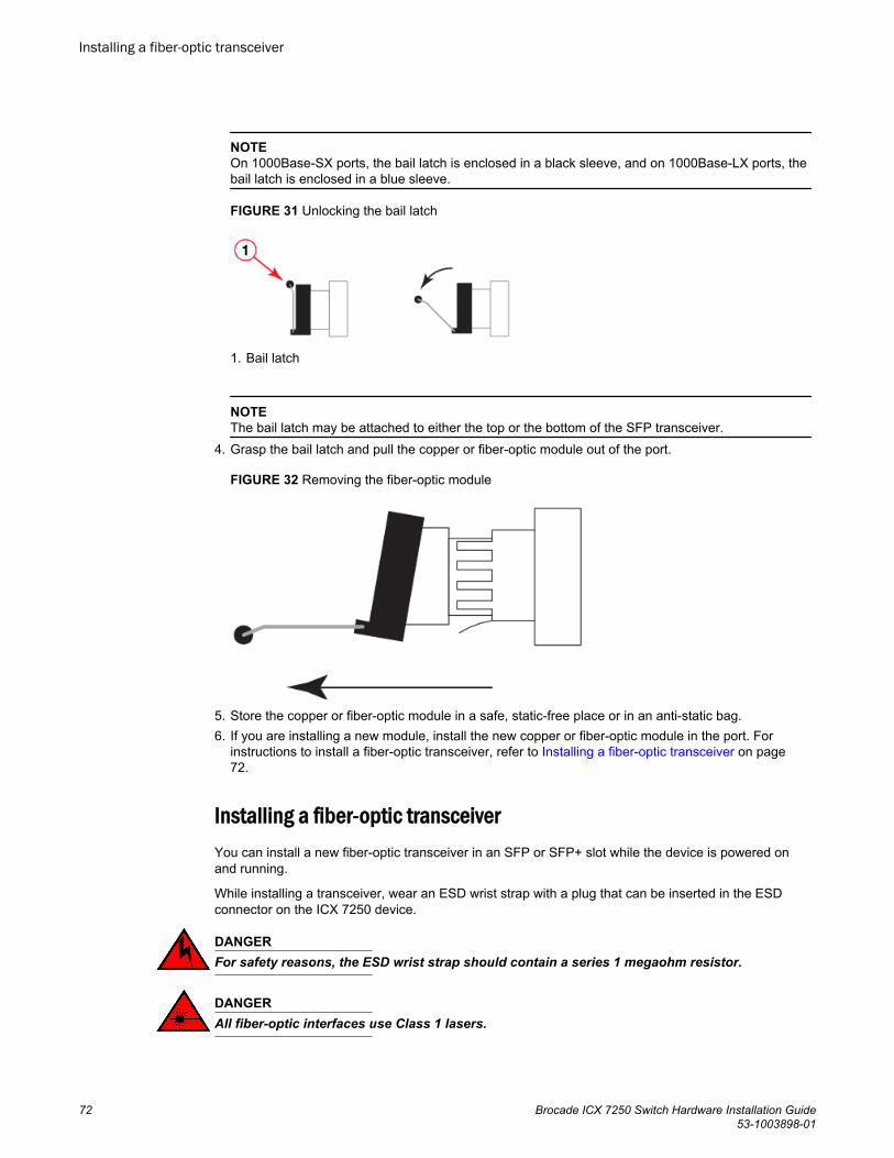
NOTEOn 1000Base-SX ports, the bail latch is enclosed in a black sleeve, and on 1000Base-LX ports, thebail latch is enclosed in a blue sleeve.
FIGURE 31 Unlocking the bail latch
1. Bail latch
NOTEThe bail latch may be attached to either the top or the bottom of the SFP transceiver.
4. Grasp the bail latch and pull the copper or fiber-optic module out of the port.
FIGURE 32 Removing the fiber-optic module
5. Store the copper or fiber-optic module in a safe, static-free place or in an anti-static bag.6. If you are installing a new module, install the new copper or fiber-optic module in the port. For
instructions to install a fiber-optic transceiver, refer to Installing a fiber-optic transceiver on page72.
Installing a fiber-optic transceiverYou can install a new fiber-optic transceiver in an SFP or SFP+ slot while the device is powered onand running.
While installing a transceiver, wear an ESD wrist strap with a plug that can be inserted in the ESDconnector on the ICX 7250 device.
DANGERFor safety reasons, the ESD wrist strap should contain a series 1 megaohm resistor.
DANGERAll fiber-optic interfaces use Class 1 lasers.
Installing a fiber-optic transceiver
72 Brocade ICX 7250 Switch Hardware Installation Guide53-1003898-01
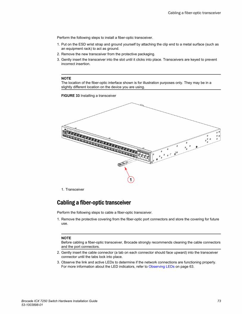
Perform the following steps to install a fiber-optic transceiver.
1. Put on the ESD wrist strap and ground yourself by attaching the clip end to a metal surface (such asan equipment rack) to act as ground.
2. Remove the new transceiver from the protective packaging.3. Gently insert the transceiver into the slot until it clicks into place. Transceivers are keyed to prevent
incorrect insertion.
NOTEThe location of the fiber-optic interface shown is for illustration purposes only. They may be in aslightly different location on the device you are using.
FIGURE 33 Installing a transceiver
1. Transceiver
Cabling a fiber-optic transceiverPerform the following steps to cable a fiber-optic transceiver.
1. Remove the protective covering from the fiber-optic port connectors and store the covering for futureuse.
NOTEBefore cabling a fiber-optic transceiver, Brocade strongly recommends cleaning the cable connectorsand the port connectors.
2. Gently insert the cable connector (a tab on each connector should face upward) into the transceiverconnector until the tabs lock into place.
3. Observe the link and active LEDs to determine if the network connections are functioning properly.For more information about the LED indicators, refer to Observing LEDs on page 63.
Cabling a fiber-optic transceiver
Brocade ICX 7250 Switch Hardware Installation Guide 7353-1003898-01
Cleaning the fiber-optic connectorsTo avoid problems with the connection between the fiber-optic transceiver (SFP or SFP+) and the fibercable connectors, Brocade strongly recommends cleaning both connectors each time you disconnectand reconnect them. Dust can accumulate in the connectors and cause problems, such as reducingthe optic launch power.
To clean the fiber cable connectors, Brocade recommends using a fiber-optic reel-type cleaner. Whennot using an SFP or SFP+ connector, make sure to keep the protective covering in place.
Cabling a fiber-optic transceiver
Perform the following steps to cable a fiber-optic transceiver.
1. Remove the protective covering from the fiber-optic port connectors and store the covering forfuture use.
NOTEBefore cabling a fiber-optic transceiver, Brocade strongly recommends cleaning the cableconnectors and the port connectors.
2. Gently insert the cable connector (a tab on each connector should face upward) into the transceiverconnector until the tabs lock into place.
3. Observe the link and active LEDs to determine if the network connections are functioning properly.For more information about the LED indicators, refer to Observing LEDs on page 63.
Cleaning the fiber-optic connectors
74 Brocade ICX 7250 Switch Hardware Installation Guide53-1003898-01
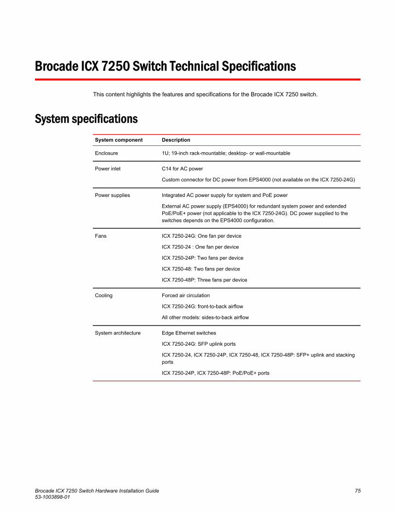
Brocade ICX 7250 Switch Technical Specifications
This content highlights the features and specifications for the Brocade ICX 7250 switch.
System specificationsSystem component Description
Enclosure 1U; 19-inch rack-mountable; desktop- or wall-mountable
Power inlet C14 for AC power
Custom connector for DC power from EPS4000 (not available on the ICX 7250-24G)
Power supplies Integrated AC power supply for system and PoE power
External AC power supply (EPS4000) for redundant system power and extendedPoE/PoE+ power (not applicable to the ICX 7250-24G). DC power supplied to theswitches depends on the EPS4000 configuration.
Fans ICX 7250-24G: One fan per device
ICX 7250-24 : One fan per device
ICX 7250-24P: Two fans per device
ICX 7250-48: Two fans per device
ICX 7250-48P: Three fans per device
Cooling Forced air circulation
ICX 7250-24G: front-to-back airflow
All other models: sides-to-back airflow
System architecture Edge Ethernet switches
ICX 7250-24G: SFP uplink ports
ICX 7250-24, ICX 7250-24P, ICX 7250-48, ICX 7250-48P: SFP+ uplink and stackingports
ICX 7250-24P, ICX 7250-48P: PoE/PoE+ ports
Brocade ICX 7250 Switch Hardware Installation Guide 7553-1003898-01
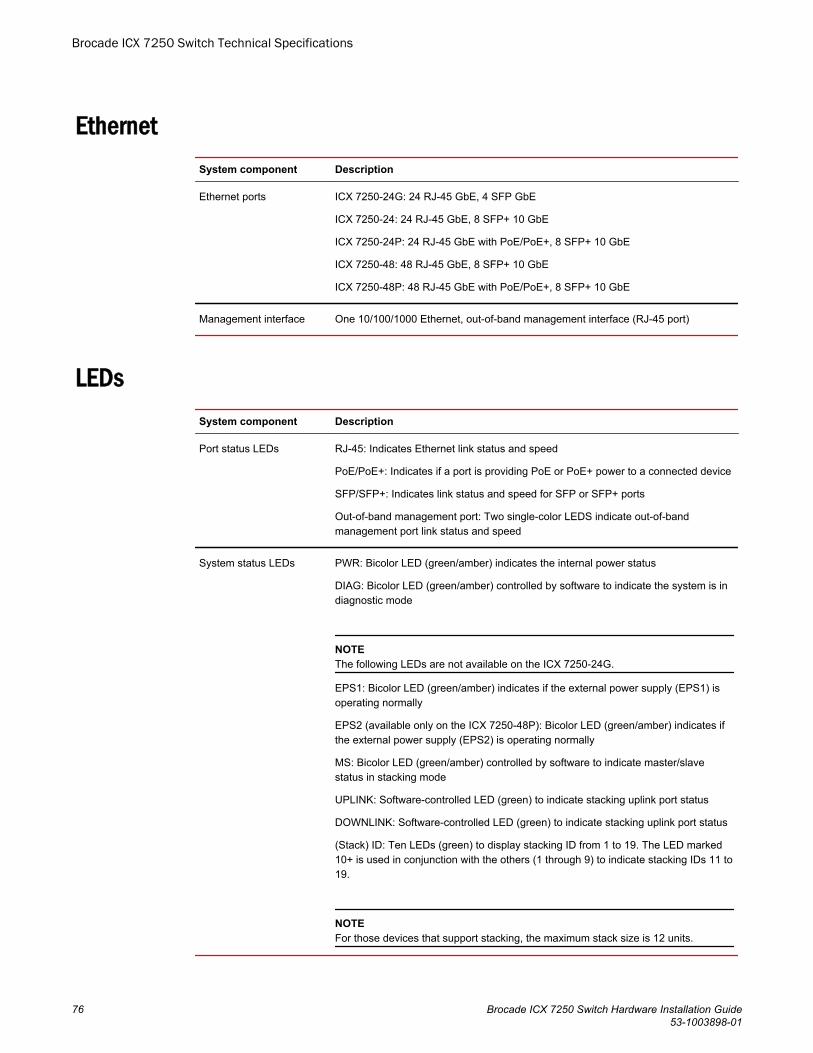
EthernetSystem component Description
Ethernet ports ICX 7250-24G: 24 RJ-45 GbE, 4 SFP GbE
ICX 7250-24: 24 RJ-45 GbE, 8 SFP+ 10 GbE
ICX 7250-24P: 24 RJ-45 GbE with PoE/PoE+, 8 SFP+ 10 GbE
ICX 7250-48: 48 RJ-45 GbE, 8 SFP+ 10 GbE
ICX 7250-48P: 48 RJ-45 GbE with PoE/PoE+, 8 SFP+ 10 GbE
Management interface One 10/100/1000 Ethernet, out-of-band management interface (RJ-45 port)
LEDsSystem component Description
Port status LEDs RJ-45: Indicates Ethernet link status and speed
PoE/PoE+: Indicates if a port is providing PoE or PoE+ power to a connected device
SFP/SFP+: Indicates link status and speed for SFP or SFP+ ports
Out-of-band management port: Two single-color LEDS indicate out-of-bandmanagement port link status and speed
System status LEDs PWR: Bicolor LED (green/amber) indicates the internal power status
DIAG: Bicolor LED (green/amber) controlled by software to indicate the system is indiagnostic mode
NOTEThe following LEDs are not available on the ICX 7250-24G.
EPS1: Bicolor LED (green/amber) indicates if the external power supply (EPS1) isoperating normally
EPS2 (available only on the ICX 7250-48P): Bicolor LED (green/amber) indicates ifthe external power supply (EPS2) is operating normally
MS: Bicolor LED (green/amber) controlled by software to indicate master/slavestatus in stacking mode
UPLINK: Software-controlled LED (green) to indicate stacking uplink port status
DOWNLINK: Software-controlled LED (green) to indicate stacking uplink port status
(Stack) ID: Ten LEDs (green) to display stacking ID from 1 to 19. The LED marked10+ is used in conjunction with the others (1 through 9) to indicate stacking IDs 11 to19.
NOTEFor those devices that support stacking, the maximum stack size is 12 units.
Brocade ICX 7250 Switch Technical Specifications
76 Brocade ICX 7250 Switch Hardware Installation Guide53-1003898-01

OtherSystem component Description
RESET Reset button for hardware reset without power cycling. There is a hole in the frontpanel to allow access.
Mini-USB port Console port for serial access to the device for management
USB port Standard type-A USB connector for removable media
Serial cable Mini-USB to RJ-45 console cable: BPN 50-1000122-01
RJ-45 connector 2x6 stacked RJ-45 connectors for GbE data ports
Weight and physical dimensions
Model Height Width Depth Weight
ICX 7250-24G 4.37 cm
1.72 in
44.0 cm
17.32 in
28 cm
11 in
3.6 kg
7.9 lb
ICX 7250-24 4.37 cm
1.72 in
44.0 cm
17.32 in
28 cm
11 in
3.8 kg
8.4 lb
ICX 7250-24P 4.37 cm
1.72 in
44.0 cm
17.32 in
28 cm
11 in
4.7 kg
10.3 lb
ICX 7250-48 4.37 cm
1.72 in
44.0 cm
17.32 in
37 cm
14.6 in
4.8 kg
10.6 lb
ICX 7250-48P 4.37 cm
1.72 in
44.0 cm
17.32 in
37 cm
14.6 in
5.9 kg
13.0 lb
Environmental requirementsCondition Operational Non-operational
Ambient temperature -5°C to 50°C (23°F to 122°F) -25°C to 70°C (-13°F to 158°F)
Relative humidity(non-condensing)
5% to 95% at 50°C (122°F) 5% to 95% at 70°C (158°F)
Brocade ICX 7250 Switch Technical Specifications
Brocade ICX 7250 Switch Hardware Installation Guide 7753-1003898-01

Condition Operational Non-operational
Altitude (above sealevel)
0 to 3,000 m (10,000 feet) 0 to 12,000 m (39,000 feet)
Shock 20 G, 11 ms, half-sine wave 33 G, 11 ms, half-sine wave
Vibration 1 G sine, 0.4 gms random, 5-500 Hz 2.4 G sine, 1.1 gms random, 5-500 Hz
Airflow ICX 7250-24G: 14.3 CFM (Maximum), 5.7CFM (Typical)
ICX 7250-24 : 14.0 CFM (Maximum), 5.7CFM (Typical)
ICX 7250-24P: 34.4 CFM (Maximum), 13.7CFM (Typical)
ICX 7250-48: 34.8 CFM (Maximum), 13.8CFM (Typical)
ICX 7250-48P: 45.2 CFM (Maximum), 21.4CFM (Typical)
N/A
Heat dissipation Refer to Power Consumption specificationsections
N/A
Operating noise ICX 7250-24G: 40 dBA
ICX 7250-24: 41.9 dBA
ICX 7250-24P: 44.7 dBA
ICX 7250-48: 44.5 dBA
ICX 7250-48P: 45.9 dBA
N/A
Power supply specifications (per PSU)The EPS4000 and its power supply modules (RPS17) are field-replaceable. All other Brocade ICX7250 power supply units (PSUs) are fixed and internal to the devices. All the PSUs use a C14 inletand connect to standard AC power.
NOTEThe EPS4000 must have at least one RPS17 installed to provide power to the supported Brocade ICX7250 devices.
Brocade ICX 7250 Switch Technical Specifications
78 Brocade ICX 7250 Switch Hardware Installation Guide53-1003898-01
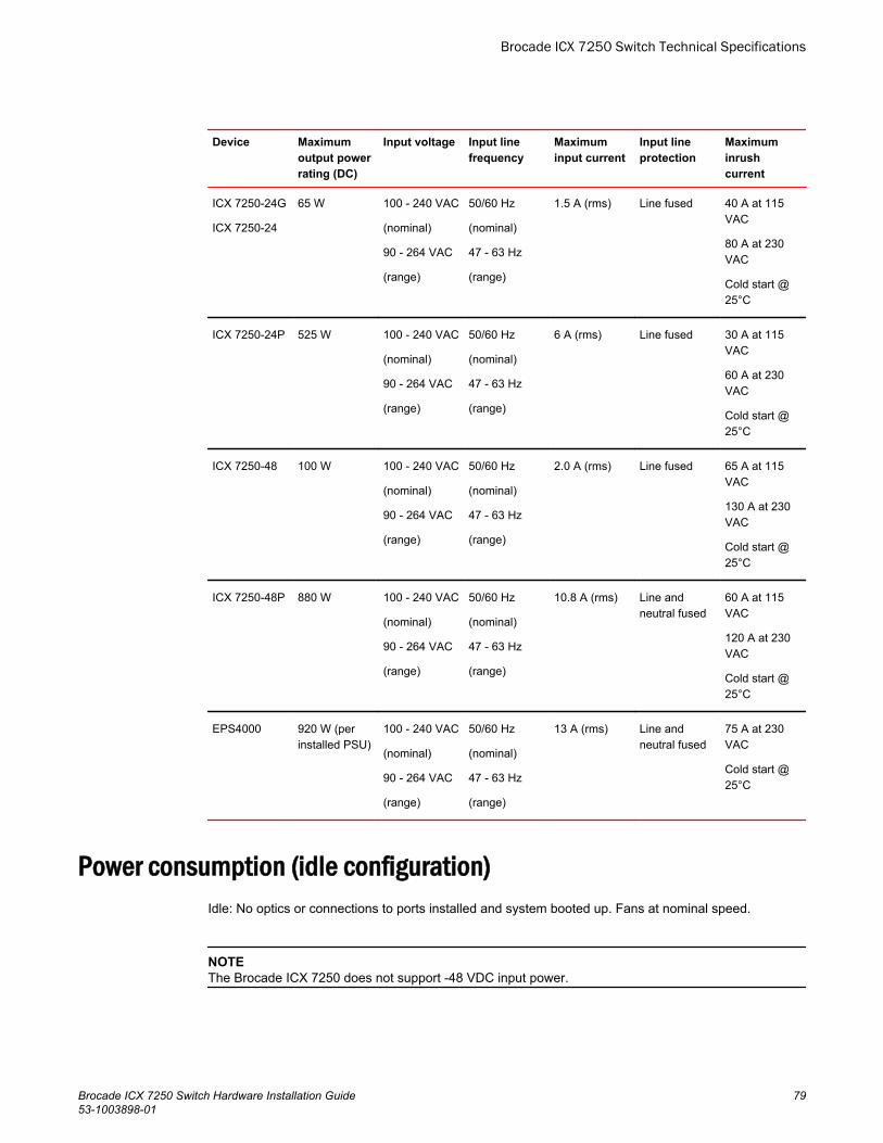
Device Maximumoutput powerrating (DC)
Input voltage Input linefrequency
Maximuminput current
Input lineprotection
Maximuminrushcurrent
ICX 7250-24G
ICX 7250-24
65 W 100 - 240 VAC
(nominal)
90 - 264 VAC
(range)
50/60 Hz
(nominal)
47 - 63 Hz
(range)
1.5 A (rms) Line fused 40 A at 115VAC
80 A at 230VAC
Cold start @25°C
ICX 7250-24P 525 W 100 - 240 VAC
(nominal)
90 - 264 VAC
(range)
50/60 Hz
(nominal)
47 - 63 Hz
(range)
6 A (rms) Line fused 30 A at 115VAC
60 A at 230VAC
Cold start @25°C
ICX 7250-48 100 W 100 - 240 VAC
(nominal)
90 - 264 VAC
(range)
50/60 Hz
(nominal)
47 - 63 Hz
(range)
2.0 A (rms) Line fused 65 A at 115VAC
130 A at 230VAC
Cold start @25°C
ICX 7250-48P 880 W 100 - 240 VAC
(nominal)
90 - 264 VAC
(range)
50/60 Hz
(nominal)
47 - 63 Hz
(range)
10.8 A (rms) Line andneutral fused
60 A at 115VAC
120 A at 230VAC
Cold start @25°C
EPS4000 920 W (perinstalled PSU)
100 - 240 VAC
(nominal)
90 - 264 VAC
(range)
50/60 Hz
(nominal)
47 - 63 Hz
(range)
13 A (rms) Line andneutral fused
75 A at 230VAC
Cold start @25°C
Power consumption (idle configuration)Idle: No optics or connections to ports installed and system booted up. Fans at nominal speed.
NOTEThe Brocade ICX 7250 does not support -48 VDC input power.
Brocade ICX 7250 Switch Technical Specifications
Brocade ICX 7250 Switch Hardware Installation Guide 7953-1003898-01
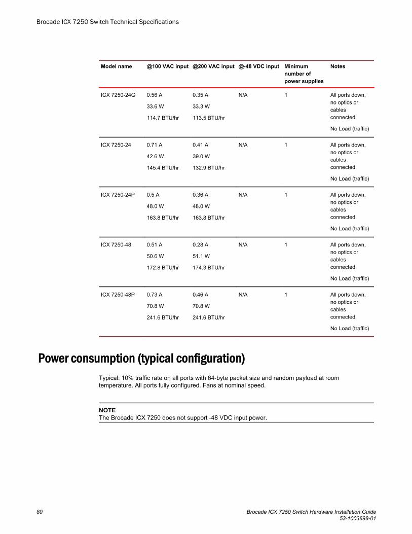
Model name @100 VAC input @200 VAC input @-48 VDC input Minimumnumber ofpower supplies
Notes
ICX 7250-24G 0.56 A
33.6 W
114.7 BTU/hr
0.35 A
33.3 W
113.5 BTU/hr
N/A 1 All ports down,no optics orcablesconnected.
No Load (traffic)
ICX 7250-24 0.71 A
42.6 W
145.4 BTU/hr
0.41 A
39.0 W
132.9 BTU/hr
N/A 1 All ports down,no optics orcablesconnected.
No Load (traffic)
ICX 7250-24P 0.5 A
48.0 W
163.8 BTU/hr
0.36 A
48.0 W
163.8 BTU/hr
N/A 1 All ports down,no optics orcablesconnected.
No Load (traffic)
ICX 7250-48 0.51 A
50.6 W
172.8 BTU/hr
0.28 A
51.1 W
174.3 BTU/hr
N/A 1 All ports down,no optics orcablesconnected.
No Load (traffic)
ICX 7250-48P 0.73 A
70.8 W
241.6 BTU/hr
0.46 A
70.8 W
241.6 BTU/hr
N/A 1 All ports down,no optics orcablesconnected.
No Load (traffic)
Power consumption (typical configuration)Typical: 10% traffic rate on all ports with 64-byte packet size and random payload at roomtemperature. All ports fully configured. Fans at nominal speed.
NOTEThe Brocade ICX 7250 does not support -48 VDC input power.
Brocade ICX 7250 Switch Technical Specifications
80 Brocade ICX 7250 Switch Hardware Installation Guide53-1003898-01
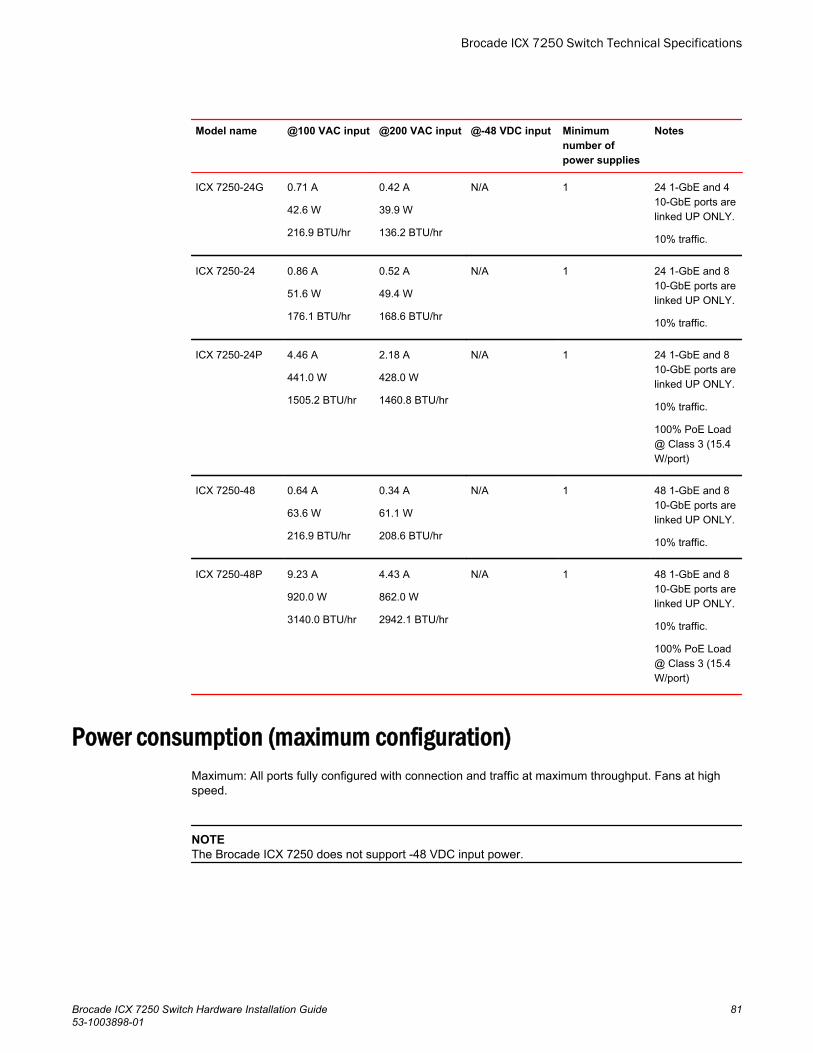
Model name @100 VAC input @200 VAC input @-48 VDC input Minimumnumber ofpower supplies
Notes
ICX 7250-24G 0.71 A
42.6 W
216.9 BTU/hr
0.42 A
39.9 W
136.2 BTU/hr
N/A 1 24 1-GbE and 410-GbE ports arelinked UP ONLY.
10% traffic.
ICX 7250-24 0.86 A
51.6 W
176.1 BTU/hr
0.52 A
49.4 W
168.6 BTU/hr
N/A 1 24 1-GbE and 810-GbE ports arelinked UP ONLY.
10% traffic.
ICX 7250-24P 4.46 A
441.0 W
1505.2 BTU/hr
2.18 A
428.0 W
1460.8 BTU/hr
N/A 1 24 1-GbE and 810-GbE ports arelinked UP ONLY.
10% traffic.
100% PoE Load@ Class 3 (15.4W/port)
ICX 7250-48 0.64 A
63.6 W
216.9 BTU/hr
0.34 A
61.1 W
208.6 BTU/hr
N/A 1 48 1-GbE and 810-GbE ports arelinked UP ONLY.
10% traffic.
ICX 7250-48P 9.23 A
920.0 W
3140.0 BTU/hr
4.43 A
862.0 W
2942.1 BTU/hr
N/A 1 48 1-GbE and 810-GbE ports arelinked UP ONLY.
10% traffic.
100% PoE Load@ Class 3 (15.4W/port)
Power consumption (maximum configuration)Maximum: All ports fully configured with connection and traffic at maximum throughput. Fans at highspeed.
NOTEThe Brocade ICX 7250 does not support -48 VDC input power.
Brocade ICX 7250 Switch Technical Specifications
Brocade ICX 7250 Switch Hardware Installation Guide 8153-1003898-01
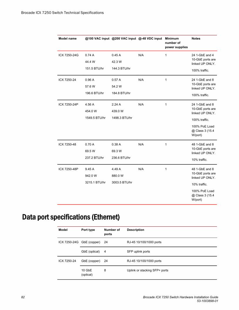
Model name @100 VAC input @200 VAC input @-48 VDC input Minimumnumber ofpower supplies
Notes
ICX 7250-24G 0.74 A
44.4 W
151.5 BTU/hr
0.45 A
42.3 W
144.3 BTU/hr
N/A 1 24 1-GbE and 410-GbE ports arelinked UP ONLY.
100% traffic.
ICX 7250-24 0.96 A
57.6 W
196.6 BTU/hr
0.57 A
54.2 W
184.8 BTU/hr
N/A 1 24 1-GbE and 810-GbE ports arelinked UP ONLY.
100% traffic.
ICX 7250-24P 4.56 A
454.0 W
1549.5 BTU/hr
2.24 A
439.0 W
1498.3 BTU/hr
N/A 1 24 1-GbE and 810-GbE ports arelinked UP ONLY.
100% traffic.
100% PoE Load@ Class 3 (15.4W/port)
ICX 7250-48 0.70 A
69.5 W
237.2 BTU/hr
0.38 A
69.3 W
236.6 BTU/hr
N/A 1 48 1-GbE and 810-GbE ports arelinked UP ONLY.
10% traffic.
ICX 7250-48P 9.45 A
942.0 W
3215.1 BTU/hr
4.49 A
880.0 W
3003.5 BTU/hr
N/A 1 48 1-GbE and 810-GbE ports arelinked UP ONLY.
10% traffic.
100% PoE Load@ Class 3 (15.4W/port)
Data port specifications (Ethernet)Model Port type Number of
portsDescription
ICX 7250-24G GbE (copper) 24 RJ-45 10/100/1000 ports
GbE (optical) 4 SFP uplink ports
ICX 7250-24 GbE (copper) 24 RJ-45 10/100/1000 ports
10 GbE(optical)
8 Uplink or stacking SFP+ ports
Brocade ICX 7250 Switch Technical Specifications
82 Brocade ICX 7250 Switch Hardware Installation Guide53-1003898-01
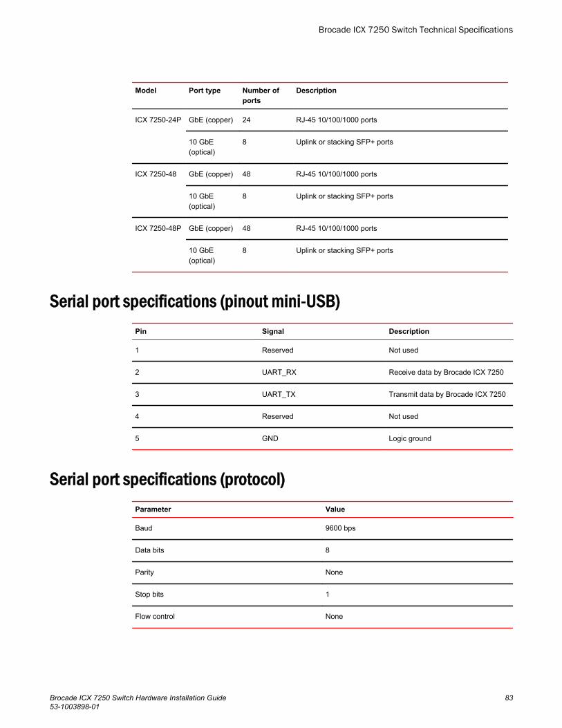
Model Port type Number ofports
Description
ICX 7250-24P GbE (copper) 24 RJ-45 10/100/1000 ports
10 GbE(optical)
8 Uplink or stacking SFP+ ports
ICX 7250-48 GbE (copper) 48 RJ-45 10/100/1000 ports
10 GbE(optical)
8 Uplink or stacking SFP+ ports
ICX 7250-48P GbE (copper) 48 RJ-45 10/100/1000 ports
10 GbE(optical)
8 Uplink or stacking SFP+ ports
Serial port specifications (pinout mini-USB)Pin Signal Description
1 Reserved Not used
2 UART_RX Receive data by Brocade ICX 7250
3 UART_TX Transmit data by Brocade ICX 7250
4 Reserved Not used
5 GND Logic ground
Serial port specifications (protocol)Parameter Value
Baud 9600 bps
Data bits 8
Parity None
Stop bits 1
Flow control None
Brocade ICX 7250 Switch Technical Specifications
Brocade ICX 7250 Switch Hardware Installation Guide 8353-1003898-01

Memory specificationsMemory Type Size
Boot SPI Flash 2 x 8 MB
Compact Flash NAND 2 GB
Main DDR3 (onboard IC) ICX 7250-24G: 1 GB
ICX 7250-24: 2 GB
ICX 7250-24P: 2 GB
ICX 7250-48: 2 GB
ICX 7250-48P: 2 GB
Regulatory compliance (EMC)• FCC Part 15, Subpart B (Class A)• EN 55022 (CE mark) (Class A)• EN 55024 (CE mark) (Immunity) for Information Technology Equipment• ICES-003 (Canada) (Class A)• AS/NZ 55022 (Australia) (Class A)• VCCI (Japan) (Class A)• EN 61000-3-2• EN 61000-3-3• EN 61000-6-1
Regulatory compliance (safety)• CAN/CSA-C22.2 No. 60950-1-07/UL60950-1 - Safety of Information Technology Equipment• EN 60825-1 Safety of Laser Products - Part 1: Equipment Classification, Requirements and User's
Guide• EN 60825-2 Safety of Laser Products - Part 2: Safety of Optical Fibre Communications Systems• EN 60950-1, IEC 60950-1 Safety of Information Technology Equipment
Regulatory compliance (environmental)• 2011/65/EU - Restriction of the use of certain hazardous substance in electrical and electronic
equipment (EU RoHS)• 2012/19/EU - Waste electrical and electronic equipment (EU WEEE)• 94/62/EC - packaging and packaging waste (EU)• 2006/66/EC - batteries and accumulators and waste batteries and accumulators (EU battery
directive)• 1907/2006 of the European Parliament and of the Council of 18 December 2006 concerning the
Registration, Evaluation, Authorisation and Restriction of Chemicals (EU REACH)
Brocade ICX 7250 Switch Technical Specifications
84 Brocade ICX 7250 Switch Hardware Installation Guide53-1003898-01

• Section 1502 of the Dodd-Frank Wall Street Reform and Consumer Protection Act of 2010 - U.S.Conflict Minerals
• 30/2011/TT-BCT - Vietnam circular• SJ/T 11363-2006 Requirements for Concentration Limits for Certain Hazardous Substances in EIPs
(China)• SJ/T 11364-2006 Marking for the Control of Pollution Caused by EIPs (China)
Brocade ICX 7250 Switch Technical Specifications
Brocade ICX 7250 Switch Hardware Installation Guide 8553-1003898-01

Brocade ICX 7250 Switch Technical Specifications
86 Brocade ICX 7250 Switch Hardware Installation Guide53-1003898-01
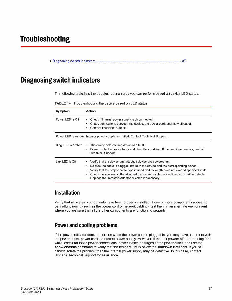
Troubleshooting
● Diagnosing switch indicators...........................................................................................87
Diagnosing switch indicatorsThe following table lists the troubleshooting steps you can perform based on device LED status.
Troubleshooting the device based on LED status TABLE 14
Symptom Action
Power LED is Off • Check if internal power supply is disconnected.• Check connections between the device, the power cord, and the wall outlet.• Contact Technical Support.
Power LED is Amber Internal power supply has failed. Contact Technical Support.
Diag LED is Amber • The device self test has detected a fault.• Power cycle the device to try and clear the condition. If the condition persists, contact
Technical Support.
Link LED is Off • Verify that the device and attached device are powered on.• Be sure the cable is plugged into both the device and the corresponding device.• Verify that the proper cable type is used and its length does not exceed specified limits.• Check the adapter on the attached device and cable connections for possible defects.
Replace the defective adapter or cable if necessary.
InstallationVerify that all system components have been properly installed. If one or more components appear tobe malfunctioning (such as the power cord or network cabling), test them in an alternate environmentwhere you are sure that all the other components are functioning properly.
Power and cooling problemsIf the power indicator does not turn on when the power cord is plugged in, you may have a problem withthe power outlet, power cord, or internal power supply. However, if the unit powers off after running for awhile, check for loose power connections, power losses or surges at the power outlet, and use theshow chassis command to verify that the temperature is below the shutdown threshold. If you stillcannot isolate the problem, then the internal power supply may be defective. In this case, contactBrocade Technical Support for assistance.
Brocade ICX 7250 Switch Hardware Installation Guide 8753-1003898-01

In-band accessYou can access the management agent in the device from anywhere within the attached networkusing Telnet or other network management software. However, you must first configure the devicewith a valid IP address, subnet mask, and default gateway. If you have trouble establishing a link tothe management agent, check to see if you have a valid network connection. Then verify that youentered the correct IP address. Also, be sure the port through which you are connecting to the devicehas not been disabled. If it has not been disabled, then check the network cabling that runs betweenyour remote location and the device.
In-band access
88 Brocade ICX 7250 Switch Hardware Installation Guide53-1003898-01
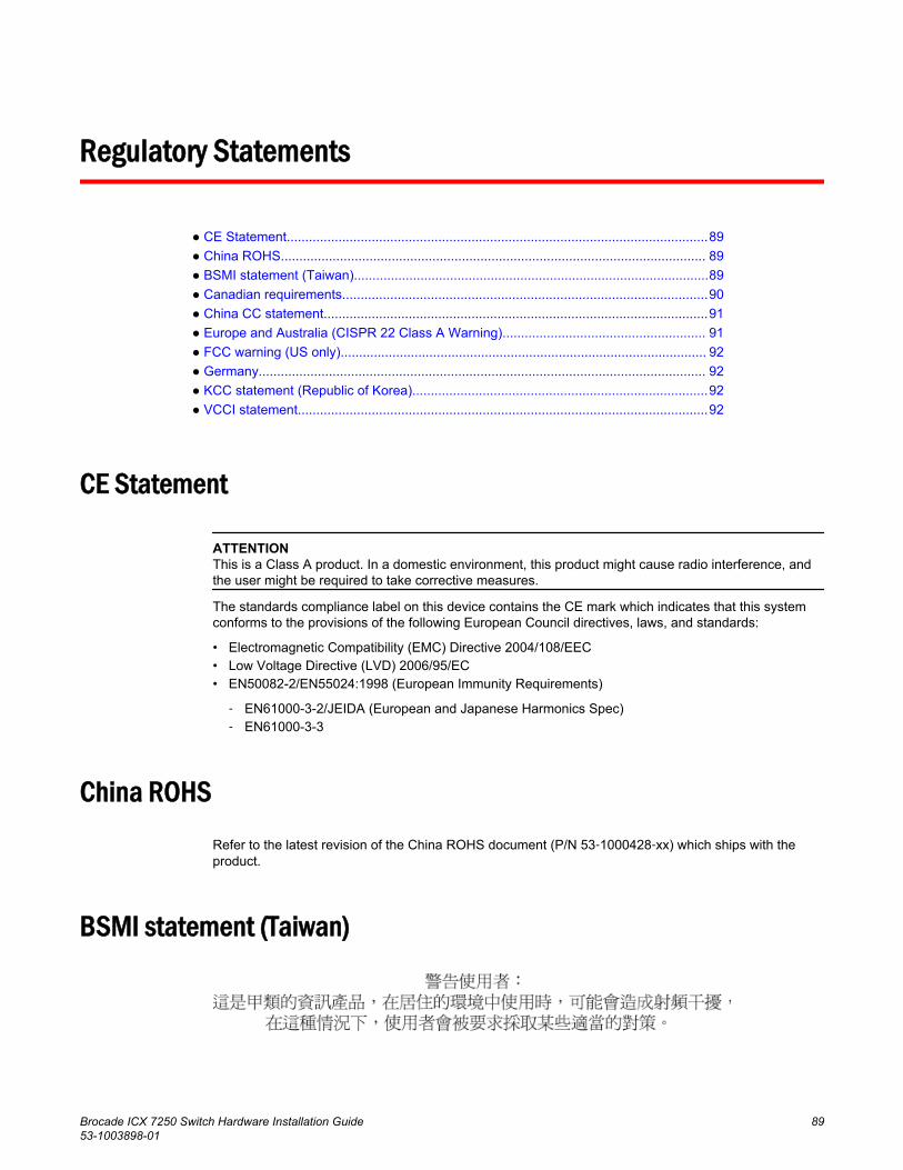
Regulatory Statements
● CE Statement..................................................................................................................89● China ROHS................................................................................................................... 89● BSMI statement (Taiwan)................................................................................................89● Canadian requirements...................................................................................................90● China CC statement........................................................................................................91● Europe and Australia (CISPR 22 Class A Warning)....................................................... 91● FCC warning (US only)................................................................................................... 92● Germany......................................................................................................................... 92● KCC statement (Republic of Korea)................................................................................92● VCCI statement...............................................................................................................92
CE Statement
ATTENTIONThis is a Class A product. In a domestic environment, this product might cause radio interference, andthe user might be required to take corrective measures.
The standards compliance label on this device contains the CE mark which indicates that this systemconforms to the provisions of the following European Council directives, laws, and standards:
• Electromagnetic Compatibility (EMC) Directive 2004/108/EEC• Low Voltage Directive (LVD) 2006/95/EC• EN50082-2/EN55024:1998 (European Immunity Requirements)
‐ EN61000-3-2/JEIDA (European and Japanese Harmonics Spec)‐ EN61000-3-3
China ROHS
Refer to the latest revision of the China ROHS document (P/N 53‐1000428‐xx) which ships with theproduct.
BSMI statement (Taiwan)
Brocade ICX 7250 Switch Hardware Installation Guide 8953-1003898-01

Warning:
This is Class A product. In a domestic environment this product may cause radio interference in whichcase the user may be required to take adequate measures.
Canadian requirementsThis Class A digital apparatus meets all requirements of the Canadian Interference-CausingEquipment Regulations, ICES-003 Class A.
Cet appareil numérique de la classe A est conforme à la norme NMB-003 du Canada.
Canadian requirements
90 Brocade ICX 7250 Switch Hardware Installation Guide53-1003898-01

China CC statement
Europe and Australia (CISPR 22 Class A Warning)This is a Class A product. In a domestic environment this product may cause radio interference in whichcase the user may be required to take adequate measures.
China CC statement
Brocade ICX 7250 Switch Hardware Installation Guide 9153-1003898-01

FCC warning (US only)This equipment has been tested and complies with the limits for a Class A computing device pursuantto Part 15 of the FCC Rules. These limits are designed to provide reasonable protection againstharmful interference when the equipment is operated in a commercial environment.
This equipment generates, uses, and can radiate radio frequency energy, and if not installed and usedin accordance with the instruction manual, might cause harmful interference to radio communications.Operation of this equipment in a residential area is likely to cause harmful interference, in which casethe user will be required to correct the interference at the user’s own expense.
GermanyMachine noise information regulation - 3. GPSGV, the highest sound pressure level value is 70.0dB(A) in accordance with EN ISO 7779.
Maschinenlärminformations-Verordnung - 3. GPSGV, der höchste Schalldruckpegel beträgt 70.0dB(A) gemäss EN ISO 7779.
KCC statement (Republic of Korea)
Class A device (Broadcasting Communication Device for Office Use): This device obtained EMCregistration for office use (Class A), and may be used in places other than home. Sellers and/or usersneed to take note of this.
VCCI statement
This is a Class A product based on the standard of the Voluntary Control Council for Interference byInformation Technology Equipment (VCCI). If this equipment is used in a domestic environment, radiodisturbance might arise. When such trouble occurs, the user might be required to take correctiveactions.
FCC warning (US only)
92 Brocade ICX 7250 Switch Hardware Installation Guide53-1003898-01
Cautions and Danger Notices
● Cautions.......................................................................................................................... 93● Danger Notices............................................................................................................... 96
Cautions
A Caution statement alerts you to situations that can be potentially hazardous to you or cause damageto hardware, firmware, software, or data.
Ein Vorsichthinweis warnt Sie vor potenziellen Personengefahren oder Beschädigung der Hardware,Firmware, Software oder auch vor einem möglichen Datenverlust
Un message de mise en garde vous alerte sur des situations pouvant présenter un risque potentiel dedommages corporels ou de dommages matériels, logiciels ou de perte de données.
Un mensaje de precaución le alerta de situaciones que pueden resultar peligrosas para usted o causardaños en el hardware, el firmware, el software o los datos.
General cautionsCAUTIONDo not install the device in an environment where the operating ambient temperature mightexceed 50°C (122°F).
VORSICHT Das Gerät darf nicht in einer Umgebung mit einer Umgebungsbetriebstemperatur von über50°C (122°F) installiert werden.
MISE ENGARDE
N'installez pas le dispositif dans un environnement où la température d'exploitation ambianterisque de dépasser 50°C (122°F).
PRECAUCIÓN No instale el instrumento en un entorno en el que la temperatura ambiente de operación puedaexceder los 50°C (122°F).
CAUTIONMake sure the airflow around the front, sides, and back of the device is not restricted.
VORSICHT Stellen Sie sicher, dass an der Vorderseite, den Seiten und an der Rückseite der Luftstromnicht behindert wird.
MISE ENGARDE
Vérifiez que rien ne restreint la circulation d'air devant, derrière et sur les côtés du dispositif etqu'elle peut se faire librement.
Brocade ICX 7250 Switch Hardware Installation Guide 9353-1003898-01
PRECAUCIÓN Asegúrese de que el flujo de aire en las inmediaciones de las partes anterior, laterales yposterior del instrumento no esté restringido.
CAUTIONEnsure that adequate ventilation is provided for the system. A 3 cm clearance is recommendedabove the device and 8 cm clearance is recommended on each side.
VORSICHT Stellen Sie sicher, dass das System ausreichend belüftet wird. Über dem Gerät wird 3 cmFreiraum, auf beiden Seiten jeweils 8 cm Freiraum empfohlen.
MISE ENGARDE
Assurez-vous que le circuit est correctement ventilé. Il est recommandé de conserver unespace de 3 cm au-dessus du dispositif, et de 8 cm sur chaque côté.
PRECAUCIÓN Asegúrese de proporcionar una ventilación adecuada al sistema. Se recomienda dejar 3 cmde espacio libre por encima del dispositivo y 8 cm a cada lado.
CAUTIONDisassembling any part of the power supply and fan assembly voids the warranty andregulatory certifications. There are no user-serviceable parts inside the power supply and fanassembly.
VORSICHT Das Zerlegen von Netzteilen oder Lüftereinheiten macht die Garantie und die gesetzlichenZertifizierungen ungültig. Die Netzteile und Lüftereinheiten enthalten keine Teile, die vomBenutzer gewartet werden können.
MISE ENGARDE
Le démontage d'une pièce du bloc d'alimentation ou du ventilateur annule la garantie et lescertificats de conformité. Aucune pièce du bloc de l'alimentation ou du ventilateur ne peut êtreréparée par l'utilisateur.
PRECAUCIÓN Si se desmonta cualquier pieza del módulo de fuente de alimentación y ventiladores, lagarantía y las certificaciones normativas quedan anuladas. En el interior del módulo de fuentede alimentación y ventiladores no hay piezas que pueda reparar el usuario.
CAUTIONUse the erase startup-config command only for new systems. If you enter this command on asystem you have already configured, the command erases the configuration. If youaccidentally do erase the configuration on a configured system, enter the write memorycommand to save the running configuration to the startup-config file.
VORSICHT Verwenden Sie den Befehl Erase startup-config (Löschen Startup-Konfig) nur für neueSysteme. Wenn Sie diesen Befehl in ein bereits konfiguriertes System eingeben, löscht derBefehl die Konfiguration. Falls Sie aus Versehen die Konfiguration eines bereits konfiguriertenSystems löschen, geben Sie den BefehlWrite Memory (Speicher schreiben) ein, um dielaufende Konfiguration in der Startup-Konfig-Datei zu speichern.
Cautions and Danger Notices
94 Brocade ICX 7250 Switch Hardware Installation Guide53-1003898-01
MISE ENGARDE
N'utilisez la commande erase startup-config que pour les nouveaux systèmes. Si vousentrez cette commande sur un système que vous avez déjà configuré, elle efface laconfiguration. Si vous effacez la configuration par accident sur un système configuré, entrez lacommande write memory pour enregistrer la configuration actuelle dans le fichier startup-config.
PRECAUCIÓN Use el comando erase startup-config (borrar configuración de inicio) para sistemas nuevossolamente. Si usted introduce este comando en un sistema que ya ha configurado, elcomando borrará la configuración. Si usted borra accidentalmente la configuración en unsistema ya configurado, introduzca el comando write memory (escribir memoria) paraguardar la configuración en ejecución en el archivo startup-config.
Electrical cautionsCAUTIONUse a separate branch circuit for each power cord, which provides redundancy in case one ofthe circuits fails.
VORSICHT Es empfiehlt sich die Installation eines separaten Stromkreiszweiges für jede Elektroschnur alsRedundanz im Fall des Ausfalls eines Stromkreises.
MISE ENGARDE
Utilisez un circuit de dérivation différent pour chaque cordon d’alimentation ainsi, il y aura uncircuit redondant en cas de panne d’un des circuits.
PRECAUCIÓN Use un circuito derivado separado para cada cordón de alimentación, con lo que seproporcionará redundancia en caso de que uno de los circuitos falle.
CAUTIONEnsure that the device does not overload the power circuits, wiring, and over-current protection.To determine the possibility of overloading the supply circuits, add the ampere (amp) ratings ofall devices installed on the same circuit as the device. Compare this total with the rating limit forthe circuit. The maximum ampere ratings are usually printed on the devices near the inputpower connectors.
VORSICHT Stromkreise, Verdrahtung und Überlastschutz dürfen nicht durch das Gerät überbelastetwerden. Addieren Sie die Nennstromleistung (in Ampere) aller Geräte, die am selbenStromkreis wie das Gerät installiert sind. Somit können Sie feststellen, ob die Gefahr einerÜberbelastung der Versorgungsstromkreise vorliegt. Vergleichen Sie diese Summe mit derNennstromgrenze des Stromkreises. Die Höchstnennströme (in Ampere) stehen normalerweiseauf der Geräterückseite neben den Eingangsstromanschlüssen.
MISE ENGARDE
Assurez-vous que le dispositif ne risque pas de surcharger les circuits d'alimentation, lecâblage et la protection de surintensité. Pour déterminer le risque de surcharge des circuitsd'alimentation, additionnez l'intensité nominale (ampères) de tous les dispositifs installés sur lemême circuit que le dispositif en question. Comparez alors ce total avec la limite de charge ducircuit. L'intensité nominale maximum en ampères est généralement imprimée sur chaquedispositif près des connecteurs d'entrée d'alimentation.
Cautions and Danger Notices
Brocade ICX 7250 Switch Hardware Installation Guide 9553-1003898-01
PRECAUCIÓN Verifique que el instrumento no sobrecargue los circuitos de corriente, el cableado y laprotección para sobrecargas. Para determinar la posibilidad de sobrecarga en los circuitos desuministros, añada las capacidades nominales de corriente (amp) de todos los instrumentosinstalados en el mismo circuito que el instrumento. Compare esta suma con el límite nominalpara el circuito. Las capacidades nominales de corriente máximas están generalmenteimpresas en los instrumentos, cerca de los conectores de corriente de entrada.
CAUTIONBefore plugging a cable into to any port, be sure to discharge the voltage stored on the cableby touching the electrical contacts to ground surface.
VORSICHT Bevor Sie ein Kabel in einen Anschluss einstecken, entladen Sie jegliche im Kabelvorhandene elektrische Spannung, indem Sie mit den elektrischen Kontakten eine geerdeteOberfläche berühren.
MISE ENGARDE
Avant de brancher un câble à un port, assurez-vous de décharger la tension du câble enreliant les contacts électriques à la terre.
PRECAUCIÓN Antes de conectar un cable en cualquier puerto, asegúrese de descargar la tensiónacumulada en el cable tocando la superficie de conexión a tierra con los contactos eléctricos.
CAUTIONDisassembling any part of the power supply and fan assembly voids the warranty andregulatory certifications. There are no user-serviceable parts inside the power supply and fanassembly.
VORSICHT Das Zerlegen von Netzteilen oder Lüftereinheiten macht die Garantie und die gesetzlichenZertifizierungen ungültig. Die Netzteile und Lüftereinheiten enthalten keine Teile, die vomBenutzer gewartet werden können.
MISE ENGARDE
Le démontage d'une pièce du bloc d'alimentation ou du ventilateur annule la garantie et lescertificats de conformité. Aucune pièce du bloc de l'alimentation ou du ventilateur ne peut êtreréparée par l'utilisateur.
PRECAUCIÓN Si se desmonta cualquier pieza del módulo de fuente de alimentación y ventiladores, lagarantía y las certificaciones normativas quedan anuladas. En el interior del módulo de fuentede alimentación y ventiladores no hay piezas que pueda reparar el usuario.
Danger Notices
A Danger statement indicates conditions or situations that can be potentially lethal or extremelyhazardous to you. Safety labels are also attached directly to products to warn of these conditions orsituations.
Ein Gefahrenhinweis warnt vor Bedingungen oder Situationen die tödlich sein können oder Sie extremgefährden können. Sicherheitsetiketten sind direkt auf den jeweiligen Produkten angebracht um vordiesen Bedingungen und Situationen zu warnen.
Danger Notices
96 Brocade ICX 7250 Switch Hardware Installation Guide53-1003898-01
Un paragraphe Danger indique des conditions ou des situations potentiellement mortelles ouextrêmement dangereuses. Des labels de sécurité sont posés directement sur le produit et vousavertissent de ces conditions ou situations
Una advertencia de peligro indica condiciones o situaciones que pueden resultar potencialmente letaleso extremadamente peligrosas. También habrá etiquetas de seguridad pegadas directamente sobre losproductos para advertir de estas condiciones o situaciones.
General dangersDANGERThe procedures in this manual are for qualified service personnel.
GEFAHR Die Vorgehensweisen in diesem Handbuch sind für qualifiziertes Servicepersonal bestimmt.
DANGER Les procédures décrites dans ce manuel doivent être effectuées par un personnel demaintenance qualifié.
PELIGRO Los procedimientos de este manual deben llevarlos a cabo técnicos cualificados.
DANGERBe careful not to accidently insert your fingers into the fan tray while removing it from thechassis. The fan may still be spinning at a high speed.
GEFAHR Die Finger dürfen nicht versehentlich in das Ventilatorblech gesteckt werden, wenn dieses vomGehäuse abgenommen wird. Der Ventilator kann sich unter Umständen noch mit hoherGeschwindigkeit drehen.
DANGER Faites attention de ne pas accidentellement insérer vos doigts dans le boîtier du ventilateurlorsque vous l'enlevez du châssis. Il est possible que le ventilateur tourne encore à grandevitesse
PELIGRO Procure no insertar los dedos accidentalmente en la bandeja del ventilador cuando estédesmontando el chasis. El ventilador podría estar girando a gran velocidad.
DANGERThis equipment is suitable for mounting on concrete or other noncombustible surfaces only.
GEFAHR Dieses Gerät darf nur auf Beton oder auf andere, nicht brennbare Flächen installiert werden.
DANGER Cet équipement est adapté à être monté sur du béton ou seulement sur d'autres surfaces noncombustibles.
PELIGRO Este equipo es apto para el montaje solamente en superficies de concreto ó en otro tipos desuperficies no combustibles.
Cautions and Danger Notices
Brocade ICX 7250 Switch Hardware Installation Guide 9753-1003898-01
Electrical dangersDANGERBefore beginning the installation, see the precautions in “Power precautions.”
GEFAHR Vor der Installation siehe Vorsichtsmaßnahmen unter “Power Precautions”(Vorsichtsmaßnahmen in Bezug auf elektrische Ablagen).
DANGER Avant de commencer l'installation, consultez les précautions décrites dans “PowerPrecautions” (Précautions quant à l'alimentation).
PELIGRO Antes de comenzar la instalación, consulte las precauciones en la sección “PowerPrecautions” (Precauciones sobre corriente).
DANGERDisconnect the power cord from all power sources to completely remove power from thedevice.
GEFAHR Ziehen Sie das Stromkabel aus allen Stromquellen, um sicherzustellen, dass dem Gerät keinStrom zugeführt wird.
DANGER Débranchez le cordon d'alimentation de toutes les sources d'alimentation pour coupercomplètement l'alimentation du dispositif.
PELIGRO Para desconectar completamente la corriente del instrumento, desconecte el cordón decorriente de todas las fuentes de corriente.
DANGERIf the installation requires a different power cord than the one supplied with the device, makesure you use a power cord displaying the mark of the safety agency that defines theregulations for power cords in your country. The mark is your assurance that the power cordcan be used safely with the device.
GEFAHR Falls für die Installation ein anderes Stromkabel erforderlich ist (wenn das mit dem Gerätgelieferte Kabel nicht passt), müssen Sie sicherstellen, dass Sie ein Stromkabel mit demSiegel einer Sicherheitsbehörde verwenden, die für die Zertifizierung von Stromkabeln inIhrem Land zuständig ist. Das Siegel ist Ihre Garantie, dass das Stromkabel sicher mit IhremGerät verwendet werden kann.
DANGER Si l'installation nécessite un cordon d'alimentation autre que celui fourni avec le dispositif,assurez-vous d'utiliser un cordon d'alimentation portant la marque de l'organisationresponsable de la sécurité qui définit les normes et régulations pour les cordons d'alimentationdans votre pays. Cette marque vous assure que vous pouvez utiliser le cordon d'alimentationavec le dispositif en toute sécurité.
Cautions and Danger Notices
98 Brocade ICX 7250 Switch Hardware Installation Guide53-1003898-01
PELIGRO Si la instalación requiere un cordón de corriente distinto al que se ha suministrado con elinstrumento, verifique que usa un cordón de corriente que venga con la marca de la agenciade seguridad que defina las regulaciones para cordones de corriente en su país. Esta marcaserá su garantía de que el cordón de corriente puede ser utilizado con seguridad con elinstrumento.
DANGERFor safety reasons, the ESD wrist strap should contain a series 1 megaohm resistor.
GEFAHR Aus Sicherheitsgründen sollte ein EGB-Armband zum Schutz von elektronischen gefährdetenBauelementen mit einem 1 Megaohm-Reihenwiderstand ausgestattet sein.
DANGER Pour des raisons de sécurité, la dragonne ESD doit contenir une résistance de série 1 mégaohm.
PELIGRO Por razones de seguridad, la correa de muñeca ESD deberá contener un resistor en serie de 1mega ohmio.
Dangers related to equipment weightDANGERMake sure the rack housing the device is adequately secured to prevent it from becomingunstable or falling over.
GEFAHR Stellen Sie sicher, dass das Gestell für die Unterbringung des Geräts auf angemessene Weisegesichert ist, so dass das Gestell oder der Schrank nicht wackeln oder umfallen kann.
DANGER Vérifiez que le bâti abritant le dispositif est bien fixé afin qu'il ne devienne pas instable ou qu'ilne risque pas de tomber.
PELIGRO Verifique que el bastidor que alberga el instrumento está asegurado correctamente para evitarque pueda hacerse inestable o que caiga.
DANGERMount the devices you install in a rack as low as possible. Place the heaviest device at thebottom and progressively place lighter devices above.
GEFAHR Montieren Sie die Geräte im Gestell so tief wie möglich. Platzieren Sie das schwerste Gerätganz unten, während leichtere Geräte je nach Gewicht (je schwerer desto tiefer) darüberuntergebracht werden.
DANGER Montez les dispositifs que vous installez dans un bâti aussi bas que possible. Placez ledispositif le plus lourd en bas et le plus léger en haut, en plaçant tous les dispositifsprogressivement de bas en haut du plus lourd au plus léger.
Cautions and Danger Notices
Brocade ICX 7250 Switch Hardware Installation Guide 9953-1003898-01
PELIGRO Monte los instrumentos que instale en un bastidor lo más bajos posible. Ponga el instrumentomás pesado en la parte inferior y los instrumentos progresivamente más livianos más arriba.
Laser dangersDANGERAll fiber-optic interfaces use Class 1 lasers.
GEFAHR Alle Glasfaser-Schnittstellen verwenden Laser der Klasse 1.
DANGER Toutes les interfaces en fibres optiques utilisent des lasers de classe 1.
PELIGRO Todas las interfaces de fibra óptica utilizan láser de clase 1.
Cautions and Danger Notices
100 Brocade ICX 7250 Switch Hardware Installation Guide53-1003898-01
Recommended