F5 Feedback UnitInstallation and Operation
Manual
1-800-899-0553assuredautomation.com

Manual F5 – 2 –
Manufacturers declaration • Hersteller-Erklärung • Déclaration de fabricant
GB
Manufacturers declarationin compliance with EC directive 89/392/EEC/91/368/EEC, 89/336/EEC, 73/23/EEC
and 93/68/EEC.We hereby confirm that the appliances described in this sheet has been manufactured in compliance
with the applicable standards and is intended for installation in a machine/application, and thatcommissioning is strictly prohibited until evidence has been provided that the machine/application in
question is also in compliance withEC directive 89/392/EEC/91/368/EEC, 89/336/EEC, 73/23/EEC and 93/68/EEC.
This manufacturers declaration is applicable to the following PMV series:F5.
D
Hersteller-Erklärungim Sinne der EG-Richtlinie 89/392/EWG/91/368/EWG, 89/336/EWG, 73/23/EWG
und 93/68/EWG.Hiermit erklären wir, daß die in diesem Blatt beschriebenen Geräte entsprechend den gültigen Normen
gebaut und zum Einbau in eine Maschine oder Applikation bestimmt sind, sowie daß derenInbetriebnahme so lange untersagt ist, bis festgestellt wurde, daß diese
Maschine/Applikation ebenfalls der EG-Richtlinie89/392/EWG/91/368/EWG, 89/336/EWG, 73/23/EWG und 93/68/EWG entspricht.
Diese Herstellererklärung hat für folgende PMV-Serien Gültigkeit:F5.
F
Déclaration de fabricantau sens dela directive de la 89/392/CEE/91/368/CEE, 89/336/CEE, 73/23/CEE et 93/68/CEE.
Nous déclarons par la présente que les appareils décrits sur cette page sont construits en conformitéavec les normes en vigueur et qu'ils sont destinés à être montés dans une machine ou une application,nous déclarons également que leur mise en service est interdite tant qu'il n'a pas été constaté que cette
macine/application satisfaitégalement à la directive 89/392/CEE/91/368/CEE, 89/336/CEE, 73/23/CEE et 93/68/CEE.
Cette déclaration de fournisseur est valable pour les types d'appareils PMV suivants:F5.
Mr. Jan-Eric AnderssonPresident, Palmstiernas Instrument AB
1-800-899-0553assuredautomation.com
Manual F5 – 3 –
PMV Feedback module storage and handling procedures
PMV feedback modules are precision instruments which should be storedand handled accordingly to avoid problems or damage.Feedback modules contain electronic components which can be damaged byexposure to water. Appropriate precautions should be taken to protect unitswhile in storage.
Warehouse storage-Stored in original PMV shipping containers, units should be stored in anenvironmentally controlled area, i.e. clean, cool (15-26°C, 60-80°F) and dry,out of direct sunlight or weather exposure.
Field storage- If feedback units must be stored outdoors, make sure front covers aretightened, all conduits entries are sealed and that units not are exposed todirect sunlight, rain or snow.
Potential damage mechanismWhen units are stored in hot, humid climates, the daily heating/cooling cyclewill cause air to expand/contract and be drawn in and out of the feedbackhousing through ports left open. Dependent on the local temperaturevariations, humidity and dew points and time in storage, condensation couldoccur and accumulate inside causing erratic operation or failure due to waterand corrosion. The potential for condensation damage is especially high insouthern climates and aggravated if units are exposed to direct sunlight.
For further assistance, please contact you nearest PMV office.
Storage SealF5 is supplied with conduit entry points sealed.The seal is only a storage seal, not to be used as sealwhen F5 is in operation.If Storage Seal is removed or damaged, make sureconduit entry points are resealed before furthershipping or storage.Use proper cable glands or vapour proof tape.
Mount F5 on positioner P5/E5 or actuator/valve package. Remove Storage Seal for conduit entry E1& E2, make electrical connections, install proper cable glands or plugs to ensure the units sealing.
1-800-899-0553assuredautomation.com

Manual F5 – 4 –
Description
The F5 is a feedback unit uniquely designed to mount on top of the P5 or E5 positioners with minimum parts required. The F5 can also be mounted on actuators with an additional mounting kit. The F5 is available in two different enclosures, standard or explosion proof.
The standard enclosure for F5 offers a gasketed NEMA 4/ IP66 enclosure withoptional American and European intrinsically safe approvals. The explosionproof version is approved NEMA 7 / IP66 and carries North American andEuropean approvals. Both enclosures can be furnished with Namur sensors,mechanical or proximity switches, potentiometer or 4-20 mA position trans-mitter or a combination of these items.
1-800-899-0553assuredautomation.com
Manual F5 – 5 –
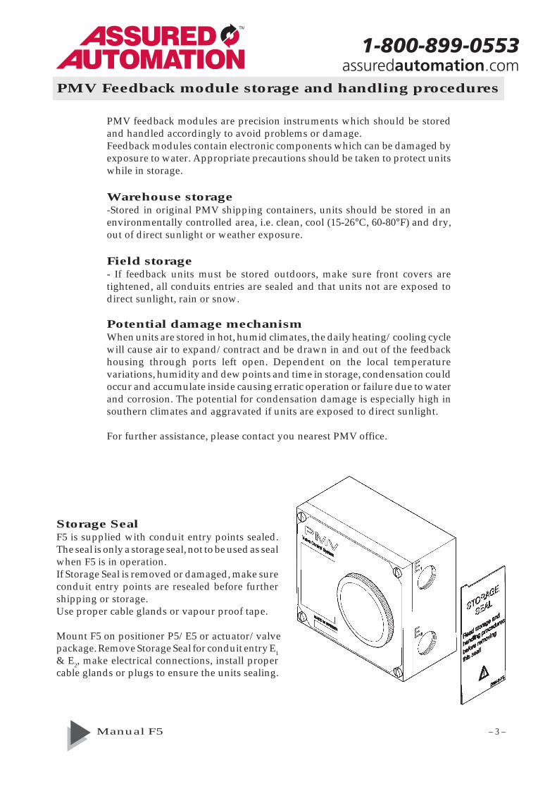
Mounting on P5 or E5
Mounting F5 on actuator (On/Off control valves)Install the spindle adaptor 1 into F5 shaft, make sure that a spring clip 2is fitted. A solid click should be heard when the spindle adaptor isproperly installed into the F5 shaft.Mount F5 on the actuator using a mounting kit and the ISO F05 mountingholes on the bottom of the F5. Make sure that the F5 spindle is properlyalligned on top of the actuator.Check that the four fasteners 3 are installed into F5.
3
12
– Remove the front cover and the indicator from the positioner.– Loosen and remove the Allen head screw (3) (5mm hex-wrench)– Install drive coupling (4) on the positioner shaft, secure it with screw (3)– Check that F5is fitted with 4 nos of screws 5 and O-ring 9, install the F5 on
top of the positioner unit, make sure that the coupling is properly engagedbefore tightening the four screws 5.
– Make connections and calibrate.– Reinstall indicator 2 and front cover 1 on the F5.
O-ring seal
9 5
24
3
5
1
1-800-899-0553assuredautomation.com

Manual F5 – 6 –
Mounting on P-2000/P-2020
6
5
3
2
1
7
– Remove front cover, indicator and cam nut from the positioner– Replace the cam nut with coupling 1, calibrate the positioner.– Check that the gasket is fitted to the bottom of plate 2, install screws 5 (3x
long, 1x short) plastic washer 6 and O-rings 7.– Secure the F5 to the plate 2 with screws 3.– Install assembly onto the positioner, make sure that coupling 1 is properly
engaged.– Make electrical connections and calibrate.
1-800-899-0553assuredautomation.com

Manual F5 – 7 –
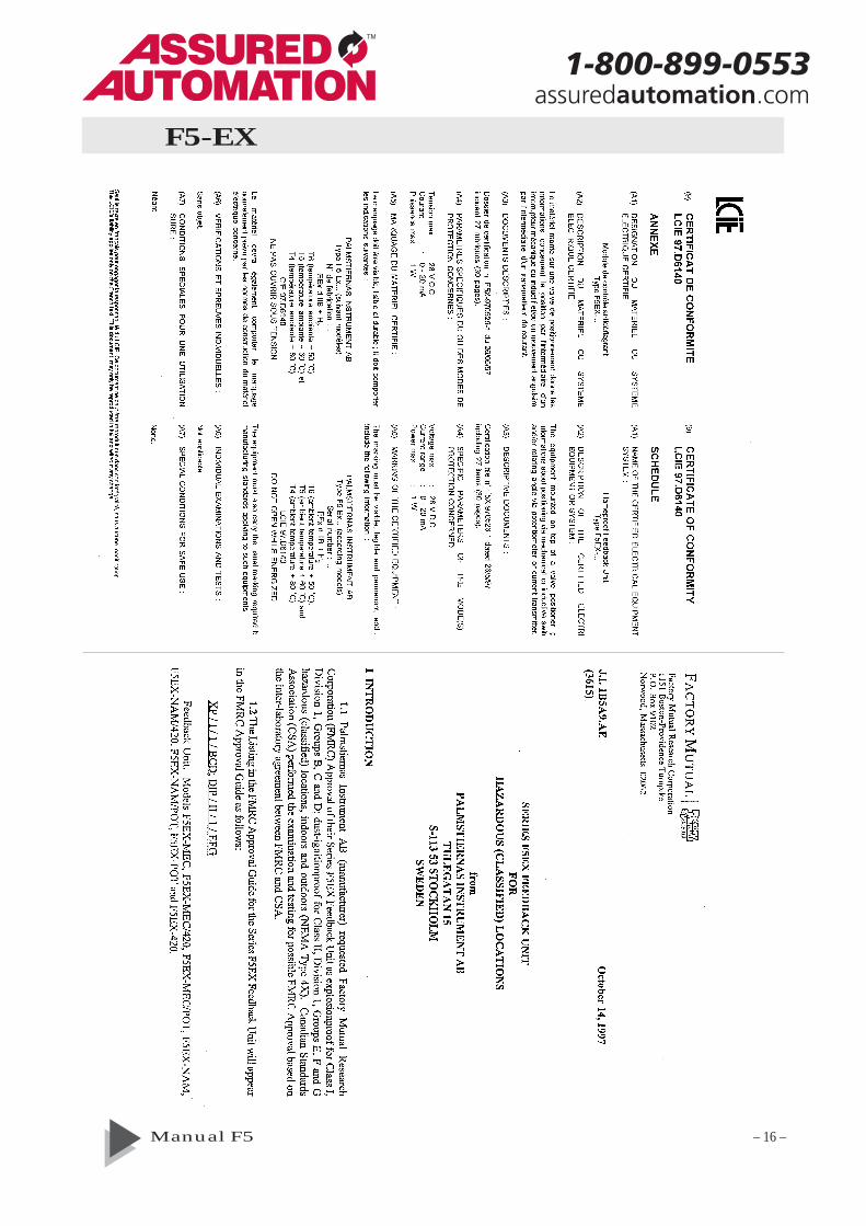
F5-EX
The F5-EX is approved explosion proof by CSA, FM and CENELEC.Front cover screws shall be tightened 7 Nm (5,2 lbf x ft).
Approvals:CSA, FM Div. 1, Class 1,2 & 3 Group BCDEFG T4-T6
CENELEC EEx d IIB + H2 T4-T6 LCIE 97.D6140
1-800-899-0553assuredautomation.com

Manual F5 – 8 –
assuredautomation.com
Installing F5-EX on P5/E5
Installing on an actuator
– Remove front cover, indicator and Allen head screw from the positioner.– Install drive coupling 4 and secure it with the Allen head screw.– Remove front covers and indicator from the F5-EX unit.–
Remove screws 3.
– Install F5-EX on P5/E5, , make sure drive coupling is properly engagedbefore tightening screws 5.
– Reinstall and tight screws 3. Connect and calibrate.– Reinstall front covers and indicator.– Front cover screws 2 shall be tightened to 7 Nm (5,2 lbf x ft)
– Remove front covers and indicator from the F5-EX unit.– Remove screws 3 and (5). Reinstall and tight screws 3.– Install drive shaft into F5-EX, a solid click should be heard when spindle
adapter is properly installed.– Mount F5-EX on the actuator using the F05 holes and a mounting kit.– Connect and calibrate, reinstall front covers and indicator.– Front cover screws 2 shall be tightened to 7 Nm (5,2 lbf x ft).
4
5 32
32
1-800-899-0553
Manual F5 – 9 –
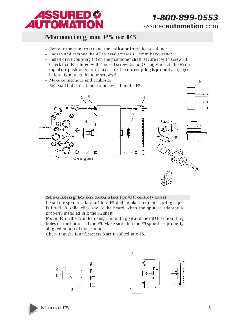
Connections
WARNING!Units installed in hazardous locations must have proper agency approvalsand be installed according to installation drawing F5-2-4-9516.
Conduit entries are PG13,5 (M20) or NPT 1/2“Make electrical connections according to wiring diagrams and tighten cableglands. Terminals are 2.5 mm2 (AVG 14) screw terminals.
Adjustments
CAUTION! Moving parts – risk of injury.The cams/gear wheel are secured in position by friction provided from thecam/shaft assembly. To adjust switches and/or position transmitter, rotategear wheel 2 and cams 3 to desired position using tool F5-22 or tip of a screwdriver that fits snuggly in one of the slotted holes. Start calibration procedureby adjusting position transmitter first, then continue with the lower switchand complete with the upper switch.If cams exhibit high stiction, rotate them back and forth rapidly several times.Do not adjust nut 4 or lubricate cams, call PMV for assistance.
1-800-899-0553assuredautomation.com

Manual F5 – 10 –
CalibrationPotentiometer1. Make electrical connections to terminals 7,8 and 9. Check that the
potentiometer is connected to connector C on the printed circuit board.2. Stroke the actuator to check direction of travel indicated by the potentio-
meter. To change direction of travel, swap wires at terminals 7 and 9.3. Stroke the actuator to the position where the minimum potentiometer
resistance is desired.4. Adjust the potentiometer output reading to approx. 50 Ohm by
rotating gear wheel 2 with special tool F5-22 or tip of a screw driverplaced in one of the slotted holes.
5. Stroke the actuator to desiredmaximum resistance position andcheck reading.
6. Repeat steps 3-5 if necessary toobtain desired resistance change.
7. Set switches or install frontcover.
Potentiometer
7
89
PowerSupply24 VDC
+
-
4-20 mA position transmitter
89
-+
Display4-20 mA
+-4-20 mApositiontransmitter
5. Adjust the output signal 4,0 mA with potentio-meter P2. LED will illuminate when out put is 4mA (±1%) or less. Stroke actuator to the desired 20mA position and adjust the output to 20,0 mA withpotentiometer P1. LED will illuminate when output is 20 mA (±1%) or more.
6. Stroke actuator again, check and adjust 4 mA and20 mA readings. Install front cover or set switchesfirst, as follows:
4-20 mA position transmitter1. Set direction of rotation by placing potentiometer jumper in location A or
B. (Location A for counter clockwise CCW valve/actuator rotation (Direct),location B for clockwise CW valve/actuator rotation (Reverse).
2. Set jumper X to the desired valve rotation angle, for 30 deg or 45 degrotation choose position 30,For 60 deg or 90 deg rotation choose position 90, for 180 deg rotation chooseposition 30 and for 270 deg rotations choose position 90.For 30° deg - 45° deg choose pos 30.
3. Make electrical connections according to wiring diagram. Power supplyshould be >9 to <28 VDC (24 VDC recommended).
4. Connect a 4-20 mA meter to testoutlet 1. Adjust potentiometer P1 20revolutions CW & P2 20 revolutions CCW. Stroke actuator to the desired 4mA position and check that current deflection is correct. Rotate gear wheel2 with tool F5-22 or tip of a screw driver placed in one of the slotted holesuntil minimum valve is reached.
1-800-899-0553assuredautomation.com

Manual F5 – 11 –
Limit switches cams must be adjusted separately with valve in an open andclosed position. With the valve in fully open or closed position adjust thelower cam 3 to desired position by rotating it with special tool F5-22 or by thetip of a screw driver placed in one of the slotted holes on the cam. Stroke thevalve fully and repeat the procedure above to set the upper cam.Stroke valve open/closed to check proper limit switch operation.
Switches & Sensors
Technical specifications
GeneralConduit entries 2x 1/2 NPT or 2x PG 13,5 (M20)Housing material Die cast aluminumSurface treatment ED paintingMounting According to VDI/VDE 3845Fasteners Stainless steel A2/A4Terminals 2,5 mm2 (AVG 14)Enclosure IP66, NEMA 4
Switches, mechanicalType Mechanical SPDT V3Rating *6/2,5A 250 VAC *Res/IndApprovals CSA,UL,VDETemp range -20°C to 80°C (-4°F to 185°F)
Sensors, NamurType Proximity DIN 19234 NAMURLoad Current ≤ 1mA ≥ 3mAVoltage range 5-25 VDCHysteresis 0,2%Temp range -20°C to 80°C (-4°F to 185°F)
PotentiometerOut put 5kΩ (4kΩ at 90°)Elements Conductive plasticPower rating at 70° 1 WLinearity 1%Resolution Essentially infiniteTemp range -20°C to 80°C (-4°F to 185°F)
4-20 mA position transmitterPower supply 9-28 VDC (24VDC recommended)Out put signal 4-20 mALED indication at 4 mA ±1%LED indication at 20 mA ±1%Resolution InfiniteMinimum rotation travel 30°Maximum rotation travel 90°Linearity <1% of full scaleHysteresis <0,5% of full scaleOut put current limit 24 mA DCLoad impedance 800 Ω at 24 VDCTemp range -20°C to 80°C (-4°F to 185°F)
NAMUR switches
23
56
Upperswitch
Lowerswitch
+-
+-
123
654
Upperswitch
Lowerswitch
C
C
Mechanical switches
NC
NC
NO
NO
123
654
Upperswitch
Lowerswitch
C
C
Mechanical switches
NC
NC
NO
NO
WeightStandard enclosure 0.7 kg (lbs 1.5)Explosion proof 2.1 kg (lbs 4.6)
Switches proximityContact rating 2 W or 2 VA @ 30 VDC/
VAC, 0.1 AMaximum operating time 0.5 milisecondsBreakdown voltage 200VDCContact resistance 0.2 OhmsSwitch type SPDT hermetically sealed
in one unitMechanical andelectrical life >10 million operations
Proximity switches Mechanical switches Namur sensors
1-800-899-0553assuredautomation.com
Manual F5 – 12 –
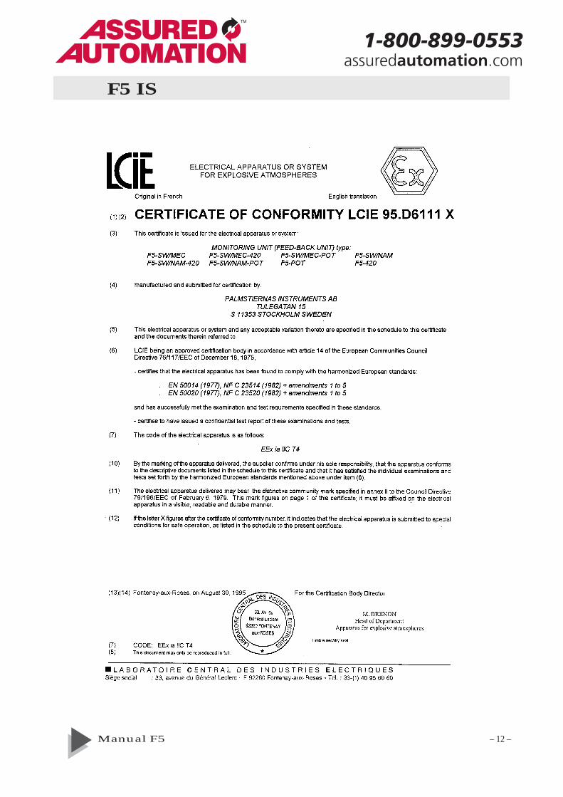
F5 IS
1-800-899-0553assuredautomation.com

Manual F5 – 13 –
F5 IS
1-800-899-0553assuredautomation.com

Manual F5 – 14 –
Connection of F5 intrinsically safe version
1-800-899-0553assuredautomation.com

Manual F5 – 15 –
F5-EX
1-800-899-0553assuredautomation.com
Manual F5 – 16 –
F5-EX
1-800-899-0553assuredautomation.com

Manual F5 – 17 –
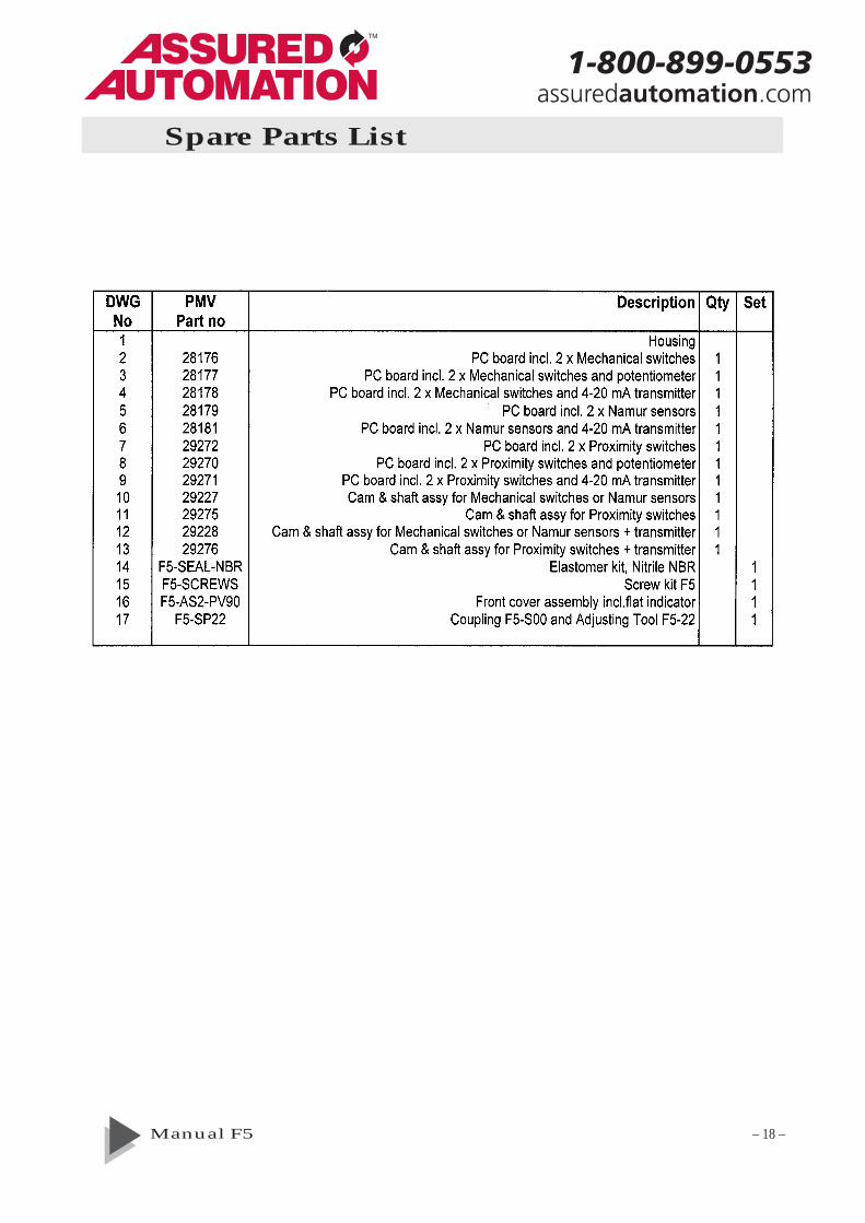
Spare Parts
10-13
10-1314
14
17
115
15
10-13
2-9
1416 16
15
14
16
16
1-800-899-0553assuredautomation.com
Manual F5 – 18 –
Spare Parts List
1-800-899-0553assuredautomation.com

Manual F5 – 19 –
Dimension drawing
1-800-899-0553assuredautomation.com
Trouble shooting
SwitchesCheck electrical connections and cam settings.
PotentiometerIf there is no output signal, check electrical connec-tions and for open circuit, check that potentio-meter is not out of it´s mechanical range.If output deflection is wrong reverse connectionterminals 7 and 9.
4-20 mA position transmitterIf there is no output signal, check electricalconnections, polarity, loop power supply, andthat the potentiometer is within its range.
If full output signal cannot be achieved byadjustment, check supply voltage and jumper Xsettings.
If output signal increases and decreases in thewrong direction, move connector from A to B orvice versa.
If the 4 mA fine adjustment P2 does not haveenough span, zero must be mechanically reali-gned as follows: Turn P2 20 revolutions counterclockwise, then repeat the transmitter calibrationprocedure.
(The information in this brochure is subject to change without notice.)
1-800-899-0553assuredautomation.com
Recommended