Evaluation of a multi-way parametric arrayloudspeaker based on multiplexed double sideband
modulationYuting GENG∗, Masato NAKAYAMA†, and Takanobu NISHIURA∗
∗ Ritsumeikan University, Shiga, JapanE-mail: {gr0369sv@ed, nishiura@is}.ritsumei.ac.jp
† Osaka Sangyo University, Osaka, JapanE-mail: [email protected]
Abstract—Parametric array loudspeakers (PALs) can achievea sharper directivity than conventional electro-dynamic loud-speakers by utilizing ultrasonic waves. However, a PAL hasdifficulty reproducing low-frequency sounds because it utilizesthe demodulation of ultrasound in the air. We proposed amultiplexed double sideband (M-DSB) modulation for a PAL,which can enhance the sound pressure level by utilizing harmonicdistortion in demodulation. We also developed a multi-way PALcombining software and hardware approaches. Our multi-wayPAL consists of a tweeter PAL (T-PAL) and woofer PALs(W-PALs), with different modulation methods and differentnumbers of ultrasonic transducers. In this paper, to evaluatethe performance of the developed multi-way PAL, we carryout both objective and subjective experiments. In the objectiveexperiments, the sound pressure level and frequency response arecompared between target and non-target areas. In the subjectiveexperiments, we evaluate the sound quality with sound sources ofmusic and speech. From the experimental results, we confirmedthe performance of our developed PAL in terms of frequencyresponse, directivity, and sound quality.
I. INTRODUCTION
Parametric array loudspeakers (PAL) [1]–[3] have beendrawing attention due to their sharp directivity. They cangenerate a directional audible sound-beam, and the soundcan be carried only to target positions. Whilst conventionalelectro-dynamic loudspeakers emit the target sound directly,a PAL emits an intense ultrasound synthesized by amplitude-modulating an ultrasonic carrier wave with the audible targetsound. Due to the non-linear interactions in the air, theemitted sound self-demodulates into audible sound. The self-demodulation of a PAL is non-linear and frequency-dependent,so the bass reproduction of a PAL is difficult, and the soundquality is degraded by harmonic distortion [1].
Conventionally, the sound pressure and quality are con-sidered to be affected by the modulation method. Doublesideband (DSB) [4] modulation achieves higher sound pressurebut causes more harmonic distortion. On the other hand, singlesideband (SSB) [5] modulation achieves lower sound pressurebut causes less harmonic distortion. Square root amplitudemodulation (SRAM) [6] has been proposed to reduce harmonicand intermodulation distortions. Weighted double sideband(W-DSB) modulation [7] has been proposed utilizing different
modulation methods in different bands with weighting factors.W-DSB can achieve a flatter frequency response, however,it still has the drawback of insufficient sound pressure inlow-frequency sounds. To attain a better performance of low-frequency reproduction, we proposed multiplexed double side-band (M-DSB) modulation [8], which utilizes harmonic distor-tions rather than eliminating harmonic distortions to enhancethe sound pressure. M-DSB modulation achieves a highersound pressure at low frequencies than W-DSB modulation,but it is insufficient compared with the sound reproduced byelectro-dynamic loudspeakers.
These previous works show that modulation methods aloneare insufficient to improve the low-frequency reproduction.Psychoacoustical approaches [9], [10] have also been pro-posed to enhance the perceived low-frequency. However, thelow-frequency components are not reproduced directly, anddistortions also occurs, which degrades the sound quality. Anelectro-dynamic subwoofer can be combined with a PAL fora much better low-frequency reproduction [11], but leavesthe problem of reproducing low-frequency sounds from PALunsolved.
We turned our focus to multi-way design of loudspeakers.Many commercial loudspeaker systems consist of severalloudspeaker units: tweeters for high-frequencies, woofers forlow frequencies, mid-range drivers for mid frequencies, etc.Each reproduces a part of the frequency range, and a flatfrequency response is achieved with the whole system. Weintroduced a multi-way design to PALs [12] and we developeda multi-way PAL comprising a tweeter PAL (T-PAL) andwoofer PALs (W-PALs), with different modulation methodsand numbers of ultrasonic transducers (UTs). In this paper,we focus on the evaluation of this multi-way PAL. We carryout objective and subjective experiments in terms of frequencyresponse, directivity, and sound quality.
The remainder of this paper is organized as follows. InSection II, we describe the methodology of our proposedmulti-way PAL. In Section III, we give the conditions of ourdeveloped multi-way PAL. In Sections IV and V, objective andsubjective experiments are conducted, respectively. Finally,Section VI concludes the paper.
Proceedings, APSIPA Annual Summit and Conference 2020 7-10 December 2020, Auckland, New Zealand
409978-988-14768-8-3/20/$31.00 ©2020 APSIPA APSIPA-ASC 2020
II. PROPOSAL OF MULTI-WAY PARAMETRIC ARRAYLOUDSPEAKER BASED ON MULTIPLEXED DOUBLE
SIDEBAND MODULATION
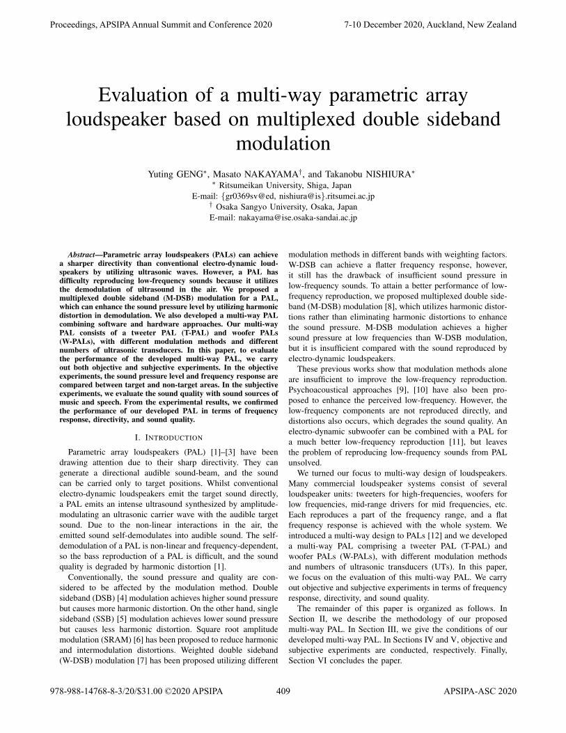
We proposed a multi-way PAL utilizing studies on modu-lation methods and hardware design for better low-frequencyreproduction. Fig.1 shows an overview of the proposed PAL,and Fig.2 shows the arrangement of a trial multi-way PALthat we developed on the basis of our proposal. The proposedmulti-way PAL consists of a T-PAL for low-frequency repro-duction and W-PAL for high-frequency reproduction.
A. Modulation methods
We utilized M-DSB modulation in the W-PALs for a betterlow-frequency reproduction, and SSB modulation in T-PAL forbetter high-frequency sound quality. As shown in Fig. 3, thetarget signal s(t) is first split into low-frequency sound sL(t)and high-frequency sound sH(t), which can be indicated as:
sL(t) = s(t) ∗ hLPFωco(t), (1)
sH(t) = s(t) ∗ hHPFωco(t), (2)
where t denotes the time index, ∗ denotes the convolutionoperator, and hLPFωco
(t) and hHPFωco(t) denote the low-pass
filter and high-pass filter with a crossover frequency ωco,respectively.
For high-frequency reproduction, an SSB modulated wavecan be generated by filtering out the upper sideband of a DSBmodulated wave, which can be indicated as:
uH(t) = {1 +mSSB · sH(t)} · c(t) ∗ hLPFfc(t), (3)
where mSSB denotes the modulation(0 < mSSB ≤ 1), c(t)denotes the carrier wave with frequency fC, and hLPFfC
(t)denotes the low-pass filter with a cut-off frequency the same
Fig. 1. Overview of the proposed multi-way PAL.
W-PAL T-PAL W-PAL
0.19 m
0.33 m 0.11 m 0.33 m
Fig. 2. Arrangement of the trial multi-way PAL.
Fig. 3. Modulation methods and signal processing of the proposed multi-wayparametric array loudspeaker.
as the carrier frequency fC. Ordinarily, a single frequencysinusoidal wave is utilized as the carrier wave, indicated asfollows:
c(t) = AC cos(2πfCt), (4)
where AC and fC denote the amplitude and frequency, respec-tively.
For low-frequency reproduction, an M-DSB modulatedwave can be generated by combining the DSB modulation anddouble sideband with suppressed carrier (DSB-SC) modulation[8]. As shown in Fig. 3, the low-frequency sound sL(t) isfirst compressed into sLF/2
(t), which is one octave lower. Inthe case that sL(t) is a pure tone, sL(t) and sLF/2
(t) can beindicated as:
sL(t) = AL cos(2πfLt), (5)sLF/2
(t) = AL cos(πfLt), (6)
where AL denotes the amplitude of sL(t). Then, DSB mod-ulation and DSB-SC modulation are carried out and the twomodulated waves are added to generate the M-DSB modulatedwave. The modulated waves emitted from the W-PAL can beindicated as
uL(t) =uDSB(t) + uSC(t)
={1 +mDSB · sL(t) +mSC · sLF/2(t)} · c(t)
=mDSBALAC
2cos(2π(fC ± fL)t)
+mSCALAC
2cos(2π(fC ± fL/2)t)
+AC cos(2πfCt),
(7)
where mDSB and mSC denote the modulation factor of DSBand DSB-SC modulation, respectively. It is known that theM-DSB modulated wave uL(t) consists of the carrier wave(frequency: fC), sidebands of the DSB modulated wave (fre-quency: fC ± fL), and sidebands of the DSB-SC modulatedwave (frequency: fC ± fL/2). fL can be demodulated fromthe difference between the DSB sideband and carrier wave,and also between the DSB-SC sidebands. On the other hand,though a half frequency distortion fL/2 is also generated, the
Proceedings, APSIPA Annual Summit and Conference 2020 7-10 December 2020, Auckland, New Zealand
410
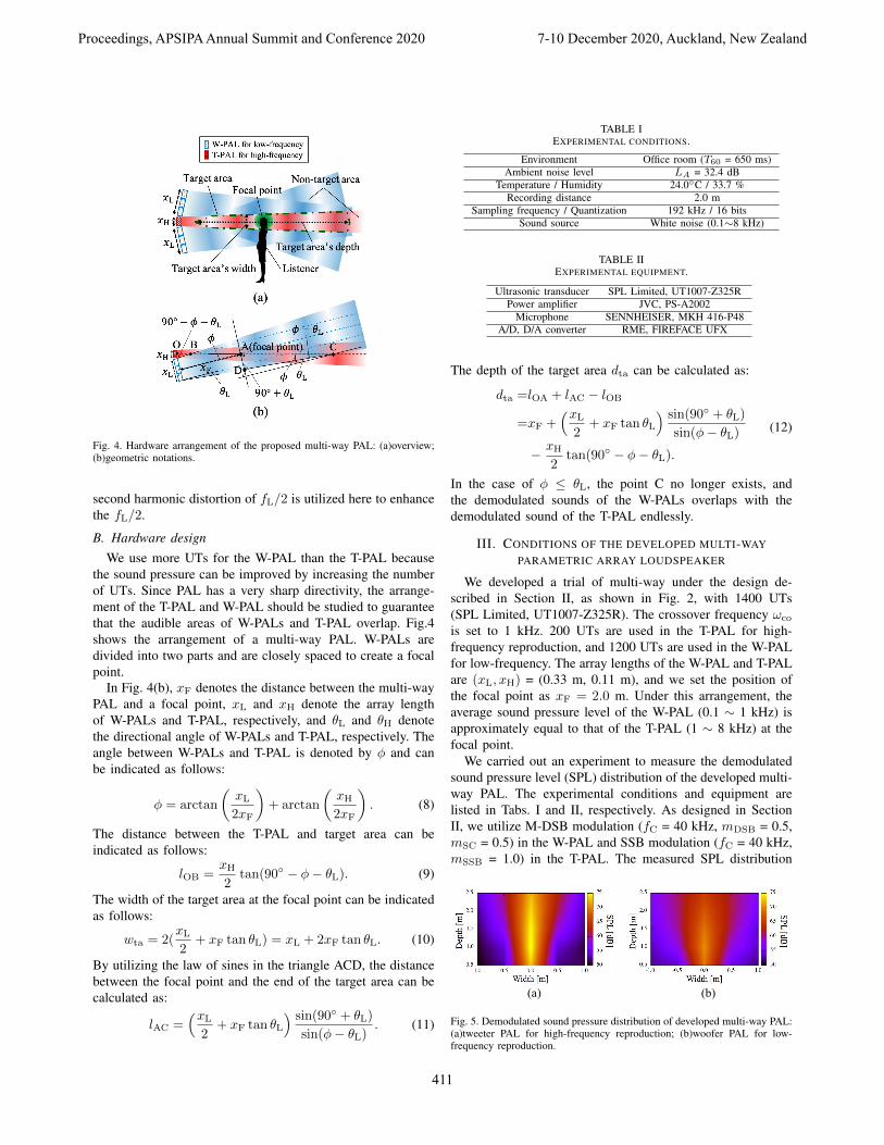
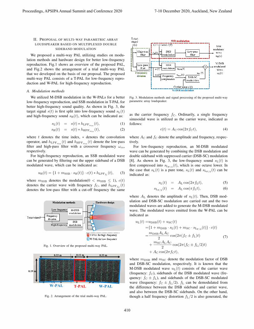
Fig. 4. Hardware arrangement of the proposed multi-way PAL: (a)overview;(b)geometric notations.
second harmonic distortion of fL/2 is utilized here to enhancethe fL/2.
B. Hardware designWe use more UTs for the W-PAL than the T-PAL because
the sound pressure can be improved by increasing the numberof UTs. Since PAL has a very sharp directivity, the arrange-ment of the T-PAL and W-PAL should be studied to guaranteethat the audible areas of W-PALs and T-PAL overlap. Fig.4shows the arrangement of a multi-way PAL. W-PALs aredivided into two parts and are closely spaced to create a focalpoint.
In Fig. 4(b), xF denotes the distance between the multi-wayPAL and a focal point, xL and xH denote the array lengthof W-PALs and T-PAL, respectively, and θL and θH denotethe directional angle of W-PALs and T-PAL, respectively. Theangle between W-PALs and T-PAL is denoted by φ and canbe indicated as follows:
φ = arctan
(xL2xF
)+ arctan
(xH2xF
). (8)
The distance between the T-PAL and target area can beindicated as follows:
lOB =xH2
tan(90◦ − φ− θL). (9)
The width of the target area at the focal point can be indicatedas follows:
wta = 2(xL2
+ xF tan θL) = xL + 2xF tan θL. (10)
By utilizing the law of sines in the triangle ACD, the distancebetween the focal point and the end of the target area can becalculated as:
lAC =(xL
2+ xF tan θL
) sin(90◦ + θL)
sin(φ− θL). (11)
TABLE IEXPERIMENTAL CONDITIONS.
Environment Office room (T60 = 650 ms)Ambient noise level LA = 32.4 dB
Temperature / Humidity 24.0◦C / 33.7 %Recording distance 2.0 m
Sampling frequency / Quantization 192 kHz / 16 bitsSound source White noise (0.1∼8 kHz)
TABLE IIEXPERIMENTAL EQUIPMENT.
Ultrasonic transducer SPL Limited, UT1007-Z325RPower amplifier JVC, PS-A2002
Microphone SENNHEISER, MKH 416-P48A/D, D/A converter RME, FIREFACE UFX
The depth of the target area dta can be calculated as:
dta =lOA + lAC − lOB
=xF +(xL
2+ xF tan θL
) sin(90◦ + θL)
sin(φ− θL)− xH
2tan(90◦ − φ− θL).
(12)
In the case of φ ≤ θL, the point C no longer exists, andthe demodulated sounds of the W-PALs overlaps with thedemodulated sound of the T-PAL endlessly.
III. CONDITIONS OF THE DEVELOPED MULTI-WAYPARAMETRIC ARRAY LOUDSPEAKER
We developed a trial of multi-way under the design de-scribed in Section II, as shown in Fig. 2, with 1400 UTs(SPL Limited, UT1007-Z325R). The crossover frequency ωco
is set to 1 kHz. 200 UTs are used in the T-PAL for high-frequency reproduction, and 1200 UTs are used in the W-PALfor low-frequency. The array lengths of the W-PAL and T-PALare (xL, xH) = (0.33 m, 0.11 m), and we set the position ofthe focal point as xF = 2.0 m. Under this arrangement, theaverage sound pressure level of the W-PAL (0.1 ∼ 1 kHz) isapproximately equal to that of the T-PAL (1 ∼ 8 kHz) at thefocal point.
We carried out an experiment to measure the demodulatedsound pressure level (SPL) distribution of the developed multi-way PAL. The experimental conditions and equipment arelisted in Tabs. I and II, respectively. As designed in SectionII, we utilize M-DSB modulation (fC = 40 kHz, mDSB = 0.5,mSC = 0.5) in the W-PAL and SSB modulation (fC = 40 kHz,mSSB = 1.0) in the T-PAL. The measured SPL distribution
(a) (b)
Fig. 5. Demodulated sound pressure distribution of developed multi-way PAL:(a)tweeter PAL for high-frequency reproduction; (b)woofer PAL for low-frequency reproduction.
Proceedings, APSIPA Annual Summit and Conference 2020 7-10 December 2020, Auckland, New Zealand
411
of the T-PAL and W-PAL are shown in Fig. 5 (a) and (b),respectively. We then calculated the directivity angle of eachPAL, which is defined as the angle to the point where theSPL of the demodulated sound is attenuated at 6.0 dB in thehorizontal direction of the focal point. The directional angle ofthe W-PAL is θL = 15.8◦ and that of the T-PAL is θH = 7.9◦.Substituting these measured parameters into Eq. (8), φ = 6.3◦.Therefore, on the basis of our theoretical analysis in SectionII-B, the condition φ ≤ θL is satisfied, and it is known thatthe demodulated sounds of W-PALs and T-PAL will overlapall the way in the propagation direction. Moreover, the widthof target area wta is measured to be about 0.7 m, which isconsidered large enough for the size of a human head.
IV. OBJECTIVE EVALUATION EXPERIMENTS
A. Conditions of objective experiments
In our developed multi-way PAL, we utilized M-DSBmodulation and SSB modulation in the W-PAL and T-PALwith different numbers of UTs to achieve a flatter frequencyresponse. Therefore, we carried out objective experimentson the frequency response to confirm the effectiveness. Asshown in Fig. 6, we observed the demodulated sounds atthree positions: focal point (0 m, 2.0 m), (0 m, 1.0 m) forthe target area and (1.0 m, 2.0 m) for the non-target area.We also compare the performance of the developed multi-wayPAL when utilizing different modulation methods as shownin Tab. III. Here, in the cases of “SSB” “DSB,” and “M-DSB,” we set no crossover so the same signal is reproducedfrom the W-PAL and T-PAL. In the case of “Proposed,” weset the crossover frequency ωco = 1 kHz. A signal witha frequency higher than ωco is emitted from the T-PAL,modulated by SSB modulation, and a signal with a frequency
Fig. 6. Experimental arrangement (vertical view).
TABLE IIICOMPARISON IN EVALUATION EXPERIMENTS.
Index Modulation in W-PAL Modulation in T-PAL(Low-frequency) (High-frequency)
SSB SSB SSBDSB DSB DSB
M-DSB M-DSB M-DSBProposed M-DSB SSB
lower than ωco is emitted from the W-PAL, modulated by M-DSB modulation. A time-stretched pulse (TSP) signal (0 ∼ 8kHz) is utilized in the measurement of the frequency response[13]. A modulated TSP signal is emitted from the PAL, andthe demodulated sounds are recorded at observation positions.Other experimental conditions and equipment are the same asthose shown in Tabs. I and II, respectively.
To evaluate the flatness of the frequency response, wecalculated the average error of observed power spectra Perr,which is defined as follows:
Perr =1
fmax − fmin
fmax∑f=fmin
|P (f)− Pµ|, (13)
where Pµ denotes the average of the observed power spectrum.A smaller Perr suggests a flatter frequency response.
Fig. 7. Power spectra of demodulated sounds observed at different positions:(a) focal point (0 m, 2.0 m); (b) target area (0 m, 1.0 m); (c) non-target area(1.0 m, 2.0 m).
Proceedings, APSIPA Annual Summit and Conference 2020 7-10 December 2020, Auckland, New Zealand
412
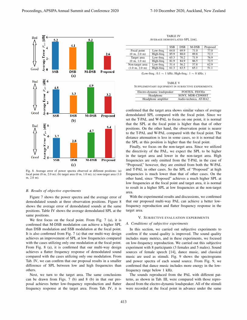
Fig. 8. Average error of power spectra observed at different positions: (a)focal point (0 m, 2.0 m); (b) target area (0 m, 1.0 m); (c) non-target area (1.0m, 2.0 m).
B. Results of objective experiments
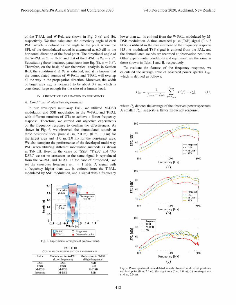
Figure 7 shows the power spectra and the average error ofdemodulated sounds at three observation positions. Figure 8shows the average error of demodulated sounds at the samepositions. Table IV shows the average demodulated SPL at thesame positions.
We first focus on the focal point. From Fig. 7 (a), it isconfirmed that M-DSB modulation can achieve a higher SPLthan DSB modulation and SSB modulation at the focal point.It is also confirmed from Fig. 7 (a) that our multi-way designachieves an improvement of SPL at low frequencies comparedwith the cases utilizing only one modulation at the focal point.From Fig. 8 (a), it is confirmed that our multi-way designachieves a flatter frequency response of demodulated soundcompared with the cases utilizing only one modulation. FromTab. IV, we can confirm that our proposal results in a smallerdifference of SPL between low and high frequencies thanothers.
Next, we turn to the target area. The same conclusionscan be drawn from Figs. 7 (b) and 8 (b) in that our pro-posal achieves better low-frequency reproduction and flatterfrequency response at the target area. From Tab. IV, it is
TABLE IVAVERAGE DEMODULATED SPL [DB].
SSB DSB M-DSB ProposedFocal point
(0 m, 2.0 m)Low-freq. 64.8 69.9 71.0 77.0High-freq. 85.9 88.0 89.8 72.3
Target area(0 m, 1.0 m)
Low-freq. 65.3 70.2 71.9 76.9High-freq. 81.9 84.9 86.5 72.5
Non-target area(1.0 m, 2.0 m)
Low-freq. 51.4 56.2 57.8 62.9High-freq. 61.3 63.5 65.1 51.1
(Low-freq.: 0.1 ∼ 1 kHz; High-freq.: 1 ∼ 8 kHz; )
TABLE VSUPPLEMENTARY EQUIPMENT IN SUBJECTIVE EXPERIMENTS.
Electro-dynamic loudspeaker FOSTEX, FE83EnHeadphone SONY, MDR-CD900ST
Headphone amplifier Audio-technica, AT-HA2
confirmed that the target area shows similar values of averagedemodulated SPL compared with the focal point. Since weset the T-PAL and W-PAL to focus on one point, it is normalthat the SPL at the focal point is higher than that of otherpositions. On the other hand, the observation point is nearerto the T-PAL and W-PAL compared with the focal point. Thedistance attenuation is less in some cases, so it is normal thatthe SPL at this position is higher than the focal point.
Finally, we focus on the non-target area. Since we utilizedthe directivity of the PAL, we expect the SPL to be higherin the target area and lower in the non-target area. Highfrequencies are only emitted from the T-PAL in the case of“Proposed,” however, they are emitted from both the W-PALand T-PAL in other cases. So the SPL of “Proposed” at highfrequencies is much lower than that of other cases. On theother hand, since “Proposed” achieves a much higher SPL atlow frequencies at the focal point and target area, it is normalto result in a higher SPL at low frequencies at the non-targetarea.
With the experimental results and discussions, we confirmedthat our proposed multi-way PAL can achieve a better low-frequency reproduction and flatter frequency response in thetarget area.
V. SUBJECTIVE EVALUATION EXPERIMENTS
A. Conditions of subjective experiments
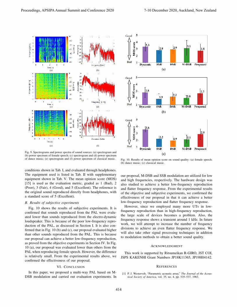
In this section, we carried out subjective experiments toconfirm if the sound quality is improved. The sound qualityincludes many metrics, and in these experiments, we focusedon low-frequency reproduction. We carried out this subjectiveexperiment with 8 participants (3 females and 5 males). Soundsources of female speech [14], dance music, and classicalmusic are used as stimuli. Fig. 9 shows the spectrogramsand power spectra of each sound source. From Fig. 9, weconfirmed that dance music includes more energy in the low-frequency range below 1 kHz.
The sounds reproduced from the PAL with different pat-terns, as shown in Tab. III, were compared with those repro-duced from the electro-dynamic loudspeaker. All of the stimuliwere recorded at the focal point in advance under the same
Proceedings, APSIPA Annual Summit and Conference 2020 7-10 December 2020, Auckland, New Zealand
413
(a) (b)
(c) (d)
(e) (f)
Fig. 9. Spectrograms and power spectra of sound sources: (a) spectrogram and(b) power spectrum of female speech; (c) spectrogram and (d) power spectrumof dance music; (e) spectrogram and (f) power spectrum of classical music.
conditions shown in Tab. I, and evaluated through headphones.The equipment used is listed in Tab. II with supplementaryequipment shown in Tab. V. The mean opinion score (MOS)[15] is used as the evaluation metric, graded as 1 (Bad), 2(Poor), 3 (Fair), 4 (Good), and 5 (Excellent). The reference isthe original sound reproduced directly from headphones, witha standard score of 5 (Excellent).
B. Results of subjective experiments
Fig. 10 shows the results of subjective experiments. It isconfirmed that sounds reproduced from the PAL were evalu-ated lower than sounds reproduced from the electro-dynamicloudspeaker. This is because of the poor low-frequency repro-duction of the PAL, as discussed in Section I. It is also con-firmed that in Fig. 10 (b) and (c), our proposal evaluated higherthan other sounds reproduced from the PAL. This is becauseour proposal can achieve a better low-frequency reproduction,as proved from the objective experiments in Section IV. In Fig.10 (a), our proposal was evaluated lower than others from thePAL when reproducing female speech. However, the differenceis relatively small. From the experimental results above, weconfirmed the effectiveness of our proposal.
VI. CONCLUSION
In this paper, we proposed a multi-way PAL based on M-DSB modulation and carried out evaluation experiments. In
Fig. 10. Results of mean opinion score on sound quality: (a) female speech;(b) dance music; (c) classical music.
our proposal, M-DSB and SSB modulation are utilized for lowand high frequencies, respectively. The hardware design wasalso studied to achieve a better low-frequency reproductionand flatter frequency response. From the experimental resultsof the objective and subjective experiments, we confirmed theeffectiveness of our proposal in that it can achieve a betterlow-frequency reproduction and flatter frequency response.
However, since we employed many more UTs in low-frequency reproduction than in high-frequency reproduction,the large scale of devices becomes a problem. Also, thefrequency response shows a transient around 1 kHz. In futurework, we will attempt to increase the number of frequencydivisions to achieve an even flatter frequency response. Wewill also take other signal processing techniques in additionto modulation methods to obtain a better sound quality.
ACKNOWLEDGMENT
This work is supported by Ritsumeikan R-GIRO, JST COI,JSPS KAKENHI Grant Numbers JP18K11365, JP19H04142.
REFERENCES
[1] P. J. Westervelt, “Parametric acoustic array,” The Journal of the Acous-tical Society of America, vol. 35, no. 4, pp. 535–537, 1963.
Proceedings, APSIPA Annual Summit and Conference 2020 7-10 December 2020, Auckland, New Zealand
414
[2] K. Aoki, T. Kamakura, and Y. Kumamoto, “Parametric loudspeaker-characteristics of acoustic field and suitable modulation of carrierultrasound,” Electronics and Communications in Japan, vol. 74, no. 9,pp. 76–82, 1991.
[3] W. S. Gan, J. Yang, and T. Kamakura, “A review of parametric acousticarray in air,” Applied Acoustics, vol. 73, no. 12, pp. 1211–1219, 2012.
[4] M. Yoneyama, J. Fujimoto, Y. Kawamo, and S. Sasabe, “The audiospotlight: An application of nonlinear interaction of sound waves to anew type of loudspeaker design,” The Journal of the Acoustical Societyof America, vol. 73, no. 5, pp. 1532–1536, 1983.
[5] K. Aoki, T. Kamakura, and Y. Kumamoto, “Parametric loudspeaker–characteristics of acoustic field and suitable modulation of carrierultrasound,” Electronics and Communications in Japan (Part III: Fun-damental Electronic Science), vol. 74, no. 9, pp. 76–82, 1991.
[6] T. Kamakura, “Developments of parametric loudspeaker for practicaluse,” in Proc. 10th International Symposium on Non-linear Acoustics,pp. 147–150, 1984.
[7] D. Ikefuji, M. Nakayama, T. Nishiura, and Y. Yamashita, “Weighteddouble sideband modulation toward high quality audible sound onparametric loudspeaker,” in 2013 IEEE International Conference onAcoustics, Speech and Signal Processing, pp. 843–847, 2013.
[8] Y. Nakano, T. Fukumori, M. Nakayama, and T. Nishiura, “A study onaudible low-frequency sound emphasis based on multiplexed doublesideband modulation in parametric loudspeaker,” in INTER-NOISE andNOISE-CON Congress and Conference Proceedings, vol. 258, no. 5, pp.2054–2065, 2018.
[9] C. Shi, H. Mu, and W. S. Gan, “A psychoacoustical preprocessingtechnique for virtual bass enhancement of the parametric loudspeaker,”in 2013 IEEE International Conference on Acoustics, Speech and SignalProcessing. pp. 31–35, 2013.
[10] Y. Geng, M. Nakayama, and T. Nishiura, “Virtual bass enhancementbased on harmonics control using missing fundamental in parametricarray loudspeaker,” in INTER-NOISE and NOISE-CON Congress andConference Proceedings, vol. 259, no. 7, pp. 2660–2671, 2019.
[11] Y. Sugibayashi, S. Kurimoto, D. Ikefuji, M. Morise, and T. Nishiura,“Three-dimensional acoustic sound field reproduction based on hybridcombination of multiple parametric loudspeakers and electrodynamicsubwoofer,” Applied Acoustics, vol. 73, no. 12, pp. 1282–1288, 2012.
[12] Y. Geng, Y. Nakano, M. Nakayama, and T. Nishiura, “Developmentof multi-way parametric array loudspeaker using multiplexed doublesideband modulation,” in 23rd International Congress on Acoustics, pp.1069–1076, 2019.
[13] N. Aoshima, “Computer-generated pulse signal applied for sound mea-surement,” The Journal of the Acoustical Society of America, vol. 69,no. 5, pp. 1484–1488, 1981.
[14] A. Kurematsu, K. Takeda, Y. Sagisaka, S. Katagiri, H. Kuwabara,and K. Shikano, “ATR Japanese speech database as a tool of speechrecognition and synthesis,” Speech communication, vol. 9, no. 4, pp.357–363, 1990.
[15] Rec. ITU-R P. 800:, “Methods for subjective determination of transmis-sion quality,” 1996.
Proceedings, APSIPA Annual Summit and Conference 2020 7-10 December 2020, Auckland, New Zealand
415
Recommended


![Development of A Steerable Stereophonic Parametric Loudspeaker · Development of A Steerable Stereophonic Parametric Loudspeaker Chuang Shi , ... [13]. Therefore, the ... When the](https://img.dokumen.tips/doc/110x75/5aef235b7f8b9aa9168c2768/development-of-a-steerable-stereophonic-parametric-of-a-steerable-stereophonic-parametric.jpg)


