August 2013
Environmental Statement Chapter 5 Project Description Application Reference: 6.5
DOGGER BANK CREYKE BECK
F-OFC-CH-005 Issue 4 © 2013 Forewind Chapter 5 Page ii
Document Title Dogger Bank Creyke Beck
Environmental Statement – Chapter 5
Project Description
Forewind Document Reference F-OFC-CH-005 Issue 4
Date August 2013
Drafted by Forewind
Checked by Adrian Pattison
Date / initials check AP 05/08/2013
Approved by Mark Legerton
Date / initials approval ML 05/08/2013
Forewind Approval FAC
Date / Reference approval FAC 05/08/2013
DOGGER BANK CREYKE BECK
F-OFC-CH-005 Issue 4 © 2013 Forewind Chapter 5 Page iii
Title: Dogger Bank Creyke Beck Environmental Statement - Chapter 5 Project Description
Contract No. (if applicable) (Onshore / Offshore)
Document Number: F-OFC-CH-005
Issue No: 4
Issue Date: 05-Aug-13
Status: Issued for 1st. Technical Review Issued for 2nd. Technical Review
Issued for PEI3 Issued for Application Submission
Prepared by:
Forewind Engineering & Electrical Teams
Checked by:
Adrian Pattison / Sophie Barrell
Approved by: Mark Legerton
Signature / Approval (Forewind)
Mark Legerton
Approval Date: 05-Aug-13
Revision History
Date Issue No. Remarks / Reason for Issue Author Checked Approved
31/10/2012 1 Draft for first technical review Forewind ER AP
21/01/2013 2 Draft for second technical review Forewind ER ML
21/03/2013 3 Issued for PEI3 Forewind AP ML
05/08/2013 4 Issued for Application Submission Forewind AP ML

DOGGER BANK CREYKE BECK
F-OFC-CH-005 Issue 4 © 2013 Forewind Chapter 5 Page iv
Contents
1 Introduction ................................................................................................................... 1
1.1 Overview ............................................................................................................. 1
1.2 Project Development Envelope - Flexibility ......................................................... 1
1.3 Project Description - Summary ........................................................................... 2
1.4 Project Capacities & Overplanting ...................................................................... 8
1.5 Project Output & Electricity Generation ............................................................... 8
1.6 Links to the Development Consent Order ........................................................... 9
1.7 Relevant Guidance ........................................................................................... 11
1.8 Consultation ...................................................................................................... 14
2 Site Description ........................................................................................................... 21
2.1 Site Location ..................................................................................................... 21
2.2 Offshore Site Description .................................................................................. 36
2.3 Onshore Site Description .................................................................................. 37
3 Offshore Project Components ..................................................................................... 40
3.1 Wind Turbines ................................................................................................... 40
3.2 Offshore Structure Foundations ........................................................................ 50
3.3 Protection Against Foundation Scour & Subsea Damage ................................. 78
3.4 Grout ................................................................................................................. 82
3.5 Seabed Preparation, Drilling & Disposal of Spoil Arisings ................................ 83
3.6 Piling & Noise Modelling ................................................................................... 88
3.7 Offshore Platforms ............................................................................................ 97
3.8 Offshore Cables .............................................................................................. 104
3.9 Offshore Cable Installation and Removal ........................................................ 110
3.10 Remedial Cable Protection ............................................................................. 118
3.11 Offshore Cable & Pipeline Crossings .............................................................. 124
3.12 Offshore Electromagnetic Fields ..................................................................... 129
3.13 Meteorological Monitoring Stations ................................................................. 133
3.14 Vessel Moorings ............................................................................................. 136
4 Onshore Project Components ................................................................................... 139
4.1 Cable Landfall ................................................................................................. 139
DOGGER BANK CREYKE BECK
F-OFC-CH-005 Issue 4 © 2013 Forewind Chapter 5 Page v
4.2 Onshore Cables .............................................................................................. 142
4.3 Onshore Cable Routes ................................................................................... 145
4.4 Cable Installation ............................................................................................ 149
4.5 Onshore Construction ..................................................................................... 163
4.6 Onshore Converter Station ............................................................................. 174
4.7 Expected Construction Traffic ......................................................................... 178
5 Offshore Project Layouts ........................................................................................... 179
5.1 Wind Farm Layouts ......................................................................................... 179
5.2 Wind Turbine Array Layout Rules ................................................................... 180
5.3 Layout of Other Offshore Project Components ............................................... 187
5.4 Wind Turbine Spacing ..................................................................................... 187
5.5 Proximity to Existing Infrastructure .................................................................. 188
6 Project Life Cycle ...................................................................................................... 190
6.2 Pre-Construction Engineering Surveys ........................................................... 190
6.3 Construction .................................................................................................... 191
6.4 Commissioning ............................................................................................... 204
6.5 Operation & Maintenance ............................................................................... 205
6.6 Replanting/Life Extension ............................................................................... 214
6.7 Decommissioning ............................................................................................ 215
7 Health & Safety and Environmental Management .................................................... 220
7.1 Health and Safety ........................................................................................... 220
7.2 Waste Management ........................................................................................ 220
7.3 Hazardous Material ......................................................................................... 222
7.4 Safety Zones and Other Potential Navigation Safety Measures ..................... 224
7.5 Navigation and Aviation Safety Markings ........................................................ 225
DOGGER BANK CREYKE BECK
F-OFC-CH-005 Issue 4 © 2013 Forewind Chapter 5 Page vi
Table of Tables
Table 1.1: Summary of key project components ........................................................... 6
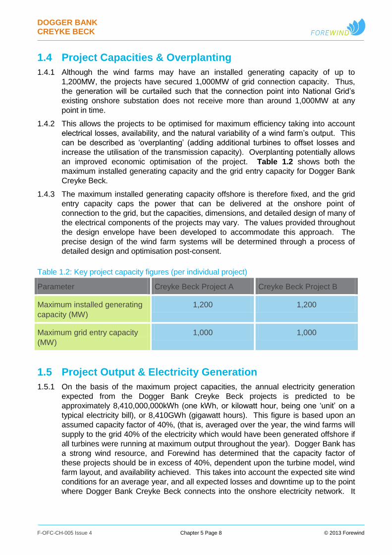
Table 1.2: Key project capacity figures (per individual project) ..................................... 8
Table 1.3: NPS requirements ...................................................................................... 11
Table 1.4: Summary of key consultation and issues raised by consultees.................. 15
Table 2.1: Key Zone characteristics ............................................................................ 21
Table 2.2: Dogger Bank Creyke Beck A key project characteristics............................ 23
Table 2.3: Dogger Bank Creyke Beck A boundary co-ordinates ................................. 24
Table 2.4: Dogger Bank Creyke Beck B key project characteristics............................ 24
Table 2.5: Dogger Bank Creyke Beck B boundary co-ordinates ................................. 25
Table 2.6: Export cable corridor key co-ordinates (major vertices) ............................. 28
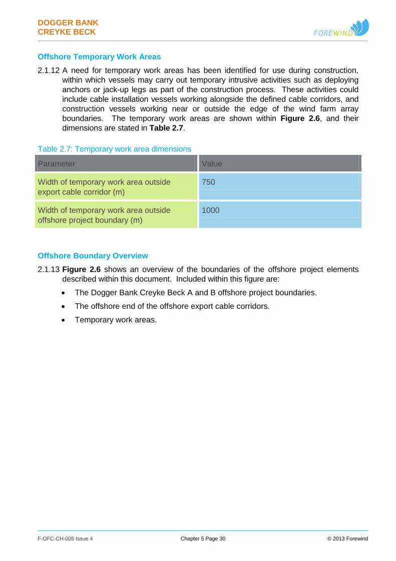
Table 2.7: Temporary work area dimensions .............................................................. 30
Table 3.1: Indicative wind turbine parameters per project ........................................... 41
Table 3.2: Indicative hazardous materials peak quantities during normal operation ... 48
Table 3.3: Indicative wind turbine monopole foundation parameters .......................... 52
Table 3.4: Indicative wind turbine multileg foundation parameters .............................. 57
Table 3.5: Indicative wind turbine gravity base foundation parameters ....................... 66
Table 3.6: Indicative offshore platform multileg foundation parameters ...................... 70
Table 3.7: Indicative offshore platform gravity base foundation parameters ............... 73
Table 3.8: Indicative wind turbine foundation subsea/scour protection parameters .... 80
Table 3.9: Indicative offshore platform and meteorological station foundation
subsea/scour protection parameters ........................................................................... 80
Table 3.10: Indicative grout volume parameters covering all potential grouting
requirements ............................................................................................................... 82
Table 3.11: Indicative wind turbine foundation seabed preparation parameters ......... 85
Table 3.12: Indicative offshore platform and meteorological station foundation seabed
preparation parameters ............................................................................................... 85
Table 3.13: Indicative drill arising parameters ............................................................. 87
Table 3.14: Wind turbine and meteorological station foundation indicative piling
parameters .................................................................................................................. 89
Table 3.15: Offshore platform foundation indicative piling parameters........................ 90
DOGGER BANK CREYKE BECK
F-OFC-CH-005 Issue 4 © 2013 Forewind Chapter 5 Page vii
Table 3.16: Indicative collector platform parameters ................................................... 99
Table 3.17: Indicative offshore converter platform parameters ................................. 101
Table 3.18: Indicative accommodation or helicopter platform parameters ................ 103
Table 3.19: Indicative inter-array cable parameters .................................................. 106
Table 3.20: Indicative inter-platform cable parameters ............................................. 107
Table 3.21: Indicative offshore HVDC export cable parameters ............................... 109
Table 3.22: Indicative offshore cable remedial protection parameters ...................... 119
Table 3.23: Indicative crossing protection parameters .............................................. 128
Table 3.24: Example of compass deviation assessment results ............................... 131
Table 3.25: Indicative mooring buoy parameters ...................................................... 137
Table 4.1: Indicative onshore HVDC cable parameters ............................................ 143
Table 4.2: Indicative onshore HVAC cable parameters ............................................. 144
Table 4.3: Indicative onshore route parameters, per project ..................................... 146
Table 4.4: Indicative breakdown of working widths for typical cable corridor
construction works .................................................................................................... 148
Table 4.5: Typical cable trench dimensions per project ............................................ 149
Table 4.6: Plant and Vehicles indicatively required for trench excavation ................. 152
Table 4.7: Plant and Vehicles indicatively required for installation of ducts .............. 154
Table 4.8: Plant and vehicles indicatively required for HDD site survey and bore
planning .................................................................................................................... 155
Table 4.9: Plant and vehicles indicatively required for setting out pits ...................... 158
Table 4.10: Plant and vehicles indicatively required for HDD operations .................. 160
Table 4.11: Plant and Vehicles indicatively required for removal of HDD Sites ........ 162
Table 4.12: Indicative cable construction compound sizes ....................................... 163
Table 4.13: Plant and vehicles indicatively required for setting out and fencing ....... 167
Table 4.14: Plant and vehicles indicatively required for haul road construction and top-
soil strip ..................................................................................................................... 170
Table 4.15: Plant and vehicles indicatively required for cable delivery, storage and
installation works ....................................................................................................... 172
Table 4.16: Plant and vehicles indicatively required for site demobilisation works .... 173
Table 4.17: Indicative converter substation parameters per project .......................... 176
Table 4.18: Indicative number of deliveries expected for the onshore works ............ 178
Table 5.1: Wind turbine spacing parameters ............................................................. 187

DOGGER BANK CREYKE BECK
F-OFC-CH-005 Issue 4 © 2013 Forewind Chapter 5 Page viii
Table 5.2: Indicative separation distances from other marine users existing operational
infrastructure (measured centre to centre) ................................................................ 189
Table 6.1: Indicative construction programme parameters, per project..................... 192
Table 6.2: Onshore HVDC cable construction options .............................................. 193
Table 6.3: Onshore HVAC cable construction options .............................................. 194
Table 6.4: Onshore converter station construction options ....................................... 195
Table 6.5: Indicative project construction ports and distances to the centroids of
projects ..................................................................................................................... 197
Table 6.6: Indicative vessel movements to port during construction ......................... 198
Table 6.7: Indicative annual helicopter movements to shore during construction ..... 199
Table 6.8: Potential onshore construction vehicles ................................................... 202
Table 6.9: Indicative O&M ports for Dogger Bank Creyke Beck and distances to
centroids of the projects ............................................................................................ 206
Table 6.10: Indicative O&M vessel numbers per project for a representative vessel-
based strategy .......................................................................................................... 209
Table 6.11: Indicative annual O&M vessel journeys to port per project for a
representative vessel-based strategy ........................................................................ 210
Table 6.12: Indicative annual O&M helicopter journeys per project for a helicopter-
based strategy .......................................................................................................... 210
Table of Figures
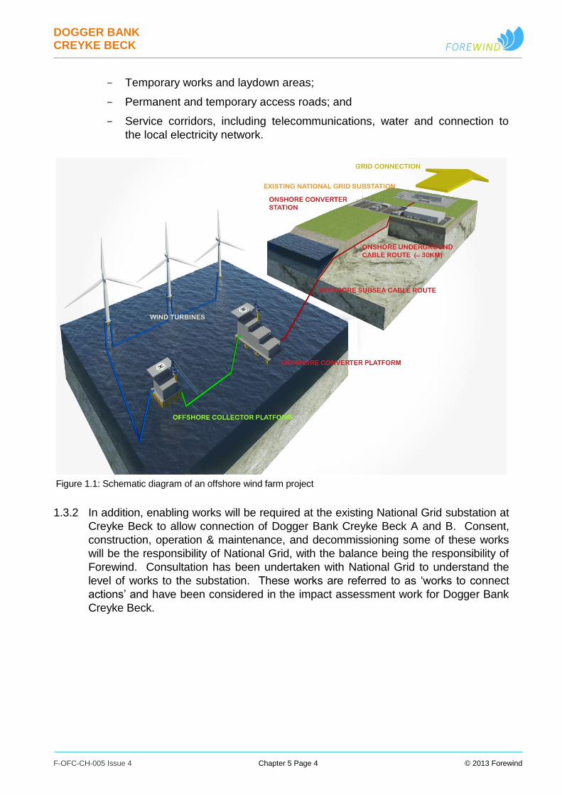
Figure 1.1: Schematic diagram of an offshore wind farm project .................................. 4
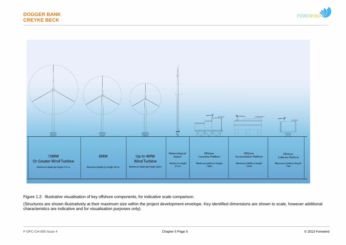
Figure 1.2: Illustrative visualisation of key offshore components, for indicative scale
comparison. .................................................................................................................. 5
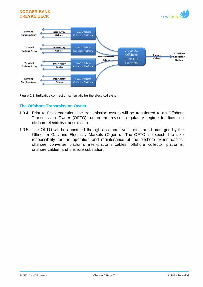
Figure 1.3: Indicative connection schematic for the electrical system ........................... 7
Figure 2.1: Dogger Bank Zone .................................................................................... 21
Figure 2.2: Dogger Bank Tranche A boundary ............................................................ 22
Figure 2.3: Dogger Bank Creyke Beck A boundary co-ordinates ................................ 23
Figure 2.4: Dogger Bank Creyke Beck B boundary co-ordinates ................................ 25
Figure 2.5: The offshore export cable corridor ............................................................ 27
Figure 2.6: Overview of offshore boundaries .............................................................. 31
Figure 2.7: Overview of onshore cable corridor .......................................................... 33
DOGGER BANK CREYKE BECK
F-OFC-CH-005 Issue 4 © 2013 Forewind Chapter 5 Page ix
Figure 2.8: Proposed Converter Stations Location ..................................................... 35
Figure 2.9: Indicative annual wind rose for Dogger Bank Zone Tranche A ................. 37
Figure 3.2: Indicative drawing of an up to 4MW wind turbine ...................................... 43
Figure 3.3: Indicative drawing of 6MW wind turbine .................................................... 44
Figure 3.4: Indicative drawing of 10MW or greater wind turbine ................................. 45
Figure 3.5: Illustration of the components of a typical geared wind turbine ................. 46
Figure 3.6: Illustrative example of a steel monopile foundation ................................... 53
Figure 3.7: Illustrative visualisation of the installation of concrete monopile ............... 54
Figure 3.8: Illustrative examples of suction bucket monopole foundations .................. 55
Figure 3.9: Illustrative examples of multileg foundation structures .............................. 58
Figure 3.10: Examples of driven pile multileg foundations .......................................... 60
Figure 3.11: Examples of existing suction bucket multileg foundations (left) and
concept designs (right) ................................................................................................ 61
Figure 3.12: Illustrative visualisation of screw pile multileg foundation........................ 62
Figure 3.13: Illustrative example of jack-up foundation ............................................... 64
Figure 3.14: Illustrative examples of conical gravity base foundations ........................ 66
Figure 3.15: Illustrative examples of flat based gravity foundations. ........................... 67
Figure 3.17: Illustrative example of a hybrid jacket/jack up platform foundation ......... 71
Figure 3.18: Illustrative example of a semi-submersible gravity base foundation ....... 74
Figure 3.19: Typical wind turbine transition pieces...................................................... 75
Figure 3.20: Example of gravity base structure with scour protection. ........................ 78
Figure 3.21: Example of a suction bucket monopole foundation with scour protection
79
Figure 3.22: Example of multileg suction bucket foundation with scour protection ..... 81
Figure 3.23: Indicative diagram showing gravity base foundation with bedding material
83
Figure 3.24: Indicative diagram showing gravity base foundation with shallow
excavation filled with bedding material ........................................................................ 84
Figure 3.25: Impact piling noise propagation map, for relatively flat bathymetry profile
and a 3,000kJ hammer blow energy ........................................................................... 96
Figure 3.26: Modelled noise map for operational noise at Creyke Beck A, assuming a
700m turbine spacing .................................................................................................. 96
Figure 3.27: Illustrative example of an offshore platform............................................. 97
DOGGER BANK CREYKE BECK
F-OFC-CH-005 Issue 4 © 2013 Forewind Chapter 5 Page x
Figure 3.28: Typical offshore collector platform design ............................................... 98
Figure 3.29: Example of an offshore accommodation platform ................................. 102
Figure 3.30: Illustrative schematic of offshore cable layout ....................................... 104
Figure 3.31: Indicative illustration of a typical inter-platform cable. ........................... 106
Figure 3.32: A cutaway of a typical HVDC offshore cable ......................................... 108
Figure 3.33: Team Oman cable installation vessel ................................................... 112
Figure 3.34: Illustrative example of a shallow draft work barge ................................. 112
Figure 3.35: Example of a grounded cable lay barge during installation of a near-shore
cable section ............................................................................................................. 113
Figure 3.36: Illustrative example of an offshore cable plough ................................... 114
Figure 3.37: Example of an ROV equipped with a jetting system ............................. 115
Figure 3.38: Illustrative example of a mechanical trenching system ......................... 115
Figure 3.39: Illustrative visualisation of a mass flow excavation system in operation 116
Figure 3.41: Illustrative example of rock berm protection for unburied inter-array
cables ........................................................................................................................ 120
Figure 3.42: Illustrative example of rock berm protection for unburied export cables 121
Figure 3.43: Illustrative example of concrete mattress cable protection .................... 121
Figure 3.45: Illustrative example of cable protective covering ................................... 123
Figure 3.46: Illustrative example of a rock-filled bag for cable protection .................. 123
Figure 3.47: Illustrative example of a grout bag ........................................................ 124
Figure 3.48: Illustrative example of crossing design for inter-array cables (cross
sectional view) .......................................................................................................... 126
Figure 3.49: Illustrative example of crossing design for inter-array cables (plan view)
126
Figure 3.50: Illustrative example of crossing design for export cables (cross section)
127
Figure 3.51: Illustrative example of crossing design for export cables (plan view) .... 127
Figure 3.52: Illustrative representations of the Earth’s magnetic field (left), and the
magnetic field around a pair of DC cables (right) ...................................................... 129
Figure 3.53: Example of compass deviation from a pair of HVDC cables at 50m
separation ................................................................................................................. 131
Figure 3.54: Planned development-phase meteorological mast locations, anticipated
to be installed in 2013 ............................................................................................... 133

DOGGER BANK CREYKE BECK
F-OFC-CH-005 Issue 4 © 2013 Forewind Chapter 5 Page xi
Figure 3.55: Illustrative example of a fixed meteorological monitoring station .......... 134
Figure 3.56: Example of a floating meteorological monitoring station, including a wind
lidar 134
Figure 3.57: Illustrative example of a single buoy mooring ....................................... 136
Figure 3.58: Illustrative example of a single buoy mooring with six gravity anchors . 137
Figure 4.1: Example of typical HDD equipment ........................................................ 140
Figure 4.2: Example of a sheet piled cofferdam being installed on a beach ............. 141
Figure 4.3: A cutaway view of a typical onshore HVDC cable ................................... 143
Figure 4.4: A typical 400kV HVAC cable ................................................................... 144
Figure 4.5: Indicative onshore cable route working widths based on two illustrative
construction options for an HVDC section ................................................................. 147
Figure 4.6: Indicative cross section of a direct burial trench ...................................... 150
Figure 4.7: Example of close timbered trench ........................................................... 151
Figure 4.8: Indicative cross section of ducted trench installation of onshore HVDC
cables ........................................................................................................................ 153
Figure 4.9: Typical arrangement of a large HDD launch site ..................................... 156
Figure 4.10: Typical arrangement of large HDD reception site ................................. 157
Figure 4.11: Illustrative visualisation of an HDD Installation ...................................... 159
Figure 4.12: Schematic diagram showing a typical HDD through an eroding coastline
161
Figure 4.13: Indicative arrangement of a typical primary site compound .................. 165
Figure 4.14: Indicative arrangement of a typical intermediate site compound ........... 166
Figure 4.15: Example of a temporary vehicle bridge ................................................. 168
Figure 4.16: Example of a cable drum delivery to cable storage area....................... 171
Figure 4.17: Example of a cement bound sand delivery ........................................... 171
Figure 4.18: Example of cable installation swathe after topsoil reinstatement .......... 174
Figure 4.19: Typical converter station layout ............................................................. 174
Figure 5.1: Illustrative Layout 1 - Perimeter plus regular grid .................................... 182
Figure 5.2: Illustrative Layout 2 - perimeter plus stripes ............................................ 183
Figure 5.3: Illustrative Layout 3 - regular grid ............................................................ 184
Figure 5.4: Illustrative Layout 4 – reduced area regular grid ..................................... 185
Figure 5.5: Illustrative Layout 5 - curved perimeter plus regular grid ........................ 186
Figure 6.1: Illustration of an example offshore support vessel design ....................... 205
DOGGER BANK CREYKE BECK
F-OFC-CH-005 Issue 4 © 2013 Forewind Chapter 5 Page xii
Figure 6.2: Example of a large crew transfer vessel ................................................. 207
Figure 6.3: GMS Endeavour jack up vessel in operation .......................................... 208
Figure 6.4: Helicopter winching operation ................................................................. 211
Figure 6.5: Indicative Operation and Control System of a Wind Farm ...................... 213
Figure 7.1: Waste management hierarchy ................................................................ 221
Table of Appendices
Appendix 5.A: Underwater Noise Technical Report
Appendix 5.B: Foundation Characterisation Study
Appendix 5.C: Health Impact Assessment
Appendix 5.D: Onshore Cable Route Plan

DOGGER BANK CREYKE BECK
F-OFC-CH-005 Issue 4 Chapter 5 Page 1 © 2013 Forewind
1 Introduction
1.1 Overview
1.1.1 This Chapter of the Environmental Statement (ES) describes the first two offshore
wind farm arrays planned in the Dogger Bank Zone; Dogger Bank Creyke Beck A
and Dogger Bank Creyke Beck B (collectively known as Dogger Bank Creyke Beck).
This Chapter describes onshore and offshore aspects of Dogger Bank Creyke Beck
A and B, including the project site, as well as the components, construction,
commissioning, operation and maintenance, and decommissioning of the proposed
offshore wind farm arrays. Any additional assumptions which have been made to
input into the detailed environmental impact assessments are stated within the
relevant chapter of the Environmental Statement. Any applied mitigation, intended to
reduce or avoid adverse environmental effects, is also discussed in the relevant
chapter of the Environmental Statement.
1.1.2 The offshore wind turbine array areas of Dogger Bank Creyke Beck A and B are
geographically separated. The export cable routes and onshore infrastructure are
aligned and adjacent to one another, but are expected to be constructed, operated
and decommissioned separately where practicable.
1.1.3 This information has been used to inform the technical Chapters contained within the
ES and is considered to represent the ‘development envelope’ of Dogger Bank
Creyke Beck for use within the Environmental Impact Assessment (EIA). In Chapter
4 Environmental Impact Assessment Process, the approach to assessment
involving the Rochdale Envelope approach is explained in detail, and this explanation
should be read with this chapter.
1.1.4 This Chapter also incorporates four appendices: Appendix 5.A Underwater Noise
Technical Report, Appendix 5.B Foundation Characterisation Study, Appendix
5.C Health Impact Assessment, and Appendix 5.D Onshore Cable Route Plan.
1.2 Project Development Envelope - Flexibility
1.2.1 Large scale offshore wind farm developments are relatively new, and technology is
advancing rapidly to address the associated challenges. In addition, component
suppliers have not yet been selected and products fulfilling the same function can
vary markedly between suppliers. Factors such as on-going stakeholder
consultations, identification of new environmental constraints and onshore landowner
negotiations may also all potentially impact upon the final project design. Given the
anticipated future changes in the design and availability of wind farm components,
continual improvements in installation techniques, the uncertainty regarding future
costs, and the need for flexibility to reduce health, safety, and environmental risks
where they are identified, it is therefore not feasible to predict the optimum design
solution for Dogger Bank Creyke Beck at this time.
DOGGER BANK CREYKE BECK
F-OFC-CH-005 Issue 4 Chapter 5 Page 2 © 2013 Forewind
1.2.2 The project description presented here therefore contains flexibility that will allow the
adoption of the best available technology and methodologies as part of an optimised
solution. This is expected to be developed during future detailed design, to be
carried out alongside the procurement and placement of contracts for the
construction of Dogger Bank Creyke Beck, post consent.
1.2.3 This flexibility to respond to developing engineering and environmental
understanding will enable Dogger Bank Creyke Beck to be delivered using
approaches which minimise health, safety, and environmental risk, keep pace with
rapid technical developments in the field of offshore wind, deliver Government targets
for cost reduction, and maximise its potential viability.
1.2.4 This flexible approach to development, and the associated consent, is based upon
the use of a ‘Rochdale Envelope’ methodology. This approach has taken account of
The Planning Inspectorate advice note nine on the use of the Rochdale Envelope
approach (http://infrastructure.planningportal.gov.uk/wp-content/uploads/2013/05/
Advice-note-9.-Rochdale-envelope-web.pdf); see Chapter 4 - Approach to
Environmental Impact Assessment for further detailed information.
1.2.5 The limits of flexibility required are described throughout this document, but specific
discussions of need for flexibility in the context of the Rochdale Envelope and the
assessment of worst realistic cases are included within, for example, Section 5
Offshore Project Layouts, Section 3.1 Wind Turbines, Section 3.2 Offshore
Structure Foundations, and Section 6.3 Construction.
1.2.6 The Rochdale Envelope within Section 3.1 Wind Turbines has been refined through
additional mitigation described in Chapter 11 Marine and Coastal Ornithology.
Quantities presented in this Chapter are however based upon the original wind
turbine numbers and blade tip heights, as this is what has been assessed throughout
the remainder of the EIA. It is noted that this additional restriction upon the maximum
number of wind turbines to 200 per project, and also the minimum lower blade tip
height to 26m above HAT, does not increase any of the identified realistic worst case
environmental impacts within the Environmental Statement. The environmental
impact of this mitigation is either neutral or of positive benefit.
1.3 Project Description - Summary
1.3.1 Each of the two proposed offshore wind farm arrays, forming part of the Dogger Bank
Creyke Beck project, will have an installed generating capacity of up to 1,200MW
(megawatts). An indicative schematic, showing the significant components of an
offshore wind farm can be seen in Figure 1.1, and a list of the key project
components is shown in Table 1.1. Dogger Bank Creyke Beck A and B would each
primarily comprise the following elements:
Offshore:
Up to 300 wind turbines and supporting tower structures (see paragraph
1.2.6 above);
Wind turbine foundations and associated support and access structures;
One offshore converter platform, and associated foundation;
DOGGER BANK CREYKE BECK
F-OFC-CH-005 Issue 4 Chapter 5 Page 3 © 2013 Forewind
Up to four offshore collector platforms, and associated foundations;
Up to two offshore accommodation or helicopter platforms for operations
and maintenance activities, and associated foundations;
Subsea inter-array cables:
between the wind turbines;
between wind turbines and offshore collector platforms;
between wind turbines and offshore converter platform;
linking to meteorological stations and accommodation platforms;
Subsea inter-platform cables:
between offshore collector platforms;
between offshore collector platforms and High Voltage Direct Current
(HVDC) offshore converter platforms;
Offshore export cable systems, carrying power from the offshore HVDC
converter platforms to the landfall(s);
Crossing structures at the points where project cables cross existing subsea
cables and pipelines or other Dogger Bank project cables;
Up to five offshore meteorological monitoring stations. This is in addition to
the two meteorological stations which were subject to an earlier and
separate consent application and to be installed in 2013;
Protection against scour and subsea foundation damage (where necessary);
Seabed preparation measures for foundation installation (where necessary);
Cable protection measures (where necessary); and
Up to ten vessel mooring buoys.
Onshore:
Cable landfall and transition joint bays;
Onshore High Voltage Direct Current (HVDC) export cable system carrying
power from the landfall to the onshore HVDC converter station;
Directional drilling as part of the landfall, as well as under roads, foreshore,
railways, watercourses, pipelines, other cables, and other obstructions;
Onshore converter station with associated road, fencing, landscaping and
drainage;
Onshore High Voltage Alternating Current (HVAC) cable system carrying
power from the onshore HVDC converter station to the existing National
Grid substation at Creyke Beck;
Connection bay within the existing National Grid substation at Creyke Beck
containing switchgear and electrical equipment for connection of the export
cable system to the transmission network;
DOGGER BANK CREYKE BECK
F-OFC-CH-005 Issue 4 Chapter 5 Page 4 © 2013 Forewind
Temporary works and laydown areas;
Permanent and temporary access roads; and
Service corridors, including telecommunications, water and connection to
the local electricity network.
Figure 1.1: Schematic diagram of an offshore wind farm project
1.3.2 In addition, enabling works will be required at the existing National Grid substation at
Creyke Beck to allow connection of Dogger Bank Creyke Beck A and B. Consent,
construction, operation & maintenance, and decommissioning some of these works
will be the responsibility of National Grid, with the balance being the responsibility of
Forewind. Consultation has been undertaken with National Grid to understand the
level of works to the substation. These works are referred to as ‘works to connect
actions’ and have been considered in the impact assessment work for Dogger Bank
Creyke Beck.
DOGGER BANK CREYKE BECK
F-OFC-CH-005 Issue 4 Chapter 5 Page 5 © 2013 Forewind
Figure 1.2: Illustrative visualisation of key offshore components, for indicative scale comparison.
(Structures are shown illustratively at their maximum size within the project development envelope. Key identified dimensions are shown to scale, however additional characteristics are indicative and for visualisation purposes only).

DOGGER BANK CREYKE BECK
F-OFC-CH-005 Issue 4 Chapter 5 Page 6 © 2013 Forewind
Table 1.1: Summary of key project components
Parameters Maximum per project Maximum total for
projects A and B
Wind turbines 300
(see paragraph 1.2.6)
600
(see paragraph 1.2.6)
Offshore collector substation
platforms
4 8
Offshore converter substation
platforms
1 2
Offshore accommodation or
helicopter platforms
2 4
Offshore meteorological stations 5 10
Length of inter-array cabling (km) 950 1,900
Length of inter-platform cabling (km) 320 640
Number of HVDC export cable pairs 1 2
Onshore converter stations 1 2
Number of onshore HVAC export
cables
3 6
1.3.3 An indicative connection schematic for the electrical system can be found in Figure
1.3 and comprises the inter-array collector system, offshore HVAC collector
substation platforms, HVAC export cables linking to an offshore HVDC converter
substation platform, HVDC subsea and onshore export cables and the onshore
HVDC converter substation. In addition there will be HVAC cables linking the
onshore converter into National Grid’s network.
DOGGER BANK CREYKE BECK
F-OFC-CH-005 Issue 4 Chapter 5 Page 7 © 2013 Forewind
Figure 1.3: Indicative connection schematic for the electrical system
The Offshore Transmission Owner
1.3.4 Prior to first generation, the transmission assets will be transferred to an Offshore
Transmission Owner (OFTO), under the revised regulatory regime for licensing
offshore electricity transmission.
1.3.5 The OFTO will be appointed through a competitive tender round managed by the
Office for Gas and Electricity Markets (Ofgem). The OFTO is expected to take
responsibility for the operation and maintenance of the offshore export cables,
offshore converter platform, inter-platform cables, offshore collector platforms,
onshore cables, and onshore substation.
DOGGER BANK CREYKE BECK
F-OFC-CH-005 Issue 4 Chapter 5 Page 8 © 2013 Forewind
1.4 Project Capacities & Overplanting
1.4.1 Although the wind farms may have an installed generating capacity of up to
1,200MW, the projects have secured 1,000MW of grid connection capacity. Thus,
the generation will be curtailed such that the connection point into National Grid’s
existing onshore substation does not receive more than around 1,000MW at any
point in time.
1.4.2 This allows the projects to be optimised for maximum efficiency taking into account
electrical losses, availability, and the natural variability of a wind farm’s output. This
can be described as ‘overplanting’ (adding additional turbines to offset losses and
increase the utilisation of the transmission capacity). Overplanting potentially allows
an improved economic optimisation of the project. Table 1.2 shows both the
maximum installed generating capacity and the grid entry capacity for Dogger Bank
Creyke Beck.
1.4.3 The maximum installed generating capacity offshore is therefore fixed, and the grid
entry capacity caps the power that can be delivered at the onshore point of
connection to the grid, but the capacities, dimensions, and detailed design of many of
the electrical components of the projects may vary. The values provided throughout
the design envelope have been developed to accommodate this approach. The
precise design of the wind farm systems will be determined through a process of
detailed design and optimisation post-consent.
Table 1.2: Key project capacity figures (per individual project)
Parameter Creyke Beck Project A Creyke Beck Project B
Maximum installed generating
capacity (MW)
1,200 1,200
Maximum grid entry capacity
(MW)
1,000 1,000
1.5 Project Output & Electricity Generation
1.5.1 On the basis of the maximum project capacities, the annual electricity generation
expected from the Dogger Bank Creyke Beck projects is predicted to be
approximately 8,410,000,000kWh (one kWh, or kilowatt hour, being one ‘unit’ on a
typical electricity bill), or 8,410GWh (gigawatt hours). This figure is based upon an
assumed capacity factor of 40%, (that is, averaged over the year, the wind farms will
supply to the grid 40% of the electricity which would have been generated offshore if
all turbines were running at maximum output throughout the year). Dogger Bank has
a strong wind resource, and Forewind has determined that the capacity factor of
these projects should be in excess of 40%, dependent upon the turbine model, wind
farm layout, and availability achieved. This takes into account the expected site wind
conditions for an average year, and all expected losses and downtime up to the point
where Dogger Bank Creyke Beck connects into the onshore electricity network. It
DOGGER BANK CREYKE BECK
F-OFC-CH-005 Issue 4 Chapter 5 Page 9 © 2013 Forewind
also takes into account the effects upon the available wind resources of all eight
anticipated Dogger Bank offshore wind projects being fully constructed.
1.5.2 This amount of electricity generation from Dogger Bank Creyke Beck would be
equivalent to approximately 2.4% of total UK electricity generation supplied to the
grid. Further detail on this subject is provided in Chapter 2 Project Need.
1.5.3 Dogger Bank Creyke Beck has the potential to make a very significant contribution to
the reduction of harmful greenhouse gas emissions in the UK as a whole through the
generation of nationally significant quantities of electricity from a clean, renewable,
and sustainable source. This is electricity that might otherwise need to be generated
through alternative forms of electricity generation, such as the burning of coal or gas
in thermal power stations.
1.5.4 Based on the predicted electricity generation of Dogger Bank Creyke Beck, the
reduction in the generation of carbon dioxide (CO2), the key greenhouse gas, is
expected to be between 3.30 and 7.67 million tonnes per year, dependent upon the
fuel displaced, see Chapter 2 Project Need.
1.5.5 By providing a significant quantity of renewable electricity, Dogger Bank Creyke Beck
could also allow a corresponding reduction in the reliance on fossil fuels, such as gas
or coal, which the UK has to produce or import to generate electricity.
1.5.6 By displacing electricity generated by burning fossil fuels, Dogger Bank Creyke Beck
could also reduce a range of other non-greenhouse gas pollutants and waste
products produced by UK fossil fuel electricity generation. These vary dependent
upon the design of the power station and the type of fuel burned.
Future Dogger Bank Zone Output
1.5.7 Dogger Bank Creyke Beck is the first stage of the Dogger Bank Zone development.
Should the whole of the zone be built out as planned (eight projects in total, or
9,600MW), it would currently supply 9.68% of total UK generation supplied to the
grid. This would make the Dogger Bank Zone the largest source of electricity
generation in the UK, as well as being the largest in Europe, and one of the largest
electricity generators in the world.
1.6 Links to the Development Consent Order
1.6.1 Under sections 14(1)(a) and 15(3) of the Planning Act 2008, both of the Dogger Bank
Creyke Beck projects are classed as Nationally Significant Infrastructure Projects.
Therefore, in order to gain development consent to construct and operate Dogger
Bank Creyke Beck it is necessary to apply to the Major Applications and Plans
Directorate of the Planning Inspectorate for a Development Consent Order (DCO)
and a deemed Marine Licence. One application will be submitted to encompass the
consent for both Dogger Bank Creyke Beck A and B, and one draft DCO will be
submitted to the Planning Inspectorate.
1.6.2 The DCO will describe both projects and specify the limits within which the offshore
wind farm and its associated infrastructure must be constructed. This description is

DOGGER BANK CREYKE BECK
F-OFC-CH-005 Issue 4 Chapter 5 Page 10 © 2013 Forewind
based upon the range of parameters presented within Chapter 5 and the remainder
of the ES, and the extent of this flexibility is in accordance with the principles for the
Rochdale Envelope advised by the Planning Inspectorate. Schedule 1, Part 1 of the
draft DCO comprises the detailed description of the projects which is further split into
Work Numbers for reference purposes.
1.6.3 There will also be a set of requirements set out in Schedule 1, Part 3 of the DCO and
a set of conditions attached to the deemed Marine Licences which will secure the
mitigation identified throughout the ES and restrict the development in accordance
with the relevant minimum and maximum parameters within this chapter (the
Rochdale Envelope).
1.6.4 As the DCO maintains some flexibility in the consent, as described above, the final
layout and details will be designed post-consent in line with the limits defined in the
DCO and submitted to the relevant authority for approval.
DOGGER BANK CREYKE BECK
F-OFC-CH-005 Issue 4 Chapter 5 Page 11 © 2013 Forewind
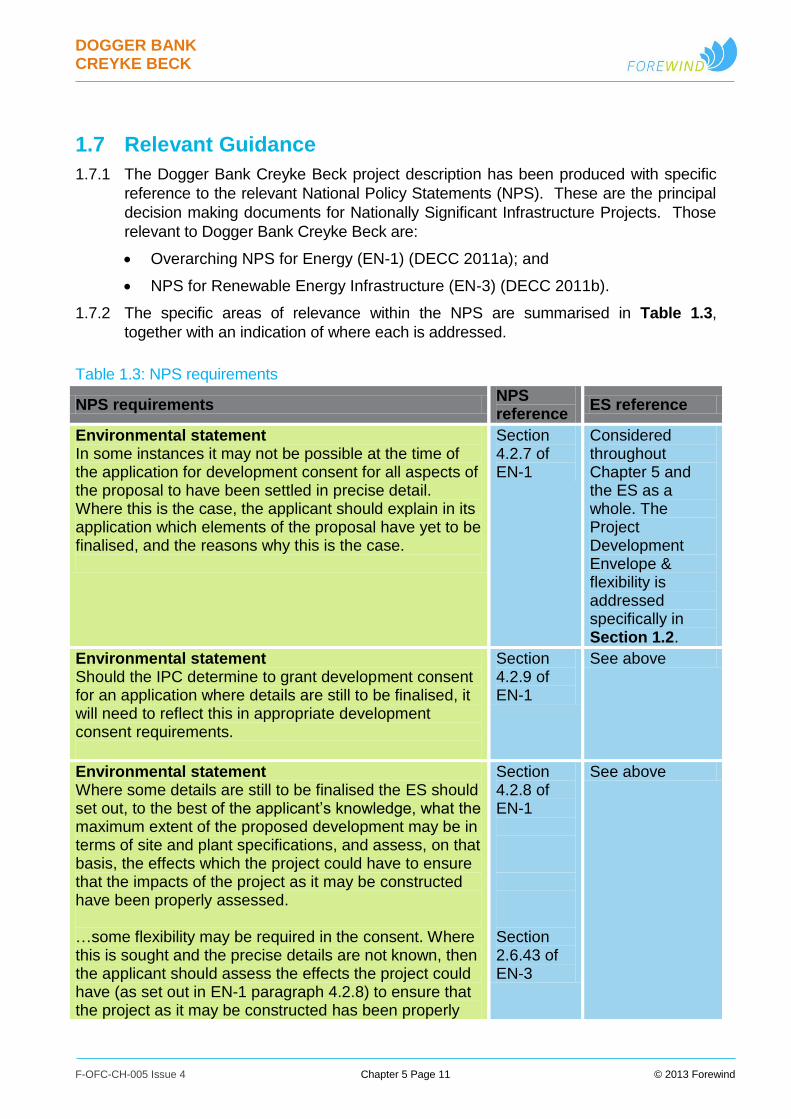
1.7 Relevant Guidance
1.7.1 The Dogger Bank Creyke Beck project description has been produced with specific
reference to the relevant National Policy Statements (NPS). These are the principal
decision making documents for Nationally Significant Infrastructure Projects. Those
relevant to Dogger Bank Creyke Beck are:
Overarching NPS for Energy (EN-1) (DECC 2011a); and
NPS for Renewable Energy Infrastructure (EN-3) (DECC 2011b).
1.7.2 The specific areas of relevance within the NPS are summarised in Table 1.3,
together with an indication of where each is addressed.
Table 1.3: NPS requirements
NPS requirements NPS reference
ES reference
Environmental statement In some instances it may not be possible at the time of the application for development consent for all aspects of the proposal to have been settled in precise detail. Where this is the case, the applicant should explain in its application which elements of the proposal have yet to be finalised, and the reasons why this is the case.
Section 4.2.7 of EN-1
Considered throughout Chapter 5 and the ES as a whole. The Project Development Envelope & flexibility is addressed specifically in Section 1.2.
Environmental statement Should the IPC determine to grant development consent for an application where details are still to be finalised, it will need to reflect this in appropriate development consent requirements.
Section 4.2.9 of EN-1
See above
Environmental statement Where some details are still to be finalised the ES should set out, to the best of the applicant’s knowledge, what the maximum extent of the proposed development may be in terms of site and plant specifications, and assess, on that basis, the effects which the project could have to ensure that the impacts of the project as it may be constructed have been properly assessed. …some flexibility may be required in the consent. Where this is sought and the precise details are not known, then the applicant should assess the effects the project could have (as set out in EN-1 paragraph 4.2.8) to ensure that the project as it may be constructed has been properly
Section 4.2.8 of EN-1 Section 2.6.43 of EN-3
See above
DOGGER BANK CREYKE BECK
F-OFC-CH-005 Issue 4 Chapter 5 Page 12 © 2013 Forewind
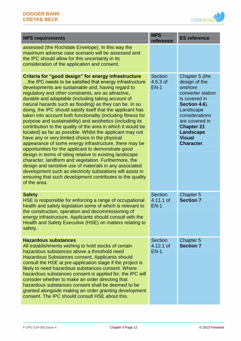
NPS requirements NPS reference
ES reference
assessed (the Rochdale Envelope). In this way the maximum adverse case scenario will be assessed and the IPC should allow for this uncertainty in its consideration of the application and consent.
Criteria for “good design” for energy infrastructure …the IPC needs to be satisfied that energy infrastructure developments are sustainable and, having regard to regulatory and other constraints, are as attractive, durable and adaptable (including taking account of natural hazards such as flooding) as they can be. In so doing, the IPC should satisfy itself that the applicant has taken into account both functionality (including fitness for purpose and sustainability) and aesthetics (including its contribution to the quality of the area in which it would be located) as far as possible. Whilst the applicant may not have any or very limited choice in the physical appearance of some energy infrastructure, there may be opportunities for the applicant to demonstrate good design in terms of siting relative to existing landscape character, landform and vegetation. Furthermore, the design and sensitive use of materials in any associated development such as electricity substations will assist in ensuring that such development contributes to the quality of the area.
Section 4.5.3 of EN-1
Chapter 5 (the design of the onshore converter station is covered in Section 4.6). Landscape considerations are covered in Chapter 21 Landscape Visual Character.
Safety HSE is responsible for enforcing a range of occupational health and safety legislation some of which is relevant to the construction, operation and decommissioning of energy infrastructure. Applicants should consult with the Health and Safety Executive (HSE) on matters relating to safety.
Section 4.11.1 of EN-1
Chapter 5 Section 7
Hazardous substances All establishments wishing to hold stocks of certain hazardous substances above a threshold need Hazardous Substances consent. Applicants should consult the HSE at pre-application stage if the project is likely to need hazardous substances consent. Where hazardous substances consent is applied for, the IPC will consider whether to make an order directing that hazardous substances consent shall be deemed to be granted alongside making an order granting development consent. The IPC should consult HSE about this.
Section 4.12.1 of EN-1
Chapter 5 Section 7

DOGGER BANK CREYKE BECK
F-OFC-CH-005 Issue 4 Chapter 5 Page 13 © 2013 Forewind
NPS requirements NPS reference
ES reference
Water depth and foundation conditions The onus is on the applicant to ensure that the foundation design is technically suitable for the seabed conditions and that the application caters for any uncertainty regarding the geological conditions.
Section 2.6.31 of EN-3
Chapter 5 Section 2.2 presents site information. Sections 3.2, 3.3, 3.5, and 3.6 present foundations and associated elements. Sections 6.2 and 6.3 discuss pre-construction and construction
Grid connection Applicants for consent for offshore wind farms will have to work within the regulatory regime for offshore transmission networks established by Ofgem. Under the regime offshore transmission will be a licensed activity regulated by Ofgem.
Section 2.6.34 of EN-3
Chapter 5 Section 1.3
Micrositing Any consent that is granted by the IPC should be flexible to allow for necessary micrositing of elements of the proposed wind farm during its construction where requested at the application stage. This allows for unforeseen events such as the discovery of previously unknown marine archaeology that it would be preferable to leave in situ. Where micrositing tolerance is requested by the applicant in any consent, given that the EIA should assess a maximum adverse case scenario, the assessment should reflect the implications of any micrositing as far as reasonably possible.
Sections 2.6.44 and 2.6.45 of EN-3
Chapter 5 Sections 5.1 and 5.4 acknowledge the potential for micrositing. The possible impacts are assessed in the relevant technical assessment chapters e.g. Chapter 12 Marine and Intertidal Ecology.
Repowering Where an operational offshore wind farm reaches the end of its life, subject to obtaining the necessary lease from The Crown Estate or providing an existing lease is still valid, the owner of the wind farm may wish to “repower” the site with new turbines. Given the likely change in technology over the intervening time period, any repowering of sites is likely to involve wind turbines of a different scale and nature. This could result in significantly different impacts as well as a different electricity generating capacity and a new consent application would be required.
Section 2.6.49 of EN-3
Repowering is discussed in Chapter 5 Section 6.6 under the heading “Replanting/ Life Extension”.
DOGGER BANK CREYKE BECK
F-OFC-CH-005 Issue 4 Chapter 5 Page 14 © 2013 Forewind
1.8 Consultation
1.8.1 As part of the development of Dogger Bank Creyke Beck, Forewind has undertaken
a thorough pre-application consultation process, which has included the following key
stages:
Scoping Report submitted to the Infrastructure Planning Commission (IPC)
(now the Planning Inspectorate) (October 2010);
Scoping Opinion received from the IPC (November 2010);
First stage of statutory consultation (in accordance with sections 42 and 47 of
the Planning Act 2008) on Preliminary Environmental Information (PEI) 1 (report
published November 2011); and
Second stage of statutory consultation (in accordance with sections 42, 47 and
48 of the Planning Act 2008) on the draft ES designed to allow for comments
before final application to the Planning Inspectorate.
1.8.2 In between the statutory consultation periods, Forewind consulted specific groups of
stakeholders on a non-statutory basis to ensure that they had an opportunity to
inform and influence the development proposals. Consultation undertaken
throughout the pre-application development phase has informed Forewind’s design
decision making and the information presented in this document. Further information
detailing the consultation process is presented in Chapter 7 Consultation. A
Consultation Report is also provided alongside this ES, as part of the overall planning
submission.
1.8.3 Table 1.4 highlights the key elements of the project design that have been influenced
by consultation carried out during the pre-application phase (statutory and non-
statutory), and indicates which sections of which chapter address each issue. This
table only includes the key items of consultation that have defined the assessment
and further detail around these issues (where relevant) can be found in the chapters
referenced in the final column. A considerable number of comments, issues and
concerns raised during consultation have been addressed during the pre-application
phase. Further details of how the consultation process has shaped the project
design are available in Chapter 6 Site Selection and Alternatives.

DOGGER BANK CREYKE BECK
F-OFC-CH-005 Issue 4 Chapter 5 Page 15 © 2013 Forewind
Table 1.4: Summary of key consultation and issues raised by consultees
Date and form of consultation
Consultee Summary of issue ES reference
November 2011 (first stage of statutory consultation) Non-statutory consultation between the first and second stages of statutory consultation (November 2011 to April 2013)
Various Various
The western edge of the developable area was identified as being environmentally sensitive, particularly due to the sandeel fishery and the associated seabird feeding activity. On account of this, the western edge of the developable area, and therefore the Dogger Bank Creyke Beck B project boundary, was moved to the east of the Shearwater Elgin Area Line (SEAL) pipeline.
Chapter 6 Site Selection and Alternatives Appendix 6A Offshore Project Boundary Selection Report, Section 2.4
June 2013 (section 42 consultation on the draft ES, statutory)
Joint Nature Conservation Committee (JNCC), Natural England, Royal Society for the Protection of Birds (RSPB)
Preliminary assessment work suggested potentially significant impacts on ornithology. In order to mitigate the impact associated with collision risk, the design envelope was refined to include:
A maximum number of 200 turbines per project (i.e. reduced by 33% from 300); and
An associated increase in the minimum lower blade tip height (from 22m to 26m) above highest astronomical tide.
This chapter, Section 3.1 Chapter 11 Marine and Coastal Ornithology
DOGGER BANK CREYKE BECK
F-OFC-CH-005 Issue 4 Chapter 5 Page 16 © 2013 Forewind
Date and form of consultation
Consultee Summary of issue ES reference
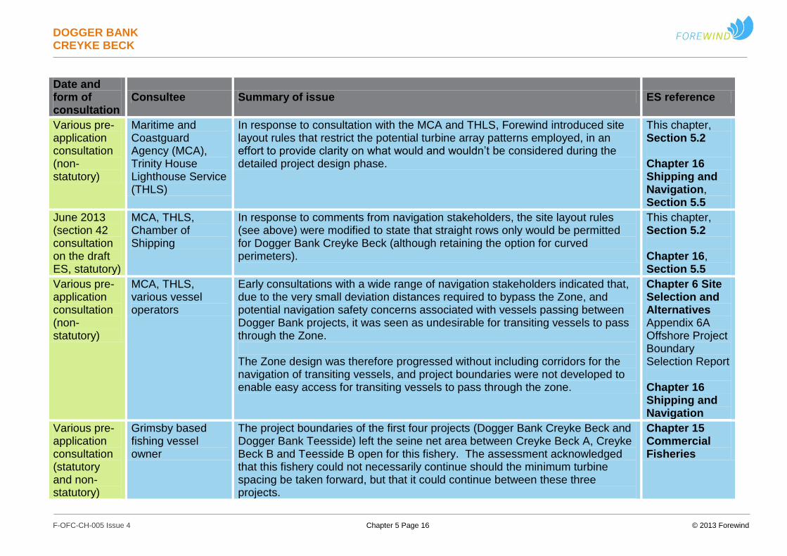
Various pre-application consultation (non-statutory)
Maritime and Coastguard Agency (MCA), Trinity House Lighthouse Service (THLS)
In response to consultation with the MCA and THLS, Forewind introduced site layout rules that restrict the potential turbine array patterns employed, in an effort to provide clarity on what would and wouldn’t be considered during the detailed project design phase.
This chapter, Section 5.2 Chapter 16 Shipping and Navigation, Section 5.5
June 2013 (section 42 consultation on the draft ES, statutory)
MCA, THLS, Chamber of Shipping
In response to comments from navigation stakeholders, the site layout rules (see above) were modified to state that straight rows only would be permitted for Dogger Bank Creyke Beck (although retaining the option for curved perimeters).
This chapter, Section 5.2 Chapter 16, Section 5.5
Various pre-application consultation (non-statutory)
MCA, THLS, various vessel operators
Early consultations with a wide range of navigation stakeholders indicated that, due to the very small deviation distances required to bypass the Zone, and potential navigation safety concerns associated with vessels passing between Dogger Bank projects, it was seen as undesirable for transiting vessels to pass through the Zone. The Zone design was therefore progressed without including corridors for the navigation of transiting vessels, and project boundaries were not developed to enable easy access for transiting vessels to pass through the zone.
Chapter 6 Site Selection and Alternatives Appendix 6A Offshore Project Boundary Selection Report Chapter 16 Shipping and Navigation
Various pre-application consultation (statutory and non-statutory)
Grimsby based fishing vessel owner
The project boundaries of the first four projects (Dogger Bank Creyke Beck and Dogger Bank Teesside) left the seine net area between Creyke Beck A, Creyke Beck B and Teesside B open for this fishery. The assessment acknowledged that this fishery could not necessarily continue should the minimum turbine spacing be taken forward, but that it could continue between these three projects.
Chapter 15 Commercial Fisheries
DOGGER BANK CREYKE BECK
F-OFC-CH-005 Issue 4 Chapter 5 Page 17 © 2013 Forewind
Date and form of consultation
Consultee Summary of issue ES reference
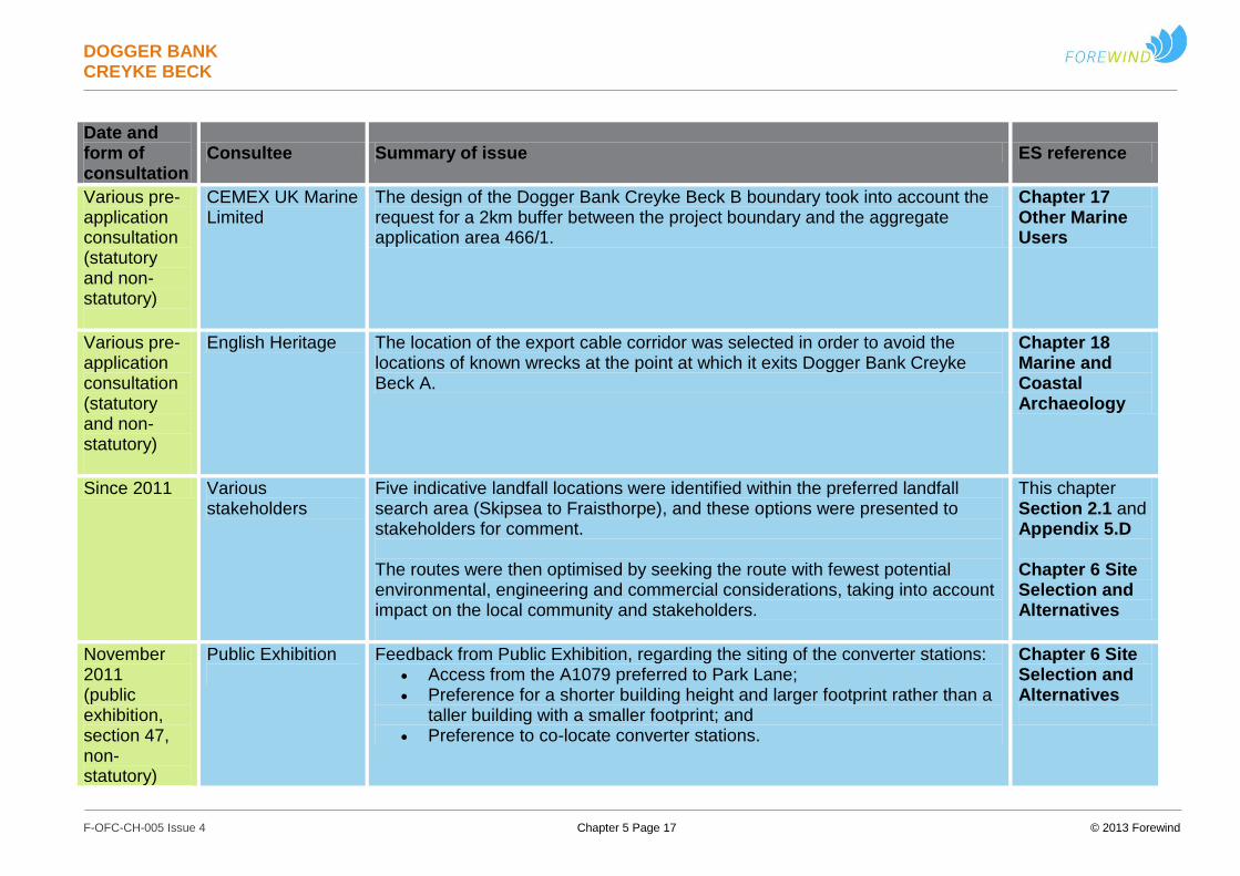
Various pre-application consultation (statutory and non-statutory)
CEMEX UK Marine Limited
The design of the Dogger Bank Creyke Beck B boundary took into account the request for a 2km buffer between the project boundary and the aggregate application area 466/1.
Chapter 17 Other Marine Users
Various pre-application consultation (statutory and non-statutory)
English Heritage The location of the export cable corridor was selected in order to avoid the locations of known wrecks at the point at which it exits Dogger Bank Creyke Beck A.
Chapter 18 Marine and Coastal Archaeology
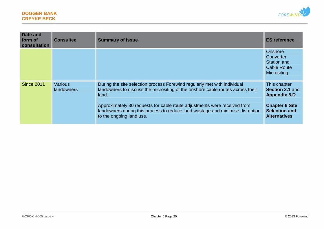
Since 2011 Various stakeholders
Five indicative landfall locations were identified within the preferred landfall search area (Skipsea to Fraisthorpe), and these options were presented to stakeholders for comment. The routes were then optimised by seeking the route with fewest potential environmental, engineering and commercial considerations, taking into account impact on the local community and stakeholders.
This chapter Section 2.1 and Appendix 5.D Chapter 6 Site Selection and Alternatives
November 2011 (public exhibition, section 47, non-statutory)
Public Exhibition
Feedback from Public Exhibition, regarding the siting of the converter stations: Access from the A1079 preferred to Park Lane; Preference for a shorter building height and larger footprint rather than a
taller building with a smaller footprint; and
Preference to co-locate converter stations.
Chapter 6 Site Selection and Alternatives
DOGGER BANK CREYKE BECK
F-OFC-CH-005 Issue 4 Chapter 5 Page 18 © 2013 Forewind
Date and form of consultation
Consultee Summary of issue ES reference
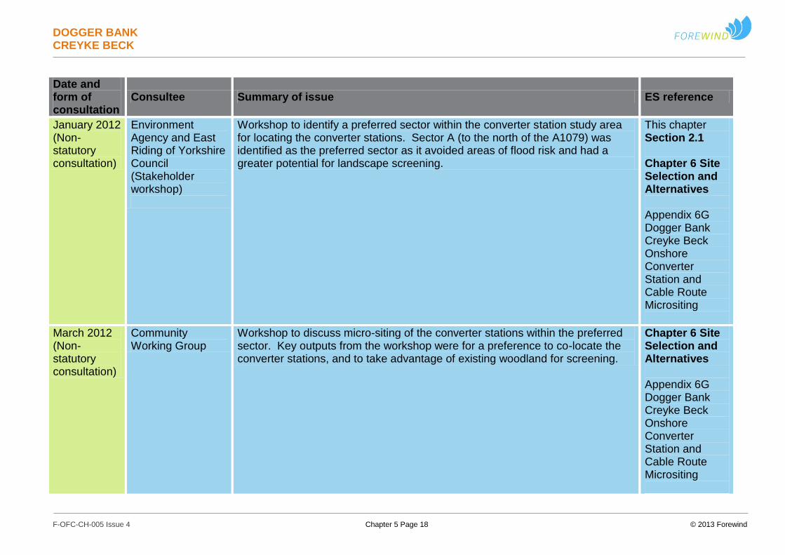
January 2012 (Non-statutory consultation)
Environment Agency and East Riding of Yorkshire Council (Stakeholder workshop)
Workshop to identify a preferred sector within the converter station study area for locating the converter stations. Sector A (to the north of the A1079) was identified as the preferred sector as it avoided areas of flood risk and had a greater potential for landscape screening.
This chapter Section 2.1 Chapter 6 Site Selection and Alternatives Appendix 6G Dogger Bank Creyke Beck Onshore Converter Station and Cable Route Micrositing
March 2012 (Non-statutory consultation)
Community Working Group
Workshop to discuss micro-siting of the converter stations within the preferred sector. Key outputs from the workshop were for a preference to co-locate the converter stations, and to take advantage of existing woodland for screening.
Chapter 6 Site Selection and Alternatives Appendix 6G Dogger Bank Creyke Beck Onshore Converter Station and Cable Route Micrositing
DOGGER BANK CREYKE BECK
F-OFC-CH-005 Issue 4 Chapter 5 Page 19 © 2013 Forewind
Date and form of consultation
Consultee Summary of issue ES reference
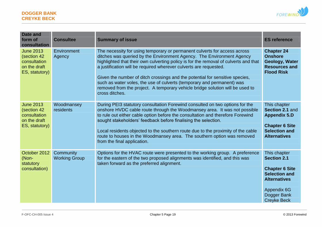
June 2013 (section 42 consultation on the draft ES, statutory)
Environment Agency
The necessity for using temporary or permanent culverts for access across ditches was queried by the Environment Agency. The Environment Agency highlighted that their own culverting policy is for the removal of culverts and that a justification will be required wherever culverts are requested. Given the number of ditch crossings and the potential for sensitive species, such as water voles, the use of culverts (temporary and permanent) was removed from the project. A temporary vehicle bridge solution will be used to cross ditches.
Chapter 24 Onshore Geology, Water Resources and Flood Risk
June 2013 (section 42 consultation on the draft ES, statutory)
Woodmansey residents
During PEI3 statutory consultation Forewind consulted on two options for the onshore HVDC cable route through the Woodmansey area. It was not possible to rule out either cable option before the consultation and therefore Forewind sought stakeholders’ feedback before finalising the selection. Local residents objected to the southern route due to the proximity of the cable route to houses in the Woodmansey area. The southern option was removed from the final application.
This chapter Section 2.1 and Appendix 5.D Chapter 6 Site Selection and Alternatives
October 2012 (Non-statutory consultation)
Community Working Group
Options for the HVAC route were presented to the working group. A preference for the eastern of the two proposed alignments was identified, and this was taken forward as the preferred alignment.
This chapter Section 2.1 Chapter 6 Site Selection and Alternatives Appendix 6G Dogger Bank Creyke Beck
DOGGER BANK CREYKE BECK
F-OFC-CH-005 Issue 4 Chapter 5 Page 20 © 2013 Forewind
Date and form of consultation
Consultee Summary of issue ES reference
Onshore Converter Station and Cable Route Micrositing
Since 2011 Various landowners
During the site selection process Forewind regularly met with individual landowners to discuss the micrositing of the onshore cable routes across their land. Approximately 30 requests for cable route adjustments were received from landowners during this process to reduce land wastage and minimise disruption to the ongoing land use.
This chapter Section 2.1 and Appendix 5.D Chapter 6 Site Selection and Alternatives
DOGGER BANK CREYKE BECK
F-OFC-CH-005 Issue 4 Chapter 5 Page 21 © 2013 Forewind
2 Site Description
2.1 Site Location
Dogger Bank Zone
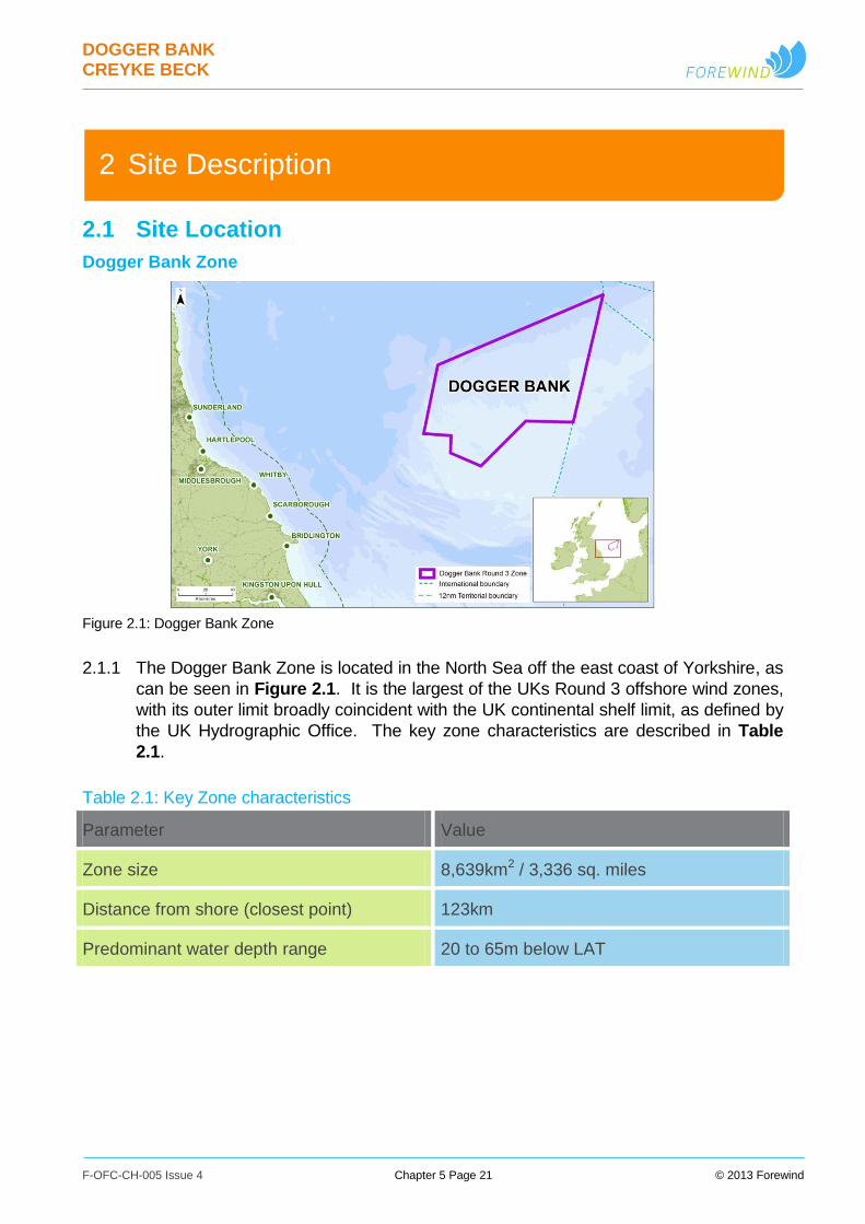
Figure 2.1: Dogger Bank Zone
2.1.1 The Dogger Bank Zone is located in the North Sea off the east coast of Yorkshire, as
can be seen in Figure 2.1. It is the largest of the UKs Round 3 offshore wind zones,
with its outer limit broadly coincident with the UK continental shelf limit, as defined by
the UK Hydrographic Office. The key zone characteristics are described in Table
2.1.
Table 2.1: Key Zone characteristics
Parameter Value
Zone size 8,639km2 / 3,336 sq. miles
Distance from shore (closest point) 123km
Predominant water depth range 20 to 65m below LAT
DOGGER BANK CREYKE BECK
F-OFC-CH-005 Issue 4 Chapter 5 Page 22 © 2013 Forewind
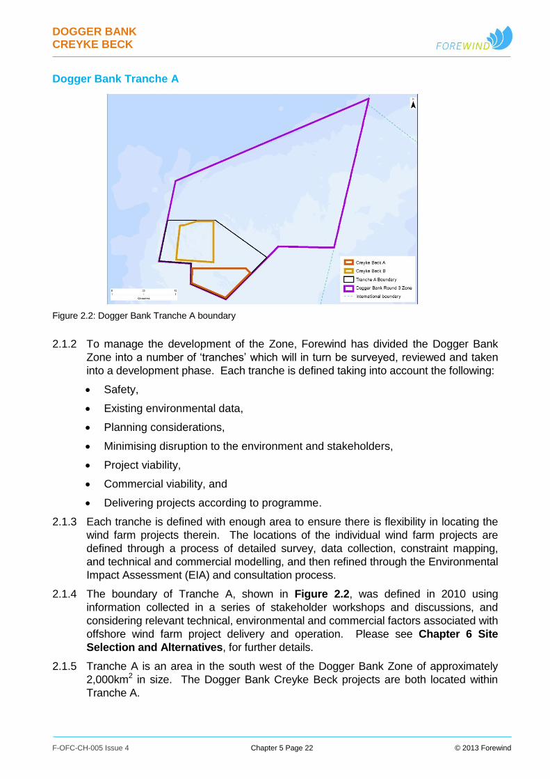
Dogger Bank Tranche A
Figure 2.2: Dogger Bank Tranche A boundary
2.1.2 To manage the development of the Zone, Forewind has divided the Dogger Bank
Zone into a number of ‘tranches’ which will in turn be surveyed, reviewed and taken
into a development phase. Each tranche is defined taking into account the following:
Safety,
Existing environmental data,
Planning considerations,
Minimising disruption to the environment and stakeholders,
Project viability,
Commercial viability, and
Delivering projects according to programme.
2.1.3 Each tranche is defined with enough area to ensure there is flexibility in locating the
wind farm projects therein. The locations of the individual wind farm projects are
defined through a process of detailed survey, data collection, constraint mapping,
and technical and commercial modelling, and then refined through the Environmental
Impact Assessment (EIA) and consultation process.
2.1.4 The boundary of Tranche A, shown in Figure 2.2, was defined in 2010 using
information collected in a series of stakeholder workshops and discussions, and
considering relevant technical, environmental and commercial factors associated with
offshore wind farm project delivery and operation. Please see Chapter 6 Site
Selection and Alternatives, for further details.
2.1.5 Tranche A is an area in the south west of the Dogger Bank Zone of approximately
2,000km2 in size. The Dogger Bank Creyke Beck projects are both located within
Tranche A.
DOGGER BANK CREYKE BECK
F-OFC-CH-005 Issue 4 Chapter 5 Page 23 © 2013 Forewind
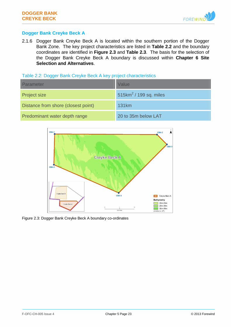
Dogger Bank Creyke Beck A
2.1.6 Dogger Bank Creyke Beck A is located within the southern portion of the Dogger
Bank Zone. The key project characteristics are listed in Table 2.2 and the boundary
coordinates are identified in Figure 2.3 and Table 2.3. The basis for the selection of
the Dogger Bank Creyke Beck A boundary is discussed within Chapter 6 Site
Selection and Alternatives.
Table 2.2: Dogger Bank Creyke Beck A key project characteristics
Parameter Value
Project size 515km2 / 199 sq. miles
Distance from shore (closest point) 131km
Predominant water depth range 20 to 35m below LAT
Figure 2.3: Dogger Bank Creyke Beck A boundary co-ordinates
DOGGER BANK CREYKE BECK
F-OFC-CH-005 Issue 4 Chapter 5 Page 24 © 2013 Forewind
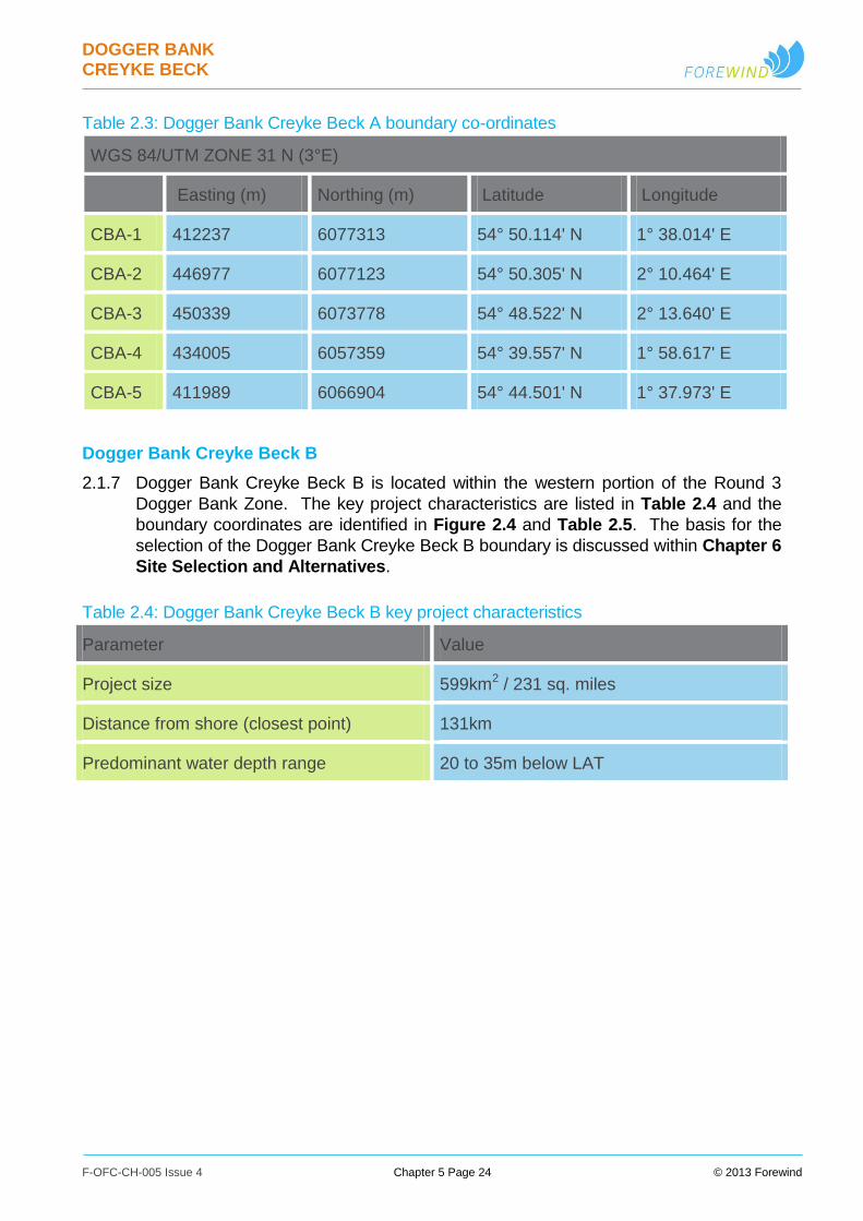
Table 2.3: Dogger Bank Creyke Beck A boundary co-ordinates
WGS 84/UTM ZONE 31 N (3°E)
Easting (m) Northing (m) Latitude Longitude
CBA-1 412237 6077313 54° 50.114' N 1° 38.014' E
CBA-2 446977 6077123 54° 50.305' N 2° 10.464' E
CBA-3 450339 6073778 54° 48.522' N 2° 13.640' E
CBA-4 434005 6057359 54° 39.557' N 1° 58.617' E
CBA-5 411989 6066904 54° 44.501' N 1° 37.973' E
Dogger Bank Creyke Beck B
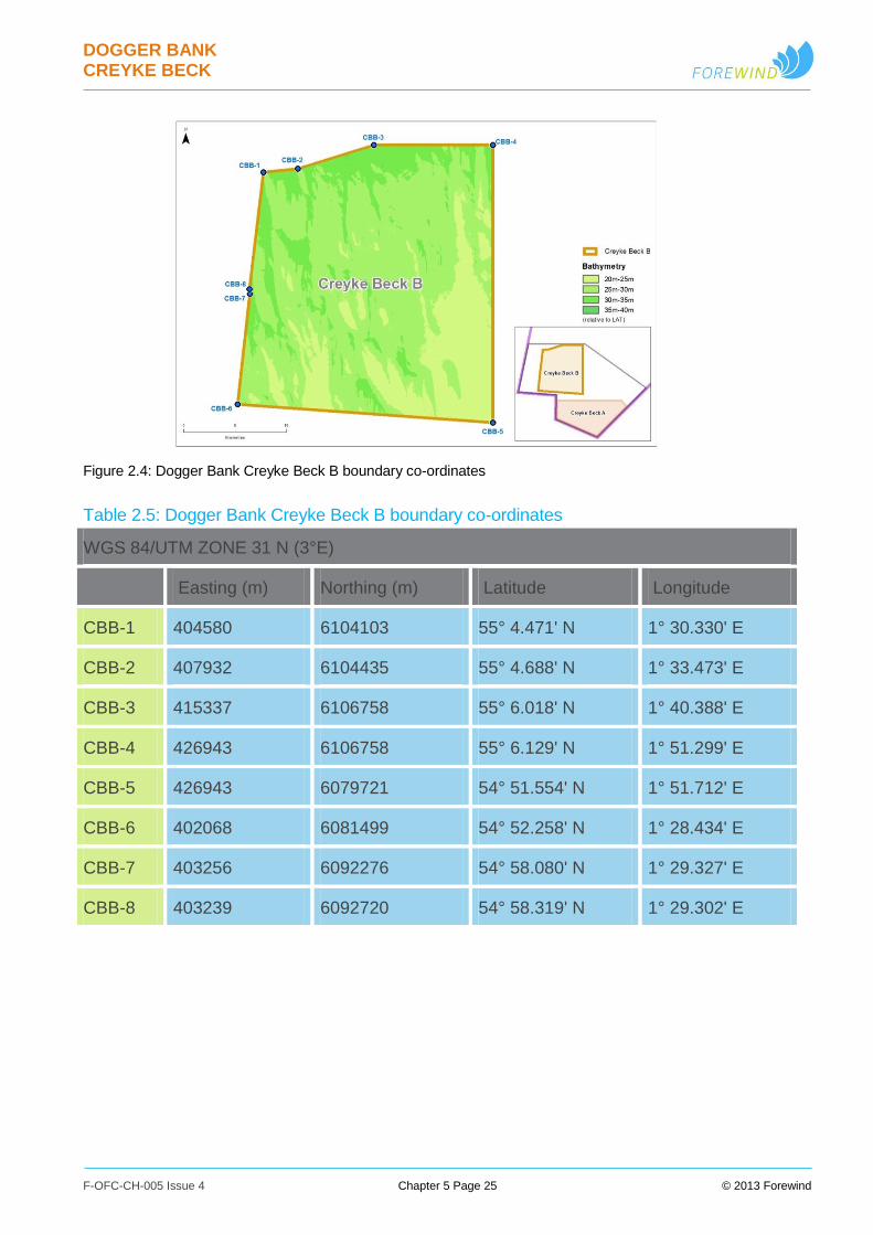
2.1.7 Dogger Bank Creyke Beck B is located within the western portion of the Round 3
Dogger Bank Zone. The key project characteristics are listed in Table 2.4 and the
boundary coordinates are identified in Figure 2.4 and Table 2.5. The basis for the
selection of the Dogger Bank Creyke Beck B boundary is discussed within Chapter 6
Site Selection and Alternatives.
Table 2.4: Dogger Bank Creyke Beck B key project characteristics
Parameter Value
Project size 599km2 / 231 sq. miles
Distance from shore (closest point) 131km
Predominant water depth range 20 to 35m below LAT
DOGGER BANK CREYKE BECK
F-OFC-CH-005 Issue 4 Chapter 5 Page 25 © 2013 Forewind
Figure 2.4: Dogger Bank Creyke Beck B boundary co-ordinates
Table 2.5: Dogger Bank Creyke Beck B boundary co-ordinates
WGS 84/UTM ZONE 31 N (3°E)
Easting (m) Northing (m) Latitude Longitude
CBB-1 404580 6104103 55° 4.471' N 1° 30.330' E
CBB-2 407932 6104435 55° 4.688' N 1° 33.473' E
CBB-3 415337 6106758 55° 6.018' N 1° 40.388' E
CBB-4 426943 6106758 55° 6.129' N 1° 51.299' E
CBB-5 426943 6079721 54° 51.554' N 1° 51.712' E
CBB-6 402068 6081499 54° 52.258' N 1° 28.434' E
CBB-7 403256 6092276 54° 58.080' N 1° 29.327' E
CBB-8 403239 6092720 54° 58.319' N 1° 29.302' E
DOGGER BANK CREYKE BECK
F-OFC-CH-005 Issue 4 Chapter 5 Page 26 © 2013 Forewind
Offshore Export Cable Corridor
2.1.8 The export cables for both the Dogger Bank Creyke Beck projects will be installed
within the corridor shown in Figure 2.5. The export cable corridor will stretch
predominantly north-east to south-west from the south-western corners of the
offshore project boundaries, to the cable landfall on the Holderness coastline, north
of Ulrome, in the East Riding of Yorkshire. A section of corridor also links Creyke
Beck A and B together. The basis for the selection of the export cable corridor
boundaries is discussed within Chapter 6 Site Selection and Alternatives.
2.1.9 The export cable corridor branches to include two potential exit points from the
Dogger Bank Zone. The two corridor branches, named “Creyke Beck Export
Corridor South” and “Creyke Beck Export Corridor North”, join at a distance of
approximately 19km from the zone boundary. The corridor exit points/branches may
be used by the two projects as follows:
Creyke Beck A export cables will use the southernmost exit point and will be
routed along Creyke Beck Export Corridor South;
Creyke Beck B cables may use either exit point and corridor branch, i.e. the
cables will be routed along either Creyke Beck Export Corridor South (via the
section of corridor linking Creyke Beck A and B, and then through Creyke Beck
A itself) or Creyke Beck Export Corridor North;
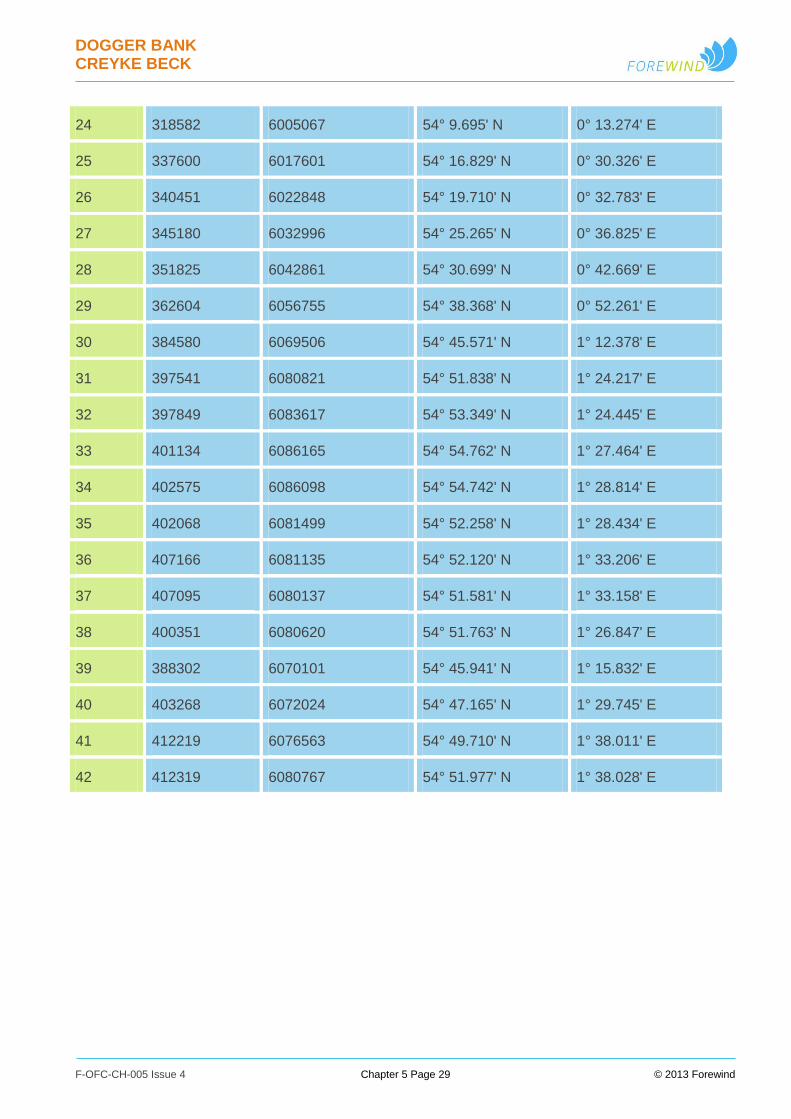
2.1.10 The offshore export cable corridor is generally 2km wide. The corridor widens slightly
in the near-shore area, before tapering into the landfall, and also widens in proximity
to the Creyke Beck offshore project boundaries. Table 2.6 provides a summary of
the export cable corridor coordinates.
2.1.11 Although the export cable corridors finish at the offshore project boundaries, the
offshore export cables themselves will actually run from the offshore converter
platforms (described in Section 3.7 Offshore Platforms) within the project
boundaries, to the landfall. The precise export cable routes, within the project areas
and export cable corridors, have not been finalised and will depend on the final wind
farm layout and converter platform locations, as well as detailed seabed geology and
environmental considerations.

DOGGER BANK CREYKE BECK
F-OFC-CH-005 Issue 4 Chapter 5 Page 27 © 2013 Forewind
Figure 2.5: The offshore export cable corridor

DOGGER BANK CREYKE BECK
F-OFC-CH-005 Issue 4 Chapter 5 Page 28 © 2013 Forewind
Table 2.6: Export cable corridor key co-ordinates (major vertices)
Easting (m) Northing (m) Latitude Longitude
1 421955 6080077 54° 51.701' N 1° 47.046' E
2 421955 6075512 54° 49.240' N 1° 47.120' E
3 414957 6073944 54° 48.326' N 1° 40.614' E
4 412157 6073964 54° 48.308' N 1° 38.001' E
5 412018 6068105 54° 45.149' N 1° 37.978' E
6 403268 6070008 54° 46.078' N 1° 29.785' E
7 385492 6067724 54° 44.622' N 1° 13.270' E
8 363909 6055215 54° 37.559' N 0° 53.516' E
9 353449 6041693 54° 30.098' N 0° 44.207' E
10 346902 6031974 54° 24.746' N 0° 38.448' E
11 342226 6021926 54° 19.247' N 0° 34.448' E
12 339110 6016191 54° 16.098' N 0° 31.762' E
13 319834 6003487 54° 8.870' N 0° 14.480' E
14 306622 5994386 54° 3.681' N 0° 2.709' E
15 303220 5992748 54° 2.722' N 0° 0.342' W
16 297321 5990454 54° 1.349' N 0° 5.648' W
17 293870 5989504 54° 0.756' N 0° 8.765' W
18 292300 5988927 54° 0.407' N 0° 10.177' W
19 289604 5988431 54° 0.075' N 0° 12.621' W
20 289437 5989299 54° 0.538' N 0° 12.809' W
21 290163 5991586 54° 1.787' N 0° 12.240' W
22 296729 5992734 54° 2.563' N 0° 6.281' W
23 305603 5996113 54° 4.588' N 0° 1.710' E
DOGGER BANK CREYKE BECK
F-OFC-CH-005 Issue 4 Chapter 5 Page 29 © 2013 Forewind
24 318582 6005067 54° 9.695' N 0° 13.274' E
25 337600 6017601 54° 16.829' N 0° 30.326' E
26 340451 6022848 54° 19.710' N 0° 32.783' E
27 345180 6032996 54° 25.265' N 0° 36.825' E
28 351825 6042861 54° 30.699' N 0° 42.669' E
29 362604 6056755 54° 38.368' N 0° 52.261' E
30 384580 6069506 54° 45.571' N 1° 12.378' E
31 397541 6080821 54° 51.838' N 1° 24.217' E
32 397849 6083617 54° 53.349' N 1° 24.445' E
33 401134 6086165 54° 54.762' N 1° 27.464' E
34 402575 6086098 54° 54.742' N 1° 28.814' E
35 402068 6081499 54° 52.258' N 1° 28.434' E
36 407166 6081135 54° 52.120' N 1° 33.206' E
37 407095 6080137 54° 51.581' N 1° 33.158' E
38 400351 6080620 54° 51.763' N 1° 26.847' E
39 388302 6070101 54° 45.941' N 1° 15.832' E
40 403268 6072024 54° 47.165' N 1° 29.745' E
41 412219 6076563 54° 49.710' N 1° 38.011' E
42 412319 6080767 54° 51.977' N 1° 38.028' E
DOGGER BANK CREYKE BECK
F-OFC-CH-005 Issue 4 Chapter 5 Page 30 © 2013 Forewind
Offshore Temporary Work Areas
2.1.12 A need for temporary work areas has been identified for use during construction,
within which vessels may carry out temporary intrusive activities such as deploying
anchors or jack-up legs as part of the construction process. These activities could
include cable installation vessels working alongside the defined cable corridors, and
construction vessels working near or outside the edge of the wind farm array
boundaries. The temporary work areas are shown within Figure 2.6, and their
dimensions are stated in Table 2.7.
Table 2.7: Temporary work area dimensions
Parameter Value
Width of temporary work area outside
export cable corridor (m)
750
Width of temporary work area outside
offshore project boundary (m)
1000
Offshore Boundary Overview
2.1.13 Figure 2.6 shows an overview of the boundaries of the offshore project elements
described within this document. Included within this figure are:
The Dogger Bank Creyke Beck A and B offshore project boundaries.
The offshore end of the offshore export cable corridors.
Temporary work areas.

DOGGER BANK CREYKE BECK
F-OFC-CH-005 Issue 4 Chapter 5 Page 31 © 2013 Forewind
Figure 2.6: Overview of offshore boundaries

DOGGER BANK CREYKE BECK
F-OFC-CH-005 Issue 4 Chapter 5 Page 32 © 2013 Forewind
Onshore Cable Landfall, Corridor & Route
2.1.14 The cable landfall is an area along the Holderness coastline, north of Ulrome, where
the joint transition bay is located and the offshore export cables come ashore. From
the landfall, the underground HVDC export cable corridor will continue onshore to the
proposed Dogger Bank Creyke Beck converter stations. From the converter stations,
underground HVAC cables will transmit the electricity the short distance to the
connection points at the nearby existing National Grid Creyke Beck substation, south
of Beverley. The basis for the selection of the cable corridor boundaries is discussed
within Chapter 6 Site Selection and Alternatives.
2.1.15 The onshore export cable corridor is indicatively 1km wide, and forms the area within
which cable route selection and surveys have taken place. An overview of the
onshore export cable corridor is shown in Figure 2.7.
2.1.16 Within the cable corridor, the cable route, and items such as the temporary works
compounds, temporary horizontal directional drilling (HDD) compounds, the landfall
transition joint bays, and access routes onto the construction working width have all
been located. The cable route encompasses the HVDC and HVAC cable systems,
and related construction working width. The cable route will consist of an
approximately 30km HVDC section and an approximately 2km HVAC section. The
cable route is 36m wide for the HVDC sections, and 38m wide for the HVAC
sections. The below-ground sections of the cable route at major HDD operations
may be up to 53m wide, or up to 70m in the case of the HDD below Figham
Pastures, and up to 250m wide below-ground at the landfall HDD.
2.1.17 The onshore cable route is shown in greater detail within Appendix 5.D Onshore
Cable Route Plan. This appendix includes indicative crossing points and
information, with further detailed information available in Chapter 24 Geology, Water
Resources and Land Quality.
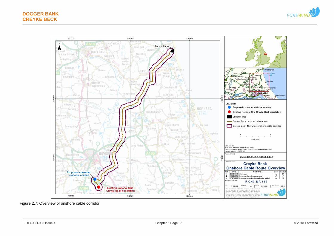
DOGGER BANK CREYKE BECK
F-OFC-CH-005 Issue 4 Chapter 5 Page 33 © 2013 Forewind
Figure 2.7: Overview of onshore cable corridor

DOGGER BANK CREYKE BECK
F-OFC-CH-005 Issue 4 Chapter 5 Page 34 © 2013 Forewind
Onshore Converter Station Sites
2.1.18 The new Dogger Bank Creyke Beck converter stations will be constructed within an
agricultural area located approximately 3km to the north-north west of the existing
National Grid Creyke Beck substation, approximately 4.5km south of Beverley, and
around 3.2km north of Cottingham. The converter stations site is located to the north
of the A1079. Indicative plans of the proposed layout are shown in Figure 2.8. The
basis for the selection of the converter station site is discussed within Chapter 6 Site
Selection and Alternatives.
2.1.19 It is proposed that two converter stations will be built, one for each of the Creyke
Beck projects. The two converter stations will be required for the conversion of the
electricity transmitted by the HVDC export cable into HVAC before connection to the
existing National Grid HVAC substation at Creyke Beck. The location of the onshore
converter station, in context with the full HVDC and HVAC cable routes, and the
existing National Grid substation, is shown within Appendix 5.D Onshore Cable
Route Plan.

DOGGER BANK CREYKE BECK
F-OFC-CH-005 Issue 4 Chapter 5 Page 35 © 2013 Forewind
Figure 2.8: Proposed Converter Stations Location

DOGGER BANK CREYKE BECK
F-OFC-CH-005 Issue 4 Chapter 5 Page 36 © 2013 Forewind
2.2 Offshore Site Description
Overview
2.2.1 Forewind has gathered a significant amount of information on the physical
environment of the Dogger Bank Zone. The survey programme has included
detailed geophysical (seabed and sub-seabed) surveys, geotechnical testing
(boreholes and cone penetration tests), meteorological and oceanographic data
collection via wave buoys and acoustic doppler current profilers (ADCPs), and wind
data collection using lidar and a tall meteorological mast. Data gathering across the
Zone is ongoing, but the data which formed an input into the environmental
assessments included approximately:
45 boreholes (including sampling and wireline logging);
100 cone penetration tests;
25,000 line kilometres of seabed and geophysical survey data;
100 seabed grab samples;
100 seabed camera survey locations;
3 wave buoys deployed;
2 ADCPs deployed; and
1 tide gauge deployed.
2.2.2 These data have been analysed with help from a number of expert consultants and
groups including the British Geological Survey, the Norwegian Geotechnical Institute,
RPS Energy and Royal HaskoningDHV.
2.2.3 Information on site bathymetry, waves, tidal currents, tidal range, geology and
seabed sediments are all contained within Chapter 9 Marine Physical Processes.
2.2.4 The current level of information is sufficiently detailed for the purposes of the
environmental assessment, however additional high resolution survey data will need
to be obtained to enable tasks such as detailed foundation design and cable burial
assessment to be undertaken. These surveys will be undertaken post-consent.
Wind Climate
2.2.5 The following indicative annual wind rose, Figure 2.9, shows the average wind speed
and direction for a representative location within Tranche A. In comparison to the
typical wind conditions across the UK as a whole, the Dogger Bank Zone can be
characterised as having very high average annual wind speeds.
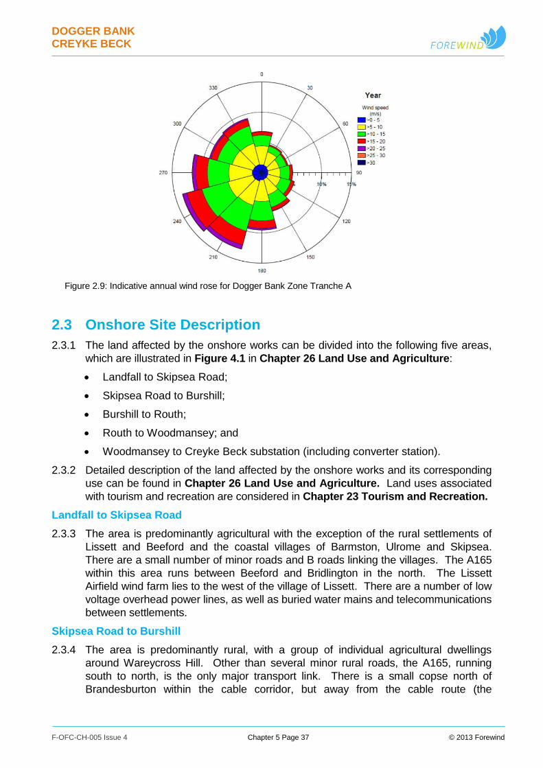
DOGGER BANK CREYKE BECK
F-OFC-CH-005 Issue 4 Chapter 5 Page 37 © 2013 Forewind
Figure 2.9: Indicative annual wind rose for Dogger Bank Zone Tranche A
2.3 Onshore Site Description
2.3.1 The land affected by the onshore works can be divided into the following five areas,
which are illustrated in Figure 4.1 in Chapter 26 Land Use and Agriculture:
Landfall to Skipsea Road;
Skipsea Road to Burshill;
Burshill to Routh;
Routh to Woodmansey; and
Woodmansey to Creyke Beck substation (including converter station).
2.3.2 Detailed description of the land affected by the onshore works and its corresponding
use can be found in Chapter 26 Land Use and Agriculture. Land uses associated
with tourism and recreation are considered in Chapter 23 Tourism and Recreation.
Landfall to Skipsea Road
2.3.3 The area is predominantly agricultural with the exception of the rural settlements of
Lissett and Beeford and the coastal villages of Barmston, Ulrome and Skipsea.
There are a small number of minor roads and B roads linking the villages. The A165
within this area runs between Beeford and Bridlington in the north. The Lissett
Airfield wind farm lies to the west of the village of Lissett. There are a number of low
voltage overhead power lines, as well as buried water mains and telecommunications
between settlements.
Skipsea Road to Burshill
2.3.4 The area is predominantly rural, with a group of individual agricultural dwellings
around Wareycross Hill. Other than several minor rural roads, the A165, running
south to north, is the only major transport link. There is a small copse north of
Brandesburton within the cable corridor, but away from the cable route (the
DOGGER BANK CREYKE BECK
F-OFC-CH-005 Issue 4 Chapter 5 Page 38 © 2013 Forewind
contruction working width) itself. Brandesburton Lakes lie towards the south of this
section of the study area. These are deep lakes, which the cable corridor avoids.
The only utilities present are water mains buried below the few roads present in this
area.
Burshill to Routh
2.3.5 This stretch of the proposed cable corridor is principally rural in nature, it is flat, and
the agricultural landscape is broken up by Brandesburton Pits to the north, the Leven
Canal and the village of Tickton to the south. The area is low lying with a large
number of agricultural ditches and ponds. Brandesburton and Leven to the east and
Tickton to the south are the only villages in the wider area. There are a number of
small areas of woodland present in particular a linear feature to the south of the
Leven Canal, which is itself designated a SSSI. The consented Hall Farm Wind
Farm lies south of the Leven Canal, it will consist of 12 wind turbines and
construction commenced in 2012. The following utilities are present: two water
mains, one high voltage overhead electricity transmission line and fibre optic cables
between the villages of Tickton and Routh.
Routh to Woodmansey
2.3.6 The cable corridor between Routh and Woodmansey is rural in character, comprising
mainly arable farmland with a number of associated properties. The A1035 is the
only main road crossed by the HVDC cable route within this section. The route also
crosses the River Hull and the Beverley and Barmston Drain. There is also a fishing
lake between the two watercourses. The following utilities are present along this
section of the cable route: two water mains, three fibre optic cables, and two high
pressure gas pipelines.
Woodmansey to Existing National Grid Substation at Creyke Beck
2.3.7 This section of the cable corridor, whilst still rural in character, has been influenced
by human activities to a greater extent. There are commercial properties and a
number of large horticultural operations indicated by greenhouse complexes. The
village of Woodmansey lies in a linear form either side of the A1174. Cottingham, on
the outskirts of Kingston upon Hull lies to the south of the existing Creyke Beck
substation. In addition to the A1174, the cable route crosses the A1079 and Hull to
Bridlington Railway line in this section. The route crosses the Beverley and
Barmston Drain to the west of the River Hull and there is also a fishing lake
immediately south, outside of the cable corridor. There are locally designated sites
within this area including, for example, Beverley Parks Local Nature Reserve and
three areas of ancient woodland.
2.3.8 At the existing National Grid substation at Creyke Beck the cable corridor will take
into account the presence of various assets related to the substation. There are
several overhead electricity transmission lines converging on the substation,
including 400kV and 275kV overhead lines. In the proximity of the substation area
there are also distribution overhead lines potentially crossing and/or running near the
projects’ cable corridors. In addition to these the corridor crosses two sewage mains,
two water mains, two fibre optic cables and two high pressure gas pipelines.

DOGGER BANK CREYKE BECK
F-OFC-CH-005 Issue 4 Chapter 5 Page 39 © 2013 Forewind
Land Use
2.3.9 The main land use within the East Riding of Yorkshire is agriculture and associated
rural dwellings and villages. This is considered in detail within Chapter 26 Land Use
and Agriculture. Land uses associated with tourism and recreation are considered
in more detail in Chapter 23 Tourism and Recreation.
2.3.10 In addition to the arable areas there are areas of grassland with a combination of
improved, neutral, rough and heather types. Areas of hardstanding and broadleaved
woodland are also present. The exceptions to this are as follows:
The land cover at the coast is described as littoral rock and sediment;
Ulrome, Woodmansey and small areas around the existing National Grid
substation at Creyke Beck are described as suburban;
The freshwater lakes at Brandesburton;
A large number of water features, mainly agricultural ditches, but also the Leven
Canal;
The River Hull and the Beverley and Barmston Drain; and
Areas described as hardstanding, glasshouses and grassland surrounding the
existing National Grid substation at Creyke Beck.
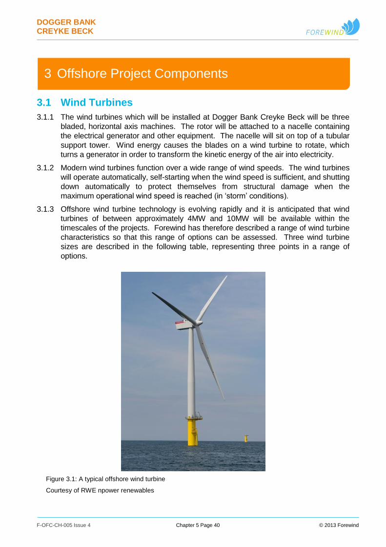
DOGGER BANK CREYKE BECK
F-OFC-CH-005 Issue 4 Chapter 5 Page 40 © 2013 Forewind
3 Offshore Project Components
3.1 Wind Turbines
3.1.1 The wind turbines which will be installed at Dogger Bank Creyke Beck will be three
bladed, horizontal axis machines. The rotor will be attached to a nacelle containing
the electrical generator and other equipment. The nacelle will sit on top of a tubular
support tower. Wind energy causes the blades on a wind turbine to rotate, which
turns a generator in order to transform the kinetic energy of the air into electricity.
3.1.2 Modern wind turbines function over a wide range of wind speeds. The wind turbines
will operate automatically, self-starting when the wind speed is sufficient, and shutting
down automatically to protect themselves from structural damage when the
maximum operational wind speed is reached (in ‘storm’ conditions).
3.1.3 Offshore wind turbine technology is evolving rapidly and it is anticipated that wind
turbines of between approximately 4MW and 10MW will be available within the
timescales of the projects. Forewind has therefore described a range of wind turbine
characteristics so that this range of options can be assessed. Three wind turbine
sizes are described in the following table, representing three points in a range of
options.
Figure 3.1: A typical offshore wind turbine
Courtesy of RWE npower renewables
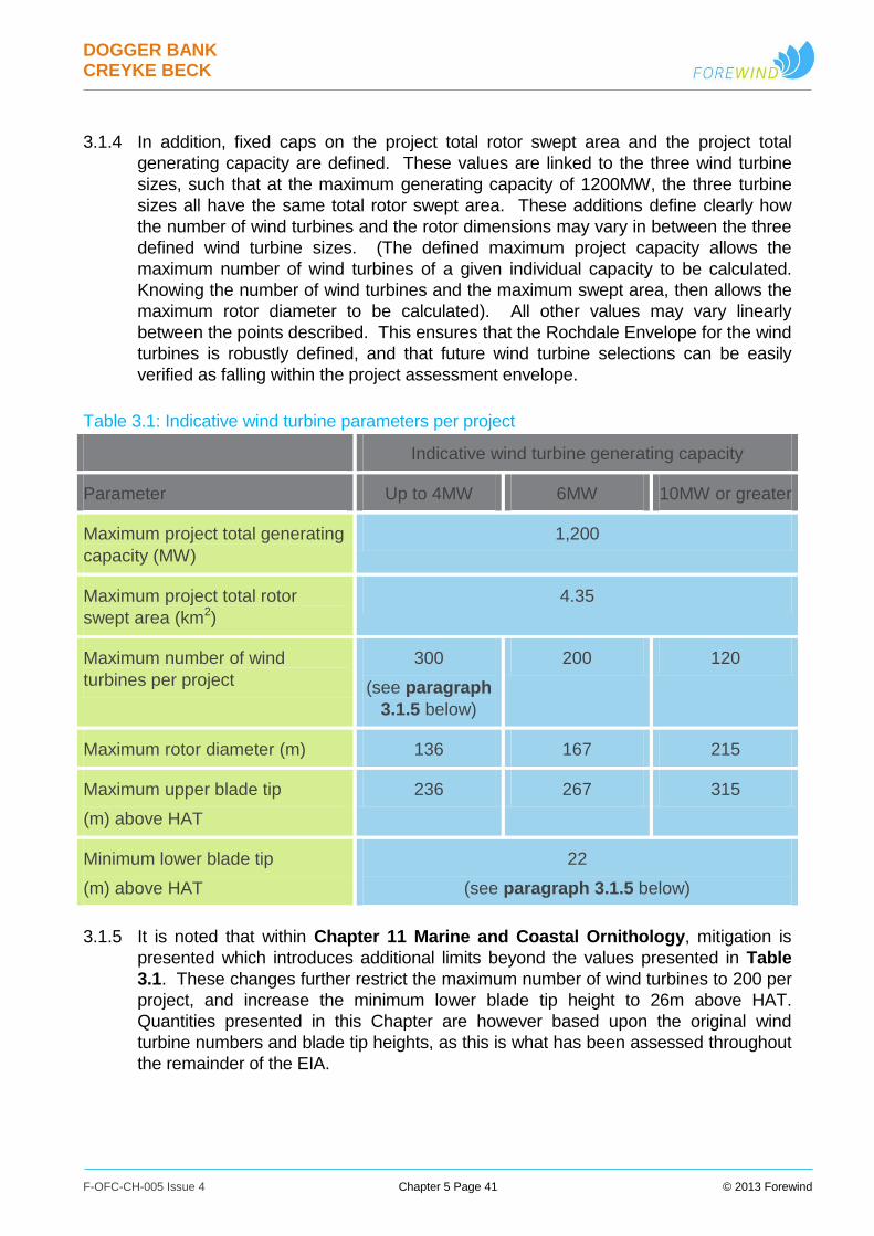
DOGGER BANK CREYKE BECK
F-OFC-CH-005 Issue 4 Chapter 5 Page 41 © 2013 Forewind
3.1.4 In addition, fixed caps on the project total rotor swept area and the project total
generating capacity are defined. These values are linked to the three wind turbine
sizes, such that at the maximum generating capacity of 1200MW, the three turbine
sizes all have the same total rotor swept area. These additions define clearly how
the number of wind turbines and the rotor dimensions may vary in between the three
defined wind turbine sizes. (The defined maximum project capacity allows the
maximum number of wind turbines of a given individual capacity to be calculated.
Knowing the number of wind turbines and the maximum swept area, then allows the
maximum rotor diameter to be calculated). All other values may vary linearly
between the points described. This ensures that the Rochdale Envelope for the wind
turbines is robustly defined, and that future wind turbine selections can be easily
verified as falling within the project assessment envelope.
Table 3.1: Indicative wind turbine parameters per project
Indicative wind turbine generating capacity
Parameter Up to 4MW 6MW 10MW or greater
Maximum project total generating
capacity (MW)
1,200
Maximum project total rotor
swept area (km2)
4.35
Maximum number of wind
turbines per project
300
(see paragraph
3.1.5 below)
200 120
Maximum rotor diameter (m) 136 167 215
Maximum upper blade tip
(m) above HAT
236 267 315
Minimum lower blade tip
(m) above HAT
22
(see paragraph 3.1.5 below)
3.1.5 It is noted that within Chapter 11 Marine and Coastal Ornithology, mitigation is
presented which introduces additional limits beyond the values presented in Table
3.1. These changes further restrict the maximum number of wind turbines to 200 per
project, and increase the minimum lower blade tip height to 26m above HAT.
Quantities presented in this Chapter are however based upon the original wind
turbine numbers and blade tip heights, as this is what has been assessed throughout
the remainder of the EIA.

DOGGER BANK CREYKE BECK
F-OFC-CH-005 Issue 4 Chapter 5 Page 42 © 2013 Forewind
3.1.6 The wind turbine options detailed in Table 3.1 are defined such that:
The values in the table define the range of values considered within the
environmental impact assessment. For example lower blade tip may vary from
the stated minimum of 22m above HAT, up to a height defined by the stated
maximum upper tip height and the selected wind turbine rotor diameter;
The values provided for the up to 4MW wind turbine represent the realistic worst
case for wind turbines of any size up to 4MW. 3.75MW wind turbines could
therefore be used, for example, but no more than 300 could be installed
(providing for a 1125MW generating capacity);
The values for the 6MW wind turbine are included to provide an example point
within the range described;
The values for the 10MW or greater wind turbine represent the realistic worst
case for wind turbines of 10MW or greater generating capacity. 15MW wind
turbines could therefore be used, for example, but the dimensions would not be
permitted to exceed the values considered within the assessment envelope
(e.g. a maximum rotor diameter of 215m), and only 80 units would be required
to provide the 1200MW maximum generating capacity;
Scenarios in which less than the maximum generating capacity is installed
introduce the possibility of a specific exception, which is that wind turbines with
unusually large dimensions could be accommodated within the assessment
envelope as long as the installed generating capacity was reduced to match the
proportionally largest of the dimensions. For example if a 6MW wind turbine
was produced with a 215m rotor diameter, the rotor would then correspond to
the defined 10MW wind turbine limit. This would still be within the assessment
envelope as long as only 120 were installed (a maximum installed generating
capacity of 720MW) and none of its dimensions exceed the 10MW or greater
absolute maximum values.
3.1.7 Shown in Figure 3.2, Figure 3.3, and Figure 3.4 are illustrations of key assessed
parameters for the up to 4MW, 6MW and 10MW or greater wind turbines. As
discussed in paragraph 3.1.5 above, it is noted that within Chapter 11 Marine and
Coastal Ornithology, mitigation is presented which introduces additional limits
beyond those illustrated in Figures 3.2 to 3.4. Specifically, this mitigation further
restricts the minimum lower blade tip height for all wind turbines to 26m above HAT.
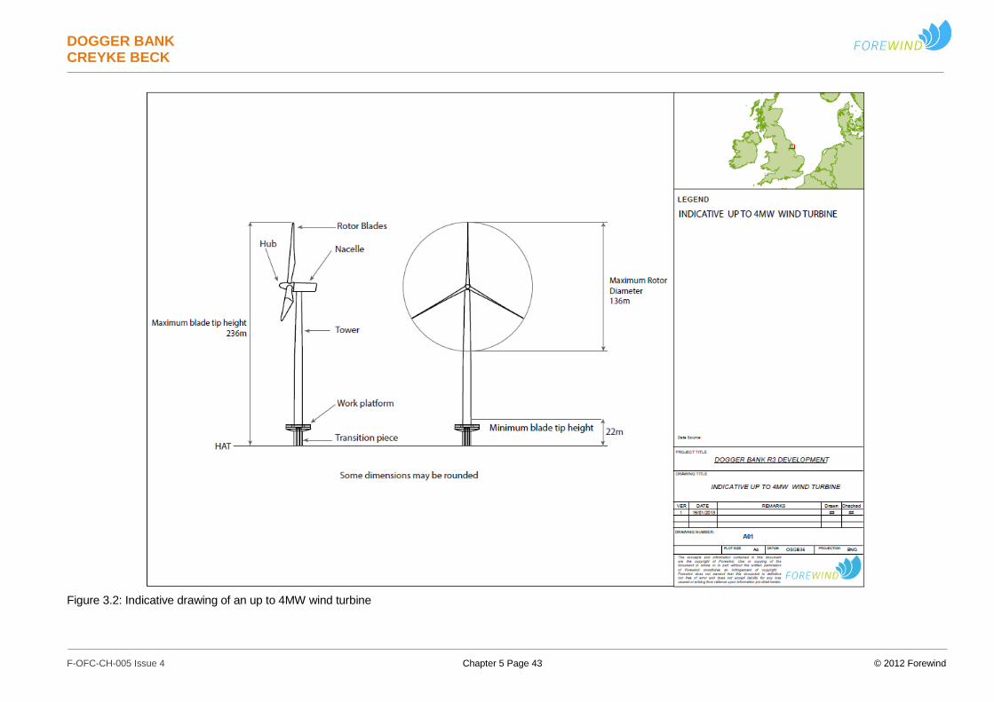
DOGGER BANK CREYKE BECK
F-OFC-CH-005 Issue 4 Chapter 5 Page 43 © 2012 Forewind
Figure 3.2: Indicative drawing of an up to 4MW wind turbine
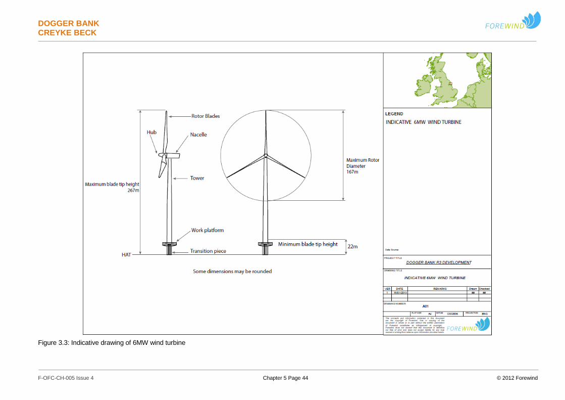
DOGGER BANK CREYKE BECK
F-OFC-CH-005 Issue 4 Chapter 5 Page 44 © 2012 Forewind
Figure 3.3: Indicative drawing of 6MW wind turbine
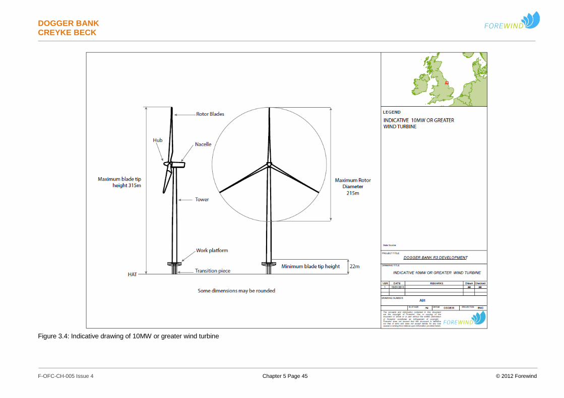
DOGGER BANK CREYKE BECK
F-OFC-CH-005 Issue 4 Chapter 5 Page 45 © 2012 Forewind
Figure 3.4: Indicative drawing of 10MW or greater wind turbine
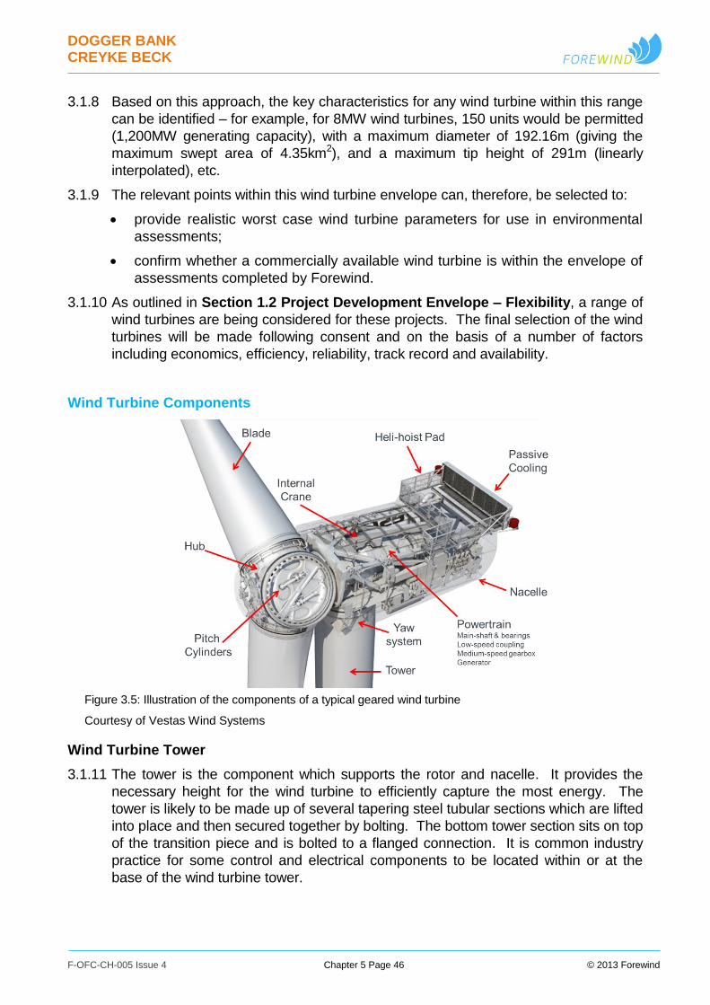
DOGGER BANK CREYKE BECK
F-OFC-CH-005 Issue 4 Chapter 5 Page 46 © 2013 Forewind
3.1.8 Based on this approach, the key characteristics for any wind turbine within this range
can be identified – for example, for 8MW wind turbines, 150 units would be permitted
(1,200MW generating capacity), with a maximum diameter of 192.16m (giving the
maximum swept area of 4.35km2), and a maximum tip height of 291m (linearly
interpolated), etc.
3.1.9 The relevant points within this wind turbine envelope can, therefore, be selected to:
provide realistic worst case wind turbine parameters for use in environmental
assessments;
confirm whether a commercially available wind turbine is within the envelope of
assessments completed by Forewind.
3.1.10 As outlined in Section 1.2 Project Development Envelope – Flexibility, a range of
wind turbines are being considered for these projects. The final selection of the wind
turbines will be made following consent and on the basis of a number of factors
including economics, efficiency, reliability, track record and availability.
Wind Turbine Components
Figure 3.5: Illustration of the components of a typical geared wind turbine
Courtesy of Vestas Wind Systems
Wind Turbine Tower
3.1.11 The tower is the component which supports the rotor and nacelle. It provides the
necessary height for the wind turbine to efficiently capture the most energy. The
tower is likely to be made up of several tapering steel tubular sections which are lifted
into place and then secured together by bolting. The bottom tower section sits on top
of the transition piece and is bolted to a flanged connection. It is common industry
practice for some control and electrical components to be located within or at the
base of the wind turbine tower.
DOGGER BANK CREYKE BECK
F-OFC-CH-005 Issue 4 Chapter 5 Page 47 © 2013 Forewind
Nacelle
3.1.12 The nacelle houses the electro-mechanical components of the wind turbine. There
may also be other equipment in the nacelle such as transformers, yaw systems, and
gearboxes. Some wind turbines include a fixed or dismountable crane, which can be
used to move components within the nacelle and/or down to the tower base to aid
maintenance activities. The nacelle may also be fitted with a helicopter access
winching platform to allow technicians and potentially rescue personnel to access the
wind turbine directly by helicopter.
Rotor
3.1.13 The rotor, comprising the three blades and the hub, is the device which extracts
energy from the wind and converts it into rotational motion. Increasing the blade
length allows more energy to be extracted from the passing wind. The pitch of the
blades can be adjusted by feathering or angling them, in order to control the rotation
speed of the rotor.
Wind Turbine Colouring
3.1.14 Wind turbines are typically supplied in a small range of standard colours. Offshore
wind turbines installed in the UK to date are commonly light grey (although they vary
in appearance, depending on the lighting conditions, between white and grey), and it
is assumed that Dogger Bank Creyke Beck wind turbines would follow this approach
and be coloured predominantly either white or light grey. In addition contrasting
colours are required on areas of the wind turbines and foundations. Some key
examples are listed below, but contrasting colours and alternative higher-visibility
colour schemes may be added if required for purposes such as hazard warnings, and
increasing the visibility of the wind turbines for various aspects of collision avoidance.
3.1.15 Contrasting colours are currently most commonly required in navigation and aviation
safety markings; described further in Section 7.5 Navigation and Aviation Safety
Markings. A selection of key requirements are listed below:
High-visibility identification numbering will be required on the nacelles.
Small helicopter hover reference spots will be required on the blades.
Transition pieces, and potentially areas of the towers, will be coloured high-
contrast yellow for vessel navigation and collision avoidance.
Hazardous Materials
3.1.16 Each wind turbine contains oils and greases used for lubrication, cooling, and
hydraulic transmission. Some designs of electrical switchgear may incorporate
sulphur hexafluoride gas which is non-toxic, but has the potential to cause asphyxia
by the displacement of oxygen, and is a greenhouse gas. The precise volumes used
will vary depending on the size and type of wind turbine. These materials will have
an operational life at the end of which they, or the components which contain them,
will be disposed of in accordance with best practice guidelines and in line with the
relevant regulatory requirements.

DOGGER BANK CREYKE BECK
F-OFC-CH-005 Issue 4 Chapter 5 Page 48 © 2013 Forewind
Table 3.2: Indicative hazardous materials peak quantities during normal operation
Wind Turbine Size
Material Up to 4MW 6MW 10MW or greater
Grease (litres) 490 730 1,220
Synthetic Oil /Hydraulic Oil
(litres)
7,370 11,050 18,420
Nitrogen (litres) 350 530 890
Water/Glycerol (litres) 5,200 7,800 13,000
Silicone Oil (kg) 1,830 2,340 3,900
Sulphur hexafluoride (SF6) gas
(kg)
20 20 40
3.1.17 The design of the wind turbine nacelle, tower and rotor are expected to be such that
the consequence of leaks of these fluids during construction or operation would be
minimised, through bunding and other methods.
Wind Turbine Installation
3.1.18 The primary components of a wind turbine are generally fabricated separately and
transported to a port location for assembly, and/or final preparation for transport
offshore. The method of transport to site will vary depending on the wind turbine
chosen, the timing of installation and the vessel used. Components could be
transported to site to be installed or pre-assembled onshore followed by shipment to
site. Typically, towers are mounted vertically on a dedicated heavy lift installation
vessel and one or more blades joined to the rotor hub before shipment, with the final
blade installed once the tower and rotor are in place. Wind turbine erection will
typically require a large crane vessel such as a jack-up, similar to those used for
monopole or jacket foundation installation.
3.1.19 A typical installation sequence is as follows:
i. The wind turbine and tower may be delivered direct to site from the manufacturer or
via a staging or lay-down area, and transferred to site by feeder barge or on the
installation vessel.
ii. Wind turbine installation is normally undertaken from a jack-up vessel, but
alternatives, such as semi-submersibles or heavy lift vessels, may be used.
iii. The wind turbine may be installed pre-assembled (including on a foundation in some
concepts), or more commonly in a series of component parts which are lifted into
place and bolted together. The selected approach will depend upon the wind
turbine, foundation, and methodology selected.

DOGGER BANK CREYKE BECK
F-OFC-CH-005 Issue 4 Chapter 5 Page 49 © 2013 Forewind
3.1.20 The process is repeated for each wind turbine.
Wind Turbine Commissioning
3.1.21 Once each wind turbine has been installed and the inter-array cabling connected, a
process of testing and commissioning is undertaken prior to the wind turbine being
put into service. The commissioning process is described in greater detail in Section
6.4 Commissioning.

DOGGER BANK CREYKE BECK
F-OFC-CH-005 Issue 4 Chapter 5 Page 50 © 2013 Forewind
3.2 Offshore Structure Foundations
3.2.1 Foundation structures are required to secure the wind turbines, platforms, and other
offshore structures vertically while withstanding loads from the wind and the marine
environment. They also provide means of safe access for maintenance crews to
access the structures. A wide range of foundation options are available for offshore
wind farms. The foundations for Dogger Bank Creyke Beck will be chosen in line
with the assessed development envelope, as part of detailed design. This will take
into account factors such as the selected wind turbine type or offshore platform size,
ground conditions, water depth, metocean conditions (wind, wave, current and tidal
regime), and economic factors at the time of design and construction.
3.2.2 The foundation parameters presented within this section have been developed based
upon the available site data; including geological and metocean characteristics. The
resulting foundation descriptions are intended to provide suitable maximum
parameters in order to input into the generation of realistic worst case scenarios.
Realistic foundation solutions for all options described are therefore considered to be
achievable within the defined limits.
Approach to Flexibility
3.2.3 The requirement to consent a wide range of foundation options is driven by a number
of factors. This includes: the variability in water depth and ground conditions across
the project areas, the uncertainty in the size of the wind turbines and offshore
platforms, the range of detailed design approaches which may be selected by
suppliers, and the costs of the materials of the foundation types at the time of project
design and build. It is possible that a combination of different foundation types will be
used across the two project areas.
3.2.4 In order to allow for the required level of flexibility, offshore foundations are being
described using a robust Rochdale Envelope approach. Detailed foundation
geometry is inherently variable and it is not realistic to identify a single set of limiting
structural dimension parameters to represent the full consent envelope. For
example, in multileg foundations, there is often a trade-off between the number of
cross-braces and their size. There are also many possible variations in the detailed
geometry of conical gravity bases. To encompass all options in one set of maximum
dimensions, therefore results in an unrealistic description. In order to define a
realistic limiting description of the foundation geometry for use within the EIA, which
also allows the necessary flexibility, the key aspects of the foundation geometry from
an EIA perspective have been identified:
The obstruction the wind turbine foundations provide to the passage of waves
and tidal currents is the key input to assessment of impacts upon marine
physical processes. Following consultation with experts in the field of fluid flow
modelling, the “wave reflection coefficient” was identified as a value which
describes both these properties of a foundation structure. Appropriate worst-
case wave reflection coefficients have therefore been developed, described
later within this section, and realistic worst case wave reflection coefficient
values are presented for all wind turbine foundations.
DOGGER BANK CREYKE BECK
F-OFC-CH-005 Issue 4 Chapter 5 Page 51 © 2013 Forewind
Worst-case seabed footprint areas and maximum overall foundation widths
have also been developed through concept design studies, and are specified for
all alternatives. These are commonly required in assessments on subjects such
as impacts on the seabed and the potential for vessel collisions, and are also
useful when visualising the foundations described.
3.2.5 This approach allows the EIA to be progressed based on a relatively simple definition
of foundation options, while at the same time ensuring that:
Future foundation selections can be easily verified as falling within the project
assessment envelope.
The assessment envelope is robustly linked to environmental impact; giving
certainty that foundations within the consent envelope will always have
environmental impacts within the assessed maximum potential environmental
impact.
Foundation Options
Wind Turbine Foundations
3.2.6 The range of wind turbine foundation types is continually growing as new sub-types
are developed, but can be considered as grouped within the following categories:
a. Wind turbine monopole:
i. Steel monopile;
ii. Concrete monopile;
iii. Suction bucket monopole.
b. Wind turbine multileg:
i. With driven piles;
ii. With suction buckets.
iii. With screw piles;
iv. With jack-up foundations.
c. Wind turbine gravity base:
i. Conical gravity base;
ii. Flat-base gravity base.
3.2.7 It is noted that the 4MW wind turbine foundations are also used to represent the
maximum foundation characteristics for meteorological stations.
Offshore Platform Foundations
3.2.8 The range of offshore platform foundation types also continues to evolve, but has
been grouped into the following categories:
a. Offshore platform multileg:
i. Offshore platform jacket foundation (potentially using driven piles, suction
buckets, and/or screw piles);
ii. Offshore platform jack-up foundation.
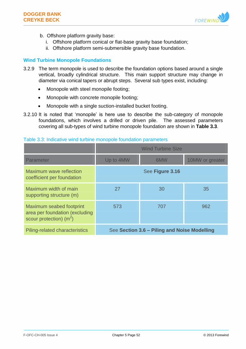
DOGGER BANK CREYKE BECK
F-OFC-CH-005 Issue 4 Chapter 5 Page 52 © 2013 Forewind
b. Offshore platform gravity base:
i. Offshore platform conical or flat-base gravity base foundation;
ii. Offshore platform semi-submersible gravity base foundation.
Wind Turbine Monopole Foundations
3.2.9 The term monopole is used to describe the foundation options based around a single
vertical, broadly cylindrical structure. This main support structure may change in
diameter via conical tapers or abrupt steps. Several sub types exist, including:
Monopole with steel monopile footing;
Monopole with concrete monopile footing;
Monopole with a single suction-installed bucket footing.
3.2.10 It is noted that ‘monopile’ is here use to describe the sub-category of monopole
foundations, which involves a drilled or driven pile. The assessed parameters
covering all sub-types of wind turbine monopole foundation are shown in Table 3.3.
Table 3.3: Indicative wind turbine monopole foundation parameters
Wind Turbine Size
Parameter Up to 4MW 6MW 10MW or greater
Maximum wave reflection
coefficient per foundation
See Figure 3.16
Maximum width of main
supporting structure (m)
27 30 35
Maximum seabed footprint
area per foundation (excluding
scour protection) (m2)
573 707 962
Piling-related characteristics See Section 3.6 – Piling and Noise Modelling
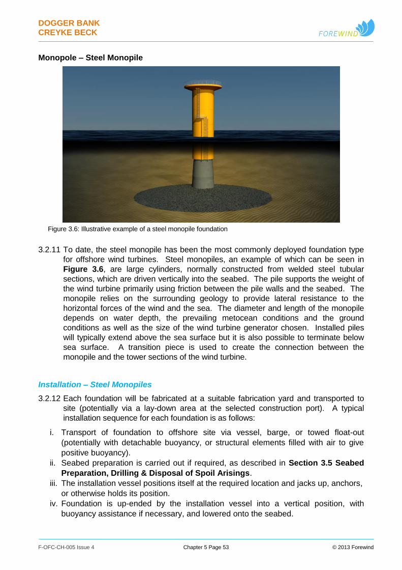
DOGGER BANK CREYKE BECK
F-OFC-CH-005 Issue 4 Chapter 5 Page 53 © 2013 Forewind
Monopole – Steel Monopile
Figure 3.6: Illustrative example of a steel monopile foundation
3.2.11 To date, the steel monopile has been the most commonly deployed foundation type
for offshore wind turbines. Steel monopiles, an example of which can be seen in
Figure 3.6, are large cylinders, normally constructed from welded steel tubular
sections, which are driven vertically into the seabed. The pile supports the weight of
the wind turbine primarily using friction between the pile walls and the seabed. The
monopile relies on the surrounding geology to provide lateral resistance to the
horizontal forces of the wind and the sea. The diameter and length of the monopile
depends on water depth, the prevailing metocean conditions and the ground
conditions as well as the size of the wind turbine generator chosen. Installed piles
will typically extend above the sea surface but it is also possible to terminate below
sea surface. A transition piece is used to create the connection between the
monopile and the tower sections of the wind turbine.
Installation – Steel Monopiles
3.2.12 Each foundation will be fabricated at a suitable fabrication yard and transported to
site (potentially via a lay-down area at the selected construction port). A typical
installation sequence for each foundation is as follows:
i. Transport of foundation to offshore site via vessel, barge, or towed float-out
(potentially with detachable buoyancy, or structural elements filled with air to give
positive buoyancy).
ii. Seabed preparation is carried out if required, as described in Section 3.5 Seabed
Preparation, Drilling & Disposal of Spoil Arisings.
iii. The installation vessel positions itself at the required location and jacks up, anchors,
or otherwise holds its position.
iv. Foundation is up-ended by the installation vessel into a vertical position, with
buoyancy assistance if necessary, and lowered onto the seabed.

DOGGER BANK CREYKE BECK
F-OFC-CH-005 Issue 4 Chapter 5 Page 54 © 2013 Forewind
v. Installation of monopiles progressed by piling (as described within Section 3.6
Piling & Noise Modelling), drilling (as described within Section 3.5 Seabed
Preparation, Drilling & Disposal of Spoil Arisings), or a combination as required
by site specific soil conditions and technical and economic viability.
vi. Installation of transition piece and any ancillary equipment, such as cable J-tubes
and boat landings, which are not integral to the main structure, including their
alignment and fastening (typically grouting, bolting or welding).
vii. Installation of scour protection if required, as described in Section 3.3 Protection
Against Foundation Scour & Subsea Damage (noting that this can alternatively
happen before foundation arrives on site).
Monopole – Concrete Monopile
Figure 3.7: Illustrative visualisation of the installation of concrete monopile
Courtesy of Ballast Nedam Offshore
3.2.13 An alternative monopile solution currently under development consists of a steel
reinforced concrete design. Concrete monopiles, an example of which can be seen
in Figure 3.7, would typically comprise a number of pre-cast reinforced concrete ring
sections which may be partially fitted and grouted together prior to floating out to site.
Additional rings are then joined onto the top as installation progresses, gradually
lengthening the pile as it penetrates into the seabed, until the top section with access
platforms and wind turbine tower connecting flange is attached last. Concrete
monopiles are commonly characterised by their large diameters, thick walls, and
piling-free installation methodologies.
Installation – Concrete Monopile
3.2.14 Each concrete monopile will be fabricated at a suitable fabrication yard and
transported to site (potentially via a lay-down area at the selected construction port).
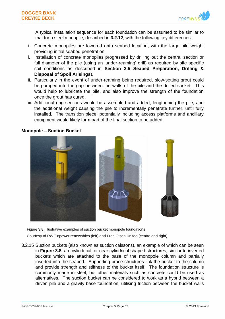
DOGGER BANK CREYKE BECK
F-OFC-CH-005 Issue 4 Chapter 5 Page 55 © 2013 Forewind
A typical installation sequence for each foundation can be assumed to be similar to
that for a steel monopile, described in 3.2.12, with the following key differences:
i. Concrete monopiles are lowered onto seabed location, with the large pile weight
providing initial seabed penetration.
i. Installation of concrete monopiles progressed by drilling out the central section or
full diameter of the pile (using an ‘under-reaming’ drill) as required by site specific
soil conditions as described in Section 3.5 Seabed Preparation, Drilling &
Disposal of Spoil Arisings).
ii. Particularly in the event of under-reaming being required, slow-setting grout could
be pumped into the gap between the walls of the pile and the drilled socket. This
would help to lubricate the pile, and also improve the strength of the foundation
once the grout has cured.
iii. Additional ring sections would be assembled and added, lengthening the pile, and
the additional weight causing the pile to incrementally penetrate further, until fully
installed. The transition piece, potentially including access platforms and ancillary
equipment would likely form part of the final section to be added.
Monopole – Suction Bucket
Figure 3.8: Illustrative examples of suction bucket monopole foundations
Courtesy of RWE npower renewables (left) and Fred Olsen United (centre and right)
3.2.15 Suction buckets (also known as suction caissons), an example of which can be seen
in Figure 3.8, are cylindrical, or near cylindrical-shaped structures, similar to inverted
buckets which are attached to the base of the monopole column and partially
inserted into the seabed. Supporting brace structures link the bucket to the column
and provide strength and stiffness to the bucket itself. The foundation structure is
commonly made in steel, but other materials such as concrete could be used as
alternatives. The suction bucket can be considered to work as a hybrid between a
driven pile and a gravity base foundation; utilising friction between the bucket walls

DOGGER BANK CREYKE BECK
F-OFC-CH-005 Issue 4 Chapter 5 Page 56 © 2013 Forewind
and soil, as well as the mass of the soil contained within the bucket - plus additional
suction effects which resist movement of the whole mass below the seabed.
Installation – Monopole Suction Bucket
3.2.16 Each suction bucket monopole will be fabricated at a suitable fabrication yard and
transported to site (potentially via a lay-down area at the selected construction port).
A typical installation sequence for each foundation can be assumed to be similar to
that for a steel monopile, described in 3.2.12, with the following key differences:
i. The bucket foundation is fitted with a pump and control unit (if detachable) during
installation.
ii. Suction bucket lowered to seabed location, with structure weight providing initial
seabed penetration.
iii. Negative pressure is then applied within the bucket structure by means of the
pumps and it is embedded until the top sits as close as possible to the seabed.
Water jets within the bucket structure may be used to assist in penetrating the
sediments and controlling the installation process.
iv. A layer of grout may be pumped into the top of the bucket after installation, to
provide a uniform bearing surface between the top of the suction bucket and the
seabed.
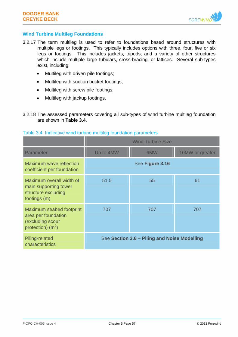
DOGGER BANK CREYKE BECK
F-OFC-CH-005 Issue 4 Chapter 5 Page 57 © 2013 Forewind
Wind Turbine Multileg Foundations
3.2.17 The term multileg is used to refer to foundations based around structures with
multiple legs or footings. This typically includes options with three, four, five or six
legs or footings. This includes jackets, tripods, and a variety of other structures
which include multiple large tubulars, cross-bracing, or lattices. Several sub-types
exist, including:
Multileg with driven pile footings;
Multileg with suction bucket footings;
Multileg with screw pile footings;
Multileg with jackup footings.
3.2.18 The assessed parameters covering all sub-types of wind turbine multileg foundation
are shown in Table 3.4.
Table 3.4: Indicative wind turbine multileg foundation parameters
Wind Turbine Size
Parameter Up to 4MW 6MW 10MW or greater
Maximum wave reflection
coefficient per foundation
See Figure 3.16
Maximum overall width of
main supporting tower
structure excluding
footings (m)
51.5 55 61
Maximum seabed footprint
area per foundation
(excluding scour
protection) (m2)
707 707 707
Piling-related
characteristics
See Section 3.6 – Piling and Noise Modelling
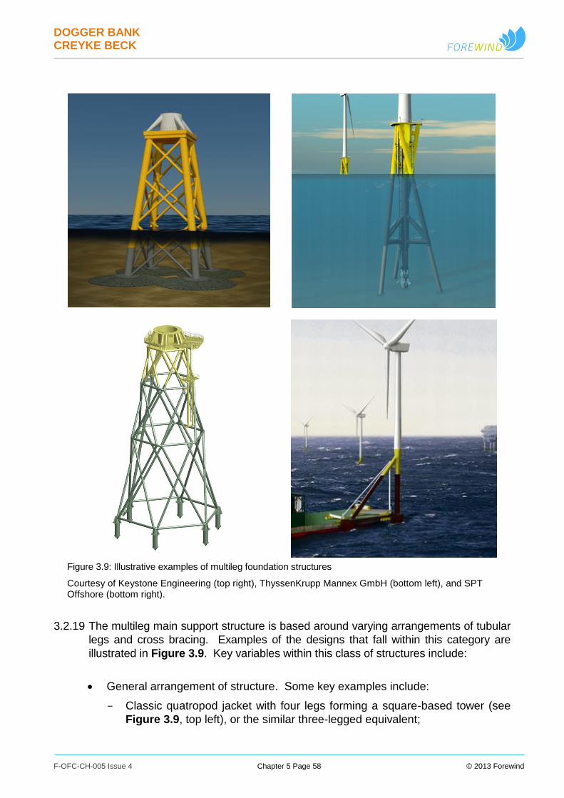
DOGGER BANK CREYKE BECK
F-OFC-CH-005 Issue 4 Chapter 5 Page 58 © 2013 Forewind
Figure 3.9: Illustrative examples of multileg foundation structures
Courtesy of Keystone Engineering (top right), ThyssenKrupp Mannex GmbH (bottom left), and SPT Offshore (bottom right).
3.2.19 The multileg main support structure is based around varying arrangements of tubular
legs and cross bracing. Examples of the designs that fall within this category are
illustrated in Figure 3.9. Key variables within this class of structures include:
General arrangement of structure. Some key examples include:
Classic quatropod jacket with four legs forming a square-based tower (see
Figure 3.9, top left), or the similar three-legged equivalent;
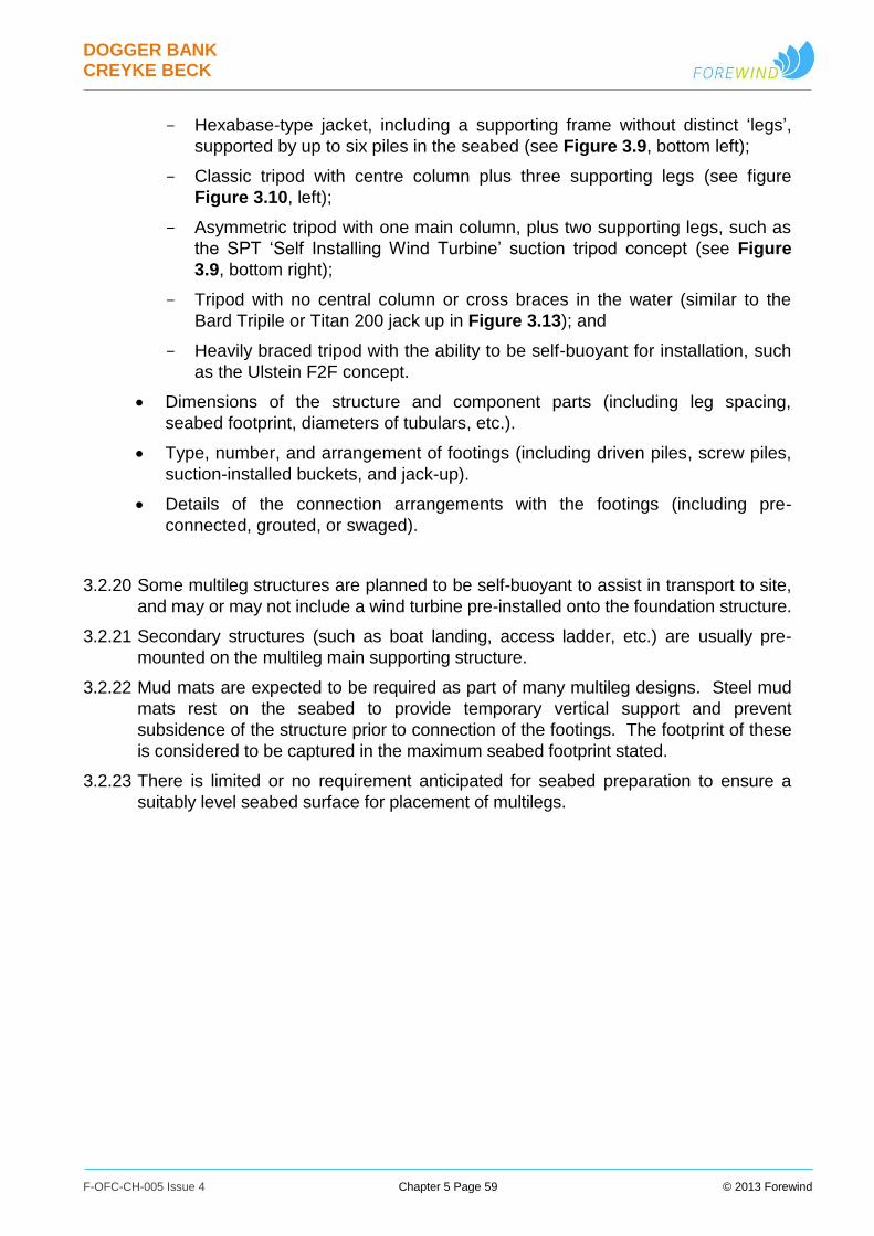
DOGGER BANK CREYKE BECK
F-OFC-CH-005 Issue 4 Chapter 5 Page 59 © 2013 Forewind
Hexabase-type jacket, including a supporting frame without distinct ‘legs’,
supported by up to six piles in the seabed (see Figure 3.9, bottom left);
Classic tripod with centre column plus three supporting legs (see figure
Figure 3.10, left);
Asymmetric tripod with one main column, plus two supporting legs, such as
the SPT ‘Self Installing Wind Turbine’ suction tripod concept (see Figure
3.9, bottom right);
Tripod with no central column or cross braces in the water (similar to the
Bard Tripile or Titan 200 jack up in Figure 3.13); and
Heavily braced tripod with the ability to be self-buoyant for installation, such
as the Ulstein F2F concept.
Dimensions of the structure and component parts (including leg spacing,
seabed footprint, diameters of tubulars, etc.).
Type, number, and arrangement of footings (including driven piles, screw piles,
suction-installed buckets, and jack-up).
Details of the connection arrangements with the footings (including pre-
connected, grouted, or swaged).
3.2.20 Some multileg structures are planned to be self-buoyant to assist in transport to site,
and may or may not include a wind turbine pre-installed onto the foundation structure.
3.2.21 Secondary structures (such as boat landing, access ladder, etc.) are usually pre-
mounted on the multileg main supporting structure.
3.2.22 Mud mats are expected to be required as part of many multileg designs. Steel mud
mats rest on the seabed to provide temporary vertical support and prevent
subsidence of the structure prior to connection of the footings. The footprint of these
is considered to be captured in the maximum seabed footprint stated.
3.2.23 There is limited or no requirement anticipated for seabed preparation to ensure a
suitably level seabed surface for placement of multilegs.
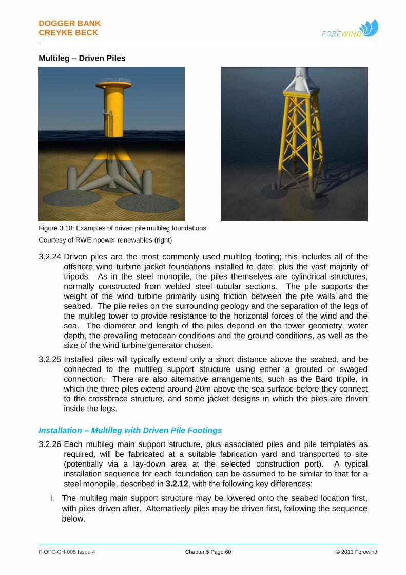
DOGGER BANK CREYKE BECK
F-OFC-CH-005 Issue 4 Chapter 5 Page 60 © 2013 Forewind
Multileg – Driven Piles
Figure 3.10: Examples of driven pile multileg foundations
Courtesy of RWE npower renewables (right)
3.2.24 Driven piles are the most commonly used multileg footing; this includes all of the
offshore wind turbine jacket foundations installed to date, plus the vast majority of
tripods. As in the steel monopile, the piles themselves are cylindrical structures,
normally constructed from welded steel tubular sections. The pile supports the
weight of the wind turbine primarily using friction between the pile walls and the
seabed. The pile relies on the surrounding geology and the separation of the legs of
the multileg tower to provide resistance to the horizontal forces of the wind and the
sea. The diameter and length of the piles depend on the tower geometry, water
depth, the prevailing metocean conditions and the ground conditions, as well as the
size of the wind turbine generator chosen.
3.2.25 Installed piles will typically extend only a short distance above the seabed, and be
connected to the multileg support structure using either a grouted or swaged
connection. There are also alternative arrangements, such as the Bard tripile, in
which the three piles extend around 20m above the sea surface before they connect
to the crossbrace structure, and some jacket designs in which the piles are driven
inside the legs.
Installation – Multileg with Driven Pile Footings
3.2.26 Each multileg main support structure, plus associated piles and pile templates as
required, will be fabricated at a suitable fabrication yard and transported to site
(potentially via a lay-down area at the selected construction port). A typical
installation sequence for each foundation can be assumed to be similar to that for a
steel monopile, described in 3.2.12, with the following key differences:
i. The multileg main support structure may be lowered onto the seabed location first,
with piles driven after. Alternatively piles may be driven first, following the sequence
below.
DOGGER BANK CREYKE BECK
F-OFC-CH-005 Issue 4 Chapter 5 Page 61 © 2013 Forewind
ii. Installation of piles progressed by driving, drilling (both driving and drilling are
described within Section 3.5 Seabed Preparation, Drilling & Disposal of Spoil
Arisings), or a combination as required by site specific soil conditions and technical
and economic viability.
iii. If further piles are required at this foundation location, the vessel or equipment may
be re-positioned to allow additional piles to be installed using a similar sequence.
iv. When all required piles are in place, installation of main support structure may
occur, if not already in position. The main structure is then secured to the piles
(typically grouted or swaged into place within pile sleeves).
Multileg – Suction Buckets
Figure 3.11: Examples of existing suction bucket multileg foundations (left) and concept designs (right)
Courtesy of Statoil (left), and Ulstein Group (right)
3.2.27 Suction buckets have been used as foundations for jacket structures in the oil and
gas industry and are considered a viable future technology for offshore wind jacket
foundations. Suction tripod concepts are also under development (such as the ‘Self
Installing Wind Turbine’ concept shown in Figure 3.9 developed by the company
SPT, and the self-buoyant F2F concept by the company Ulstein, shown in Figure
3.11). Suction foundations have been identified as being potentially well suited to the
Dogger Bank site. An example of a previous suction bucket design can be seen in
Figure 3.11.
3.2.28 As with mono-bucket structures described above, multileg suction buckets are
cylindrical, or near cylindrical-shaped structures, similar to inverted buckets, which
are inserted into the seabed and attached to the base of the foundation main
structure. Supporting brace structures link the bucket to the structure and provide
strength and stiffness to the bucket itself. The suction buckets may be made of steel
and/or reinforced concrete. Ballast may be required within the main structure to
ensure resistance of uplift forces during operation, and potentially to ease installation.
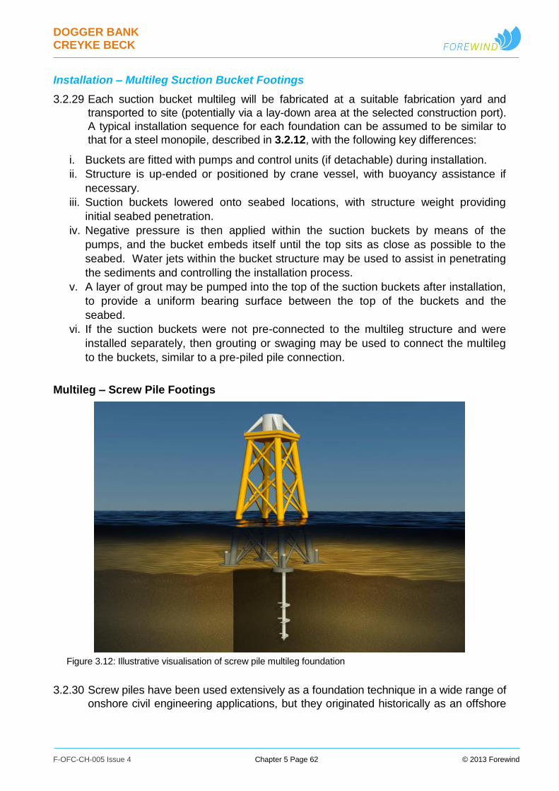
DOGGER BANK CREYKE BECK
F-OFC-CH-005 Issue 4 Chapter 5 Page 62 © 2013 Forewind
Installation – Multileg Suction Bucket Footings
3.2.29 Each suction bucket multileg will be fabricated at a suitable fabrication yard and
transported to site (potentially via a lay-down area at the selected construction port).
A typical installation sequence for each foundation can be assumed to be similar to
that for a steel monopile, described in 3.2.12, with the following key differences:
i. Buckets are fitted with pumps and control units (if detachable) during installation.
ii. Structure is up-ended or positioned by crane vessel, with buoyancy assistance if
necessary.
iii. Suction buckets lowered onto seabed locations, with structure weight providing
initial seabed penetration.
iv. Negative pressure is then applied within the suction buckets by means of the
pumps, and the bucket embeds itself until the top sits as close as possible to the
seabed. Water jets within the bucket structure may be used to assist in penetrating
the sediments and controlling the installation process.
v. A layer of grout may be pumped into the top of the suction buckets after installation,
to provide a uniform bearing surface between the top of the buckets and the
seabed.
vi. If the suction buckets were not pre-connected to the multileg structure and were
installed separately, then grouting or swaging may be used to connect the multileg
to the buckets, similar to a pre-piled pile connection.
Multileg – Screw Pile Footings
Figure 3.12: Illustrative visualisation of screw pile multileg foundation
3.2.30 Screw piles have been used extensively as a foundation technique in a wide range of
onshore civil engineering applications, but they originated historically as an offshore
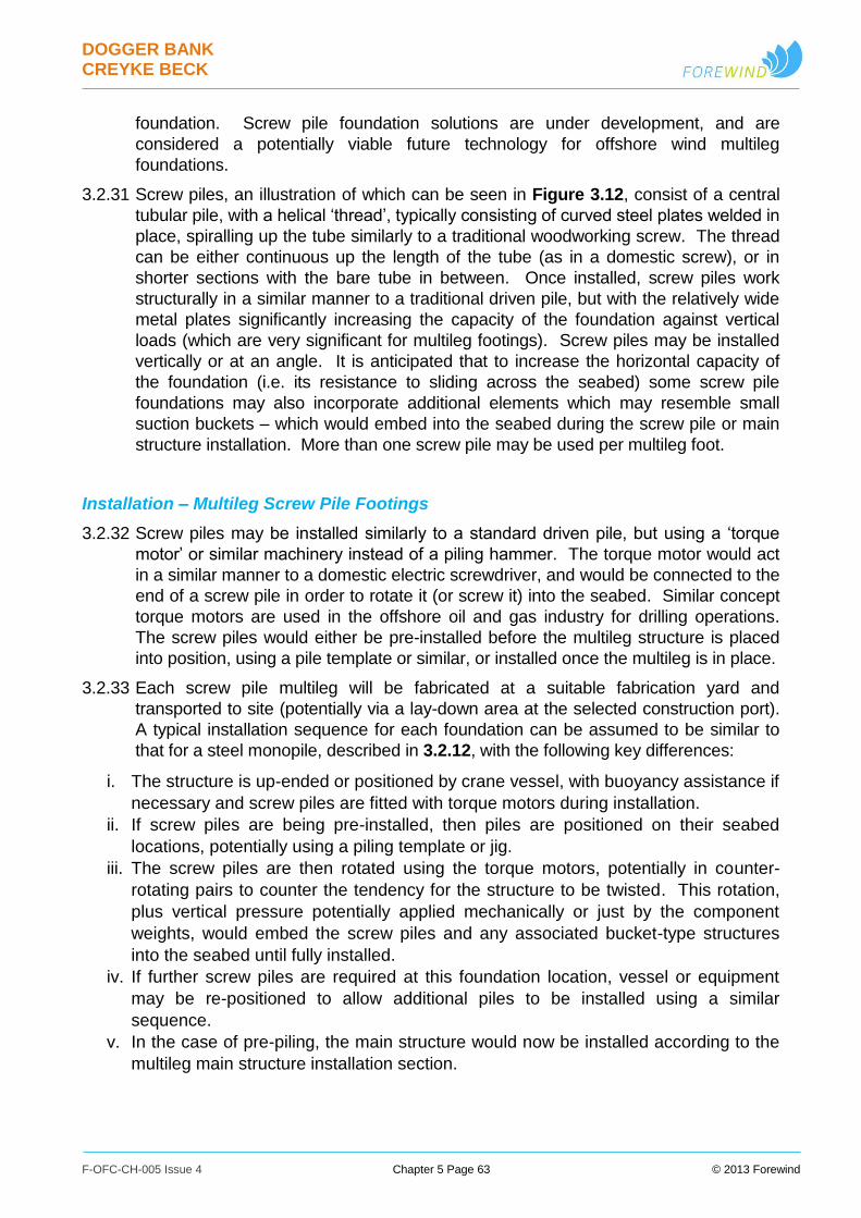
DOGGER BANK CREYKE BECK
F-OFC-CH-005 Issue 4 Chapter 5 Page 63 © 2013 Forewind
foundation. Screw pile foundation solutions are under development, and are
considered a potentially viable future technology for offshore wind multileg
foundations.
3.2.31 Screw piles, an illustration of which can be seen in Figure 3.12, consist of a central
tubular pile, with a helical ‘thread’, typically consisting of curved steel plates welded in
place, spiralling up the tube similarly to a traditional woodworking screw. The thread
can be either continuous up the length of the tube (as in a domestic screw), or in
shorter sections with the bare tube in between. Once installed, screw piles work
structurally in a similar manner to a traditional driven pile, but with the relatively wide
metal plates significantly increasing the capacity of the foundation against vertical
loads (which are very significant for multileg footings). Screw piles may be installed
vertically or at an angle. It is anticipated that to increase the horizontal capacity of
the foundation (i.e. its resistance to sliding across the seabed) some screw pile
foundations may also incorporate additional elements which may resemble small
suction buckets – which would embed into the seabed during the screw pile or main
structure installation. More than one screw pile may be used per multileg foot.
Installation – Multileg Screw Pile Footings
3.2.32 Screw piles may be installed similarly to a standard driven pile, but using a ‘torque
motor’ or similar machinery instead of a piling hammer. The torque motor would act
in a similar manner to a domestic electric screwdriver, and would be connected to the
end of a screw pile in order to rotate it (or screw it) into the seabed. Similar concept
torque motors are used in the offshore oil and gas industry for drilling operations.
The screw piles would either be pre-installed before the multileg structure is placed
into position, using a pile template or similar, or installed once the multileg is in place.
3.2.33 Each screw pile multileg will be fabricated at a suitable fabrication yard and
transported to site (potentially via a lay-down area at the selected construction port).
A typical installation sequence for each foundation can be assumed to be similar to
that for a steel monopile, described in 3.2.12, with the following key differences:
i. The structure is up-ended or positioned by crane vessel, with buoyancy assistance if
necessary and screw piles are fitted with torque motors during installation.
ii. If screw piles are being pre-installed, then piles are positioned on their seabed
locations, potentially using a piling template or jig.
iii. The screw piles are then rotated using the torque motors, potentially in counter-
rotating pairs to counter the tendency for the structure to be twisted. This rotation,
plus vertical pressure potentially applied mechanically or just by the component
weights, would embed the screw piles and any associated bucket-type structures
into the seabed until fully installed.
iv. If further screw piles are required at this foundation location, vessel or equipment
may be re-positioned to allow additional piles to be installed using a similar
sequence.
v. In the case of pre-piling, the main structure would now be installed according to the
multileg main structure installation section.
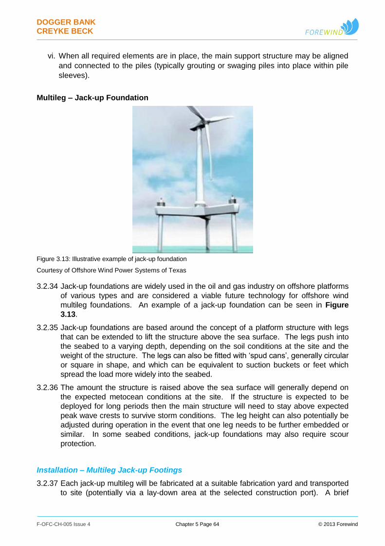
DOGGER BANK CREYKE BECK
F-OFC-CH-005 Issue 4 Chapter 5 Page 64 © 2013 Forewind
vi. When all required elements are in place, the main support structure may be aligned
and connected to the piles (typically grouting or swaging piles into place within pile
sleeves).
Multileg – Jack-up Foundation
Figure 3.13: Illustrative example of jack-up foundation
Courtesy of Offshore Wind Power Systems of Texas
3.2.34 Jack-up foundations are widely used in the oil and gas industry on offshore platforms
of various types and are considered a viable future technology for offshore wind
multileg foundations. An example of a jack-up foundation can be seen in Figure
3.13.
3.2.35 Jack-up foundations are based around the concept of a platform structure with legs
that can be extended to lift the structure above the sea surface. The legs push into
the seabed to a varying depth, depending on the soil conditions at the site and the
weight of the structure. The legs can also be fitted with ‘spud cans’, generally circular
or square in shape, and which can be equivalent to suction buckets or feet which
spread the load more widely into the seabed.
3.2.36 The amount the structure is raised above the sea surface will generally depend on
the expected metocean conditions at the site. If the structure is expected to be
deployed for long periods then the main structure will need to stay above expected
peak wave crests to survive storm conditions. The leg height can also potentially be
adjusted during operation in the event that one leg needs to be further embedded or
similar. In some seabed conditions, jack-up foundations may also require scour
protection.
Installation – Multileg Jack-up Footings
3.2.37 Each jack-up multileg will be fabricated at a suitable fabrication yard and transported
to site (potentially via a lay-down area at the selected construction port). A brief

DOGGER BANK CREYKE BECK
F-OFC-CH-005 Issue 4 Chapter 5 Page 65 © 2013 Forewind
typical installation sequence for each foundation can be assumed to be similar to that
for a steel monopile, described in 3.2.12, with the following key differences:
i. Jack-up positioned and legs are extended to the seabed.
ii. Jack-up mechanisms embed legs or spud cans, and structure is lifted to the desired
installed height.
iii. If required, suction pumps or water jets may be used in a manner similar to a
suction bucket installation, to assist or control the installation of suction bucket-type
footings.
DOGGER BANK CREYKE BECK
F-OFC-CH-005 Issue 4 Chapter 5 Page 66 © 2013 Forewind
Wind Turbine Gravity Base Foundations
3.2.38 A gravity base structure is a large diameter steel, concrete, or steel and concrete
combination base which sits on the seabed. Two sub types have been identified:
Conical gravity base;
Flat-based gravity base.
3.2.39 The assessed parameters covering all sub-types of wind turbine gravity base
foundation are shown in Table 3.5.
Table 3.5: Indicative wind turbine gravity base foundation parameters
Wind Turbine Size
Parameter Up to 4MW 6MW 10MW or greater
Maximum wave reflection
coefficient per foundation
See Figure 3.16
Maximum overall width of
foundation structure (m)
47 50 55
Maximum seabed footprint area
per foundation (excluding scour
protection) (m2)
1,735 1,963 2,376
3.2.40 The gravity base solution primarily relies on its size and weight to maintain the
stability of the structure. Gravity base foundations can additionally incorporate steel
or concrete ‘skirts’ around the perimeter which could penetrate into the seabed to
help resist horizontal movement, reduce the impact of scour, and offer similar
foundation benefits to those offered by a suction bucket. The base of the structure
Figure 3.14: Illustrative examples of conical gravity base foundations
Courtesy of Seatower (left), Skanska (centre) and GBF (right)
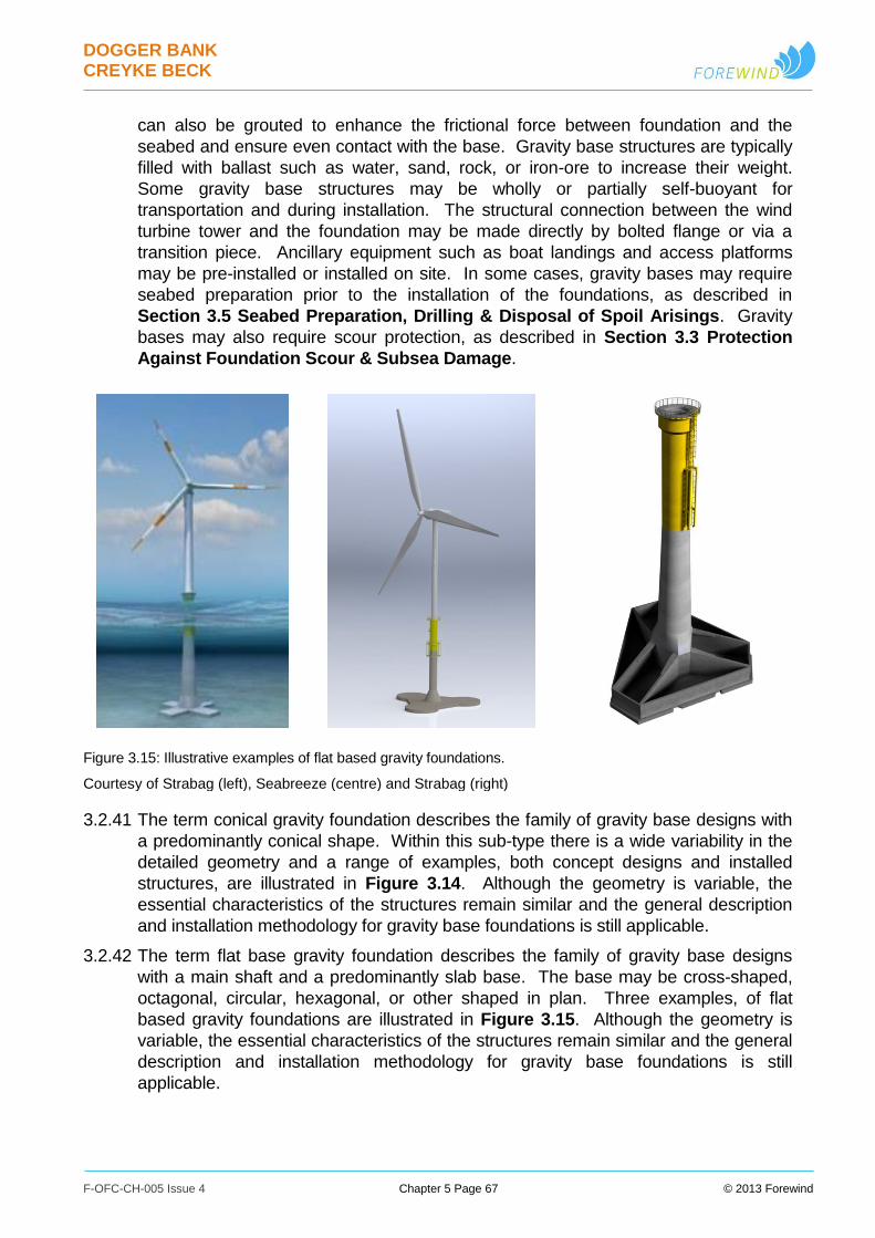
DOGGER BANK CREYKE BECK
F-OFC-CH-005 Issue 4 Chapter 5 Page 67 © 2013 Forewind
can also be grouted to enhance the frictional force between foundation and the
seabed and ensure even contact with the base. Gravity base structures are typically
filled with ballast such as water, sand, rock, or iron-ore to increase their weight.
Some gravity base structures may be wholly or partially self-buoyant for
transportation and during installation. The structural connection between the wind
turbine tower and the foundation may be made directly by bolted flange or via a
transition piece. Ancillary equipment such as boat landings and access platforms
may be pre-installed or installed on site. In some cases, gravity bases may require
seabed preparation prior to the installation of the foundations, as described in
Section 3.5 Seabed Preparation, Drilling & Disposal of Spoil Arisings. Gravity
bases may also require scour protection, as described in Section 3.3 Protection
Against Foundation Scour & Subsea Damage.
Figure 3.15: Illustrative examples of flat based gravity foundations.
Courtesy of Strabag (left), Seabreeze (centre) and Strabag (right)
3.2.41 The term conical gravity foundation describes the family of gravity base designs with
a predominantly conical shape. Within this sub-type there is a wide variability in the
detailed geometry and a range of examples, both concept designs and installed
structures, are illustrated in Figure 3.14. Although the geometry is variable, the
essential characteristics of the structures remain similar and the general description
and installation methodology for gravity base foundations is still applicable.
3.2.42 The term flat base gravity foundation describes the family of gravity base designs
with a main shaft and a predominantly slab base. The base may be cross-shaped,
octagonal, circular, hexagonal, or other shaped in plan. Three examples, of flat
based gravity foundations are illustrated in Figure 3.15. Although the geometry is
variable, the essential characteristics of the structures remain similar and the general
description and installation methodology for gravity base foundations is still
applicable.
DOGGER BANK CREYKE BECK
F-OFC-CH-005 Issue 4 Chapter 5 Page 68 © 2013 Forewind
Installation – Gravity Base Foundation
3.2.43 Each gravity base will be fabricated at a suitable fabrication yard and transported to
site (potentially via a lay-down area at the selected construction port). A typical
installation sequence for each foundation can be assumed to be similar to that for a
steel monopile, described in 3.2.12, with the following key differences:
i. The gravity base is positioned and the foundation is then filled with ballast as
required to be lowered to the seabed by controlled buoyancy adjustment.
ii. If required, suction pumps or water jets may be used in a manner similar to a
suction bucket installation, to assist in skirt penetration or control the installation of
skirted gravity base foundations.
iii. Under-base grouting, if required to improve contact between the gravity base and
seabed, could be supplied by flexible hose, potentially including pre-installed piping
to allow access under the base.
Wind Turbine Foundation Wave Reflection Coefficients
3.2.44 The obstruction the wind turbine foundations provide to the passage of waves and
tidal currents is the key input to assessment of impacts upon marine physical
processes. Following consultation with Royal HaskoningDHV and the Danish
Hydraulic Institute, who are experts in the field of fluid flow modelling around marine
foundation structures, the “wave reflection coefficient” was identified as the value
which best describes both these properties of a foundation structure. The basis for
this is discussed within Appendix 5.B Dogger Bank Creyke Beck Foundation
Characterisation Study (Royal Haskoning, 2012).
3.2.45 An appropriate methodology has therefore been developed by Royal HaskoningDHV
and the Danish Hydraulic Institute, to calculate a foundation’s wave reflection
coefficient, and this is described in detail within Appendix 5.B Dogger Bank Creyke
Beck Foundation Characterisation Study (Royal Haskoning, 2012).
3.2.46 Based on this design and methodology, a set of realistic worst case wave reflection
coefficient values have been produced for the range of wind turbine foundation sizes
and water depths (referenced to mean sea level). These realistic worst case values
are presented in Figure 3.16.
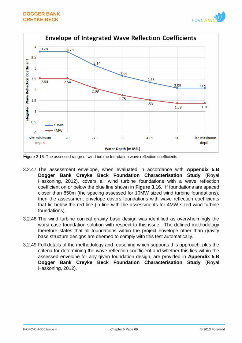
DOGGER BANK CREYKE BECK
F-OFC-CH-005 Issue 4 Chapter 5 Page 69 © 2013 Forewind
Figure 3.16: The assessed range of wind turbine foundation wave reflection coefficients
3.2.47 The assessment envelope, when evaluated in accordance with Appendix 5.B
Dogger Bank Creyke Beck Foundation Characterisation Study (Royal
Haskoning, 2012), covers all wind turbine foundations with a wave reflection
coefficient on or below the blue line shown in Figure 3.16. If foundations are spaced
closer than 850m (the spacing assessed for 10MW sized wind turbine foundations),
then the assessment envelope covers foundations with wave reflection coefficients
that lie below the red line (in line with the assessments for 4MW sized wind turbine
foundations).
3.2.48 The wind turbine conical gravity base design was identified as overwhelmingly the
worst-case foundation solution with respect to this issue. The defined methodology
therefore states that all foundations within the project envelope other than gravity
base structure designs are deemed to comply with this test automatically.
3.2.49 Full details of the methodology and reasoning which supports this approach, plus the
criteria for determining the wave reflection coefficient and whether this lies within the
assessed envelope for any given foundation design, are provided in Appendix 5.B
Dogger Bank Creyke Beck Foundation Characterisation Study (Royal
Haskoning, 2012).
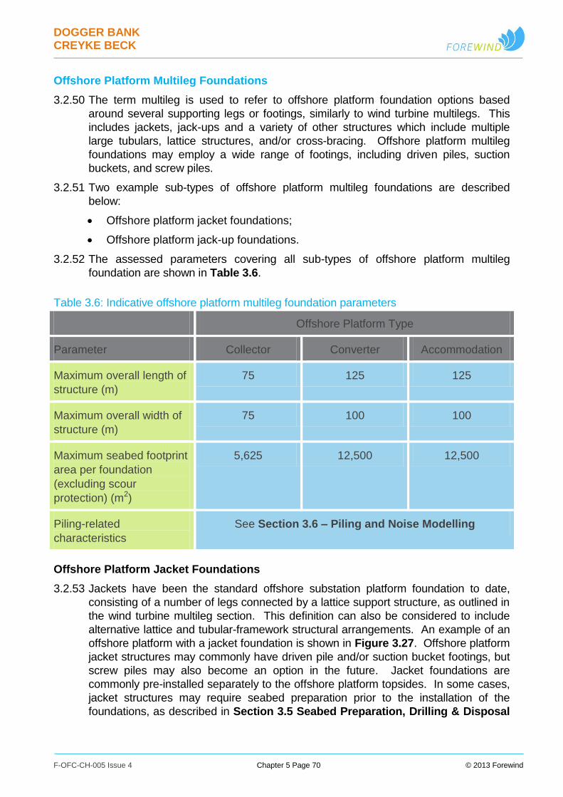
DOGGER BANK CREYKE BECK
F-OFC-CH-005 Issue 4 Chapter 5 Page 70 © 2013 Forewind
Offshore Platform Multileg Foundations
3.2.50 The term multileg is used to refer to offshore platform foundation options based
around several supporting legs or footings, similarly to wind turbine multilegs. This
includes jackets, jack-ups and a variety of other structures which include multiple
large tubulars, lattice structures, and/or cross-bracing. Offshore platform multileg
foundations may employ a wide range of footings, including driven piles, suction
buckets, and screw piles.
3.2.51 Two example sub-types of offshore platform multileg foundations are described
below:
Offshore platform jacket foundations;
Offshore platform jack-up foundations.
3.2.52 The assessed parameters covering all sub-types of offshore platform multileg
foundation are shown in Table 3.6.
Table 3.6: Indicative offshore platform multileg foundation parameters
Offshore Platform Type
Parameter Collector Converter Accommodation
Maximum overall length of
structure (m)
75 125 125
Maximum overall width of
structure (m)
75 100 100
Maximum seabed footprint
area per foundation
(excluding scour
protection) (m2)
5,625 12,500 12,500
Piling-related
characteristics
See Section 3.6 – Piling and Noise Modelling
Offshore Platform Jacket Foundations
3.2.53 Jackets have been the standard offshore substation platform foundation to date,
consisting of a number of legs connected by a lattice support structure, as outlined in
the wind turbine multileg section. This definition can also be considered to include
alternative lattice and tubular-framework structural arrangements. An example of an
offshore platform with a jacket foundation is shown in Figure 3.27. Offshore platform
jacket structures may commonly have driven pile and/or suction bucket footings, but
screw piles may also become an option in the future. Jacket foundations are
commonly pre-installed separately to the offshore platform topsides. In some cases,
jacket structures may require seabed preparation prior to the installation of the
foundations, as described in Section 3.5 Seabed Preparation, Drilling & Disposal
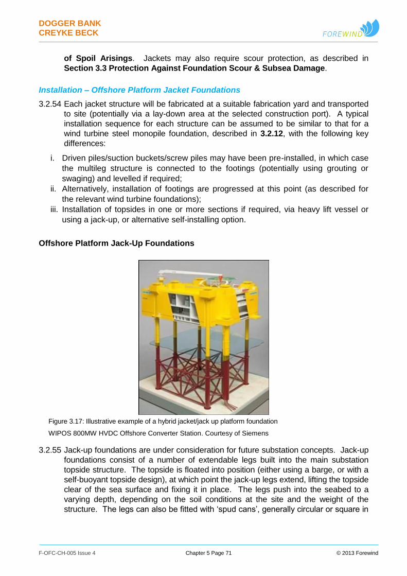
DOGGER BANK CREYKE BECK
F-OFC-CH-005 Issue 4 Chapter 5 Page 71 © 2013 Forewind
of Spoil Arisings. Jackets may also require scour protection, as described in
Section 3.3 Protection Against Foundation Scour & Subsea Damage.
Installation – Offshore Platform Jacket Foundations
3.2.54 Each jacket structure will be fabricated at a suitable fabrication yard and transported
to site (potentially via a lay-down area at the selected construction port). A typical
installation sequence for each structure can be assumed to be similar to that for a
wind turbine steel monopile foundation, described in 3.2.12, with the following key
differences:
i. Driven piles/suction buckets/screw piles may have been pre-installed, in which case
the multileg structure is connected to the footings (potentially using grouting or
swaging) and levelled if required;
ii. Alternatively, installation of footings are progressed at this point (as described for
the relevant wind turbine foundations);
iii. Installation of topsides in one or more sections if required, via heavy lift vessel or
using a jack-up, or alternative self-installing option.
Offshore Platform Jack-Up Foundations
Figure 3.17: Illustrative example of a hybrid jacket/jack up platform foundation
WIPOS 800MW HVDC Offshore Converter Station. Courtesy of Siemens
3.2.55 Jack-up foundations are under consideration for future substation concepts. Jack-up
foundations consist of a number of extendable legs built into the main substation
topside structure. The topside is floated into position (either using a barge, or with a
self-buoyant topside design), at which point the jack-up legs extend, lifting the topside
clear of the sea surface and fixing it in place. The legs push into the seabed to a
varying depth, depending on the soil conditions at the site and the weight of the
structure. The legs can also be fitted with ‘spud cans’, generally circular or square in
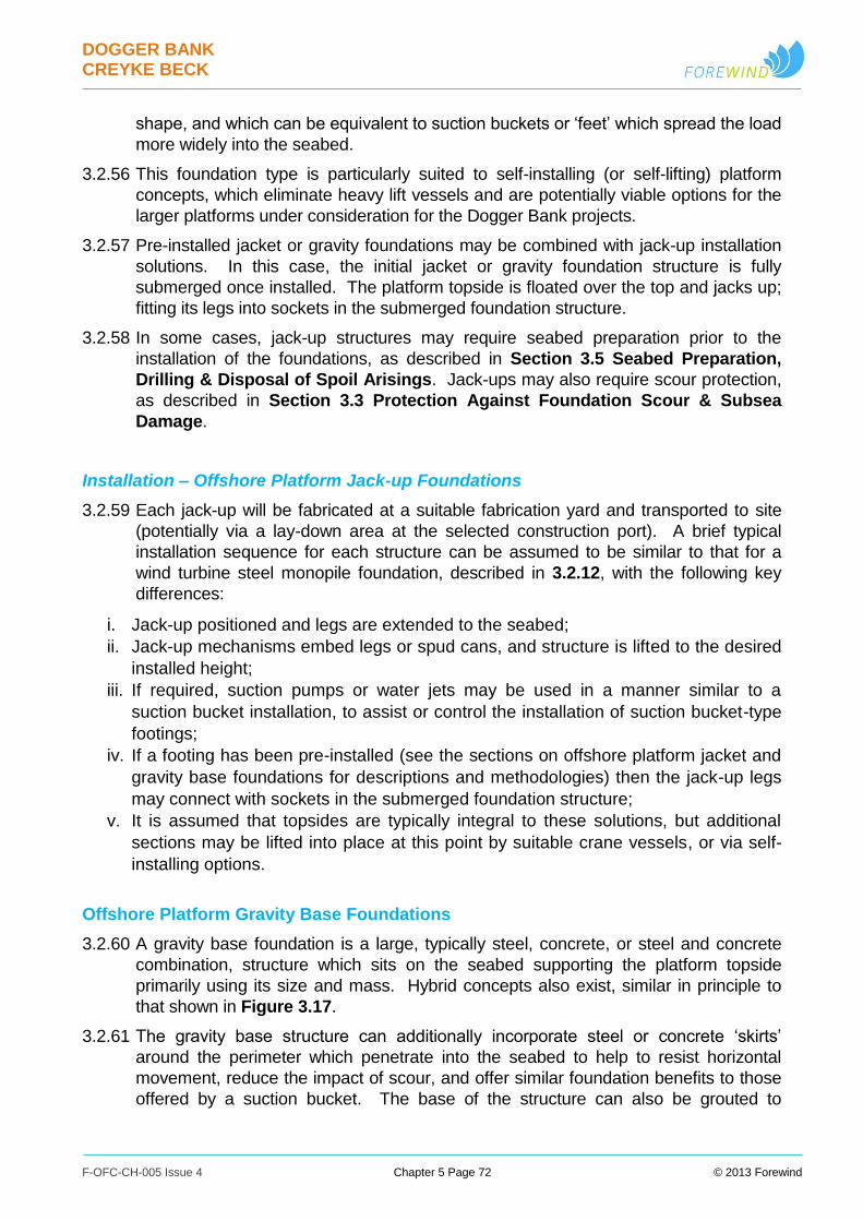
DOGGER BANK CREYKE BECK
F-OFC-CH-005 Issue 4 Chapter 5 Page 72 © 2013 Forewind
shape, and which can be equivalent to suction buckets or ‘feet’ which spread the load
more widely into the seabed.
3.2.56 This foundation type is particularly suited to self-installing (or self-lifting) platform
concepts, which eliminate heavy lift vessels and are potentially viable options for the
larger platforms under consideration for the Dogger Bank projects.
3.2.57 Pre-installed jacket or gravity foundations may be combined with jack-up installation
solutions. In this case, the initial jacket or gravity foundation structure is fully
submerged once installed. The platform topside is floated over the top and jacks up;
fitting its legs into sockets in the submerged foundation structure.
3.2.58 In some cases, jack-up structures may require seabed preparation prior to the
installation of the foundations, as described in Section 3.5 Seabed Preparation,
Drilling & Disposal of Spoil Arisings. Jack-ups may also require scour protection,
as described in Section 3.3 Protection Against Foundation Scour & Subsea
Damage.
Installation – Offshore Platform Jack-up Foundations
3.2.59 Each jack-up will be fabricated at a suitable fabrication yard and transported to site
(potentially via a lay-down area at the selected construction port). A brief typical
installation sequence for each structure can be assumed to be similar to that for a
wind turbine steel monopile foundation, described in 3.2.12, with the following key
differences:
i. Jack-up positioned and legs are extended to the seabed;
ii. Jack-up mechanisms embed legs or spud cans, and structure is lifted to the desired
installed height;
iii. If required, suction pumps or water jets may be used in a manner similar to a
suction bucket installation, to assist or control the installation of suction bucket-type
footings;
iv. If a footing has been pre-installed (see the sections on offshore platform jacket and
gravity base foundations for descriptions and methodologies) then the jack-up legs
may connect with sockets in the submerged foundation structure;
v. It is assumed that topsides are typically integral to these solutions, but additional
sections may be lifted into place at this point by suitable crane vessels, or via self-
installing options.
Offshore Platform Gravity Base Foundations
3.2.60 A gravity base foundation is a large, typically steel, concrete, or steel and concrete
combination, structure which sits on the seabed supporting the platform topside
primarily using its size and mass. Hybrid concepts also exist, similar in principle to
that shown in Figure 3.17.
3.2.61 The gravity base structure can additionally incorporate steel or concrete ‘skirts’
around the perimeter which penetrate into the seabed to help to resist horizontal
movement, reduce the impact of scour, and offer similar foundation benefits to those
offered by a suction bucket. The base of the structure can also be grouted to
DOGGER BANK CREYKE BECK
F-OFC-CH-005 Issue 4 Chapter 5 Page 73 © 2013 Forewind
enhance the frictional force between the foundation and the seabed and ensure even
contact with the base. Gravity base structures are typically hollow and filled with
ballast such as water, sand, rock, or iron-ore to increase their weight. If constructed
from concrete, the structure would typically be heavier, reducing the mass of
additional ballast required. In some cases, gravity bases may require seabed
preparation prior to the installation of the foundations, as described in Section 3.5
Seabed Preparation, Drilling & Disposal of Spoil Arisings. Gravity bases may
also require scour protection, as described in Section 3.3 Protection Against
Foundation Scour & Subsea Damage.
3.2.62 Two key gravity base foundation sub-types have been identified:
Offshore Platform Conical or Flat-Base Gravity Base Foundations.
Offshore Platform Semi-Submersible Gravity Base Foundations.
3.2.63 The assessed parameters covering all sub-types of offshore platform gravity base
foundation are shown in Table 3.7.
Table 3.7: Indicative offshore platform gravity base foundation parameters
Offshore Platform Type
Parameter Collector Converter Accommodation
Maximum overall length of
structure (m)
75 125 125
Maximum overall width of structure (m)
75 100 100
Maximum seabed footprint
area per foundation (excluding
scour protection) (m2)
5,625 12,500 12,500
Installation – Offshore Platform Gravity Base Foundations
3.2.64 Each gravity base will be fabricated at a suitable fabrication yard and transported to
site (potentially via a lay-down area at the selected construction port). A typical
installation sequence for each structure can be assumed to be similar to that for a
wind turbine steel monopile foundation, described in 3.2.12, with the following key
differences:
i. Gravity base is positioned and the foundation is then filled with ballast to be lowered
to the seabed by controlled buoyancy adjustment;
ii. If required, suction pumps or water jets may be used in a manner similar to a
suction bucket installation, to assist in skirt penetration or control the installation of
skirted gravity base foundations;
iii. Under-base grouting, if required to improve contact between the gravity base and
seabed, could be supplied by flexible hose, potentially including pre-installed piping
to allow access under the base;
DOGGER BANK CREYKE BECK
F-OFC-CH-005 Issue 4 Chapter 5 Page 74 © 2013 Forewind
iv. Installation of topsides if required, via heavy lift vessel or using a jack-up, or
alternative self-installing option.
Offshore Platform Conical or Flat-Base Gravity Base Foundations
3.2.65 This category describes a range of gravity bases with varying geometry; from flat
base solutions, with a main shaft and a predominantly slab base, to conical solutions,
characterised by a predominantly conical base tapering to a central shaft. For both
these foundation types the platform topsides are typically installed via bolted
connections or similar.
3.2.66 Although the geometry is variable, the essential characteristics of the structures
remain similar and the general description and installation methodology for gravity
base foundations is still applicable.
Offshore Platform Semi-Submersible Gravity Base Foundations
Figure 3.18: Illustrative example of a semi-submersible gravity base foundation
Courtesy of ABB
3.2.67 Semi-submersible gravity base solutions are a floating, self-installing platform
concept, where the buoyancy is predominantly provided by submerged portions of
the foundation structure. The typical structural arrangement comprises two large
submerged pontoons, with or without skirts, linked to the topside by a number of
large-diameter legs, as shown in Figure 3.18.
3.2.68 Although the structural arrangements are unlike conical or flat-base gravity
structures, the general description and installation methodology for gravity base
foundations is still applicable. Similarly to other gravity base concepts, the platform is
towed to site and ballasted down onto the seabed. When in place, this concept then
acts as a standard gravity base foundation, with the pontoons resting directly on the
seafloor.

DOGGER BANK CREYKE BECK
F-OFC-CH-005 Issue 4 Chapter 5 Page 75 © 2013 Forewind
Other Foundation Options
3.2.69 There are many foundation solutions being developed and proposed for wind
turbines and offshore platforms as the offshore wind industry grows and extends
further from shore and into deeper waters. It is anticipated that any other foundation
design that is developed, and that fits within the foundation design envelope, would
be considered by Forewind for these projects. Technological advances in installation
methods for foundations are also anticipated and those that fit within the
development envelope would also be considered for these projects.
Additional Foundation Components
3.2.70 Foundation structures include a range of additional components, some or all of which
may be required on a specific foundation design. A selection of key components is
described below.
Transition Piece
Figure 3.19: Typical wind turbine transition pieces
Transition pieces ready for installation (left) and transition piece being installed (right). By CHPV, courtesy of Scira Offshore Energy
3.2.71 The transition piece, as shown in Figure 3.19, is used as part of some wind turbine
foundations to form the interface between the wind turbine tower and the foundation.
It also serves other purposes, including housing electrical and communication
equipment, and mounting various ancillary components such as boat access
facilities, main access platforms, and J-tubes if required.
3.2.72 Transition pieces may be integrated at fabrication stage with the foundation, but are
typically craned into position and connected to the foundation structure after
installation via grouted or bolted (flange) connections and include means to ensure
DOGGER BANK CREYKE BECK
F-OFC-CH-005 Issue 4 Chapter 5 Page 76 © 2013 Forewind
the verticality of the wind turbine tower. Connection to the wind turbine tower is
typically by bolted (flange) connections.
J-tubes
3.2.73 J-tubes are metal tubes that route and protect cables as they travel up the foundation
to the base of the wind turbine tower or offshore platform topside. The metal tubes
are generally curved at the bottom of the foundation structure as it supports the cable
from travelling horizontally along the seabed to vertically up the foundation. J-tubes
may be housed internally or externally to the structure. The use of J-tubes is optional
and designs exist for which they are not required.
Corrosion Protection Systems
3.2.74 Structures will be protected appropriately against corrosion. Methods for the control
of corrosion include a corrosion allowance in the built structure, cathodic protection,
protective coating systems, and the use of corrosion resistant materials. The
methods used will be dependent on what is appropriate in each situation and
location.
3.2.75 It is anticipated that steel structures will primarily be protected by a combination of
cathodic protection and coating systems that are appropriate for seawater exposure.
3.2.76 Steelwork which is permanently submerged is commonly protected by a cathodic
protection system of a sacrificial anode type.
3.2.77 In addition, protective coating systems (such as paint systems, or galvanisation) are
commonly applied for protection in the splash zone and above. Areas of steelwork in
the submerged and splash zones may also be coated in order to reduce the load on
the cathodic protection system.
3.2.78 The selection of the appropriate corrosion protection method shall be made during
the detail design of the structures.
Boat Access System
3.2.79 The design of boat landing facilities, access ladders, and personnel access and rest
platforms is driven by the type and largest size of boat or personnel transfer system
anticipated to be used in the maintenance programme. Access systems may also be
used by third parties in emergency situations. Wind turbines commonly have either
one or two boat landings giving access to the structure. Foundations may include
advanced devices to improve access, such as lifts, movement compensating
platforms, or lock-on points, and offshore platforms may have more elaborate
systems, potentially including vessel retrieval systems (based on cranes or a dock
system, for example).
3.2.80 To date, systems have included some combination of the following:
Access ladders enabling maintenance crew to access the wind turbine or
offshore platform from a vessel. On some foundation types, stairways may
replace ladders for parts of the climb.
A permanent fender system located on either side of the lower section of the
ladders which provides for safe access by personnel from a small vessel.
DOGGER BANK CREYKE BECK
F-OFC-CH-005 Issue 4 Chapter 5 Page 77 © 2013 Forewind
Safety equipment, such as fixed inertia reel fall arrest systems are fitted to
address safety issues such as working at heights during the climb up the
foundation.
Intermediate access or rest platforms are often included to assist personnel
climbing the foundation.
Main Access Platform
3.2.81 The main access platform is a key element of a wind turbine structure, commonly
located at the top of the foundation and the base of the wind turbine tower. The
platform forms the main working area at the base of the wind turbine tower and often
includes an integral laydown area for parts and equipment to be lifted up to the
nacelle of the wind turbine. The platform is also often the area used to mount the
various ancillary systems, described below.
Ancillary Systems
3.2.82 In addition to the components listed above, the structure may also be outfitted with a
number of ancillary systems where deemed appropriate. This list includes, but is not
limited to:
navigation lighting;
fog horns;
identification symbols;
workplace lighting for operations at night or in low light;
cranes, davits, or hoists;
cooling or air conditioning systems;
security alarm system;
fire protection systems; and
back-up power systems.
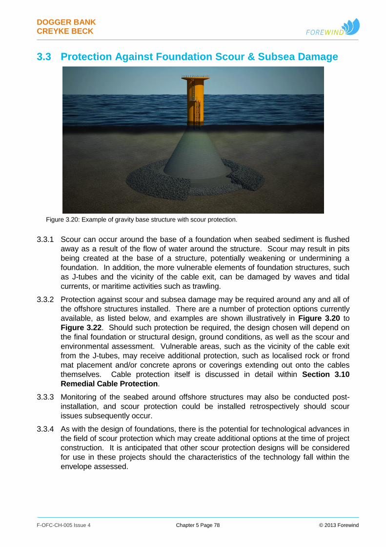
DOGGER BANK CREYKE BECK
F-OFC-CH-005 Issue 4 Chapter 5 Page 78 © 2013 Forewind
3.3 Protection Against Foundation Scour & Subsea Damage
Figure 3.20: Example of gravity base structure with scour protection.
3.3.1 Scour can occur around the base of a foundation when seabed sediment is flushed
away as a result of the flow of water around the structure. Scour may result in pits
being created at the base of a structure, potentially weakening or undermining a
foundation. In addition, the more vulnerable elements of foundation structures, such
as J-tubes and the vicinity of the cable exit, can be damaged by waves and tidal
currents, or maritime activities such as trawling.
3.3.2 Protection against scour and subsea damage may be required around any and all of
the offshore structures installed. There are a number of protection options currently
available, as listed below, and examples are shown illustratively in Figure 3.20 to
Figure 3.22. Should such protection be required, the design chosen will depend on
the final foundation or structural design, ground conditions, as well as the scour and
environmental assessment. Vulnerable areas, such as the vicinity of the cable exit
from the J-tubes, may receive additional protection, such as localised rock or frond
mat placement and/or concrete aprons or coverings extending out onto the cables
themselves. Cable protection itself is discussed in detail within Section 3.10
Remedial Cable Protection.
3.3.3 Monitoring of the seabed around offshore structures may also be conducted post-
installation, and scour protection could be installed retrospectively should scour
issues subsequently occur.
3.3.4 As with the design of foundations, there is the potential for technological advances in
the field of scour protection which may create additional options at the time of project
construction. It is anticipated that other scour protection designs will be considered
for use in these projects should the characteristics of the technology fall within the
envelope assessed.
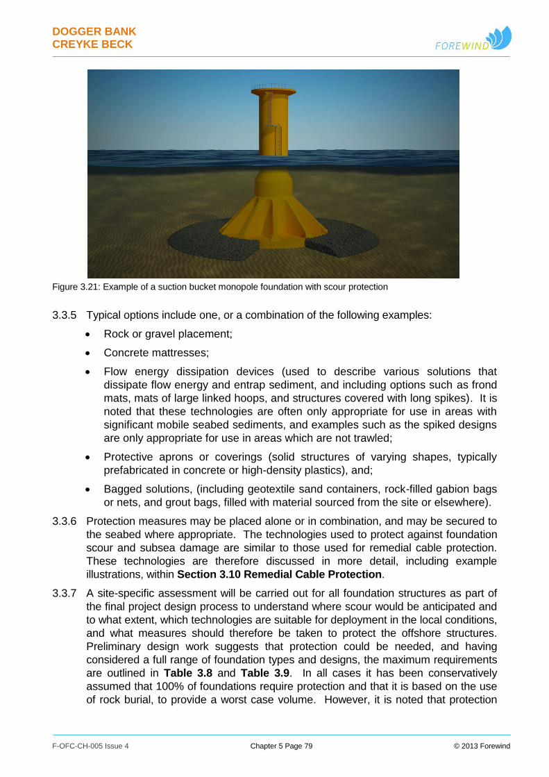
DOGGER BANK CREYKE BECK
F-OFC-CH-005 Issue 4 Chapter 5 Page 79 © 2013 Forewind
3.3.5 Typical options include one, or a combination of the following examples:
Rock or gravel placement;
Concrete mattresses;
Flow energy dissipation devices (used to describe various solutions that
dissipate flow energy and entrap sediment, and including options such as frond
mats, mats of large linked hoops, and structures covered with long spikes). It is
noted that these technologies are often only appropriate for use in areas with
significant mobile seabed sediments, and examples such as the spiked designs
are only appropriate for use in areas which are not trawled;
Protective aprons or coverings (solid structures of varying shapes, typically
prefabricated in concrete or high-density plastics), and;
Bagged solutions, (including geotextile sand containers, rock-filled gabion bags
or nets, and grout bags, filled with material sourced from the site or elsewhere).
3.3.6 Protection measures may be placed alone or in combination, and may be secured to
the seabed where appropriate. The technologies used to protect against foundation
scour and subsea damage are similar to those used for remedial cable protection.
These technologies are therefore discussed in more detail, including example
illustrations, within Section 3.10 Remedial Cable Protection.
3.3.7 A site-specific assessment will be carried out for all foundation structures as part of
the final project design process to understand where scour would be anticipated and
to what extent, which technologies are suitable for deployment in the local conditions,
and what measures should therefore be taken to protect the offshore structures.
Preliminary design work suggests that protection could be needed, and having
considered a full range of foundation types and designs, the maximum requirements
are outlined in Table 3.8 and Table 3.9. In all cases it has been conservatively
assumed that 100% of foundations require protection and that it is based on the use
of rock burial, to provide a worst case volume. However, it is noted that protection
Figure 3.21: Example of a suction bucket monopole foundation with scour protection

DOGGER BANK CREYKE BECK
F-OFC-CH-005 Issue 4 Chapter 5 Page 80 © 2013 Forewind
against scour or subsea damage may not be required for some foundation designs,
in some locations.
Table 3.8: Indicative wind turbine foundation subsea/scour protection parameters
Wind Turbine Size
Parameter Up to 4MW 6MW 10MW or greater
Maximum seabed footprint area
of subsea/scour protection per
foundation (excluding foundation
structure footprint) (m2)
3,777 3,777 3,777
Maximum seabed footprint area
of subsea/scour protection per
project (excluding foundation
structure footprint) (km2)
1.1331 0.7554 0.4532
Maximum volume of
subsea/scour protection material
per project (m3)
1,627,300 1,084,800 667,500
Table 3.9: Indicative offshore platform and meteorological station foundation subsea/scour protection parameters
Meteorological
Station
Offshore Platform Type
Parameter Collector Converter/
Accommodation
Maximum seabed footprint area
of subsea/scour protection per
foundation (excluding foundation
structure footprint) (m2)
3,777 8,742 8,742
Maximum seabed footprint area
of subsea/scour protection per
project (excluding foundation
structure footprint) (km2)
0.0188 0.0349 0.0262
Maximum volume of
subsea/scour protection material
per project (m3)
27,100 69,900 52,450
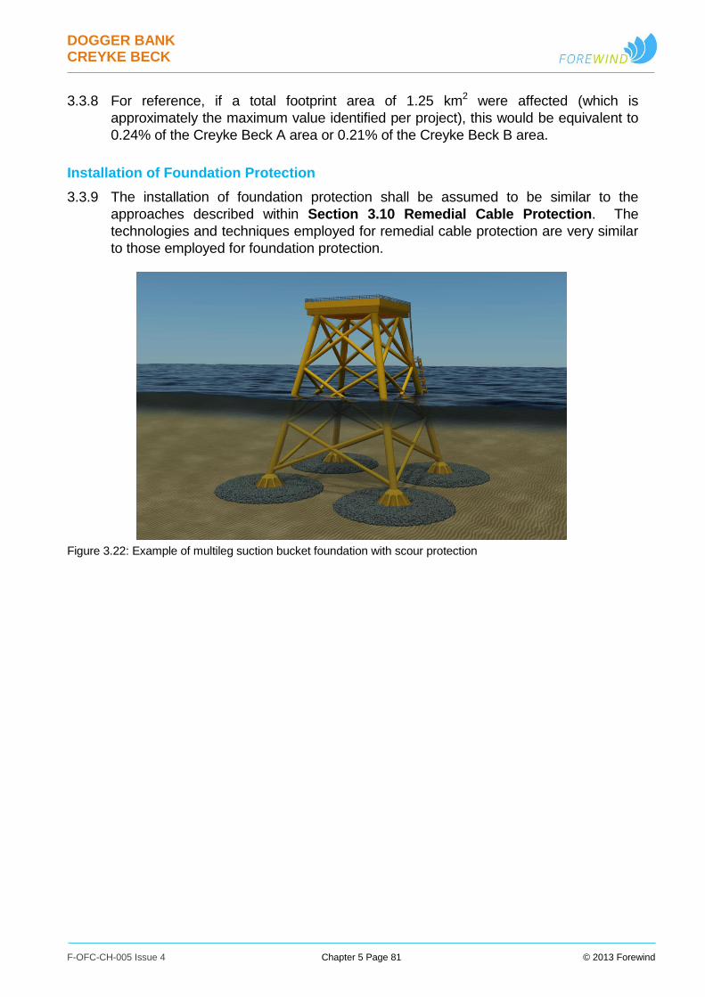
DOGGER BANK CREYKE BECK
F-OFC-CH-005 Issue 4 Chapter 5 Page 81 © 2013 Forewind
3.3.8 For reference, if a total footprint area of 1.25 km2 were affected (which is
approximately the maximum value identified per project), this would be equivalent to
0.24% of the Creyke Beck A area or 0.21% of the Creyke Beck B area.
Installation of Foundation Protection
3.3.9 The installation of foundation protection shall be assumed to be similar to the
approaches described within Section 3.10 Remedial Cable Protection. The
technologies and techniques employed for remedial cable protection are very similar
to those employed for foundation protection.
Figure 3.22: Example of multileg suction bucket foundation with scour protection
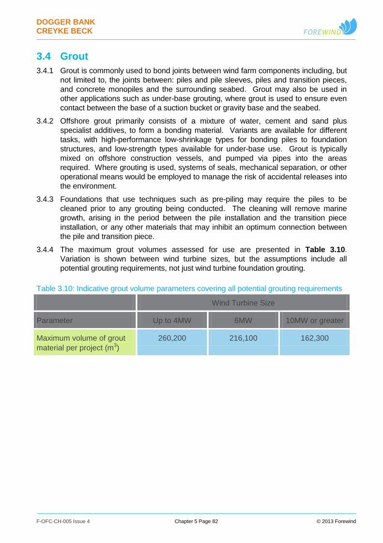
DOGGER BANK CREYKE BECK
F-OFC-CH-005 Issue 4 Chapter 5 Page 82 © 2013 Forewind
3.4 Grout
3.4.1 Grout is commonly used to bond joints between wind farm components including, but
not limited to, the joints between: piles and pile sleeves, piles and transition pieces,
and concrete monopiles and the surrounding seabed. Grout may also be used in
other applications such as under-base grouting, where grout is used to ensure even
contact between the base of a suction bucket or gravity base and the seabed.
3.4.2 Offshore grout primarily consists of a mixture of water, cement and sand plus
specialist additives, to form a bonding material. Variants are available for different
tasks, with high-performance low-shrinkage types for bonding piles to foundation
structures, and low-strength types available for under-base use. Grout is typically
mixed on offshore construction vessels, and pumped via pipes into the areas
required. Where grouting is used, systems of seals, mechanical separation, or other
operational means would be employed to manage the risk of accidental releases into
the environment.
3.4.3 Foundations that use techniques such as pre-piling may require the piles to be
cleaned prior to any grouting being conducted. The cleaning will remove marine
growth, arising in the period between the pile installation and the transition piece
installation, or any other materials that may inhibit an optimum connection between
the pile and transition piece.
3.4.4 The maximum grout volumes assessed for use are presented in Table 3.10.
Variation is shown between wind turbine sizes, but the assumptions include all
potential grouting requirements, not just wind turbine foundation grouting.
Table 3.10: Indicative grout volume parameters covering all potential grouting requirements
Wind Turbine Size
Parameter Up to 4MW 6MW 10MW or greater
Maximum volume of grout
material per project (m3)
260,200 216,100 162,300
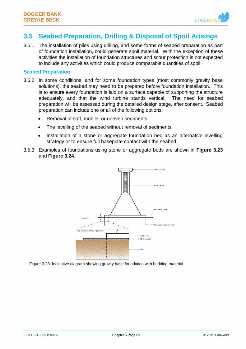
DOGGER BANK CREYKE BECK
F-OFC-CH-005 Issue 4 Chapter 5 Page 83 © 2013 Forewind
3.5 Seabed Preparation, Drilling & Disposal of Spoil Arisings
3.5.1 The installation of piles using drilling, and some forms of seabed preparation as part
of foundation installation, could generate spoil material. With the exception of these
activities the installation of foundation structures and scour protection is not expected
to include any activities which could produce comparable quantities of spoil.
Seabed Preparation
3.5.2 In some conditions, and for some foundation types (most commonly gravity base
solutions), the seabed may need to be prepared before foundation installation. This
is to ensure every foundation is laid on a surface capable of supporting the structure
adequately, and that the wind turbine stands vertical. The need for seabed
preparation will be assessed during the detailed design stage, after consent. Seabed
preparation can include one or all of the following options:
Removal of soft, mobile, or uneven sediments.
The levelling of the seabed without removal of sediments.
Installation of a stone or aggregate foundation bed as an alternative levelling
strategy or to ensure full baseplate contact with the seabed.
3.5.3 Examples of foundations using stone or aggregate beds are shown in Figure 3.23
and Figure 3.24.
Figure 3.23: Indicative diagram showing gravity base foundation with bedding material

DOGGER BANK CREYKE BECK
F-OFC-CH-005 Issue 4 Chapter 5 Page 84 © 2013 Forewind
Figure 3.24: Indicative diagram showing gravity base foundation with shallow excavation filled with
bedding material
3.5.4 Seabed preparation would typically take place over an area slightly larger than the
base footprint of the foundation and could take a range of shapes depending on the
equipment used and the geometry of the foundation to be laid, for example
rectangular or circular. Seabed preparation involves mechanical levelling, typically
using suction dredging where sediments are to be moved or removed.
3.5.5 Other similar aggregate or subsea construction vessels are typically used for
installation of rock or gravel layers. The technology for preparing the seabed prior to
installation has been used previously for gravity base structures (for example at
Thornton Bank offshore wind farm, Belgium). The techniques used to install stone or
aggregate foundation beds are similar to those described in Section 3.10 Remedial
Cable Protection, and Section 3.3 Protection Against Foundation Scour &
Subsea Damage.
3.5.6 Seabed conditions for Dogger Bank Creyke Beck are such that only limited seabed
preparation is anticipated. Spoil volumes have therefore been developed on this
basis, although still providing realistic worst-case values, with parameters shown in
Table 3.11 and Table 3.12.
3.5.7 Disposal of arisings is discussed in association with the following section on drilling.
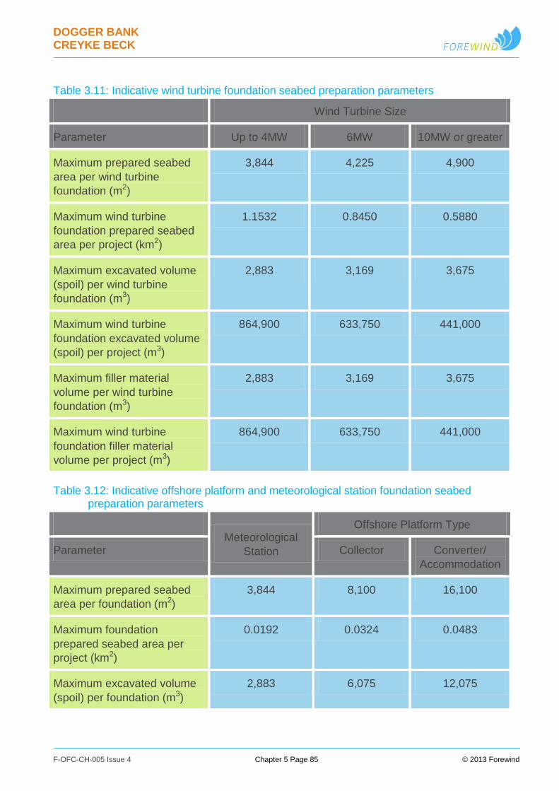
DOGGER BANK CREYKE BECK
F-OFC-CH-005 Issue 4 Chapter 5 Page 85 © 2013 Forewind
Table 3.11: Indicative wind turbine foundation seabed preparation parameters
Wind Turbine Size
Parameter Up to 4MW 6MW 10MW or greater
Maximum prepared seabed
area per wind turbine
foundation (m2)
3,844 4,225 4,900
Maximum wind turbine
foundation prepared seabed
area per project (km2)
1.1532 0.8450 0.5880
Maximum excavated volume
(spoil) per wind turbine
foundation (m3)
2,883 3,169 3,675
Maximum wind turbine
foundation excavated volume
(spoil) per project (m3)
864,900 633,750 441,000
Maximum filler material
volume per wind turbine
foundation (m3)
2,883 3,169 3,675
Maximum wind turbine
foundation filler material
volume per project (m3)
864,900 633,750 441,000
Table 3.12: Indicative offshore platform and meteorological station foundation seabed preparation parameters
Meteorological
Station
Offshore Platform Type
Parameter Collector Converter/
Accommodation
Maximum prepared seabed
area per foundation (m2)
3,844 8,100 16,100
Maximum foundation
prepared seabed area per
project (km2)
0.0192 0.0324 0.0483
Maximum excavated volume
(spoil) per foundation (m3)
2,883 6,075 12,075
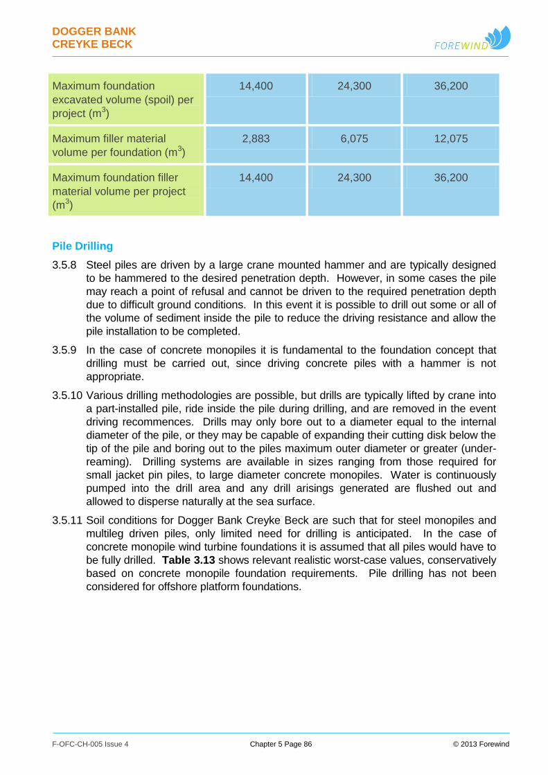
DOGGER BANK CREYKE BECK
F-OFC-CH-005 Issue 4 Chapter 5 Page 86 © 2013 Forewind
Maximum foundation
excavated volume (spoil) per
project (m3)
14,400 24,300 36,200
Maximum filler material
volume per foundation (m3)
2,883 6,075 12,075
Maximum foundation filler
material volume per project
(m3)
14,400 24,300 36,200
Pile Drilling
3.5.8 Steel piles are driven by a large crane mounted hammer and are typically designed
to be hammered to the desired penetration depth. However, in some cases the pile
may reach a point of refusal and cannot be driven to the required penetration depth
due to difficult ground conditions. In this event it is possible to drill out some or all of
the volume of sediment inside the pile to reduce the driving resistance and allow the
pile installation to be completed.
3.5.9 In the case of concrete monopiles it is fundamental to the foundation concept that
drilling must be carried out, since driving concrete piles with a hammer is not
appropriate.
3.5.10 Various drilling methodologies are possible, but drills are typically lifted by crane into
a part-installed pile, ride inside the pile during drilling, and are removed in the event
driving recommences. Drills may only bore out to a diameter equal to the internal
diameter of the pile, or they may be capable of expanding their cutting disk below the
tip of the pile and boring out to the piles maximum outer diameter or greater (under-
reaming). Drilling systems are available in sizes ranging from those required for
small jacket pin piles, to large diameter concrete monopiles. Water is continuously
pumped into the drill area and any drill arisings generated are flushed out and
allowed to disperse naturally at the sea surface.
3.5.11 Soil conditions for Dogger Bank Creyke Beck are such that for steel monopiles and
multileg driven piles, only limited need for drilling is anticipated. In the case of
concrete monopile wind turbine foundations it is assumed that all piles would have to
be fully drilled. Table 3.13 shows relevant realistic worst-case values, conservatively
based on concrete monopile foundation requirements. Pile drilling has not been
considered for offshore platform foundations.

DOGGER BANK CREYKE BECK
F-OFC-CH-005 Issue 4 Chapter 5 Page 87 © 2013 Forewind
Table 3.13: Indicative drill arising parameters
Wind Turbine Size
Parameter Up to 4MW 6MW 10MW or greater
Foundations potentially using
drilling
Wind turbine monopole foundations
Wind turbine multileg foundations
Maximum percentage of wind
turbine foundations
potentially using drilling (%)
100
Conservative average drill
arising volume per wind
turbine foundation (m3)
3,691 4,752 6,220
Maximum drill arising volume
for wind turbine foundations
per project (m3)
1,107,400 950,300 746,400
Disposal of Seabed Preparation and Drilling Spoil Arisings
3.5.12 It is proposed that any spoil arisings generated by seabed preparation or drilling
would be disposed of within the project area; near the location the material was
derived. The spoil materials will then be winnowed away by the natural wave and
tide driven processes. Some of the excavated volume may be re-used to meet some
or all of the requirements for ballast material required for structures such as gravity
bases, or filler material required for protection against scour and subsea damage
(such as geotextile sand containers).
3.5.13 It should be noted that the maximum project spoil volume presented in the table
above would be generated over the entire period of foundation installation. Spoil
generated would therefore be subject to constant erosion and dispersal over time
rather than representing one single large dispersal event.
DOGGER BANK CREYKE BECK
F-OFC-CH-005 Issue 4 Chapter 5 Page 88 © 2013 Forewind
3.6 Piling & Noise Modelling
Piling
3.6.1 Piling (also known as pile driving, or impact piling) involves a large hammer being
dropped, or typically driven, onto the top of a foundation pile, thereby driving it into
the ground. Piles may be held in place during piling by the foundation structure itself,
or by frames and pile grippers mounted on a vessel, or the seabed. In these cases
the piling frames maintain the pile orientation until it has been installed to a sufficient
depth to maintain its stability unaided.
3.6.2 Piling is commonly used to install steel monopiles and driven piles associated with
multileg foundations.
Soft Start
3.6.3 In line with Joint Nature Conservation Committee (JNCC) guidance, the piling
sequence will begin with a ‘soft start’ period, where the hammer energy and blow rate
are less than used during the main piling stage. Hammer energy is typically started
at around 10% of rated hammer energy and then ramped up over the duration of the
soft start to full power and blow rate.
Typical Piling Sequence
3.6.4 A typical piling sequence progresses as follows:
i. Notices to local diving groups, mariners and other relevant sea users are issued
informing them of piling times, locations, expected durations, exclusion zones, etc;
ii. Guard vessels may be deployed around the piling area to restrict access of sea
users into the piling safety zone;
iii. Deterrent devices (such as pingers and seal scarers) may be deployed to allow
marine mammals an opportunity to move away from the area of noise. This is
discussed in greater detail within Chapter 14 Marine Mammals;
iv. Pile is lifted into position, typically within a pile gripper on the vessel and is
positioned on the seabed (using a pile template or similar if required for multileg
foundations) with pile weight providing initial seabed penetration;
v. Piling soft start commences, and ramps up to rated hammer energy and blow rate;
vi. Main piling stage is reached, with hammering at maximum energy and blow rate;
vii. Depending on local geology and technical and economic considerations, drilling
may be required, in which case piling would stop to allow this to be undertaken;
viii. Piling would then continue until the desired penetration has been achieved and pile
installation is complete;
ix. Vessel either installs transition pieces or foundation structure onto the installed pile,
or moves to the next piling location to begin again.
3.6.5 Driving a single pile could take less than an hour if soil conditions are favourable, but
significantly longer if the ground conditions are more challenging. Piling may take
place at any time of day or night, assuming appropriate procedures are in place, and
may not be continuous for a single pile; the active piling time may be split across a
longer period, particularly in the event of mechanical breakdown, or drilling being

DOGGER BANK CREYKE BECK
F-OFC-CH-005 Issue 4 Chapter 5 Page 89 © 2013 Forewind
required. The key parameters considered for piling (across all foundation types) are
listed in Table 3.14 and Table 3.15.
Table 3.14: Wind turbine and meteorological station foundation indicative piling parameters
Wind Turbine Size
Parameter Up to 4MW (and
Meteorological
Stations)
6MW 10MW or greater
Monopole Foundations
Monopole - maximum
driven pile diameter (m)
10 10 10
Monopole - maximum
hammer driving energy (kJ)
2,300 3,000 3,000
Maximum blows per minute
per pile
40 40 40
Indicative soft start duration
per pile (hr)
0.5 0.5 0.5
Indicative active piling time
per foundation excluding
soft start (hr)
3 3 3
Indicative total blows per
pile – including soft start
8,400 8,400 8,400
Multileg Foundations
Multileg - maximum driven
pile diameter (m)
3.5 3.5 3.5
Multileg - maximum number
of driven piles per
foundation
6
(up to a maximum
of 1200 wind
turbine multileg
piles per project)
6 6
Multileg - maximum
hammer driving energy (kJ)
1,900 2,300 2,300

DOGGER BANK CREYKE BECK
F-OFC-CH-005 Issue 4 Chapter 5 Page 90 © 2013 Forewind
Maximum blows per minute
per pile
40 40 40
Indicative soft start duration
per pile (hr)
0.5 0.5 0.5
Indicative active piling time
per foundation excluding
soft start (hr)
18 18 18
Indicative total blows per
pile – including soft start
8,400 8,400 8,400
Table 3.15: Offshore platform foundation indicative piling parameters
Offshore Platform Types
Parameter Collector Converter Accommodation
Maximum number of
driven piles per foundation
24 24 24
Maximum driven pile
diameter (m)
2.744 2.744 2.744
Maximum hammer driving
energy (kJ)
1,900 1,900 1,900
Maximum blows per
minute per pile
40 40 40
Indicative soft start
duration per pile (hr)
0.5 0.5 0.5
Indicative active piling time
per foundation excluding
soft start (hr)
72 72 72
Indicative total blows per
pile – including soft start
8,400 8,400 8,400
3.6.6 It is noted that although the stated pile diameters do not vary between wind turbine
sizes, other characteristics may vary (such as the water depth feasible for
deployment, the maximum feasible wind turbine loads, and the pile depth). The
potential for variation in pile depth, in particular, is a driver for the variations in
maximum hammer driving energy.
DOGGER BANK CREYKE BECK
F-OFC-CH-005 Issue 4 Chapter 5 Page 91 © 2013 Forewind
Vibration Piling
3.6.7 An alternative methodology to standard impact piling involves using vibrodriver
devices in place of impact hammers, to both drive and extract piles. A typical
vibrodriver contains one or more pairs of eccentrically-rotating weights which spin in
opposite directions to generate ‘up and down’ forces (vertical vibrations), while
cancelling out unwanted vibrations in other directions. Vibration piling is then based
on the principle of reducing the friction between the soil and the pile using this
vibration.
3.6.8 Vibration piling is not yet a proven technique for offshore wind foundations, it is not
yet considered viable in all soil conditions and for all foundation types, and can
normally only be used for part of the installation of a pile – with impact piling typically
required to complete the final installation of each pile.
3.6.9 Vibration piling may be considered for use where the local geological conditions and
selected foundation technologies allow.
Non-Piled Foundation Installation
3.6.10 Noise generated by other foundation types and installation techniques will be
significantly less than that caused by driven piling. Installation of suction, gravity,
jack-up, and screw pile foundations requires only relatively quiet machinery (pumps
and motors), and inherently include no activities which generate levels of noise
comparable with impact piling.

DOGGER BANK CREYKE BECK
F-OFC-CH-005 Issue 4 Chapter 5 Page 92 © 2013 Forewind
Noise Modelling
3.6.11 Underwater noise, including construction and operational noise, has been assessed
as part of the environmental impact assessment. Full details and results of the noise
modelling undertaken are contained within Appendix 5.A Dogger Bank Creyke
Beck Underwater Noise Technical Report (National Physical Laboratory, 2013).
Background to Underwater Acoustics
3.6.12 Underwater sound can be described as a pressure wave travelling through water.
The low absorption properties of water allow sound to travel large distances in the
ocean, particularly evident for lower frequency sounds (Kinsler et al. 1982, Kaye and
Laby 2004). This low absorption of pressure waves also results in a greater sound
transmission speed of 1,500m/s in water compared to 340m/s in air.
3.6.13 The amplitude of the sound can be described in terms of the sound pressure, where
the unit of pressure is the Pascal (Pa) or newton per square metre (N/m2). However,
by convention, sound levels are expressed in decibels (dB) relative to a reference
pressure, which is 1 μPa for underwater sound.
3.6.14 Metrics most commonly used to describe the underwater sound in impact piling in the
UK include Sound Exposure Level (SEL) and peak-to-peak pressure level. The
Sound Exposure Level is a measure of the pulse energy content and is calculated
from the integral of the squared sound pressure over the duration of the pulse. The
SEL can also be expressed in dB notation referenced to 1 μPa2•s. For a specific
pulse or waveform, the peak pressure level, PPL, is defined as the zero to peak
pressure of the pulse and can be expressed as the zero-to-peak pressure level (or
peak pressure level, PPL) in units of dB re 1 μPa.
3.6.15 Sound Pressure Level (SPL) is another metric used in underwater acoustics, typically
for describing the level of continuous type noise sources, such as from shipping or
turbine operation.
3.6.16 Propagation Loss (PL) or Transmission Loss (TL) is the reduction of the sound level
as a function of distance from an acoustic source. This is primarily due to
geometrical spreading, sound absorption in the water and losses into the seabed or
other boundaries.
3.6.17 The received level (RL) is the acoustic pressure measured by a hydrophone at some
distance away from a sound source. It is also considered to be the sound pressure
which arrives at any acoustic receptor which is exposed to a sound. The received
level might be expressed in a number of ways, for example as a sound pressure level
(dB re 1 μPa) or a sound exposure level (dB re 1 μPa2•s).
Ambient Noise
3.6.18 There are numerous ambient noise sources in the Dogger Bank Creyke Beck area,
both natural and anthropogenic. Natural noise sources will likely be from the wind
(sea-state), rain and biological noise, dominated by the interaction of wind with the
sea surface. Noise generated by the interaction of wind with the sea surface is likely
to be the dominant natural contributor to ambient noise at the Dogger Bank Zone,
and will range from a few hertz to a few tens of kilohertz. Biological contribution to

DOGGER BANK CREYKE BECK
F-OFC-CH-005 Issue 4 Chapter 5 Page 93 © 2013 Forewind
ambient noise (such as marine mammal vocalisations and sounds made by fish) may
also be significant.
3.6.19 Anthropogenic contributors to ambient noise levels in the North Sea include shipping
(e.g. fishing, cargo, cruise ship, ferries and aggregate extraction/dredging) and the oil
and gas industry. Dredging vessels may be noisier and produce noise at higher
frequencies than other commercial vessel types transiting nearby (Robinson et al.
2011).
3.6.20 Tidal changes in shallower areas (<20m) of Creyke Beck A and Creyke Beck B may
result in ambient noise variations due to changes in the propagation environment,
which changes with depth. Sand banks at low tide can elevate propagation loss of
lower frequency sounds in particular, resulting in a reduction in ambient noise levels
detected in the surrounding area.
3.6.21 The potential impact of noise on marine receptors (namely marine mammals and
fish) during each phase of the wind farm development (i.e. construction, operation
and decommissioning) has been assessed as part of this EIA. The effects of noise
transmission in water and ambient noise levels on these receptors are discussed in
further detail in Chapter 13 Fish and Shellfish Ecology and Chapter 14 Marine
Mammals.
Construction Noise (Foundation Installation)
3.6.22 The installation of foundation systems, namely those which rely on impact piling are
considered a major source of noise, resulting in significant noise levels.
3.6.23 Impact piling is considered a transient activity which is only likely to occur
concurrently at a small number of locations within the wind farm area. Assuming the
concurrent construction of two Creyke Beck projects and two Teesside projects, it is
anticipated that a maximum of eight piling vessels could be in operation at the same
time across the Dogger Bank Zone. During this phase, it is assumed a maximum of
two piling vessels will be operating in each of the four projects with a 1500m
separation between the two vessels in each project area; and a likely much larger
separation between projects (tens of km). The key parameters considered for piling
are listed in Table 3.14.
3.6.24 During the piling process, airborne noise is created by the hammer, partly as a result
of the impact of the hammer with the pile. The energy imposed on the pile by the
hammer also creates significant underwater noise as the pile distorts due to the
compressive, flexural and other complex waves travelling down the pile during each
‘blow’. Due to the low absorption of pressure waves in the surrounding water
column, these waterborne waves are the principle contributor to underwater noise
during foundation installation (Subacoustech 2011).
3.6.25 Larger monopile foundations require higher energy hammers than alternative
foundation designs, such as jackets, which utilise smaller diameter pin piles. Due to
this greater hammer energy, larger monopiles are likely to result in higher noise
levels during installation (Nehls et al. 2007). The peak noise levels generated by the
installation of jacket foundations are thus generally lower than monopile foundations
due to the smaller hammer energy, however the total time required for installation
DOGGER BANK CREYKE BECK
F-OFC-CH-005 Issue 4 Chapter 5 Page 94 © 2013 Forewind
can be longer. Therefore, although the zone of impact may be smaller during pin pile
installation, the disturbance may be present for a longer time period. The use of
jacket foundations that require lower hammer blow energies, assuming that the total
time to construct the wind farm is not increased significantly compared to the use of
monopile foundations could be considered to have a reduced impact on hearing
sensitive marine life.
3.6.26 The dimensions of the pile are not considered to have a significant effect on the noise
energy generated during installation. The noise resulting from a monopile using a
given hammer energy would be expected to be the same as that from a smaller
diameter pin-pile using the same hammer energy.
3.6.27 The underwater noise due to impact piling is known to result in significant peak
pressure levels and sound exposure levels and is distinguishable above ambient
noise over distances of several tens of kilometres from the source (Thomsen et al.
2006, Nedwell et al. 2007).
3.6.28 The use of soft-start systems (involving a gradual ramping up of the hammer strike
energy) is widely adopted as a mitigation measure as it enables animals to move
away from the sound source before it reaches the maximum noise levels. The use of
embedded mitigation such as this is now considered a prerequisite for offshore
impact piling activities in the North Sea.
Operational Noise
3.6.29 During the operational phase of a wind farm development, the principle underwater
noise source is mechanically generated vibration from the motion of the wind turbine,
transmitted through the support structure and foundation into the surrounding water
(Nedwell et al. 2003).
3.6.30 Underwater noise from an operational turbine mainly originates from the gearbox and
the generator and has particular tonal characteristics (Madsen et al. 2005, Tougaard
and Henriksen 2009). Operational noise from the wind turbines would be present for
the operational life of the wind farm and will contribute to the ambient noise in the
region. Noise from the operational wind turbines is not expected to noticeably
increase ambient noise beyond a few kilometres from the boundary of the wind farm.
3.6.31 Considering the operational wind turbine noise of the wind farm and any associated
service vessels, the ambient noise levels within the site would be expected to be
lower than those present in the vicinity of the shipping lanes both to the north and
south.
Modelling approach
3.6.32 For this noise assessment, a propagation model was developed based on an energy
flux approach, providing SEL and peak pressure received level outputs as a function
of range away from each modelled location, whilst accounting for seabed properties
and varying bathymetry. This approach was used to model noise propagation during
both the foundation installation phase and wind farm operation.
3.6.33 A range of hammer energies were modelled from soft-start up to the maximum
hammer energy expected for each turbine size and foundation type. The maximum
hammer energy and respective initial soft-start energy assumed in each case are

DOGGER BANK CREYKE BECK
F-OFC-CH-005 Issue 4 Chapter 5 Page 95 © 2013 Forewind
summarised in Table 3.14. An initial 300kJ hammer blow energy was used to
represent the highest expected soft-start hammer energy at the onset of piling.
3.6.34 To illustrate the total spatial extent of the potential impact ranges resulting from the
underwater noise during the construction phase, the sound propagation was
modelled at various locations along the project boundaries of Creyke Beck A and
Creyke Beck B. The maximum noise level received at every location around each
project was then calculated to show the construction noise footprint associated with
each project.
3.6.35 For each individually modelled piling event, a sound propagation map was obtained
showing the noise level as a two-dimensional function of range. The impact piling
underwater noise modelling was carried out using an energy source level which
scales linearly with the hammer energy.
3.6.36 Injury and behaviour criteria were applied to the outputs of the underwater noise
modelling to predict the potential impact ranges for Creyke Beck A and Creyke Beck
B. These are described in detail in Chapter 13 Fish and Shellfish Ecology and
Chapter 14 Marine Mammals.
Outline Results of the Study
3.6.37 The noise assessment predicts the likely underwater noise levels generated during
construction and operation at Dogger Bank Creyke Beck. Based on the modelling
conducted it was observed that:
The estimated maximum sound exposure level (unweighted pulse SEL) during
impact piling activities is in the range of 145 – 150 dB re 1μPa2•s, 20km from
the source;
The estimated maximum sound pressure level (SPL (RMS)) during the
operational phase of the wind farm is in the range of 110 – 115 dB re 1μPa, 1km
from the source;
There is considerable variation in noise propagation across Creyke Beck A and
Creyke Beck B and the surrounding areas due to variations in bathymetry, with
the most efficient sound propagation conditions occurring a few tens of
kilometres west of Creyke Beck A and along the western and northern edges of
Creyke Beck B;
A piling noise propagation map, based on a representative location within
Creyke Beck A, is shown in Figure 3.25, and a noise map for operational noise
at Creyke Beck A is shown in Figure 3.26.
3.6.38 Full results are contained within Appendix 5.A Dogger Bank Creyke Beck
Underwater Noise Technical Report (National Physical Laboratory, 2013), and the
impact assessments associated with these results are primarily discussed within
Chapter 13 Fish and Shellfish Ecology and Chapter 14 Marine Mammals.
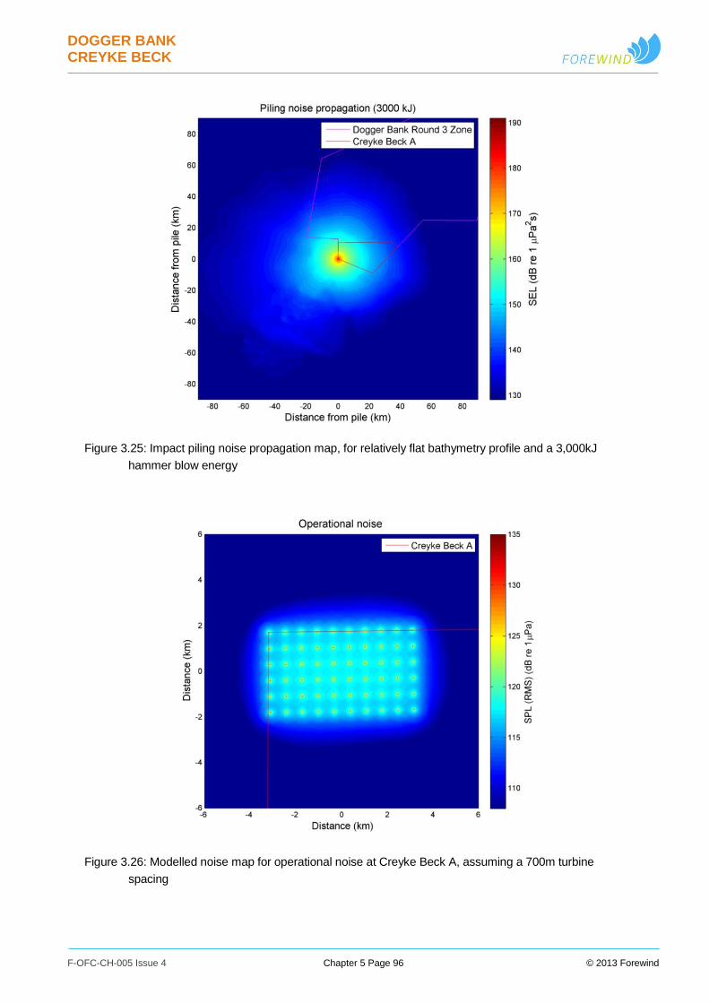
DOGGER BANK CREYKE BECK
F-OFC-CH-005 Issue 4 Chapter 5 Page 96 © 2013 Forewind
Figure 3.25: Impact piling noise propagation map, for relatively flat bathymetry profile and a 3,000kJ
hammer blow energy
Figure 3.26: Modelled noise map for operational noise at Creyke Beck A, assuming a 700m turbine
spacing
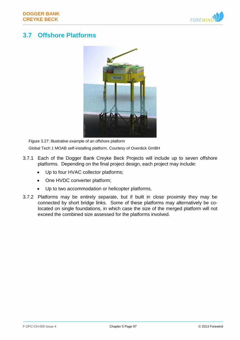
DOGGER BANK CREYKE BECK
F-OFC-CH-005 Issue 4 Chapter 5 Page 97 © 2013 Forewind
3.7 Offshore Platforms
Figure 3.27: Illustrative example of an offshore platform
Global Tech 1 MOAB self-installing platform. Courtesy of Overdick GmBH
3.7.1 Each of the Dogger Bank Creyke Beck Projects will include up to seven offshore
platforms. Depending on the final project design, each project may include:
Up to four HVAC collector platforms;
One HVDC converter platform;
Up to two accommodation or helicopter platforms.
3.7.2 Platforms may be entirely separate, but if built in close proximity they may be
connected by short bridge links. Some of these platforms may alternatively be co-
located on single foundations, in which case the size of the merged platform will not
exceed the combined size assessed for the platforms involved.
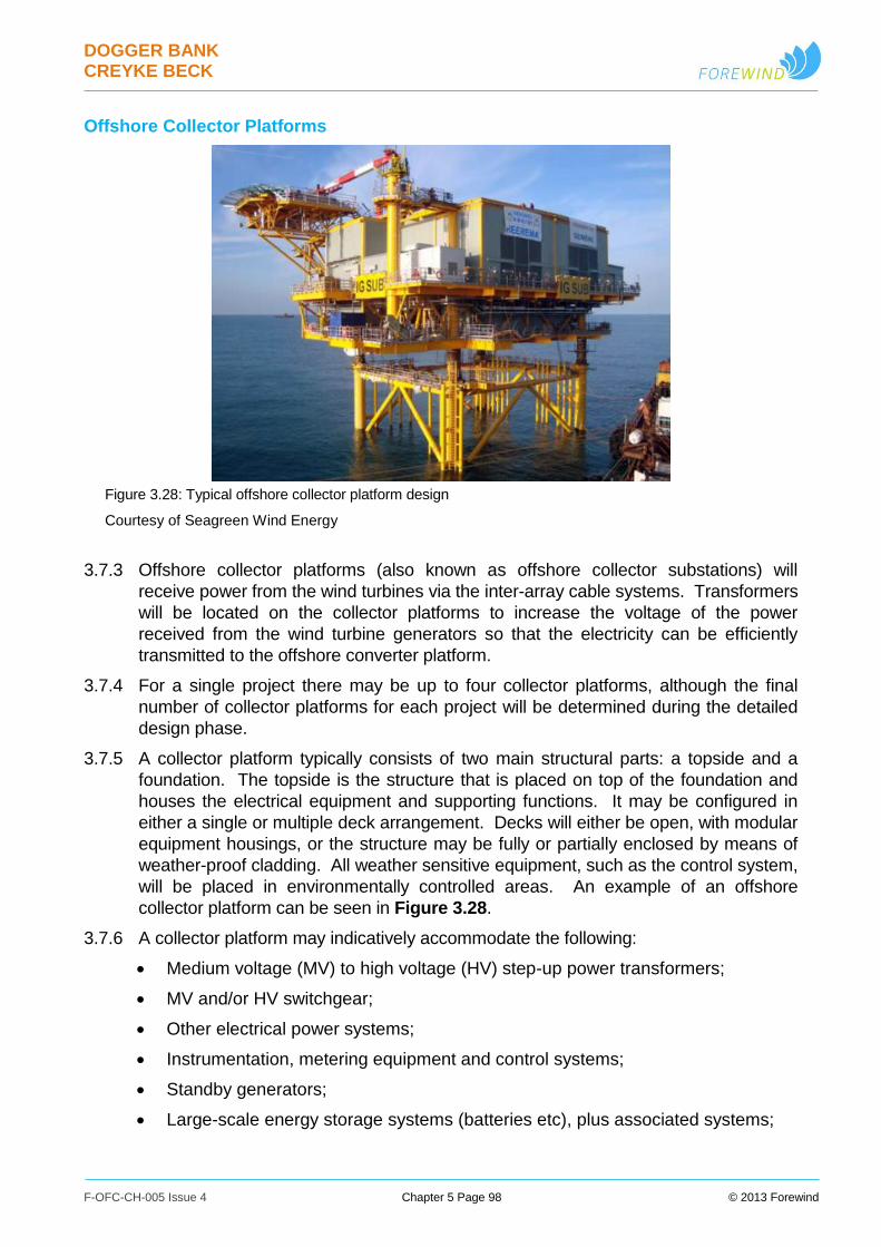
DOGGER BANK CREYKE BECK
F-OFC-CH-005 Issue 4 Chapter 5 Page 98 © 2013 Forewind
Offshore Collector Platforms
Figure 3.28: Typical offshore collector platform design
Courtesy of Seagreen Wind Energy
3.7.3 Offshore collector platforms (also known as offshore collector substations) will
receive power from the wind turbines via the inter-array cable systems. Transformers
will be located on the collector platforms to increase the voltage of the power
received from the wind turbine generators so that the electricity can be efficiently
transmitted to the offshore converter platform.
3.7.4 For a single project there may be up to four collector platforms, although the final
number of collector platforms for each project will be determined during the detailed
design phase.
3.7.5 A collector platform typically consists of two main structural parts: a topside and a
foundation. The topside is the structure that is placed on top of the foundation and
houses the electrical equipment and supporting functions. It may be configured in
either a single or multiple deck arrangement. Decks will either be open, with modular
equipment housings, or the structure may be fully or partially enclosed by means of
weather-proof cladding. All weather sensitive equipment, such as the control system,
will be placed in environmentally controlled areas. An example of an offshore
collector platform can be seen in Figure 3.28.
3.7.6 A collector platform may indicatively accommodate the following:
Medium voltage (MV) to high voltage (HV) step-up power transformers;
MV and/or HV switchgear;
Other electrical power systems;
Instrumentation, metering equipment and control systems;
Standby generators;
Large-scale energy storage systems (batteries etc), plus associated systems;
DOGGER BANK CREYKE BECK
F-OFC-CH-005 Issue 4 Chapter 5 Page 99 © 2013 Forewind
Auxiliary and uninterruptible power supply systems;
Navigation, aviation and safety marking and lighting;
Helicopter landing facilities;
Systems for vessel access and/or retrieval;
Vessel and helicopter refuelling facilities;
Potable water;
Black water separation;
Storage (including stores, fuel, and spares);
Offshore accommodation and mess facilities
Cranes; and
Communication systems and control hub facilities.
3.7.7 The final capacity and dimensions for collector platforms of the projects will be
determined through detailed design. In order to allow for future designs with large
capacities on a single platform, larger dimensions than seen previously have been
included into the design envelope. Indicative collector platform dimensions are
summarised in Table 3.16.
Table 3.16: Indicative collector platform parameters
Parameter Offshore Collector Platform
Number of platforms per project Up to 4
Collector system side nominal voltage range
(kV)
33 to 72.5
Inter-platform side nominal voltage range
(kV)
132 to 400
Indicative width (m) 75
Indicative length (m) 75
Indicative height above HAT (m) 85
Indicative topside weight (t) 3,000 - 5,000
3.7.8 Foundations considered for offshore collector platforms include gravity and multileg
options. The preferred platform and foundation concept will be confirmed following
detailed design work. Offshore platform foundations are detailed in Section 3.2
Offshore Structure Foundations.
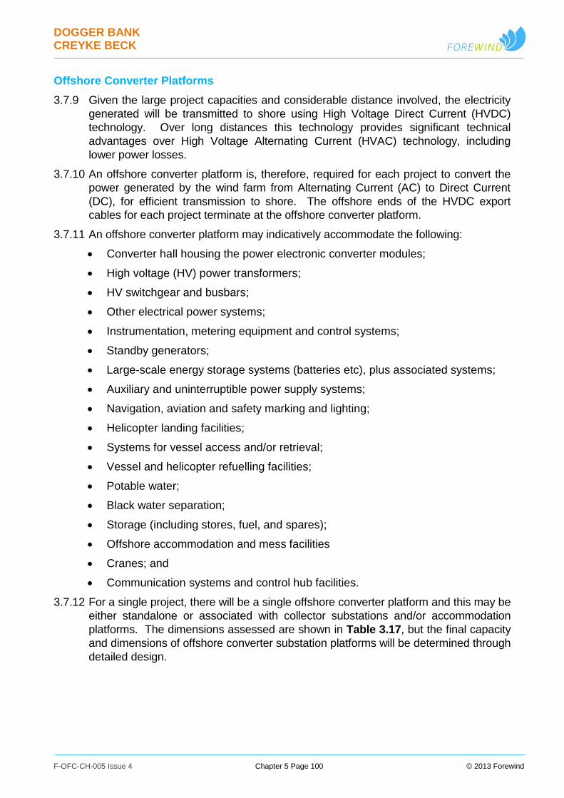
DOGGER BANK CREYKE BECK
F-OFC-CH-005 Issue 4 Chapter 5 Page 100 © 2013 Forewind
Offshore Converter Platforms
3.7.9 Given the large project capacities and considerable distance involved, the electricity
generated will be transmitted to shore using High Voltage Direct Current (HVDC)
technology. Over long distances this technology provides significant technical
advantages over High Voltage Alternating Current (HVAC) technology, including
lower power losses.
3.7.10 An offshore converter platform is, therefore, required for each project to convert the
power generated by the wind farm from Alternating Current (AC) to Direct Current
(DC), for efficient transmission to shore. The offshore ends of the HVDC export
cables for each project terminate at the offshore converter platform.
3.7.11 An offshore converter platform may indicatively accommodate the following:
Converter hall housing the power electronic converter modules;
High voltage (HV) power transformers;
HV switchgear and busbars;
Other electrical power systems;
Instrumentation, metering equipment and control systems;
Standby generators;
Large-scale energy storage systems (batteries etc), plus associated systems;
Auxiliary and uninterruptible power supply systems;
Navigation, aviation and safety marking and lighting;
Helicopter landing facilities;
Systems for vessel access and/or retrieval;
Vessel and helicopter refuelling facilities;
Potable water;
Black water separation;
Storage (including stores, fuel, and spares);
Offshore accommodation and mess facilities
Cranes; and
Communication systems and control hub facilities.
3.7.12 For a single project, there will be a single offshore converter platform and this may be
either standalone or associated with collector substations and/or accommodation
platforms. The dimensions assessed are shown in Table 3.17, but the final capacity
and dimensions of offshore converter substation platforms will be determined through
detailed design.
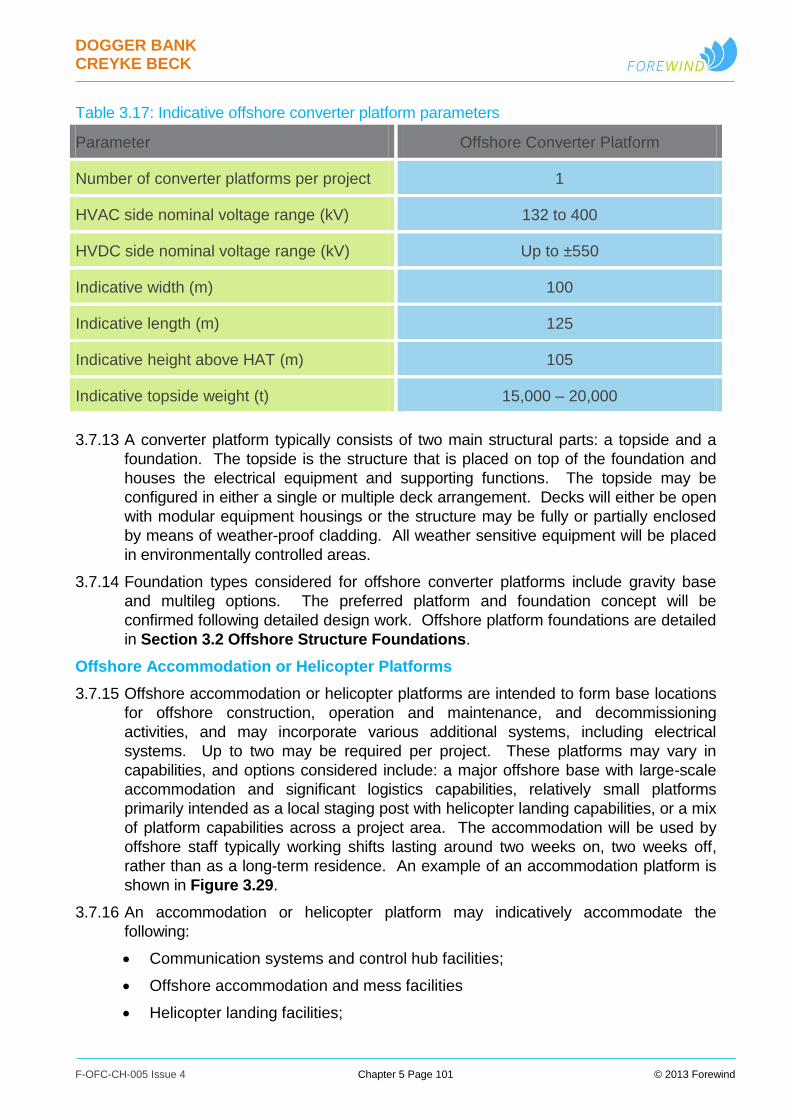
DOGGER BANK CREYKE BECK
F-OFC-CH-005 Issue 4 Chapter 5 Page 101 © 2013 Forewind
Table 3.17: Indicative offshore converter platform parameters
Parameter Offshore Converter Platform
Number of converter platforms per project 1
HVAC side nominal voltage range (kV) 132 to 400
HVDC side nominal voltage range (kV) Up to ±550
Indicative width (m) 100
Indicative length (m) 125
Indicative height above HAT (m) 105
Indicative topside weight (t) 15,000 – 20,000
3.7.13 A converter platform typically consists of two main structural parts: a topside and a
foundation. The topside is the structure that is placed on top of the foundation and
houses the electrical equipment and supporting functions. The topside may be
configured in either a single or multiple deck arrangement. Decks will either be open
with modular equipment housings or the structure may be fully or partially enclosed
by means of weather-proof cladding. All weather sensitive equipment will be placed
in environmentally controlled areas.
3.7.14 Foundation types considered for offshore converter platforms include gravity base
and multileg options. The preferred platform and foundation concept will be
confirmed following detailed design work. Offshore platform foundations are detailed
in Section 3.2 Offshore Structure Foundations.
Offshore Accommodation or Helicopter Platforms
3.7.15 Offshore accommodation or helicopter platforms are intended to form base locations
for offshore construction, operation and maintenance, and decommissioning
activities, and may incorporate various additional systems, including electrical
systems. Up to two may be required per project. These platforms may vary in
capabilities, and options considered include: a major offshore base with large-scale
accommodation and significant logistics capabilities, relatively small platforms
primarily intended as a local staging post with helicopter landing capabilities, or a mix
of platform capabilities across a project area. The accommodation will be used by
offshore staff typically working shifts lasting around two weeks on, two weeks off,
rather than as a long-term residence. An example of an accommodation platform is
shown in Figure 3.29.
3.7.16 An accommodation or helicopter platform may indicatively accommodate the
following:
Communication systems and control hub facilities;
Offshore accommodation and mess facilities
Helicopter landing facilities;
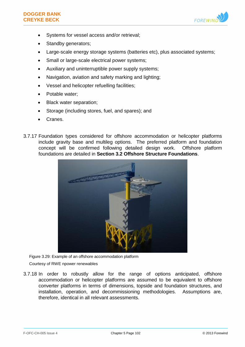
DOGGER BANK CREYKE BECK
F-OFC-CH-005 Issue 4 Chapter 5 Page 102 © 2013 Forewind
Systems for vessel access and/or retrieval;
Standby generators;
Large-scale energy storage systems (batteries etc), plus associated systems;
Small or large-scale electrical power systems;
Auxiliary and uninterruptible power supply systems;
Navigation, aviation and safety marking and lighting;
Vessel and helicopter refuelling facilities;
Potable water;
Black water separation;
Storage (including stores, fuel, and spares); and
Cranes.
3.7.17 Foundation types considered for offshore accommodation or helicopter platforms
include gravity base and multileg options. The preferred platform and foundation
concept will be confirmed following detailed design work. Offshore platform
foundations are detailed in Section 3.2 Offshore Structure Foundations.
Figure 3.29: Example of an offshore accommodation platform
Courtesy of RWE npower renewables
3.7.18 In order to robustly allow for the range of options anticipated, offshore
accommodation or helicopter platforms are assumed to be equivalent to offshore
converter platforms in terms of dimensions, topside and foundation structures, and
installation, operation, and decommissioning methodologies. Assumptions are,
therefore, identical in all relevant assessments.

DOGGER BANK CREYKE BECK
F-OFC-CH-005 Issue 4 Chapter 5 Page 103 © 2013 Forewind
Table 3.18: Indicative accommodation or helicopter platform parameters
Parameter Offshore Accommodation or Helicopter
Platforms
Number of platforms per project Up to 2
Dimensions, structures, and methodologies As for converter platforms (see Table 3.17)
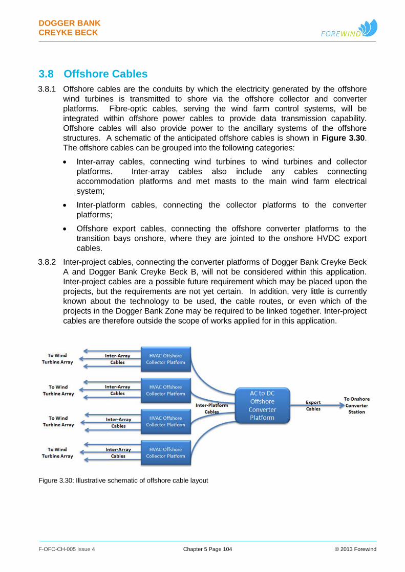
DOGGER BANK CREYKE BECK
F-OFC-CH-005 Issue 4 Chapter 5 Page 104 © 2013 Forewind
3.8 Offshore Cables
3.8.1 Offshore cables are the conduits by which the electricity generated by the offshore
wind turbines is transmitted to shore via the offshore collector and converter
platforms. Fibre-optic cables, serving the wind farm control systems, will be
integrated within offshore power cables to provide data transmission capability.
Offshore cables will also provide power to the ancillary systems of the offshore
structures. A schematic of the anticipated offshore cables is shown in Figure 3.30.
The offshore cables can be grouped into the following categories:
Inter-array cables, connecting wind turbines to wind turbines and collector
platforms. Inter-array cables also include any cables connecting
accommodation platforms and met masts to the main wind farm electrical
system;
Inter-platform cables, connecting the collector platforms to the converter
platforms;
Offshore export cables, connecting the offshore converter platforms to the
transition bays onshore, where they are jointed to the onshore HVDC export
cables.
3.8.2 Inter-project cables, connecting the converter platforms of Dogger Bank Creyke Beck
A and Dogger Bank Creyke Beck B, will not be considered within this application.
Inter-project cables are a possible future requirement which may be placed upon the
projects, but the requirements are not yet certain. In addition, very little is currently
known about the technology to be used, the cable routes, or even which of the
projects in the Dogger Bank Zone may be required to be linked together. Inter-project
cables are therefore outside the scope of works applied for in this application.
Figure 3.30: Illustrative schematic of offshore cable layout
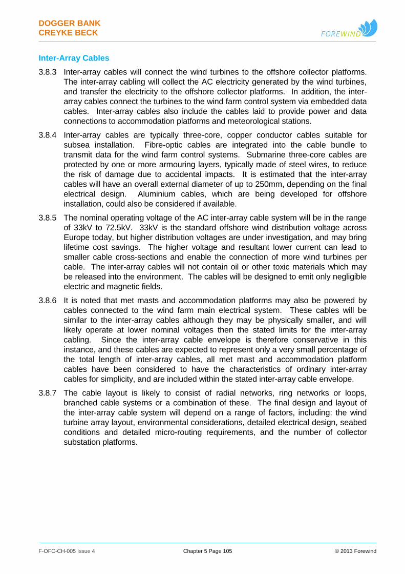
DOGGER BANK CREYKE BECK
F-OFC-CH-005 Issue 4 Chapter 5 Page 105 © 2013 Forewind
Inter-Array Cables
3.8.3 Inter-array cables will connect the wind turbines to the offshore collector platforms.
The inter-array cabling will collect the AC electricity generated by the wind turbines,
and transfer the electricity to the offshore collector platforms. In addition, the inter-
array cables connect the turbines to the wind farm control system via embedded data
cables. Inter-array cables also include the cables laid to provide power and data
connections to accommodation platforms and meteorological stations.
3.8.4 Inter-array cables are typically three-core, copper conductor cables suitable for
subsea installation. Fibre-optic cables are integrated into the cable bundle to
transmit data for the wind farm control systems. Submarine three-core cables are
protected by one or more armouring layers, typically made of steel wires, to reduce
the risk of damage due to accidental impacts. It is estimated that the inter-array
cables will have an overall external diameter of up to 250mm, depending on the final
electrical design. Aluminium cables, which are being developed for offshore
installation, could also be considered if available.
3.8.5 The nominal operating voltage of the AC inter-array cable system will be in the range
of 33kV to 72.5kV. 33kV is the standard offshore wind distribution voltage across
Europe today, but higher distribution voltages are under investigation, and may bring
lifetime cost savings. The higher voltage and resultant lower current can lead to
smaller cable cross-sections and enable the connection of more wind turbines per
cable. The inter-array cables will not contain oil or other toxic materials which may
be released into the environment. The cables will be designed to emit only negligible
electric and magnetic fields.
3.8.6 It is noted that met masts and accommodation platforms may also be powered by
cables connected to the wind farm main electrical system. These cables will be
similar to the inter-array cables although they may be physically smaller, and will
likely operate at lower nominal voltages then the stated limits for the inter-array
cabling. Since the inter-array cable envelope is therefore conservative in this
instance, and these cables are expected to represent only a very small percentage of
the total length of inter-array cables, all met mast and accommodation platform
cables have been considered to have the characteristics of ordinary inter-array
cables for simplicity, and are included within the stated inter-array cable envelope.
3.8.7 The cable layout is likely to consist of radial networks, ring networks or loops,
branched cable systems or a combination of these. The final design and layout of
the inter-array cable system will depend on a range of factors, including: the wind
turbine array layout, environmental considerations, detailed electrical design, seabed
conditions and detailed micro-routing requirements, and the number of collector
substation platforms.
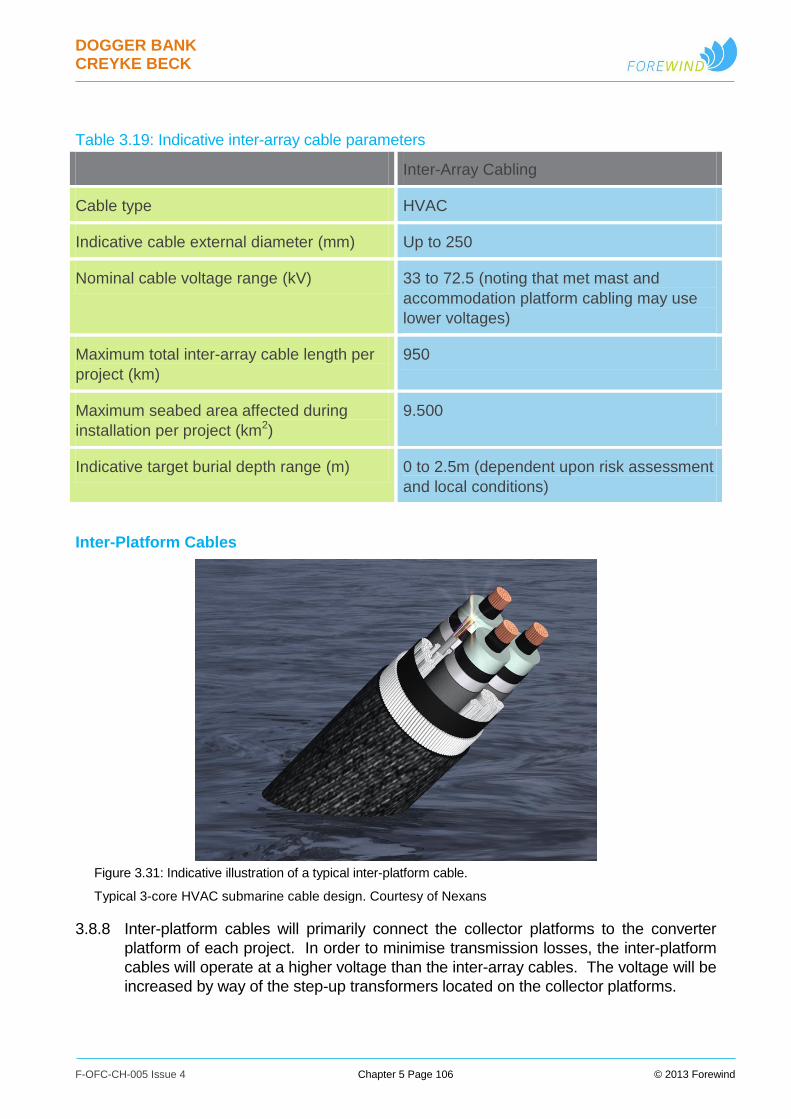
DOGGER BANK CREYKE BECK
F-OFC-CH-005 Issue 4 Chapter 5 Page 106 © 2013 Forewind
Table 3.19: Indicative inter-array cable parameters
Inter-Array Cabling
Cable type HVAC
Indicative cable external diameter (mm) Up to 250
Nominal cable voltage range (kV) 33 to 72.5 (noting that met mast and
accommodation platform cabling may use
lower voltages)
Maximum total inter-array cable length per
project (km)
950
Maximum seabed area affected during
installation per project (km2)
9.500
Indicative target burial depth range (m) 0 to 2.5m (dependent upon risk assessment
and local conditions)
Inter-Platform Cables
Figure 3.31: Indicative illustration of a typical inter-platform cable.
Typical 3-core HVAC submarine cable design. Courtesy of Nexans
3.8.8 Inter-platform cables will primarily connect the collector platforms to the converter
platform of each project. In order to minimise transmission losses, the inter-platform
cables will operate at a higher voltage than the inter-array cables. The voltage will be
increased by way of the step-up transformers located on the collector platforms.
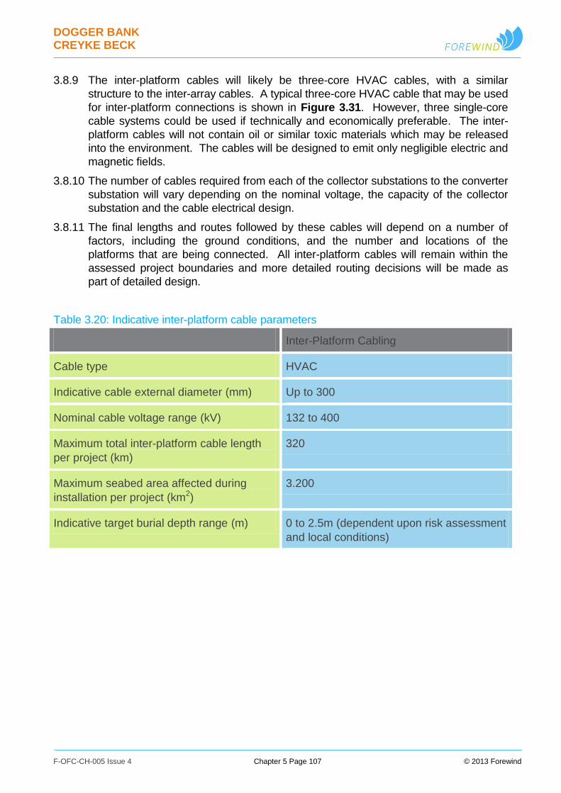
DOGGER BANK CREYKE BECK
F-OFC-CH-005 Issue 4 Chapter 5 Page 107 © 2013 Forewind
3.8.9 The inter-platform cables will likely be three-core HVAC cables, with a similar
structure to the inter-array cables. A typical three-core HVAC cable that may be used
for inter-platform connections is shown in Figure 3.31. However, three single-core
cable systems could be used if technically and economically preferable. The inter-
platform cables will not contain oil or similar toxic materials which may be released
into the environment. The cables will be designed to emit only negligible electric and
magnetic fields.
3.8.10 The number of cables required from each of the collector substations to the converter
substation will vary depending on the nominal voltage, the capacity of the collector
substation and the cable electrical design.
3.8.11 The final lengths and routes followed by these cables will depend on a number of
factors, including the ground conditions, and the number and locations of the
platforms that are being connected. All inter-platform cables will remain within the
assessed project boundaries and more detailed routing decisions will be made as
part of detailed design.
Table 3.20: Indicative inter-platform cable parameters
Inter-Platform Cabling
Cable type HVAC
Indicative cable external diameter (mm) Up to 300
Nominal cable voltage range (kV) 132 to 400
Maximum total inter-platform cable length
per project (km)
320
Maximum seabed area affected during
installation per project (km2)
3.200
Indicative target burial depth range (m) 0 to 2.5m (dependent upon risk assessment
and local conditions)
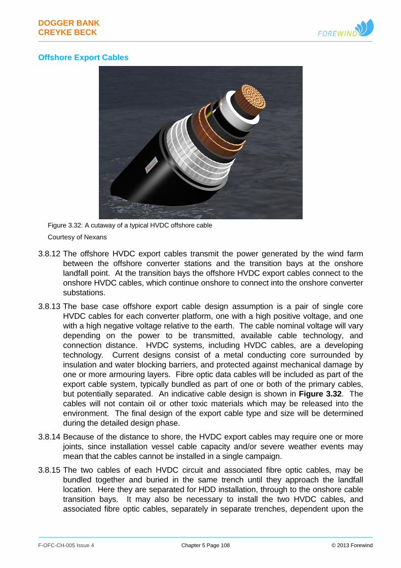
DOGGER BANK CREYKE BECK
F-OFC-CH-005 Issue 4 Chapter 5 Page 108 © 2013 Forewind
Offshore Export Cables
Figure 3.32: A cutaway of a typical HVDC offshore cable
Courtesy of Nexans
3.8.12 The offshore HVDC export cables transmit the power generated by the wind farm
between the offshore converter stations and the transition bays at the onshore
landfall point. At the transition bays the offshore HVDC export cables connect to the
onshore HVDC cables, which continue onshore to connect into the onshore converter
substations.
3.8.13 The base case offshore export cable design assumption is a pair of single core
HVDC cables for each converter platform, one with a high positive voltage, and one
with a high negative voltage relative to the earth. The cable nominal voltage will vary
depending on the power to be transmitted, available cable technology, and
connection distance. HVDC systems, including HVDC cables, are a developing
technology. Current designs consist of a metal conducting core surrounded by
insulation and water blocking barriers, and protected against mechanical damage by
one or more armouring layers. Fibre optic data cables will be included as part of the
export cable system, typically bundled as part of one or both of the primary cables,
but potentially separated. An indicative cable design is shown in Figure 3.32. The
cables will not contain oil or other toxic materials which may be released into the
environment. The final design of the export cable type and size will be determined
during the detailed design phase.
3.8.14 Because of the distance to shore, the HVDC export cables may require one or more
joints, since installation vessel cable capacity and/or severe weather events may
mean that the cables cannot be installed in a single campaign.
3.8.15 The two cables of each HVDC circuit and associated fibre optic cables, may be
bundled together and buried in the same trench until they approach the landfall
location. Here they are separated for HDD installation, through to the onshore cable
transition bays. It may also be necessary to install the two HVDC cables, and
associated fibre optic cables, separately in separate trenches, dependent upon the
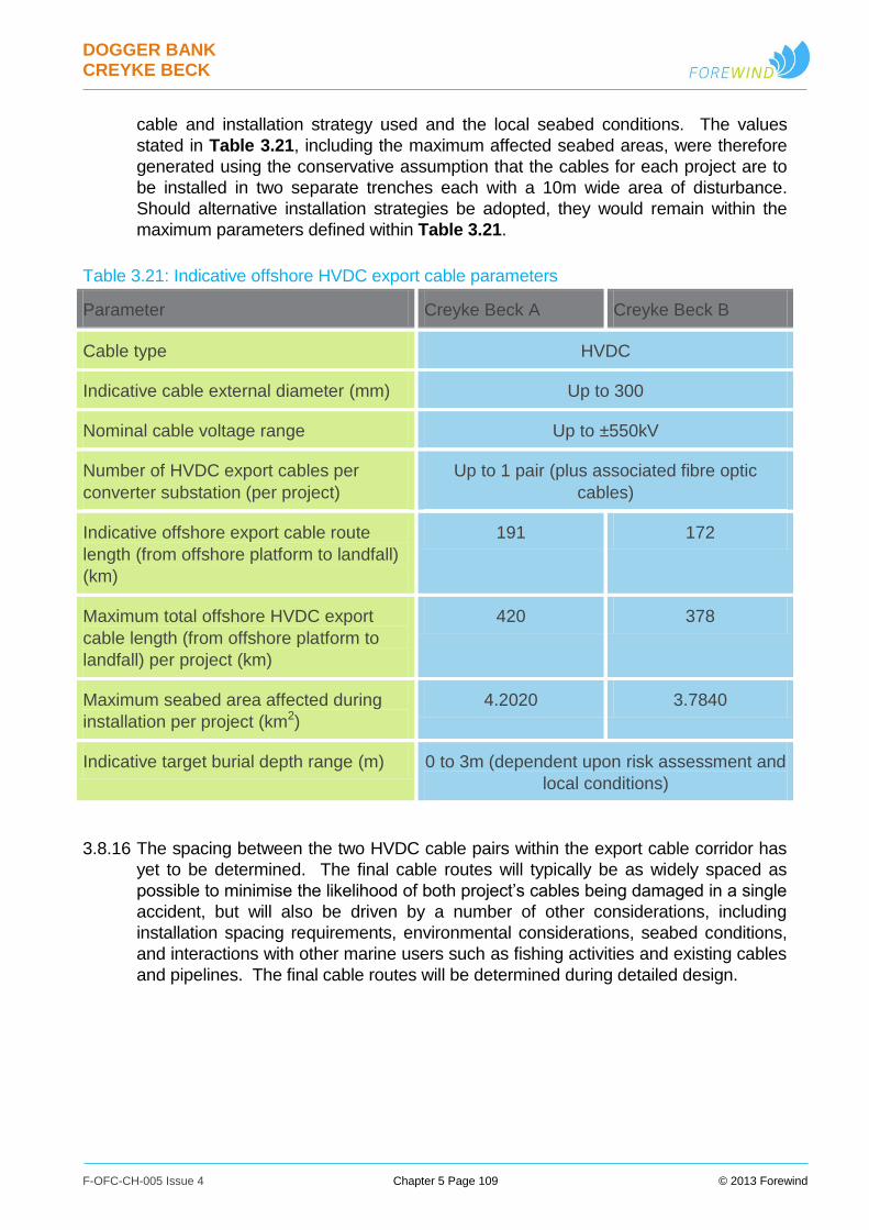
DOGGER BANK CREYKE BECK
F-OFC-CH-005 Issue 4 Chapter 5 Page 109 © 2013 Forewind
cable and installation strategy used and the local seabed conditions. The values
stated in Table 3.21, including the maximum affected seabed areas, were therefore
generated using the conservative assumption that the cables for each project are to
be installed in two separate trenches each with a 10m wide area of disturbance.
Should alternative installation strategies be adopted, they would remain within the
maximum parameters defined within Table 3.21.
Table 3.21: Indicative offshore HVDC export cable parameters
Parameter Creyke Beck A Creyke Beck B
Cable type HVDC
Indicative cable external diameter (mm) Up to 300
Nominal cable voltage range Up to ±550kV
Number of HVDC export cables per
converter substation (per project)
Up to 1 pair (plus associated fibre optic
cables)
Indicative offshore export cable route
length (from offshore platform to landfall)
(km)
191 172
Maximum total offshore HVDC export
cable length (from offshore platform to
landfall) per project (km)
420 378
Maximum seabed area affected during
installation per project (km2)
4.2020 3.7840
Indicative target burial depth range (m) 0 to 3m (dependent upon risk assessment and
local conditions)
3.8.16 The spacing between the two HVDC cable pairs within the export cable corridor has
yet to be determined. The final cable routes will typically be as widely spaced as
possible to minimise the likelihood of both project’s cables being damaged in a single
accident, but will also be driven by a number of other considerations, including
installation spacing requirements, environmental considerations, seabed conditions,
and interactions with other marine users such as fishing activities and existing cables
and pipelines. The final cable routes will be determined during detailed design.
DOGGER BANK CREYKE BECK
F-OFC-CH-005 Issue 4 Chapter 5 Page 110 © 2013 Forewind
3.9 Offshore Cable Installation and Removal
Offshore Cable Installation
3.9.1 The typical key stages of offshore cable installation have been defined as:
Pre-installation survey;
Route clearance;
Cable lay and burial;
Remedial cable protection (if required);
Cable and pipeline crossings (if required);
Post-installation survey.
3.9.2 Details of the activities undertaken during these stages are provided below.
Pre-Installation Surveys
3.9.3 A pre-installation geophysical and/or geotechnical route survey will be conducted
approximately 3-6 months prior to the marine installation works. In addition,
immediately prior to the installation a visual inspection and confirmation of the route
may be carried out using an ROV.
Route Clearance
3.9.4 Prior to the installation of a submarine cable, the precise route along which the cable
burial is planned may be cleared of decommissioned cables and any seabed debris
that may delay or endanger the progress of burial operations. This should ensure
that the selected route is free from seabed and sub-surface debris or any artificial
hazards.
3.9.5 Various route clearance techniques may be employed, depending on the nature of
any obstacles identified. One standard option is a pre-lay grapnel run. This consists
of a grapnel (hooked) device being towed along the precise line of the cable
installation to sweep the route clear of obstacles. Alternative techniques include the
use of boulder ploughs (devices similar to snowploughs) in a similar manner, and
preparing areas with seabed conditions such as sand waves by using suitable
equipment, such as sweeps or dredgers, to smooth the identified route.
3.9.6 For specific known issues, alternative approaches exist depending on the nature of
the obstacles: potentially including the use of ROVs or grabs to cut and/or remove
obstacles at the seabed. This could for instance include the removal of problematic
boulders or debris identified along a route. In the case of out-of-service cables, these
may be able to be removed or cut as opposed to requiring a full cable crossing, as
discussed later within this section.
Cable Lay and Burial
3.9.7 Offshore cables are typically installed from a cable laying vessel, Figure 3.33, or
barge, Figure 3.34 and Figure 3.35, using either a multi-point anchoring or dynamic
positioning system. The cable installation vessels will be equipped with specialist

DOGGER BANK CREYKE BECK
F-OFC-CH-005 Issue 4 Chapter 5 Page 111 © 2013 Forewind
cable handling equipment and will have support vessels in attendance as necessary.
The cables will be stored on carousels or drums mounted on the deck of the vessels,
and the cables then deployed onto the seabed using the cable handling equipment.
3.9.8 Cable lay and burial alternatives include one or a combination of the following:
Direct burial during the laying campaign (cables laid and buried as part of a
single activity);
Pre-trenching (trenches created separately in advance, cables then
subsequently laid into the trenches as a separate activity), and;
Post-lay burial (cables laid separately in advance, cables then subsequently
buried as a separate activity).
3.9.9 The two latter options have the advantage that the cable lay can be completed more
rapidly with the slower task of cable trenching being performed independently. A
typical cable installation methodology, based upon direct burial during the burial
campaign, is summarised as follows:
i. The cable laying vessel approaches the first structure and the cable end is floated
off from the vessel to the structure;
ii. The cable is carefully pulled through the J-tube on the structure via a line on the
cable end, fed through the J-tube and back to a winch on the vessel;
iii. The cable in the vicinity of the J-tube may be protected, for example by high density
polyethylene (HDPE) half-shell castings or equivalent protective measures installed
onto the cable, during deployment from the vessel;
iv. When the cable reaches the cable termination point, the pulling operation ceases
and the end of the cable is terminated into an electrical equipment enclosure;
v. On the cable laying vessel, the cable is loaded through the plough or trenching unit,
which is then deployed onto the seabed. This allows simultaneous lay and burial of
the cable along its route;
vi. For cables which terminate at an offshore structure, as the vessel approaches the
end structure the cable burial equipment is recovered onto the vessel; and
vii. The end of the cable is then passed off the vessel and floated towards the endpoint
structure. Connection to the second structure is completed through the J-tube, as
described above.
3.9.10 In the case of pre-trenching a cable trench would be created shortly before cable lay,
and then either filled during the cable lay process, or allowed to re-fill naturally. In the
case of post-lay burial, cables are temporarily laid onto the seabed surface, either
waiting alternative protection or post-lay burial. In these cases the cables are simply
laid without the use of a burial plough or trenching unit, as described in point (v) in
the methodology above, but by controlling the position and speed of the installation
vessel and the speed of the carousel.
3.9.11 Depending on the cable type it may be possible to lay the majority of cables as single
lengths without cable joints being necessary. However, this may not be possible in
all cases. Because of the distance to shore the HVDC export cables may, for
example, require one or more joints.
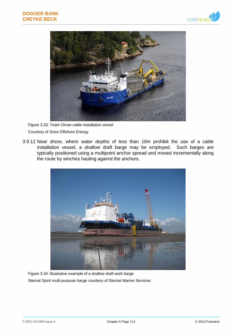
DOGGER BANK CREYKE BECK
F-OFC-CH-005 Issue 4 Chapter 5 Page 112 © 2013 Forewind
Figure 3.33: Team Oman cable installation vessel
Courtesy of Scira Offshore Energy
3.9.12 Near shore, where water depths of less than 10m prohibit the use of a cable
installation vessel, a shallow draft barge may be employed. Such barges are
typically positioned using a multipoint anchor spread and moved incrementally along
the route by winches hauling against the anchors.
Figure 3.34: Illustrative example of a shallow draft work barge
Stemat Spirit multi-purpose barge courtesy of Stemat Marine Services
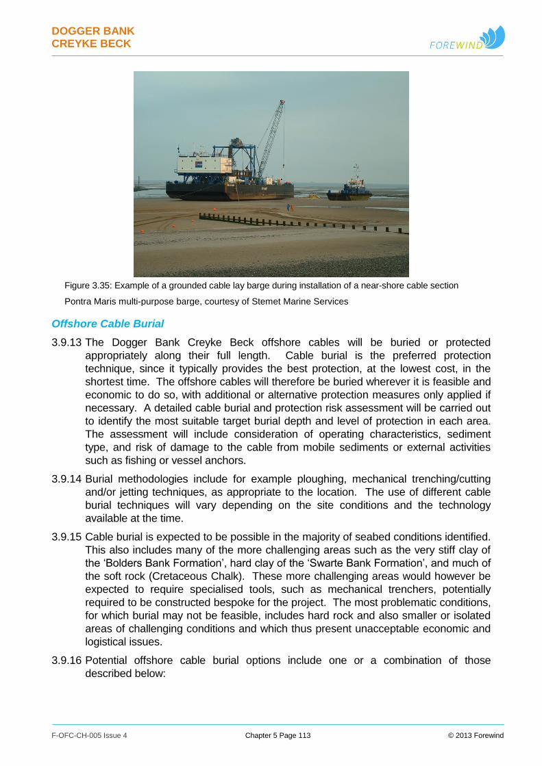
DOGGER BANK CREYKE BECK
F-OFC-CH-005 Issue 4 Chapter 5 Page 113 © 2013 Forewind
Figure 3.35: Example of a grounded cable lay barge during installation of a near-shore cable section
Pontra Maris multi-purpose barge, courtesy of Stemet Marine Services
Offshore Cable Burial
3.9.13 The Dogger Bank Creyke Beck offshore cables will be buried or protected
appropriately along their full length. Cable burial is the preferred protection
technique, since it typically provides the best protection, at the lowest cost, in the
shortest time. The offshore cables will therefore be buried wherever it is feasible and
economic to do so, with additional or alternative protection measures only applied if
necessary. A detailed cable burial and protection risk assessment will be carried out
to identify the most suitable target burial depth and level of protection in each area.
The assessment will include consideration of operating characteristics, sediment
type, and risk of damage to the cable from mobile sediments or external activities
such as fishing or vessel anchors.
3.9.14 Burial methodologies include for example ploughing, mechanical trenching/cutting
and/or jetting techniques, as appropriate to the location. The use of different cable
burial techniques will vary depending on the site conditions and the technology
available at the time.
3.9.15 Cable burial is expected to be possible in the majority of seabed conditions identified.
This also includes many of the more challenging areas such as the very stiff clay of
the ‘Bolders Bank Formation’, hard clay of the ‘Swarte Bank Formation’, and much of
the soft rock (Cretaceous Chalk). These more challenging areas would however be
expected to require specialised tools, such as mechanical trenchers, potentially
required to be constructed bespoke for the project. The most problematic conditions,
for which burial may not be feasible, includes hard rock and also smaller or isolated
areas of challenging conditions and which thus present unacceptable economic and
logistical issues.
3.9.16 Potential offshore cable burial options include one or a combination of those
described below:
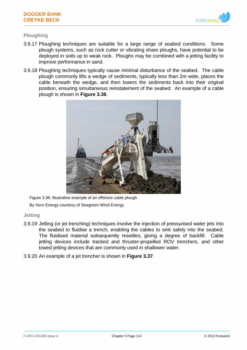
DOGGER BANK CREYKE BECK
F-OFC-CH-005 Issue 4 Chapter 5 Page 114 © 2013 Forewind
Ploughing
3.9.17 Ploughing techniques are suitable for a large range of seabed conditions. Some
plough systems, such as rock cutter or vibrating share ploughs, have potential to be
deployed in soils up to weak rock. Ploughs may be combined with a jetting facility to
improve performance in sand.
3.9.18 Ploughing techniques typically cause minimal disturbance of the seabed. The cable
plough commonly lifts a wedge of sediments, typically less than 2m wide, places the
cable beneath the wedge, and then lowers the sediments back into their original
position, ensuring simultaneous reinstatement of the seabed. An example of a cable
plough is shown in Figure 3.36.
Figure 3.36: Illustrative example of an offshore cable plough
By Xero Energy courtesy of Seagreen Wind Energy
Jetting
3.9.19 Jetting (or jet trenching) techniques involve the injection of pressurised water jets into
the seabed to fluidise a trench, enabling the cables to sink safely into the seabed.
The fluidised material subsequently resettles, giving a degree of backfill. Cable
jetting devices include tracked and thruster-propelled ROV trenchers, and other
towed jetting devices that are commonly used in shallower water.
3.9.20 An example of a jet trencher is shown in Figure 3.37.
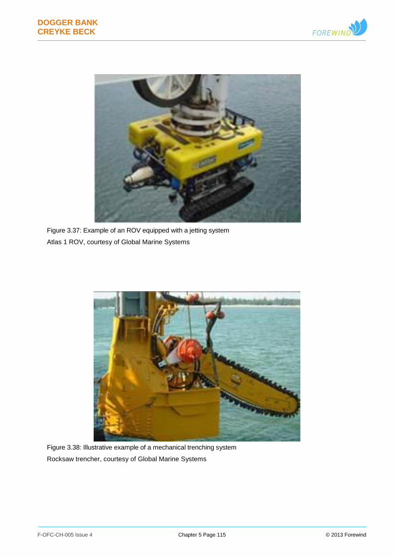
DOGGER BANK CREYKE BECK
F-OFC-CH-005 Issue 4 Chapter 5 Page 115 © 2013 Forewind
Figure 3.37: Example of an ROV equipped with a jetting system
Atlas 1 ROV, courtesy of Global Marine Systems
Figure 3.38: Illustrative example of a mechanical trenching system
Rocksaw trencher, courtesy of Global Marine Systems
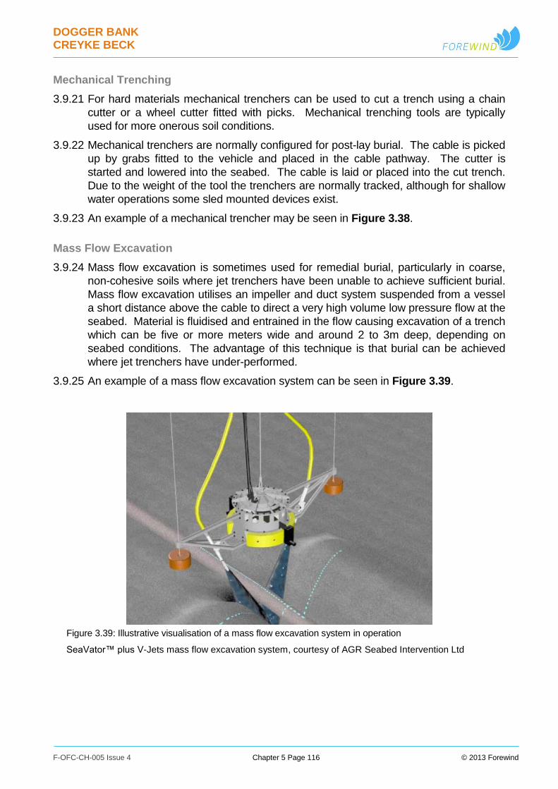
DOGGER BANK CREYKE BECK
F-OFC-CH-005 Issue 4 Chapter 5 Page 116 © 2013 Forewind
Mechanical Trenching
3.9.21 For hard materials mechanical trenchers can be used to cut a trench using a chain
cutter or a wheel cutter fitted with picks. Mechanical trenching tools are typically
used for more onerous soil conditions.
3.9.22 Mechanical trenchers are normally configured for post-lay burial. The cable is picked
up by grabs fitted to the vehicle and placed in the cable pathway. The cutter is
started and lowered into the seabed. The cable is laid or placed into the cut trench.
Due to the weight of the tool the trenchers are normally tracked, although for shallow
water operations some sled mounted devices exist.
3.9.23 An example of a mechanical trencher may be seen in Figure 3.38.
Mass Flow Excavation
3.9.24 Mass flow excavation is sometimes used for remedial burial, particularly in coarse,
non-cohesive soils where jet trenchers have been unable to achieve sufficient burial.
Mass flow excavation utilises an impeller and duct system suspended from a vessel
a short distance above the cable to direct a very high volume low pressure flow at the
seabed. Material is fluidised and entrained in the flow causing excavation of a trench
which can be five or more meters wide and around 2 to 3m deep, depending on
seabed conditions. The advantage of this technique is that burial can be achieved
where jet trenchers have under-performed.
3.9.25 An example of a mass flow excavation system can be seen in Figure 3.39.
Figure 3.39: Illustrative visualisation of a mass flow excavation system in operation
SeaVator™ plus V-Jets mass flow excavation system, courtesy of AGR Seabed Intervention Ltd

DOGGER BANK CREYKE BECK
F-OFC-CH-005 Issue 4 Chapter 5 Page 117 © 2013 Forewind
Post-Installation Surveys
3.9.26 A post-installation route survey will be conducted after the completion of the cable
installation works. This will confirm the as-built condition of the cabling and the actual
levels of burial achieved and potentially identify any needs for remedial cable
protection.
Removal of Offshore Cables
3.9.27 During the construction of the project there may be a requirement to remove or
relocate portions of existing cables in proximity to the project wind turbine array areas
or export cable routes. Examples may include works taking place in the vicinity of
decommissioned telecommunication cables. Although in these circumstances
existing cables will generally be left in-situ, in some cases removal may be judged to
be preferable.
3.9.28 A typical methodology used for the removal of cables may include:
i. Use of grapnels, and/or ROVs (potentially including jetting systems to uncover
buried sections) to find, physically contact and retrieve cables;
ii. The required section of cable is cut, pulled out of the seabed, and retrieved onto a
vessel for disposal onshore as appropriate;
iii. Any remaining cut ends of cable will be weighted as required and returned to the
seabed;
iv. This could potentially be followed by re-installation, in a new location if required,
using techniques as described in the cable installation section; and
v. Admiralty charts will be updated to reflect the new situation.
3.9.29 As discussed in Section 5.5 Proximity to Existing Infrastructure, the necessary
agreements would always be sought from the cable owners. The lifting and re-laying
of cables may be subject to additional consents, and the necessary permissions
would be sought should this be required.
3.9.30 For the purposes of assessment, the environmental impact of cable removal will be
considered to be equivalent to cable installation. This is judged to be a conservative
assumption as the installation methodologies within the development envelope,
including jetting, ploughing and cutting tools, are judged to generate greater footprint
impacts and sediment volumes than the potential methods of cable removal. This
assumption is also in line with the common assumption that the impact of
decommissioning is equivalent to construction.
3.9.31 The total length of cables both installed and removed will therefore be required to fall
within our total development envelope limit for installed length of cable, as described
within Section 3.8 Offshore Cables. Therefore, for example, if 2km of cables were
removed, then the maximum length of cables which could be installed should be
reduced by a corresponding 2km.
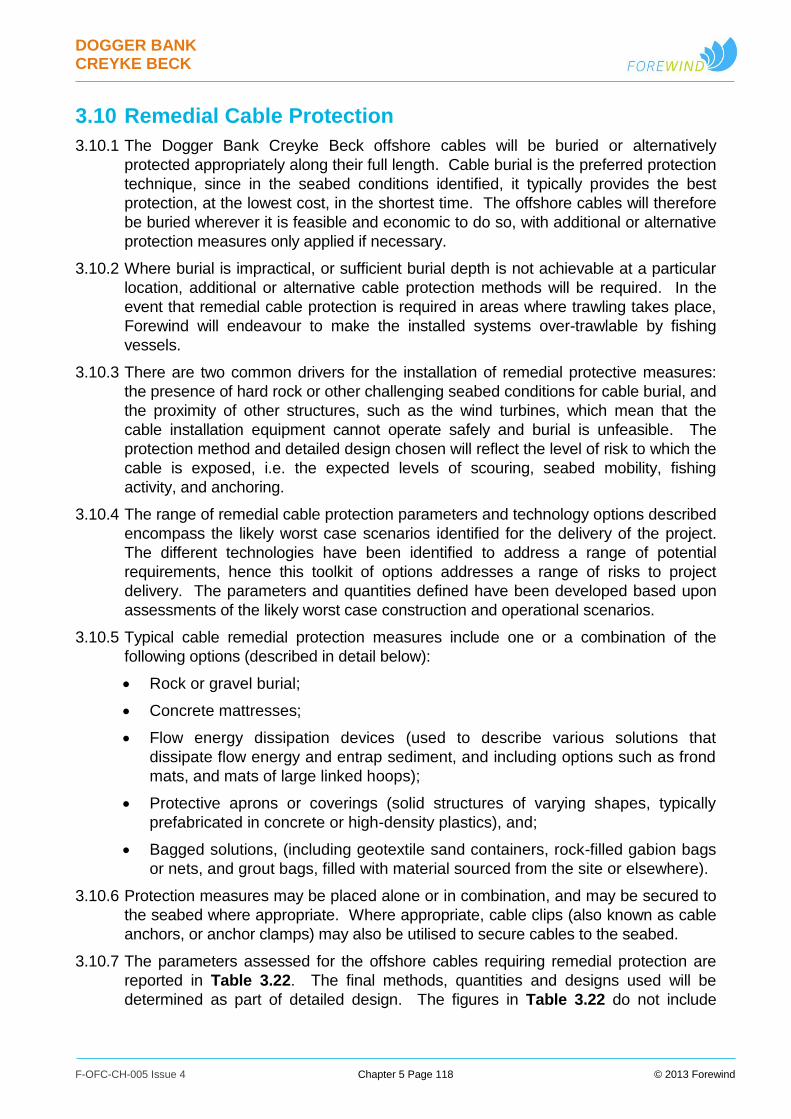
DOGGER BANK CREYKE BECK
F-OFC-CH-005 Issue 4 Chapter 5 Page 118 © 2013 Forewind
3.10 Remedial Cable Protection
3.10.1 The Dogger Bank Creyke Beck offshore cables will be buried or alternatively
protected appropriately along their full length. Cable burial is the preferred protection
technique, since in the seabed conditions identified, it typically provides the best
protection, at the lowest cost, in the shortest time. The offshore cables will therefore
be buried wherever it is feasible and economic to do so, with additional or alternative
protection measures only applied if necessary.
3.10.2 Where burial is impractical, or sufficient burial depth is not achievable at a particular
location, additional or alternative cable protection methods will be required. In the
event that remedial cable protection is required in areas where trawling takes place,
Forewind will endeavour to make the installed systems over-trawlable by fishing
vessels.
3.10.3 There are two common drivers for the installation of remedial protective measures:
the presence of hard rock or other challenging seabed conditions for cable burial, and
the proximity of other structures, such as the wind turbines, which mean that the
cable installation equipment cannot operate safely and burial is unfeasible. The
protection method and detailed design chosen will reflect the level of risk to which the
cable is exposed, i.e. the expected levels of scouring, seabed mobility, fishing
activity, and anchoring.
3.10.4 The range of remedial cable protection parameters and technology options described
encompass the likely worst case scenarios identified for the delivery of the project.
The different technologies have been identified to address a range of potential
requirements, hence this toolkit of options addresses a range of risks to project
delivery. The parameters and quantities defined have been developed based upon
assessments of the likely worst case construction and operational scenarios.
3.10.5 Typical cable remedial protection measures include one or a combination of the
following options (described in detail below):
Rock or gravel burial;
Concrete mattresses;
Flow energy dissipation devices (used to describe various solutions that
dissipate flow energy and entrap sediment, and including options such as frond
mats, and mats of large linked hoops);
Protective aprons or coverings (solid structures of varying shapes, typically
prefabricated in concrete or high-density plastics), and;
Bagged solutions, (including geotextile sand containers, rock-filled gabion bags
or nets, and grout bags, filled with material sourced from the site or elsewhere).
3.10.6 Protection measures may be placed alone or in combination, and may be secured to
the seabed where appropriate. Where appropriate, cable clips (also known as cable
anchors, or anchor clamps) may also be utilised to secure cables to the seabed.
3.10.7 The parameters assessed for the offshore cables requiring remedial protection are
reported in Table 3.22. The final methods, quantities and designs used will be
determined as part of detailed design. The figures in Table 3.22 do not include
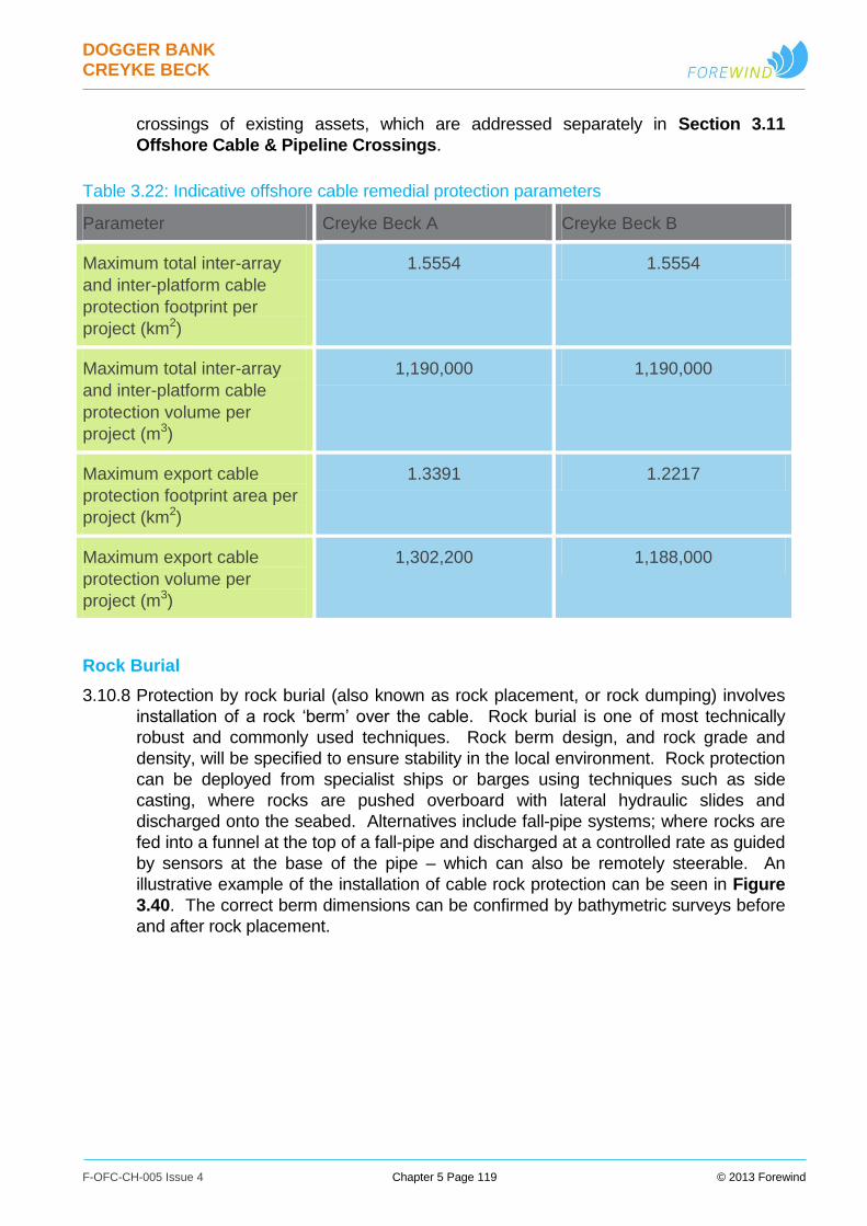
DOGGER BANK CREYKE BECK
F-OFC-CH-005 Issue 4 Chapter 5 Page 119 © 2013 Forewind
crossings of existing assets, which are addressed separately in Section 3.11
Offshore Cable & Pipeline Crossings.
Table 3.22: Indicative offshore cable remedial protection parameters
Parameter Creyke Beck A Creyke Beck B
Maximum total inter-array
and inter-platform cable
protection footprint per
project (km2)
1.5554 1.5554
Maximum total inter-array
and inter-platform cable
protection volume per
project (m3)
1,190,000 1,190,000
Maximum export cable
protection footprint area per
project (km2)
1.3391 1.2217
Maximum export cable
protection volume per
project (m3)
1,302,200 1,188,000
Rock Burial
3.10.8 Protection by rock burial (also known as rock placement, or rock dumping) involves
installation of a rock ‘berm’ over the cable. Rock burial is one of most technically
robust and commonly used techniques. Rock berm design, and rock grade and
density, will be specified to ensure stability in the local environment. Rock protection
can be deployed from specialist ships or barges using techniques such as side
casting, where rocks are pushed overboard with lateral hydraulic slides and
discharged onto the seabed. Alternatives include fall-pipe systems; where rocks are
fed into a funnel at the top of a fall-pipe and discharged at a controlled rate as guided
by sensors at the base of the pipe – which can also be remotely steerable. An
illustrative example of the installation of cable rock protection can be seen in Figure
3.40. The correct berm dimensions can be confirmed by bathymetric surveys before
and after rock placement.
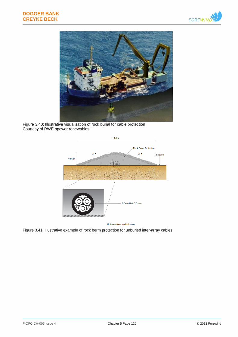
DOGGER BANK CREYKE BECK
F-OFC-CH-005 Issue 4 Chapter 5 Page 120 © 2013 Forewind
Figure 3.40: Illustrative visualisation of rock burial for cable protection Courtesy of RWE npower renewables
Figure 3.41: Illustrative example of rock berm protection for unburied inter-array cables

DOGGER BANK CREYKE BECK
F-OFC-CH-005 Issue 4 Chapter 5 Page 121 © 2013 Forewind
Figure 3.42: Illustrative example of rock berm protection for unburied export cables
Concrete Mattresses
3.10.9 Concrete mattresses consist of a number of concrete blocks linked together by
flexible cables. There are various designs of concrete mattresses available. The
most suited concrete mattress will depend on a number of factors including
application, function and environmental conditions. Designs include options with
smoothly tapered edge sections intended to have reduced impact upon trawling, and
mattresses with integrated frond mats (described below). Some local factors, such
as heavy trawling activity, may however make mattressing inappropriate. For
installation, the concrete mattresses are lowered down by crane over the cables in a
pre-determined pattern to hold the cables in place and provide protection against
fishing gear and vessel anchors. An illustrative example of a concrete mattress is
shown in Figure 3.43.
Figure 3.43: Illustrative example of concrete mattress cable protection
Pipeshield Bi-Flex Concrete Mattress. Courtesy of Pipeshield
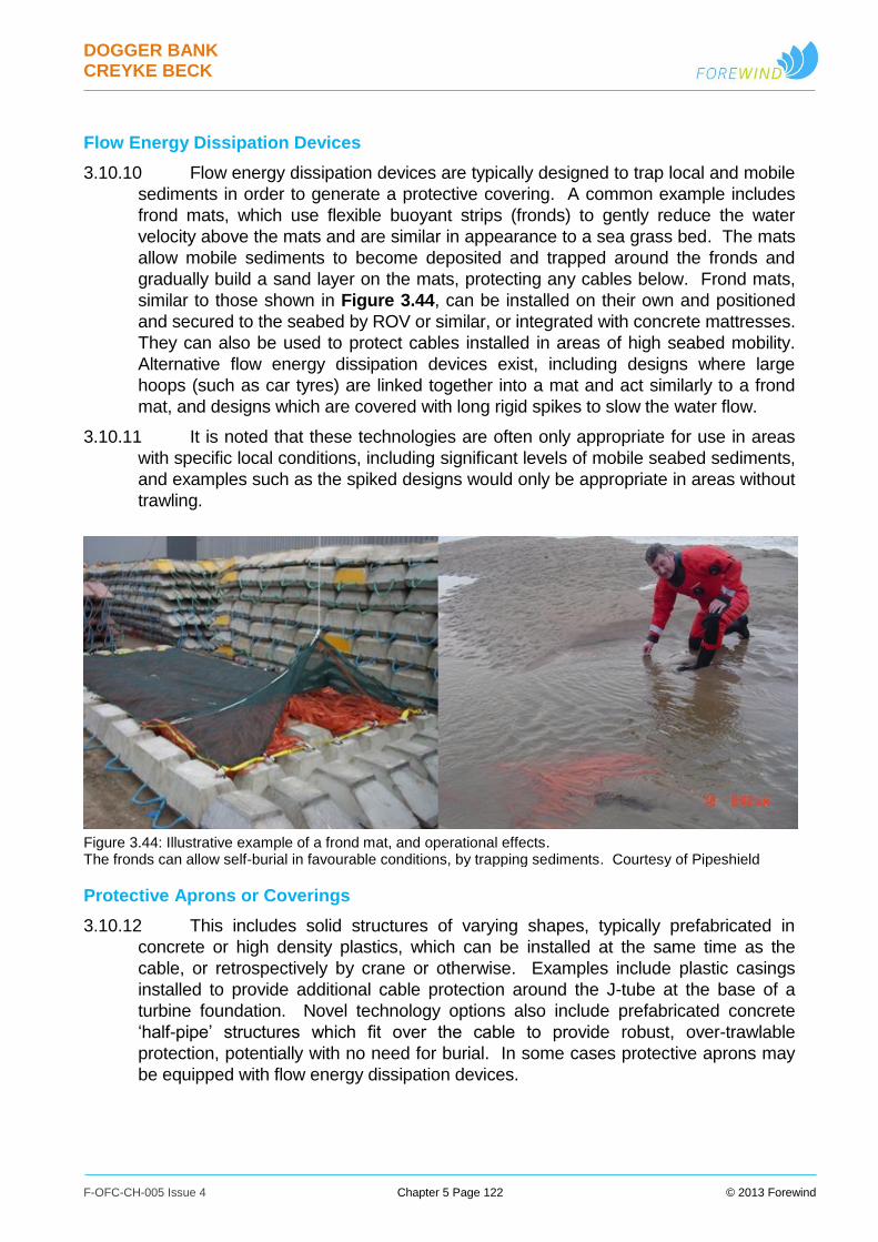
DOGGER BANK CREYKE BECK
F-OFC-CH-005 Issue 4 Chapter 5 Page 122 © 2013 Forewind
Flow Energy Dissipation Devices
3.10.10 Flow energy dissipation devices are typically designed to trap local and mobile
sediments in order to generate a protective covering. A common example includes
frond mats, which use flexible buoyant strips (fronds) to gently reduce the water
velocity above the mats and are similar in appearance to a sea grass bed. The mats
allow mobile sediments to become deposited and trapped around the fronds and
gradually build a sand layer on the mats, protecting any cables below. Frond mats,
similar to those shown in Figure 3.44, can be installed on their own and positioned
and secured to the seabed by ROV or similar, or integrated with concrete mattresses.
They can also be used to protect cables installed in areas of high seabed mobility.
Alternative flow energy dissipation devices exist, including designs where large
hoops (such as car tyres) are linked together into a mat and act similarly to a frond
mat, and designs which are covered with long rigid spikes to slow the water flow.
3.10.11 It is noted that these technologies are often only appropriate for use in areas
with specific local conditions, including significant levels of mobile seabed sediments,
and examples such as the spiked designs would only be appropriate in areas without
trawling.
Figure 3.44: Illustrative example of a frond mat, and operational effects. The fronds can allow self-burial in favourable conditions, by trapping sediments. Courtesy of Pipeshield
Protective Aprons or Coverings
3.10.12 This includes solid structures of varying shapes, typically prefabricated in
concrete or high density plastics, which can be installed at the same time as the
cable, or retrospectively by crane or otherwise. Examples include plastic casings
installed to provide additional cable protection around the J-tube at the base of a
turbine foundation. Novel technology options also include prefabricated concrete
‘half-pipe’ structures which fit over the cable to provide robust, over-trawlable
protection, potentially with no need for burial. In some cases protective aprons may
be equipped with flow energy dissipation devices.

DOGGER BANK CREYKE BECK
F-OFC-CH-005 Issue 4 Chapter 5 Page 123 © 2013 Forewind
Figure 3.45: Illustrative example of cable protective covering
Courtesy of SeaCult (patented concept)
Bagged Solutions
3.10.13 These include geotextile sand containers, rock-filled gabion bags or nets, and
grout bags. Bags are typically lowered into position by crane from a surface vessel,
individually or in groups. These options are often used in proximity to a foundation
base and around J-tubes, since precise placement is possible.
3.10.14 Examples of gabion bags and grout bags can be seen in Figure 3.46 and
Figure 3.47 respectively.
Figure 3.46: Illustrative example of a rock-filled bag for cable protection
Subsea rated 1Te bulk-bags. Courtesy of Pipeshield
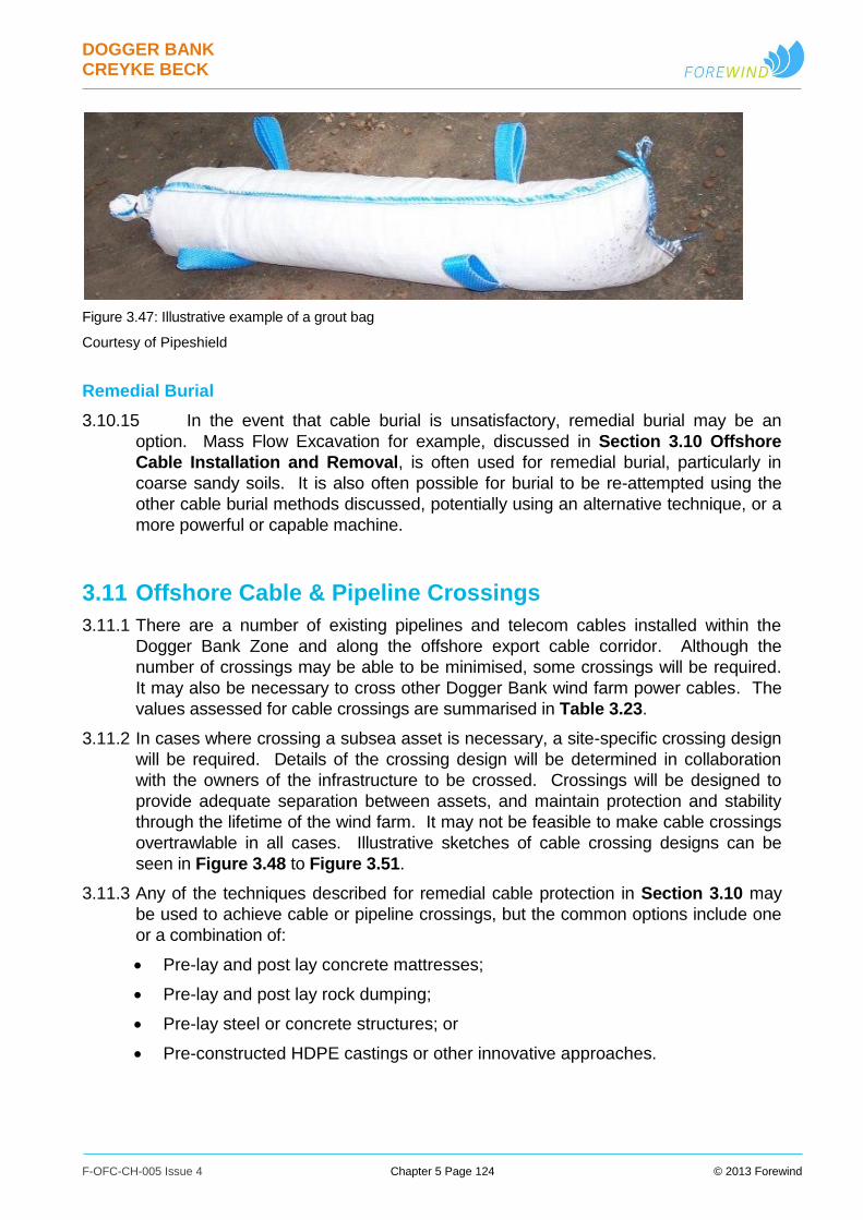
DOGGER BANK CREYKE BECK
F-OFC-CH-005 Issue 4 Chapter 5 Page 124 © 2013 Forewind
Figure 3.47: Illustrative example of a grout bag
Courtesy of Pipeshield
Remedial Burial
3.10.15 In the event that cable burial is unsatisfactory, remedial burial may be an
option. Mass Flow Excavation for example, discussed in Section 3.10 Offshore
Cable Installation and Removal, is often used for remedial burial, particularly in
coarse sandy soils. It is also often possible for burial to be re-attempted using the
other cable burial methods discussed, potentially using an alternative technique, or a
more powerful or capable machine.
3.11 Offshore Cable & Pipeline Crossings
3.11.1 There are a number of existing pipelines and telecom cables installed within the
Dogger Bank Zone and along the offshore export cable corridor. Although the
number of crossings may be able to be minimised, some crossings will be required.
It may also be necessary to cross other Dogger Bank wind farm power cables. The
values assessed for cable crossings are summarised in Table 3.23.
3.11.2 In cases where crossing a subsea asset is necessary, a site-specific crossing design
will be required. Details of the crossing design will be determined in collaboration
with the owners of the infrastructure to be crossed. Crossings will be designed to
provide adequate separation between assets, and maintain protection and stability
through the lifetime of the wind farm. It may not be feasible to make cable crossings
overtrawlable in all cases. Illustrative sketches of cable crossing designs can be
seen in Figure 3.48 to Figure 3.51.
3.11.3 Any of the techniques described for remedial cable protection in Section 3.10 may
be used to achieve cable or pipeline crossings, but the common options include one
or a combination of:
Pre-lay and post lay concrete mattresses;
Pre-lay and post lay rock dumping;
Pre-lay steel or concrete structures; or
Pre-constructed HDPE castings or other innovative approaches.

DOGGER BANK CREYKE BECK
F-OFC-CH-005 Issue 4 Chapter 5 Page 125 © 2013 Forewind
3.11.4 The installation techniques described in the cable protection section can be similarly
applied in the context of cable and pipeline crossings. A typical sequence for an
installation based on concrete mattresses would be as follows:
i. The proposed crossing locations are surveyed to confirm the precise location and
burial depth of the existing assets, and the crossing designed accordingly;
ii. An installation vessel places concrete mattresses perpendicular to the orientation of
the existing asset;
iii. The cable installation vessel lays the cables over the mattresses. Burial would
terminate a short distance from the existing asset, and the cables may have HDPE
half-shell castings installed onto the cable as they are deployed from the laying
vessel for additional protection in the region of the crossing;
iv. The mattress installation vessel places additional concrete mattresses, aligned with
the orientation of the newly installed cable, for top protection;
v. Rock burial is carried out on the mattress edges, to stabilise them.
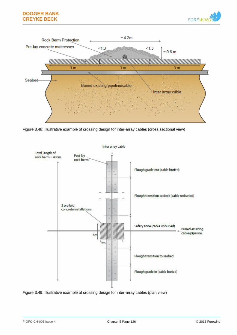
DOGGER BANK CREYKE BECK
F-OFC-CH-005 Issue 4 Chapter 5 Page 126 © 2013 Forewind
Figure 3.48: Illustrative example of crossing design for inter-array cables (cross sectional view)
Figure 3.49: Illustrative example of crossing design for inter-array cables (plan view)
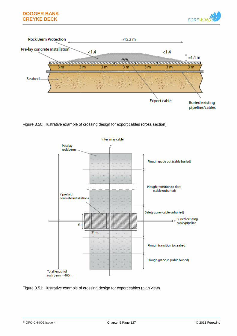
DOGGER BANK CREYKE BECK
F-OFC-CH-005 Issue 4 Chapter 5 Page 127 © 2013 Forewind
Figure 3.50: Illustrative example of crossing design for export cables (cross section)
Figure 3.51: Illustrative example of crossing design for export cables (plan view)

DOGGER BANK CREYKE BECK
F-OFC-CH-005 Issue 4 Chapter 5 Page 128 © 2013 Forewind
Table 3.23: Indicative crossing protection parameters
Parameter Project A Project B
Inter-Array and Inter-platform Cables
Maximum number of inter-array
and inter-platform cable crossings
(including crossings of both third
party and other Dogger Bank
assets)
17 0
Maximum volume of inter-array
and inter-platform cable crossing
material per project (m3)
20,000 0
Maximum total footprint of inter-
array and inter-platform cable
crossings per project (km2)
0.0380 0
Export Cables
Maximum number of export cable
crossings (including crossings of
both third party and other Dogger
Bank assets)
10 20
Maximum total volume of export
cable crossings protection
material per project (m3)
59,600 119,300
Maximum total footprint of export
cable crossing protection material
per project (km2)
0.0613 0.1226
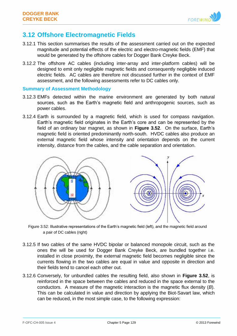
DOGGER BANK CREYKE BECK
F-OFC-CH-005 Issue 4 Chapter 5 Page 129 © 2013 Forewind
3.12 Offshore Electromagnetic Fields
3.12.1 This section summarises the results of the assessment carried out on the expected
magnitude and potential effects of the electric and electro-magnetic fields (EMF) that
would be generated by the offshore cables for Dogger Bank Creyke Beck.
3.12.2 The offshore AC cables (including inter-array and inter-platform cables) will be
designed to emit only negligible magnetic fields and consequently negligible induced
electric fields. AC cables are therefore not discussed further in the context of EMF
assessment, and the following assessments refer to DC cables only.
Summary of Assessment Methodology
3.12.3 EMFs detected within the marine environment are generated by both natural
sources, such as the Earth’s magnetic field and anthropogenic sources, such as
power cables.
3.12.4 Earth is surrounded by a magnetic field, which is used for compass navigation.
Earth’s magnetic field originates in the Earth’s core and can be represented by the
field of an ordinary bar magnet, as shown in Figure 3.52. On the surface, Earth’s
magnetic field is oriented predominantly north-south. HVDC cables also produce an
external magnetic field whose intensity and orientation depends on the current
intensity, distance from the cables, and the cable separation and orientation.
Figure 3.52: Illustrative representations of the Earth’s magnetic field (left), and the magnetic field around
a pair of DC cables (right)
3.12.5 If two cables of the same HVDC bipolar or balanced monopole circuit, such as the
ones the will be used for Dogger Bank Creyke Beck, are bundled together i.e.
installed in close proximity, the external magnetic field becomes negligible since the
currents flowing in the two cables are equal in value and opposite in direction and
their fields tend to cancel each other out.
3.12.6 Conversely, for unbundled cables the resulting field, also shown in Figure 3.52, is
reinforced in the space between the cables and reduced in the space external to the
conductors. A measure of the magnetic interaction is the magnetic flux density (B).
This can be calculated in value and direction by applying the Biot-Savart law, which
can be reduced, in the most simple case, to the following expression:
DOGGER BANK CREYKE BECK
F-OFC-CH-005 Issue 4 Chapter 5 Page 130 © 2013 Forewind
Where I is the current, µ the magnetic permeability of the medium, and R is the radial
distance from the current (cable) axis.
3.12.7 The magnetic field produced by cables sums up geometrically with Earth’s magnetic
field, resulting in a modified overall magnetic field, causing compass deviation. The
compass deviation caused by a pair of HVDC cables in a bipolar system can
therefore be assessed by applying the equations above and superposing the effects
of the two cables.
Offshore EMF Assessment Results (DC Cables Only)
3.12.8 The compass deviation potentially generated by a pair of Dogger Bank Creyke Beck
cables therefore varies with several key variables, including:
Orientation – the interaction with the Earth’s magnetic field means that
orientation has a substantial influence, (for example cables laid east-west
should not affect compass navigation);
Cable spacing – the spacing of the two cables will influence the magnitude,
extent and shape of the affected areas. In particular, the area affected will
reduce as cable spacing is reduced, and bundled cables will have no expected
affect at all upon compasses;
Electric current – the magnetic field strength varies with the square of the
current, so during periods when the wind farm is operating below maximum
output, the effect upon compasses may be substantially reduced;
Proximity to cables – the effects upon magnetic compasses are highly localised,
and even in severe cases typically drop to negligible levels within a few tens of
metres.
3.12.9 Table 3.24 shows compass deviation values for a set of example cases. These
assume a conservative cable orientation, and the maximum peak current through the
cables.
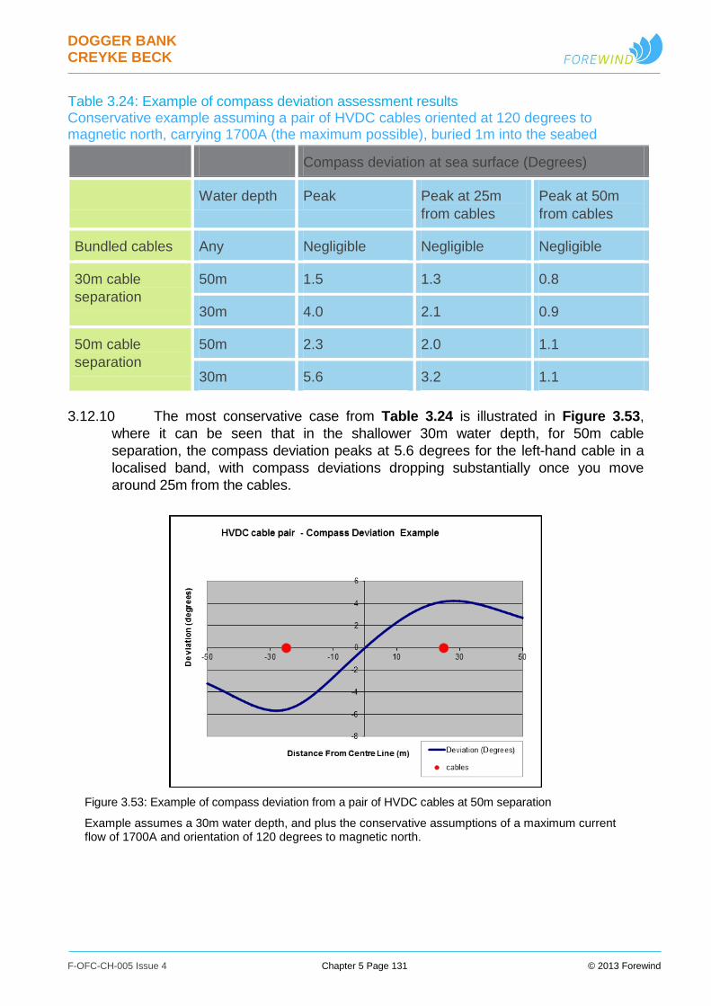
DOGGER BANK CREYKE BECK
F-OFC-CH-005 Issue 4 Chapter 5 Page 131 © 2013 Forewind
Table 3.24: Example of compass deviation assessment results Conservative example assuming a pair of HVDC cables oriented at 120 degrees to magnetic north, carrying 1700A (the maximum possible), buried 1m into the seabed
Compass deviation at sea surface (Degrees)
Water depth Peak Peak at 25m
from cables
Peak at 50m
from cables
Bundled cables Any Negligible Negligible Negligible
30m cable
separation
50m 1.5 1.3 0.8
30m 4.0 2.1 0.9
50m cable
separation
50m 2.3 2.0 1.1
30m 5.6 3.2 1.1
3.12.10 The most conservative case from Table 3.24 is illustrated in Figure 3.53,
where it can be seen that in the shallower 30m water depth, for 50m cable
separation, the compass deviation peaks at 5.6 degrees for the left-hand cable in a
localised band, with compass deviations dropping substantially once you move
around 25m from the cables.
Figure 3.53: Example of compass deviation from a pair of HVDC cables at 50m separation
Example assumes a 30m water depth, and plus the conservative assumptions of a maximum current flow of 1700A and orientation of 120 degrees to magnetic north.
DOGGER BANK CREYKE BECK
F-OFC-CH-005 Issue 4 Chapter 5 Page 132 © 2013 Forewind
Offshore EMF Assessment Conclusions (DC Cables Only)
3.12.11 The offshore DC export cables from the Dogger Bank Zone to the landfall
north of Ulrome will generate magnetic fields, but no external electric fields.
3.12.12 As shown above, under some circumstances, EMFs produced by DC cables
can interfere with vessel navigation systems by causing magnetic compass deviation
in their immediate vicinity. These effects have been shown to be highly localised and
may occur only in shallower waters (less than around 30m water depth) and for
restricted zones on the surface (indicatively less than 100m wide) immediately above
any unbundled cables. Bundling the cables will address this effect by reducing the
EMFs produced by the cables such that compass deviation is reduced to negligible
levels.
3.12.13 Significant compass deviations may therefore occur only with unbundled
cables buried in shallower waters, and thus are only possible in the vicinity of the
landfall, where the cables will be split for HDD installation, and any other areas where
waters are shallow and unbundling the cables is also necessary. The magnitude of
any compass deviation is also significantly affected by the spacing of cable pairs, and
the orientation of cables, and will only reach the values stated within the examples
above when the wind farm is at peak output. The results of this assessment are
considered further within Chapter 16 Shipping and Navigation.
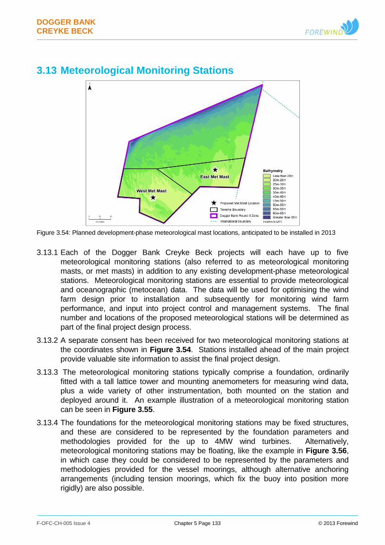
DOGGER BANK CREYKE BECK
F-OFC-CH-005 Issue 4 Chapter 5 Page 133 © 2013 Forewind
3.13 Meteorological Monitoring Stations
Figure 3.54: Planned development-phase meteorological mast locations, anticipated to be installed in 2013
3.13.1 Each of the Dogger Bank Creyke Beck projects will each have up to five
meteorological monitoring stations (also referred to as meteorological monitoring
masts, or met masts) in addition to any existing development-phase meteorological
stations. Meteorological monitoring stations are essential to provide meteorological
and oceanographic (metocean) data. The data will be used for optimising the wind
farm design prior to installation and subsequently for monitoring wind farm
performance, and input into project control and management systems. The final
number and locations of the proposed meteorological stations will be determined as
part of the final project design process.
3.13.2 A separate consent has been received for two meteorological monitoring stations at
the coordinates shown in Figure 3.54. Stations installed ahead of the main project
provide valuable site information to assist the final project design.
3.13.3 The meteorological monitoring stations typically comprise a foundation, ordinarily
fitted with a tall lattice tower and mounting anemometers for measuring wind data,
plus a wide variety of other instrumentation, both mounted on the station and
deployed around it. An example illustration of a meteorological monitoring station
can be seen in Figure 3.55.
3.13.4 The foundations for the meteorological monitoring stations may be fixed structures,
and these are considered to be represented by the foundation parameters and
methodologies provided for the up to 4MW wind turbines. Alternatively,
meteorological monitoring stations may be floating, like the example in Figure 3.56,
in which case they could be considered to be represented by the parameters and
methodologies provided for the vessel moorings, although alternative anchoring
arrangements (including tension moorings, which fix the buoy into position more
rigidly) are also possible.
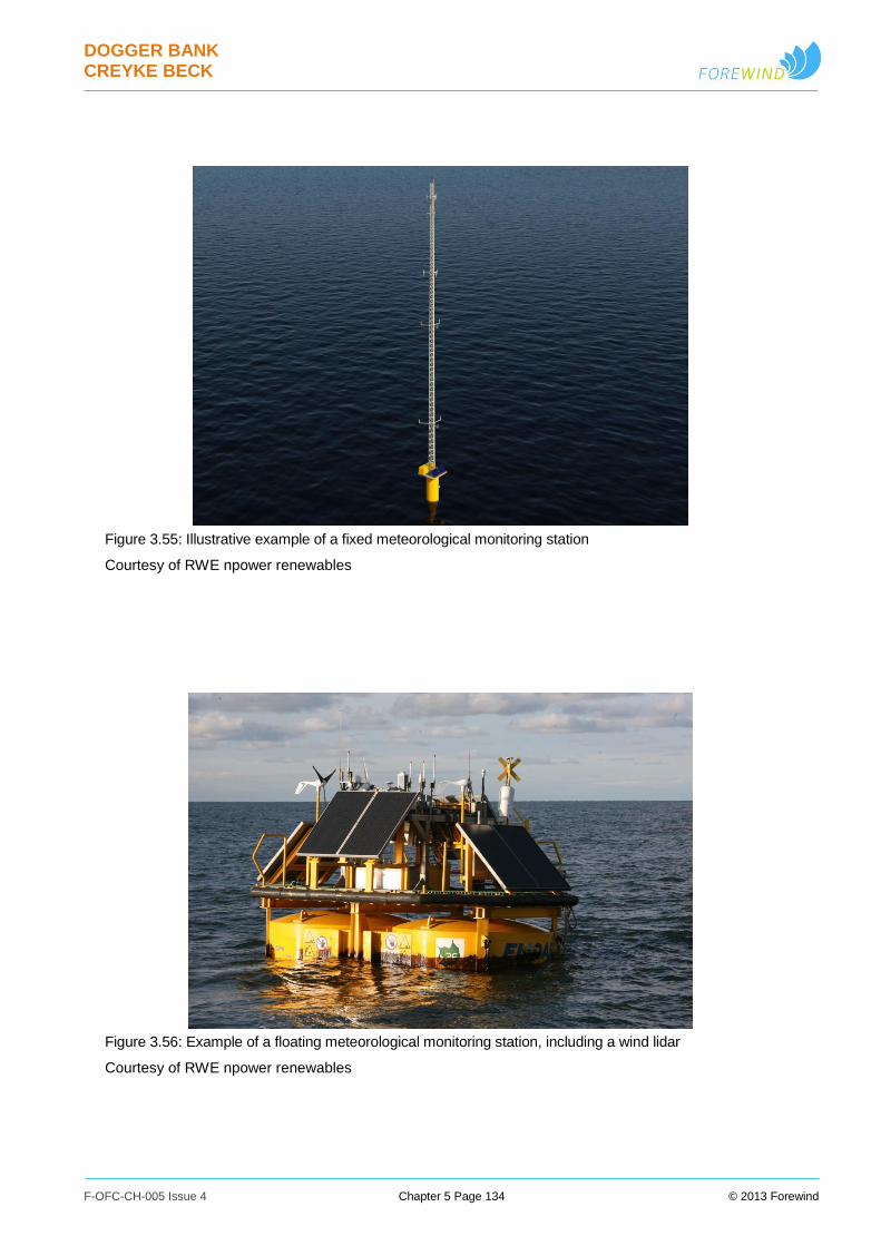
DOGGER BANK CREYKE BECK
F-OFC-CH-005 Issue 4 Chapter 5 Page 134 © 2013 Forewind
Figure 3.55: Illustrative example of a fixed meteorological monitoring station
Courtesy of RWE npower renewables
Figure 3.56: Example of a floating meteorological monitoring station, including a wind lidar
Courtesy of RWE npower renewables
DOGGER BANK CREYKE BECK
F-OFC-CH-005 Issue 4 Chapter 5 Page 135 © 2013 Forewind
3.13.5 The meteorological monitoring stations may typically include a range of the following
elements:
Lattice tower (up to the maximum tip height of the wind turbines, although hub
height is more common) although a tower is not always necessary, for instance
in stations based around wind lidar remote sensing systems;
Anemometers and other meteorological sensors, potentially including wind lidar
systems;
Oceanographic sensors, on the structure or potentially deployed on the seabed
in the immediate proximity of the station;
Power supply and generation equipment including photovoltaic cells, small wind
generators, battery banks, diesel generators, fuel cells, and associated fuel;
Control, data recording, and communication equipment;
Cables for connection to the wind farm power and control systems network,
discussed further within Section 3.8 Offshore Cables; and
Navigation, aviation, and safety marking and lighting.
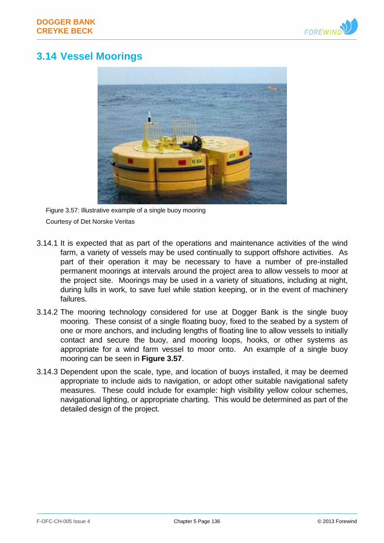
DOGGER BANK CREYKE BECK
F-OFC-CH-005 Issue 4 Chapter 5 Page 136 © 2013 Forewind
3.14 Vessel Moorings
3.14.1 It is expected that as part of the operations and maintenance activities of the wind
farm, a variety of vessels may be used continually to support offshore activities. As
part of their operation it may be necessary to have a number of pre-installed
permanent moorings at intervals around the project area to allow vessels to moor at
the project site. Moorings may be used in a variety of situations, including at night,
during lulls in work, to save fuel while station keeping, or in the event of machinery
failures.
3.14.2 The mooring technology considered for use at Dogger Bank is the single buoy
mooring. These consist of a single floating buoy, fixed to the seabed by a system of
one or more anchors, and including lengths of floating line to allow vessels to initially
contact and secure the buoy, and mooring loops, hooks, or other systems as
appropriate for a wind farm vessel to moor onto. An example of a single buoy
mooring can be seen in Figure 3.57.
3.14.3 Dependent upon the scale, type, and location of buoys installed, it may be deemed
appropriate to include aids to navigation, or adopt other suitable navigational safety
measures. These could include for example: high visibility yellow colour schemes,
navigational lighting, or appropriate charting. This would be determined as part of the
detailed design of the project.
Figure 3.57: Illustrative example of a single buoy mooring
Courtesy of Det Norske Veritas

DOGGER BANK CREYKE BECK
F-OFC-CH-005 Issue 4 Chapter 5 Page 137 © 2013 Forewind
Figure 3.58: Illustrative example of a single buoy mooring with six gravity anchors
3.14.4 The buoys themselves would typically be constructed of steel or plastic. Various
shapes are possible, including cylindrical or spherical. The buoys would be secured
to the seabed using a variety of anchor systems, potentially including drag anchors
(‘traditional’ anchors), plate anchors, suction pile anchors, or gravity anchors. The
chains securing the buoy to the anchors will contact the seabed. Figure 3.58 shows
an example of a possible anchor and chain arrangement for a single buoy mooring.
3.14.5 The parameters considered for mooring buoys are listed in Table 3.25.
Table 3.25: Indicative mooring buoy parameters
Parameter Creyke Beck A Creyke Beck B
Maximum number of vessel
moorings per project
10 10
Indicative buoy diameter (m) 6 6
Maximum number of
anchors per vessel mooring
6 6
Maximum seabed impact
footprint of all buoys, per
project (km2)
0.4720 0.4720
3.14.6 Each mooring buoy will be fabricated and assembled and transported to site
(potentially via a lay-down area at a selected construction port). A brief typical
installation sequence is as follows:
i. Transport of buoys to offshore site using a vessel such as an anchor handler;
ii. Installation of the mooring’s anchors into the seabed in predefined positions. For
drag or pull anchors this is typically by dragging or pulling until they are fully

DOGGER BANK CREYKE BECK
F-OFC-CH-005 Issue 4 Chapter 5 Page 138 © 2013 Forewind
embedded into the seabed; suction piles are typically embedded in a manner similar
to that used for wind turbine suction bucket foundations; and gravity anchors are
craned into position on the seabed.
iii. Deployment of the mooring buoy and associated components, and connection onto
the pre-installed anchors.
3.14.7 The sequence is repeated for each buoy.
DOGGER BANK CREYKE BECK
F-OFC-CH-005 Issue 4 Chapter 5 Page 139 © 2013 Forewind
4 Onshore Project Components
4.1 Cable Landfall
4.1.1 The offshore export cables will come ashore at landfall to connect to the onshore
export cable systems. The cable landfall works, including the methods of installation,
will depend on the geology of the landfall point, the height of the cliffs under which
the landfall cable has to pass and any local environmental considerations.
4.1.2 There are a number of techniques which may be utilised to bring the project offshore
export cables ashore. In order to minimise the disruption on the shoreline caused by
open trenching the assessed construction method is to use the horizontal directional
drilling (HDD) technique. Landfall HDD operations are anticipated to be undertaken
starting from the transition bay location, drilling under the cliffs and beach, then
exiting in the seabed. In some cases it may be necessary for the HDD to exit on the
beach in the inter-tidal area, and the additional works potentially required for this
option are described below.
4.1.3 HDD techniques are also used for onshore installation and details of HDD operations
are therefore given in Section 4.4 Cable installation. Other cable installation
techniques are also described in Section 4.4 Cable installation.
Cable Transition Bay
4.1.4 The offshore cables will be connected to the onshore cables in one or more
specifically designed underground joint bays, or pits, referred to as transition bays.
The transition bay location will be carefully chosen, on dry land, and buried below
ground. The selection of the position of the transition bay(s), and the landfall works
in general, must also take into account local coastal erosion which is a feature of the
Dogger Bank Creyke Beck landfall area.
4.1.5 Typical transition bay dimensions are approximately 1.5m depth, 4m width and 12m
length. Dimensions may vary depending on the final electrical design
4.1.6 After installation and jointing of the cables at the transition bay it will be backfilled and
the top surface reinstated. There will be no above ground structures and the ground
can be returned to previous use.
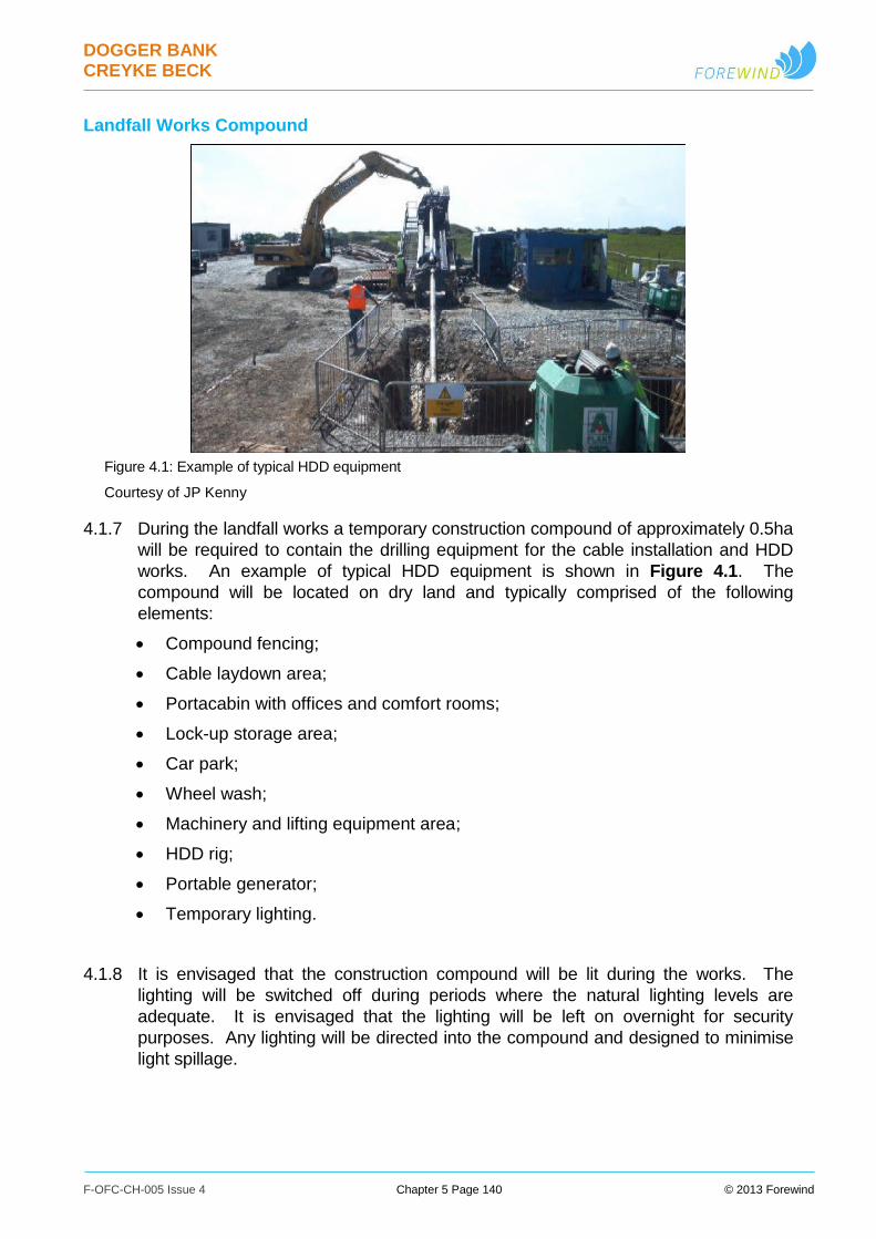
DOGGER BANK CREYKE BECK
F-OFC-CH-005 Issue 4 Chapter 5 Page 140 © 2013 Forewind
Landfall Works Compound
Figure 4.1: Example of typical HDD equipment
Courtesy of JP Kenny
4.1.7 During the landfall works a temporary construction compound of approximately 0.5ha
will be required to contain the drilling equipment for the cable installation and HDD
works. An example of typical HDD equipment is shown in Figure 4.1. The
compound will be located on dry land and typically comprised of the following
elements:
Compound fencing;
Cable laydown area;
Portacabin with offices and comfort rooms;
Lock-up storage area;
Car park;
Wheel wash;
Machinery and lifting equipment area;
HDD rig;
Portable generator;
Temporary lighting.
4.1.8 It is envisaged that the construction compound will be lit during the works. The
lighting will be switched off during periods where the natural lighting levels are
adequate. It is envisaged that the lighting will be left on overnight for security
purposes. Any lighting will be directed into the compound and designed to minimise
light spillage.
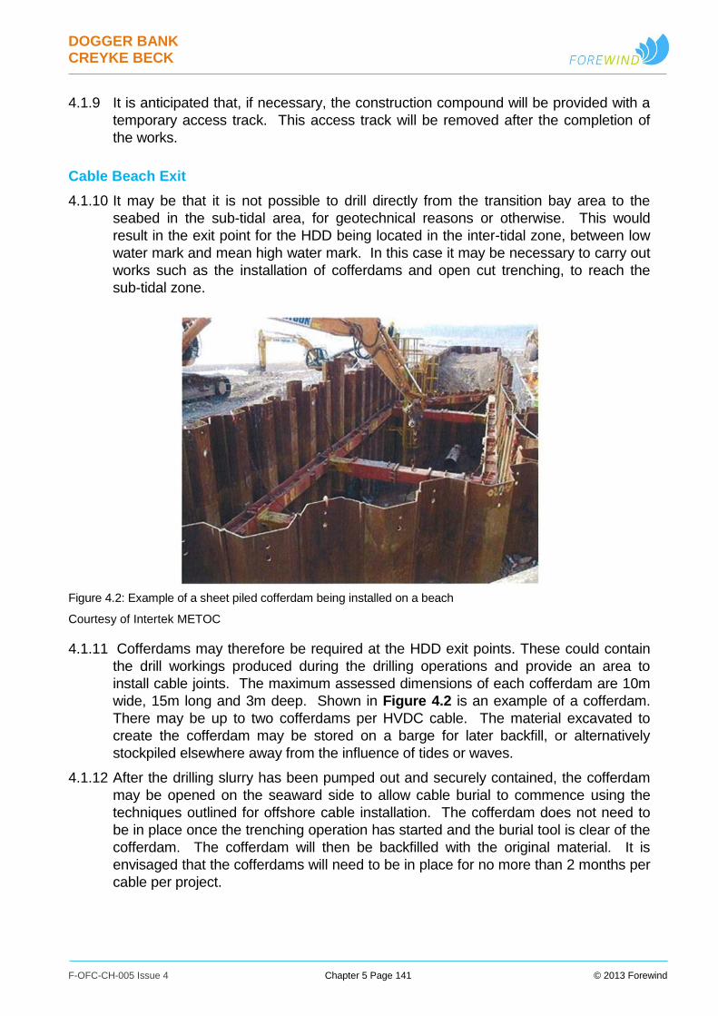
DOGGER BANK CREYKE BECK
F-OFC-CH-005 Issue 4 Chapter 5 Page 141 © 2013 Forewind
4.1.9 It is anticipated that, if necessary, the construction compound will be provided with a
temporary access track. This access track will be removed after the completion of
the works.
Cable Beach Exit
4.1.10 It may be that it is not possible to drill directly from the transition bay area to the
seabed in the sub-tidal area, for geotechnical reasons or otherwise. This would
result in the exit point for the HDD being located in the inter-tidal zone, between low
water mark and mean high water mark. In this case it may be necessary to carry out
works such as the installation of cofferdams and open cut trenching, to reach the
sub-tidal zone.
4.1.11 Cofferdams may therefore be required at the HDD exit points. These could contain
the drill workings produced during the drilling operations and provide an area to
install cable joints. The maximum assessed dimensions of each cofferdam are 10m
wide, 15m long and 3m deep. Shown in Figure 4.2 is an example of a cofferdam.
There may be up to two cofferdams per HVDC cable. The material excavated to
create the cofferdam may be stored on a barge for later backfill, or alternatively
stockpiled elsewhere away from the influence of tides or waves.
4.1.12 After the drilling slurry has been pumped out and securely contained, the cofferdam
may be opened on the seaward side to allow cable burial to commence using the
techniques outlined for offshore cable installation. The cofferdam does not need to
be in place once the trenching operation has started and the burial tool is clear of the
cofferdam. The cofferdam will then be backfilled with the original material. It is
envisaged that the cofferdams will need to be in place for no more than 2 months per
cable per project.
Figure 4.2: Example of a sheet piled cofferdam being installed on a beach
Courtesy of Intertek METOC

DOGGER BANK CREYKE BECK
F-OFC-CH-005 Issue 4 Chapter 5 Page 142 © 2013 Forewind
4.1.13 In the case of the seaward HDD exit hole being located on the beach within the inter-
tidal zone, the cable installation may also be carried out using techniques such as
open cut trenching to a point where installation can continue using the techniques
outlined for the offshore cable installation.
4.2 Onshore Cables
4.2.1 It has been determined that for the Dogger Bank Creyke Beck projects all the
onshore cables will be buried and the use of electric overhead lines is excluded.
4.2.2 The cable parameters provided are based upon open trench installation of cables at
a depth of approximately 1.2m. The cables will be mainly laid in open cut trenches
either directly buried or in ducts. The trenches will be backfilled with material of
adequate thermal resistivity, to dissipate the heat generated in the cables made of
either native soil or stabilised material such as CBS (Cement Bound Sand). For parts
of the cable route the cables will be installed through HDD (Horizontal Directional
Drilling), which is the standard method used for obstacle crossing. Therefore the
cable parameters provided below are indicative only and information such as cable
weight and conductor material will be subject to change depending on the method of
installation, ground conditions, manufacturer, and the detailed electrical design.
4.2.3 The size of the onshore underground cables used for Dogger Bank Creyke Beck will
be subject to detailed electrical and thermal design analysis. This will be carried out
as part of the detailed design in consultation with specialist cable manufacturers.
However, Forewind has estimated the expected cable dimensions based on
information currently available.
Onshore HVDC Cables
4.2.4 It is envisioned that the onshore HVDC cables will likely be single core, unarmoured,
aluminium or copper conductor cables, suitable for underground installation. The
nominal voltage is currently envisaged to be ±320kV, however higher voltages up to
±550kV may be used, following cable technology developments. Table 4.1 shows
indicative parameters for the HVDC cables that may be used for each project.
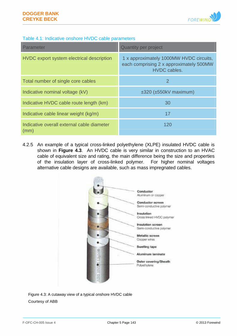
DOGGER BANK CREYKE BECK
F-OFC-CH-005 Issue 4 Chapter 5 Page 143 © 2013 Forewind
Table 4.1: Indicative onshore HVDC cable parameters
Parameter Quantity per project
HVDC export system electrical description 1 x approximately 1000MW HVDC circuits,
each comprising 2 x approximately 500MW
HVDC cables.
Total number of single core cables 2
Indicative nominal voltage (kV) ±320 (±550kV maximum)
Indicative HVDC cable route length (km) 30
Indicative cable linear weight (kg/m) 17
Indicative overall external cable diameter
(mm)
120
4.2.5 An example of a typical cross-linked polyethylene (XLPE) insulated HVDC cable is
shown in Figure 4.3. An HVDC cable is very similar in construction to an HVAC
cable of equivalent size and rating, the main difference being the size and properties
of the insulation layer of cross-linked polymer. For higher nominal voltages
alternative cable designs are available, such as mass impregnated cables.
Figure 4.3: A cutaway view of a typical onshore HVDC cable
Courtesy of ABB
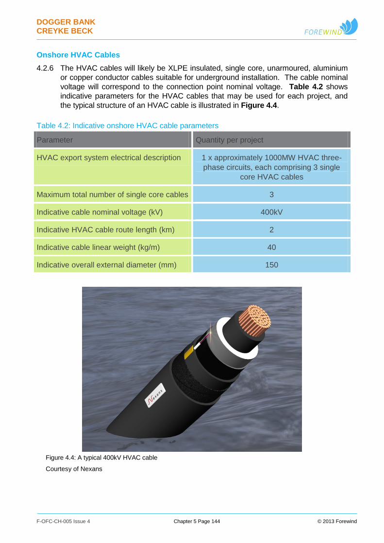
DOGGER BANK CREYKE BECK
F-OFC-CH-005 Issue 4 Chapter 5 Page 144 © 2013 Forewind
Onshore HVAC Cables
4.2.6 The HVAC cables will likely be XLPE insulated, single core, unarmoured, aluminium
or copper conductor cables suitable for underground installation. The cable nominal
voltage will correspond to the connection point nominal voltage. Table 4.2 shows
indicative parameters for the HVAC cables that may be used for each project, and
the typical structure of an HVAC cable is illustrated in Figure 4.4.
Table 4.2: Indicative onshore HVAC cable parameters
Parameter Quantity per project
HVAC export system electrical description 1 x approximately 1000MW HVAC three-
phase circuits, each comprising 3 single
core HVAC cables
Maximum total number of single core cables 3
Indicative cable nominal voltage (kV) 400kV
Indicative HVAC cable route length (km) 2
Indicative cable linear weight (kg/m) 40
Indicative overall external diameter (mm) 150
Figure 4.4: A typical 400kV HVAC cable
Courtesy of Nexans
DOGGER BANK CREYKE BECK
F-OFC-CH-005 Issue 4 Chapter 5 Page 145 © 2013 Forewind
Onshore Electromagnetic Fields
4.2.7 This section summarises the impact of EMFs that would be generated by the
onshore assets of Dogger Bank Creyke Beck. These comprise as a maximum two
HVDC converter stations and HVAC connection equipment, two sets of underground
HVAC cables and two sets of underground HVDC cables, as described within this
Chapter.
4.2.8 The assessment of the impact of any EMFs generated by the projects follows the
National Policy Statement guidance on decision making for Electric and Magnetic
Fields. Also see the Health Impact Assessment, contained in Appendix 5.C Health
Impact Assessment.
4.2.9 As there will be no overhead lines connecting to the converter stations, only
underground cables, there will be no electric fields generated as cable screening
eliminates external electric fields. The cables will produce magnetic fields, but these
will be within Health Protection Agency and other relevant regulatory guidelines.
4.2.10 The converter stations will generate electric fields from the above ground conductors,
but these are small in comparison to overhead lines and are contained within the
perimeter of the station or at most fall away to zero within the first few metres of the
perimeter fence.
4.3 Onshore Cable Routes
Onshore Cable Routes Overview
4.3.1 The onshore cable systems will be buried underground for the entire length of their
routes. Forewind has ruled out the use of overhead line connections for a number of
reasons, which include the associated landscape and visual impact.
4.3.2 The installation will be made predominantly on farmland through conventional trench
installation, either direct buried or in ducts. However the cables will cross a number
of obstacles such as minor and major roads, railways, woodlands etc., for which
alternative installation methods will be considered. Depending on the length and
features of the crossing, trenchless installation techniques will be considered, such
as horizontal directional drilling (HDD). These will be identified in the final detailed
design process. Cable installation methods are discussed in Section 4.4 Cable
installation.
4.3.3 The topography of the route is predominately low-lying arable fields, used mainly for
growing crops. There are three major roads to cross on the route and a number of
minor and unclassified roads as well. In addition there are a number of large
watercourses such as the Leven Canal and the River Hull and numerous field drains
of varying widths and depths both named and un-named. There is also a Network
Rail line, two high pressure gas pipelines, and other utility service providers such as
electricity both overhead and underground, water, sewage, gas and
telecommunications. At Woodmansey, the route traverses through Common Land at
Figham Pastures.
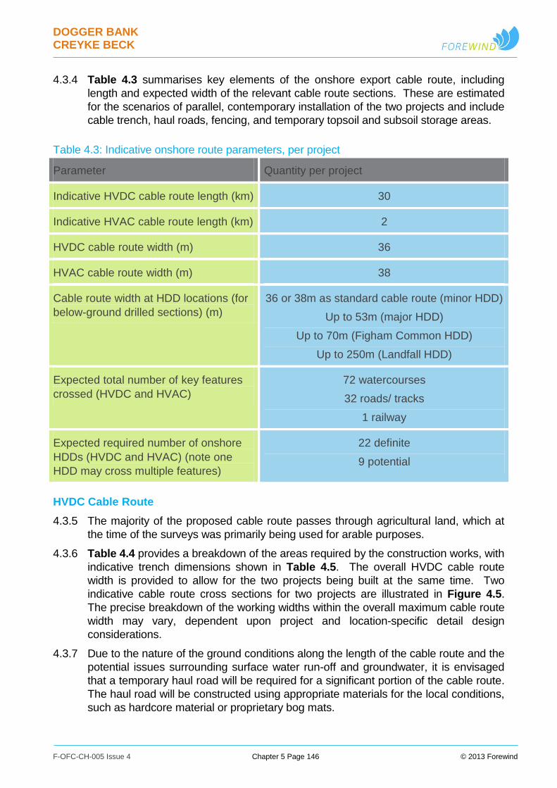
DOGGER BANK CREYKE BECK
F-OFC-CH-005 Issue 4 Chapter 5 Page 146 © 2013 Forewind
4.3.4 Table 4.3 summarises key elements of the onshore export cable route, including
length and expected width of the relevant cable route sections. These are estimated
for the scenarios of parallel, contemporary installation of the two projects and include
cable trench, haul roads, fencing, and temporary topsoil and subsoil storage areas.
Table 4.3: Indicative onshore route parameters, per project
Parameter Quantity per project
Indicative HVDC cable route length (km) 30
Indicative HVAC cable route length (km) 2
HVDC cable route width (m) 36
HVAC cable route width (m) 38
Cable route width at HDD locations (for
below-ground drilled sections) (m)
36 or 38m as standard cable route (minor HDD)
Up to 53m (major HDD)
Up to 70m (Figham Common HDD)
Up to 250m (Landfall HDD)
Expected total number of key features
crossed (HVDC and HVAC)
72 watercourses
32 roads/ tracks
1 railway
Expected required number of onshore
HDDs (HVDC and HVAC) (note one
HDD may cross multiple features)
22 definite
9 potential
HVDC Cable Route
4.3.5 The majority of the proposed cable route passes through agricultural land, which at
the time of the surveys was primarily being used for arable purposes.
4.3.6 Table 4.4 provides a breakdown of the areas required by the construction works, with
indicative trench dimensions shown in Table 4.5. The overall HVDC cable route
width is provided to allow for the two projects being built at the same time. Two
indicative cable route cross sections for two projects are illustrated in Figure 4.5.
The precise breakdown of the working widths within the overall maximum cable route
width may vary, dependent upon project and location-specific detail design
considerations.
4.3.7 Due to the nature of the ground conditions along the length of the cable route and the
potential issues surrounding surface water run-off and groundwater, it is envisaged
that a temporary haul road will be required for a significant portion of the cable route.
The haul road will be constructed using appropriate materials for the local conditions,
such as hardcore material or proprietary bog mats.
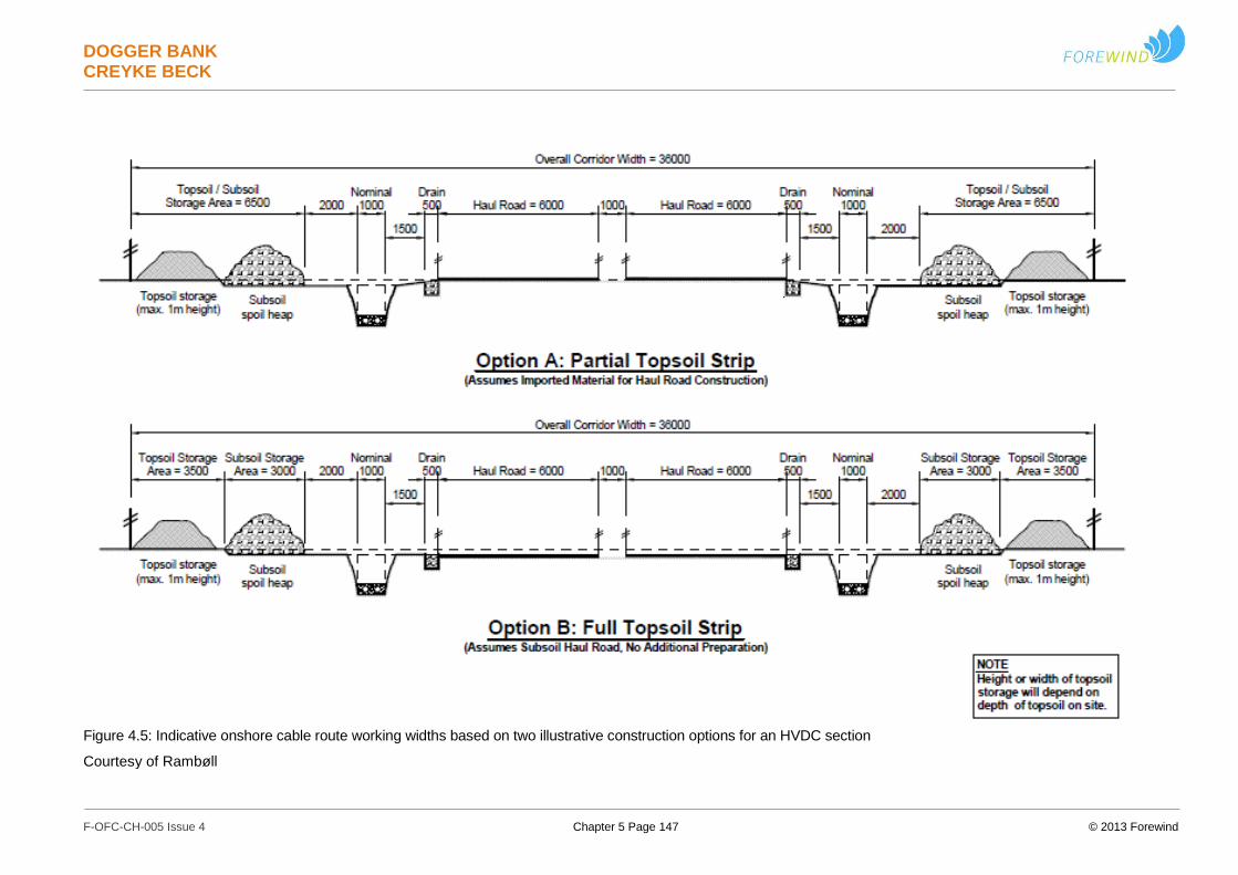
DOGGER BANK CREYKE BECK
F-OFC-CH-005 Issue 4 Chapter 5 Page 147 © 2013 Forewind
Figure 4.5: Indicative onshore cable route working widths based on two illustrative construction options for an HVDC section
Courtesy of Rambøll
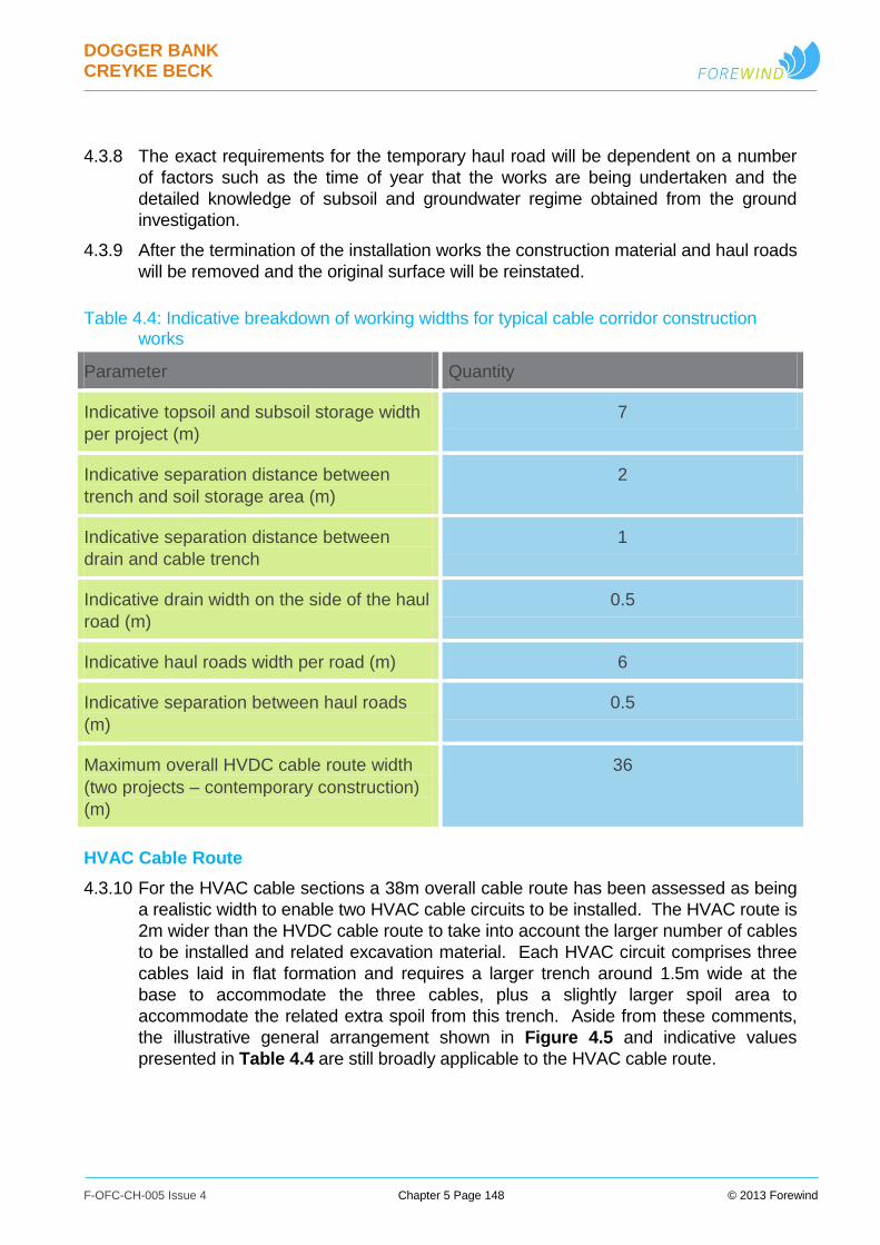
DOGGER BANK CREYKE BECK
F-OFC-CH-005 Issue 4 Chapter 5 Page 148 © 2013 Forewind
4.3.8 The exact requirements for the temporary haul road will be dependent on a number
of factors such as the time of year that the works are being undertaken and the
detailed knowledge of subsoil and groundwater regime obtained from the ground
investigation.
4.3.9 After the termination of the installation works the construction material and haul roads
will be removed and the original surface will be reinstated.
Table 4.4: Indicative breakdown of working widths for typical cable corridor construction works
Parameter Quantity
Indicative topsoil and subsoil storage width
per project (m)
7
Indicative separation distance between
trench and soil storage area (m)
2
Indicative separation distance between
drain and cable trench
1
Indicative drain width on the side of the haul
road (m)
0.5
Indicative haul roads width per road (m) 6
Indicative separation between haul roads
(m)
0.5
Maximum overall HVDC cable route width
(two projects – contemporary construction)
(m)
36
HVAC Cable Route
4.3.10 For the HVAC cable sections a 38m overall cable route has been assessed as being
a realistic width to enable two HVAC cable circuits to be installed. The HVAC route is
2m wider than the HVDC cable route to take into account the larger number of cables
to be installed and related excavation material. Each HVAC circuit comprises three
cables laid in flat formation and requires a larger trench around 1.5m wide at the
base to accommodate the three cables, plus a slightly larger spoil area to
accommodate the related extra spoil from this trench. Aside from these comments,
the illustrative general arrangement shown in Figure 4.5 and indicative values
presented in Table 4.4 are still broadly applicable to the HVAC cable route.
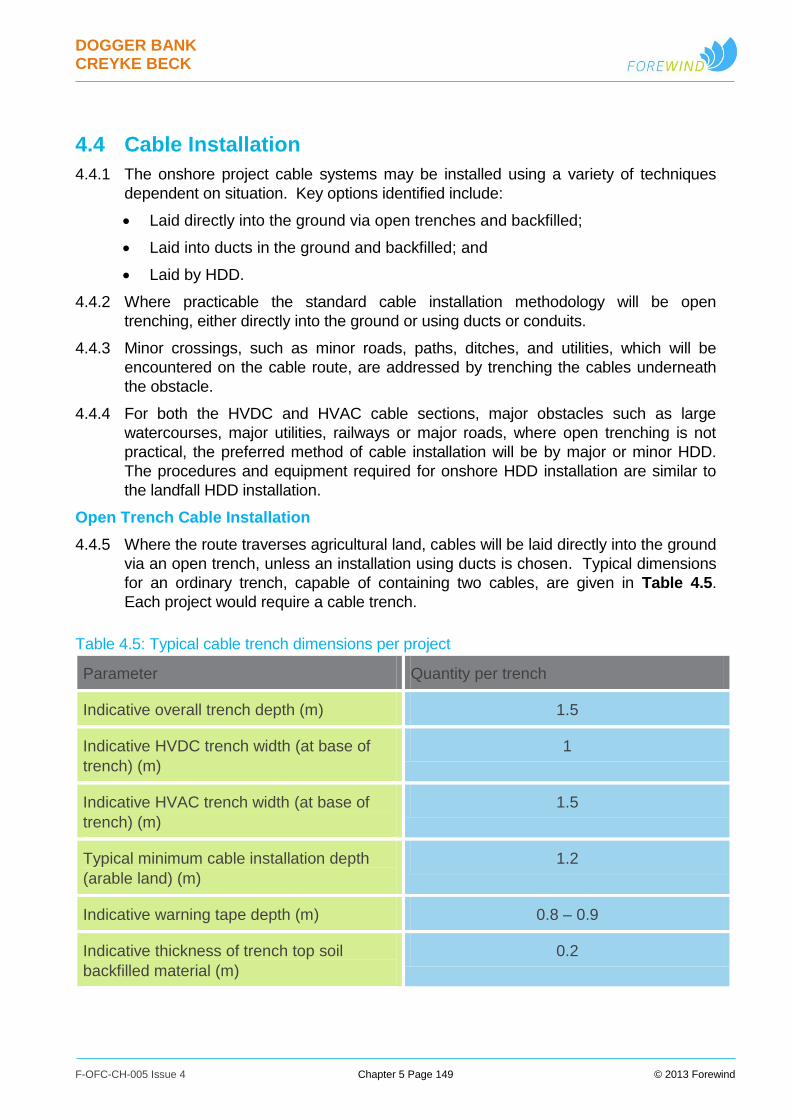
DOGGER BANK CREYKE BECK
F-OFC-CH-005 Issue 4 Chapter 5 Page 149 © 2013 Forewind
4.4 Cable Installation
4.4.1 The onshore project cable systems may be installed using a variety of techniques
dependent on situation. Key options identified include:
Laid directly into the ground via open trenches and backfilled;
Laid into ducts in the ground and backfilled; and
Laid by HDD.
4.4.2 Where practicable the standard cable installation methodology will be open
trenching, either directly into the ground or using ducts or conduits.
4.4.3 Minor crossings, such as minor roads, paths, ditches, and utilities, which will be
encountered on the cable route, are addressed by trenching the cables underneath
the obstacle.
4.4.4 For both the HVDC and HVAC cable sections, major obstacles such as large
watercourses, major utilities, railways or major roads, where open trenching is not
practical, the preferred method of cable installation will be by major or minor HDD.
The procedures and equipment required for onshore HDD installation are similar to
the landfall HDD installation.
Open Trench Cable Installation
4.4.5 Where the route traverses agricultural land, cables will be laid directly into the ground
via an open trench, unless an installation using ducts is chosen. Typical dimensions
for an ordinary trench, capable of containing two cables, are given in Table 4.5.
Each project would require a cable trench.
Table 4.5: Typical cable trench dimensions per project
Parameter Quantity per trench
Indicative overall trench depth (m) 1.5
Indicative HVDC trench width (at base of
trench) (m)
1
Indicative HVAC trench width (at base of
trench) (m)
1.5
Typical minimum cable installation depth
(arable land) (m)
1.2
Indicative warning tape depth (m) 0.8 – 0.9
Indicative thickness of trench top soil
backfilled material (m)
0.2
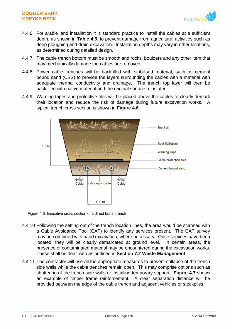
DOGGER BANK CREYKE BECK
F-OFC-CH-005 Issue 4 Chapter 5 Page 150 © 2013 Forewind
4.4.6 For arable land installation it is standard practice to install the cables at a sufficient
depth, as shown in Table 4.5, to prevent damage from agricultural activities such as
deep ploughing and drain excavation. Installation depths may vary in other locations,
as determined during detailed design.
4.4.7 The cable trench bottom must be smooth and rocks, boulders and any other item that
may mechanically damage the cables are removed.
4.4.8 Power cable trenches will be backfilled with stabilised material, such as cement
bound sand (CBS) to provide the layers surrounding the cables with a material with
adequate thermal conductivity and drainage. The trench top layer will then be
backfilled with native material and the original surface reinstated.
4.4.9 Warning tapes and protective tiles will be placed above the cables to clearly demark
their location and reduce the risk of damage during future excavation works. A
typical trench cross section is shown in Figure 4.6.
Figure 4.6: Indicative cross section of a direct burial trench
4.4.10 Following the setting out of the trench location lines, the area would be scanned with
a Cable Avoidance Tool (CAT) to identify any services present. The CAT survey
may be combined with hand excavation, where necessary. Once services have been
located, they will be clearly demarcated at ground level. In certain areas, the
presence of contaminated material may be encountered during the excavation works.
These shall be dealt with as outlined in Section 7.2 Waste Management.
4.4.11 The contractor will use all the appropriate measures to prevent collapse of the trench
side walls while the cable trenches remain open. This may comprise options such as
shuttering of the trench side walls or installing temporary support. Figure 4.7 shows
an example of timber frame reinforcement. A clear separation distance will be
provided between the edge of the cable trench and adjacent vehicles or stockpiles.
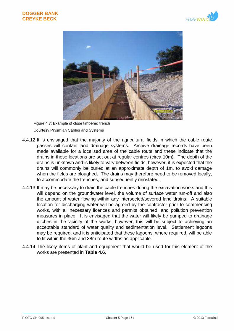
DOGGER BANK CREYKE BECK
F-OFC-CH-005 Issue 4 Chapter 5 Page 151 © 2013 Forewind
Figure 4.7: Example of close timbered trench
Courtesy Prysmian Cables and Systems
4.4.12 It is envisaged that the majority of the agricultural fields in which the cable route
passes will contain land drainage systems. Archive drainage records have been
made available for a localised area of the cable route and these indicate that the
drains in these locations are set out at regular centres (circa 10m). The depth of the
drains is unknown and is likely to vary between fields, however, it is expected that the
drains will commonly be buried at an approximate depth of 1m, to avoid damage
when the fields are ploughed. The drains may therefore need to be removed locally,
to accommodate the trenches, and subsequently reinstated.
4.4.13 It may be necessary to drain the cable trenches during the excavation works and this
will depend on the groundwater level, the volume of surface water run-off and also
the amount of water flowing within any intersected/severed land drains. A suitable
location for discharging water will be agreed by the contractor prior to commencing
works, with all necessary licences and permits obtained, and pollution prevention
measures in place. It is envisaged that the water will likely be pumped to drainage
ditches in the vicinity of the works; however, this will be subject to achieving an
acceptable standard of water quality and sedimentation level. Settlement lagoons
may be required, and it is anticipated that these lagoons, where required, will be able
to fit within the 36m and 38m route widths as applicable.
4.4.14 The likely items of plant and equipment that would be used for this element of the
works are presented in Table 4.6.
DOGGER BANK CREYKE BECK
F-OFC-CH-005 Issue 4 Chapter 5 Page 152 © 2013 Forewind
Table 4.6: Plant and Vehicles indicatively required for trench excavation
Likely items of plant/vehicles to be used for
activity Specific Use
Personnel Vehicles Site staff arriving / leaving site
CAT scanner Scanning for buried services
360⁰ Tracked/wheeled excavators Excavating trenches and stockpiling
materials
Dumper (5t) Distributing subsoil
Water pumps Draining water from within cable trenches
Generators Power for water pumps
Wheel wash Cleaning outgoing vehicles
Road sweeper Cleaning local roads
Ducted Cable Installation
4.4.15 For sections of the cable route the cables may be installed using ducts. Ducts can
increase the cable mechanical protection and provide greater installation flexibility.
Furthermore, ducts are always used for HDD installation.
4.4.16 The use of ducts for increased installation flexibility will be dependent on the
construction scenario used, as described in Section 6.3 Construction, and whether
enabling actions are being undertaken for the second project.
4.4.17 In order to reduce the footprint and length of time required for cable installation, ducts
and all associated civil works, could be installed prior to the installation of the cables,
which will be pulled through the pre-installed ducts at a later stage. However, cable
ducting increases the thermal resistivity, therefore reducing the cable actual rating.
CBS or another stabilised material can be used in duct installation in order to
increase the rate of heat dissipation and increase the cable rating. Shown in Figure
4.8 is an indicative cross section of a ducted cable installation.
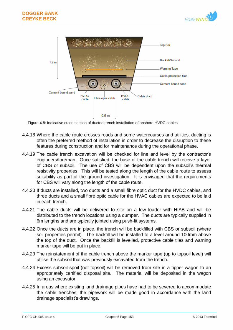
DOGGER BANK CREYKE BECK
F-OFC-CH-005 Issue 4 Chapter 5 Page 153 © 2013 Forewind
Figure 4.8: Indicative cross section of ducted trench installation of onshore HVDC cables
4.4.18 Where the cable route crosses roads and some watercourses and utilities, ducting is
often the preferred method of installation in order to decrease the disruption to these
features during construction and for maintenance during the operational phase.
4.4.19 The cable trench excavation will be checked for line and level by the contractor’s
engineers/foreman. Once satisfied, the base of the cable trench will receive a layer
of CBS or subsoil. The use of CBS will be dependent upon the subsoil’s thermal
resistivity properties. This will be tested along the length of the cable route to assess
suitability as part of the ground investigation. It is envisaged that the requirements
for CBS will vary along the length of the cable route.
4.4.20 If ducts are installed, two ducts and a small fibre optic duct for the HVDC cables, and
three ducts and a small fibre optic cable for the HVAC cables are expected to be laid
in each trench.
4.4.21 The cable ducts will be delivered to site on a low loader with HIAB and will be
distributed to the trench locations using a dumper. The ducts are typically supplied in
6m lengths and are typically jointed using push-fit systems.
4.4.22 Once the ducts are in place, the trench will be backfilled with CBS or subsoil (where
soil properties permit). The backfill will be installed to a level around 100mm above
the top of the duct. Once the backfill is levelled, protective cable tiles and warning
marker tape will be put in place.
4.4.23 The reinstatement of the cable trench above the marker tape (up to topsoil level) will
utilise the subsoil that was previously excavated from the trench.
4.4.24 Excess subsoil spoil (not topsoil) will be removed from site in a tipper wagon to an
appropriately certified disposal site. The material will be deposited in the wagon
using an excavator.
4.4.25 In areas where existing land drainage pipes have had to be severed to accommodate
the cable trenches, the pipework will be made good in accordance with the land
drainage specialist’s drawings.

DOGGER BANK CREYKE BECK
F-OFC-CH-005 Issue 4 Chapter 5 Page 154 © 2013 Forewind
Table 4.7: Plant and Vehicles indicatively required for installation of ducts
Likely items of plant/vehicles to be used for
activity Specific Use
Personnel Vehicles Site staff arriving / leaving site
Low loader /
HIAB wagon
Delivery of ducts
360⁰ Tracked excavators Trench backfilling
Dumper (5t) Distributing ducts, pipes, warning tiles,
marker tape
Eight wheel Tipper wagon Disposal of surplus material
Wheel wash Cleaning outgoing vehicles
Road sweeper Cleaning local roads
Horizontal Directional Drilling
4.4.26 Horizontal Directional Drilling, HDD, is a steerable trenchless method of installing
underground pipes, ducts and cables in a shallow arc along a prescribed bore path
by using a surface launched drilling rig. HDD is a well-established method for cable
installation where the more conventional trench installation is either unfeasible, or
undesirable for environmental reasons.
4.4.27 Pipe diameters which can be installed range from approximately 50mm to 1,000mm.
For HV cable installations using HDD, it is normal to install ducts of multiples of the
cable diameter to be pulled through the pipe or duct. This could result in bore
diameters up to around 450 to 600mm, although smaller diameters could be
possible, depending on the cable external diameter and length of duct.
4.4.28 Two sizes of HDD construction compounds, major and minor, are defined in Table
4.12, dependent upon the length and depth of the HDD required. For each HDD, the
cable route for the drilled (below-ground) sections, between the two end compounds,
will typically be no wider than the compounds themselves. In one case however, at
Figham Common where a longer and deeper HDD is required, the cables will need
additional separation over the drilled section, and thus the width may increase up to
70m. In addition, the landfall HDD will also need to be longer and deeper than at
other sites, and thus the below-ground width may increase up to 250m. Required
cable route widths are summarised in Table 4.3.
4.4.29 The typical activities required by an HDD operation are summarised below:
Site survey and bore planning;

DOGGER BANK CREYKE BECK
F-OFC-CH-005 Issue 4 Chapter 5 Page 155 © 2013 Forewind
Preparation of site for HDD operation;
HDD Drilling operation;
Demobilisation from site.
4.4.30 Prior to the commencement of HDD operations a site survey will be conducted. A
survey team will attend the site and map out the bore paths. Borehole surveys may
be undertaken to establish structural conditions for the drill path. The survey team
will create an accurate plan and elevations of the proposed duct route. During the
survey any buried services which are in close proximity to the route will be clearly
marked and documented on the survey drawings and where possible also on site.
4.4.31 A bore plan and profile will be created from the results of the survey. The plan will
provide final information on the proposed bore arc including entrance and exit points,
radius of curvature and the bore diameter required to accommodate the duct. The
plan will be used to determine the actual length of the bore. Information on all buried
services close to the bore path will also be contained within the bore plan and, where
necessary, the bore plan will be amended to avoid these services.
4.4.32 The likely items of plant and equipment that be used for this survey element of the
works are outlined in Table 4.8.
Table 4.8: Plant and vehicles indicatively required for HDD site survey and bore planning
Likely items of plant/vehicles to be used for
activity Specific Use
Personnel Vehicles Site manager and assistants
Transport vehicle and Percussion/rotary
core borehole rig on trailer
Transport and drilling staff.
Preparation of Site for HDD Operation
4.4.33 The surveyors will set out the launch and reception pits to be used for the HDD
operations. The dimensions and location of the launch and reception pits are
carefully planned.
4.4.34 A suitable access road and working platform at the launch and reception sites are
constructed to allow the set-up of the drilling equipment and easy access by support
vehicles. The requirements of both the launch site, where the drills are launched into
the ground, and the reception sites where the drills exit the ground, are outlined
below.

DOGGER BANK CREYKE BECK
F-OFC-CH-005 Issue 4 Chapter 5 Page 156 © 2013 Forewind
Launch Site
4.4.35 For the launch pit a rectangular area would be prepared, sized to suit the scale of the
HDD operation being undertaken.
4.4.36 Access to the site would be via an access road designed to accommodate heavily
loaded vehicles and heavy plant. Generally this will be the access road installed
alongside the trench for the majority of the route, and including watercourse
crossings via temporary vehicle bridges or similar.
4.4.37 A regular supply of fresh water will be required on site at all times either via a reliable
pumped source or frequent water tankers. If a continuous supply of water cannot be
provided then storage tanks may be required on site for water and adequate space
may be required for these.
4.4.38 Storage of slurry in a settling pond or disposal of excess slurry from site may be
required. Therefore, a pit/settling pond will be excavated at the launch site to contain
the slurry arisings from the HDD bore. This excavation pit/settling pond must have a
sufficient capacity to accommodate the drill arisings/slurry from the HDD operation
being undertaken. Tankers may be required during the operation to control the levels
of slurry and where necessary remove the slurry from the working area. Figure 4.9
shows the arrangement of a typical HDD launch site.
Figure 4.9: Typical arrangement of a large HDD launch site
Courtesy of Rambøll
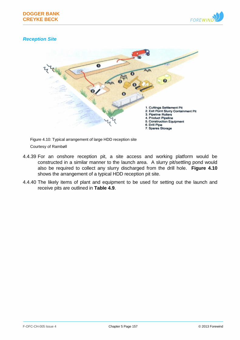
DOGGER BANK CREYKE BECK
F-OFC-CH-005 Issue 4 Chapter 5 Page 157 © 2013 Forewind
Reception Site
Figure 4.10: Typical arrangement of large HDD reception site
Courtesy of Rambøll
4.4.39 For an onshore reception pit, a site access and working platform would be
constructed in a similar manner to the launch area. A slurry pit/settling pond would
also be required to collect any slurry discharged from the drill hole. Figure 4.10
shows the arrangement of a typical HDD reception pit site.
4.4.40 The likely items of plant and equipment to be used for setting out the launch and
receive pits are outlined in Table 4.9.

DOGGER BANK CREYKE BECK
F-OFC-CH-005 Issue 4 Chapter 5 Page 158 © 2013 Forewind
Table 4.9: Plant and vehicles indicatively required for setting out pits
Likely items of plant/vehicles to be
used for activity Specific Use
Personnel Vehicles Site staff arriving / leaving site
Low loader /
HIAB wagon
Delivery of geotextiles/geogrid/pipes
for access and working area hardstanding
construction
Eight wheel Tipper wagon Delivery of hardcore for hardstanding construction /
removal of slurry pit material from working area.
360⁰ Tracked/wheeled excavators Distributing hardcore material and topsoil
strip/excavation of slurry pits
Bulldozer Distributing hardcore material and topsoil strip
Roller Compacting hardcore
Dumper (5t) Distributing ancillary items
4.4.41 Surface space requirements during operation need to be sufficient to allow access by
tankers to remove liquid slurry. Little working area is required for the drilling rig itself
during operation; however storage for materials and equipment will be necessary.
Should additives need to be introduced to the bore then area for a batching plant will
be required. Likewise, should recycling of the waste slurry be required then an area
should also be allowed for a recycling plant and/or a settlement lagoon. A suitable
working area will need to be allowed for excavators to remove slurry from the ground
surface.
4.4.42 At the receiving trench, working space will be required to construct the proposed
receiving duct. This needs to be constructed prior to the HDD operation
commencing.
HDD Drilling operation
4.4.43 Prior to drilling, the HDD rig will be elevated to the correct entry angle which will
conform to the angle on the bore plan. Once the correct angle is achieved the rig will
be anchored into position.
4.4.44 The HDD rig will first undertake a pilot bore using the drill head and involving the
injection of drilling fluid. The bore is then carried out in intervals which will be
determined by the contractor based on the specific HDD rig in use and the length of
the bore to be installed.
4.4.45 The depth and direction of the pilot bore will be closely monitored by the operator to
ensure that the bore follows the prescribed bore path. At each drill interval a locator
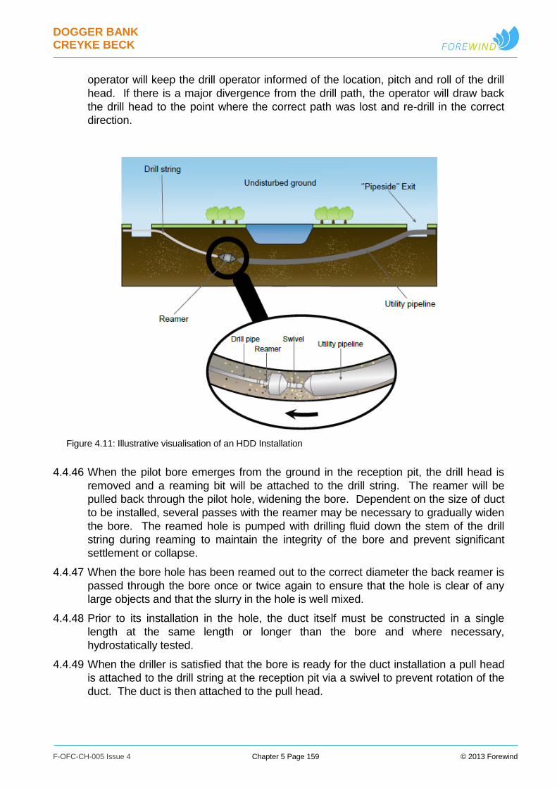
DOGGER BANK CREYKE BECK
F-OFC-CH-005 Issue 4 Chapter 5 Page 159 © 2013 Forewind
operator will keep the drill operator informed of the location, pitch and roll of the drill
head. If there is a major divergence from the drill path, the operator will draw back
the drill head to the point where the correct path was lost and re-drill in the correct
direction.
Figure 4.11: Illustrative visualisation of an HDD Installation
4.4.46 When the pilot bore emerges from the ground in the reception pit, the drill head is
removed and a reaming bit will be attached to the drill string. The reamer will be
pulled back through the pilot hole, widening the bore. Dependent on the size of duct
to be installed, several passes with the reamer may be necessary to gradually widen
the bore. The reamed hole is pumped with drilling fluid down the stem of the drill
string during reaming to maintain the integrity of the bore and prevent significant
settlement or collapse.
4.4.47 When the bore hole has been reamed out to the correct diameter the back reamer is
passed through the bore once or twice again to ensure that the hole is clear of any
large objects and that the slurry in the hole is well mixed.
4.4.48 Prior to its installation in the hole, the duct itself must be constructed in a single
length at the same length or longer than the bore and where necessary,
hydrostatically tested.
4.4.49 When the driller is satisfied that the bore is ready for the duct installation a pull head
is attached to the drill string at the reception pit via a swivel to prevent rotation of the
duct. The duct is then attached to the pull head.
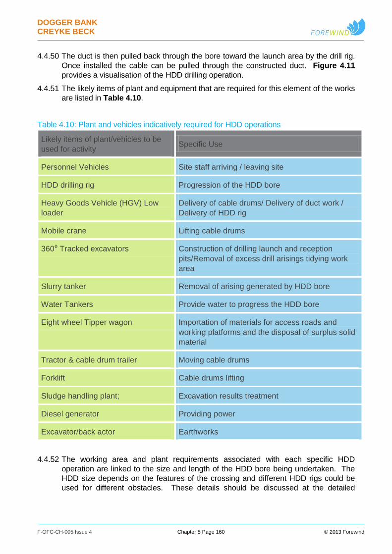
DOGGER BANK CREYKE BECK
F-OFC-CH-005 Issue 4 Chapter 5 Page 160 © 2013 Forewind
4.4.50 The duct is then pulled back through the bore toward the launch area by the drill rig.
Once installed the cable can be pulled through the constructed duct. Figure 4.11
provides a visualisation of the HDD drilling operation.
4.4.51 The likely items of plant and equipment that are required for this element of the works
are listed in Table 4.10.
Table 4.10: Plant and vehicles indicatively required for HDD operations
Likely items of plant/vehicles to be
used for activity Specific Use
Personnel Vehicles Site staff arriving / leaving site
HDD drilling rig Progression of the HDD bore
Heavy Goods Vehicle (HGV) Low
loader
Delivery of cable drums/ Delivery of duct work /
Delivery of HDD rig
Mobile crane Lifting cable drums
360⁰ Tracked excavators Construction of drilling launch and reception
pits/Removal of excess drill arisings tidying work
area
Slurry tanker Removal of arising generated by HDD bore
Water Tankers Provide water to progress the HDD bore
Eight wheel Tipper wagon Importation of materials for access roads and
working platforms and the disposal of surplus solid
material
Tractor & cable drum trailer Moving cable drums
Forklift Cable drums lifting
Sludge handling plant; Excavation results treatment
Diesel generator Providing power
Excavator/back actor Earthworks
4.4.52 The working area and plant requirements associated with each specific HDD
operation are linked to the size and length of the HDD bore being undertaken. The
HDD size depends on the features of the crossing and different HDD rigs could be
used for different obstacles. These details should be discussed at the detailed
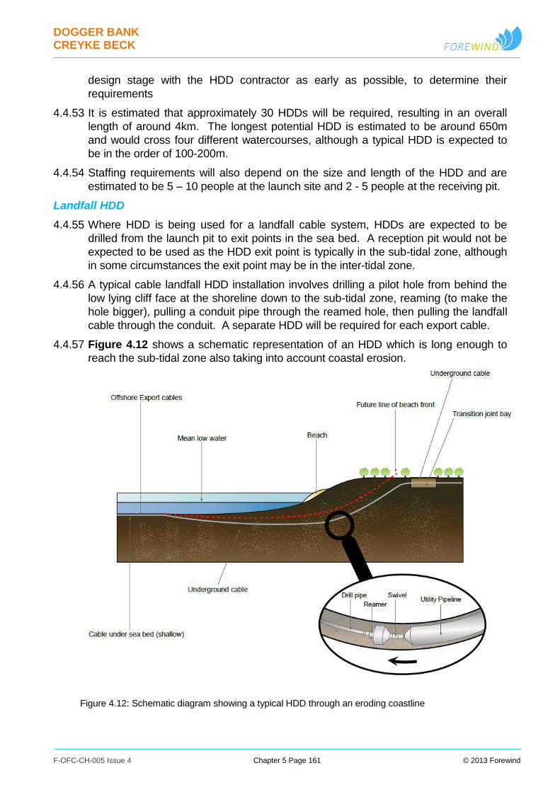
DOGGER BANK CREYKE BECK
F-OFC-CH-005 Issue 4 Chapter 5 Page 161 © 2013 Forewind
design stage with the HDD contractor as early as possible, to determine their
requirements
4.4.53 It is estimated that approximately 30 HDDs will be required, resulting in an overall
length of around 4km. The longest potential HDD is estimated to be around 650m
and would cross four different watercourses, although a typical HDD is expected to
be in the order of 100-200m.
4.4.54 Staffing requirements will also depend on the size and length of the HDD and are
estimated to be 5 – 10 people at the launch site and 2 - 5 people at the receiving pit.
Landfall HDD
4.4.55 Where HDD is being used for a landfall cable system, HDDs are expected to be
drilled from the launch pit to exit points in the sea bed. A reception pit would not be
expected to be used as the HDD exit point is typically in the sub-tidal zone, although
in some circumstances the exit point may be in the inter-tidal zone.
4.4.56 A typical cable landfall HDD installation involves drilling a pilot hole from behind the
low lying cliff face at the shoreline down to the sub-tidal zone, reaming (to make the
hole bigger), pulling a conduit pipe through the reamed hole, then pulling the landfall
cable through the conduit. A separate HDD will be required for each export cable.
4.4.57 Figure 4.12 shows a schematic representation of an HDD which is long enough to
reach the sub-tidal zone also taking into account coastal erosion.
Figure 4.12: Schematic diagram showing a typical HDD through an eroding coastline
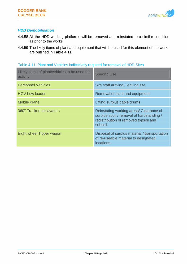
DOGGER BANK CREYKE BECK
F-OFC-CH-005 Issue 4 Chapter 5 Page 162 © 2013 Forewind
HDD Demobilisation
4.4.58 All the HDD working platforms will be removed and reinstated to a similar condition
as prior to the works.
4.4.59 The likely items of plant and equipment that will be used for this element of the works
are outlined in Table 4.11.
Table 4.11: Plant and Vehicles indicatively required for removal of HDD Sites
Likely items of plant/vehicles to be used for
activity Specific Use
Personnel Vehicles Site staff arriving / leaving site
HGV Low loader Removal of plant and equipment
Mobile crane Lifting surplus cable drums
360⁰ Tracked excavators Reinstating working areas/ Clearance of
surplus spoil / removal of hardstanding /
redistribution of removed topsoil and
subsoil.
Eight wheel Tipper wagon Disposal of surplus material / transportation
of re-useable material to designated
locations
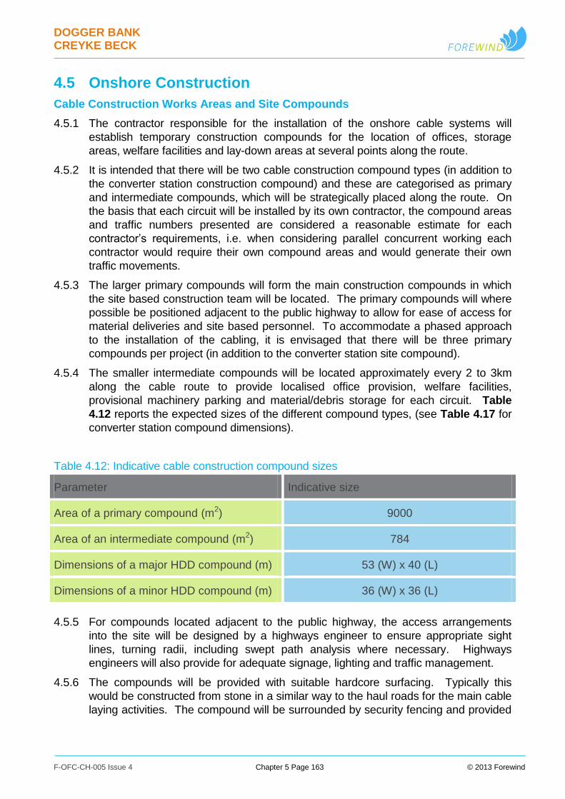
DOGGER BANK CREYKE BECK
F-OFC-CH-005 Issue 4 Chapter 5 Page 163 © 2013 Forewind
4.5 Onshore Construction
Cable Construction Works Areas and Site Compounds
4.5.1 The contractor responsible for the installation of the onshore cable systems will
establish temporary construction compounds for the location of offices, storage
areas, welfare facilities and lay-down areas at several points along the route.
4.5.2 It is intended that there will be two cable construction compound types (in addition to
the converter station construction compound) and these are categorised as primary
and intermediate compounds, which will be strategically placed along the route. On
the basis that each circuit will be installed by its own contractor, the compound areas
and traffic numbers presented are considered a reasonable estimate for each
contractor’s requirements, i.e. when considering parallel concurrent working each
contractor would require their own compound areas and would generate their own
traffic movements.
4.5.3 The larger primary compounds will form the main construction compounds in which
the site based construction team will be located. The primary compounds will where
possible be positioned adjacent to the public highway to allow for ease of access for
material deliveries and site based personnel. To accommodate a phased approach
to the installation of the cabling, it is envisaged that there will be three primary
compounds per project (in addition to the converter station site compound).
4.5.4 The smaller intermediate compounds will be located approximately every 2 to 3km
along the cable route to provide localised office provision, welfare facilities,
provisional machinery parking and material/debris storage for each circuit. Table
4.12 reports the expected sizes of the different compound types, (see Table 4.17 for
converter station compound dimensions).
Table 4.12: Indicative cable construction compound sizes
Parameter Indicative size
Area of a primary compound (m2) 9000
Area of an intermediate compound (m2) 784
Dimensions of a major HDD compound (m) 53 (W) x 40 (L)
Dimensions of a minor HDD compound (m) 36 (W) x 36 (L)
4.5.5 For compounds located adjacent to the public highway, the access arrangements
into the site will be designed by a highways engineer to ensure appropriate sight
lines, turning radii, including swept path analysis where necessary. Highways
engineers will also provide for adequate signage, lighting and traffic management.
4.5.6 The compounds will be provided with suitable hardcore surfacing. Typically this
would be constructed from stone in a similar way to the haul roads for the main cable
laying activities. The compound will be surrounded by security fencing and provided
DOGGER BANK CREYKE BECK
F-OFC-CH-005 Issue 4 Chapter 5 Page 164 © 2013 Forewind
with lockable gates to control access to the compound. Where necessary, suitable
site drainage will be provided to deal with surface water run-off from the compound.
4.5.7 For both practicality and health and safety reasons it is envisaged that both primary
and intermediate compounds will be lit during the works. The lighting will be switched
off during periods where the natural lighting levels are adequate. It is envisaged that
the lighting will be left on overnight for security purposes. Any compound lighting will
be designed to minimise light spillage.
4.5.8 The construction compounds will indicatively contain the following elements:
Site offices;
Welfare facilities;
A compound for storage of items like cable drums, ducting and other
construction materials (primary compound only);
General storage area;
Car parking area;
Plant storage area – Note: it is assumed that items of plant will be removed from
site when they require major maintenance work to be undertaken;
Storage containers;
Waste management area; and
A compound with bunded generator and fuel storage.
4.5.9 Indicative compound layout plans are provided for the primary and intermediate
compounds in Figure 4.13 and Figure 4.14 respectively.
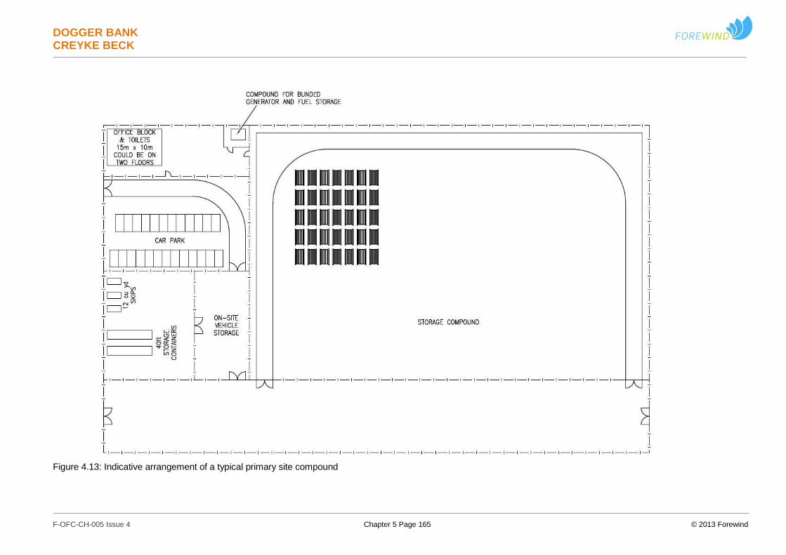
DOGGER BANK CREYKE BECK
F-OFC-CH-005 Issue 4 Chapter 5 Page 165 © 2013 Forewind
Figure 4.13: Indicative arrangement of a typical primary site compound

DOGGER BANK CREYKE BECK
F-OFC-CH-005 Issue 4 Chapter 5 Page 166 © 2013 Forewind
Figure 4.14: Indicative arrangement of a typical intermediate site compound
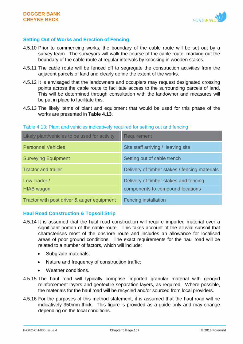
DOGGER BANK CREYKE BECK
F-OFC-CH-005 Issue 4 Chapter 5 Page 167 © 2013 Forewind
Setting Out of Works and Erection of Fencing
4.5.10 Prior to commencing works, the boundary of the cable route will be set out by a
survey team. The surveyors will walk the course of the cable route, marking out the
boundary of the cable route at regular intervals by knocking in wooden stakes.
4.5.11 The cable route will be fenced off to segregate the construction activities from the
adjacent parcels of land and clearly define the extent of the works.
4.5.12 It is envisaged that the landowners and occupiers may request designated crossing
points across the cable route to facilitate access to the surrounding parcels of land.
This will be determined through consultation with the landowner and measures will
be put in place to facilitate this.
4.5.13 The likely items of plant and equipment that would be used for this phase of the
works are presented in Table 4.13.
Table 4.13: Plant and vehicles indicatively required for setting out and fencing
Likely plant/vehicles to be used for activity Requirement
Personnel Vehicles Site staff arriving / leaving site
Surveying Equipment Setting out of cable trench
Tractor and trailer Delivery of timber stakes / fencing materials
Low loader /
HIAB wagon
Delivery of timber stakes and fencing
components to compound locations
Tractor with post driver & auger equipment Fencing installation
Haul Road Construction & Topsoil Strip
4.5.14 It is assumed that the haul road construction will require imported material over a
significant portion of the cable route. This takes account of the alluvial subsoil that
characterises most of the onshore route and includes an allowance for localised
areas of poor ground conditions. The exact requirements for the haul road will be
related to a number of factors, which will include:
Subgrade materials;
Nature and frequency of construction traffic;
Weather conditions.
4.5.15 The haul road will typically comprise imported granular material with geogrid
reinforcement layers and geotextile separation layers, as required. Where possible,
the materials for the haul road will be recycled and/or sourced from local providers.
4.5.16 For the purposes of this method statement, it is assumed that the haul road will be
indicatively 350mm thick. This figure is provided as a guide only and may change
depending on the local conditions.
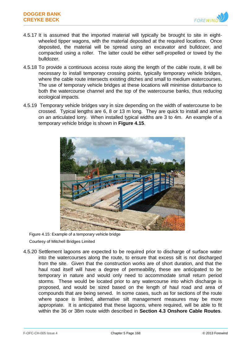
DOGGER BANK CREYKE BECK
F-OFC-CH-005 Issue 4 Chapter 5 Page 168 © 2013 Forewind
4.5.17 It is assumed that the imported material will typically be brought to site in eight-
wheeled tipper wagons, with the material deposited at the required locations. Once
deposited, the material will be spread using an excavator and bulldozer, and
compacted using a roller. The latter could be either self-propelled or towed by the
bulldozer.
4.5.18 To provide a continuous access route along the length of the cable route, it will be
necessary to install temporary crossing points, typically temporary vehicle bridges,
where the cable route intersects existing ditches and small to medium watercourses.
The use of temporary vehicle bridges at these locations will minimise disturbance to
both the watercourse channel and the top of the watercourse banks, thus reducing
ecological impacts.
4.5.19 Temporary vehicle bridges vary in size depending on the width of watercourse to be
crossed. Typical lengths are 6, 8 or 13 m long. They are quick to install and arrive
on an articulated lorry. When installed typical widths are 3 to 4m. An example of a
temporary vehicle bridge is shown in Figure 4.15.
Figure 4.15: Example of a temporary vehicle bridge
Courtesy of Mitchell Bridges Limited
4.5.20 Settlement lagoons are expected to be required prior to discharge of surface water
into the watercourses along the route, to ensure that excess silt is not discharged
from the site. Given that the construction works are of short duration, and that the
haul road itself will have a degree of permeability, these are anticipated to be
temporary in nature and would only need to accommodate small return period
storms. These would be located prior to any watercourse into which discharge is
proposed, and would be sized based on the length of haul road and area of
compounds that are being served. In some cases, such as for sections of the route
where space is limited, alternative silt management measures may be more
appropriate. It is anticipated that these lagoons, where required, will be able to fit
within the 36 or 38m route width described in Section 4.3 Onshore Cable Routes.

DOGGER BANK CREYKE BECK
F-OFC-CH-005 Issue 4 Chapter 5 Page 169 © 2013 Forewind
It is assumed that topsoil and subsoil storage areas can be locally adjusted to
accommodate the lagoons. The topsoil strip will be undertaken as part of the haul
road preparation using tracked excavators, dumpers and dozers. The topsoil will not
be stripped from beneath the topsoil storage areas.
4.5.21 During the preparation phase of the works, appropriate protection measures will be
put in place where overhead lines cross the cable route. The protection measures
will be in accordance with the Health & Safety Executive Guidance Note GS6
‘Avoidance of danger from overhead electric power lines’.
4.5.22 Furthermore, as part of the preparation phase, it will be necessary to remove
hedgerows/trees from within the cable route. There may be ecological requirements
that need to be addressed in association with this process and these will be
incorporated into the working method. See Chapter 25 Terrestrial Ecology for
further discussion.
4.5.23 To control dust during the summer months, it may be necessary to dampen down the
subsoil haul roads. This would be carried out using a water bowser. See Chapter
30 Air Quality and Chapter 23 Tourism and Recreation for further discussion.
4.5.24 Where the cable route intersects with a public right of way (PRoW), it will be
necessary to apply for either a temporary closure, use of traffic management, or
diversion through ERYC (East Riding of Yorkshire Council). Diversions and closure
works will need to be placed prior to construction works commencing.
4.5.25 Mud and debris affecting local highways will be controlled by means of a wheel wash
and/or road sweeper. See also Chapter 23 Tourism and Recreation for further
details.
4.5.26 The likely items of plant and equipment that would be used for this element of the
works are presented in Table 4.14.

DOGGER BANK CREYKE BECK
F-OFC-CH-005 Issue 4 Chapter 5 Page 170 © 2013 Forewind
Table 4.14: Plant and vehicles indicatively required for haul road construction and top-soil strip
Likely items of plant/vehicles to be used for
activity Specific Use
Personnel Vehicles Site staff arriving / leaving site
Low loader /
HIAB wagon
Delivery of geotextiles/geogrid/pipes
for haul road construction
Eight wheel Tipper wagon Delivery of hardcore for haul road
construction
360⁰ Tracked/wheeled excavators Distributing hardcore material and topsoil
strip
Bulldozer Distributing hardcore material and topsoil
strip
Roller Compacting haul road
Dumper (5t) Distributing ancillary items
Wheel wash Cleaning outgoing vehicles
Road sweeper Cleaning local roads
Cable Delivery, Storage and Installation
4.5.27 The cable drums, similar to the one shown in Figure 4.16, will be initially delivered to
the primary or intermediate compound locations on a HGV low loader and will be
lifted off the low loader and deposited within the cable storage area, using a mobile
crane.
4.5.28 From the laydown areas of the construction compounds the cable drums will be
brought to the joint bay locations. Individual cable drums will be lifted onto a cable
drum trailer which will be towed by a tractor unit to the intended joint bay. A cable
winch will be set up at the following joint bay position.
4.5.29 The joint bay will be located along the route at intervals compatible with the cable
section length. Where present the duct ends will be exposed within the joint-bays.
4.5.30 The joint bays are expected to be approximately 10m long x 4m wide and will require
temporary earthwork support, in a similar fashion to the trenches. The joint bays will
require a concrete base with drainage canals and will need to be kept free of water
and debris during the cable installation works.
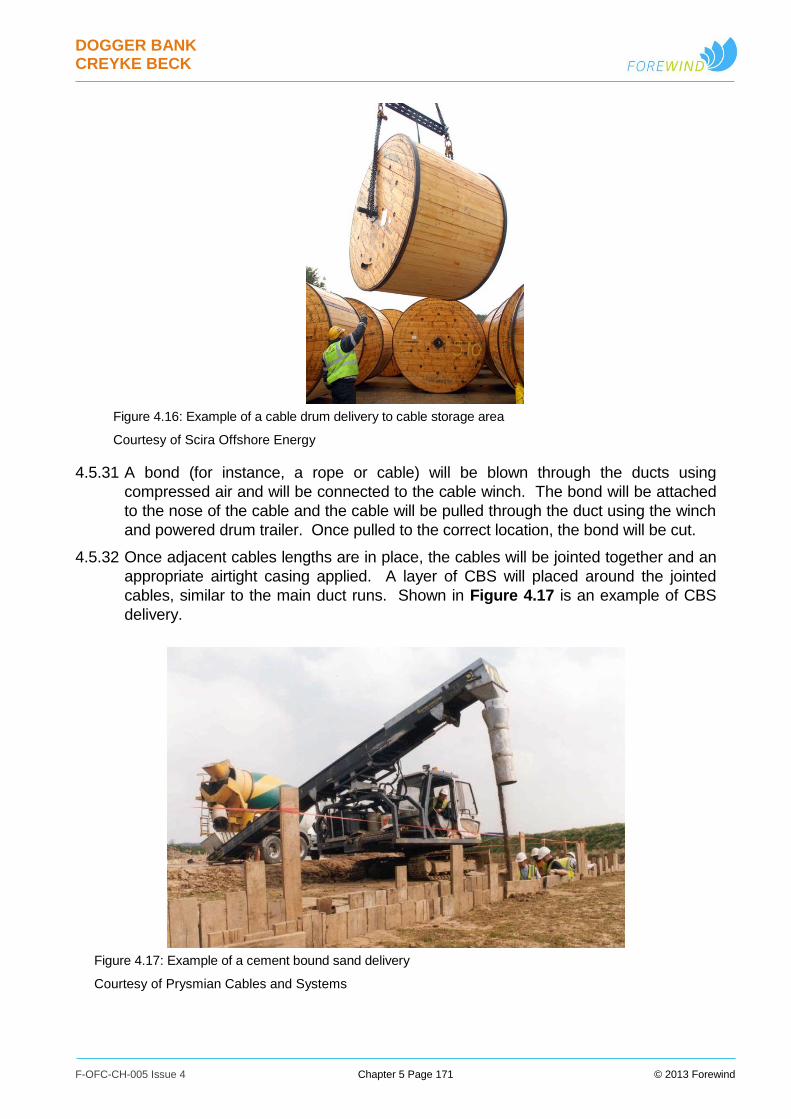
DOGGER BANK CREYKE BECK
F-OFC-CH-005 Issue 4 Chapter 5 Page 171 © 2013 Forewind
Figure 4.16: Example of a cable drum delivery to cable storage area
Courtesy of Scira Offshore Energy
4.5.31 A bond (for instance, a rope or cable) will be blown through the ducts using
compressed air and will be connected to the cable winch. The bond will be attached
to the nose of the cable and the cable will be pulled through the duct using the winch
and powered drum trailer. Once pulled to the correct location, the bond will be cut.
4.5.32 Once adjacent cables lengths are in place, the cables will be jointed together and an
appropriate airtight casing applied. A layer of CBS will placed around the jointed
cables, similar to the main duct runs. Shown in Figure 4.17 is an example of CBS
delivery.
Figure 4.17: Example of a cement bound sand delivery
Courtesy of Prysmian Cables and Systems
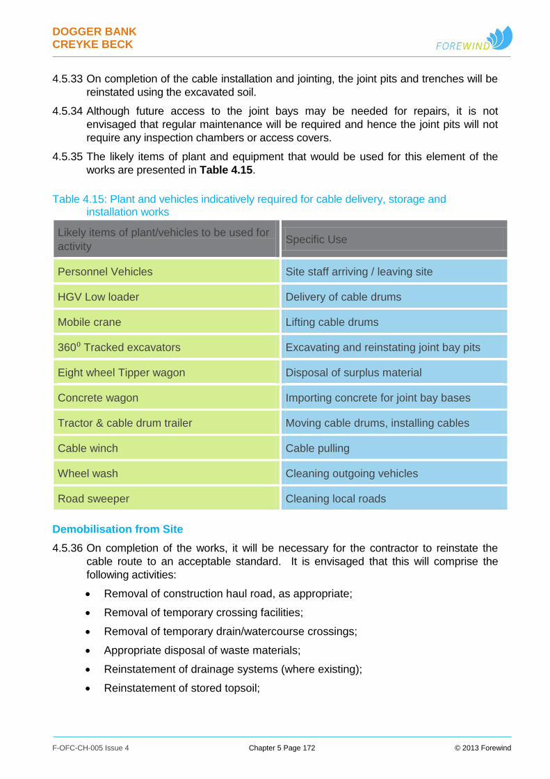
DOGGER BANK CREYKE BECK
F-OFC-CH-005 Issue 4 Chapter 5 Page 172 © 2013 Forewind
4.5.33 On completion of the cable installation and jointing, the joint pits and trenches will be
reinstated using the excavated soil.
4.5.34 Although future access to the joint bays may be needed for repairs, it is not
envisaged that regular maintenance will be required and hence the joint pits will not
require any inspection chambers or access covers.
4.5.35 The likely items of plant and equipment that would be used for this element of the
works are presented in Table 4.15.
Table 4.15: Plant and vehicles indicatively required for cable delivery, storage and installation works
Likely items of plant/vehicles to be used for
activity Specific Use
Personnel Vehicles Site staff arriving / leaving site
HGV Low loader Delivery of cable drums
Mobile crane Lifting cable drums
360⁰ Tracked excavators Excavating and reinstating joint bay pits
Eight wheel Tipper wagon Disposal of surplus material
Concrete wagon Importing concrete for joint bay bases
Tractor & cable drum trailer Moving cable drums, installing cables
Cable winch Cable pulling
Wheel wash Cleaning outgoing vehicles
Road sweeper Cleaning local roads
Demobilisation from Site
4.5.36 On completion of the works, it will be necessary for the contractor to reinstate the
cable route to an acceptable standard. It is envisaged that this will comprise the
following activities:
Removal of construction haul road, as appropriate;
Removal of temporary crossing facilities;
Removal of temporary drain/watercourse crossings;
Appropriate disposal of waste materials;
Reinstatement of drainage systems (where existing);
Reinstatement of stored topsoil;
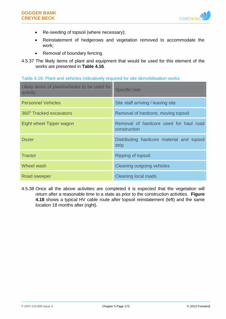
DOGGER BANK CREYKE BECK
F-OFC-CH-005 Issue 4 Chapter 5 Page 173 © 2013 Forewind
Re-seeding of topsoil (where necessary);
Reinstatement of hedgerows and vegetation removed to accommodate the
work;
Removal of boundary fencing.
4.5.37 The likely items of plant and equipment that would be used for this element of the
works are presented in Table 4.16.
Table 4.16: Plant and vehicles indicatively required for site demobilisation works
Likely items of plant/vehicles to be used for
activity Specific Use
Personnel Vehicles Site staff arriving / leaving site
360⁰ Tracked excavators Removal of hardcore, moving topsoil
Eight wheel Tipper wagon Removal of hardcore used for haul road
construction
Dozer Distributing hardcore material and topsoil
strip
Tractor Ripping of topsoil
Wheel wash Cleaning outgoing vehicles
Road sweeper Cleaning local roads
4.5.38 Once all the above activities are completed it is expected that the vegetation will
return after a reasonable time to a state as prior to the construction activities. Figure
4.18 shows a typical HV cable route after topsoil reinstatement (left) and the same
location 18 months after (right).

DOGGER BANK CREYKE BECK
F-OFC-CH-005 Issue 4 Chapter 5 Page 174 © 2013 Forewind
Figure 4.18: Example of cable installation swathe after topsoil reinstatement
Courtesy of Prysmian Cables and Systems
4.6 Onshore Converter Station
4.6.1 Two converter stations will be built, one for each of the Creyke Beck projects. Each
converter station will be rated at up to around 1,000MW nominal power.
4.6.2 The two converter stations will be built on farmland to the south of Beverley. The site
is located on the northern side of the A1079, at about 1.5km to the south-east of the
intersection with the A164. The converter stations site is located at about 1km to the
north of the existing National Grid substation at Creyke Beck.
Converter Station Details
Figure 4.19: Typical converter station layout
Courtesy of Siemens
DOGGER BANK CREYKE BECK
F-OFC-CH-005 Issue 4 Chapter 5 Page 175 © 2013 Forewind
4.6.3 Access to the site for construction traffic will be via a new access road off a lay-by on
the north of the A1079. This will be closed once the site is operational and only
opened to allow access to heavy loads if large equipment has to be replaced. This
should be a very infrequent requirement and in the operational phase of the
substation, traffic will access and egress the site via local roads.
4.6.4 Each converter station will include:
A valve hall, which is a large building that houses electronic devices that convert
the power from DC to AC.
Ancillary buildings which may containing:
A control room and operator facilities;
Communication equipment and an interface with the National Grid Control
Centre;
An auxiliary transformer to provide low voltage electrical power for the
converter station;
Ancillary equipment such as measurement, protection and metering
equipment; and
Equipment storerooms.
Outdoor equipment areas containing rigid aluminium DC and AC current
connectors, transformers, cable sealing ends and air-conditioning equipment.
Permanent lighting, designed to minimise glare and light spillage off-site, to the
sky and to adjacent areas (particularly residential properties close to the site);
Areas for car parking and internal roads.
4.6.5 An illustrative example of a typical converter substation similar to those proposed for
Creyke Beck A &and B is shown in Figure 4.19.
4.6.6 The valve halls are expected to be steel framed buildings with cladding. The colour
and external materials will be agreed with the local authority. The onshore converter
stations will be provided with lightning protection systems (LPS).
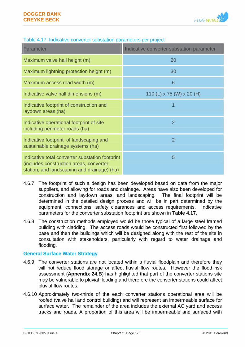
DOGGER BANK CREYKE BECK
F-OFC-CH-005 Issue 4 Chapter 5 Page 176 © 2013 Forewind
Table 4.17: Indicative converter substation parameters per project
Parameter Indicative converter substation parameter
Maximum valve hall height (m) 20
Maximum lightning protection height (m) 30
Maximum access road width (m) 6
Indicative valve hall dimensions (m) 110 (L) x 75 (W) x 20 (H)
Indicative footprint of construction and
laydown areas (ha)
1
Indicative operational footprint of site
including perimeter roads (ha)
2
Indicative footprint of landscaping and
sustainable drainage systems (ha)
2
Indicative total converter substation footprint
(includes construction areas, converter
station, and landscaping and drainage) (ha)
5
4.6.7 The footprint of such a design has been developed based on data from the major
suppliers, and allowing for roads and drainage. Areas have also been developed for
construction and laydown areas, and landscaping. The final footprint will be
determined in the detailed design process and will be in part determined by the
equipment, connections, safety clearances and access requirements. Indicative
parameters for the converter substation footprint are shown in Table 4.17.
4.6.8 The construction methods employed would be those typical of a large steel framed
building with cladding. The access roads would be constructed first followed by the
base and then the buildings which will be designed along with the rest of the site in
consultation with stakeholders, particularly with regard to water drainage and
flooding.
General Surface Water Strategy
4.6.9 The converter stations are not located within a fluvial floodplain and therefore they
will not reduce flood storage or affect fluvial flow routes. However the flood risk
assessment (Appendix 24.B) has highlighted that part of the converter stations site
may be vulnerable to pluvial flooding and therefore the converter stations could affect
pluvial flow routes.
4.6.10 Approximately two-thirds of the each converter stations operational area will be
roofed (valve hall and control building) and will represent an impermeable surface for
surface water. The remainder of the area includes the external AC yard and access
tracks and roads. A proportion of this area will be impermeable and surfaced with
DOGGER BANK CREYKE BECK
F-OFC-CH-005 Issue 4 Chapter 5 Page 177 © 2013 Forewind
gravel where not supporting structural foundations. The current land use is
agricultural grassland, therefore, the converter stations site will result in an increase
in impermeable area compared to current use at the site. As such any consequent
increase in run-off will have to be mitigated to ensure there is no increase in flood risk
elsewhere.
4.6.11 In order to manage the surface water run-off from the converter stations, an
adequate drainage system will be required. The surface water attenuation will be
sized for at least the 1 in 100 storm event plus an allowance of 30% for climate
change. Storage of the surface water either above or below ground through
attenuation is required prior to discharge at a restricted rate. An allowable discharge
rate of 1.4litres/second/hectare (l/s/h) is proposed based on best practice.
4.6.12 Based on the proposed allowable discharge rate of 1.4l/s/ha and the impermeable
area of the converter stations the following surface water storage calculations identify
the volumes which will be required to be attenuated on site, based on different rainfall
events for this part of the UK:
1 in 30 year event – between 1300m3 and 1800m3;
1 in 100 year event – between 1700m3 and 2300m3; and
1 in 100 year + 30% CC – between 2400m3 and 3200m3.
4.6.13 A suitable drainage system will be developed with sufficient volume to attenuate the 1
in 100 year (plus climate change) volumes.
4.6.14 Different forms of sustainable drainage techniques (SuDS) can be used to treat
runoff, including permeable paving, swales and detention basins. Forewind are
planning the use of swales, together with an oil separator system, as the preferred
approach to treatment of run-off. Rainwater ‘harvesting’ (for use on-site) will be
investigated. As there is no mains sewer connection available in the vicinity foul
water waste is expected to be treated by a packaged treatment plant (PTP)
installation, with the PTP discharge going to the planned swales. In turn, the swales
are expected to discharge into an ‘attenuation’ area, planted with meadow grass and
scrub surround, and then into an adjacent drainage ditch.
4.6.15 The proposed approach to drainage will be sustainable and support biodiversity
enhancement/ ecological mitigation efforts.
4.6.16 As the detailed design progresses, the Environment Agency, Yorkshire Water, and
East Riding of Yorkshire Council will be fully consulted to ensure their approval of the
final design. This is discussed further in Chapter 24 Geology, Water Resources
and Land Quality.

DOGGER BANK CREYKE BECK
F-OFC-CH-005 Issue 4 Chapter 5 Page 178 © 2013 Forewind
4.7 Expected Construction Traffic
4.7.1 The construction activities will generate HGV construction traffic that will add to the
existing ordinary traffic affecting the access roads in the proximity of the works.
Construction traffic access options have been selected to avoid smaller local roads
and built up areas, as discussed in detail within Chapter 28 Traffic and Access.
4.7.2 For the cable routes a worst case scenario based on parallel, independent installation
of the two projects has been considered. Deliveries for the cable route include the
following elements:
Haul road hard core material;
Cable drums and cable joints;
Tiles, ducts and fibre-optic ducts;
Trench excavation material.
4.7.3 It is assumed that the deliveries will be carried out with 20t dumper trucks. One HGV
delivery corresponds to a two way HGV movement along the affected road.
4.7.4 Table 4.18 reports the key results of the traffic assessment carried out. The figures
are given in terms of total number of deliveries per project.
Table 4.18: Indicative number of deliveries expected for the onshore works
Construction activity Indicative HGV number of deliveries per
project
HVDC cable route per project
(independent installation)
9,300
HVAC cable route per project
(independent installation)
490
Primary compounds (per project) 1,600
Intermediate compounds (per project) 500
Converter station (per project) 6,060
4.7.5 Chapter 28 Traffic and Access contains more detailed information on the traffic and
access requirements for the onshore converter station.

DOGGER BANK CREYKE BECK
F-OFC-CH-005 Issue 4 Chapter 5 Page 179 © 2013 Forewind
5 Offshore Project Layouts
5.1 Wind Farm Layouts
5.1.1 The final chosen layout of the wind turbines, and other wind farm components, will
depend on a number of factors including: stakeholder feedback, seabed obstructions,
ground conditions, water depth, economic factors, and the chosen wind turbine.
5.1.2 Areas where flexibility is required include, but are not limited to, the following:
Total number of wind turbines (subject to the maximum 1,200MW installed
generating capacity limit);
Location and pattern of wind turbines within the array areas;
Capacity and type of wind turbines (in line with the options defined within the
wind turbine envelope) and their mix in the development;
Extent to which the consented areas are developed – in part or in full;
Mix of, and areas used for, different foundation types within the array areas;
Variation of detailed design within any of the identified foundation types;
Numbers and positions of offshore platforms, met masts, and mooring buoys;
Number and routing of subsea cables (and thus number of onshore cables and
transition bays);
The points where cables and pipelines (including existing infrastructure and
other wind farm components) are crossed; and
The need to microsite the location of any structures by up to 50m during
construction.
5.1.3 To ensure sufficient flexibility of the scheme design can be maintained, all wind
turbine layouts included in the body of this ES or its Appendices are purely illustrative
and are solely for the purpose of informing the reader as to the fundamental flexibility
permitted. No layout provided represents a final project layout, over and above other
potential permutations. The final layout will be designed within the parameters
assessed and will comply with the relevant limitations, requirements and conditions in
the draft Development Consent Order (DCO).
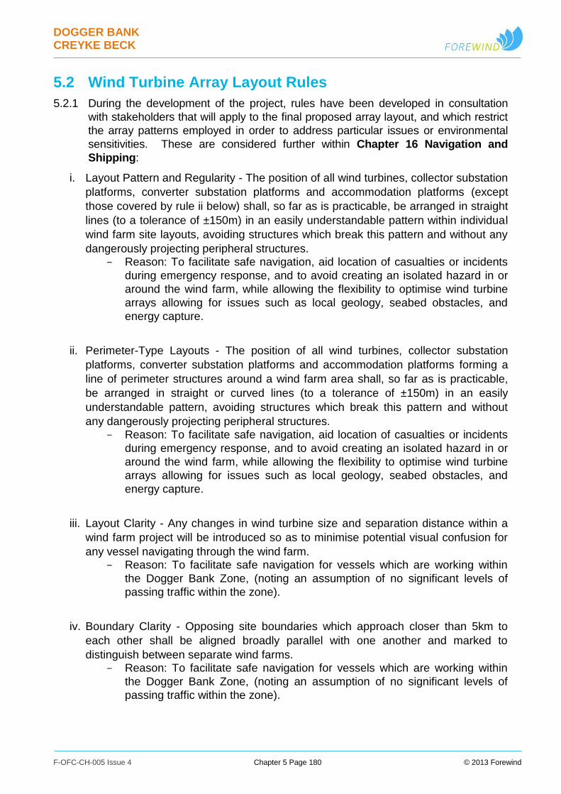
DOGGER BANK CREYKE BECK
F-OFC-CH-005 Issue 4 Chapter 5 Page 180 © 2013 Forewind
5.2 Wind Turbine Array Layout Rules
5.2.1 During the development of the project, rules have been developed in consultation
with stakeholders that will apply to the final proposed array layout, and which restrict
the array patterns employed in order to address particular issues or environmental
sensitivities. These are considered further within Chapter 16 Navigation and
Shipping:
i. Layout Pattern and Regularity - The position of all wind turbines, collector substation
platforms, converter substation platforms and accommodation platforms (except
those covered by rule ii below) shall, so far as is practicable, be arranged in straight
lines (to a tolerance of ±150m) in an easily understandable pattern within individual
wind farm site layouts, avoiding structures which break this pattern and without any
dangerously projecting peripheral structures. Reason: To facilitate safe navigation, aid location of casualties or incidents
during emergency response, and to avoid creating an isolated hazard in or
around the wind farm, while allowing the flexibility to optimise wind turbine
arrays allowing for issues such as local geology, seabed obstacles, and
energy capture.
ii. Perimeter-Type Layouts - The position of all wind turbines, collector substation
platforms, converter substation platforms and accommodation platforms forming a
line of perimeter structures around a wind farm area shall, so far as is practicable,
be arranged in straight or curved lines (to a tolerance of ±150m) in an easily
understandable pattern, avoiding structures which break this pattern and without
any dangerously projecting peripheral structures. Reason: To facilitate safe navigation, aid location of casualties or incidents
during emergency response, and to avoid creating an isolated hazard in or
around the wind farm, while allowing the flexibility to optimise wind turbine
arrays allowing for issues such as local geology, seabed obstacles, and
energy capture.
iii. Layout Clarity - Any changes in wind turbine size and separation distance within a
wind farm project will be introduced so as to minimise potential visual confusion for
any vessel navigating through the wind farm. Reason: To facilitate safe navigation for vessels which are working within
the Dogger Bank Zone, (noting an assumption of no significant levels of
passing traffic within the zone).
iv. Boundary Clarity - Opposing site boundaries which approach closer than 5km to
each other shall be aligned broadly parallel with one another and marked to
distinguish between separate wind farms. Reason: To facilitate safe navigation for vessels which are working within
the Dogger Bank Zone, (noting an assumption of no significant levels of
passing traffic within the zone).
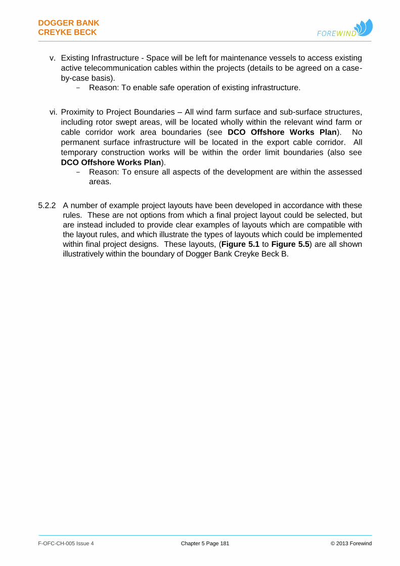
DOGGER BANK CREYKE BECK
F-OFC-CH-005 Issue 4 Chapter 5 Page 181 © 2013 Forewind
v. Existing Infrastructure - Space will be left for maintenance vessels to access existing
active telecommunication cables within the projects (details to be agreed on a case-
by-case basis). Reason: To enable safe operation of existing infrastructure.
vi. Proximity to Project Boundaries – All wind farm surface and sub-surface structures,
including rotor swept areas, will be located wholly within the relevant wind farm or
cable corridor work area boundaries (see DCO Offshore Works Plan). No
permanent surface infrastructure will be located in the export cable corridor. All
temporary construction works will be within the order limit boundaries (also see
DCO Offshore Works Plan). Reason: To ensure all aspects of the development are within the assessed
areas.
5.2.2 A number of example project layouts have been developed in accordance with these
rules. These are not options from which a final project layout could be selected, but
are instead included to provide clear examples of layouts which are compatible with
the layout rules, and which illustrate the types of layouts which could be implemented
within final project designs. These layouts, (Figure 5.1 to Figure 5.5) are all shown
illustratively within the boundary of Dogger Bank Creyke Beck B.

DOGGER BANK CREYKE BECK
F-OFC-CH-005 Issue 4 Chapter 5 Page 182 © 2013 Forewind
Figure 5.1: Illustrative Layout 1 - Perimeter plus regular grid
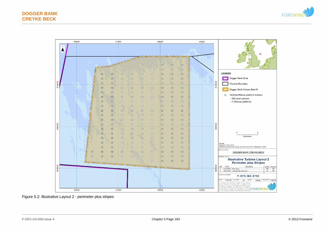
DOGGER BANK CREYKE BECK
F-OFC-CH-005 Issue 4 Chapter 5 Page 183 © 2013 Forewind
Figure 5.2: Illustrative Layout 2 - perimeter plus stripes
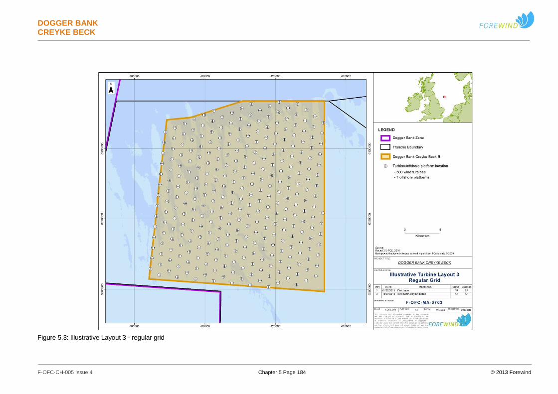
DOGGER BANK CREYKE BECK
F-OFC-CH-005 Issue 4 Chapter 5 Page 184 © 2013 Forewind
Figure 5.3: Illustrative Layout 3 - regular grid

DOGGER BANK CREYKE BECK
F-OFC-CH-005 Issue 4 Chapter 5 Page 185 © 2013 Forewind
Figure 5.4: Illustrative Layout 4 – reduced area regular grid
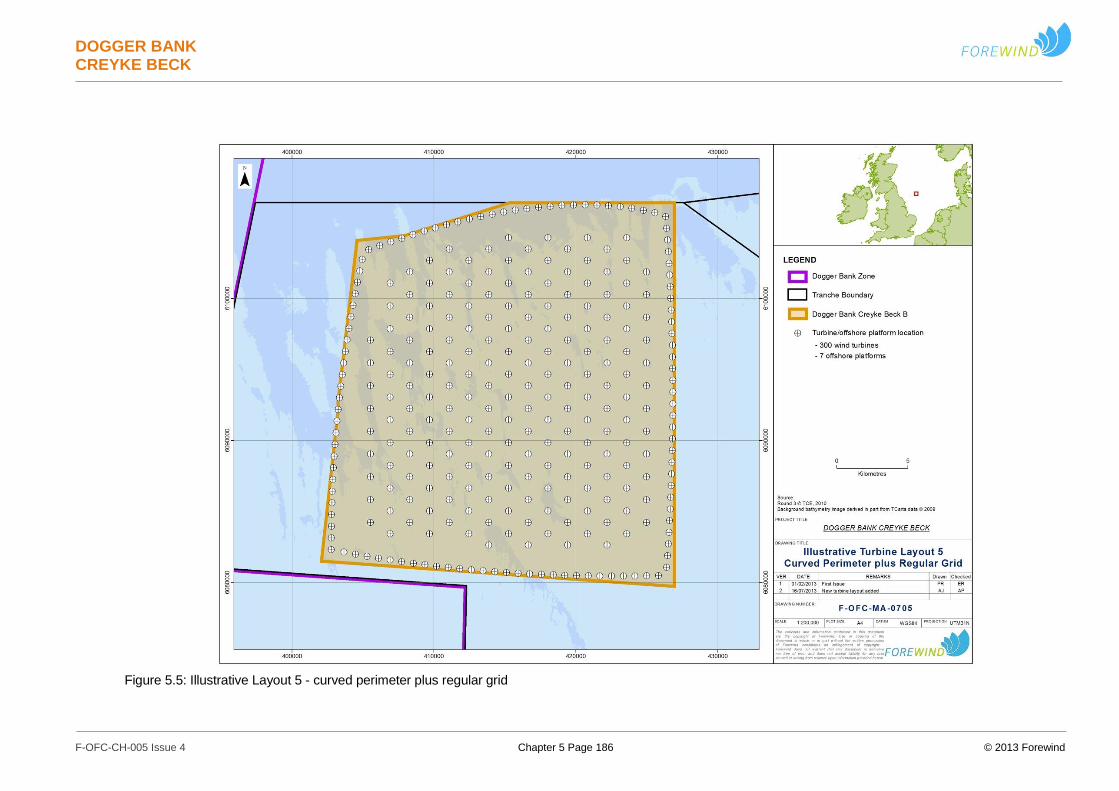
DOGGER BANK CREYKE BECK
F-OFC-CH-005 Issue 4 Chapter 5 Page 186 © 2013 Forewind
Figure 5.5: Illustrative Layout 5 - curved perimeter plus regular grid
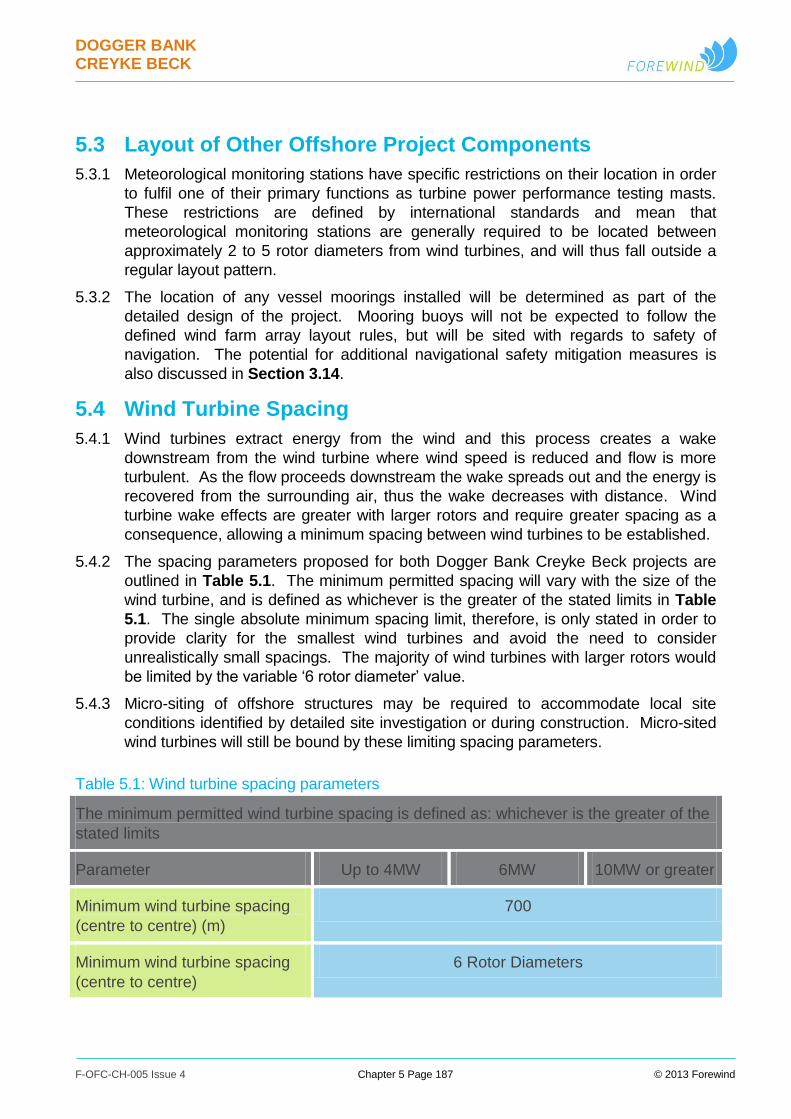
DOGGER BANK CREYKE BECK
F-OFC-CH-005 Issue 4 Chapter 5 Page 187 © 2013 Forewind
5.3 Layout of Other Offshore Project Components
5.3.1 Meteorological monitoring stations have specific restrictions on their location in order
to fulfil one of their primary functions as turbine power performance testing masts.
These restrictions are defined by international standards and mean that
meteorological monitoring stations are generally required to be located between
approximately 2 to 5 rotor diameters from wind turbines, and will thus fall outside a
regular layout pattern.
5.3.2 The location of any vessel moorings installed will be determined as part of the
detailed design of the project. Mooring buoys will not be expected to follow the
defined wind farm array layout rules, but will be sited with regards to safety of
navigation. The potential for additional navigational safety mitigation measures is
also discussed in Section 3.14.
5.4 Wind Turbine Spacing
5.4.1 Wind turbines extract energy from the wind and this process creates a wake
downstream from the wind turbine where wind speed is reduced and flow is more
turbulent. As the flow proceeds downstream the wake spreads out and the energy is
recovered from the surrounding air, thus the wake decreases with distance. Wind
turbine wake effects are greater with larger rotors and require greater spacing as a
consequence, allowing a minimum spacing between wind turbines to be established.
5.4.2 The spacing parameters proposed for both Dogger Bank Creyke Beck projects are
outlined in Table 5.1. The minimum permitted spacing will vary with the size of the
wind turbine, and is defined as whichever is the greater of the stated limits in Table
5.1. The single absolute minimum spacing limit, therefore, is only stated in order to
provide clarity for the smallest wind turbines and avoid the need to consider
unrealistically small spacings. The majority of wind turbines with larger rotors would
be limited by the variable ‘6 rotor diameter’ value.
5.4.3 Micro-siting of offshore structures may be required to accommodate local site
conditions identified by detailed site investigation or during construction. Micro-sited
wind turbines will still be bound by these limiting spacing parameters.
Table 5.1: Wind turbine spacing parameters
The minimum permitted wind turbine spacing is defined as: whichever is the greater of the
stated limits
Parameter Up to 4MW 6MW 10MW or greater
Minimum wind turbine spacing
(centre to centre) (m)
700
Minimum wind turbine spacing
(centre to centre)
6 Rotor Diameters
DOGGER BANK CREYKE BECK
F-OFC-CH-005 Issue 4 Chapter 5 Page 188 © 2013 Forewind
5.5 Proximity to Existing Infrastructure
Offshore Infrastructure
5.5.1 Several operational subsea pipelines and cables exist within the vicinity of the
Dogger Bank Creyke Beck projects. These existing structures have on-going
maintenance requirements and require certain minimum separation distances from
new wind farm structures to avoid mutual interference. There is also a need to
maintain separation between existing infrastructure and intrusive seabed activities,
such as anchoring and cable installation, to minimise the risk of damage.
5.5.2 Appropriate minimum separation distances have been developed by Forewind, and
are outlined in Table 5.2. Any cables or intrusive works required within the distances
proposed in Table 5.2 would be assumed to require detailed crossing or proximity
agreements with the owners of the infrastructure. These separation distances will be
discussed during consultation with the operators of relevant existing infrastructure,
and appropriate crossing or proximity agreements developed to enable coexistence.
The final agreed separation distances may vary from these minimum values on a
case-by-case basis. Further discussion of this subject is included within Chapter 17
Other Marine Users.
5.5.3 Crossings of cables and pipelines by Dogger Bank Creyke Beck cables will be
required, and the technical aspects are discussed within Section 3.11 Offshore
Cable & Pipeline Crossings. The commercial aspects will be addressed via
detailed discussions with the owners of the infrastructure to develop crossing
agreements which cover all necessary aspects of the operations.
5.14 Out-of-service telecommunications cables also exist within and near the zone, and
operational cables and pipelines could become out of service at short notice. Where
necessary, agreements would always be sought from the cable owners and it is
assumed at this early stage that suitable crossing or proximity agreements would
also be developed with the owners of out-of-service infrastructure. It is expected that
out-of-service infrastructure may be removed where necessary, as discussed in
Section 3.9 Offshore Cable Installation and Removal, where it cannot be avoided
by wind farm structures and activities.
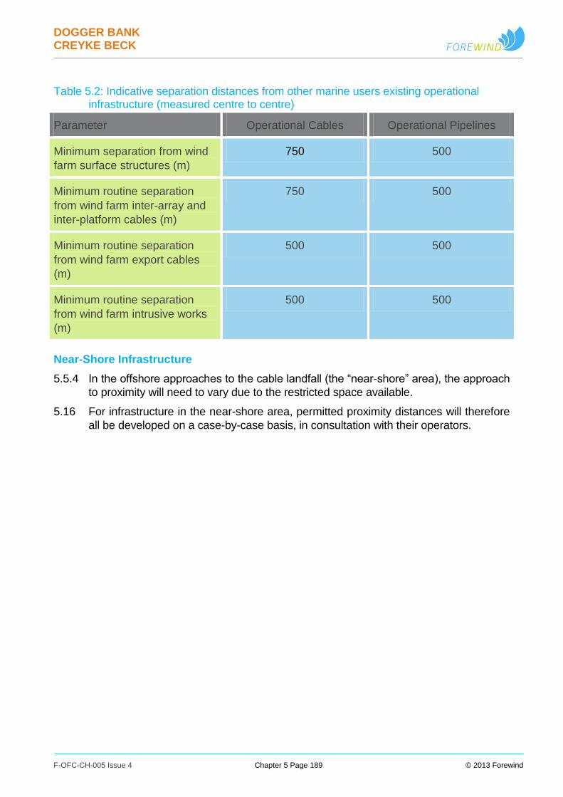
DOGGER BANK CREYKE BECK
F-OFC-CH-005 Issue 4 Chapter 5 Page 189 © 2013 Forewind
Table 5.2: Indicative separation distances from other marine users existing operational infrastructure (measured centre to centre)
Parameter Operational Cables Operational Pipelines
Minimum separation from wind
farm surface structures (m)
750 500
Minimum routine separation
from wind farm inter-array and
inter-platform cables (m)
750 500
Minimum routine separation
from wind farm export cables
(m)
500 500
Minimum routine separation
from wind farm intrusive works
(m)
500 500
Near-Shore Infrastructure
5.5.4 In the offshore approaches to the cable landfall (the “near-shore” area), the approach
to proximity will need to vary due to the restricted space available.
5.16 For infrastructure in the near-shore area, permitted proximity distances will therefore
all be developed on a case-by-case basis, in consultation with their operators.
DOGGER BANK CREYKE BECK
F-OFC-CH-005 Issue 4 Chapter 5 Page 190 © 2013 Forewind
6 Project Life Cycle
6.1.1 After consent for Dogger Bank Creyke Beck is granted, the projects would then
progress through a lifecycle described within the following sections.
6.2 Pre-Construction Engineering Surveys
6.2.1 The engineering surveys described in this section aim at assessing the feasibility of
the installation and assist the production of detailed designs and installation
procedures. These will be carried out in conjunction with all the required health and
safety, environmental, archaeological and ecology surveys.
6.2.2 It is noted that the final designs of the project, following the results of these pre-
construction surveys and subsequent detailed design activities, will be subject to final
approval under the terms of the DCO.
Offshore Pre-Construction
6.2.3 Before the start of offshore construction, a number of pre-construction surveys and
other activities will be required. These may include:
Further detailed geophysical surveys focussed on the actual locations of the
projects’ structures and cables, to understand in detail the seabed within the
wind farm and export cable corridor areas. Sidescan sonar, multibeam
echosounder, and magnetometry equipment are likely to be used in order to
input into areas such as detailed design, installation planning, and Unexploded
Ordnance (UXO) assessments;
Detailed geotechnical survey campaigns may also be undertaken to assist in
the design and siting of the wind farm structures. Boreholes, cone penetration
tests, vibrocores, and cable plough trials may be undertaken to understand the
shallow geology of each proposed structure site; and
Additional survey activities may also be required including Remotely Operated
Vehicle (ROV) or diver inspections of cable routes and identified seabed
anomalies. Cable route clearance activities may also be undertaken as
required, such as pre-lay grapnel runs.
Onshore Pre-Construction
6.2.4 Before the start of onshore construction, a number of pre-construction engineering
surveys and other activities will be required. These may include:
Geophysical surveys to understand in detail the conditions in the cable routes
and converter station areas; and
Geotechnical surveys to assist in the design, construction, and positioning of the
cable route, the horizontal directional drills and the converter stations.
Boreholes, cone penetration tests, and vibrocores, may be undertaken to
understand the geology of the proposed structure sites.

DOGGER BANK CREYKE BECK
F-OFC-CH-005 Issue 4 Chapter 5 Page 191 © 2013 Forewind
6.3 Construction
Construction Programme & Timing
6.3.1 Flexibility is required in the construction programme in order to accommodate a
range of uncertainties. These include the time taken to undertake procurement
activities and reach a financial investment decision, variable lead times for
components and equipment, and variable task durations dependent on the suppliers,
technologies and methodologies selected. This may be affected by factors such as
supply chain bottlenecks and the number and size of turbines selected.
6.3.2 The key permutations with regards to the programme and timetable for the
construction of Dogger Bank Creyke Beck include:
Construction of each of the Dogger Bank Creyke Beck projects may take place
continuously or in phases, within a specified duration.
Construction start may only occur within a specified time period after consent is
achieved.
If constructed at different times, either project may be first.
The timescales for construction of Dogger Bank Creyke Beck A and Dogger
Bank Creyke Beck B are not linked, except that there is a maximum gap
between the two projects with no onshore construction.
The first of the projects to be constructed may carry out onshore enabling works
for the second project, in order to reduce overall construction effort.
6.3.3 A number of fundamental construction programme parameters have been developed
to describe these options, and these are detailed within Table 6.1.

DOGGER BANK CREYKE BECK
F-OFC-CH-005 Issue 4 Chapter 5 Page 192 © 2013 Forewind
Table 6.1: Indicative construction programme parameters, per project
Parameter Creyke Beck A Creyke Beck B
Earliest construction start
onshore
At consent award (subject
to discharge of DCO
conditions)
At consent award (subject
to discharge of DCO
conditions)
Earliest construction start
offshore
18 months after consent
award
18 months after consent
award
Latest construction start
onshore
7 years after consent
award
7 years after consent
award
Latest construction start
offshore
7 years after consent
award
7 years after consent
award
Likely construction duration
onshore
18-36 months 18-36 months
Likely construction duration
offshore
3-6 years 3-6 years
Maximum onshore
construction gap between the
two projects (from first onshore
construction finish to second
onshore construction start)
5 years 5 years
Latest construction finish
onshore
10 years after consent
award
10 years after consent
award
Latest construction finish
offshore
13 years after consent
award
13 years after consent
award
6.3.4 Based on these programme options it can be seen that the Dogger Bank Creyke
Beck projects could be built in line with the following overarching scenarios:
Parallel – Build Dogger Bank Creyke Beck projects A and B together.
Sequential – Construction of one project commences after the start of the other.
This may result in projects overlapping, occurring in series or having a gap
between projects.
Enabling – Partial installation of some onshore elements for the second project
takes place while constructing the first project.

DOGGER BANK CREYKE BECK
F-OFC-CH-005 Issue 4 Chapter 5 Page 193 © 2013 Forewind
Onshore Construction
6.3.5 In order to better describe the onshore construction options, additional detail has
been developed in line with the overarching installation scenarios identified. The
timescales provided are indicative of what could conservatively be achieved in
normal circumstances, but do not reflect all possible eventualities which could arise
such as major supply chain issues, weather delays, etc.
HVDC Cables
6.3.6 The overarching construction scenarios and the construction durations applicable to
each are summarised in Table 6.2.
Table 6.2: Onshore HVDC cable construction options
Scenario Overview First Construction Phase Gap Second Construction Phase
Single 1 project Build one haul road
Dig 1 trench
Lay cables (in one trench)
Re-instate width
Time = up to 24 months
n/a n/a
Parallel 2 projects
in parallel
Build two haul roads
Dig two trenches
Lay cables
Reinstate full width
Time = up to 36 months
None None
Sequential 1 project
gap
1 project
Build one haul road
Dig 1 trench
Lay cables (in one trench)
Re-instate width
Time = up to 24 months
Up to
5
years
Build one haul road
Dig 1 trench
Lay cables (for one trench)
Re-instate width
Time = up to 24 months
Enabling 1 project
plus
conduits
gap
1 project
Build first project haul road
Dig two trenches one each
side of haul road.
Lay cables in one trench
Lay conduits in other trench
Reinstate full width
Time = up to 28 months
Up to
5
years
Build 2nd
project haul road
(with spoil heap)
Use haul road to access joints
Pull cables through conduits
Reinstate full width inc. joint
pits and haul road
Time = up to 20 months

DOGGER BANK CREYKE BECK
F-OFC-CH-005 Issue 4 Chapter 5 Page 194 © 2013 Forewind
HVAC Cables
6.3.7 The construction scenarios for the HVAC cables connecting the converter stations to
the existing National Grid substation will be the same as that for the HVDC cable but
with a shorter construction timescale. The overarching construction scenarios and
the construction durations applicable to each are summarised in Table 6.3.
Table 6.3: Onshore HVAC cable construction options
Scenario Overview First Construction Phase Gap Second Construction Phase
Single 1 project Build one haul road
Dig 1 trench
Lay cables (in one trench)
Re-instate width
Time = up to 12 months
n/a n/a
Parallel 2 projects
in parallel
Build two haul roads
Dig two trenches
Lay cables
Reinstate full width
Time = up to 12 months
None None
Sequential 1 project
gap
1 project
Build one haul road
Dig 1 trench
Lay cables (in one trench)
Re-instate width
Time = up to 12 months
Up to
5
years
Build one haul road
Dig 1 trench
Lay cables (for one trench)
Re-instate width
Time = up to 12 months
Enabling 1 project
plus
conduits
gap
1 project
Build first project haul road
Dig two trenches one each
side of haul road
Lay cables in one trench
Lay conduits in other trench
Reinstate full width
Time = up to 12 months
Up to
5
years
Build 2nd
project haul road
(with spoil heap)
Use haul road to access joints
Pull cables through conduits
Reinstate full width inc. joint
pits and haul road
Time = up to 12 months
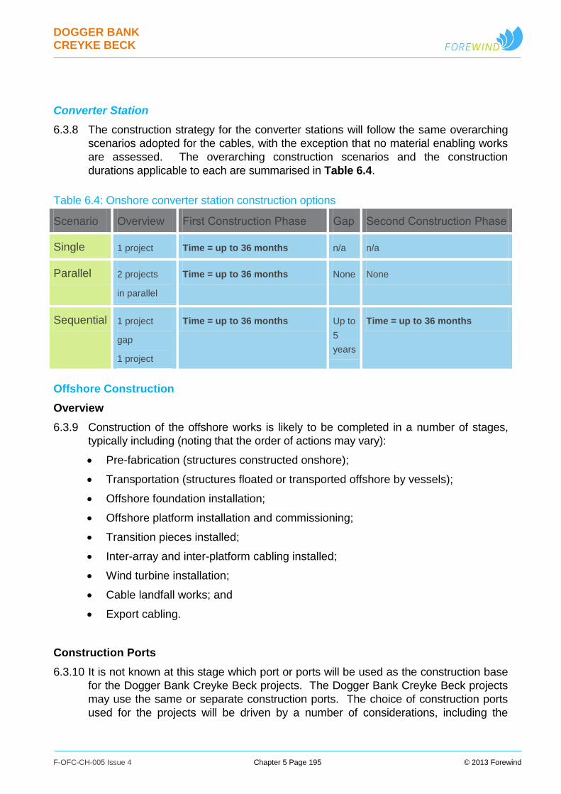
DOGGER BANK CREYKE BECK
F-OFC-CH-005 Issue 4 Chapter 5 Page 195 © 2013 Forewind
Converter Station
6.3.8 The construction strategy for the converter stations will follow the same overarching
scenarios adopted for the cables, with the exception that no material enabling works
are assessed. The overarching construction scenarios and the construction
durations applicable to each are summarised in Table 6.4.
Table 6.4: Onshore converter station construction options
Scenario Overview First Construction Phase Gap Second Construction Phase
Single 1 project Time = up to 36 months n/a n/a
Parallel 2 projects
in parallel
Time = up to 36 months None None
Sequential 1 project
gap
1 project
Time = up to 36 months Up to
5
years
Time = up to 36 months
Offshore Construction
Overview
6.3.9 Construction of the offshore works is likely to be completed in a number of stages,
typically including (noting that the order of actions may vary):
Pre-fabrication (structures constructed onshore);
Transportation (structures floated or transported offshore by vessels);
Offshore foundation installation;
Offshore platform installation and commissioning;
Transition pieces installed;
Inter-array and inter-platform cabling installed;
Wind turbine installation;
Cable landfall works; and
Export cabling.
Construction Ports
6.3.10 It is not known at this stage which port or ports will be used as the construction base
for the Dogger Bank Creyke Beck projects. The Dogger Bank Creyke Beck projects
may use the same or separate construction ports. The choice of construction ports
used for the projects will be driven by a number of considerations, including the
DOGGER BANK CREYKE BECK
F-OFC-CH-005 Issue 4 Chapter 5 Page 196 © 2013 Forewind
technical solutions selected for the execution of the projects, and port availability at
the time of construction. Table 6.5 shows an indicative list of potential construction
ports.
6.3.11 The following port elements may be required for the construction of these projects:
Availability of sufficient marine port space, berthing, deep water and mooring
capabilities to accommodate the required heavy lift, construction support, and
logistical/transportation vessels;
Adequate laydown area for pre-assembly and load-out operations;
Equipment to move the wind farm components, primarily including adequate
crane capacity;
Good transportation links and access by water, road or rail;
24 hour operational availability during the life of the project for unrestricted
access for operations;
Port facilities available for a base to manage construction and other marine
operations.
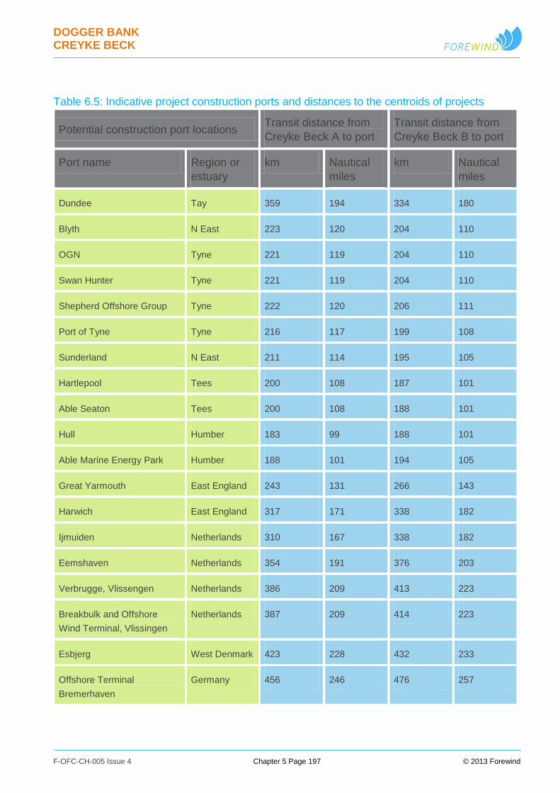
DOGGER BANK CREYKE BECK
F-OFC-CH-005 Issue 4 Chapter 5 Page 197 © 2013 Forewind
Table 6.5: Indicative project construction ports and distances to the centroids of projects
Potential construction port locations Transit distance from
Creyke Beck A to port
Transit distance from
Creyke Beck B to port
Port name Region or
estuary
km Nautical
miles
km Nautical
miles
Dundee Tay 359 194 334 180
Blyth N East 223 120 204 110
OGN Tyne 221 119 204 110
Swan Hunter Tyne 221 119 204 110
Shepherd Offshore Group Tyne 222 120 206 111
Port of Tyne Tyne 216 117 199 108
Sunderland N East 211 114 195 105
Hartlepool Tees 200 108 187 101
Able Seaton Tees 200 108 188 101
Hull Humber 183 99 188 101
Able Marine Energy Park Humber 188 101 194 105
Great Yarmouth East England 243 131 266 143
Harwich East England 317 171 338 182
Ijmuiden Netherlands 310 167 338 182
Eemshaven Netherlands 354 191 376 203
Verbrugge, Vlissengen Netherlands 386 209 413 223
Breakbulk and Offshore
Wind Terminal, Vlissingen
Netherlands 387 209 414 223
Esbjerg West Denmark 423 228 432 233
Offshore Terminal
Bremerhaven
Germany 456 246 476 257
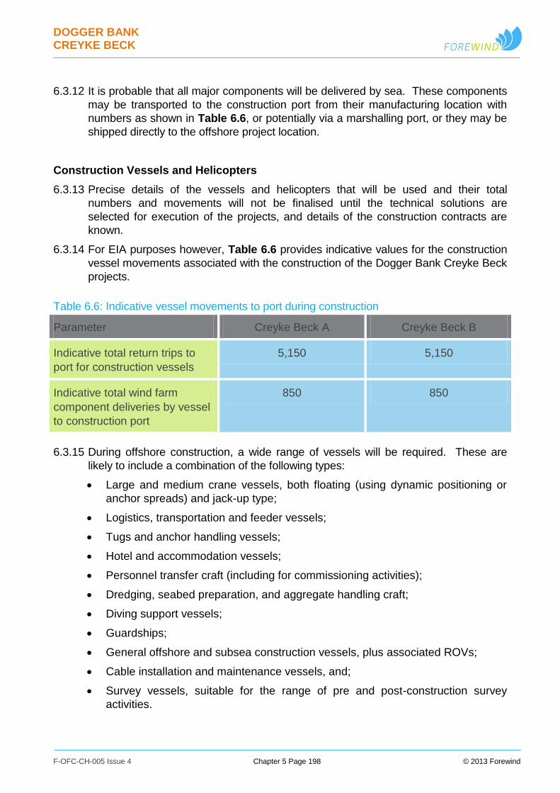
DOGGER BANK CREYKE BECK
F-OFC-CH-005 Issue 4 Chapter 5 Page 198 © 2013 Forewind
6.3.12 It is probable that all major components will be delivered by sea. These components
may be transported to the construction port from their manufacturing location with
numbers as shown in Table 6.6, or potentially via a marshalling port, or they may be
shipped directly to the offshore project location.
Construction Vessels and Helicopters
6.3.13 Precise details of the vessels and helicopters that will be used and their total
numbers and movements will not be finalised until the technical solutions are
selected for execution of the projects, and details of the construction contracts are
known.
6.3.14 For EIA purposes however, Table 6.6 provides indicative values for the construction
vessel movements associated with the construction of the Dogger Bank Creyke Beck
projects.
Table 6.6: Indicative vessel movements to port during construction
Parameter Creyke Beck A Creyke Beck B
Indicative total return trips to
port for construction vessels
5,150 5,150
Indicative total wind farm
component deliveries by vessel
to construction port
850 850
6.3.15 During offshore construction, a wide range of vessels will be required. These are
likely to include a combination of the following types:
Large and medium crane vessels, both floating (using dynamic positioning or
anchor spreads) and jack-up type;
Logistics, transportation and feeder vessels;
Tugs and anchor handling vessels;
Hotel and accommodation vessels;
Personnel transfer craft (including for commissioning activities);
Dredging, seabed preparation, and aggregate handling craft;
Diving support vessels;
Guardships;
General offshore and subsea construction vessels, plus associated ROVs;
Cable installation and maintenance vessels, and;
Survey vessels, suitable for the range of pre and post-construction survey
activities.
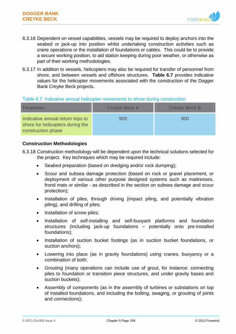
DOGGER BANK CREYKE BECK
F-OFC-CH-005 Issue 4 Chapter 5 Page 199 © 2013 Forewind
6.3.16 Dependent on vessel capabilities, vessels may be required to deploy anchors into the
seabed or jack-up into position whilst undertaking construction activities such as
crane operations or the installation of foundations or cables. This could be to provide
a secure working position, to aid station keeping during poor weather, or otherwise as
part of their working methodologies.
6.3.17 In addition to vessels, helicopters may also be required for transfer of personnel from
shore, and between vessels and offshore structures. Table 6.7 provides indicative
values for the helicopter movements associated with the construction of the Dogger
Bank Creyke Beck projects.
Table 6.7: Indicative annual helicopter movements to shore during construction
Parameter Creyke Beck A Creyke Beck B
Indicative annual return trips to
shore for helicopters during the
construction phase
900 900
Construction Methodologies
6.3.18 Construction methodology will be dependent upon the technical solutions selected for
the project. Key techniques which may be required include:
Seabed preparation (based on dredging and/or rock dumping);
Scour and subsea damage protection (based on rock or gravel placement, or
deployment of various other purpose designed systems such as mattresses,
frond mats or similar - as described in the section on subsea damage and scour
protection);
Installation of piles, through driving (impact piling, and potentially vibration
piling), and drilling of piles;
Installation of screw piles;
Installation of self-installing and self-buoyant platforms and foundation
structures (including jack-up foundations – potentially onto pre-installed
foundations);
Installation of suction bucket footings (as in suction bucket foundations, or
suction anchors);
Lowering into place (as in gravity foundations) using cranes, buoyancy or a
combination of both;
Grouting (many operations can include use of grout, for instance: connecting
piles to foundation or transition piece structures, and under gravity bases and
suction buckets);
Assembly of components (as in the assembly of turbines or substations on top
of installed foundations, and including the bolting, swaging, or grouting of joints
and connections);
DOGGER BANK CREYKE BECK
F-OFC-CH-005 Issue 4 Chapter 5 Page 200 © 2013 Forewind
Installation of pre-assembled components, such as wind turbines (varying levels
of pre-assembly are possible, including the installation of a complete wind
turbine and foundation in one piece);
Cable route preparation where necessary (potentially including methodologies
such as boulder and obstacle clearance, dredging, and pre-sweeping);
Cable installation and burial (typically using powered installation vessels with
dynamic positioning or towed barges, potentially via techniques such as
ploughing, jetting, cutting, etc. as described in the cable installation sections);
Cable protection (including the use of rock burial, mattresses, and proprietary
cable protection systems, as described in the cable protection section. Also
including the construction of cable crossings, as discussed in the crossings
section).
Onshore Construction
Overview
6.3.19 The onshore construction covers the installation of the electrical systems for the
connection of the Dogger Bank Creyke Beck projects. The onshore electrical system
includes the landfall, and then extends from the joint transition bay, where the
onshore cables connect to the offshore cables, to the existing National Grid
substation at Creyke Beck.
6.3.20 The onshore system is comprised of the following main elements:
The HVDC export system underground cables and related auxiliary/ancillary
systems;
The onshore converter stations;
The HVAC export system underground cables; and
National Grid unlicensed works.
6.3.21 Construction of the various elements of the onshore works is likely to be completed in
a number of stages, typically including (noting that the order may vary):
a. Onshore cable systems (applicable to both HVDC and HVAC cables, and
including landfall cables):
i. Construction compound establishment
ii. Civil construction; haul roads and trenches
iii. Cable installation
iv. Horizontal Directional Drill (HDD) installation
v. Jointing and reinstatement
vi. Drainage works
vii. Landscaping and reseeding
b. Converter Stations:
i. Construction site establishment;
ii. Civil construction; sub-structure and buildings;
iii. HVDC equipment installation;
iv. Transformers and outdoor equipment installation;

DOGGER BANK CREYKE BECK
F-OFC-CH-005 Issue 4 Chapter 5 Page 201 © 2013 Forewind
v. AC and DC cable connections installed;
vi. Protection and SCADA equipment installed;
vii. Drainage works
viii. Landscaping and re-seeding
6.3.22 During onshore construction, a wide range of vehicles will be required. These are
likely to include a combination of key vehicle types shown in Table 6.8.
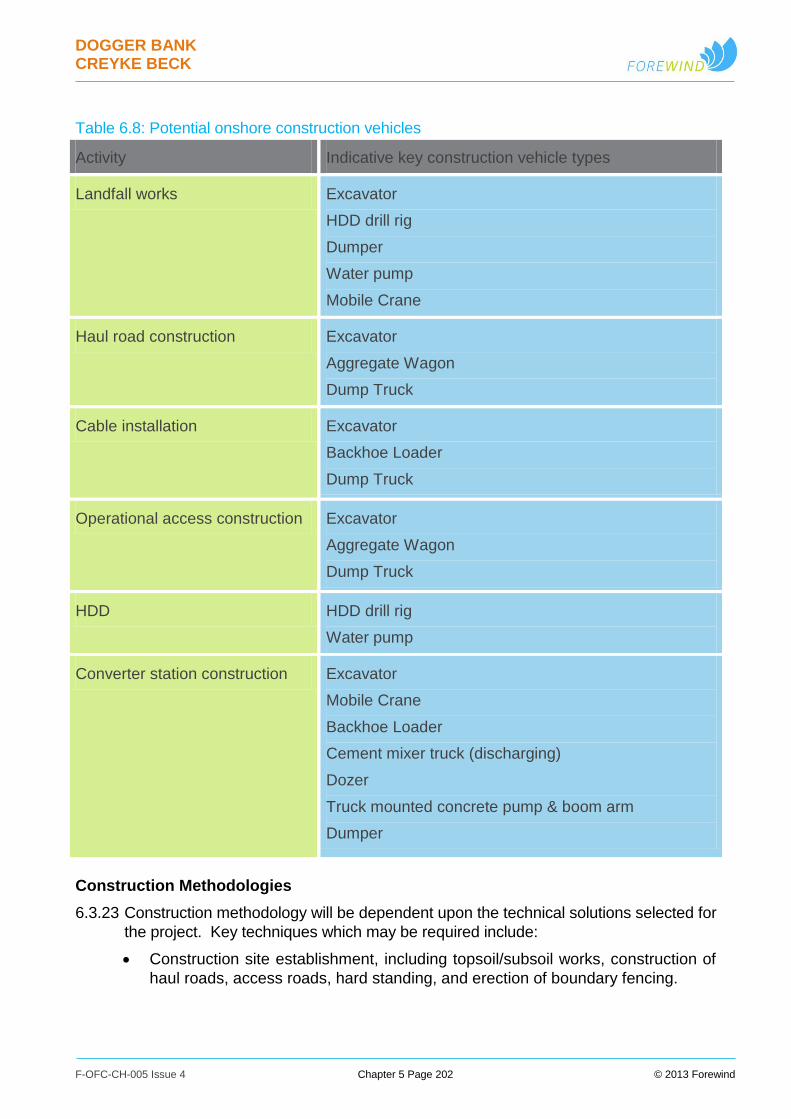
DOGGER BANK CREYKE BECK
F-OFC-CH-005 Issue 4 Chapter 5 Page 202 © 2013 Forewind
Table 6.8: Potential onshore construction vehicles
Activity Indicative key construction vehicle types
Landfall works Excavator
HDD drill rig
Dumper
Water pump
Mobile Crane
Haul road construction Excavator
Aggregate Wagon
Dump Truck
Cable installation Excavator
Backhoe Loader
Dump Truck
Operational access construction Excavator
Aggregate Wagon
Dump Truck
HDD HDD drill rig
Water pump
Converter station construction Excavator
Mobile Crane
Backhoe Loader
Cement mixer truck (discharging)
Dozer
Truck mounted concrete pump & boom arm
Dumper
Construction Methodologies
6.3.23 Construction methodology will be dependent upon the technical solutions selected for
the project. Key techniques which may be required include:
Construction site establishment, including topsoil/subsoil works, construction of
haul roads, access roads, hard standing, and erection of boundary fencing.

DOGGER BANK CREYKE BECK
F-OFC-CH-005 Issue 4 Chapter 5 Page 203 © 2013 Forewind
Civil construction of sub-structure and buildings. Most methodologies are
expected to be typical of large, steel clad, metal frame buildings, with a raft
foundation, bolted and trussed H-beam structure, and cladding for walls and
roof.
High voltage electrical equipment installation. Equipment typically mounted on
insulators atop aluminium frames on individual concrete pad foundations.
Transformers and outdoor equipment installation. Transformers typically
mounted on raft foundations and the equipment on individual pad foundations
AC and DC cable connections installed using open trenching, horizontal
directional drilling, and ducting.
Control, protection and SCADA equipment installed. To include various cubicle-
type equipment mounted into designated equipment rooms within onshore
substation buildings.
Drainage works, including new construction and drainage reinstatement.
Finishing works, including gravel walkways, surrounding roads, security fencing,
landscaping, and reinstatement.
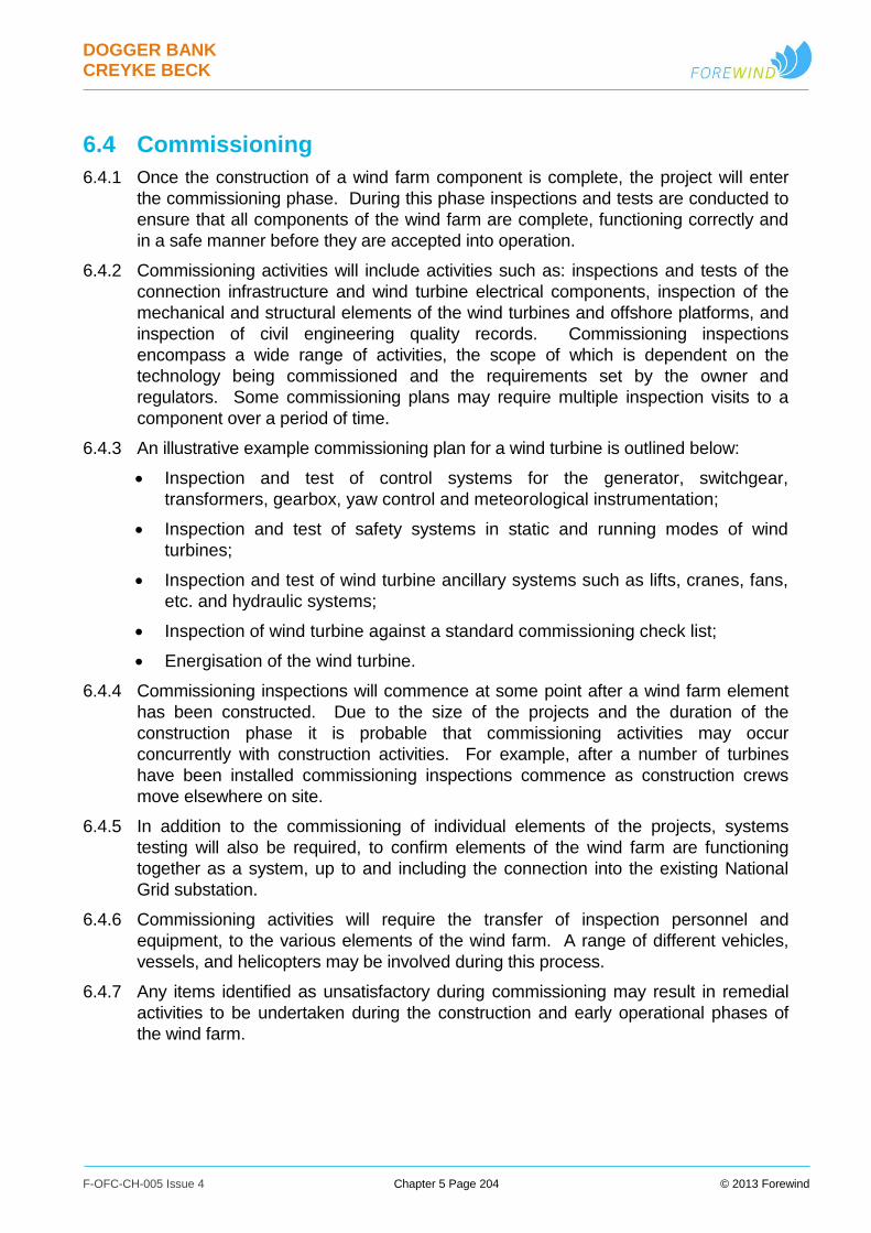
DOGGER BANK CREYKE BECK
F-OFC-CH-005 Issue 4 Chapter 5 Page 204 © 2013 Forewind
6.4 Commissioning
6.4.1 Once the construction of a wind farm component is complete, the project will enter
the commissioning phase. During this phase inspections and tests are conducted to
ensure that all components of the wind farm are complete, functioning correctly and
in a safe manner before they are accepted into operation.
6.4.2 Commissioning activities will include activities such as: inspections and tests of the
connection infrastructure and wind turbine electrical components, inspection of the
mechanical and structural elements of the wind turbines and offshore platforms, and
inspection of civil engineering quality records. Commissioning inspections
encompass a wide range of activities, the scope of which is dependent on the
technology being commissioned and the requirements set by the owner and
regulators. Some commissioning plans may require multiple inspection visits to a
component over a period of time.
6.4.3 An illustrative example commissioning plan for a wind turbine is outlined below:
Inspection and test of control systems for the generator, switchgear,
transformers, gearbox, yaw control and meteorological instrumentation;
Inspection and test of safety systems in static and running modes of wind
turbines;
Inspection and test of wind turbine ancillary systems such as lifts, cranes, fans,
etc. and hydraulic systems;
Inspection of wind turbine against a standard commissioning check list;
Energisation of the wind turbine.
6.4.4 Commissioning inspections will commence at some point after a wind farm element
has been constructed. Due to the size of the projects and the duration of the
construction phase it is probable that commissioning activities may occur
concurrently with construction activities. For example, after a number of turbines
have been installed commissioning inspections commence as construction crews
move elsewhere on site.
6.4.5 In addition to the commissioning of individual elements of the projects, systems
testing will also be required, to confirm elements of the wind farm are functioning
together as a system, up to and including the connection into the existing National
Grid substation.
6.4.6 Commissioning activities will require the transfer of inspection personnel and
equipment, to the various elements of the wind farm. A range of different vehicles,
vessels, and helicopters may be involved during this process.
6.4.7 Any items identified as unsatisfactory during commissioning may result in remedial
activities to be undertaken during the construction and early operational phases of
the wind farm.
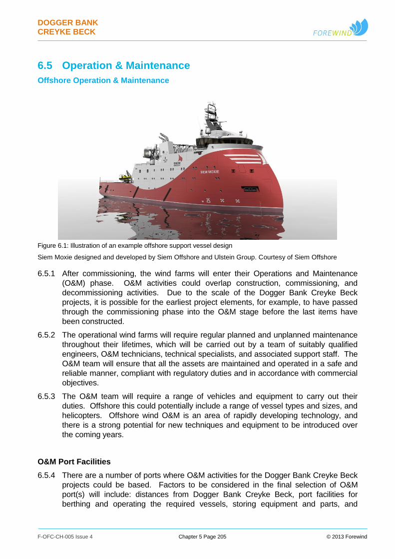
DOGGER BANK CREYKE BECK
F-OFC-CH-005 Issue 4 Chapter 5 Page 205 © 2013 Forewind
6.5 Operation & Maintenance
Offshore Operation & Maintenance
Figure 6.1: Illustration of an example offshore support vessel design
Siem Moxie designed and developed by Siem Offshore and Ulstein Group. Courtesy of Siem Offshore
6.5.1 After commissioning, the wind farms will enter their Operations and Maintenance
(O&M) phase. O&M activities could overlap construction, commissioning, and
decommissioning activities. Due to the scale of the Dogger Bank Creyke Beck
projects, it is possible for the earliest project elements, for example, to have passed
through the commissioning phase into the O&M stage before the last items have
been constructed.
6.5.2 The operational wind farms will require regular planned and unplanned maintenance
throughout their lifetimes, which will be carried out by a team of suitably qualified
engineers, O&M technicians, technical specialists, and associated support staff. The
O&M team will ensure that all the assets are maintained and operated in a safe and
reliable manner, compliant with regulatory duties and in accordance with commercial
objectives.
6.5.3 The O&M team will require a range of vehicles and equipment to carry out their
duties. Offshore this could potentially include a range of vessel types and sizes, and
helicopters. Offshore wind O&M is an area of rapidly developing technology, and
there is a strong potential for new techniques and equipment to be introduced over
the coming years.
O&M Port Facilities
6.5.4 There are a number of ports where O&M activities for the Dogger Bank Creyke Beck
projects could be based. Factors to be considered in the final selection of O&M
port(s) will include: distances from Dogger Bank Creyke Beck, port facilities for
berthing and operating the required vessels, storing equipment and parts, and

DOGGER BANK CREYKE BECK
F-OFC-CH-005 Issue 4 Chapter 5 Page 206 © 2013 Forewind
management base requirements, onshore transport links, and availability of
engineering resources and personnel in the region.
6.5.5 Table 6.9 shows an indicative list of potential O&M ports, including the approximate
distances to the centres of Dogger Bank Creyke Beck projects. The Dogger Bank
Creyke Beck projects may each use the same O&M port facilities or separate port
facilities.
Table 6.9: Indicative O&M ports for Dogger Bank Creyke Beck and distances to centroids of the projects
Indicative O&M port options Transit distance from Creyke Beck A to port
Transit distance from Creyke Beck B to port
Port name Region or estuary
km Nautical miles
km Nautical miles
Blyth North East 223 120 204 110
OGN Group Tyne 221 119 204 110
Swan Hunter Tyne 221 119 204 110
Shepherd Offshore Group Tyne 222 120 206 111
Port of Tyne Tyne 216 117 199 108
Sunderland North East 211 114 195 105
Seaham North East 208 112 193 104
Hartlepool Tees 200 108 187 101
Able Seaton Tees 200 108 188 101
Whitby North East 166 89 157 85
Hull Humber 183 99 188 101
Grimsby & Immingham Dock Humber 185 100 192 104
Grimsby Fish Dock Humber 185 100 193 104
Able Marine Energy Park Humber 188 101 194 105
Great Yarmouth East England 243 131 266 143
Lowestoft East England 256 138 279 150
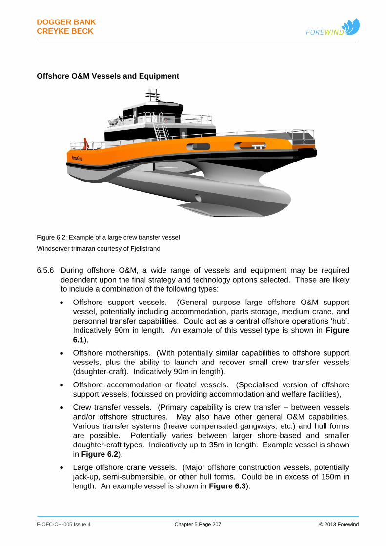
DOGGER BANK CREYKE BECK
F-OFC-CH-005 Issue 4 Chapter 5 Page 207 © 2013 Forewind
Offshore O&M Vessels and Equipment
Figure 6.2: Example of a large crew transfer vessel
Windserver trimaran courtesy of Fjellstrand
6.5.6 During offshore O&M, a wide range of vessels and equipment may be required
dependent upon the final strategy and technology options selected. These are likely
to include a combination of the following types:
Offshore support vessels. (General purpose large offshore O&M support
vessel, potentially including accommodation, parts storage, medium crane, and
personnel transfer capabilities. Could act as a central offshore operations ‘hub’.
Indicatively 90m in length. An example of this vessel type is shown in Figure
6.1).
Offshore motherships. (With potentially similar capabilities to offshore support
vessels, plus the ability to launch and recover small crew transfer vessels
(daughter-craft). Indicatively 90m in length).
Offshore accommodation or floatel vessels. (Specialised version of offshore
support vessels, focussed on providing accommodation and welfare facilities),
Crew transfer vessels. (Primary capability is crew transfer – between vessels
and/or offshore structures. May also have other general O&M capabilities.
Various transfer systems (heave compensated gangways, etc.) and hull forms
are possible. Potentially varies between larger shore-based and smaller
daughter-craft types. Indicatively up to 35m in length. Example vessel is shown
in Figure 6.2).
Large offshore crane vessels. (Major offshore construction vessels, potentially
jack-up, semi-submersible, or other hull forms. Could be in excess of 150m in
length. An example vessel is shown in Figure 6.3).
DOGGER BANK CREYKE BECK
F-OFC-CH-005 Issue 4 Chapter 5 Page 208 © 2013 Forewind
Cable maintenance and repair vessels. (Could vary widely in size up to very
large cable installation vessels if significant cable repairs are required.
Indicatively up to 150m in length).
General purpose, support, and survey vessels. (Including tugs, guardships, and
anchor handlers to support large vessel operations. Also survey vessels, small
cargo and parts transportation, and various specialised and general-purpose
vessels as required to support the operation of Dogger Bank Creyke Beck).
Specialised offshore maintenance equipment. (Including examples such as
remotely operated underwater vehicles (ROVs), autonomous underwater
vehicles (AUVs), and specialised wind turbine cranes which are connected onto
the wind turbine structures to provide a stable base for their operation).
Figure 6.3: GMS Endeavour jack up vessel in operation
Courtesy of Scira Offshore Energy
6.5.7 Offshore O&M may also require the use of helicopters for emergency response,
personnel transfer between shore and offshore vessels or accommodation, and
potentially also to turbines themselves. Suitable helicopter movement parameters
are provided in Table 6.12 assuming an O&M strategy relying primarily on helicopter
transportation. Any helicopters used would be operated in accordance with
appropriate best practice guidance, and all procedures and systems would be
approved in consultation with the Civil Aviation Authority (CAA) and relevant
regulatory authorities.
6.5.8 Fixed accommodation platforms may also be required, co-located with offshore
collector or converter platforms, or separate, and are described in detail within
Section 3.7 Offshore Platforms. Accommodation platforms could also act as a
central offshore operations ‘hub’ in a similar manner to offshore support or
accommodation vessels. Accommodation platforms may also act as a base for
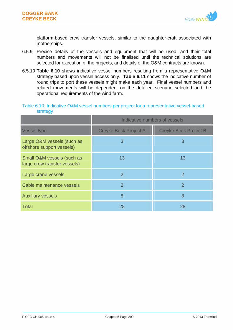
DOGGER BANK CREYKE BECK
F-OFC-CH-005 Issue 4 Chapter 5 Page 209 © 2013 Forewind
platform-based crew transfer vessels, similar to the daughter-craft associated with
motherships.
6.5.9 Precise details of the vessels and equipment that will be used, and their total
numbers and movements will not be finalised until the technical solutions are
selected for execution of the projects, and details of the O&M contracts are known.
6.5.10 Table 6.10 shows indicative vessel numbers resulting from a representative O&M
strategy based upon vessel access only. Table 6.11 shows the indicative number of
round trips to port these vessels might make each year. Final vessel numbers and
related movements will be dependent on the detailed scenario selected and the
operational requirements of the wind farm.
Table 6.10: Indicative O&M vessel numbers per project for a representative vessel-based strategy
Indicative numbers of vessels
Vessel type Creyke Beck Project A Creyke Beck Project B
Large O&M vessels (such as
offshore support vessels)
3 3
Small O&M vessels (such as
large crew transfer vessels)
13 13
Large crane vessels 2 2
Cable maintenance vessels 2 2
Auxiliary vessels 8 8
Total 28 28
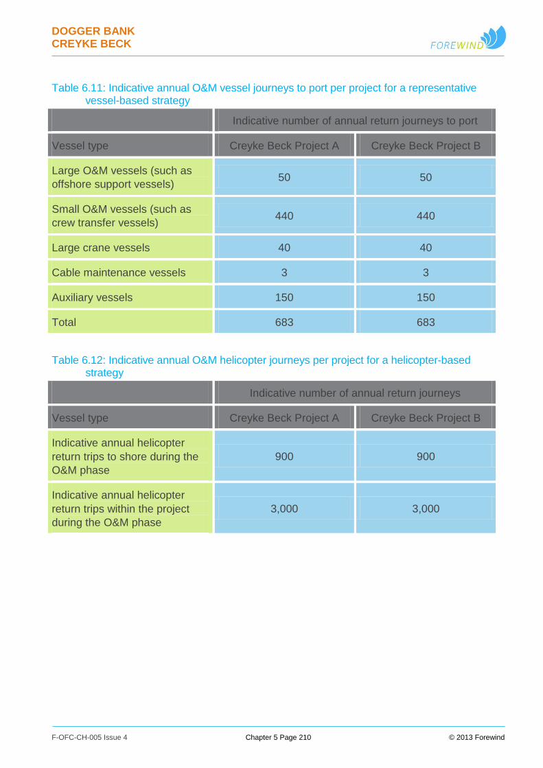
DOGGER BANK CREYKE BECK
F-OFC-CH-005 Issue 4 Chapter 5 Page 210 © 2013 Forewind
Table 6.11: Indicative annual O&M vessel journeys to port per project for a representative vessel-based strategy
Indicative number of annual return journeys to port
Vessel type Creyke Beck Project A Creyke Beck Project B
Large O&M vessels (such as
offshore support vessels) 50 50
Small O&M vessels (such as
crew transfer vessels) 440 440
Large crane vessels 40 40
Cable maintenance vessels 3 3
Auxiliary vessels 150 150
Total 683 683
Table 6.12: Indicative annual O&M helicopter journeys per project for a helicopter-based strategy
Indicative number of annual return journeys
Vessel type Creyke Beck Project A Creyke Beck Project B
Indicative annual helicopter
return trips to shore during the
O&M phase
900 900
Indicative annual helicopter
return trips within the project
during the O&M phase
3,000 3,000
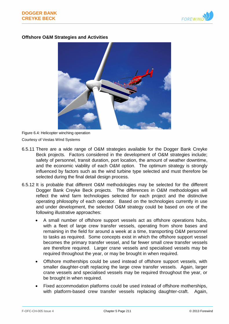
DOGGER BANK CREYKE BECK
F-OFC-CH-005 Issue 4 Chapter 5 Page 211 © 2013 Forewind
Offshore O&M Strategies and Activities
Figure 6.4: Helicopter winching operation
Courtesy of Vestas Wind Systems
6.5.11 There are a wide range of O&M strategies available for the Dogger Bank Creyke
Beck projects. Factors considered in the development of O&M strategies include;
safety of personnel, transit duration, port location, the amount of weather downtime,
and the economic viability of each O&M option. The optimum strategy is strongly
influenced by factors such as the wind turbine type selected and must therefore be
selected during the final detail design process.
6.5.12 It is probable that different O&M methodologies may be selected for the different
Dogger Bank Creyke Beck projects. The differences in O&M methodologies will
reflect the wind farm technologies selected for each project and the distinctive
operating philosophy of each operator. Based on the technologies currently in use
and under development, the selected O&M strategy could be based on one of the
following illustrative approaches:
A small number of offshore support vessels act as offshore operations hubs,
with a fleet of large crew transfer vessels, operating from shore bases and
remaining in the field for around a week at a time, transporting O&M personnel
to tasks as required. Some concepts exist in which the offshore support vessel
becomes the primary transfer vessel, and far fewer small crew transfer vessels
are therefore required. Larger crane vessels and specialised vessels may be
required throughout the year, or may be brought in when required.
Offshore motherships could be used instead of offshore support vessels, with
smaller daughter-craft replacing the large crew transfer vessels. Again, larger
crane vessels and specialised vessels may be required throughout the year, or
be brought in when required.
Fixed accommodation platforms could be used instead of offshore motherships,
with platform-based crew transfer vessels replacing daughter-craft. Again,

DOGGER BANK CREYKE BECK
F-OFC-CH-005 Issue 4 Chapter 5 Page 212 © 2013 Forewind
larger crane vessels and specialised vessels may be required throughout the
year, or be brought in when required.
Helicopters could be used as part of any of the strategies described above, to
assist in the movement of personnel between shore and offshore vessels or
accommodation, and potentially also to turbines themselves, as shown in
Figure 6.4. In the most extreme case, helicopters could be the primary form of
access to offshore structures, in place of crew transfer vessels.
6.5.13 O&M methodologies will be dependent upon the technical solutions and strategies
selected for the project. Key tasks which may be undertaken include:
Inspections and surveys (including of corrosion, cable protection, coatings, wind
turbine components. Also including investigating remotely identified faults. May
be carried out manually or using remote sensing).
Sampling and testing (including of lubricating oils, etc)
Replacement of consumable items (such as filters, and hydraulic oils).
Repair or replacement of worn, failed, or defective systems (such as wind
turbine blades, gearboxes, bolts, corrosion protection systems, protective
coatings, cables, etc. Including cleaning off subsea marine growth, realigning
machinery, renewing cable protection using additional rock dumping or mattress
placement, etc.).
Updating or improving systems (such as control systems, sensors, etc.).
Disposal of waste materials and parts (in line with best practice and regulatory
requirements).
6.5.14 In order to carry out these tasks, a range of activities will be required. Key activities
which may be undertaken include:
transfer of personnel using vessels, helicopters or specialist transfer systems;
lifting;
working at heights;
working in enclosed spaces;
working with high voltage electricity;
diving and other subsea operations (including ROV or AUVs);
transport of parts, consumables and equipment to and from site;
jacking –up, mooring, and anchoring of vessels; and
the safe navigation of vessels and aircraft in and around the site.
Operational Control of the Wind Farm
6.5.15 All elements of the onshore and offshore wind farm projects will be designed to
operate with minimal day-to-day supervisory input, with the key systems monitored
from a central location 24 hours a day.
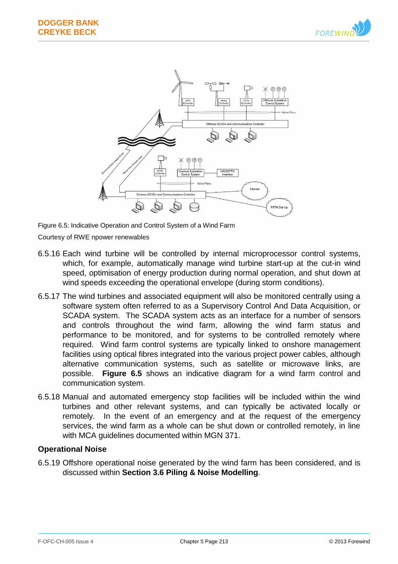
DOGGER BANK CREYKE BECK
F-OFC-CH-005 Issue 4 Chapter 5 Page 213 © 2013 Forewind
Figure 6.5: Indicative Operation and Control System of a Wind Farm
Courtesy of RWE npower renewables
6.5.16 Each wind turbine will be controlled by internal microprocessor control systems,
which, for example, automatically manage wind turbine start-up at the cut-in wind
speed, optimisation of energy production during normal operation, and shut down at
wind speeds exceeding the operational envelope (during storm conditions).
6.5.17 The wind turbines and associated equipment will also be monitored centrally using a
software system often referred to as a Supervisory Control And Data Acquisition, or
SCADA system. The SCADA system acts as an interface for a number of sensors
and controls throughout the wind farm, allowing the wind farm status and
performance to be monitored, and for systems to be controlled remotely where
required. Wind farm control systems are typically linked to onshore management
facilities using optical fibres integrated into the various project power cables, although
alternative communication systems, such as satellite or microwave links, are
possible. Figure 6.5 shows an indicative diagram for a wind farm control and
communication system.
6.5.18 Manual and automated emergency stop facilities will be included within the wind
turbines and other relevant systems, and can typically be activated locally or
remotely. In the event of an emergency and at the request of the emergency
services, the wind farm as a whole can be shut down or controlled remotely, in line
with MCA guidelines documented within MGN 371.
Operational Noise
6.5.19 Offshore operational noise generated by the wind farm has been considered, and is
discussed within Section 3.6 Piling & Noise Modelling.
DOGGER BANK CREYKE BECK
F-OFC-CH-005 Issue 4 Chapter 5 Page 214 © 2013 Forewind
Onshore Operation & Maintenance
Maintenance of Landfall
6.5.20 No maintenance of the landfall is envisaged during the operational phase of the
project. The landfall will be designed to ensure that the cables will remain buried for
the lifetime of the project, allowing for coastal erosion. The cable joints between
onshore and offshore systems may require inspections and/or repairs during the
lifetime of the wind farms, although the joints would be expected to be designed at
the outset for the same design life as the cables.
Onshore Cables
For both HVDC and HVAC cables no planned maintenance activity is envisaged
during the operational phase of the project. A cable system design life of
approximately 40 years is typically provided for by manufacturers. Occasional
access may be required to the cable for fault finding and repair purposes. This would
require the area around the fault to be excavated and the fault repaired. If the fault
cannot be repaired, a new length of cable may be inserted and jointed to replace the
failed section.
Converter stations
6.5.21 Regular access will be required to the converter station throughout the lifetime of the
project for monitoring, fault repairs and planned maintenance purposes. However,
vehicle movements are likely to be low, as significant maintenance activities are
expected to be infrequent. Predicted usage and resulting traffic levels are discussed
in detail within Chapter 28 Traffic and Access.
6.5.22 Onshore converter station noise is discussed in Chapter 29 Noise and Vibration.
6.6 Replanting/Life Extension
6.6.1 The Crown Estate’s leases for the Dogger Bank Creyke Beck wind farms currently
have durations of 50 years. However, manufacturers of the key wind farm
components, including wind turbines and offshore platforms, typically design for an
operational life of 20 to 30 years. This design life varies with the wind farm
component, and depending on operational circumstances it may be possible for a
component to operate beyond the original design life. For example, testing may
identify that a wind turbine structure has experienced lower loading than originally
assumed or key turbine components may be replaced due to routine maintenance or
as part of a planned life extension programme, and this may allow the predicted
operational life to be extended.
In addition to life extension, the wind farm may be replanted at the end of its design
life of 20 to 30 years. It is envisaged that replanting (such as replacement of the wind
turbines) would be subject to an additional planning consent application, and as such
is not considered within the current application and EIA process.
DOGGER BANK CREYKE BECK
F-OFC-CH-005 Issue 4 Chapter 5 Page 215 © 2013 Forewind
6.7 Decommissioning
6.7.1 At the end of the wind farm’s life, decommissioning may be undertaken that broadly
follows a reverse programme to the construction process. The requirement to
decommission is a condition of The Crown Estate lease and is also incorporated in
the statutory consenting process through the provisions of the Energy Act 2004. A
detailed decommissioning plan is required to be set out for the Secretary of State,
and funds must be set aside for the purposes of decommissioning in accordance with
Government’s Guidance Note for ‘Decommissioning Offshore Renewable Energy
Installations under the Energy Act 2004’.
6.7.2 The decommissioning plan will take into account the latest technological advances as
well as legislative and environmental requirements at the time that the work is due to
be undertaken.
6.7.3 Where the operator has opted to undertake replanting, as described previously in
Section 6.6 Replanting/Life Extension, this may result in decommissioning of the
entire wind farm or removal and decommissioning of selected components. For
example, the original turbines may be replaced during re-planting but the offshore
export cables and platforms may remain to continue in use.
6.7.4 Final decommissioning of the Dogger Bank Creyke Beck components or their
replacements would be expected to take place at the end of The Crown Estate lease
term, following a decommissioning EIA. Preliminary decommissioning plans for
some key components of Dogger Bank Creyke Beck are outlined in the following
sections.
Offshore Decommissioning
Decommissioning of Wind Turbines
6.7.5 The removal of the structure is expected to involve the approximate reverse of the
installation process. The following steps are anticipated:
i. Assessment of the potential hazards during planned decommissioning and
development of suitable procedures for mitigating them.
ii. Assessment of potential risk of pollutants entering the environment.
iii. Disconnecting of wind turbines from electrical distribution network and SCADA
system (Including any additional condition monitoring and communications
systems).
iv. Mobilisation of decommissioning vessels.
v. Removal of any potentially hazardous or polluting materials from the turbine. With
the use of appropriate vessels, remove rotor blades, then nacelle, then tower
sections.
vi. Transport all components to onshore facility for processing and
reuse/recycling/disposal.
6.7.6 It should be noted that the decommissioning may not happen in the precise order
outlined above. For example, in a wind turbine with a gearbox it may not be possible
to remove the lubricating oil until after the rotor blades have been removed, as the
gearbox may need to operate to position the rotor prior to removal of the blades.
DOGGER BANK CREYKE BECK
F-OFC-CH-005 Issue 4 Chapter 5 Page 216 © 2013 Forewind
Decommissioning of Offshore Wind Turbine Foundations
Piled foundations
6.7.7 It is envisaged that piled foundations would be cut below seabed level, and the
protruding section removed. Typical current methods for cutting piles are abrasive
water jet cutters or diamond wire cutting. The final method chosen shall be
dependent on the technologies available at the time of decommissioning.
6.7.8 The indicative methodology would be:
i. Deployment of ROV’s or divers to inspect each pile footing and reinstate lifting
attachments if necessary.
ii. Mobilise a jack-up barge/heavy lifting vessel.
iii. Remove any scour protection or sediment obstructing the cutting process. It may be
necessary to dig a small trench around the foundation.
iv. Deploy crane hooks from the decommissioning vessel and attach to the lift points.
v. Cut piles at just below seabed level.
vi. Inspect seabed for debris and remove debris where necessary.
vii. Considering the current technology, the decommissioned components are likely to
be transported back to shore by lifting onto a jack-up or heavy lift vessels, freighter,
barge, or by buoyant tow.
viii. Transport all components to an onshore site where they will be processed for
reuse/recycling/disposal.
ix. Inspect seabed and remove debris.
Decommissioning of Gravity Base Structures
6.7.9 In the case of gravity base foundations, it may be preferable to leave gravity base
structures on the seabed to preserve the marine habitat that has established over
their life, subject to discussions with key stakeholders and regulators. In this case
the central tubular section would be cut off and removed whilst the base remains in
place. However, where removal of the entire base is considered necessary, for
example if it is considered a navigational hazard, it would probably be achieved in a
manner similar to the following:
i. Deploy remotely operated vehicles or divers to establish the base structural integrity
and reinstate lifting attachments if necessary.
ii. Mobilise suction dredging vessel to remove ballast from base and dispose of it
appropriately.
iii. Deploy remotely operated vehicles or diver to inspect the base to ensure remaining
ballast is removed.
iv. Disaggregate compacted sediments below gravity base.
v. Mobilise heavy lift vessel, to lift the bases completely out of the seabed and onto a
transportation vessel.
vi. Transport to an onshore site, where it will be processed for reuse/recycling/disposal.
vii. Inspect seabed and remove debris.
DOGGER BANK CREYKE BECK
F-OFC-CH-005 Issue 4 Chapter 5 Page 217 © 2013 Forewind
Suction Foundations
6.7.10 Suction bucket foundations can be removed using approximately the reverse of the
process required to install them. This could include use of a pump system to apply
pressure inside the buckets, and allow the foundation to be released and extracted
from the seabed. During the release process, any seawater or ballast inside the
foundation shaft could be pumped out to make the structure buoyant, so that it can
be recovered by an appropriate barge for transport from the site.
Decommissioning of Meteorological Monitoring Masts
6.7.11 The removal of the structure is expected to involve the approximate reverse of the
installation process. The methodology would be expected to be broadly similar to
that described above for wind turbine generators and the appropriate foundation type
described above.
Removal of Scour Protection and Subsea Protection
6.7.12 It may be preferable to leave any scour or subsea protection around the turbine
bases or covering cables in-situ, in order to preserve the marine habitat that has
been established over the life of the wind farm. However, if it is considered
preferable to remove the scour protection this could be achieved using the following
techniques:
i. Dredging of the scour protection with subsequent transportation to an approved site
for appropriate disposal or re-use.
ii. For rock fill, the individual boulders may be recovered using a grab vessel,
deposited in a hopper barge, and transported to an approved site for appropriate
disposal or re-use.
iii. For other systems such as frond mats, concrete aprons, or proprietary cable
protection systems, the components could be recovered onto a crane vessel for
appropriate recycling or disposal.
Decommissioning of Offshore Cabling
6.7.13 It is envisaged that, where appropriate, buried assets such as cables will be left in
situ when the project is decommissioned. Discussions with stakeholders and
regulators may identify the need for cables to be wholly or partially removed.
Potential recovery of these cables may then be possible using techniques including
mass flow excavation, grapnels or other available future techniques, but this will
require environmental impact assessment at the time to investigate the potential
effects of the retrieval operations.
6.7.14 An indicative methodology using current technology would be:
i. Identify the location where cable removal is required. This may require deployment
of remotely operated vehicles.
ii. It may be necessary to remove seabed material or cable protection measures to
allow access to the cable.
iii. Mobilise suitable vessels for cable removal.
iv. Using a grapnel the cables will be raised from the seabed.
DOGGER BANK CREYKE BECK
F-OFC-CH-005 Issue 4 Chapter 5 Page 218 © 2013 Forewind
v. The required sections will be cut and removed. The remaining ends weighted and
returned to the seabed
vi. Transport cable to onshore facility for processing and reuse/recycling/disposal.
6.7.15 The question of whether or not cable crossing infrastructure should be left in situ will
also depend on the commercial arrangements and requirements in the individual
crossing agreements.
Decommissioning of Offshore Platforms
Platform Topside
6.7.16 It is envisaged that any offshore platforms, (collector, converter, or accommodation)
will be removed at the end of the project life and returned to shore for
decommissioning, and disposal. The decommissioning programme would be
expected to be similar to the decommissioning method employed for the wind turbine
structures:
i. Assessment of the potential hazards during planned decommissioning and
development of suitable procedures for mitigating them.
ii. Assessment of potential risk of pollutants entering the environment.
iii. Disconnecting of offshore platform from grid and SCADA system (Including any
additional condition monitoring and communications systems).
iv. Mobilisation of decommissioning vessels. It should be noted that a heavy lift vessel
may be required for some tasks.
v. Removal of any potentially hazardous or polluting materials from the offshore
platform.
vi. With the use of appropriate vessels remove topside structure.
vii. Transport all components to onshore facility for processing and
reuse/recycling/disposal.
Platform Foundation
6.7.17 The decommissioning programme for any platform foundations will be dependent on
the foundation type selected for the platform. The decommissioning of the
foundations will be in line with the descriptions given for the wind turbine foundations.
Onshore Decommissioning
Landfall Infrastructure
6.7.18 Landfall infrastructure will be left in-situ where considered appropriate. Any
requirements for decommissioning at the landfall will be agreed with statutory
consultees.
Underground Cables
6.7.19 There is currently no statutory requirement for decommissioned cables to be
removed and it is likely judged that removal of the cables would bring about further
environmental impacts. At present it is therefore proposed that the cables will be left
in-situ, but this will be reviewed over the design life of the project.

DOGGER BANK CREYKE BECK
F-OFC-CH-005 Issue 4 Chapter 5 Page 219 © 2013 Forewind
Onshore Converter Substations
6.7.20 The onshore converter stations for Dogger Bank Creyke Beck, and any associated
equipment, will be removed at the end of the project life, and the land will be restored
and reinstated to their previous condition where feasible.

DOGGER BANK CREYKE BECK
F-OFC-CH-005 Issue 4 Chapter 5 Page 220 © 2013 Forewind
7 Health & Safety and Environmental Management
7.1 Health and Safety
7.1.1 The construction and operation of the projects will be subject to full health, safety and
environment controls and risk assessments. All onshore and offshore construction
and operational work will be conducted in accordance with appropriate best practice
guidelines and in line with the relevant regulatory legislation.
7.1.2 All work throughout the life of both projects will follow the corporate health and safety
policies of their respective owners. Health and safety management systems shall be
put in place. Employment of such systems will enhance health and safety by utilising
experience gained throughout the construction and operation of the wind farm.
Examples of health and safety management systems may include regular inspections
of wind farm elements, routine audits and near-miss reporting. The selection of
health and safety management systems will be dependent on construction and
operation practices used for the projects.
7.1.3 All elements of the projects shall be designed and manufactured in accordance with
the relevant industry codes.
7.1.4 In order to mitigate the impacts of the construction of the onshore works of Dogger
Bank Creyke Beck, both on the amenity of local residents and the local environment,
a broad range of mitigation measures are proposed throughout the draft
Environmental Statement. To bring together and secure all these measures the draft
DCO includes a draft code of construction practice.
7.1.5 If consent is granted, the content of the Code must be approved by East Riding of
Yorkshire Council before construction starts. The requirements of the approved Code
will then be implemented both by the developer and its contractors, and compliance
with the Code will be enforceable by the Council throughout the onshore construction
phase.
7.2 Waste Management
Waste Management Construction Phase
7.2.1 Waste will be generated during the construction of the offshore and onshore
elements of the projects. At this stage it is not possible to estimate waste arising
from construction activities. Waste products will cover a range of substances. These
substances may include, but are not limited to: black water (water containing
sewage, medical waste, etc.), grey water (water from dish washing, bathing, etc.),
bentonite fluid (from horizontal directional drilling), waste grout, component
packaging, and general waste (e.g. food, drinks, cans and general rubbish).
7.2.2 During the installation of the onshore cables and the construction of the converter
station waste top soil and sub soil will be generated. It will be possible to re-use the
majority of this excavated material on site.
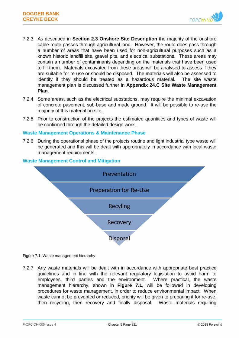
DOGGER BANK CREYKE BECK
F-OFC-CH-005 Issue 4 Chapter 5 Page 221 © 2013 Forewind
7.2.3 As described in Section 2.3 Onshore Site Description the majority of the onshore
cable route passes through agricultural land. However, the route does pass through
a number of areas that have been used for non-agricultural purposes such as a
known historic landfill site, gravel pits, and electrical substations. These areas may
contain a number of contaminants depending on the materials that have been used
to fill them. Materials excavated from these areas will be analysed to assess if they
are suitable for re-use or should be disposed. The materials will also be assessed to
identify if they should be treated as a hazardous material. The site waste
management plan is discussed further in Appendix 24.C Site Waste Management
Plan.
7.2.4 Some areas, such as the electrical substations, may require the minimal excavation
of concrete pavement, sub-base and made ground. It will be possible to re-use the
majority of this material on site.
7.2.5 Prior to construction of the projects the estimated quantities and types of waste will
be confirmed through the detailed design work.
Waste Management Operations & Maintenance Phase
7.2.6 During the operational phase of the projects routine and light industrial type waste will
be generated and this will be dealt with appropriately in accordance with local waste
management requirements.
Waste Management Control and Mitigation
Figure 7.1: Waste management hierarchy
7.2.7 Any waste materials will be dealt with in accordance with appropriate best practice
guidelines and in line with the relevant regulatory legislation to avoid harm to
employees, third parties and the environment. Where practical, the waste
management hierarchy, shown in Figure 7.1, will be followed in developing
procedures for waste management, in order to reduce environmental impact. When
waste cannot be prevented or reduced, priority will be given to preparing it for re-use,
then recycling, then recovery and finally disposal. Waste materials requiring
Preventation
Preperation for Re-Use
Recyling
Recovery
Disposal
DOGGER BANK CREYKE BECK
F-OFC-CH-005 Issue 4 Chapter 5 Page 222 © 2013 Forewind
controlled disposal may be sent to licenced contractors for controlled recycling or
disposal dependent on the waste material.
7.2.8 Vessels, offshore substation platforms and onshore converter stations will include
drainage and waste management systems, as required to meet regulatory
requirements. These will collect waste products such as grey and black water, and
waste oil. Bunding, to collect and contain leaks, will be included around relevant
areas as required.
7.2.9 Waste management systems may store waste products for controlled processing or
disposal onshore or elsewhere, or incorporate appropriate purification units which
comply with requirements if waste is to be discharged to the sea.
7.2.10 A fuller description of waste management can be found in Appendix 24.C Site
Waste Management Plan.
7.3 Hazardous Material
Hazardous Material Construction Phase
7.3.1 During the construction of the offshore and onshore elements of the projects a limited
amount of hazardous or polluting materials may be used. Potential materials may
include, but are not limited to; fuel, lubricants, grouting material, epoxy-based
materials and drilling fluid. In addition to the materials listed, construction activities,
such as welding, may result in dust or fumes that will be treated as hazardous.
7.3.2 Electrical components also contain a number of hazardous materials which may be
released during the construction phase. Potential materials may include, but are not
limited to; insulating oil in transformers and sulphur hexafluoride gas used in switch
gear.
Hazardous Material Operations and Maintenance Phase
7.3.3 Hazardous or polluting materials may be generated as a result of operations &
maintenance activities for Dogger Bank Creyke Beck. The primary waste products
generated by the routine maintenance of the wind turbines and substation platforms
may include:
Gearbox and other lubricating oils from preventive and corrective maintenance.
Lubricating grease in turbines from preventive and corrective maintenance.
Hydraulic Oil in turbines from preventive and corrective maintenance activities.
Sulphur hexafluoride in gas insulated switchgear both on the turbines and
substation platforms.
7.3.4 In addition to the materials listed above, operation and maintenance activities, such
as grinding, may result in dust or fumes that may be treated as hazardous.
7.3.5 During the operation & maintenance phase a number of other hazardous materials
may be held on site. These materials are required for operation of the wind farm.
DOGGER BANK CREYKE BECK
F-OFC-CH-005 Issue 4 Chapter 5 Page 223 © 2013 Forewind
Potential materials may include, but are not limited to; insulating oil for transformers,
glycol for cooling plant, fuel & epoxy-based materials.
7.3.6 However, it should be noted that types and quantities of material will be dependent
on the type of equipment used on site and the activities undertaken. For example, a
wind turbine using a hydraulic transmission system will have no gearbox oil, but a
greater quantity of hydraulic fluid.
Hazardous Material Control and Mitigation Phase
7.3.7 Any hazardous or polluting materials will be dealt with in accordance with appropriate
best practice guidelines and in line with the relevant regulatory instructions to avoid
harm to employees, third parties and the marine environment. Where possible the
requirement for hazardous materials on site during the construction and operational
phases of the projects will be eliminated, reduced or isolated.
7.3.8 Where hazardous materials cannot be eliminated, control measures shall be put in
place. Methods may include the installation of bunding, appropriate ventilation, or
vapour detection systems. Where it is deemed that the failure of an item of
equipment might result in large quantities of a hazardous material being leaked
additional measures shall be put in place. For example, oil containing transformers
at the onshore converter station may have secondary containment incorporated
through an underground containment facility with the addition of further safety
measures such as flame traps. The additional measures shall be dependent on the
technology used and the risks identified.
7.3.9 In addition, during both the construction and operation phases, procedures and
management systems will be put in place to mitigate against the release of
hazardous or polluting materials. This shall include procedures describing the
handling of hazardous or polluting materials and plans put in place to respond to any
emergency activity, such as a spill.
7.3.10 Where possible, hazardous or polluting waste materials will be dealt with in
accordance with the waste hierarchy as described in Section 7.2. Hazardous or
polluting materials requiring disposal will be sent to licenced contractors for controlled
recycling or disposal.
DOGGER BANK CREYKE BECK
F-OFC-CH-005 Issue 4 Chapter 5 Page 224 © 2013 Forewind
7.4 Safety Zones and Other Potential Navigation Safety Measures
7.4.1 During the lifetime of the Dogger Bank Creyke Beck projects, permanent and
temporary safety zones may be requested around individual structures. Safety
zones are intended to ensure the safety of other sea users and to avoid damage to
marine infrastructure by creating defined areas which may typically not be entered by
other marine users. In addition, charted Development Areas (DAs), Areas to Be
Avoided (ATBAs) or other similar advisory safety designations, may be requested to
clearly communicate the potential hazards associated with transit through a wind
farm area. The ultimate need for navigational safety measures will be kept under
review and defined based on the final project design, on-going risk reviews, and in
consultation with the relevant marine authorities. It is noted that under the Energy
Act 2004, the Secretary of State may impose alternative arrangements for
operational safety zones where this is considered appropriate and that the need for
safety zones can be reviewed as further information becomes available throughout
project life.
7.4.2 During construction, commissioning, decommissioning and any exceptional major
maintenance works, safety zones of up to 500m radius may be sought around active
works, and potentially any hazardous partially completed structures.
7.4.3 Safety zones are not expected to be requested for the operational phase of Dogger
Bank Creyke Beck, with the possible exception of activities discussed above, and key
structures such as offshore collector, converter or accommodation platforms, for
which up to 500m safety zones may be requested.
7.4.4 DAs, ATBAs and other similar advisory safety designations are not being requested
at this time, as part of the initial construction and operation of the project, but the
need for them will be kept under review. Such measures would be intended to
clearly communicate, via a charted area and note, that navigation and other marine
operations close to and within the wind farm boundaries may experience specific
hazards and are discouraged where possible. They would not be intended to enable
any prosecutions of vessels entering the areas. It is anticipated that the defined
areas would cover the full wind farm array areas, plus potentially any spaces
between adjacent projects and appropriate buffers around them. In the event areas
were requested during construction, the potential to introduce them in a phased
manner as construction progresses across the project areas would be explored.
Should a need be identified in the future, details of any proposed areas would be
presented to the MCA and other navigational stakeholders at a suitable time, for
further discussion.
7.4.5 Reference should also be made to the DCO Safety Zones Statement, and Chapter
16 Shipping and Navigation and associated appendices.
DOGGER BANK CREYKE BECK
F-OFC-CH-005 Issue 4 Chapter 5 Page 225 © 2013 Forewind
7.5 Navigation and Aviation Safety Markings
7.5.1 The project as a whole, plus individual components, such as offshore platforms,
meteorological masts, turbines and associated support structures will bear safety
markings, lighting, and aids to navigation in accordance with the United Kingdom
Maritime and Coastguard Agency (MCA), Trinity House, and Civil Aviation Authority
(CAA) requirements. The final marking and lighting requirements will ultimately
depend upon the final project design and will be developed in consultation with these
organisations; Trinity House, MCA and the CAA. Indicative marking requirements
are expected to include the following:
Transition pieces and above-water foundation structures shall be painted high-
visibility yellow to approximately 15m above highest astronomical tide (HAT);
Significant peripheral structures (SPS - such as turbines on the corners of the
array) and intermediate peripheral structures (IPS - such as turbines in the
middle of a long edge) shall have yellow navigation lights positioned, and with a
range and flash characteristic, as agreed with Trinity House;
Individual isolated structures outside the turbine array will be marked with a
white navigation light flashing morse code “U”, as per the standard IALA
(International Association of Lighthouse Authorities), and Trinity House,
requirement;
Navigation sound signals will be installed where necessary, with characteristics
as agreed with Trinity House;
Individual wind turbines, offshore platforms, and met masts will be marked with
a unique alphanumeric identifier which is designed and lit so as to be clearly
visible at a distance of not less than 150m in day or night without interfering with
navigational lighting;
The wind farm will be marked with fixed red and/or infrared aviation warning
lights as required by the CAA and MOD. It is expected that only a limited
number of turbines would be lit, located similarly to the SPS, typically with lights
fitted to the turbine nacelles;
The positions of all offshore structures and sub-sea cables will be reported to
the UK Hydrographic Office so that they can be appropriately charted and
incorporated into notice to mariner procedures. All relevant information will also
be supplied to the MCA, CAA, fishermen, and other key stakeholders to ensure
necessary information is available to other sea users;
7.5.2 In addition, construction phase lighting and marking will be agreed with Trinity House,
to include aspects such as any detailed requirements for lighting and/or marking
partially completed structures.
7.5.3 Reference should also be made to Chapter 16 Shipping and Navigation, Chapter
19 Military Activities, Chapter 20 Civil Aviation and their associated appendices.

DOGGER BANK CREYKE BECK
F-OFC-CH-005 Issue 4 Chapter 5 Page 226 © 2013 Forewind
Recommended