**
Two Piece Trunnion Ball ValvesASME Class 150, 300, 600 900
ENTECH CONTROLSPneumat ic Actuators & Bal l Valves
TR
UN
NIO
N B
AL
L V
ALV
ES

STEMAnti-blowout proof stem permits the replacement of the stem seals with the valve in the fully closed or open
position.
FLOATING SEAT RINGTwo independent floating seat rings assure the bi-directional tightness of the valve from zero differential
pressure to the maximum rated pressure.
SELF-RELIEVING SEAT DESIGNWhen the valve is in the closed position, media will be trapped in the body cavity. Unless this media is drained,
it will be subjected to thermal expansion and contraction. As the temperature rises, the trapped media desires
to expand and the pressure build-up, the ECI seats are designed to self-relieve, allowing the media in the body
to escape into the pipeline.
ANTI-STATIC DESIGNStems feature anti-static grounding device as standard. These devices ensure electrical continuity between
valve ball, stem and body, thus eliminating the possibility of static electrical charges creating sparks within the
valve.
TRUNNION-MOUNTED BALLThe ball is supported and the seat rings are floating. Free to move along the flow axis. As the pressure
increases the fluid pressure increases the fluid pressure pushes the seat rings against the ball.
BODY JOINTSDouble seal combination of o-ring and fire safe graphite ensures perfect body joint sealing. ECI Trunnion Ball
Valves meet or exceed the fugitive emission requirements across a wide range of pressure and temperature
applications. Valves are suitable for both above and underground installations.
FIRE SAFE DESIGNECI fire safe design consists of a primary soft sealing and a secondary metal seat. A resilient material is
inserted into the metal seat holder to provide a soft action in addition to the metal sealing between the ball and
seat rings. In case of fire the soft seat insert burns and allows the spring loaded seat to insure metal to metal
sealing against the ball.
STEM SEALINGA combination of O-rings and gland packing ensures tight sealing and prevents any leakage. A graphite seal is
also provided at the top of the steam housing.
DESIGN FEATURES
vDesign Standards
v
v
v
v
v
v
Inspection & Testing
Flange Dimensions
v Fire Safe Test
Butt Weld Valve Ends
Drain/ Vent /Bypass
Face to Face
Pressure Temperature
- -
- -
- - -
-
API 6D/ASME 16.34/EN ISO 17292(BS 5351)
API 6D /API 598/BS EN 12266-1(BS6755-1)
ASME B16.5 / MSS-SP-44 /ASME B16.1
API 607 – ISO 10497 – 5 /API 6FA /BS EN 12266-2
ASME B 16.25/31.3/31.4/31.5
MSS SP 45/ API 6D
API 6D/ ASME 16.10/ISO 5752
ASME B16.34/BS EN 12516-I
STANDARDS
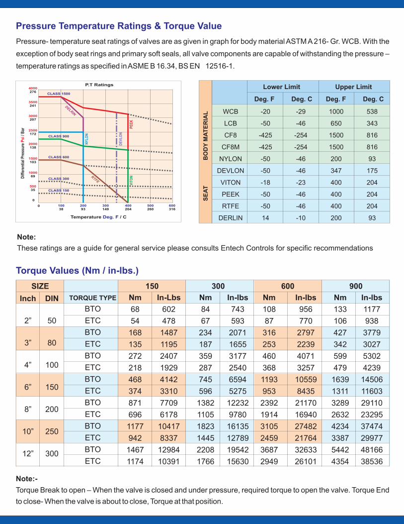
Pressure- temperature seat ratings of valves are as given in graph for body material ASTM A 216- Gr. WCB. With the
exception of body seat rings and primary soft seals, all valve components are capable of withstanding the pressure –
temperature ratings as specified in ASME B 16.34, BS EN 12516-1.
Note:
These ratings are a guide for general service please consults Entech Controls for specific recommendations
Note:-
Torque Break to open – When the valve is closed and under pressure, required torque to open the valve. Torque End
to close- When the valve is about to close, Torque at that position.
Pressure Temperature Ratings & Torque Value
WCB
LCB
CF8
CF8M
NYLON
DEVLON
VITON
PEEK
RTFE
DERLIN
Lower Limit Upper Limit
Deg. F Deg. C Deg. F Deg. C
SE
AT
BO
DY
MA
TE
RIA
L -20
-50
-425
-425
-50
-50
-18
-50
-50
14
-29
-46
-254
-254
-46
-46
-23
-46
-46
-10
1000
650
1500
1500
200
347
400
400
400
200
538
343
816
816
93
175
204
204
204
93
4000276
3500241
3000207
2500172
2000138
1500103
100069
0
0 10038
20093
300149
400204
500260
Temperature / CDeg. F
Diff
eren
tial P
ress
ure
/ B
arP
si
600316
50035 CLASS 150
CLASS 300
CLASS 600
CLASS 900
CLASS 1500
DELRIN
NY
LON
DE
VLO
N
PE
EK
VIT
ONRTFE
P.T Ratings
TORQUE TYPE
BTO
ETC
BTO
ETC
BTO
ETC
BTO
ETC
BTO
ETC
BTO
ETC
BTO
ETC
Nm
68
54
168
135
272
218
468
374
871
696
1177
942
1467
1174
In-Lbs
602
478
1487
1195
2407
1929
4142
3310
7709
6178
10417
8337
12984
10391
Nm
84
67
234
187
359
287
745
596
1382
1105
1823
1445
2208
1766
In-lbs
743
593
2071
1655
3177
2540
6594
5275
12232
9780
16135
12789
19542
15630
Nm
108
87
316
253
460
368
1193
953
2392
1914
3105
2459
3687
2949
In-lbs
956
770
2797
2239
4071
3257
10559
8435
21170
16940
27482
21764
32633
26101
Nm
133
106
427
342
599
479
1639
1311
3289
2632
4234
3387
5442
4354
In-lbs
1177
938
3779
3027
5302
4239
14506
11603
29110
23295
37474
29977
48166
38536
Inch
2”
3”
4”
6”
8”
10”
12”
DIN
50
80
100
150
200
250
300
SIZE 150 300 600 900
Torque Values (Nm / in-lbs.)
Valve Size
INCH DN
50
80
100
150
200
250
300
2”
3”
4”
6”
8”
10”
12”
51
76
102
152
203
254
305
RF
292
365
432
599
660
787
838
RTF BWE
295
359
435
562
664
791
841
292
365
432
559
660
787
838
133
185
192
233
282
355
395
125
150
210
210
300
300
350
102
125
165
165
165
254
298
ØG ØJA E
12
14
22
22
22
18
22
4
4
4
4
4
8
8
NOSPCD HOLEØ
ISO TOP ØD
25
40
40
45
55
63.5
76.2
B
40
60
60
70
70
102
102
KEY SIZE
8x7
12x8
14x9
14x9
16x10
15.88x15.88
19.05x19.05
ØI
165
210
275
355
420
445
560
NOSBC HOLEØ
127
168.3
215.9
292.1
349.2
387.4
489
19
22.2
25.4
28.5
31.8
28.5
35
8
8
8
12
12
16
20
25
65
97
210
460
360
845
Wt.(Kg)FLANGE DRILLING
Valve Size
INCH DN
50
80
100
150
200
250
300
2”
3”
4”
6”
8”
10”
12”
51
76
102
152
203
254
305
RF
368
381
457
610
737
838
965
RTF BWE
371
384
460
613
740
841
968
368
381
457
610
737
838
965
145
195
210
250
295
355
395
125
150
210
210
300
300
350
102
125
165
165
254
254
298
ØG ØJA E
12
14
22
22
18
18
22
4
4
4
4
8
8
8
NOSPCD HOLEØ
ISO TOP ØD
30
45
45
55
55
76.2
76.2
B
45
70
70
70
70
102
102
KEY SIZE
8x7
14x9
14x9
16x10
16x10
19.05x19.05
19.05x19.05
ØI
215
240
290
380
470
545
610
NOSBC HOLEØ
165.1
190.5
235
317.5
393.7
469.9
533.4
25.4
25.4
31.8
31.8
38.1
38.1
38.1
8
8
8
12
12
16
20
55
85
127
284
400
845
1115
Wt.(Kg)FLANGE DRILLING
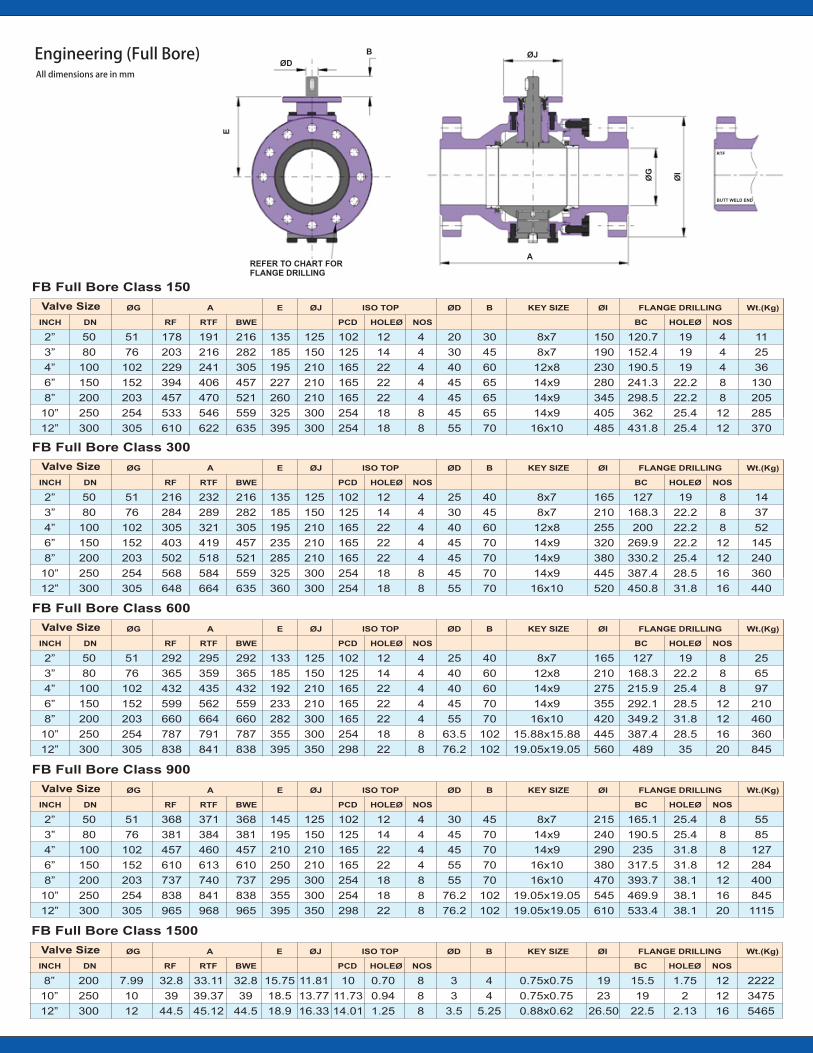
FB Full Bore Class 600
FB Full Bore Class 900
Valve Size
INCH DN
50
80
100
150
200
250
300
2”
3”
4”
6”
8”
10”
12”
51
76
102
152
203
254
305
REFER TO CHART FORFLANGE DRILLING
ØD
B
E
A
ØG
ØI
BUTT WELD END
RTF
ØJ
RF
216
284
305
403
502
568
648
RTF BWE
232
289
321
419
518
584
664
216
282
305
457
521
559
635
135
185
195
235
285
325
360
125
150
210
210
210
300
300
102
125
165
165
165
254
254
ØG ØJA E
12
14
22
22
22
18
18
4
4
4
4
4
8
8
NOSPCD HOLEØ
ISO TOP ØD
25
30
40
45
45
45
55
B
40
45
60
70
70
70
70
KEY SIZE
8x7
8x7
12x8
14x9
14x9
14x9
16x10
ØI
165
210
255
320
380
445
520
NOSBC HOLEØ
127
168.3
200
269.9
330.2
387.4
450.8
19
22.2
22.2
22.2
25.4
28.5
31.8
8
8
8
12
12
16
16
14
37
52
145
240
360
440
Wt.(Kg)FLANGE DRILLING
FB Full Bore Class 300
Valve Size
INCH DN
50
80
100
150
200
250
300
2”
3”
4”
6”
8”
10”
12”
51
76
102
152
203
254
305
RF
178
203
229
394
457
533
610
RTF BWE
191
216
241
406
470
546
622
216
282
305
457
521
559
635
135
185
195
227
260
325
395
125
150
210
210
210
300
300
102
125
165
165
165
254
254
ØG ØJA E
12
14
22
22
22
18
18
4
4
4
4
4
8
8
NOSPCD HOLEØ
ISO TOP ØD
20
30
40
45
45
45
55
B
30
45
60
65
65
65
70
KEY SIZE
8x7
8x7
12x8
14x9
14x9
14x9
16x10
ØI
150
190
230
280
345
405
485
NOSBC HOLEØ
120.7
152.4
190.5
241.3
298.5
362
431.8
19
19
19
22.2
22.2
25.4
25.4
4
4
4
8
8
12
12
11
25
36
130
205
285
370
Wt.(Kg)FLANGE DRILLING
FB Full Bore Class 150
Valve Size
INCH DN
200
250
300
8”
10”
12”
7.99
10
12
RF
32.8
39
44.5
RTF BWE
33.11
39.37
45.12
32.8
39
44.5
15.75
18.5
18.9
11.81
13.77
16.33
10
11.73
14.01
ØG ØJA E
0.70
0.94
1.25
8
8
8
NOSPCD HOLEØ
ISO TOP ØD
3
3
3.5
B
4
4
5.25
KEY SIZE
0.75x0.75
0.75x0.75
0.88x0.62
ØI
19
23
26.50
NOSBC HOLEØ
15.5
19
22.5
1.75
2
2.13
12
12
16
2222
3475
5465
Wt.(Kg)FLANGE DRILLING
FB Full Bore Class 1500
Engineering (Full Bore) All dimensions are in mm
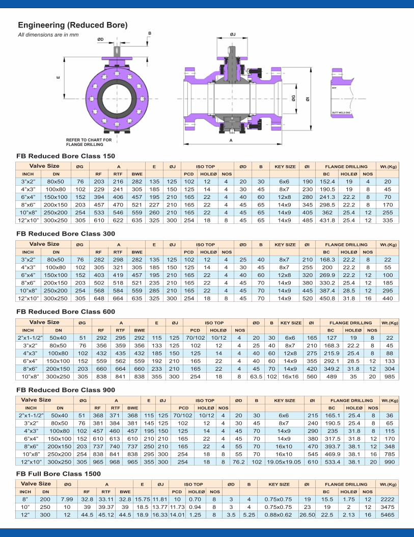
Engineering (Reduced Bore) All dimensions are in mm
Valve Size
INCH DN
50x40
80x50
100x80
150x100
200x150
250x200
300x250
2”x1-1/2”
3”x2”
4”x3”
6”x4”
8”x6”
10”x8”
12”x10”
51
76
102
152
203
254
305
RF
368
381
457
610
737
838
965
RTF BWE
371
384
460
613
740
841
968
368
381
457
610
737
838
965
115
145
195
210
250
295
355
125
125
150
210
210
300
300
70/102
102
125
165
165
254
254
ØG ØJA E
10/12
12
14
22
22
18
18
4
4
4
4
4
8
8
NOSPCD HOLEØ
ISO TOP ØD
20
30
45
45
55
55
76.2
B
30
45
70
70
70
70
102
KEY SIZE
6x6
8x7
14x9
14x9
16x10
16x10
19.05x19.05
ØI
215
240
290
380
470
545
610
NOSBC HOLEØ
165.1
190.5
235
317.5
393.7
469.9
533.4
25.4
25.4
31.8
31.8
38.1
38.1
38.1
8
8
8
12
12
16
20
36
65
115
170
348
785
990
Wt.(Kg)FLANGE DRILLING
FB Reduced Bore Class 600
FB Reduced Bore Class 900
FB Reduced Bore Class 300
Valve Size
INCH DN
80x50
100x80
150x100
200x150
250x200
300x250
3”x2”
4”x3”
6”x4”
8”x6”
10”x8”
12”x10”
76
102
152
203
254
305
RF
203
229
394
457
533
610
RTF BWE
216
241
406
470
546
622
282
305
457
521
559
635
135
185
195
227
260
325
125
150
210
210
210
300
102
125
165
165
165
254
ØG ØJA E
12
14
22
22
22
18
4
4
4
4
4
8
NOSPCD HOLEØ
ISO TOP ØD
20
30
40
45
45
45
B
30
45
60
65
65
65
KEY SIZE
6x6
8x7
12x8
14x9
14x9
14x9
ØI
190
230
280
345
405
485
NOSBC HOLEØ
152.4
190.5
241.3
298.5
362
431.8
19
19
22.2
22.2
25.4
25.4
4
8
8
8
12
12
20
45
70
170
255
335
Wt.(Kg)FLANGE DRILLING
FB Reduced Bore Class 150
Valve Size
INCH DN
200
250
300
8”
10”
12”
7.99
10
12
RF
32.8
39
44.5
RTF BWE
33.11
39.37
45.12
32.8
39
44.5
15.75
18.5
18.9
11.81
13.77
16.33
10
11.73
14.01
ØG ØJA E
0.70
0.94
1.25
8
8
8
NOSPCD HOLEØ
ISO TOP ØD
3
3
3.5
B
4
4
5.25
KEY SIZE
0.75x0.75
0.75x0.75
0.88x0.62
ØI
19
23
26.50
NOSBC HOLEØ
15.5
19
22.5
1.75
2
2.13
12
12
16
2222
3475
5465
Wt.(Kg)FLANGE DRILLING
FB Full Bore Class 1500
Valve Size
INCH DN
80x50
100x80
150x100
200x150
250x200
300x250
3”x2”
4”x3”
6”x4”
8”x6”
10”x8”
12”x10”
76
102
152
203
254
305
RF
282
305
403
502
568
648
RTF BWE
298
321
419
518
584
664
282
305
457
521
559
635
135
185
195
235
285
325
125
150
210
210
210
300
102
125
165
165
165
254
ØG ØJA E
12
14
22
22
22
18
4
4
4
4
4
8
NOSPCD HOLEØ
ISO TOP ØD
25
30
40
45
45
45
B
40
45
60
70
70
70
KEY SIZE
8x7
8x7
12x8
14x9
14x9
14x9
ØI
210
255
320
380
445
520
NOSBC HOLEØ
168.3
200
269.9
330.2
387.4
450.8
22.2
22.2
22.2
25.4
28.5
31.8
8
8
12
12
12
16
22
55
100
185
295
440
Wt.(Kg)FLANGE DRILLING
Valve Size
INCH DN
50x40
80x50
100x80
150x100
200x150
300x250
2”x1-1/2”
3”x2”
4”x3”
6”x4”
8”x6”
10”x8”
51
76
102
152
203
305
RF
292
356
432
559
660
838
RTF BWE
295
359
435
562
664
841
292
356
432
559
660
838
115
133
185
192
233
355
125
125
150
210
210
300
70/102
102
125
165
165
254
ØG ØJA E
10/12
12
14
22
22
18
4
4
4
4
4
8
NOSPCD HOLEØ
ISO TOP ØD
20
25
40
40
45
63.5
B
30
40
60
60
70
102
KEY SIZE
6x6
8x7
12x8
14x9
14x9
16x16
ØI
165
210
275
355
420
560
NOSBC HOLEØ
127
168.3
215.9
292.1
349.2
489
19
22.2
25.4
28.5
31.8
35
8
8
8
12
12
20
22
45
88
133
304
985
Wt.(Kg)FLANGE DRILLING
REFER TO CHART FORFLANGE DRILLING
ØD
B
E
A
ØG
ØI
BUTT WELD END
RTF
ØJ
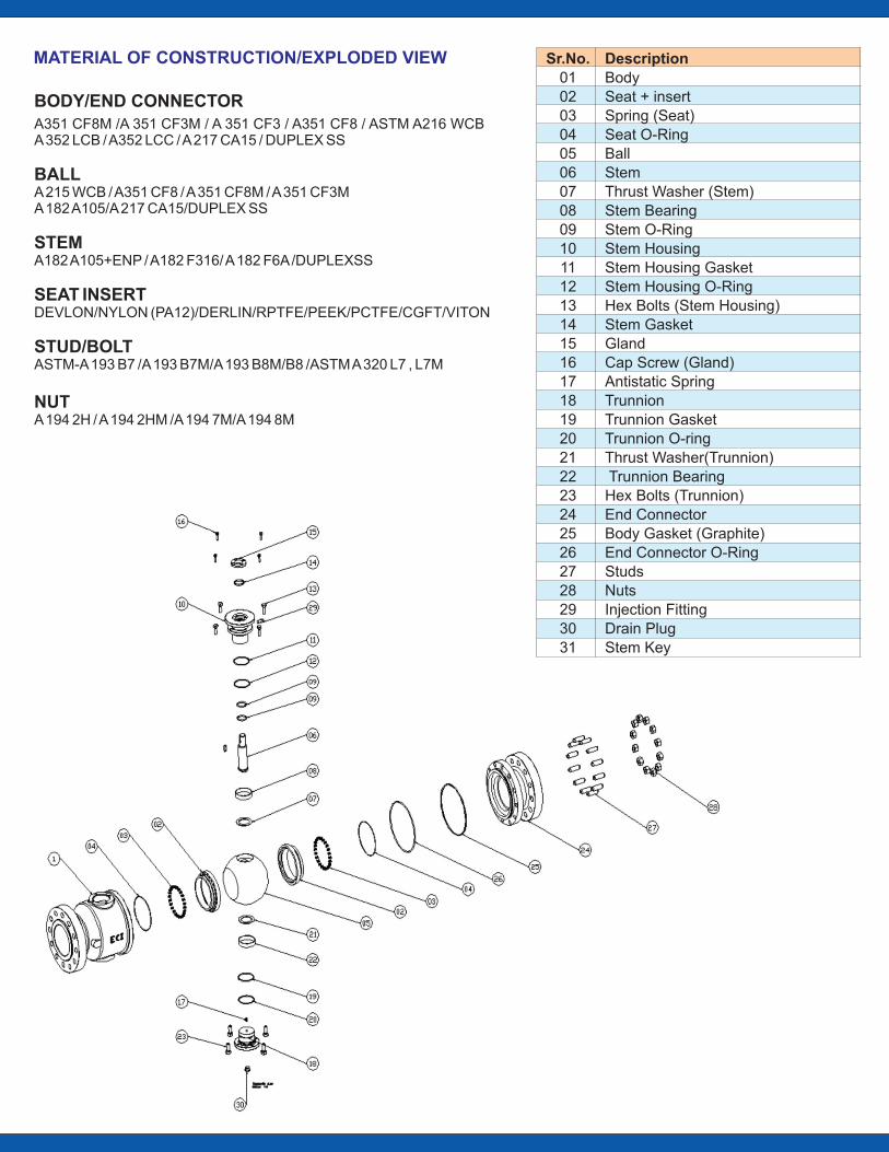
BODY/END CONNECTOR
A351 CF8M /A 351 CF3M / A 351 CF3 / A351 CF8 / ASTM A216 WCBA 352 LCB / A352 LCC / A 217 CA15 / DUPLEX SS
BALLA 215 WCB / A351 CF8 / A 351 CF8M / A 351 CF3MA 182 A105/A 217 CA15/DUPLEX SS
STEMA182 A105+ENP / A182 F316/ A 182 F6A /DUPLEXSS
SEAT INSERTDEVLON/NYLON (PA12)/DERLIN/RPTFE/PEEK/PCTFE/CGFT/VITON
STUD/BOLTASTM-A 193 B7 /A 193 B7M/A 193 B8M/B8 /ASTM A 320 L7 , L7M
NUTA 194 2H / A 194 2HM /A 194 7M/A 194 8M
MATERIAL OF CONSTRUCTION/EXPLODED VIEW DescriptionBodySeat + insertSpring (Seat)Seat O-RingBallStemThrust Washer (Stem)Stem BearingStem O-RingStem HousingStem Housing GasketStem Housing O-RingHex Bolts (Stem Housing)Stem GasketGlandCap Screw (Gland)Antistatic SpringTrunnionTrunnion GasketTrunnion O-ringThrust Washer(Trunnion) Trunnion BearingHex Bolts (Trunnion)End ConnectorBody Gasket (Graphite)End Connector O-RingStudsNutsInjection FittingDrain PlugStem Key
Sr.No.01020304050607080910111213141516171819202122232425262728293031
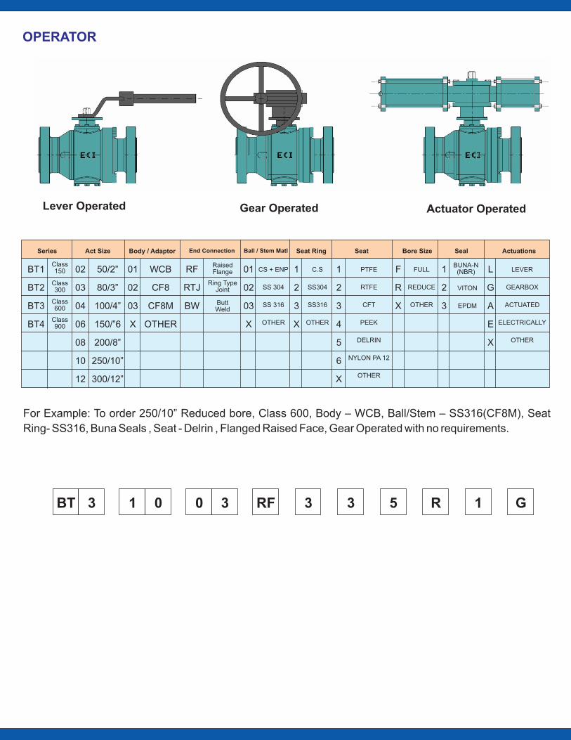
OPERATOR
Lever Operated Gear Operated Actuator Operated
50/2”
80/3”
100/4”
150/”6
200/8”
250/10”
300/12”
BT1
BT2
BT3
BT4
Class 150
Class 300
Class 600
Class 900
02
03
04
06
08
10
12
01
02
03
X
WCB
CF8
CF8M
OTHER
RF
RTJ
BW
01
02
03
X
1
2
3
X
Ring Type Joint
Raised Flange
Butt Weld
CS + ENP
SS 304
SS 316
OTHER
C.S
SS304
SS316
OTHER
1
2
3
4
5
6
X
PTFE
RTFE
CFT
PEEK
DELRIN
NYLON PA 12
OTHER
F
R
X
FULL
REDUCE
OTHER
1
2
3
L
G
A
E
X
LEVER
GEARBOX
ACTUATED
ELECTRICALLY
OTHER
VITON
EPDM
BUNA-N(NBR)
For Example: To order 250/10” Reduced bore, Class 600, Body – WCB, Ball/Stem – SS316(CF8M), Seat
Ring- SS316, Buna Seals , Seat - Delrin , Flanged Raised Face, Gear Operated with no requirements.
BT 3 1 0 RF0 3 3 3 5 R 1 G
SeatSeries Act Size Body / Adaptor Seat Ring Bore Size Seal ActuationsEnd Connection Ball / Stem Matl

Registered Office: 30, Shantiniketan (Air India) Co-op. Hsg. Society, 86, Yari Road, Versova, Mumbai - 400 061 India | Tel: +91 22 26363406 | E-mail: [email protected]
Nashik Works : 95/7, Road No. 19, MIDC, Satpur, Nashik - 422 007 | Maharashtra, IndiaTel: +91 253 2352773, Tel-Fax : 2360948 | E-mail: [email protected] | [email protected]
Mumbai Works :122, Guru Gobind Singh Indl. Estate, Western Express Highway, Goregaon (E), Mumbai - 400 063 | Maharashtra, India Tel: +91 22 26854196
E-mail: [email protected]
ENTECH CONTROLS
Recommended