GRUNDFOS DATA BOOKLET
SQ, SQ-N, SQE, SQE-NSubmersible pumps
50/60 Hz
Lenntech
[email protected] Tel. +31-152-610-900www.lenntech.com Fax. [email protected] Tel. +31-152-610-900www.lenntech.com Fax. +31-152-616-289
Lenntech
Ta
ble
of c
on
ten
ts
2
SQ, SQ-N, SQE, SQE-N
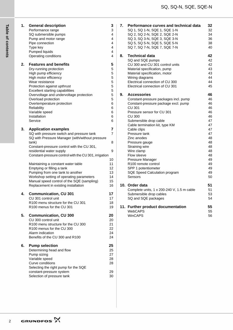
1. General description 3Performance range 3SQ submersible pumps 4Pump and motor range 4Pipe connection 4Type key 4Pumped liquids 4Operating conditions 4
2. Features and benefits 5Dry-running protection 5High pump efficiency 5High motor efficiency 5Wear resistance 5Protection against upthrust 5Excellent starting capabilities 5Overvoltage and undervoltage protection 5Overload protection 5Overtemperature protection 6Reliability 6Variable speed 6Installation 6Service 6
3. Application examples 7SQ with pressure switch and pressure tank 7SQ with Pressure Manager (with/without pressure tank) 8Constant-pressure control with the CU 301, residential water supply 9Constant-pressure control with the CU 301, irrigation
10Maintaining a constant water table 11Emptying or filling a tank 12Pumping from one tank to another 13Workshop setting of operating parameters 14Manual speed control of the SQE (sampling) 15Replacement in existing installation 16
4. Communication, CU 301 17CU 301 control unit 17R100 menu structure for the CU 301 18R100 menus for the CU 301 19
5. Communication, CU 300 20CU 300 control unit 20R100 menu structure for the CU 300 21R100 menus for the CU 300 22Alarm indication 24Benefits of the CU 300 and R100 24
6. Pump selection 25Determining head and flow 25Pump sizing 27Variable speed 28Curve conditions 28Selecting the right pump for the SQE constant-pressure system 29Selection of pressure tank 30
7. Performance curves and technical data 32SQ 1, SQ 1-N, SQE 1, SQE 1-N 32SQ 2, SQ 2-N, SQE 2, SQE 2-N 34SQ 3, SQ 3-N, SQE 3, SQE 3-N 36SQ 5, SQ 5-N, SQE 5, SQE 5-N 38SQ 7, SQ 7-N, SQE 7, SQE 7-N 40
8. Technical data 42SQ and SQE pumps 42CU 300 and CU 301 control units 42Material specification, pump 43Material specification, motor 43Wiring diagrams 44Electrical connection of CU 300 44Electrical connection of CU 301 45
9. Accessories 46Constant-pressure packages incl. pump 46Constant-pressure package excl. pump 46CU 301 46Pressure sensor for CU 301 46CU 300 46Submersible drop cable 47Cable termination kit, type KM 47Cable clips 47Pressure tank 47Zinc anodes 48Pressure gauge 48Straining wire 48Wire clamp 48Flow sleeve 48Pressure Manager 49R100 remote control 49SPP 1 potentiometer 49SQE Speed Calculation program 49Sensors 50
10. Order data 51Complete units, 1 x 200-240 V, 1.5 m cable 51Submersible drop cables 53SQ and SQE packages 54
11. Further product documentation 55WebCAPS 55WinCAPS 56
Ge
ne
ral
de
sc
rip
tio
n
SQ, SQ-N, SQE, SQE-N 1
1. General description
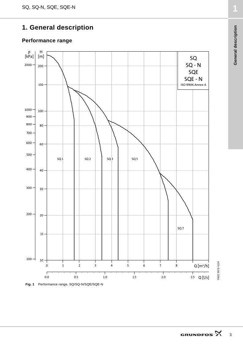
Performance range
Fig. 1 Performance range, SQ/SQ-N/SQE/SQE-N
TM
02
99
76
41
04
0 1 2 3 4 5 6 7 8 Q [m³/h]
10
15
20
30
40
60
80
100
150
200
H[m]
0.0 0.5 1.0 1.5 2.0 2.5 Q [l/s]
100100
200
300
400
500
600
700
800
900
10001000
2000
[kPa]p
SQ
SQE
ISO 9906 Annex A
SQ - N
SQE - N
SQ 1 SQ 2 SQ 3 SQ 5
SQ 7
3
Ge
ne
ral d
es
crip
tion
4
SQ, SQ-N, SQE, SQE-N1
SQ submersible pumpsSQ pumps are suitable for both continuous and intermittent operation for a variety of applications:
• domestic water supply
• small waterworks
• irrigation
• tank applications
• pressure boosting.
Note: For other applications, please contact Grundfos.
The SQ pump is a submersible pump which is available in four versions:
• SQ
• SQ-N
• SQE
• SQE-N.
SQ pumps offer the following features:
• dry-running protection
• high pump and motor efficiency
• wear resistance
• protection against upthrust
• soft starter
• overvoltage and undervoltage protection
• overload protection
• overtemperature protection.
Additionally the SQE pumps offer the following:
• variable speed
• electronic control and communication.
The motors are based on the most recent technology within permanent magnets. This technology is the main reason for the high efficiency of the motors. The motors have a built-in electronic unit containing a frequency converter featuring soft start.
The SQ pump is fitted with a single-phase Grundfos MS 3 or MS 3-NE motor, and by means of the built-in frequency converter it is driven at a constant speed.
The SQE pump is fitted with a single-phase Grundfos MSE 3 or MSE 3-NE motor. Both motor types can communicate with the Grundfos CU 300 and CU 301 control units, which can be operated with the Grundfos R100 remote control.
The SQE pump features variable speed which is offered through frequency control. This means that the pump can be set to operate in any duty point in the range between the pump min. and max. performance curves.
The CU 301 is specially developed for applications where a constant pressure is required.
The SQE pump can operate without the CU 300 or CU 301. However, in this situation it will not offer all the features available when the pump is connected to a CU 300 or CU 301. The CU 300 and CU 301 provide full control of the SQE pumps. In case of a pump fault, an alarm will be indicated on the front of the CU 300 or CU 301. The R100 enables monitoring of the installation and changing of the factory settings.
Pump and motor range
Pipe connection
Type key
Pumped liquidsSQ and SQE pumps are designed for pumping thin, clean, non-aggressive and non-explosive liquids, not containing solid particles or fibres. SQ and SQE are suitable for pumping liquids with a content of sand up to 50 g/m3. A higher content of sand will shorten pump life.
Operating conditions
Liquid temperature
Product Description Material
SQ pump (1, 2, 3, 5, and 7 m3/h)Stainless steelEN 1.4301, AISI 304
SQ-N pump (1, 2, 3, 5, and 7 m3/h)Stainless steelEN 1.4401, AISI 316
MS 3 motorSingle-phaseMax. 1.85 kW
Stainless steelEN 1.4301, AISI 304
MS 3-NE motorSingle-phaseMax. 1.85 kW
Stainless steelEN 1.4401, AISI 316
MSE 3 motorSingle-phaseMax. 1.85 kW
Stainless steelEN 1.4301, AISI 304
MSE 3-NE motorSingle-phaseMax. 1.85 kW
Stainless steelEN 1.4401, AISI 316
Pump type Threaded connection
SQ 1, SQ 2, SQ 3 Rp 1 1/4
SQ 5, SQ 7 Rp 1 1/2
Code Example SQ E 2 -55
Type range
EBasic versionElectronic control and communication
Rated flow [m3/h]
Head [m] at rated flow
N
Material code:Stainless steel EN 1.4301Stainless steel EN 1.4401
Flow velocity past motor Maximum liquid temperature
[°C]
0.0 m/s (free convection) 30
Min. 0.15 m/s 40
Fe
atu
res
an
d b
en
efi
ts
SQ, SQ-N, SQE, SQE-N 2
2. Features and benefits
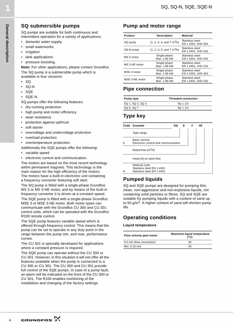
Dry-running protectionThe pumps are protected against dry running. A value of pcut-out ensures cut-out of the pump in case of water shortage in the borehole, thus preventing a burnout of the motor.
Pcut-out is factory-set both for the SQ and SQE pump.
Fig. 2 Dry-running protection
High pump efficiencyThe hydraulic pump components are polyamide-reinforced with 30 % glass fibre. The hydraulic design ensures high pump efficiency meaning low energy consumption and thus low energy costs.
High motor efficiencyThe motors are designed according to the permanent-magnet principle (PM motor) featuring high efficiency within a wide performance range.
Fig. 3 Comparison of motor efficiency
Wear resistanceThe pump impellers are not fastened to the shaft ("floating"). Each impeller has its own tungsten carbide/ceramic bearing. The design and the materials chosen ensure high wear resistance to sand and thus long product life.
Fig. 4 Impellers
Protection against upthrustStarting up a pump with a very low counter-pressure involves the risk of the entire impeller stack being lifted. This phenomenon is called upthrust. Upthrust may cause breakdown of both pump and motor.
The motors are fitted with an upthrust bearing protecting both pump and motor against upthrust and thus preventing breakdown during the critical start-up phase.
Excellent starting capabilitiesThe integrated electronic unit of the motor features soft starting. Soft starting reduces the starting current and thus gives the pump a smooth and steady acceleration.
The soft starter minimises the risk of wear of the pump and prevents overloading of the mains during start-up.
The excellent starting capabilities are a result of the high locked-rotor torque of the permanent-magnet motor together with the few pump stages. The high starting reliability also applies in case of low voltage supply.
Fig. 5 Comparison of locked-rotor current
Overvoltage and undervoltage protection Overvoltage and undervoltage may occur in case of unstable voltage supply.
The integrated protection of all motors prevents damage to the motor in case the voltage moves outside the permissible voltage range.
The pump will be cut out if the voltage falls below 150 V or rises above 315 V. The motor is automatically cut in again when the voltage is again within the permissible voltage range. Therefore no extra protection relay is required.
Overload protectionIf the pump is exposed to heavy load, the current consumption will rise. The motor will automatically compensate for this by reducing the speed. If the speed falls below 3000 min-1, the motor will be cut out.
If the rotor is being prevented from rotating, this will automatically be detected and the power supply will be cut out. Consequently, no extra motor protection is required.
TM
01
27
51
22
98
TM
01
26
98
22
98
TM
01
31
41
34
98
H
Qcut-out
P
Q
P1Pcut-out
200 250 300 350 400 450 500 550 P2 [W]
45
50
55
60
65
70
[%]Eta
Conventional 1 ph
Conventional 3 ph
MS 3
Conventional 3-ph.
Conventional 1-ph.
TM
01
34
79
41
98
Current [A]
DOL (direct-on-line starting)
Soft start
3 Time [s]
5
Fe
atu
res
an
d b
en
efits
6
SQ, SQ-N, SQE, SQE-N2
Overtemperature protectionA permanent-magnet motor gives off very little heat to its surroundings. In combination with an efficient internal circulation system leading the heat away from the rotor, stator and bearings, this ensures optimum operating conditions for the motor.
As an extra protection, the electronic unit has a built-in temperature sensor. When the temperature exceeds a critical limit, the motor is cut out. When the temperature has dropped, the motor is automatically cut in again.
ReliabilityThe motors have been designed with a view to high reliability and have the following features:
• tungsten carbide or ceramic bearings
• thrust bearings protecting against downthrust
• product life equal to conventional AC motors.
Variable speedThe MSE 3 motor enables continuously variable speed control within the range from 3,000 to 10,700 min-1. The pump can be set to operate in any duty point within the 3,000 and 10,700 min-1 performance range of the pump. Consequently, the pump performance can be adapted to any specific requirement.The variable-speed control facility requires the use of a CU 300 or CU 301 control unit and the R100 remote control. See page 28.
For the calculation of pump speed, the SQE Speed Calculation program is available on CD-ROM as an accessory. See page 49. On the basis of a required head and flow, the pump speed can be calculated. Furthermore, the specific pump performance curve can be illustrated.
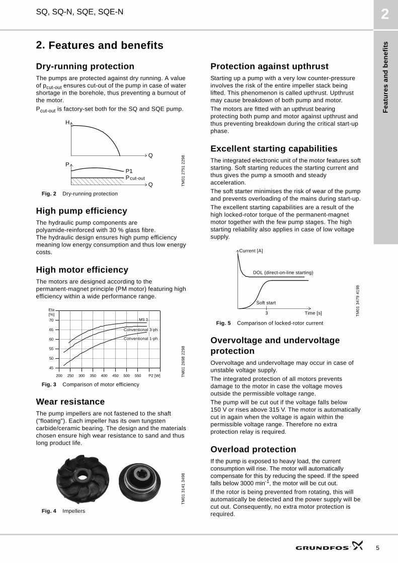
InstallationThe SQ and SQE may be installed vertically, horizontally or in any position in between.
Note: The pump must not fall below the horizontal level in relation to the motor.
Fig. 6 Installation of SQ/SQE pumps
The following features ensure simple installation of the pump:
• Built-in non-return valve with spring.
• Low weight ensuring user-friendly handling.
• Installation in 3" or larger boreholes.
• Only an on/off switch is required. This means that no extra motor starter or starter box is necessary.
• The SQE is available with cable with a motor plug (up to 100 m).
For horizontal installation, we recommend to install the pump in a flow sleeve.
The purpose is the following:
• to ensure sufficient flow velocity past the motor and thus provide sufficient cooling
• to prevent motor and electronic unit from being buried in sand or mud.
ServiceThe modular pump and motor design facilitates installation and service. The cable and plug are fitted to the pump with screws which enable replacement.
TM
01
13
75
14
98
Allowed
Not allowed
Ap
pli
ca
tio
n e
xa
mp
les
SQ, SQ-N, SQE, SQE-N 3
3. Application examples
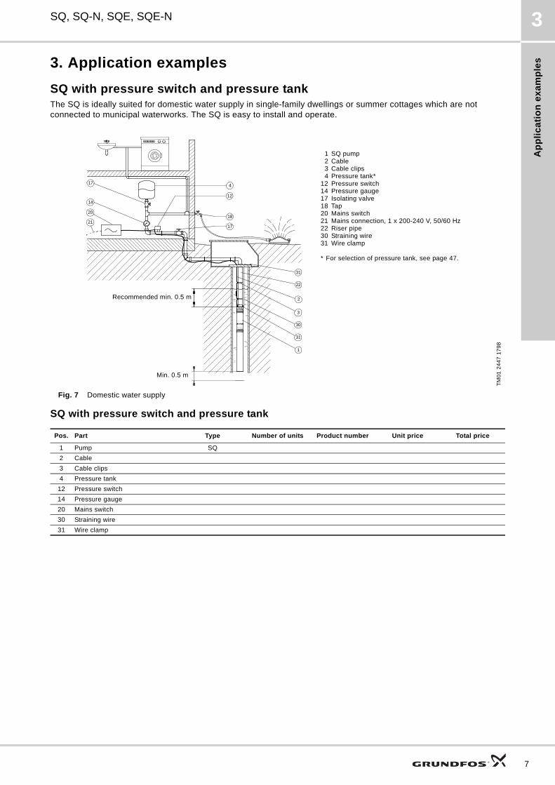
SQ with pressure switch and pressure tankThe SQ is ideally suited for domestic water supply in single-family dwellings or summer cottages which are not connected to municipal waterworks. The SQ is easy to install and operate.
Fig. 7 Domestic water supply
SQ with pressure switch and pressure tank
TM
01
24
47
17
98
17
14
22
2
3
4
12
1820
2117
31
30
31
1
1 SQ pump2 Cable3 Cable clips4 Pressure tank*
12 Pressure switch14 Pressure gauge17 Isolating valve18 Tap20 Mains switch21 Mains connection, 1 x 200-240 V, 50/60 Hz22 Riser pipe30 Straining wire31 Wire clamp
* For selection of pressure tank, see page 47.
Recommended min. 0.5 m
Min. 0.5 m
Pos. Part Type Number of units Product number Unit price Total price
1 Pump SQ
2 Cable
3 Cable clips
4 Pressure tank
12 Pressure switch
14 Pressure gauge
20 Mains switch
30 Straining wire
31 Wire clamp
7
Ap
plic
atio
n e
xa
mp
les
8
SQ, SQ-N, SQE, SQE-N3
SQ with Pressure Manager (with/without pressure tank)
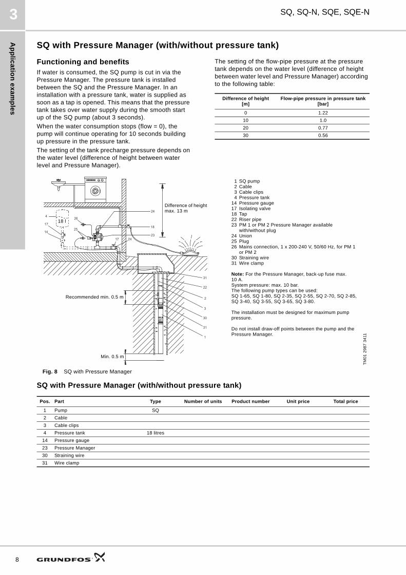
Functioning and benefitsIf water is consumed, the SQ pump is cut in via the Pressure Manager. The pressure tank is installed between the SQ and the Pressure Manager. In an installation with a pressure tank, water is supplied as soon as a tap is opened. This means that the pressure tank takes over water supply during the smooth start up of the SQ pump (about 3 seconds).
When the water consumption stops (flow = 0), the pump will continue operating for 10 seconds building up pressure in the pressure tank.
The setting of the tank precharge pressure depends on the water level (difference of height between water level and Pressure Manager).
The setting of the flow-pipe pressure at the pressure tank depends on the water level (difference of height between water level and Pressure Manager) according to the following table:
Fig. 8 SQ with Pressure Manager
SQ with Pressure Manager (with/without pressure tank)
Difference of height[m]
Flow-pipe pressure in pressure tank[bar]
0 1.22
10 1.0
20 0.77
30 0.56
TM
01
29
87
34
11
17
14
24
18
2317 24
26
25
4
22
2
3
31
30
31
1
1 SQ pump2 Cable3 Cable clips4 Pressure tank
14 Pressure gauge17 Isolating valve18 Tap22 Riser pipe23 PM 1 or PM 2 Pressure Manager available
with/without plug24 Union25 Plug26 Mains connection, 1 x 200-240 V, 50/60 Hz, for PM 1
or PM 230 Straining wire31 Wire clamp
Note: For the Pressure Manager, back-up fuse max. 10 A. System pressure: max. 10 bar.The following pump types can be used:SQ 1-65, SQ 1-80, SQ 2-35, SQ 2-55, SQ 2-70, SQ 2-85, SQ 3-40, SQ 3-55, SQ 3-65, SQ 3-80.
The installation must be designed for maximum pump pressure.
Do not install draw-off points between the pump and the Pressure Manager.
Recommended min. 0.5 m
Min. 0.5 m
Difference of height max. 13 m
18 l
Pos. Part Type Number of units Product number Unit price Total price
1 Pump SQ
2 Cable
3 Cable clips
4 Pressure tank 18 litres
14 Pressure gauge
23 Pressure Manager
30 Straining wire
31 Wire clamp
Ap
pli
ca
tio
n e
xa
mp
les
SQ, SQ-N, SQE, SQE-N 3
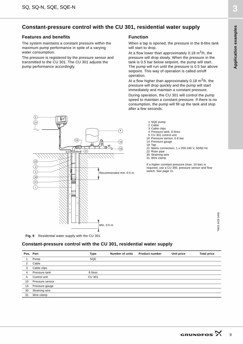
Constant-pressure control with the CU 301, residential water supply
Features and benefitsThe system maintains a constant pressure within the maximum pump performance in spite of a varying water consumption.
The pressure is registered by the pressure sensor and transmitted to the CU 301. The CU 301 adjusts the pump performance accordingly.
FunctionWhen a tap is opened, the pressure in the 8-litre tank will start to drop.
At a flow lower than approximately 0.18 m3/h, the pressure will drop slowly. When the pressure in the tank is 0.5 bar below setpoint, the pump will start. The pump will run until the pressure is 0.5 bar above setpoint. This way of operation is called on/off operation.
At a flow higher than approximately 0.18 m3/h, the pressure will drop quickly and the pump will start immediately and maintain a constant pressure.
During operation, the CU 301 will control the pump speed to maintain a constant pressure. If there is no consumption, the pump will fill up the tank and stop after a few seconds.
Fig. 9 Residential water supply with the CU 301
Constant-pressure control with the CU 301, residential water supply
TM
03
34
29
04
06
Pos. Part Type Number of units Product number Unit price Total price
1 Pump SQE
2 Cable
3 Cable clips
4 Pressure tank 8 litres
5 Control unit CU 301
10 Pressure sensor
14 Pressure gauge
30 Straining wire
31 Wire clamp
Recommended min. 0.5 m
Min. 0.5 m
1 SQE pump2 Cable3 Cable clips4 Pressure tank, 8 litres5 CU 301 control unit
10 Pressure sensor, 0-6 bar14 Pressure gauge18 Tap21 Mains connection, 1 x 200-240 V, 50/60 Hz22 Riser pipe30 Straining wire31 Wire clamp
If a higher constant pressure (max. 10 bar) is required, use a CU 300, pressure sensor and flow switch. See page 11.
9
Ap
plic
atio
n e
xa
mp
les
10
SQ, SQ-N, SQE, SQE-N3
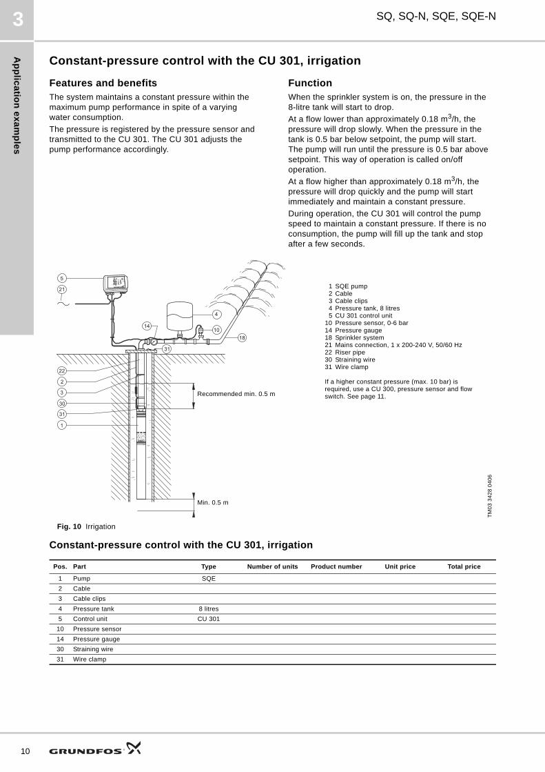
Constant-pressure control with the CU 301, irrigation
Features and benefitsThe system maintains a constant pressure within the maximum pump performance in spite of a varying water consumption.
The pressure is registered by the pressure sensor and transmitted to the CU 301. The CU 301 adjusts the pump performance accordingly.
FunctionWhen the sprinkler system is on, the pressure in the 8-litre tank will start to drop.
At a flow lower than approximately 0.18 m3/h, the pressure will drop slowly. When the pressure in the tank is 0.5 bar below setpoint, the pump will start. The pump will run until the pressure is 0.5 bar above setpoint. This way of operation is called on/off operation.
At a flow higher than approximately 0.18 m3/h, the pressure will drop quickly and the pump will start immediately and maintain a constant pressure.
During operation, the CU 301 will control the pump speed to maintain a constant pressure. If there is no consumption, the pump will fill up the tank and stop after a few seconds.
Fig. 10 Irrigation
Constant-pressure control with the CU 301, irrigation
TM
03
34
28
04
06
Pos. Part Type Number of units Product number Unit price Total price
1 Pump SQE
2 Cable
3 Cable clips
4 Pressure tank 8 litres
5 Control unit CU 301
10 Pressure sensor
14 Pressure gauge
30 Straining wire
31 Wire clamp
Min. 0.5 m
Recommended min. 0.5 m
1 SQE pump2 Cable3 Cable clips4 Pressure tank, 8 litres5 CU 301 control unit
10 Pressure sensor, 0-6 bar14 Pressure gauge18 Sprinkler system21 Mains connection, 1 x 200-240 V, 50/60 Hz22 Riser pipe30 Straining wire31 Wire clamp
If a higher constant pressure (max. 10 bar) is required, use a CU 300, pressure sensor and flow switch. See page 11.
Ap
pli
ca
tio
n e
xa
mp
les
SQ, SQ-N, SQE, SQE-N 3
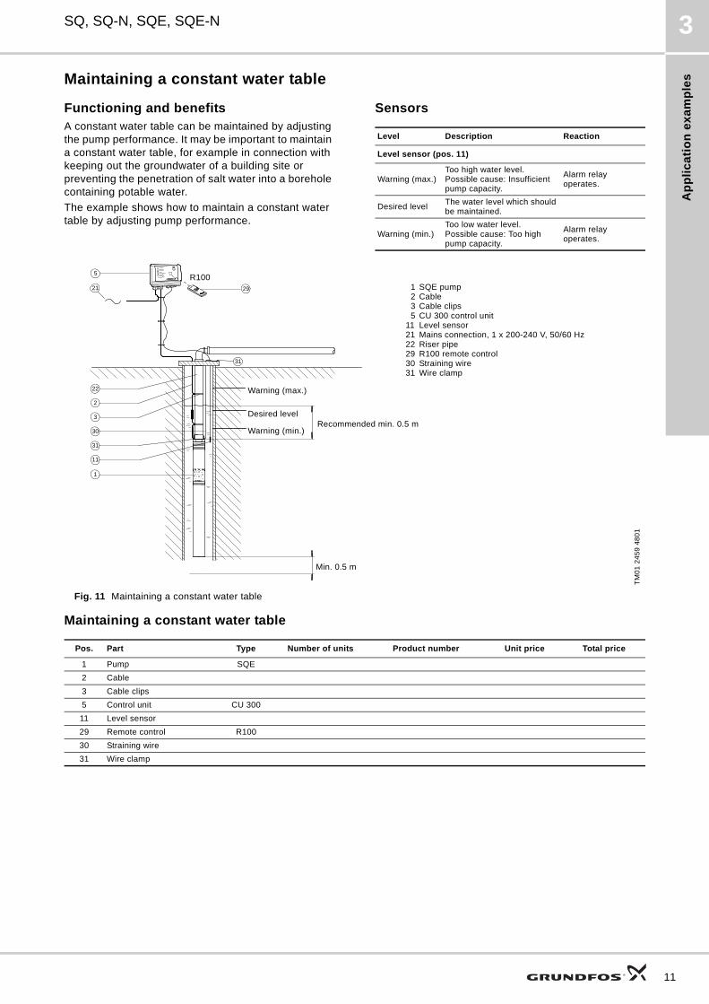
Maintaining a constant water table
Functioning and benefitsA constant water table can be maintained by adjusting the pump performance. It may be important to maintain a constant water table, for example in connection with keeping out the groundwater of a building site or preventing the penetration of salt water into a borehole containing potable water.
The example shows how to maintain a constant water table by adjusting pump performance.
Sensors
Fig. 11 Maintaining a constant water table
Maintaining a constant water table
Level Description Reaction
Level sensor (pos. 11)
Warning (max.)Too high water level. Possible cause: Insufficient pump capacity.
Alarm relay operates.
Desired levelThe water level which should be maintained.
Warning (min.)Too low water level. Possible cause: Too high pump capacity.
Alarm relay operates.
TM
01
24
59
48
01
22
31
2
3
30
31
11
R1005
21 29
1
1 SQE pump2 Cable3 Cable clips5 CU 300 control unit
11 Level sensor21 Mains connection, 1 x 200-240 V, 50/60 Hz22 Riser pipe29 R100 remote control30 Straining wire31 Wire clamp
R100
Warning (max.)
Desired level
Warning (min.)Recommended min. 0.5 m
Min. 0.5 m
Pos. Part Type Number of units Product number Unit price Total price
1 Pump SQE
2 Cable
3 Cable clips
5 Control unit CU 300
11 Level sensor
29 Remote control R100
30 Straining wire
31 Wire clamp
11
Ap
plic
atio
n e
xa
mp
les
12
SQ, SQ-N, SQE, SQE-N3
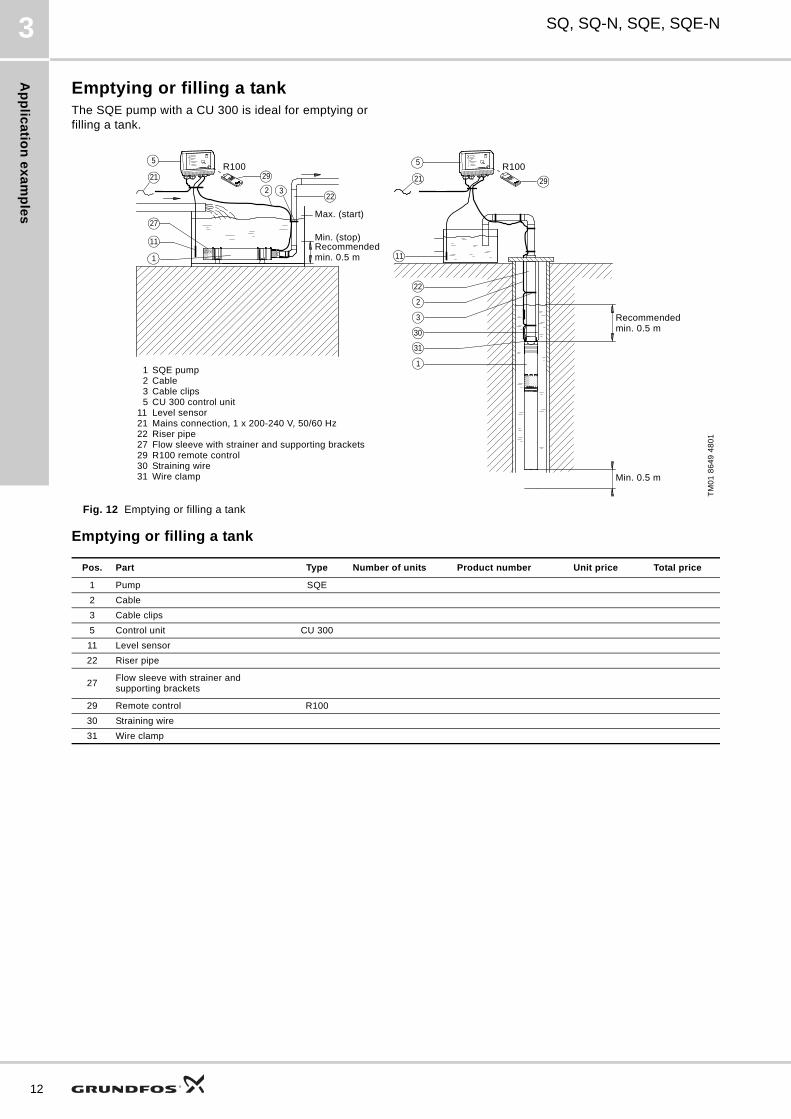
Emptying or filling a tankThe SQE pump with a CU 300 is ideal for emptying or filling a tank.
Fig. 12 Emptying or filling a tank
Emptying or filling a tank
TM
01
86
49
48
01
Pos. Part Type Number of units Product number Unit price Total price
1 Pump SQE
2 Cable
3 Cable clips
5 Control unit CU 300
11 Level sensor
22 Riser pipe
27Flow sleeve with strainer and supporting brackets
29 Remote control R100
30 Straining wire
31 Wire clamp
22
29
2
3
30
1
31
29
R100
2232
5
21
27
11
1
5
21R100
11
Min. 0.5 m
Recommended min. 0.5 m
1 SQE pump2 Cable3 Cable clips5 CU 300 control unit
11 Level sensor21 Mains connection, 1 x 200-240 V, 50/60 Hz22 Riser pipe27 Flow sleeve with strainer and supporting brackets29 R100 remote control 30 Straining wire31 Wire clamp
R100 R100
Max. (start)
Min. (stop)Recommended min. 0.5 m
Ap
pli
ca
tio
n e
xa
mp
les
SQ, SQ-N, SQE, SQE-N 3
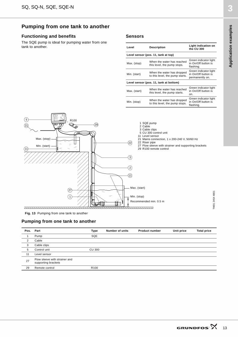
Pumping from one tank to another
Functioning and benefitsThe SQE pump is ideal for pumping water from one tank to another.
Sensors
Fig. 13 Pumping from one tank to another
Pumping from one tank to another
Level DescriptionLight indication on the CU 300
Level sensor (pos. 11, tank at top)
Max. (stop)When the water has reached this level, the pump stops.
Green indicator light in On/Off button is flashing.
Min. (start)When the water has dropped to this level, the pump starts.
Green indicator light in On/Off button is permanently on.
Level sensor (pos. 11, tank at bottom)
Max. (start)When the water has reached this level, the pump starts.
Green indicator light in On/Off button is on.
Min. (stop)When the water has dropped to this level, the pump stops.
Green indicator light in On/Off button is flashing.
TM
01
24
54
48
01
Pos. Part Type Number of units Product number Unit price Total price
1 Pump SQE
2 Cable
3 Cable clips
5 Control unit CU 300
11 Level sensor
27Flow sleeve with strainer and supporting brackets
29 Remote control R100
22
3
2
1
27
11
21
5
11
R10029 1 SQE pump
2 Cable3 Cable clips5 CU 300 control unit
11 Level sensor21 Mains connection, 1 x 200-240 V, 50/60 Hz22 Riser pipe27 Flow sleeve with strainer and supporting brackets29 R100 remote control
R100
Max. (start)
Min. (stop)
Recommended min. 0.5 m
Max. (stop)
Min. (start)
13
Ap
plic
atio
n e
xa
mp
les
14
SQ, SQ-N, SQE, SQE-N3
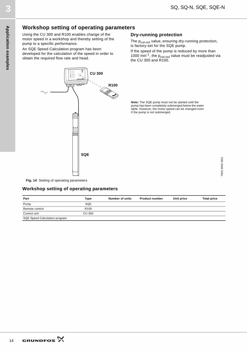
Workshop setting of operating parametersUsing the CU 300 and R100 enables change of the motor speed in a workshop and thereby setting of the pump to a specific performance.
An SQE Speed Calculation program has been developed for the calculation of the speed in order to obtain the required flow rate and head.
Dry-running protectionThe pcut-out value, ensuring dry-running protection, is factory-set for the SQE pump.
If the speed of the pump is reduced by more than 1000 min-1, the pcut-out value must be readjusted via the CU 300 and R100.
Fig. 14 Setting of operating parameters
Workshop setting of operating parameters
TM
01
86
50
48
01
Part Type Number of units Product number Unit price Total price
Pump SQE
Remote control R100
Control unit CU 300
SQE Speed Calculation program
Note: The SQE pump must not be started until the pump has been completely submerged below the water table. However, the motor speed can be changed even if the pump is not submerged.
R100
CU 300
SQE
Ap
pli
ca
tio
n e
xa
mp
les
SQ, SQ-N, SQE, SQE-N 3
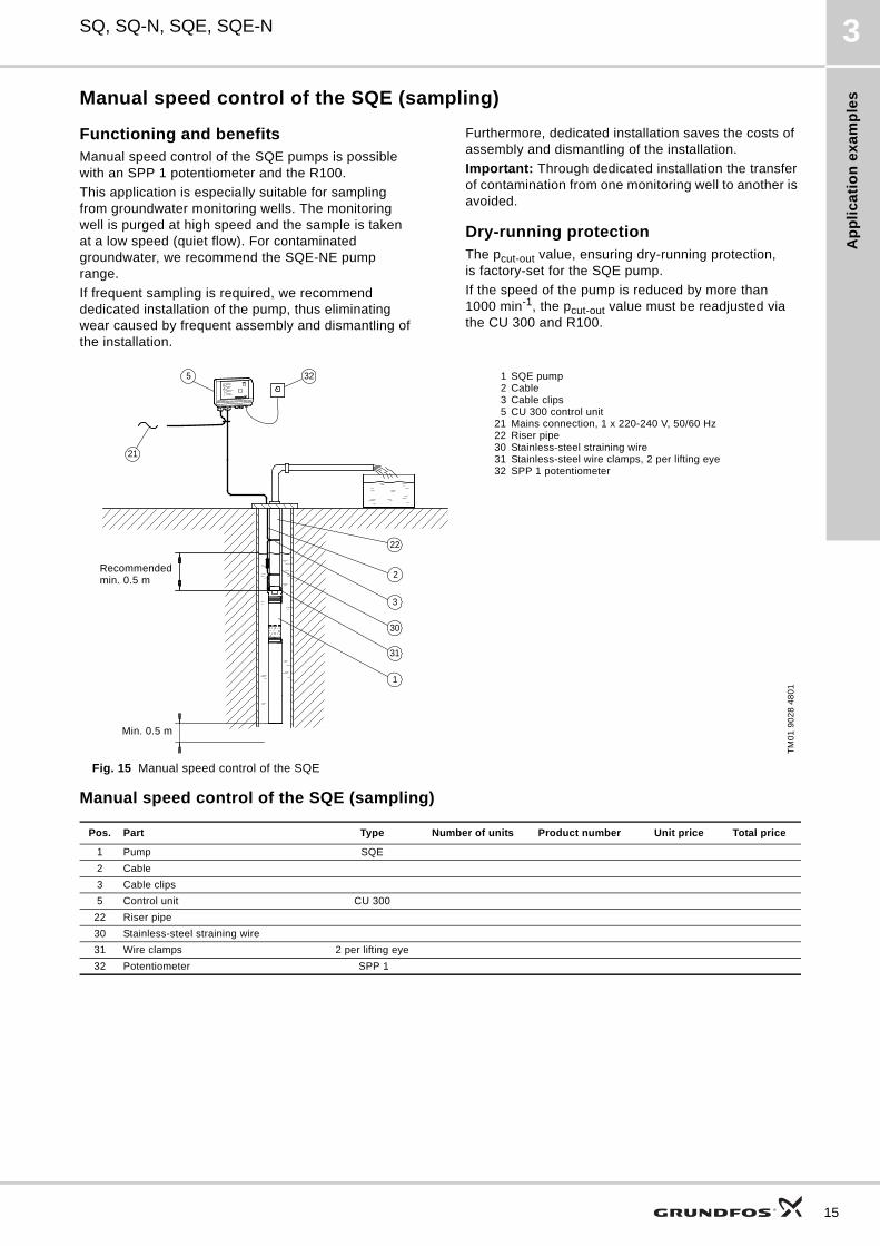
Manual speed control of the SQE (sampling)
Functioning and benefitsManual speed control of the SQE pumps is possible with an SPP 1 potentiometer and the R100.
This application is especially suitable for sampling from groundwater monitoring wells. The monitoring well is purged at high speed and the sample is taken at a low speed (quiet flow). For contaminated groundwater, we recommend the SQE-NE pump range.
If frequent sampling is required, we recommend dedicated installation of the pump, thus eliminating wear caused by frequent assembly and dismantling of the installation.
Furthermore, dedicated installation saves the costs of assembly and dismantling of the installation.
Important: Through dedicated installation the transfer of contamination from one monitoring well to another is avoided.
Dry-running protectionThe pcut-out value, ensuring dry-running protection, is factory-set for the SQE pump.
If the speed of the pump is reduced by more than 1000 min-1, the pcut-out value must be readjusted via the CU 300 and R100.
Fig. 15 Manual speed control of the SQE
Manual speed control of the SQE (sampling)T
M0
1 9
02
8 4
80
1
21
325
22
2
3
31
1
30
1 SQE pump2 Cable3 Cable clips5 CU 300 control unit
21 Mains connection, 1 x 220-240 V, 50/60 Hz22 Riser pipe30 Stainless-steel straining wire31 Stainless-steel wire clamps, 2 per lifting eye32 SPP 1 potentiometer
Recommended min. 0.5 m
Min. 0.5 m
Pos. Part Type Number of units Product number Unit price Total price
1 Pump SQE
2 Cable
3 Cable clips
5 Control unit CU 300
22 Riser pipe
30 Stainless-steel straining wire
31 Wire clamps 2 per lifting eye
32 Potentiometer SPP 1
15
Ap
plic
atio
n e
xa
mp
les
16
SQ, SQ-N, SQE, SQE-N3
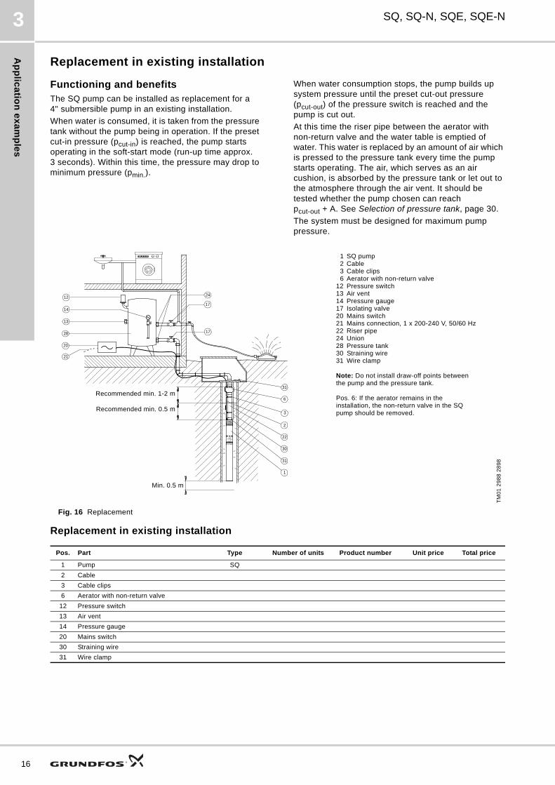
Replacement in existing installation
Functioning and benefitsThe SQ pump can be installed as replacement for a 4" submersible pump in an existing installation.
When water is consumed, it is taken from the pressure tank without the pump being in operation. If the preset cut-in pressure (pcut-in) is reached, the pump starts operating in the soft-start mode (run-up time approx. 3 seconds). Within this time, the pressure may drop to minimum pressure (pmin.).
When water consumption stops, the pump builds up system pressure until the preset cut-out pressure (pcut-out) of the pressure switch is reached and the pump is cut out.
At this time the riser pipe between the aerator with non-return valve and the water table is emptied of water. This water is replaced by an amount of air which is pressed to the pressure tank every time the pump starts operating. The air, which serves as an air cushion, is absorbed by the pressure tank or let out to the atmosphere through the air vent. It should be tested whether the pump chosen can reach pcut-out + A. See Selection of pressure tank, page 30.
The system must be designed for maximum pump pressure.
Fig. 16 Replacement
Replacement in existing installation
TM
01
29
88
28
98
Pos. Part Type Number of units Product number Unit price Total price
1 Pump SQ
2 Cable
3 Cable clips
6 Aerator with non-return valve
12 Pressure switch
13 Air vent
14 Pressure gauge
20 Mains switch
30 Straining wire
31 Wire clamp
6
3
2
31
22
30
14
21
17
17
2412
31
28
20
1
13
1 SQ pump2 Cable3 Cable clips6 Aerator with non-return valve
12 Pressure switch13 Air vent14 Pressure gauge17 Isolating valve20 Mains switch21 Mains connection, 1 x 200-240 V, 50/60 Hz22 Riser pipe24 Union28 Pressure tank30 Straining wire31 Wire clamp
Note: Do not install draw-off points between the pump and the pressure tank.
Pos. 6: If the aerator remains in the installation, the non-return valve in the SQ pump should be removed.
Min. 0.5 m
Recommended min. 0.5 m
Recommended min. 1-2 m
Co
mm
un
ica
tio
n,
CU
30
1
SQ, SQ-N, SQE, SQE-N 4
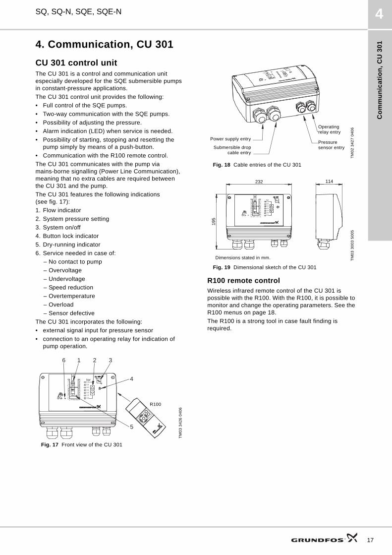
4. Communication, CU 301
CU 301 control unitThe CU 301 is a control and communication unit especially developed for the SQE submersible pumps in constant-pressure applications.
The CU 301 control unit provides the following:
• Full control of the SQE pumps.
• Two-way communication with the SQE pumps.
• Possibility of adjusting the pressure.
• Alarm indication (LED) when service is needed.
• Possibility of starting, stopping and resetting the pump simply by means of a push-button.
• Communication with the R100 remote control.
The CU 301 communicates with the pump via mains-borne signalling (Power Line Communication), meaning that no extra cables are required between the CU 301 and the pump.
The CU 301 features the following indications (see fig. 17):
1. Flow indicator
2. System pressure setting
3. System on/off
4. Button lock indicator
5. Dry-running indicator
6. Service needed in case of:
– No contact to pump
– Overvoltage
– Undervoltage
– Speed reduction
– Overtemperature
– Overload
– Sensor defective
The CU 301 incorporates the following:
• external signal input for pressure sensor
• connection to an operating relay for indication of pump operation.
Fig. 17 Front view of the CU 301
Fig. 18 Cable entries of the CU 301
Fig. 19 Dimensional sketch of the CU 301
R100 remote controlWireless infrared remote control of the CU 301 is possible with the R100. With the R100, it is possible to monitor and change the operating parameters. See the R100 menus on page 18.
The R100 is a strong tool in case fault finding is required.
TM
03
34
26
04
06
bar5.0
4.5
4.0
3.5
3.0
2.5
2.0
2 3
4
1
5
6
R 100R100
TM
02
34
27
04
06
TM
03
30
03
50
05
Pressure sensor entry
Power supply entry
Submersible dropcable entry
Operating relay entry
Dimensions stated in mm.
232 114
195
bar5.0
4.54.0
3.53.0
2.5
2.0
17
Co
mm
un
ica
tion
, CU
30
1
18
SQ, SQ-N, SQE, SQE-N4
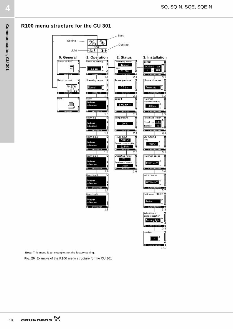
R100 menu structure for the CU 301
Fig. 20 Example of the R100 menu structure for the CU 301
Note: This menu is an example, not the factory setting.
Start
Contrast
Setting
Light
0. General 1. Operation 2. Status 3. Installation
1.1
1.2
1.3
1.4
1.5
1.6
1.7
1.8
2.1
2.2
2.3
2.4
2.5
2.6
3.1
3.2
3.3
3.4
3.5
3.6
3.7
3.8
3.9
3.10
Co
mm
un
ica
tio
n,
CU
30
1
SQ, SQ-N, SQE, SQE-N 4
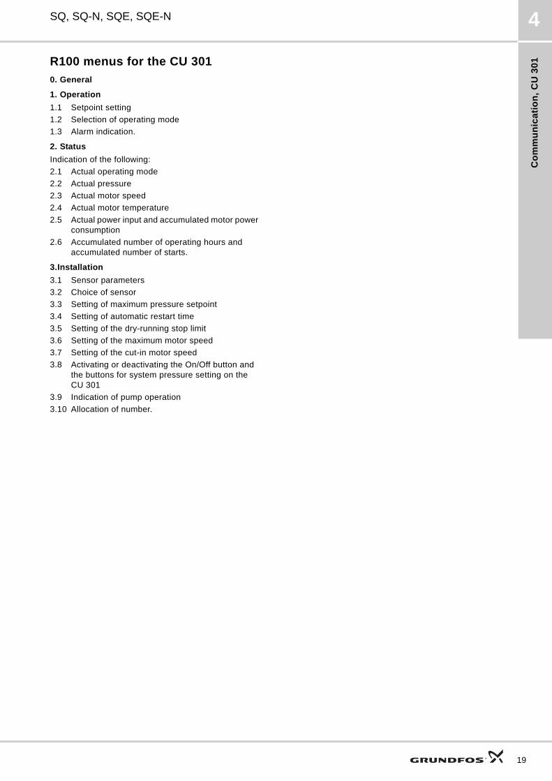
R100 menus for the CU 301
0. General
1. Operation
1.1 Setpoint setting
1.2 Selection of operating mode
1.3 Alarm indication.
2. Status
Indication of the following:
2.1 Actual operating mode
2.2 Actual pressure
2.3 Actual motor speed
2.4 Actual motor temperature
2.5 Actual power input and accumulated motor power consumption
2.6 Accumulated number of operating hours and accumulated number of starts.
3.Installation
3.1 Sensor parameters
3.2 Choice of sensor
3.3 Setting of maximum pressure setpoint
3.4 Setting of automatic restart time
3.5 Setting of the dry-running stop limit
3.6 Setting of the maximum motor speed
3.7 Setting of the cut-in motor speed
3.8 Activating or deactivating the On/Off button and the buttons for system pressure setting on the CU 301
3.9 Indication of pump operation
3.10 Allocation of number.
19
Co
mm
un
ica
tion
, CU
30
0
20
SQ, SQ-N, SQE, SQE-N5
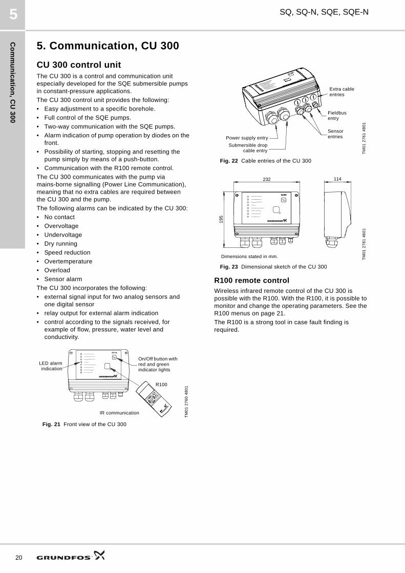
5. Communication, CU 300
CU 300 control unitThe CU 300 is a control and communication unit especially developed for the SQE submersible pumps in constant-pressure applications.
The CU 300 control unit provides the following:
• Easy adjustment to a specific borehole.
• Full control of the SQE pumps.
• Two-way communication with the SQE pumps.
• Alarm indication of pump operation by diodes on the front.
• Possibility of starting, stopping and resetting the pump simply by means of a push-button.
• Communication with the R100 remote control.
The CU 300 communicates with the pump via mains-borne signalling (Power Line Communication), meaning that no extra cables are required between the CU 300 and the pump.
The following alarms can be indicated by the CU 300:
• No contact
• Overvoltage
• Undervoltage
• Dry running
• Speed reduction
• Overtemperature
• Overload
• Sensor alarm
The CU 300 incorporates the following:
• external signal input for two analog sensors and one digital sensor
• relay output for external alarm indication
• control according to the signals received, for example of flow, pressure, water level and conductivity.
Fig. 21 Front view of the CU 300
Fig. 22 Cable entries of the CU 300
Fig. 23 Dimensional sketch of the CU 300
R100 remote controlWireless infrared remote control of the CU 300 is possible with the R100. With the R100, it is possible to monitor and change the operating parameters. See the R100 menus on page 21.
The R100 is a strong tool in case fault finding is required.
TM
01
27
60
48
01
LED alarmindication
On/Off button with red and green indicator lights
IR communication
R100
TM
01
27
61
48
01
TM
01
27
81
46
01
Power supply entry
Submersible dropcable entry
Extra cable entries
Fieldbus entry
Sensor entries
Dimensions stated in mm.
232 114
195
Co
mm
un
ica
tio
n,
CU
30
0
SQ, SQ-N, SQE, SQE-N 5
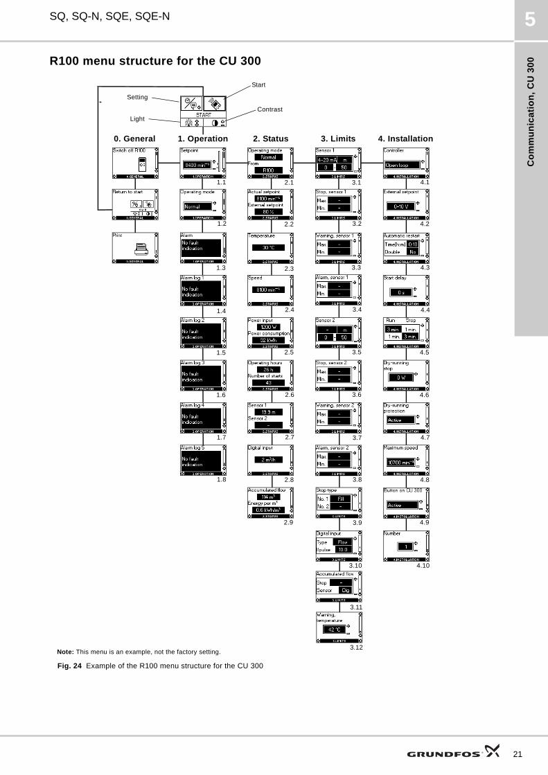
R100 menu structure for the CU 300
Fig. 24 Example of the R100 menu structure for the CU 300
Start
Contrast
Setting
Light
0. General 1. Operation 2. Status 4. Installation3. Limits
Note: This menu is an example, not the factory setting.
1.1
1.2
1.3
1.4
1.5
1.6
1.7
1.8
2.1
2.2
2.3
2.4
2.5
2.6
2.7
2.8
3.1 4.1
3.2 4.2
3.3 4.3
3.4 4.4
3.5 4.5
3.6 4.6
3.7 4.7
3.8 4.8
3.9 4.9
4.103.10
3.11
3.12
2.9
21
Co
mm
un
ica
tion
, CU
30
0
22
SQ, SQ-N, SQE, SQE-N5
R100 menus for the CU 300
0. General
1. Operation
1.1 Setpoint setting
1.2 Selection of operating mode
1.3 Alarm indication.
2. Status
Indication of the following:
2.1 Actual operating mode
2.2 Actual and external setpoint
2.3 Actual motor temperature
2.4 Actual motor speed
2.5 Actual power input and accumulated motor power consumption
2.6 Accumulated number of operating hours and accumulated number of starts
2.7 Actual values of sensors 1 and 2, respectively
2.8 Actual values of the digital input
2.9 Accumulated flow, and the power used to pump 1 m3.
The R100 offers the possibility of making a number of settings.
3. Limits
Setting of the following:
3.1 Sensor 1 parameters
3.2 Min. and max. stop limits of sensor 1
3.3 Min. and max. warning limits of sensor 1
3.4 Min. and max. alarm limits of sensor 1
3.5 Sensor 2 parameters
3.6 Min. and max. stop limits of sensor 2
3.7 Min. and max. warning limits of sensor 2
3.8 Min. and max. alarm limits of sensor 2
3.9 Filling or emptying
3.10 Setting of the function of the digital sensor connected to the digital input
3.11 Setting of the water quantity stop limit and the setting of the sensor to detect water quantity
3.12 Setting of the temperature warning limits of the motor electronics.
4. Installation
4.1 Selection of controller
4.2 Setting of external setpoint
4.3 Setting of automatic restart time
4.4 Allocation of individual start delays
4.5 Setting of the stop and run times for the dewatering function
4.6 Setting of the dry-running stop limit
4.7 Activating or deactivating the dry-running protection
4.8 Setting of the maximum motor speed
4.9 Activating or deactivating the On/Off button on the CU 300
4.10 Allocation of number where more than one CU 300 is installed.
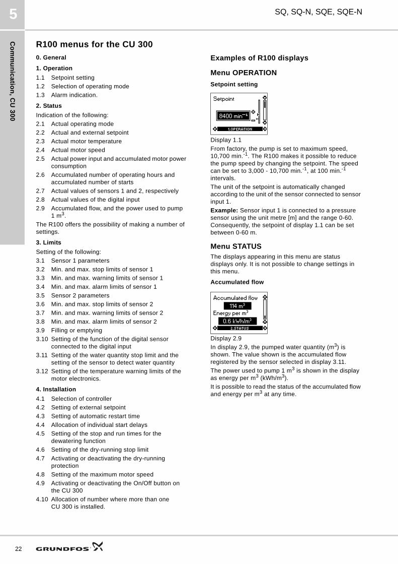
Examples of R100 displays
Menu OPERATION
Setpoint setting
Display 1.1
From factory, the pump is set to maximum speed, 10,700 min.-1. The R100 makes it possible to reduce the pump speed by changing the setpoint. The speed can be set to 3,000 - 10,700 min.-1, at 100 min.-1 intervals.
The unit of the setpoint is automatically changed according to the unit of the sensor connected to sensor input 1.
Example: Sensor input 1 is connected to a pressure sensor using the unit metre [m] and the range 0-60. Consequently, the setpoint of display 1.1 can be set between 0-60 m.
Menu STATUSThe displays appearing in this menu are status displays only. It is not possible to change settings in this menu.
Accumulated flow
Display 2.9
In display 2.9, the pumped water quantity (m3) is shown. The value shown is the accumulated flow registered by the sensor selected in display 3.11.
The power used to pump 1 m3 is shown in the display as energy per m3 (kWh/m3).
It is possible to read the status of the accumulated flow and energy per m3 at any time.
Co
mm
un
ica
tio
n,
CU
30
0
SQ, SQ-N, SQE, SQE-N 5
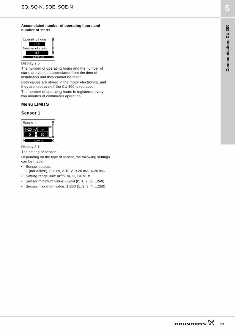
Accumulated number of operating hours and number of starts
Display 2.6
The number of operating hours and the number of starts are values accumulated from the time of installation and they cannot be reset.
Both values are stored in the motor electronics, and they are kept even if the CU 300 is replaced.
The number of operating hours is registered every two minutes of continuous operation.
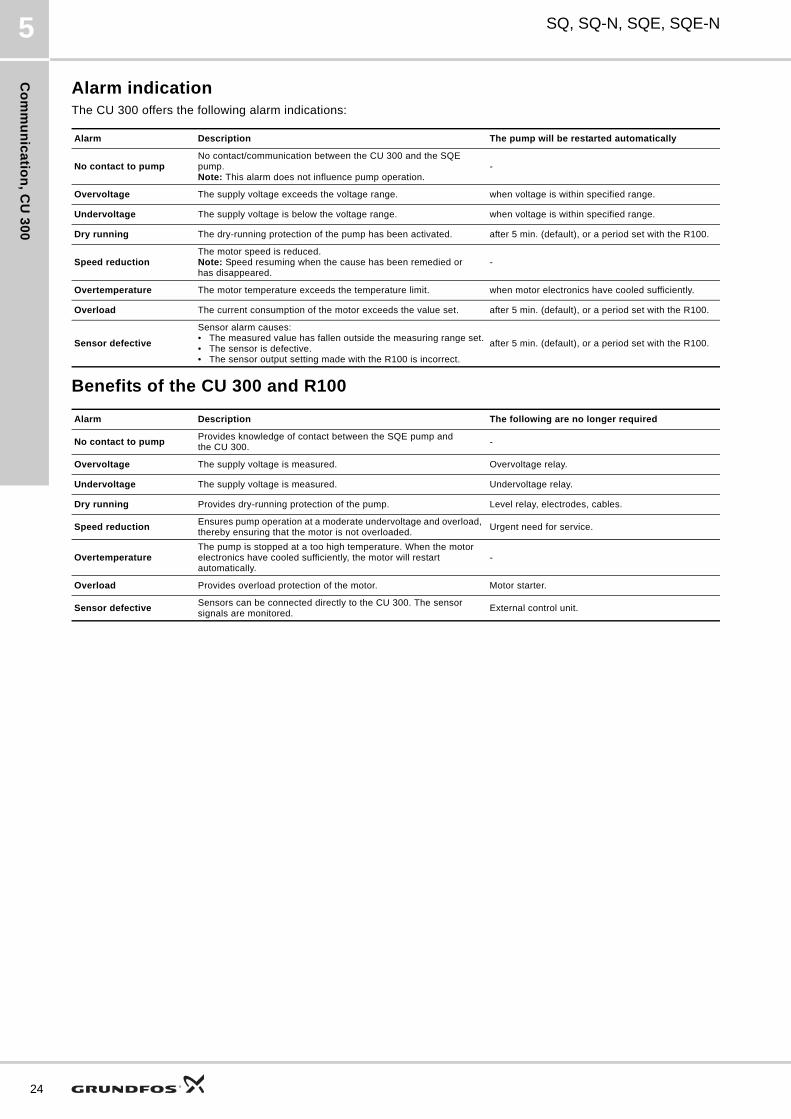
Menu LIMITS
Sensor 1
Display 3.1
The setting of sensor 1.
Depending on the type of sensor, the following settings can be made:
• Sensor outputs:– (not active), 0-10 V, 2-10 V, 0-20 mA, 4-20 mA.
• Setting range unit: m3/h, m, %, GPM, ft.
• Sensor minimum value: 0-249 (0, 1, 2, 3.....249).
• Sensor maximum value: 1-250 (1, 2, 3, 4.....250).
23
Co
mm
un
ica
tion
, CU
30
0
24
SQ, SQ-N, SQE, SQE-N5
Alarm indicationThe CU 300 offers the following alarm indications:
Benefits of the CU 300 and R100
Alarm Description The pump will be restarted automatically
No contact to pumpNo contact/communication between the CU 300 and the SQE pump. Note: This alarm does not influence pump operation.
-
Overvoltage The supply voltage exceeds the voltage range. when voltage is within specified range.
Undervoltage The supply voltage is below the voltage range. when voltage is within specified range.
Dry running The dry-running protection of the pump has been activated. after 5 min. (default), or a period set with the R100.
Speed reductionThe motor speed is reduced. Note: Speed resuming when the cause has been remedied or has disappeared.
-
Overtemperature The motor temperature exceeds the temperature limit. when motor electronics have cooled sufficiently.
Overload The current consumption of the motor exceeds the value set. after 5 min. (default), or a period set with the R100.
Sensor defective
Sensor alarm causes: • The measured value has fallen outside the measuring range set.• The sensor is defective.• The sensor output setting made with the R100 is incorrect.
after 5 min. (default), or a period set with the R100.
Alarm Description The following are no longer required
No contact to pumpProvides knowledge of contact between the SQE pump and the CU 300.
-
Overvoltage The supply voltage is measured. Overvoltage relay.
Undervoltage The supply voltage is measured. Undervoltage relay.
Dry running Provides dry-running protection of the pump. Level relay, electrodes, cables.
Speed reductionEnsures pump operation at a moderate undervoltage and overload, thereby ensuring that the motor is not overloaded.
Urgent need for service.
OvertemperatureThe pump is stopped at a too high temperature. When the motor electronics have cooled sufficiently, the motor will restart automatically.
-
Overload Provides overload protection of the motor. Motor starter.
Sensor defectiveSensors can be connected directly to the CU 300. The sensor signals are monitored.
External control unit.
Pu
mp
se
lec
tio
n
SQ, SQ-N, SQE, SQE-N 6
6. Pump selection
Determining head and flowPump selection is based on the water demand and the required head.
Water demandThe manufacturers of fittings and sprinkler systems normally state this data.
Examples of water demand:
Sprinkler systems: 1.5 m3/h per sprinkler
Domestic water supply: 2-4 m3/h
Agriculture: 4-6 m3/h
Irrigation: 6-8 m3/h
Head
For selection of Hf, see Head losses (Hf) in plastic pipes and ordinary water pipes, page 26.
Example of calculation
Application: Domestic water supply.
Required flow: 2.4 m3/h
ptap = 3 bar
Hgeo = 30 m
Hf = 7.7 m
The tubing is made of plastic pipe, 25, length 35 m.
This will give the following:
Hf = value from table x length of pipe
Hf = 0.22 x 35 m = 7.7 m
H [m] = ptap x 10.2 + Hgeo + Hf
= 3 x 10.2 + 30 m + 7.7 = 68.3 m
Selected at Q = 2.4 m3/h, H = 68.3 m
For selection of the pump type best meeting the requirements, see Pump sizing, page 27.
H [m] = ptap x 10.2 + Hgeo + Hf
ptap = required pressure at the draw-off point (for example sprinkler), at least 2 bar.
Hgeo = difference of height between lower water level in well and draw-off point.
Hf = loss of head in piping and tubing.
25
Pu
mp
se
lec
tion
26
SQ, SQ-N, SQE, SQE-N6
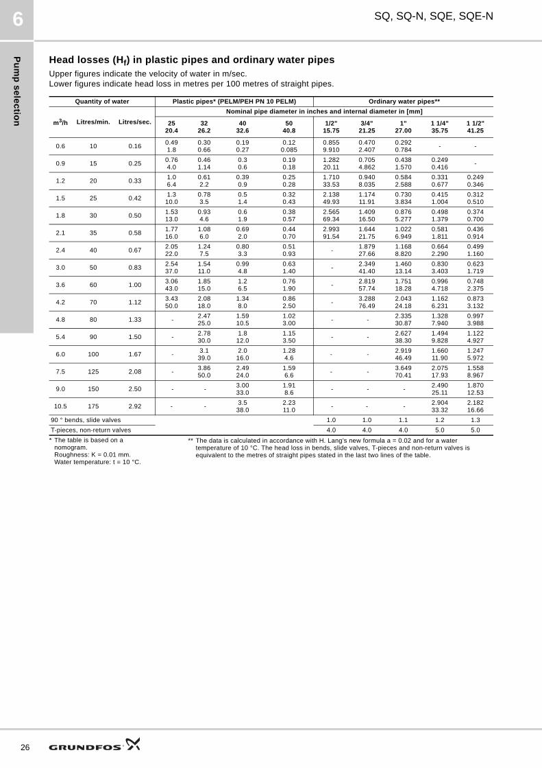
Head losses (Hf) in plastic pipes and ordinary water pipesUpper figures indicate the velocity of water in m/sec.Lower figures indicate head loss in metres per 100 metres of straight pipes.
Quantity of water Plastic pipes* (PELM/PEH PN 10 PELM) Ordinary water pipes**
m3/h Litres/min. Litres/sec.
Nominal pipe diameter in inches and internal diameter in [mm]
2520.4
3226.2
4032.6
5040.8
1/2"15.75
3/4"21.25
1"27.00
1 1/4"35.75
1 1/2"41.25
0.6 10 0.16 0.491.8
0.300.66
0.190.27
0.120.085
0.8559.910
0.4702.407
0.2920.784
- -
0.9 15 0.25 0.764.0
0.461.14
0.30.6
0.190.18
1.28220.11
0.7054.862
0.4381.570
0.2490.416
-
1.2 20 0.33 1.06.4
0.612.2
0.390.9
0.250.28
1.71033.53
0.9408.035
0.5842.588
0.3310.677
0.2490.346
1.5 25 0.42 1.3
10.0 0.783.5
0.51.4
0.320.43
2.13849.93
1.17411.91
0.7303.834
0.4151.004
0.3120.510
1.8 30 0.50 1.5313.0
0.934.6
0.61.9
0.380.57
2.56569.34
1.40916.50
0.8765.277
0.4981.379
0.3740.700
2.1 35 0.58 1.7716.0
1.086.0
0.692.0
0.440.70
2.99391.54
1.64421.75
1.0226.949
0.5811.811
0.4360.914
2.4 40 0.67 2.0522.0
1.247.5
0.803.3
0.510.93
-1.87927.66
1.1688.820
0.6642.290
0.4991.160
3.0 50 0.83 2.5437.0
1.5411.0
0.994.8
0.631.40
-2.34941.40
1.46013.14
0.8303.403
0.6231.719
3.6 60 1.00 3.0643.0
1.8515.0
1.26.5
0.761.90
-2.81957.74
1.75118.28
0.9964.718
0.7482.375
4.2 70 1.12 3.4350.0
2.0818.0
1.348.0
0.862.50
-3.28876.49
2.04324.18
1.1626.231
0.8733.132
4.8 80 1.33 -2.4725.0
1.5910.5
1.023.00
- -2.33530.87
1.3287.940
0.9973.988
5.4 90 1.50 -2.7830.0
1.812.0
1.153.50
- -2.62738.30
1.4949.828
1.1224.927
6.0 100 1.67 -3.1
39.0 2.0
16.0 1.284.6
- -2.91946.49
1.66011.90
1.2475.972
7.5 125 2.08 -3.8650.0
2.4924.0
1.596.6
- -3.64970.41
2.07517.93
1.5588.967
9.0 150 2.50 - -3.0033.0
1.918.6
- - -2.49025.11
1.87012.53
10.5 175 2.92 - -3.5
38.0 2.2311.0
- - -2.90433.32
2.18216.66
90 ° bends, slide valves 1.0 1.0 1.1 1.2 1.3
T-pieces, non-return valves 4.0 4.0 4.0 5.0 5.0
* The table is based on a nomogram.Roughness: K = 0.01 mm. Water temperature: t = 10 °C.
** The data is calculated in accordance with H. Lang’s new formula a = 0.02 and for a water temperature of 10 °C. The head loss in bends, slide valves, T-pieces and non-return valves is equivalent to the metres of straight pipes stated in the last two lines of the table.
Pu
mp
se
lec
tio
n
SQ, SQ-N, SQE, SQE-N 6
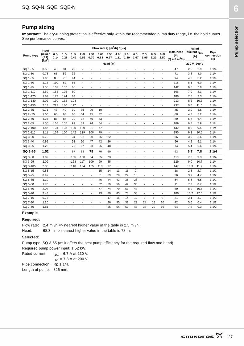
Pump sizingImportant: The dry-running protection is effective only within the recommended pump duty range, i.e. the bold curves. See performance curves.
Example
Required:
Flow rate: 2.4 m3/h => nearest higher value in the table is 2.5 m3/h.
Head: 68.3 m => nearest higher value in the table is 78 m.
Selected:
Pump type: SQ 3-65 (as it offers the best pump efficiency for the required flow and head).
Required pump power input: 1.52 kW.
Rated current: I1/1 = 6.7 A at 230 V.
I1/1 = 7.8 A at 200 V.
Pipe connection: Rp 1 1/4.
Length of pump: 826 mm.
Pump type
Input power (P1)[kW]
Flow rate Q [m3/h] / [l/s]Max. head
[m]
(Q = 0 m3/h)
Rated current I1/1
[A]Pipe
connectionRp
0.5/0.14
1.0/0.28
1.5/0.42
2.0/0.56
2.5/0.70
3.0/0.83
3.5/0.97
4.0/1.11
5.0/1.39
6.0/1.67
7.0/1.95
8.0/2.22
9.0/2.50
Head [m] 230 V 200 V
SQ 1-35 0.58 43 34 20 - - - - - - - - - - 47 2.5 2.9 1 1/4
SQ 1-50 0.78 65 52 32 - - - - - - - - - - 71 3.3 4.0 1 1/4
SQ 1-65 1.00 88 70 44 - - - - - - - - - - 94 4.3 5.2 1 1/4
SQ 1-80 1.18 110 89 56 - - - - - - - - - - 118 5.1 6.0 1 1/4
SQ 1-95 1.38 132 107 68 - - - - - - - - - - 142 6.0 7.0 1 1/4
SQ 1-110 1.59 155 125 80 - - - - - - - - - - 166 7.0 8.1 1 1/4
SQ 1-125 1.82 177 144 93 - - - - - - - - - - 189 7.8 9.3 1 1/4
SQ 1-140 2.02 199 162 104 - - - - - - - - - - 213 8.6 10.3 1 1/4
SQ 1-155 2.19 222 180 117 - - - - - - - - - - 237 9.6 11.0 1 1/4
SQ 2-35 0.71 43 42 39 35 29 19 - - - - - - - 45 3.0 3.6 1 1/4
SQ 2- 55 1.00 66 63 60 54 45 32 - - - - - - - 68 4.3 5.2 1 1/4
SQ 2-70 1.27 87 84 79 72 60 43 - - - - - - - 89 5.5 6.4 1 1/4
SQ 2-85 1.55 108 105 99 89 74 54 - - - - - - - 109 6.8 7.9 1 1/4
SQ 2-100 1.86 131 128 120 109 91 67 - - - - - - - 132 8.0 9.5 1 1/4
SQ 2-115 2.11 154 150 142 129 108 79 - - - - - - - 155 9.3 10.6 1 1/4
SQ 3-30 0.70 - - 34 32 30 26 22 - - - - - - 36 3.0 3.6 1 1/4
SQ 3-40 0.99 - - 53 50 47 42 36 - - - - - - 56 4.2 5.1 1 1/4
SQ 3-55 1.25 - - 70 67 63 56 48 - - - - - - 74 5.4 6.6 1 1/4
SQ 3-65 1.52 - - 87 83 78 70 60 - - - - - - 92 6.7 7.8 1 1/4
SQ 3-80 1.82 - - 105 100 94 85 73 - - - - - - 110 7.8 9.3 1 1/4
SQ 3-95 2.09 - - 123 117 109 99 85 - - - - - - 129 9.0 10.7 1 1/4
SQ 3-105 2.33 - - 140 134 125 113 97 - - - - - - 147 10.3 11.7 1 1/4
SQ 5-15 0.53 - - - - - 15 14 13 11 7 - - - 18 2.3 2.7 1 1/2
SQ 5-25 0.92 - - - - - 31 29 28 24 18 - - - 36 3.9 4.7 1 1/2
SQ 5-35 1.29 - - - - - 46 44 42 36 28 - - - 54 5.6 6.5 1 1/2
SQ 5-50 1.70 - - - - - 62 59 56 49 38 - - - 71 7.3 8.7 1 1/2
SQ 5-60 2.08 - - - - - 77 74 70 61 48 - - - 89 8.9 10.6 1 1/2
SQ 5-70 2.43 - - - - - 93 89 85 73 58 - - - 106 10.7 12.0 1 1/2
SQ 7-15 0.73 - - - - - - 17 16 14 12 9 6 2 21 3.1 3.7 1 1/2
SQ 7-30 1.26 - - - - - - 36 35 32 29 24 18 10 42 5.5 6.4 1 1/2
SQ 7-40 1.81 - - - - - - 56 54 50 45 38 29 19 64 7.8 9.3 1 1/2
27
Pu
mp
se
lec
tion
28
SQ, SQ-N, SQE, SQE-N6
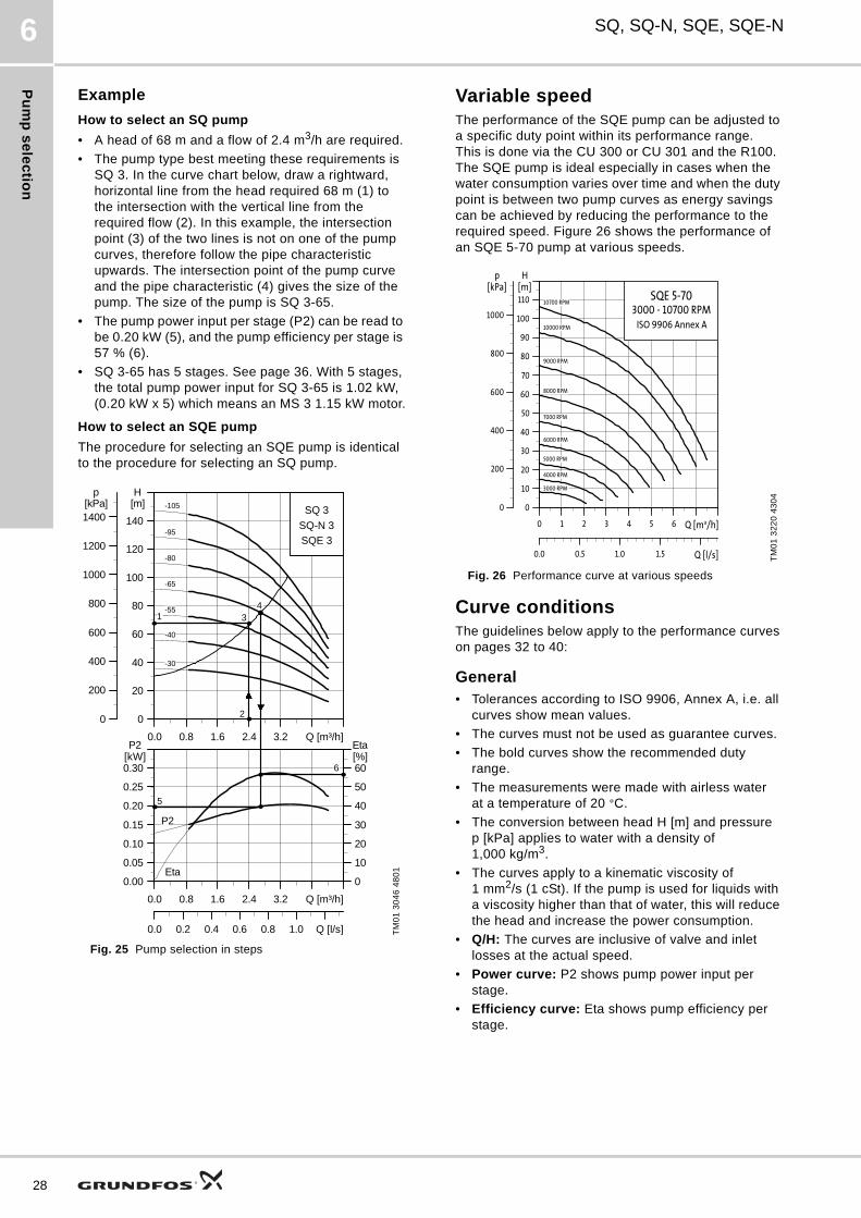
Example
How to select an SQ pump
• A head of 68 m and a flow of 2.4 m3/h are required.
• The pump type best meeting these requirements is SQ 3. In the curve chart below, draw a rightward, horizontal line from the head required 68 m (1) to the intersection with the vertical line from the required flow (2). In this example, the intersection point (3) of the two lines is not on one of the pump curves, therefore follow the pipe characteristic upwards. The intersection point of the pump curve and the pipe characteristic (4) gives the size of the pump. The size of the pump is SQ 3-65.
• The pump power input per stage (P2) can be read to be 0.20 kW (5), and the pump efficiency per stage is 57 % (6).
• SQ 3-65 has 5 stages. See page 36. With 5 stages, the total pump power input for SQ 3-65 is 1.02 kW, (0.20 kW x 5) which means an MS 3 1.15 kW motor.
How to select an SQE pump
The procedure for selecting an SQE pump is identical to the procedure for selecting an SQ pump.
Fig. 25 Pump selection in steps
Variable speedThe performance of the SQE pump can be adjusted to a specific duty point within its performance range. This is done via the CU 300 or CU 301 and the R100.The SQE pump is ideal especially in cases when the water consumption varies over time and when the duty point is between two pump curves as energy savings can be achieved by reducing the performance to the required speed. Figure 26 shows the performance of an SQE 5-70 pump at various speeds.
Fig. 26 Performance curve at various speeds
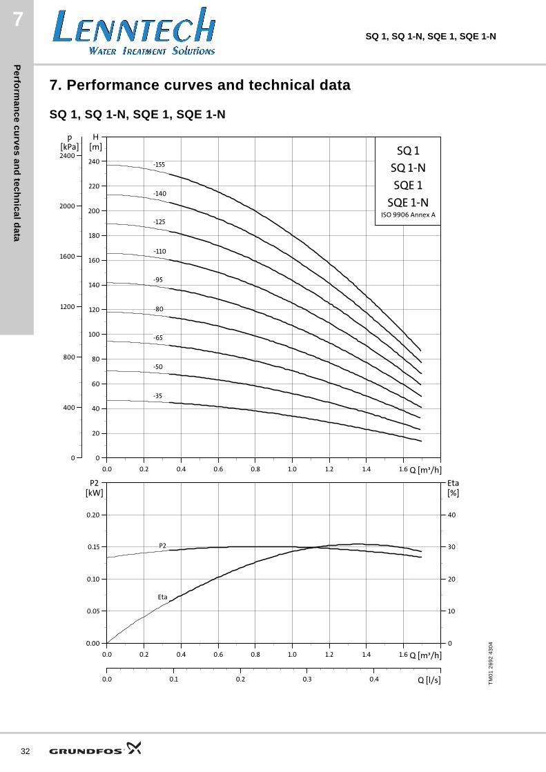
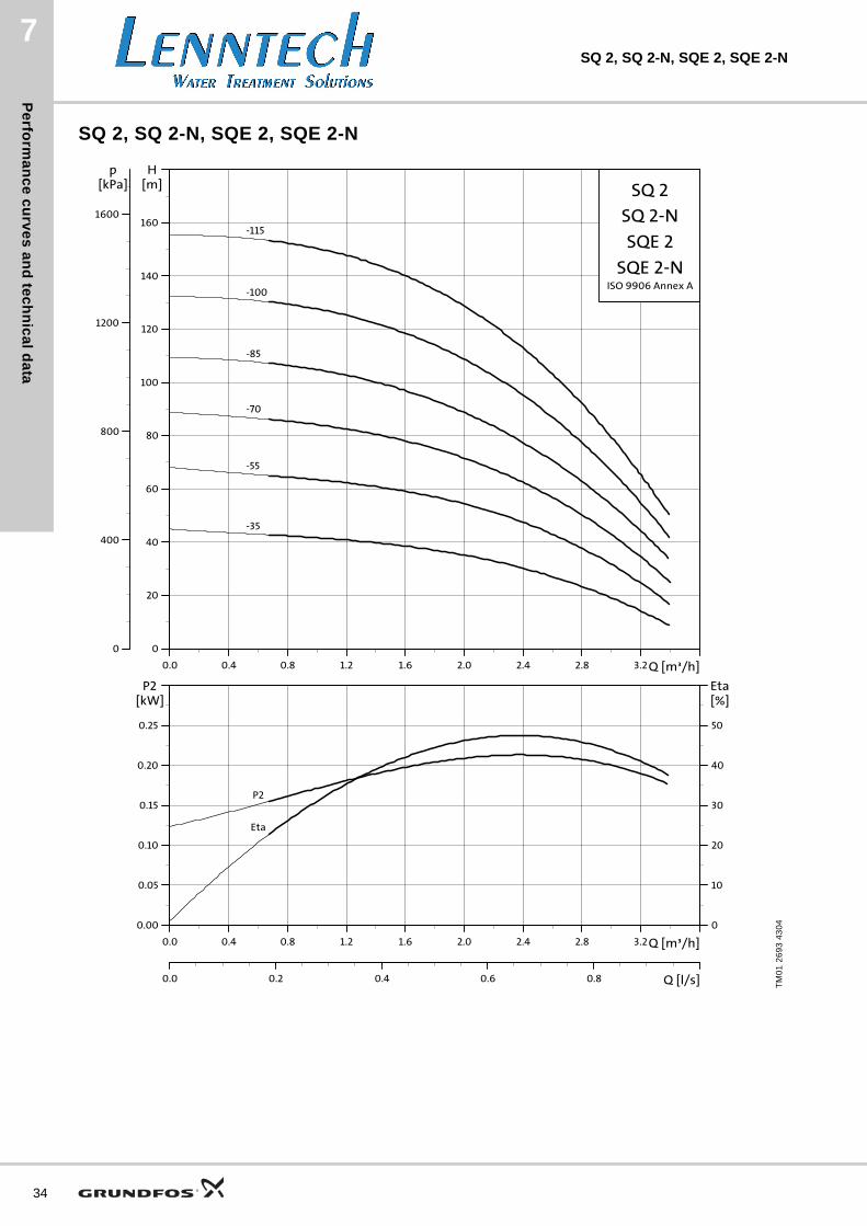
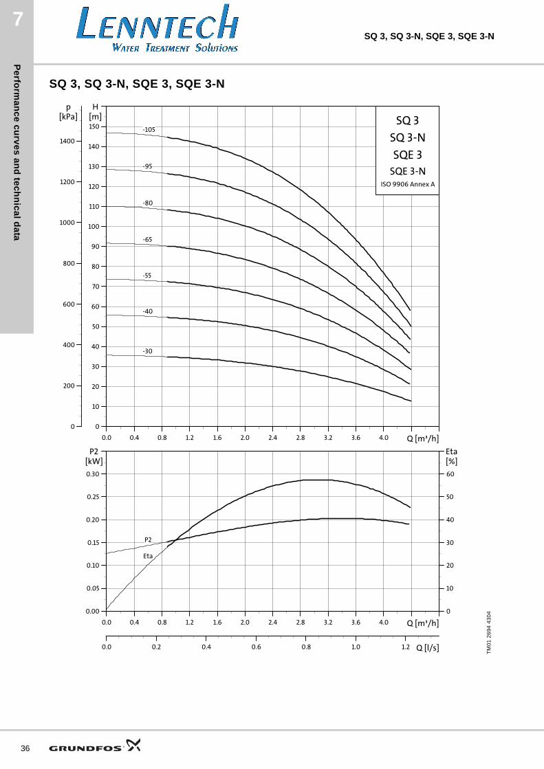
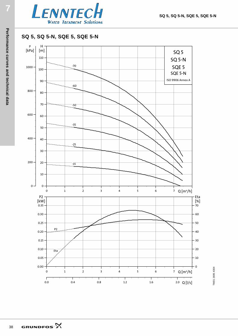
Curve conditionsThe guidelines below apply to the performance curves on pages 32 to 40:
General• Tolerances according to ISO 9906, Annex A, i.e. all
curves show mean values.
• The curves must not be used as guarantee curves.
• The bold curves show the recommended duty range.
• The measurements were made with airless water at a temperature of 20 °C.
• The conversion between head H [m] and pressure p [kPa] applies to water with a density of 1,000 kg/m3.
• The curves apply to a kinematic viscosity of 1 mm2/s (1 cSt). If the pump is used for liquids with a viscosity higher than that of water, this will reduce the head and increase the power consumption.
• Q/H: The curves are inclusive of valve and inlet losses at the actual speed.
• Power curve: P2 shows pump power input per stage.
• Efficiency curve: Eta shows pump efficiency per stage.
TM
01
30
46
48
01
0.0 0.8 1.6 2.4 3.2 Q [m³/h]
0
20
40
60
80
100
120
140
H[m]
0
200
400
600
800
1000
1200
1400[kPa]
p
SQ 3
SQE 3SQ-N 3
-105
-95
-80
-65
-55
-40
-30
1
2
34
0.0 0.8 1.6 2.4 3.2 Q [m³/h]
0.00
0.05
0.10
0.15
0.20
0.25
0.30
P2[kW]
0
10
20
30
40
50
60[%]Eta
0.0 0.2 0.4 0.6 0.8 1.0 Q [l/s]
P2
Eta
5
6T
M0
1 3
22
0 4
30
4
0 1 2 3 4 5 6 Q [m³/h]
0
10
20
30
40
50
60
70
80
90
100
110
H[m]
0.0 0.5 1.0 1.5 Q [l/s]
0
200
400
600
800
1000
p[kPa]
SQE 5-703000 - 10700 RPM
ISO 9906 Annex A
3000 RPM
4000 RPM
5000 RPM
6000 RPM
7000 RPM
8000 RPM
9000 RPM
10000 RPM
10700 RPM
Pu
mp
se
lec
tio
n
SQ, SQ-N, SQE, SQE-N 6
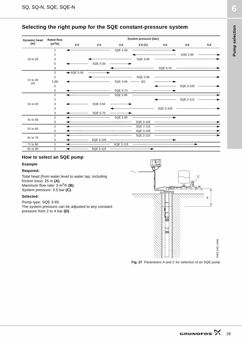
Selecting the right pump for the SQE constant-pressure system
How to select an SQE pump
Example
Required:
Total head (from water level to water tap, including friction loss): 25 m (A).Maximum flow rate: 3 m3/h (B).System pressure: 3.5 bar (C).
Selected:
Pump type: SQE 3-65.The system pressure can be adjusted to any constant pressure from 2 to 4 bar (D).
Fig. 27 Parameters A and C for selection of an SQE pump
Dynamic head[m]
Rated flow
[m3/h]
System pressure [bar]
2.0 2.5 3.0 3.5 (C) 4.0 4.5 5.0
10 to 20
2 SQE 2-55
2 SQE 2-85
3 SQE 3-65
5 SQE 5-50
5 SQE 5-70
21 to 30(A)
2 SQE 2-55
2 SQE 2-85
3 (B) SQE 3-65 (D)
5 SQE 3-105
5 SQE 5-70
31 to 40
2 SQE 2-85
2 SQE 2-115
3 SQE 3-65
3 SQE 3-105
3 SQE 5-70
41 to 502 SQE 2-85
3 SQE 3-105
51 to 602 SQE 2-115
3 SQE 3-105
61 to 702 SQE 2-115
3 SQE 3-105
71 to 80 2 SQE 2-115
81 to 90 2 SQE 2-115
TM
03
34
31
04
06
C
A
29
Pu
mp
se
lec
tion
30
SQ, SQ-N, SQE, SQE-N6
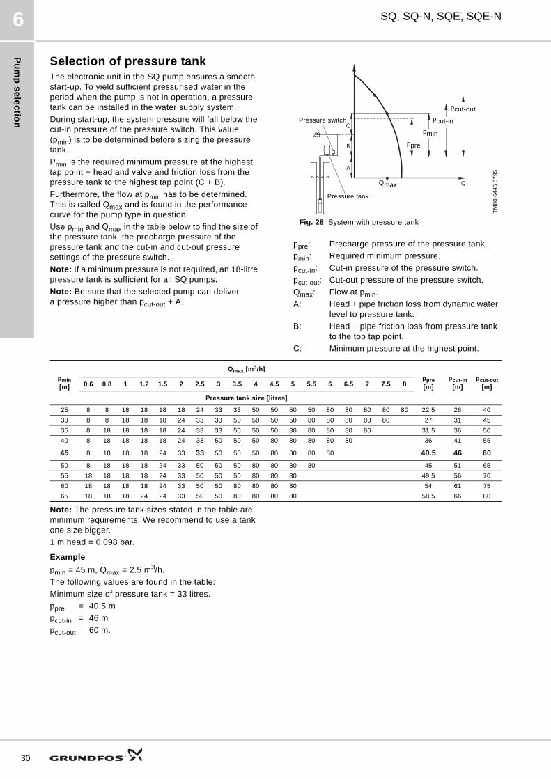
Selection of pressure tankThe electronic unit in the SQ pump ensures a smooth start-up. To yield sufficient pressurised water in the period when the pump is not in operation, a pressure tank can be installed in the water supply system.
During start-up, the system pressure will fall below the cut-in pressure of the pressure switch. This value (pmin) is to be determined before sizing the pressure tank.
Pmin is the required minimum pressure at the highest tap point + head and valve and friction loss from the pressure tank to the highest tap point (C + B).
Furthermore, the flow at pmin has to be determined. This is called Qmax and is found in the performance curve for the pump type in question.
Use pmin and Qmax in the table below to find the size of the pressure tank, the precharge pressure of the pressure tank and the cut-in and cut-out pressure settings of the pressure switch.
Note: If a minimum pressure is not required, an 18-litre pressure tank is sufficient for all SQ pumps.
Note: Be sure that the selected pump can deliver a pressure higher than pcut-out + A.
Fig. 28 System with pressure tank
Note: The pressure tank sizes stated in the table are minimum requirements. We recommend to use a tank one size bigger.
1 m head = 0.098 bar.
Example
pmin = 45 m, Qmax = 2.5 m3/h.
The following values are found in the table:
Minimum size of pressure tank = 33 litres.
ppre = 40.5 m
pcut-in = 46 m
pcut-out = 60 m.
TM
00
64
45
37
95
ppre: Precharge pressure of the pressure tank.
pmin: Required minimum pressure.
pcut-in: Cut-in pressure of the pressure switch.
pcut-out: Cut-out pressure of the pressure switch.
Qmax: Flow at pmin.
A: Head + pipe friction loss from dynamic water level to pressure tank.
B: Head + pipe friction loss from pressure tank to the top tap point.
C: Minimum pressure at the highest point.
C
B
A
Q
Pressure switch
pcut-out
pcut-in
pmin
ppre
Qmax
Pressure tank
pmin[m]
Qmax [m3/h]
ppre[m]
pcut-in[m]
pcut-out[m]0.6 0.8 1 1.2 1.5 2 2.5 3 3.5 4 4.5 5 5.5 6 6.5 7 7.5 8
Pressure tank size [litres]
25 8 8 18 18 18 18 24 33 33 50 50 50 50 80 80 80 80 80 22.5 26 40
30 8 8 18 18 18 24 33 33 50 50 50 50 80 80 80 80 80 27 31 45
35 8 18 18 18 18 24 33 33 50 50 50 80 80 80 80 80 31.5 36 50
40 8 18 18 18 18 24 33 50 50 50 80 80 80 80 80 36 41 55
45 8 18 18 18 24 33 33 50 50 50 80 80 80 80 40.5 46 60
50 8 18 18 18 24 33 50 50 50 80 80 80 80 45 51 65
55 18 18 18 18 24 33 50 50 50 80 80 80 49.5 56 70
60 18 18 18 18 24 33 50 50 80 80 80 80 54 61 75
65 18 18 18 24 24 33 50 50 80 80 80 80 58.5 66 80

31
Pe
rform
an
ce
cu
rve
s a
nd
tec
hn
ica
l da
ta
32
7SQ 1, SQ 1-N, SQE 1, SQE 1-N
7. Performance curves and technical data
SQ 1, SQ 1-N, SQE 1, SQE 1-N
TM
01
26
92
43
04
0.0 0.2 0.4 0.6 0.8 1.0 1.2 1.4 1.6 Q [m³/h]
0
20
40
60
80
100
120
140
160
180
200
220
240
H[m]
0
400
800
1200
1600
2000
2400
p[kPa] SQ 1
SQE 1
ISO 9906 Annex A
SQ 1-N
SQE 1-N
-155
-140
-125
-110
-95
-80
-65
-50
-35
0.0 0.2 0.4 0.6 0.8 1.0 1.2 1.4 1.6 Q [m³/h]
0.00
0.05
0.10
0.15
0.20
P2[kW]
0
10
20
30
40
[%]Eta
0.0 0.1 0.2 0.3 0.4 Q [l/s]
P2
Eta
Pe
rfo
rma
nc
e c
urv
es
an
d t
ec
hn
ica
l d
ata
7SQ 1, SQ 1-N, SQE 1, SQE 1-N
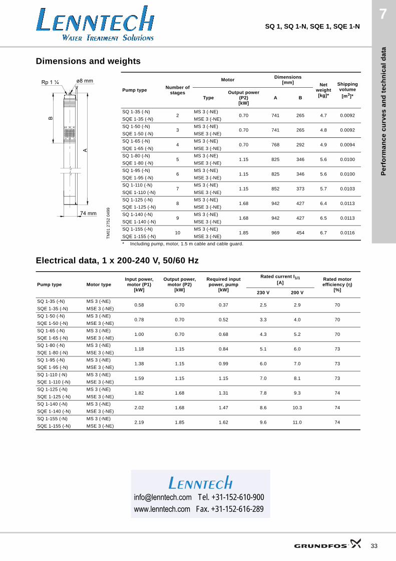
Dimensions and weights
Electrical data, 1 x 200-240 V, 50/60 Hz
TM
01
27
52
04
99
Pump typeNumber of
stages
MotorDimensions
[mm] Net weight[kg]*
Shipping volume
[m3]*TypeOutput power
(P2)[kW]
A B
SQ 1-35 (-N)2
MS 3 (-NE)0.70 741 265 4.7 0.0092
SQE 1-35 (-N) MSE 3 (-NE)
SQ 1-50 (-N)3
MS 3 (-NE)0.70 741 265 4.8 0.0092
SQE 1-50 (-N) MSE 3 (-NE)
SQ 1-65 (-N)4
MS 3 (-NE)0.70 768 292 4.9 0.0094
SQE 1-65 (-N) MSE 3 (-NE)
SQ 1-80 (-N)5
MS 3 (-NE)1.15 825 346 5.6 0.0100
SQE 1-80 (-N) MSE 3 (-NE)
SQ 1-95 (-N)6
MS 3 (-NE)1.15 825 346 5.6 0.0100
SQE 1-95 (-N) MSE 3 (-NE)
SQ 1-110 (-N)7
MS 3 (-NE)1.15 852 373 5.7 0.0103
SQE 1-110 (-N) MSE 3 (-NE)
SQ 1-125 (-N)8
MS 3 (-NE)1.68 942 427 6.4 0.0113
SQE 1-125 (-N) MSE 3 (-NE)
SQ 1-140 (-N)9
MS 3 (-NE)1.68 942 427 6.5 0.0113
SQE 1-140 (-N) MSE 3 (-NE)
SQ 1-155 (-N)10
MS 3 (-NE)1.85 969 454 6.7 0.0116
SQE 1-155 (-N) MSE 3 (-NE)
* Including pump, motor, 1.5 m cable and cable guard.
Pump type Motor typeInput power, motor (P1)
[kW]
Output power, motor (P2)
[kW]
Required input power, pump
[kW]
Rated current I1/1[A]
Rated motor efficiency (η)
[%]230 V 200 V
SQ 1-35 (-N) MS 3 (-NE)0.58 0.70 0.37 2.5 2.9 70
SQE 1-35 (-N) MSE 3 (-NE)
SQ 1-50 (-N) MS 3 (-NE)0.78 0.70 0.52 3.3 4.0 70
SQE 1-50 (-N) MSE 3 (-NE)
SQ 1-65 (-N) MS 3 (-NE)1.00 0.70 0.68 4.3 5.2 70
SQE 1-65 (-N) MSE 3 (-NE)
SQ 1-80 (-N) MS 3 (-NE)1.18 1.15 0.84 5.1 6.0 73
SQE 1-80 (-N) MSE 3 (-NE)
SQ 1-95 (-N) MS 3 (-NE)1.38 1.15 0.99 6.0 7.0 73
SQE 1-95 (-N) MSE 3 (-NE)
SQ 1-110 (-N) MS 3 (-NE)1.59 1.15 1.15 7.0 8.1 73
SQE 1-110 (-N) MSE 3 (-NE)
SQ 1-125 (-N) MS 3 (-NE)1.82 1.68 1.31 7.8 9.3 74
SQE 1-125 (-N) MSE 3 (-NE)
SQ 1-140 (-N) MS 3 (-NE)2.02 1.68 1.47 8.6 10.3 74
SQE 1-140 (-N) MSE 3 (-NE)
SQ 1-155 (-N) MS 3 (-NE)2.19 1.85 1.62 9.6 11.0 74
SQE 1-155 (-N) MSE 3 (-NE)
[email protected] Tel. +31-152-610-900www.lenntech.com Fax. [email protected] Tel. +31-152-610-900www.lenntech.com Fax. +31-152-616-289
Lenntech
33
Pe
rform
an
ce
cu
rve
s a
nd
tec
hn
ica
l da
ta
34
7SQ 2, SQ 2-N, SQE 2, SQE 2-N
SQ 2, SQ 2-N, SQE 2, SQE 2-N
TM
01
26
93
43
04
0.0 0.4 0.8 1.2 1.6 2.0 2.4 2.8 3.2Q [m³/h]
0
20
40
60
80
100
120
140
160
H[m]
0
400
800
1200
1600
[kPa]p
SQ 2
SQE 2
ISO 9906 Annex A
SQ 2-N
SQE 2-N
-115
-100
-85
-70
-55
-35
0.0 0.4 0.8 1.2 1.6 2.0 2.4 2.8 3.2Q [m³/h]
0.00
0.05
0.10
0.15
0.20
0.25
P2[kW]
0
10
20
30
40
50
[%]Eta
0.0 0.2 0.4 0.6 0.8 Q [l/s]
P2
Eta
Pe
rfo
rma
nc
e c
urv
es
an
d t
ec
hn
ica
l d
ata
7SQ 2, SQ 2-N, SQE 2, SQE 2-N
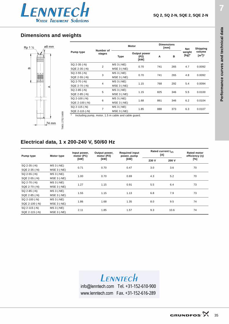
Dimensions and weights
Electrical data, 1 x 200-240 V, 50/60 Hz
TM
01
27
52
04
99
Pump typeNumber of
stages
MotorDimensions
[mm] Net weight[kg]*
Shipping volume
[m3]*TypeOutput power
(P2)[kW]
A B
SQ 2-35 (-N)2
MS 3 (-NE)0.70 741 265 4.7 0.0092
SQE 2-35 (-N) MSE 3 (-NE)
SQ 2-55 (-N)3
MS 3 (-NE)0.70 741 265 4.8 0.0092
SQE 2-55 (-N) MSE 3 (-NE)
SQ 2-70 (-N)4
MS 3 (-NE)1.15 768 292 5.4 0.0094
SQE 2-70 (-N) MSE 3 (-NE)
SQ 2-85 (-N)5
MS 3 (-NE)1.15 825 346 5.5 0.0100
SQE 2-85 (-N) MSE 3 (-NE)
SQ 2-100 (-N)6
MS 3 (-NE)1.68 861 346 6.2 0.0104
SQE 2-100 (-N) MSE 3 (-NE)
SQ 2-115 (-N)7
MS 3 (-NE)1.85 888 373 6.3 0.0107
SQE 2-115 (-N) MSE 3 (-NE)
* Including pump, motor, 1.5 m cable and cable guard.
Pump type Motor typeInput power, motor (P1)
[kW]
Output power, motor (P2)
[kW]
Required input power, pump
[kW]
Rated current I1/1[A]
Rated motor efficiency (η)
[%]230 V 200 V
SQ 2-35 (-N) MS 3 (-NE)0.71 0.70 0.47 3.0 3.6 70
SQE 2-35 (-N) MSE 3 (-NE)
SQ 2-55 (-N) MS 3 (-NE)1.00 0.70 0.69 4.3 5.2 70
SQE 2-55 (-N) MSE 3 (-NE)
SQ 2-70 (-N) MS 3 (-NE)1.27 1.15 0.91 5.5 6.4 73
SQE 2-70 (-N) MSE 3 (-NE)
SQ 2-85 (-N) MS 3 (-NE)1.55 1.15 1.13 6.8 7.9 73
SQE 2-85 (-N) MSE 3 (-NE)
SQ 2-100 (-N) MS 3 (-NE)1.86 1.68 1.35 8.0 9.5 74
SQE 2-100 (-N) MSE 3 (-NE)
SQ 2-115 (-N) MS 3 (-NE)2.11 1.85 1.57 9.3 10.6 74
SQE 2-115 (-N) MSE 3 (-NE)
[email protected] Tel. +31-152-610-900www.lenntech.com Fax. [email protected] Tel. +31-152-610-900www.lenntech.com Fax. +31-152-616-289
Lenntech
35
Pe
rform
an
ce
cu
rve
s a
nd
tec
hn
ica
l da
ta
36
7SQ 3, SQ 3-N, SQE 3, SQE 3-N
SQ 3, SQ 3-N, SQE 3, SQE 3-N
TM
01
26
94
43
04
0.0 0.4 0.8 1.2 1.6 2.0 2.4 2.8 3.2 3.6 4.0 Q [m³/h]
0
10
20
30
40
50
60
70
80
90
100
110
120
130
140
150
H[m]
0
200
400
600
800
1000
1200
1400
[kPa]p
SQ 3
SQE 3
ISO 9906 Annex A
SQ 3-N
SQE 3-N
-105
-95
-80
-65
-55
-40
-30
0.0 0.4 0.8 1.2 1.6 2.0 2.4 2.8 3.2 3.6 4.0 Q [m³/h]
0.00
0.05
0.10
0.15
0.20
0.25
0.30
P2[kW]
0
10
20
30
40
50
60
[%]Eta
0.0 0.2 0.4 0.6 0.8 1.0 1.2 Q [l/s]
P2
Eta
Pe
rfo
rma
nc
e c
urv
es
an
d t
ec
hn
ica
l d
ata
7SQ 3, SQ 3-N, SQE 3, SQE 3-N
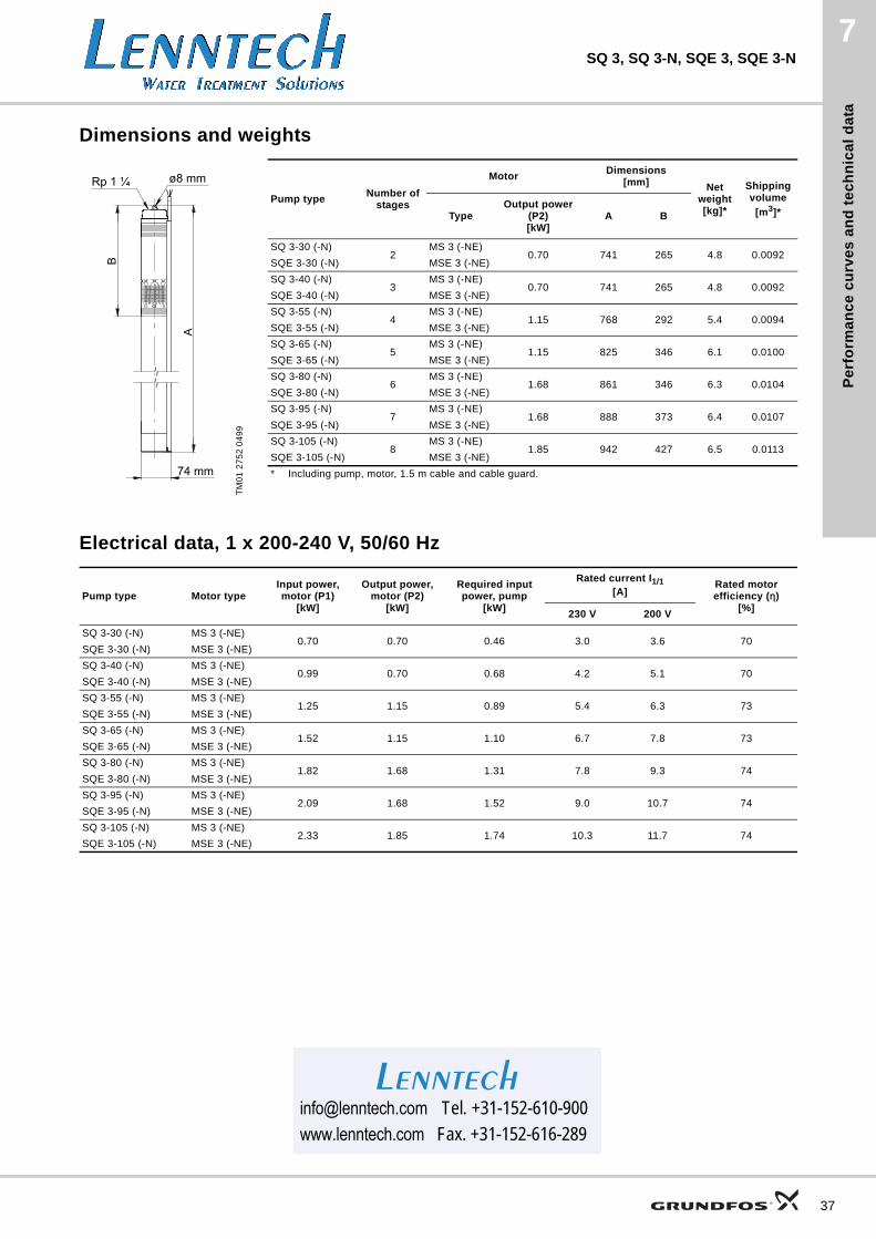
Dimensions and weights
Electrical data, 1 x 200-240 V, 50/60 Hz
TM
01
27
52
04
99
Pump typeNumber of
stages
MotorDimensions
[mm] Net weight[kg]*
Shipping volume
[m3]*TypeOutput power
(P2)[kW]
A B
SQ 3-30 (-N)2
MS 3 (-NE)0.70 741 265 4.8 0.0092
SQE 3-30 (-N) MSE 3 (-NE)
SQ 3-40 (-N)3
MS 3 (-NE)0.70 741 265 4.8 0.0092
SQE 3-40 (-N) MSE 3 (-NE)
SQ 3-55 (-N)4
MS 3 (-NE)1.15 768 292 5.4 0.0094
SQE 3-55 (-N) MSE 3 (-NE)
SQ 3-65 (-N)5
MS 3 (-NE)1.15 825 346 6.1 0.0100
SQE 3-65 (-N) MSE 3 (-NE)
SQ 3-80 (-N)6
MS 3 (-NE)1.68 861 346 6.3 0.0104
SQE 3-80 (-N) MSE 3 (-NE)
SQ 3-95 (-N)7
MS 3 (-NE)1.68 888 373 6.4 0.0107
SQE 3-95 (-N) MSE 3 (-NE)
SQ 3-105 (-N)8
MS 3 (-NE)1.85 942 427 6.5 0.0113
SQE 3-105 (-N) MSE 3 (-NE)
* Including pump, motor, 1.5 m cable and cable guard.
Pump type Motor typeInput power, motor (P1)
[kW]
Output power, motor (P2)
[kW]
Required input power, pump
[kW]
Rated current I1/1[A]
Rated motor efficiency (η)
[%]230 V 200 V
SQ 3-30 (-N) MS 3 (-NE)0.70 0.70 0.46 3.0 3.6 70
SQE 3-30 (-N) MSE 3 (-NE)
SQ 3-40 (-N) MS 3 (-NE)0.99 0.70 0.68 4.2 5.1 70
SQE 3-40 (-N) MSE 3 (-NE)
SQ 3-55 (-N) MS 3 (-NE)1.25 1.15 0.89 5.4 6.3 73
SQE 3-55 (-N) MSE 3 (-NE)
SQ 3-65 (-N) MS 3 (-NE)1.52 1.15 1.10 6.7 7.8 73
SQE 3-65 (-N) MSE 3 (-NE)
SQ 3-80 (-N) MS 3 (-NE)1.82 1.68 1.31 7.8 9.3 74
SQE 3-80 (-N) MSE 3 (-NE)
SQ 3-95 (-N) MS 3 (-NE)2.09 1.68 1.52 9.0 10.7 74
SQE 3-95 (-N) MSE 3 (-NE)
SQ 3-105 (-N) MS 3 (-NE)2.33 1.85 1.74 10.3 11.7 74
SQE 3-105 (-N) MSE 3 (-NE)
[email protected] Tel. +31-152-610-900www.lenntech.com Fax. [email protected] Tel. +31-152-610-900www.lenntech.com Fax. +31-152-616-289
Lenntech
37
Pe
rform
an
ce
cu
rve
s a
nd
tec
hn
ica
l da
ta
38
7SQ 5, SQ 5-N, SQE 5, SQE 5-N
SQ 5, SQ 5-N, SQE 5, SQE 5-N
TM
01
26
95
43
04
0 1 2 3 4 5 6 7 Q [m³/h]
0
10
20
30
40
50
60
70
80
90
100
110
H[m]
0
200
400
600
800
1000
[kPa]p
SQ 5
SQE 5
ISO 9906 Annex A
SQ 5-N
SQE 5-N
-70
-60
-50
-35
-25
-15
0 1 2 3 4 5 6 7 Q [m³/h]
0.00
0.05
0.10
0.15
0.20
0.25
0.30
0.35
P2[kW]
0
10
20
30
40
50
60
70[%]Eta
0.0 0.4 0.8 1.2 1.6 2.0 Q [l/s]
P2
Eta
Pe
rfo
rma
nc
e c
urv
es
an
d t
ec
hn
ica
l d
ata
7SQ 5, SQ 5-N, SQE 5, SQE 5-N
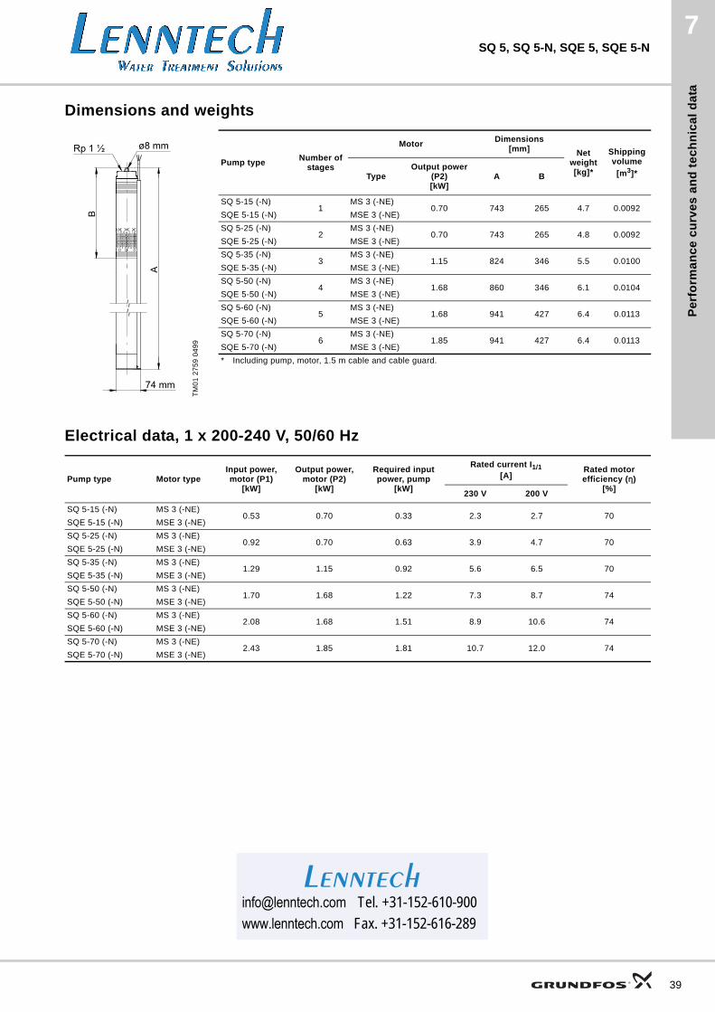
Dimensions and weights
Electrical data, 1 x 200-240 V, 50/60 Hz
TM
01
27
59
04
99
Pump typeNumber of
stages
MotorDimensions
[mm] Net weight[kg]*
Shipping volume
[m3]*TypeOutput power
(P2)[kW]
A B
SQ 5-15 (-N)1
MS 3 (-NE)0.70 743 265 4.7 0.0092
SQE 5-15 (-N) MSE 3 (-NE)
SQ 5-25 (-N)2
MS 3 (-NE)0.70 743 265 4.8 0.0092
SQE 5-25 (-N) MSE 3 (-NE)
SQ 5-35 (-N)3
MS 3 (-NE)1.15 824 346 5.5 0.0100
SQE 5-35 (-N) MSE 3 (-NE)
SQ 5-50 (-N)4
MS 3 (-NE)1.68 860 346 6.1 0.0104
SQE 5-50 (-N) MSE 3 (-NE)
SQ 5-60 (-N)5
MS 3 (-NE)1.68 941 427 6.4 0.0113
SQE 5-60 (-N) MSE 3 (-NE)
SQ 5-70 (-N)6
MS 3 (-NE)1.85 941 427 6.4 0.0113
SQE 5-70 (-N) MSE 3 (-NE)
* Including pump, motor, 1.5 m cable and cable guard.
Pump type Motor typeInput power, motor (P1)
[kW]
Output power, motor (P2)
[kW]
Required input power, pump
[kW]
Rated current I1/1[A]
Rated motor efficiency (η)
[%]230 V 200 V
SQ 5-15 (-N) MS 3 (-NE)0.53 0.70 0.33 2.3 2.7 70
SQE 5-15 (-N) MSE 3 (-NE)
SQ 5-25 (-N) MS 3 (-NE)0.92 0.70 0.63 3.9 4.7 70
SQE 5-25 (-N) MSE 3 (-NE)
SQ 5-35 (-N) MS 3 (-NE)1.29 1.15 0.92 5.6 6.5 70
SQE 5-35 (-N) MSE 3 (-NE)
SQ 5-50 (-N) MS 3 (-NE)1.70 1.68 1.22 7.3 8.7 74
SQE 5-50 (-N) MSE 3 (-NE)
SQ 5-60 (-N) MS 3 (-NE)2.08 1.68 1.51 8.9 10.6 74
SQE 5-60 (-N) MSE 3 (-NE)
SQ 5-70 (-N) MS 3 (-NE)2.43 1.85 1.81 10.7 12.0 74
SQE 5-70 (-N) MSE 3 (-NE)
[email protected] Tel. +31-152-610-900www.lenntech.com Fax. [email protected] Tel. +31-152-610-900www.lenntech.com Fax. +31-152-616-289
Lenntech
39
Pe
rform
an
ce
cu
rve
s a
nd
tec
hn
ica
l da
ta
40
7SQ 7, SQ 7-N, SQE 7, SQE 7-N
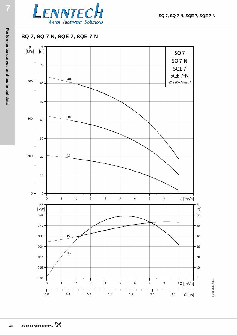
SQ 7, SQ 7-N, SQE 7, SQE 7-N
TM
01
26
96
43
04
0 1 2 3 4 5 6 7 8 Q [m³/h]
0
10
20
30
40
50
60
70
H[m]
0
200
400
600
[kPa]p
SQ 7
SQE 7
ISO 9906 Annex A
SQ 7-N
SQE 7-N-40
-30
-15
0 1 2 3 4 5 6 7 8 9Q [m³/h]
0.00
0.08
0.16
0.24
0.32
0.40
0.48
P2[kW]
0
10
20
30
40
50
60
[%]Eta
0.0 0.4 0.8 1.2 1.6 2.0 2.4 Q [l/s]
P2
Eta
Pe
rfo
rma
nc
e c
urv
es
an
d t
ec
hn
ica
l d
ata
7SQ 7, SQ 7-N, SQE 7, SQE 7-N
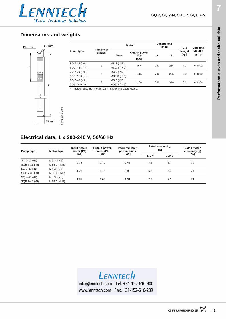
Dimensions and weights
Electrical data, 1 x 200-240 V, 50/60 Hz
TM
01
27
59
04
99
Pump typeNumber of
stages
MotorDimensions
[mm] Net weight[kg]*
Shipping volume
[m3]*TypeOutput power
(P2)[kW]
A B
SQ 7-15 (-N)1
MS 3 (-NE)0.7 743 265 4.7 0.0092
SQE 7-15 (-N) MSE 3 (-NE)
SQ 7-30 (-N)2
MS 3 (-NE)1.15 743 265 5.2 0.0092
SQE 7-30 (-N) MSE 3 (-NE)
SQ 7-40 (-N)3
MS 3 (-NE)1.68 860 346 6.1 0.0104
SQE 7-40 (-N) MSE 3 (-NE)
* Including pump, motor, 1.5 m cable and cable guard.
Pump type Motor typeInput power, motor (P1)
[kW]
Output power, motor (P2)
[kW]
Required input power, pump
[kW]
Rated current I1/1[A]
Rated motor efficiency (η)
[%]230 V 200 V
SQ 7-15 (-N) MS 3 (-NE)0.73 0.70 0.48 3.1 3.7 70
SQE 7-15 (-N) MSE 3 (-NE)
SQ 7-30 (-N) MS 3 (-NE)1.26 1.15 0.90 5.5 6.4 73
SQE 7-30 (-N) MSE 3 (-NE)
SQ 7-40 (-N) MS 3 (-NE)1.81 1.68 1.31 7.8 9.3 74
SQE 7-40 (-N) MSE 3 (-NE)
[email protected] Tel. +31-152-610-900www.lenntech.com Fax. [email protected] Tel. +31-152-610-900www.lenntech.com Fax. +31-152-616-289
Lenntech
41
Te
ch
nic
al d
ata
42
SQ, SQ-N, SQE, SQE-N8
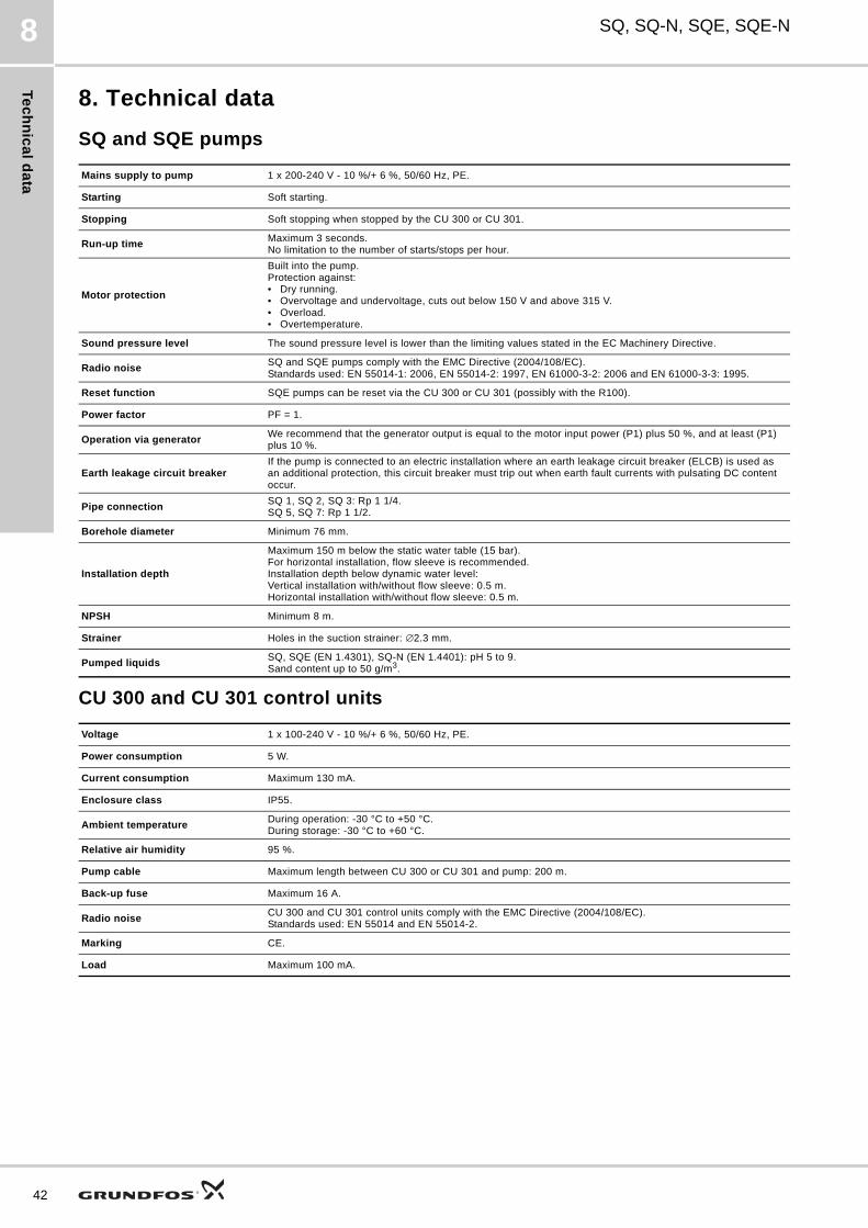
8. Technical data
SQ and SQE pumps
CU 300 and CU 301 control units
Mains supply to pump 1 x 200-240 V - 10 %/+ 6 %, 50/60 Hz, PE.
Starting Soft starting.
Stopping Soft stopping when stopped by the CU 300 or CU 301.
Run-up timeMaximum 3 seconds.No limitation to the number of starts/stops per hour.
Motor protection
Built into the pump.Protection against:• Dry running. • Overvoltage and undervoltage, cuts out below 150 V and above 315 V. • Overload.• Overtemperature.
Sound pressure level The sound pressure level is lower than the limiting values stated in the EC Machinery Directive.
Radio noiseSQ and SQE pumps comply with the EMC Directive (2004/108/EC).Standards used: EN 55014-1: 2006, EN 55014-2: 1997, EN 61000-3-2: 2006 and EN 61000-3-3: 1995.
Reset function SQE pumps can be reset via the CU 300 or CU 301 (possibly with the R100).
Power factor PF = 1.
Operation via generatorWe recommend that the generator output is equal to the motor input power (P1) plus 50 %, and at least (P1) plus 10 %.
Earth leakage circuit breakerIf the pump is connected to an electric installation where an earth leakage circuit breaker (ELCB) is used as an additional protection, this circuit breaker must trip out when earth fault currents with pulsating DC content occur.
Pipe connectionSQ 1, SQ 2, SQ 3: Rp 1 1/4.SQ 5, SQ 7: Rp 1 1/2.
Borehole diameter Minimum 76 mm.
Installation depth
Maximum 150 m below the static water table (15 bar).For horizontal installation, flow sleeve is recommended.Installation depth below dynamic water level:Vertical installation with/without flow sleeve: 0.5 m.Horizontal installation with/without flow sleeve: 0.5 m.
NPSH Minimum 8 m.
Strainer Holes in the suction strainer: ∅2.3 mm.
Pumped liquidsSQ, SQE (EN 1.4301), SQ-N (EN 1.4401): pH 5 to 9.Sand content up to 50 g/m3.
Voltage 1 x 100-240 V - 10 %/+ 6 %, 50/60 Hz, PE.
Power consumption 5 W.
Current consumption Maximum 130 mA.
Enclosure class IP55.
Ambient temperatureDuring operation: -30 °C to +50 °C.During storage: -30 °C to +60 °C.
Relative air humidity 95 %.
Pump cable Maximum length between CU 300 or CU 301 and pump: 200 m.
Back-up fuse Maximum 16 A.
Radio noiseCU 300 and CU 301 control units comply with the EMC Directive (2004/108/EC).Standards used: EN 55014 and EN 55014-2.
Marking CE.
Load Maximum 100 mA.
Te
ch
nic
al
da
ta
SQ, SQ-N, SQE, SQE-N 8
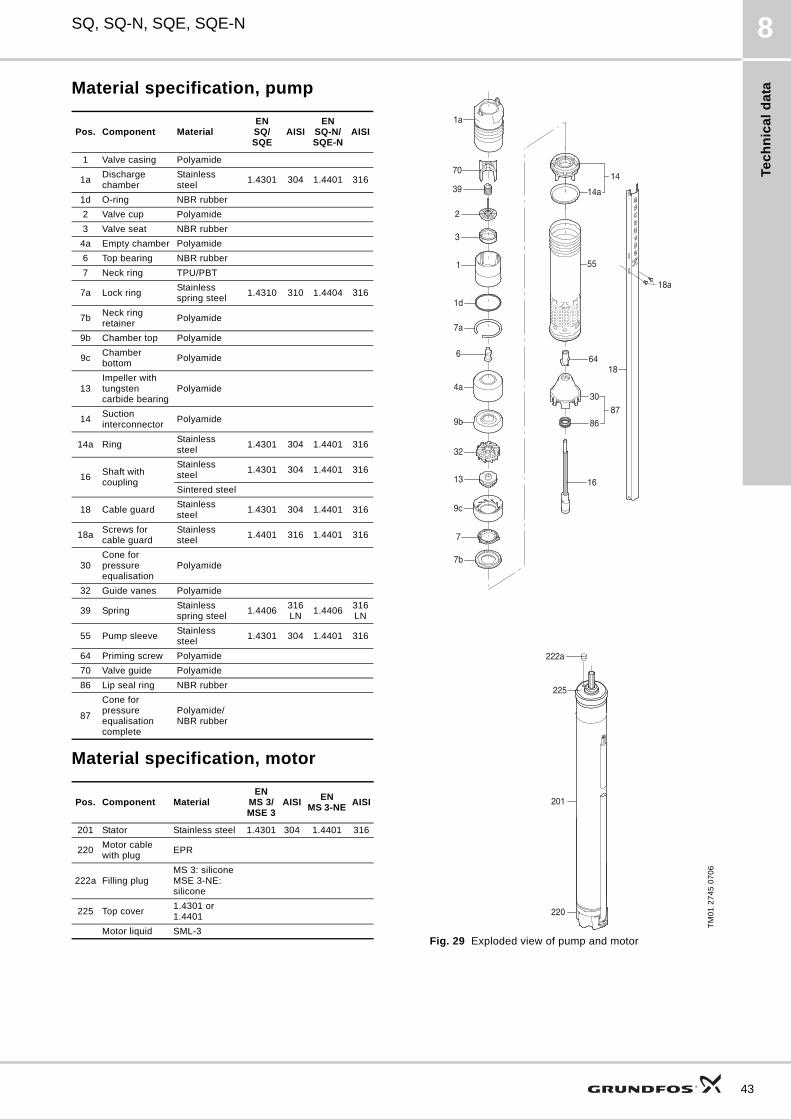
Material specification, pump
Material specification, motor
Fig. 29 Exploded view of pump and motor
Pos. Component MaterialENSQ/SQE
AISIEN
SQ-N/SQE-N
AISI
1 Valve casing Polyamide
1aDischarge chamber
Stainless steel
1.4301 304 1.4401 316
1d O-ring NBR rubber
2 Valve cup Polyamide
3 Valve seat NBR rubber
4a Empty chamber Polyamide
6 Top bearing NBR rubber
7 Neck ring TPU/PBT
7a Lock ringStainless spring steel
1.4310 310 1.4404 316
7bNeck ring retainer
Polyamide
9b Chamber top Polyamide
9cChamber bottom
Polyamide
13Impeller with tungsten carbide bearing
Polyamide
14Suction interconnector
Polyamide
14a RingStainless steel
1.4301 304 1.4401 316
16Shaft with coupling
Stainless steel
1.4301 304 1.4401 316
Sintered steel
18 Cable guardStainless steel
1.4301 304 1.4401 316
18aScrews for cable guard
Stainless steel
1.4401 316 1.4401 316
30Cone for pressure equalisation
Polyamide
32 Guide vanes Polyamide
39 SpringStainless spring steel
1.4406316LN
1.4406316LN
55 Pump sleeveStainless steel
1.4301 304 1.4401 316
64 Priming screw Polyamide
70 Valve guide Polyamide
86 Lip seal ring NBR rubber
87
Cone for pressure equalisation complete
Polyamide/NBR rubber
Pos. Component MaterialEN
MS 3/MSE 3
AISIEN
MS 3-NEAISI
201 Stator Stainless steel 1.4301 304 1.4401 316
220Motor cable with plug
EPR
222a Filling plugMS 3: siliconeMSE 3-NE: silicone
225 Top cover1.4301 or 1.4401
Motor liquid SML-3
TM
01
27
45
07
06
1d
7a
1
70
2
39
3
1a
55
16
30
8687
6418
18a
6
4a
9b
32
13
9c
7
14
14a
7b
222a
225
201
220
43
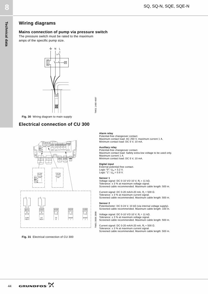
Te
ch
nic
al d
ata
44
SQ, SQ-N, SQE, SQE-N8
Wiring diagrams
Mains connection of pump via pressure switchThe pressure switch must be rated to the maximum amps of the specific pump size.
Fig. 30 Wiring diagram to main supply
Electrical connection of CU 300
Fig. 31 Electrical connection of CU 300
TM
01
14
80
46
97
N L
P
TM
01
30
08
28
98
Alarm relayPotential-free changeover contact.Maximum contact load: AC 250 V, maximum current 1 A.Minimum contact load: DC 5 V, 10 mA.
Auxiliary relayPotential-free changeover contact.Maximum contact load: Safety extra-low voltage to be used only. Maximum current 1 A.Minimum contact load: DC 5 V, 10 mA.
Digital inputExternal potential-free contact.Logic "0": Uin > 3.2 V.Logic "1": Uin < 0.9 V.
Sensor 1Voltage signal: DC 0-10 V/2-10 V, Ri = 11 kΩ.Tolerance: ± 3 % at maximum voltage signal. Screened cable recommended. Maximum cable length: 500 m.
Current signal: DC 0-20 mA/4-20 mA, Ri = 500 Ω.Tolerance: ± 3 % at maximum current signal. Screened cable recommended. Maximum cable length: 500 m.
Sensor 2Potentiometer: DC 0-24 V, 10 kΩ (via internal voltage supply).Screened cable recommended. Maximum cable length: 100 m.
Voltage signal: DC 0-10 V/2-10 V, Ri = 11 kΩ.Tolerance: ± 3 % at maximum voltage signal. Screened cable recommended. Maximum cable length: 500 m.
Current signal: DC 0-20 mA/4-20 mA, Ri = 500 Ω.Tolerance: ± 3 % at maximum current signal. Screened cable recommended. Maximum cable length: 500 m.
POWERPE
PUMP
RELAYALARM
CO
MN
C
NO
NO
NC
CO
M
AUXRELAY IN
DIG
IN+24V
DC
GN
D
GN
D
+24V
DC
IN
SENSOR1 2
SENSOR
IN+24V
DC
GN
D
RS485
RS232
B Y A RI
DTR
RX
DG
ND
5 6 7
1 2
1098
3 4
111213 161514 171819
PE
TXD
PE
21
PEPOWER PUMP
3 4
765
NO
NC
CO
M
ALARMRELAY
8 9 10
RELAYAUX
CO
MN
C
NO
131211
GN
D
+2
4V
DC
IN
DIGIN
14 15 16
1SENSOR
IN+2
4V
DC
GN
D
191817
GN
D
+2
4V
DC
IN
SENSOR2
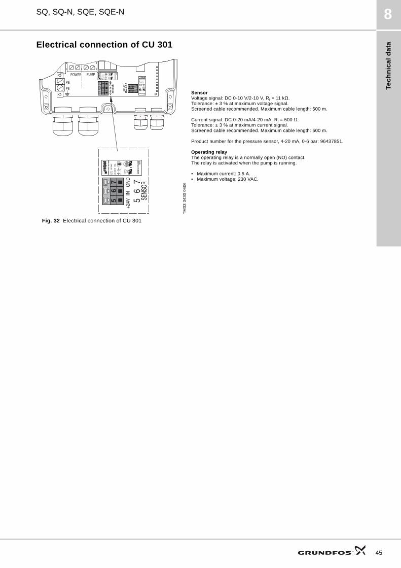
Te
ch
nic
al
da
ta
SQ, SQ-N, SQE, SQE-N 8
Electrical connection of CU 301
Fig. 32 Electrical connection of CU 301
TM
03
34
30
04
06
SensorVoltage signal: DC 0-10 V/2-10 V, Ri = 11 kΩ.Tolerance: ± 3 % at maximum voltage signal.Screened cable recommended. Maximum cable length: 500 m.
Current signal: DC 0-20 mA/4-20 mA, Ri = 500 Ω.Tolerance: ± 3 % at maximum current signal. Screened cable recommended. Maximum cable length: 500 m.
Product number for the pressure sensor, 4-20 mA, 0-6 bar: 96437851.
Operating relayThe operating relay is a normally open (NO) contact. The relay is activated when the pump is running.
• Maximum current: 0.5 A.• Maximum voltage: 230 VAC.
PE
PE
POWER PUMP
SENS
OR5
67
+24V
ING
ND
8
57
4
12relpol
RM
85-3
021-
25-1
024
MA
DE
IN P
OLA
ND
4080
AC
250
V
16 A
DC
24
V
56
78
5
7
4
12relpol
RM
85-3
021-
25-1
024
MA
DE
IN P
OLA
ND
4080
AC
250
V
16 A
DC
24
V
56
7
+24V
IN G
ND
8 57 4
1 2
relpolRM85-3021-25-1024
MADE IN POLAND4080
AC 250 V 16 A
DC 24 V
98R
ELAY
Max
. 0.5
A
SEN
SOR
45
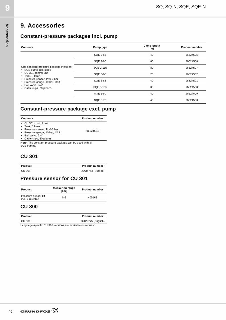
Ac
ce
ss
orie
s
46
SQ, SQ-N, SQE, SQE-N9
9. Accessories
Constant-pressure packages incl. pump
Constant-pressure package excl. pump
CU 301
Pressure sensor for CU 301
CU 300
Contents Pump typeCable length
[m]Product number
One constant-pressure package includes:• SQE pump incl. cable • CU 301 control unit• Tank, 8 litres• Pressure sensor, Pt 0-6 bar• Pressure gauge, 10 bar, ∅63• Ball valve, 3/4"• Cable clips, 20 pieces
SQE 2-55 40 96524505
SQE 2-85 60 96524506
SQE 2-115 80 96524507
SQE 3-65 20 96524502
SQE 3-65 40 96524501
SQE 3-105 80 96524508
SQE 5-50 40 96524509
SQE 5-70 40 96524503
Contents Product number
• CU 301 control unit• Tank, 8 litres• Pressure sensor, Pt 0-6 bar• Pressure gauge, 10 bar, ∅63• Ball valve, 3/4"• Cable clips, 20 pieces
96524504
Note: The constant-pressure package can be used with all SQE pumps.
Product Product number
CU 301 96436753 (Europe)
ProductMeasuring range
[bar]Product number
Pressure sensor kit incl. 2 m cable
0-6 405168
Product Product number
CU 300 96422775 (English)
Language-specific CU 300 versions are available on request.
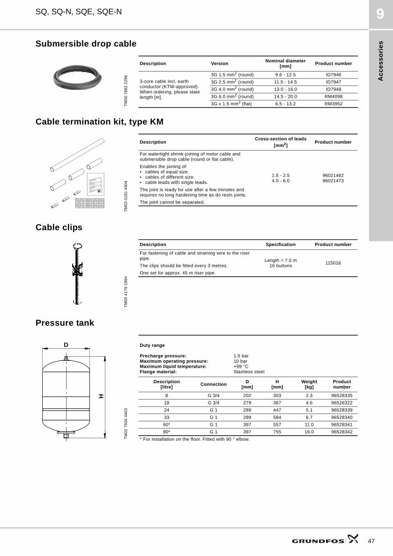
Ac
ce
ss
ori
es
SQ, SQ-N, SQE, SQE-N 9
Submersible drop cable
Cable termination kit, type KM
Cable clips
Pressure tank
TM
00
78
82
22
96
Description VersionNominal diameter
[mm]Product number
3-core cable incl. earth conductor (KTW-approved). When ordering, please state length [m].
3G 1.5 mm2 (round) 9.6 - 12.5 ID7946
3G 2.5 mm2 (round) 11.5 - 14.5 ID7947
3G 4.0 mm2 (round) 13.0 - 16.0 ID7948
3G 6.0 mm2 (round) 14.5 - 20.0 RM4098
3G x 1.5 mm2 (flat) 6.5 - 13.2 RM3952
TM
03
01
81
44
04
DescriptionCross-section of leads
[mm2]Product number
For watertight shrink-joining of motor cable and submersible drop cable (round or flat cable).
1.5 - 2.5 4.0 - 6.0
9602146296021473
Enables the joining of:• cables of equal size.• cables of different size.• cable leads with single leads.
The joint is ready for use after a few minutes and requires no long hardening time as do resin joints.
The joint cannot be separated.
Renseserviet imprægneret
med 1,1,1 trichlorethan
(farlig ved indånding eller
indtagelse)
Reinigungstuch getrankt
mit 1,1,1 Trichlorethan
(gesundheltsschadelich beim Einatmen
oder Verschlucken)
Cleaning tissue impregnated
with 1,1,1 trichloroethane
(health hazard when inhaled or
swallowed)
EPPA 207-3
TM
00
41
79
19
94
Description Specification Product number
For fastening of cable and straining wire to the riser pipe. Length = 7.5 m
16 buttons115016
The clips should be fitted every 3 metres.
One set for approx. 45 m riser pipe.
TM
02
79
34
44
03
Duty range
Precharge pressure:Maximum operating pressure:Maximum liquid temperature:Flange material:
1.5 bar10 bar+99 °CStainless steel
Description[litre]
ConnectionD
[mm]H
[mm]Weight
[kg]Product number
8 G 3/4 202 303 2.3 96528335
18 G 3/4 279 367 4.6 96526322
24 G 1 289 447 5.1 96528339
33 G 1 289 584 6.7 96528340
60* G 1 397 557 11.0 96528341
80* G 1 397 755 16.0 96528342
* For installation on the floor. Fitted with 90 ° elbow.
D
H
47
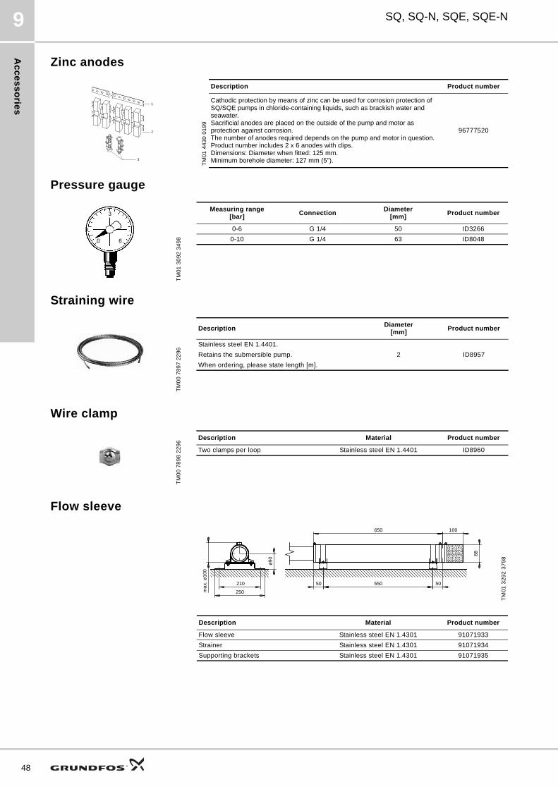
Ac
ce
ss
orie
s
48
SQ, SQ-N, SQE, SQE-N9
Zinc anodes
Pressure gauge
Straining wire
Wire clamp
Flow sleeve
TM
01
44
30
01
99
Description Product number
Cathodic protection by means of zinc can be used for corrosion protection of SQ/SQE pumps in chloride-containing liquids, such as brackish water and seawater. Sacrificial anodes are placed on the outside of the pump and motor as protection against corrosion.The number of anodes required depends on the pump and motor in question.Product number includes 2 x 6 anodes with clips.Dimensions: Diameter when fitted: 125 mm.Minimum borehole diameter: 127 mm (5").
96777520
1
2
3
TM
01
30
92
34
98
Measuring range[bar]
Connection Diameter
[mm]Product number
0-6 G 1/4 50 ID3266
0-10 G 1/4 63 ID8048
TM
00
78
97
22
96
DescriptionDiameter
[mm]Product number
Stainless steel EN 1.4401.
2 ID8957Retains the submersible pump.
When ordering, please state length [m].
TM
00
78
98
22
96
Description Material Product number
Two clamps per loop Stainless steel EN 1.4401 ID8960
TM
01
32
92
37
98
55050
88
650 100
50210
250max
. ø10
0
ø90
Description Material Product number
Flow sleeve Stainless steel EN 1.4301 91071933
Strainer Stainless steel EN 1.4301 91071934
Supporting brackets Stainless steel EN 1.4301 91071935
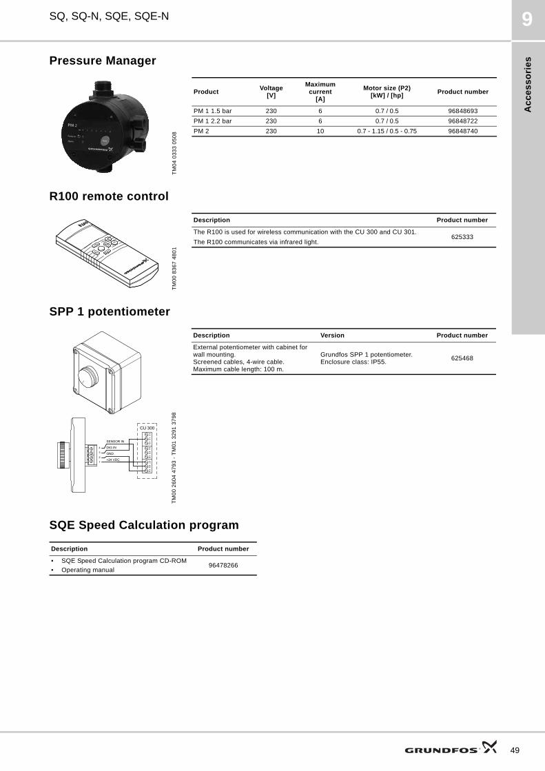
Ac
ce
ss
ori
es
SQ, SQ-N, SQE, SQE-N 9
Pressure Manager
R100 remote control
SPP 1 potentiometer
SQE Speed Calculation program
TM
04
03
33
05
08
ProductVoltage
[V]
Maximum current
[A]
Motor size (P2)[kW] / [hp]
Product number
PM 1 1.5 bar 230 6 0.7 / 0.5 96848693
PM 1 2.2 bar 230 6 0.7 / 0.5 96848722
PM 2 230 10 0.7 - 1.15 / 0.5 - 0.75 96848740
TM
00
83
67
48
01
Description Product number
The R100 is used for wireless communication with the CU 300 and CU 301.625333
The R100 communicates via infrared light.
TM
00
26
04
47
93
- T
M0
1 3
29
1 3
79
8
Description Version Product number
External potentiometer with cabinet for wall mounting.Screened cables, 4-wire cable.Maximum cable length: 100 m.
Grundfos SPP 1 potentiometer.Enclosure class: IP55.
625468
Description Product number
• SQE Speed Calculation program CD-ROM
• Operating manual96478266
49
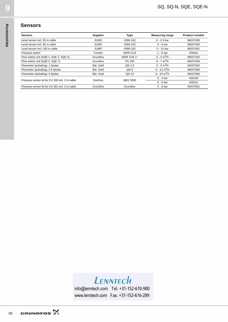
Ac
ce
ss
orie
s
50
SQ, SQ-N, SQE, SQE-N9
Sensors
Sensors Supplier Type Measuring range Product number
Level sensor incl. 30 m cable JUMO 4390-242 0 - 2.5 bar 96037489
Level sensor incl. 65 m cable JUMO 4390-242 0 - 6 bar 96037490
Level sensor incl. 105 m cable JUMO 4390-242 0 - 10 bar 96037491
Pressure switch Condor MDR 21/6 1 - 6 bar ID6462
Flow switch unit (SQE 1, SQE 2, SQE 3) Grundfos MDR 21/6 1" 0 - 5 m3/h 96037332
Flow switch unit (SQE 5, SQE 7) Grundfos FS 200 5 - 7 m3/h 96037559
Flowmeter (pulsating), 1 l/pulse Bdr. Dahl QN 2.5 0 - 5 m3/h 96037492
Flowmeter (pulsating), 2.5 l/pulse Bdr. Dahl QN 6 0 - 12 m3/h 96037583
Flowmeter (pulsating), 5 l/pulse Bdr. Dahl QN 10 0 - 20 m3/h 96037584
Pressure sensor kit for CU 300 incl. 2 m cable Danfoss MBS 30000 - 4 bar 405160
0 - 6 bar 405161
Pressure sensor kit for CU 301 incl. 2 m cable Grundfos Grundfos 0 - 6 bar 96437851
[email protected] Tel. +31-152-610-900www.lenntech.com Fax. [email protected] Tel. +31-152-610-900www.lenntech.com Fax. +31-152-616-289
Lenntech
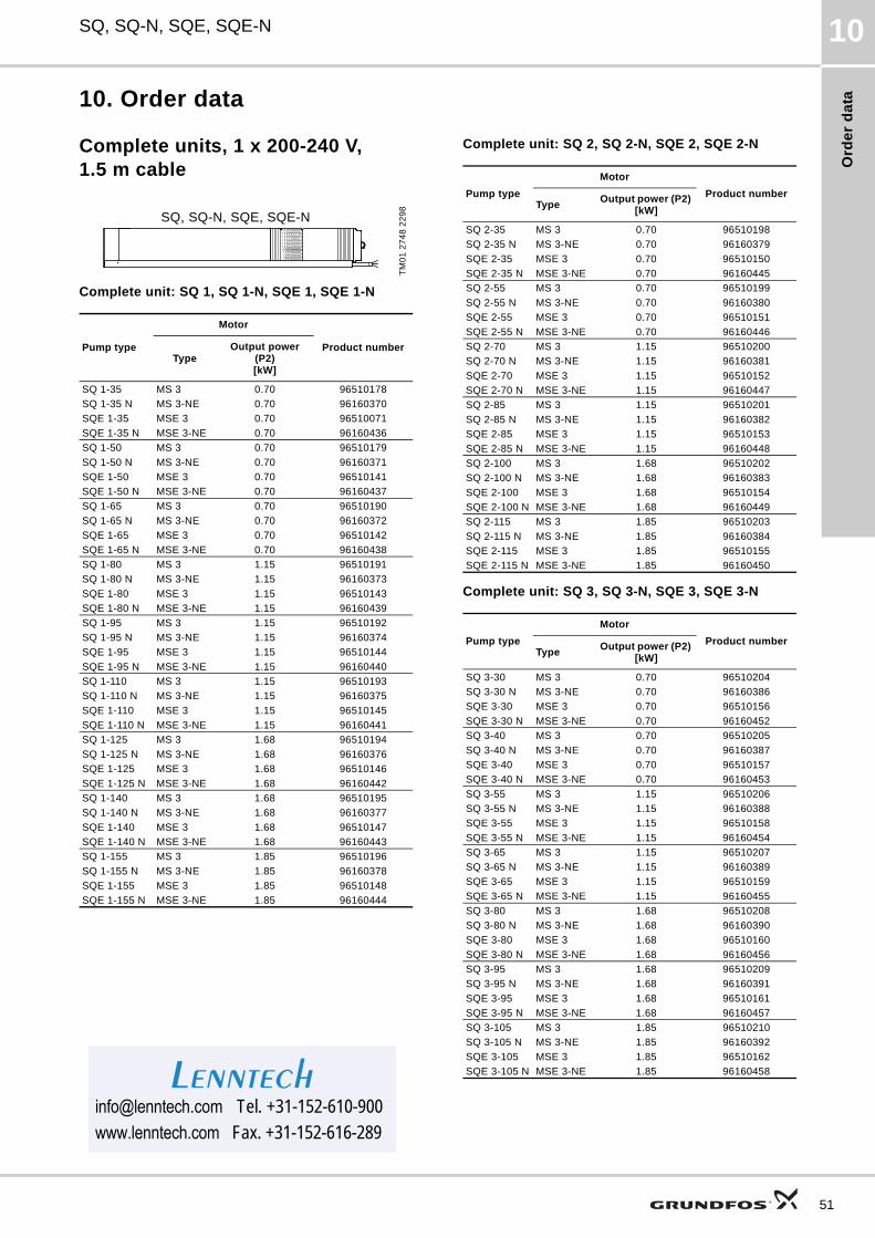
Ord
er
da
ta
SQ, SQ-N, SQE, SQE-N 10
10. Order data
Complete units, 1 x 200-240 V, 1.5 m cable
Complete unit: SQ 1, SQ 1-N, SQE 1, SQE 1-N
Complete unit: SQ 2, SQ 2-N, SQE 2, SQE 2-N
Complete unit: SQ 3, SQ 3-N, SQE 3, SQE 3-N
TM
01
27
48
22
98
Pump type
Motor
Product numberType
Output power(P2)[kW]
SQ 1-35 MS 3 0.70 96510178
SQ 1-35 N MS 3-NE 0.70 96160370
SQE 1-35 MSE 3 0.70 96510071
SQE 1-35 N MSE 3-NE 0.70 96160436
SQ 1-50 MS 3 0.70 96510179
SQ 1-50 N MS 3-NE 0.70 96160371
SQE 1-50 MSE 3 0.70 96510141
SQE 1-50 N MSE 3-NE 0.70 96160437
SQ 1-65 MS 3 0.70 96510190
SQ 1-65 N MS 3-NE 0.70 96160372
SQE 1-65 MSE 3 0.70 96510142
SQE 1-65 N MSE 3-NE 0.70 96160438
SQ 1-80 MS 3 1.15 96510191
SQ 1-80 N MS 3-NE 1.15 96160373
SQE 1-80 MSE 3 1.15 96510143
SQE 1-80 N MSE 3-NE 1.15 96160439
SQ 1-95 MS 3 1.15 96510192
SQ 1-95 N MS 3-NE 1.15 96160374
SQE 1-95 MSE 3 1.15 96510144
SQE 1-95 N MSE 3-NE 1.15 96160440
SQ 1-110 MS 3 1.15 96510193
SQ 1-110 N MS 3-NE 1.15 96160375
SQE 1-110 MSE 3 1.15 96510145
SQE 1-110 N MSE 3-NE 1.15 96160441
SQ 1-125 MS 3 1.68 96510194
SQ 1-125 N MS 3-NE 1.68 96160376
SQE 1-125 MSE 3 1.68 96510146
SQE 1-125 N MSE 3-NE 1.68 96160442
SQ 1-140 MS 3 1.68 96510195
SQ 1-140 N MS 3-NE 1.68 96160377
SQE 1-140 MSE 3 1.68 96510147
SQE 1-140 N MSE 3-NE 1.68 96160443
SQ 1-155 MS 3 1.85 96510196
SQ 1-155 N MS 3-NE 1.85 96160378
SQE 1-155 MSE 3 1.85 96510148
SQE 1-155 N MSE 3-NE 1.85 96160444
SQ, SQ-N, SQE, SQE-N
Pump type
Motor
Product numberType
Output power (P2) [kW]
SQ 2-35 MS 3 0.70 96510198
SQ 2-35 N MS 3-NE 0.70 96160379
SQE 2-35 MSE 3 0.70 96510150
SQE 2-35 N MSE 3-NE 0.70 96160445
SQ 2-55 MS 3 0.70 96510199
SQ 2-55 N MS 3-NE 0.70 96160380
SQE 2-55 MSE 3 0.70 96510151
SQE 2-55 N MSE 3-NE 0.70 96160446
SQ 2-70 MS 3 1.15 96510200
SQ 2-70 N MS 3-NE 1.15 96160381
SQE 2-70 MSE 3 1.15 96510152
SQE 2-70 N MSE 3-NE 1.15 96160447
SQ 2-85 MS 3 1.15 96510201
SQ 2-85 N MS 3-NE 1.15 96160382
SQE 2-85 MSE 3 1.15 96510153
SQE 2-85 N MSE 3-NE 1.15 96160448
SQ 2-100 MS 3 1.68 96510202
SQ 2-100 N MS 3-NE 1.68 96160383
SQE 2-100 MSE 3 1.68 96510154
SQE 2-100 N MSE 3-NE 1.68 96160449
SQ 2-115 MS 3 1.85 96510203
SQ 2-115 N MS 3-NE 1.85 96160384
SQE 2-115 MSE 3 1.85 96510155
SQE 2-115 N MSE 3-NE 1.85 96160450
Pump type
Motor
Product numberType
Output power (P2) [kW]
SQ 3-30 MS 3 0.70 96510204
SQ 3-30 N MS 3-NE 0.70 96160386
SQE 3-30 MSE 3 0.70 96510156
SQE 3-30 N MSE 3-NE 0.70 96160452
SQ 3-40 MS 3 0.70 96510205
SQ 3-40 N MS 3-NE 0.70 96160387
SQE 3-40 MSE 3 0.70 96510157
SQE 3-40 N MSE 3-NE 0.70 96160453
SQ 3-55 MS 3 1.15 96510206
SQ 3-55 N MS 3-NE 1.15 96160388
SQE 3-55 MSE 3 1.15 96510158
SQE 3-55 N MSE 3-NE 1.15 96160454
SQ 3-65 MS 3 1.15 96510207
SQ 3-65 N MS 3-NE 1.15 96160389
SQE 3-65 MSE 3 1.15 96510159
SQE 3-65 N MSE 3-NE 1.15 96160455
SQ 3-80 MS 3 1.68 96510208
SQ 3-80 N MS 3-NE 1.68 96160390
SQE 3-80 MSE 3 1.68 96510160
SQE 3-80 N MSE 3-NE 1.68 96160456
SQ 3-95 MS 3 1.68 96510209
SQ 3-95 N MS 3-NE 1.68 96160391
SQE 3-95 MSE 3 1.68 96510161
SQE 3-95 N MSE 3-NE 1.68 96160457
SQ 3-105 MS 3 1.85 96510210
SQ 3-105 N MS 3-NE 1.85 96160392
SQE 3-105 MSE 3 1.85 96510162
SQE 3-105 N MSE 3-NE 1.85 [email protected] Tel. +31-152-610-900www.lenntech.com Fax. [email protected] Tel. +31-152-610-900www.lenntech.com Fax. +31-152-616-289
Lenntech
51
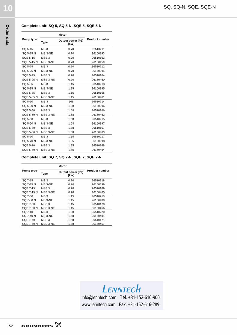
Ord
er d
ata
52
SQ, SQ-N, SQE, SQE-N10
Complete unit: SQ 5, SQ 5-N, SQE 5, SQE 5-N
Complete unit: SQ 7, SQ 7-N, SQE 7, SQE 7-N
Pump type
Motor
Product numberType
Output power (P2) [kW]
SQ 5-15 MS 3 0.70 96510211
SQ 5-15 N MS 3-NE 0.70 96160393
SQE 5-15 MSE 3 0.70 96510163
SQE 5-15 N MSE 3-NE 0.70 96160459
SQ 5-25 MS 3 0.70 96510212
SQ 5-25 N MS 3-NE 0.70 96160394
SQE 5-25 MSE 3 0.70 96510164
SQE 5-25 N MSE 3-NE 0.70 96160460
SQ 5-35 MS 3 1.15 96510213
SQ 5-35 N MS 3-NE 1.15 96160395
SQE 5-35 MSE 3 1.15 96510165
SQE 5-35 N MSE 3-NE 1.15 96160461
SQ 5-50 MS 3 168 96510214
SQ 5-50 N MS 3-NE 1.68 96160396
SQE 5-50 MSE 3 1.68 96510166
SQE 5-50 N MSE 3-NE 1.68 96160462
SQ 5-60 MS 3 1.68 96510215
SQ 5-60 N MS 3-NE 1.68 96160397
SQE 5-60 MSE 3 1.68 96510167
SQE 5-60 N MSE 3-NE 1.68 96160463
SQ 5-70 MS 3 1.85 96510217
SQ 5-70 N MS 3-NE 1.85 96160398
SQE 5-70 MSE 3 1.85 96510168
SQE 5-70 N MSE 3-NE 1.85 96160464
Pump type
Motor
Product numberType
Output power (P2) [kW]
SQ 7-15 MS 3 0.70 96510218
SQ 7-15 N MS 3-NE 0.70 96160399
SQE 7-15 MSE 3 0.70 96510169
SQE 7-15 N MSE 3-NE 0.70 96160465
SQ 7-30 MS 3 1.15 96510219
SQ 7-30 N MS 3-NE 1.15 96160400
SQE 7-30 MSE 3 1.15 96510170
SQE 7-30 N MSE 3-NE 1.15 96160466
SQ 7-40 MS 3 1.68 96510220
SQ 7-40 N MS 3-NE 1.68 96160401
SQE 7-40 MSE 3 1.68 96510171
SQE 7-40 N MSE 3-NE 1.68 96160467
[email protected] Tel. +31-152-610-900www.lenntech.com Fax. [email protected] Tel. +31-152-610-900www.lenntech.com Fax. +31-152-616-289
Lenntech
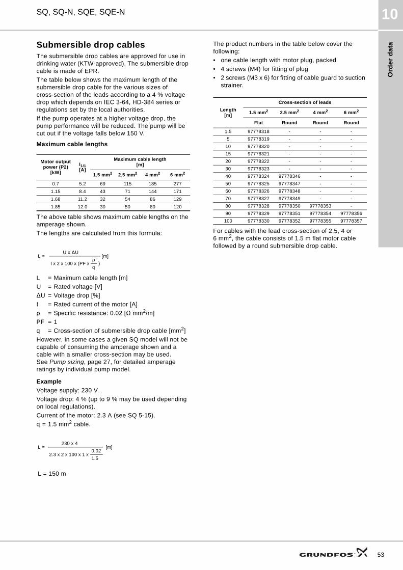
Ord
er
da
ta
SQ, SQ-N, SQE, SQE-N 10
Submersible drop cablesThe submersible drop cables are approved for use in drinking water (KTW-approved). The submersible drop cable is made of EPR.
The table below shows the maximum length of the submersible drop cable for the various sizes of cross-section of the leads according to a 4 % voltage drop which depends on IEC 3-64, HD-384 series or regulations set by the local authorities.
If the pump operates at a higher voltage drop, the pump performance will be reduced. The pump will be cut out if the voltage falls below 150 V.
Maximum cable lengths
The above table shows maximum cable lengths on the amperage shown.
The lengths are calculated from this formula:
L = Maximum cable length [m]
U = Rated voltage [V]
ΔU = Voltage drop [%]
I = Rated current of the motor [A]
ρ = Specific resistance: 0.02 [Ω mm2/m]
PF = 1
q = Cross-section of submersible drop cable [mm2]
However, in some cases a given SQ model will not be capable of consuming the amperage shown and a cable with a smaller cross-section may be used. See Pump sizing, page 27, for detailed amperage ratings by individual pump model.
Example
Voltage supply: 230 V.
Voltage drop: 4 % (up to 9 % may be used depending on local regulations).
Current of the motor: 2.3 A (see SQ 5-15).
q = 1.5 mm2 cable.
The product numbers in the table below cover the following:
• one cable length with motor plug, packed
• 4 screws (M4) for fitting of plug
• 2 screws (M3 x 6) for fitting of cable guard to suction strainer.
For cables with the lead cross-section of 2.5, 4 or 6 mm2, the cable consists of 1.5 m flat motor cable followed by a round submersible drop cable.
Motor output power (P2)
[kW]
I1/1[A]
Maximum cable length[m]
1.5 mm2 2.5 mm2 4 mm2 6 mm2
0.7 5.2 69 115 185 277
1.15 8.4 43 71 144 171
1.68 11.2 32 54 86 129
1.85 12.0 30 50 80 120
L = [m] U x ΔU
I x 2 x 100 x (PF xρ
)q
L = [m] 230 x 4
2.3 x 2 x 100 x 1 x0.02
1.5
L = 150 m
Length[m]
Cross-section of leads
1.5 mm2 2.5 mm2 4 mm2 6 mm2
Flat Round Round Round
1.5 97778318 - - -
5 97778319 - - -
10 97778320 - - -
15 97778321 - - -
20 97778322 - - -
30 97778323 - - -
40 97778324 97778346 - -
50 97778325 97778347 - -
60 97778326 97778348 - -
70 97778327 97778349 - -
80 97778328 97778350 97778353 -
90 97778329 97778351 97778354 97778356
100 97778330 97778352 97778355 97778357
53
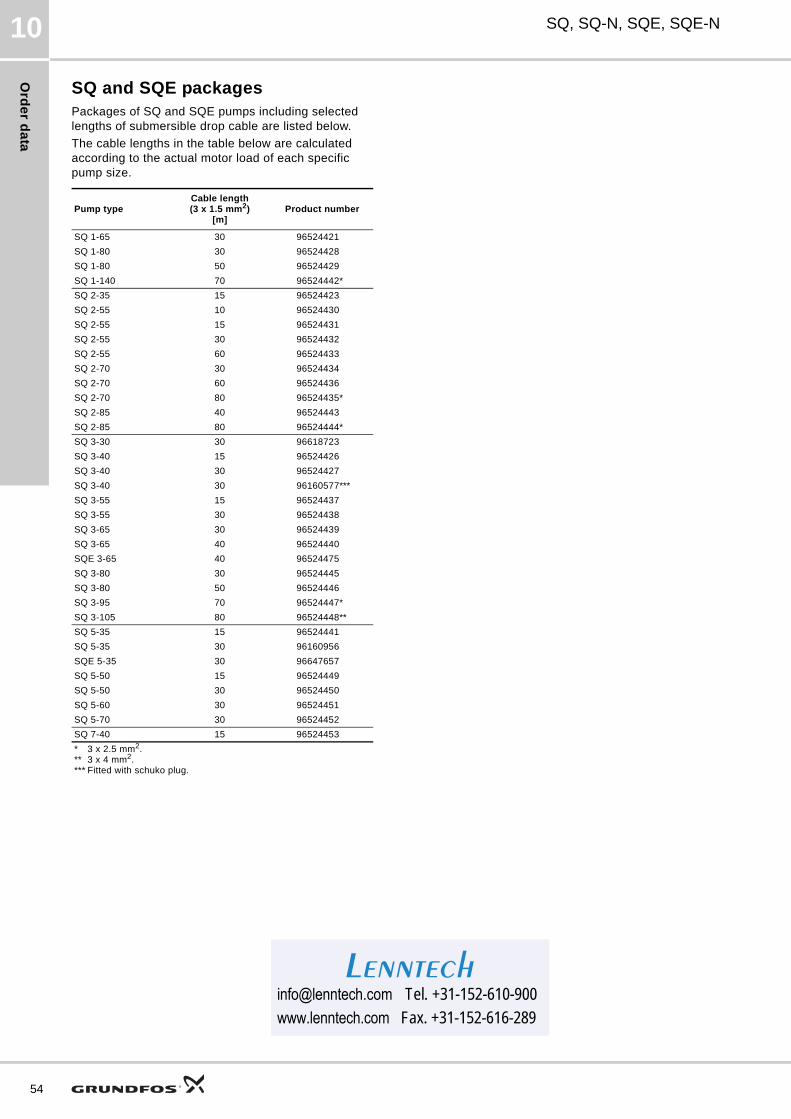
Ord
er d
ata
54
SQ, SQ-N, SQE, SQE-N10
SQ and SQE packagesPackages of SQ and SQE pumps including selected lengths of submersible drop cable are listed below.
The cable lengths in the table below are calculated according to the actual motor load of each specific pump size.
Pump typeCable length(3 x 1.5 mm2)
[m]Product number
SQ 1-65 30 96524421
SQ 1-80 30 96524428
SQ 1-80 50 96524429
SQ 1-140 70 96524442*
SQ 2-35 15 96524423
SQ 2-55 10 96524430
SQ 2-55 15 96524431
SQ 2-55 30 96524432
SQ 2-55 60 96524433
SQ 2-70 30 96524434
SQ 2-70 60 96524436
SQ 2-70 80 96524435*
SQ 2-85 40 96524443
SQ 2-85 80 96524444*
SQ 3-30 30 96618723
SQ 3-40 15 96524426
SQ 3-40 30 96524427
SQ 3-40 30 96160577***
SQ 3-55 15 96524437
SQ 3-55 30 96524438
SQ 3-65 30 96524439
SQ 3-65 40 96524440
SQE 3-65 40 96524475
SQ 3-80 30 96524445
SQ 3-80 50 96524446
SQ 3-95 70 96524447*
SQ 3-105 80 96524448**
SQ 5-35 15 96524441
SQ 5-35 30 96160956
SQE 5-35 30 96647657
SQ 5-50 15 96524449
SQ 5-50 30 96524450
SQ 5-60 30 96524451
SQ 5-70 30 96524452
SQ 7-40 15 96524453
* 3 x 2.5 mm2.** 3 x 4 mm2.*** Fitted with schuko plug.
[email protected] Tel. +31-152-610-900www.lenntech.com Fax. [email protected] Tel. +31-152-610-900www.lenntech.com Fax. +31-152-616-289
Lenntech
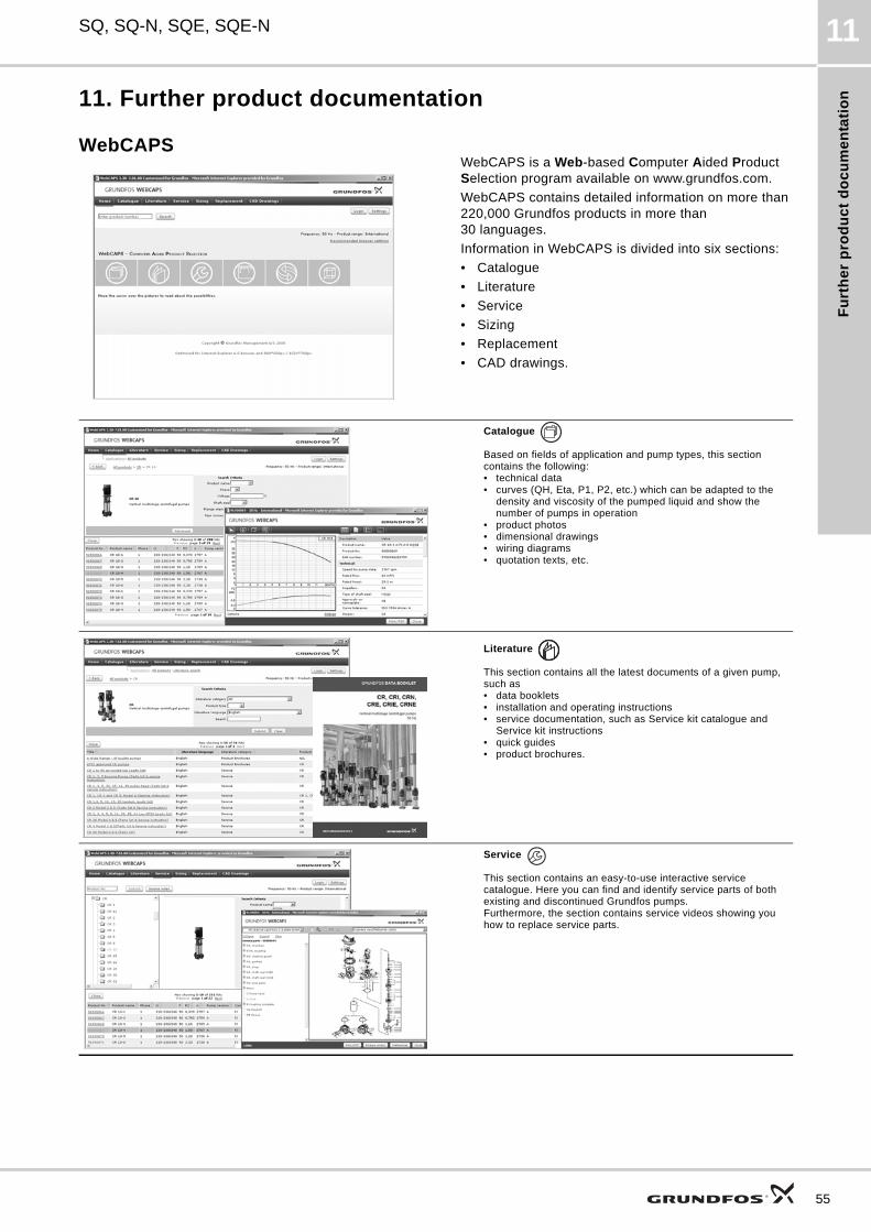
Fu
rth
er
pro
du
ct
do
cu
me
nta
tio
n
SQ, SQ-N, SQE, SQE-N 11
11. Further product documentation
WebCAPSWebCAPS is a Web-based Computer Aided Product Selection program available on www.grundfos.com.
WebCAPS contains detailed information on more than 220,000 Grundfos products in more than 30 languages.
Information in WebCAPS is divided into six sections:
• Catalogue
• Literature
• Service
• Sizing
• Replacement
• CAD drawings.
Catalogue
Based on fields of application and pump types, this section contains the following:• technical data• curves (QH, Eta, P1, P2, etc.) which can be adapted to the
density and viscosity of the pumped liquid and show the number of pumps in operation
• product photos• dimensional drawings• wiring diagrams• quotation texts, etc.
Literature
This section contains all the latest documents of a given pump, such as• data booklets• installation and operating instructions• service documentation, such as Service kit catalogue and
Service kit instructions• quick guides• product brochures.
Service
This section contains an easy-to-use interactive service catalogue. Here you can find and identify service parts of both existing and discontinued Grundfos pumps.Furthermore, the section contains service videos showing you how to replace service parts.
55
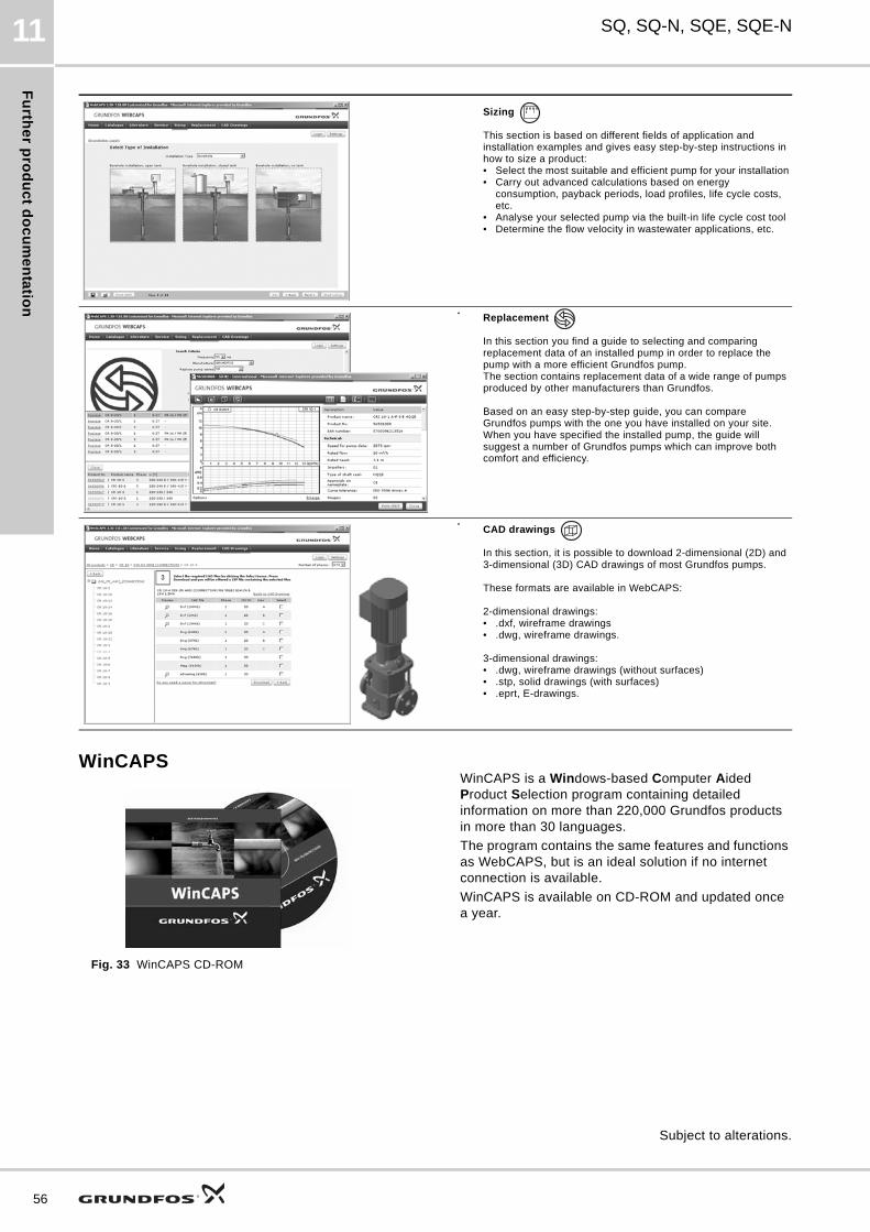
Fu
rthe
r pro
du
ct d
oc
um
en
tatio
n
56
SQ, SQ-N, SQE, SQE-N11
WinCAPS
Fig. 33 WinCAPS CD-ROM
WinCAPS is a Windows-based Computer Aided Product Selection program containing detailed information on more than 220,000 Grundfos products in more than 30 languages.
The program contains the same features and functions as WebCAPS, but is an ideal solution if no internet connection is available.
WinCAPS is available on CD-ROM and updated once a year.
Sizing
This section is based on different fields of application and installation examples and gives easy step-by-step instructions in how to size a product:• Select the most suitable and efficient pump for your installation• Carry out advanced calculations based on energy
consumption, payback periods, load profiles, life cycle costs, etc.
• Analyse your selected pump via the built-in life cycle cost tool• Determine the flow velocity in wastewater applications, etc.
Replacement
In this section you find a guide to selecting and comparing replacement data of an installed pump in order to replace the pump with a more efficient Grundfos pump. The section contains replacement data of a wide range of pumps produced by other manufacturers than Grundfos.
Based on an easy step-by-step guide, you can compare Grundfos pumps with the one you have installed on your site. When you have specified the installed pump, the guide will suggest a number of Grundfos pumps which can improve both comfort and efficiency.
CAD drawings
In this section, it is possible to download 2-dimensional (2D) and 3-dimensional (3D) CAD drawings of most Grundfos pumps.
These formats are available in WebCAPS:
2-dimensional drawings:• .dxf, wireframe drawings• .dwg, wireframe drawings.
3-dimensional drawings:• .dwg, wireframe drawings (without surfaces)• .stp, solid drawings (with surfaces)• .eprt, E-drawings.
0 1
Subject to alterations.

The name Grundfos, the Grundfos logo, and the payoff Be–Think–Innovate are registrated trademarks owned by Grundfos Management A/S or Grundfos A/S, Denmark. All rights reserved worldwide.
Being responsible is our foundationThinking ahead makes it possible
Innovation is the essence
V7141076 1011 GBRepl. V7141076 0507
ECM: 1080125
Lenntech
[email protected] Tel. +31-152-610-900www.lenntech.com Fax. [email protected] Tel. +31-152-610-900www.lenntech.com Fax. +31-152-616-289
Lenntech
Recommended