Electromagnetism

Magnetic Fields
• Magnetic field: a region where another magnet (or magnetic material) feels a force
• Field lines show direction of force on a N pole
• Magnetic field strength aka Magnetic Flux density, B– A vector quantity– unit: Tesla– Indicated by density of field lines

•Direction of field given by Maxwell’s Right Hand grip rule (or think of a screw thread).
Reminder: Magnetic field around a wire carrying current
A reminder of some B fields

Magnetic force on moving charges
• An electrical charge moving in a magnetic field experiences a force.
• This is true for electrons moving in a wire in a magnetic field – the motor effect.– Demo
Motio
n
FieldCur
ren
t
“Fleming’s Left Hand Rule”

N S
Motor Effect Questions
•A wire carries a current horizontally between the poles of a magnet, as shown below. The direction of the force on the wire is:•A from N to S•B from S to N•C opposite to the current direction•D In the direction of the current•E vertically upwards?
current
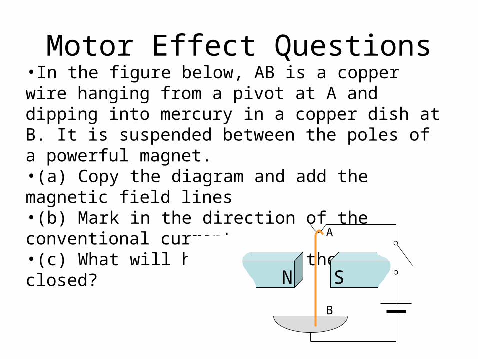
Motor Effect Questions•In the figure below, AB is a copper wire hanging from a pivot at A and dipping into mercury in a copper dish at B. It is suspended between the poles of a powerful magnet. •(a) Copy the diagram and add the magnetic field lines•(b) Mark in the direction of the conventional current•(c) What will happen when the switch is closed?
N S
A
B

Force on a current-carrying wire
• Do the Experiment
Force on a current-carrying wire
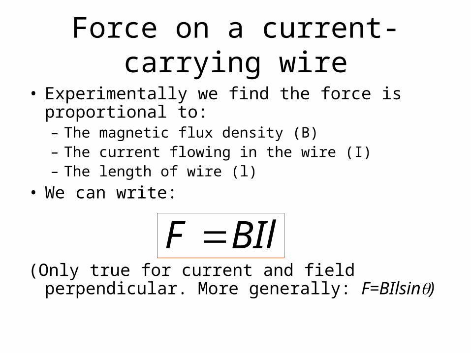
• Experimentally we find the force is proportional to:– The magnetic flux density (B)– The current flowing in the wire (I)– The length of wire (l)
• We can write:
(Only true for current and field perpendicular. More generally: F=BIlsin)
BIlF

Definition of the Tesla
• 1T is defined as the magnetic flux density which produces a force of 1N on a 1m length of wire carrying a current of 1A at right angles to the field.
• 1T=1 NA-1m-1

Definition of the Ampere
• Parallel wires carrying currents will exert forces on each other. – Each wire produces a magnetic
field, which influences the other wire.
• The ampere is defined as the constant current which, if flowing in two straight parallel conductors placed 1 metre apart in a vacuum, would produce between these conductors a force equal to 2×10⁻⁷ newtons per metre of length
[Not examinable]
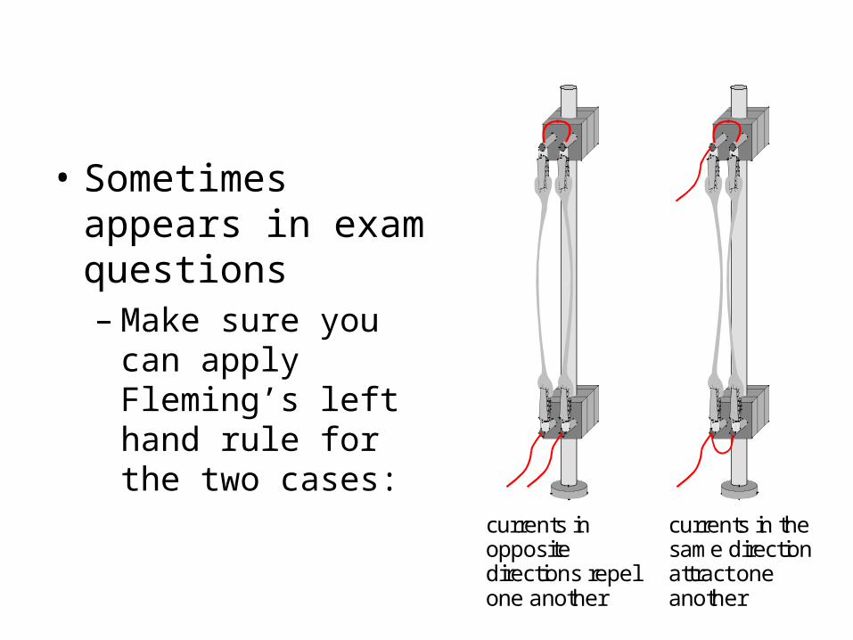
• Sometimes appears in exam questions– Make sure you can
apply Fleming’s left hand rule for the two cases:
currents inoppositedirections repelone another
currents in thesame directionattract oneanother
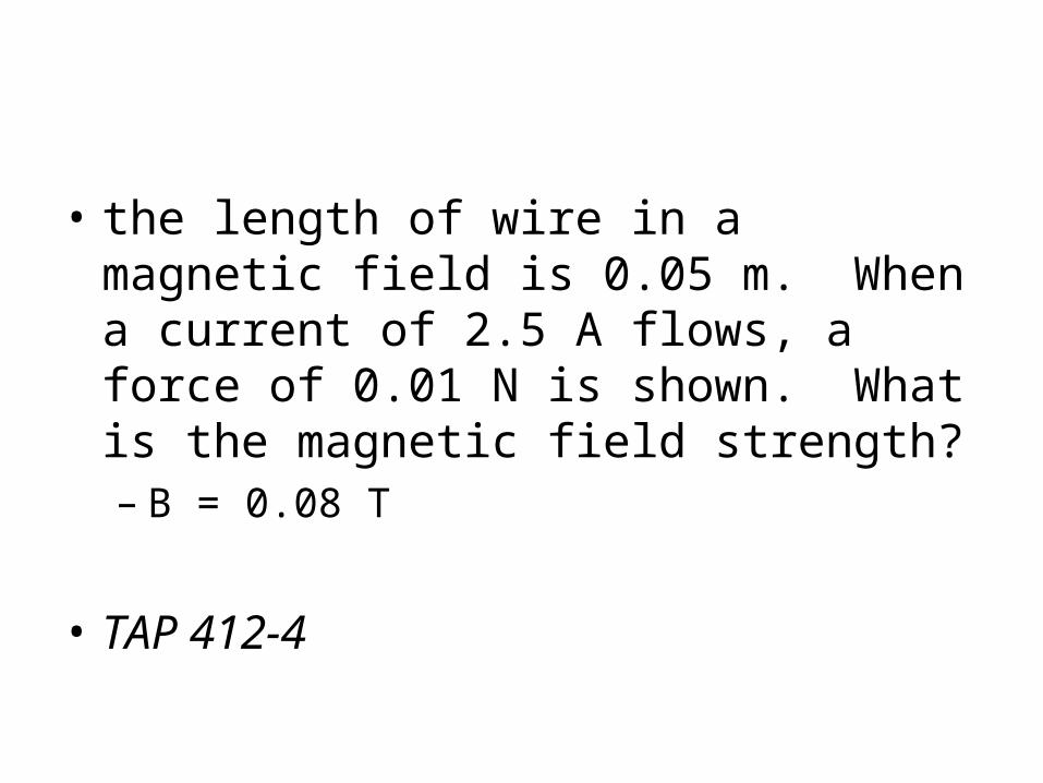
• the length of wire in a magnetic field is 0.05 m. When a current of 2.5 A flows, a force of 0.01 N is shown. What is the magnetic field strength? – B = 0.08 T
• TAP 412-4


Couple on a coil
• Force on each side of coil with n turns: F=BILn
• Pair of forces form a couple• Torque of couple=Force x
distance between them
• But when coil is not perpendicular to field, the effective width is wcos
BILnwT
w
B
cos
so ,
cos
BIAnT
ALw
BILnwT

Electric motor
DC Motor AC Motor

Force on a moving charge
• Consider a charge Q moving at a speed v:
BQvF
vtt
QBBIlF
vtlt
lv
t
QI
..
so
Force always 90° to velocity – circular motion

• An electron accelerated to 6.0 × 10⁶ ms–1 is deflected by a magnetic field of strength 0.82 T. What is the force acting on the electron? Would it be any different for a proton?F= –7.9 10–13 N – The value of the force would be the same but
the direction would be opposite.

The Hall Probe• Used to measure magnetic
field strength– Current flows through a
slice of semiconductor– Force on moving charges
due to magnetic field deflects charges
– Potential difference between top and bottom of slice results
– Hall voltage B field strength


• An electron passes through a cathode ray tube with a velocity of 3.7 × 10⁷ m/s. It enters a magnetic field of flux density 0.47 mT at a right angle. What is the radius of curvature of the path in the magnetic field?– F = Bqv and F = mv2/r so r=mv/Bq– r=44 cm
• Note that radius of track depends on the charge/mass ratio of particles
• This is how a mass spectrometer works…

Velocity selector
• Force on ions due to electric field
• Force on ions due to magnetic field
• Only particles with certain velocity so forces cancel can pass through
d
QVFelec
BQvFmag
Bd
Vv

Mass SpectrometerVelocity selector• It can be shown that only
particles with velocity v=E/B pass through the velocity selector
• R=mv/qB=mE/qB2
• If we know the charge (ionisation state), we can find the mass of the particles from the radius of their path
• This enables us to analyse the constituents of complex materials.

Application: cyclotron
• A cyclotron is a compact particle accelerator

Lawrence’s Cyclotron
• Particles are repeatedly accelerated when passing between “dees”– Velocity increases– Radius increases
• Time for an orbit remains constant– Constant frequency
drive signal Bq
m
v
rt
Bq
mvr semiorbit
so,

The first Cyclotron
Accelerated protons to 80keV

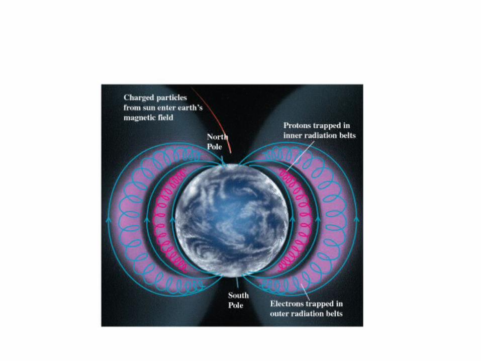
Electromagnetic induction
• Any conductor experiencing a changing magnetic field (or moving across a steady magnetic field) will have a p.d. induced across it.
• If a closed circuit is made, a current will flow.
• This is the basis of almost all electricity generation.
1820 – Ørsted discovers B field of current
1831 – Faraday discovers induction

The right hand rule
• Not to be confused with the left hand rule...

Electromagnetic induction

Electromagnetic induction
• The direction of the induced voltage can be reversed by:– Reversing the magnet– Moving the magnet in the opposite direction

Electromagnetic induction
• The size of the induced voltage can be increased by:– Moving the magnet faster– Increasing the number of turns on the coil– Using a stronger magnet
• Adding a soft iron core

Magnetic Flux
• A useful quantity when considering electromagnetic induction
• =BA if area is at 90° to field (=BAcos otherwise)
• (Loosely) total magnetic field experienced by something of a given area
AB.Flux Flux density
area
Unit: Weber (Wb)
1 Wb = 1T x 1 m2
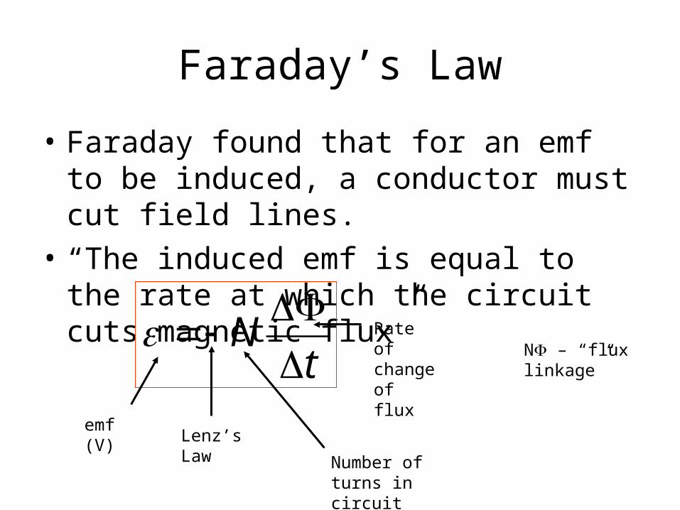
Faraday’s Law
• Faraday found that for an emf to be induced, a conductor must cut field lines.
• “The induced emf is equal to the rate at which the circuit cuts magnetic flux”
tN
emf (V)
Rate of change of flux
Lenz’s Law
Number of turns in circuit
N – “flux linkage”

Lenz’s Law
• The direction of the induced emf is always such that it opposes the change inducing it– Really just the principle of conservation of
energy– What would happen if it did not oppose it?
• Denoted by the minus sign in the formula.
• Induction demos, 414-11 (diff tubes?)• Magnet falling through a coil


Generating electricity
• Consider a conducting rod of length L moving at a steady speed v perpendicular to a field with a flux density B:
• electrons will experience a force Bev along the rod, creating a separation of charge
• Electrostatic repulsion opposes this.
Flux density (B)
v
L
BLv
BvLVE
veBeE
/
Induced emf

Flux density (B)
v
L
• Note: – area A swept out in time t = Lvt, so:
Faraday’s Law
“emf=flux swept out per second”
How to increase ?
BLv
tt
BAt
tBLv

Calculate...
70°
North
Earth’sB-field
– +

Faraday’s disc
• When the disc turns at frequency f an emf is induced between its axle and rim
• Think of a thin strip:
• Flux swept out/s=
=BR2f
• With a load have braking system

Windmills
• The blade of a wind turbine has a radius 12 m and rotates every 6 seconds. The turbine’s axis is aligned N-S, so the blade cuts the horizontal component of the Earth’s magnetic field, which is 20 T.
• Calculate the emf induced across the blade.
• Flux swept out/s==BR2f=0.0015V
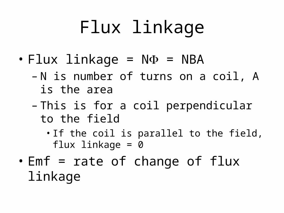
Flux linkage
• Flux linkage = N = NBA– N is number of turns on a coil, A is the area– This is for a coil perpendicular to the field
• If the coil is parallel to the field, flux linkage = 0
• Emf = rate of change of flux linkage

Generators / dynamos
• To generate a continuous voltage we need a constantly changing magnetic field.
• This is achieved by rotating a magnet in or near a coil of wire.
• An ALTERNATING
CURRENT is produced.

Alternating output
Magnet position

Dynamos

More usually...
• AC generator is a coil rotating in a magnetic field
• AC motor run in reverse...
peak =BAN
Figure 1(a)
time
e.m.f
a.coutput
Figure 1(c)
brushes
magnetslip rings
coil
Figure 1(b)

AC generation
• Flux linkage through coil:
• If the coil is spun with an angular frequency :
cosBANN
)cos( so ,2 tBANNtft
)sin( tBANdt
dN
)sin( so , 00 tBAN
Induced emf=0 when coil edges moving parallel to B field
Induced emf is max/min when coil edges cut perpendicularly across B field
How would you design a higher voltage generator?
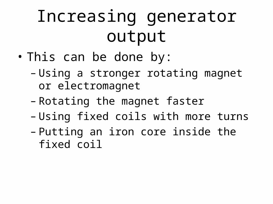
Increasing generator output
• This can be done by:– Using a stronger rotating magnet or
electromagnet– Rotating the magnet faster– Using fixed coils with more turns– Putting an iron core inside the fixed coil

Real generators


Battersea Power Station, 1933
Mutual induction
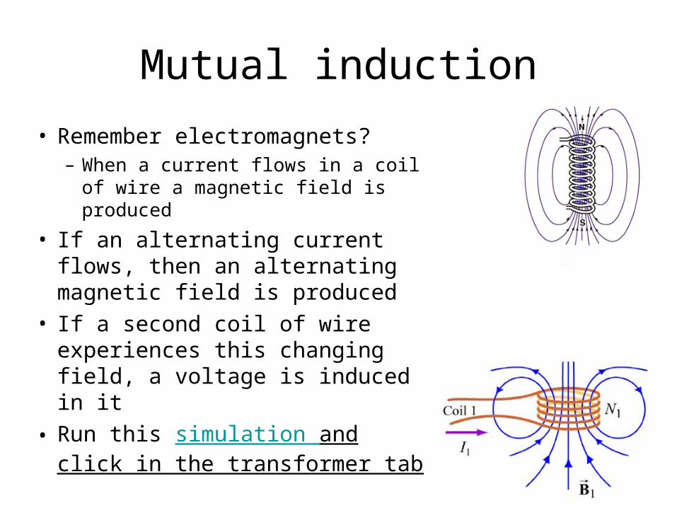
• Remember electromagnets?– When a current flows in a coil of
wire a magnetic field is produced
• If an alternating current flows, then an alternating magnetic field is produced
• If a second coil of wire experiences this changing field, a voltage is induced in it
• Run this simulation and click in the transformer tab

Transformers• A transformer consists of
two coil mounted on a common iron core
• An alternating current flowing in the primary coil induces a changing magnetic field
• The iron core concentrates the field through the centre of the secondary coil
• The alternating magnetic field induces an alternating current in the secondary coil
• This happens even though there is no direct electrical connection between the two coils

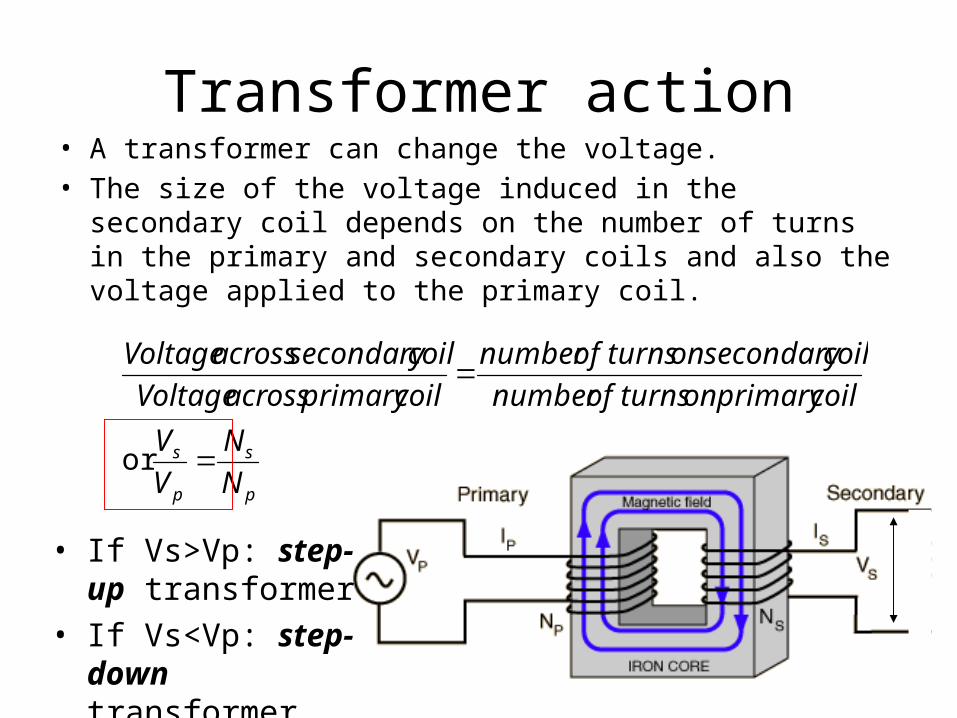
Transformer action• A transformer can change the voltage.• The size of the voltage induced in the secondary coil depends
on the number of turns in the primary and secondary coils and also the voltage applied to the primary coil.
• If Vs>Vp: step-up transformer
• If Vs<Vp: step-down transformer
p
s
p
s
N
N
V
V
or
coil primary on turns of numbercoil secondary on turns of number
coil primary across Voltagecoil secondary across Voltage
Transformer example
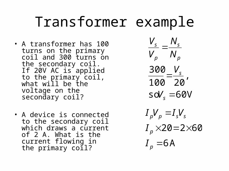
• A transformer has 100 turns on the primary coil and 300 turns on the secondary coil. If 20V AC is applied to the primary coil, what will be the voltage on the secondary coil?
• A device is connected to the secondary coil which draws a current of 2 A. What is the current flowing in the primary coil?
V 60 so
,20100
300
s
s
p
s
p
s
V
V
N
N
V
V
A 6
60220
p
p
sspp
I
I
VIVI

Transformer efficiency
• Transformers can be close to 100% efficient through the use of:– Low resistance windings– A laminated iron core to reduce eddy currents– Using soft iron to minimise magnetisation
losses
100coilprimary by suppliedpower
coilsecondary by deliveredpower efficiency
pp
ss
VI
VI

Power in a transformer
• So if a transformer steps up the voltage, the current is stepped down.– You can’t get something for nothing!
• This assumes an ideal transformer, where no energy is lost to heating
sspp VIVI
so
outPower in Power

Electricity transmission• When electricity is transmitted over
power lines, some power is lost due to the resistance of the cables (as heat)
• P = IV and V=IR so Power lost = I2R– So the higher the current, the more
power we lose• A step-up transformer is used to
convert electrical power to very high voltage (low current) for transmission over long distances to minimise this power loss
• It is converted back to a more useful level at the other end by a step-down transformer

Typical power transmission system
Recommended


![Magnetic Rendering: Magnetic Field Control for …...force magnetic levitation devices [10], in which the articulated arm is replace by magnetic force. Because this method provides](https://img.dokumen.tips/doc/110x75/5f6e08c876a88600bc67fcf7/magnetic-rendering-magnetic-field-control-for-force-magnetic-levitation-devices.jpg)