QBX PRESSURE Vacuum to 175 psig
FLOW Up to 1.2 scfm
ACCURACY +/- 0.2% full scale
Up to 12 bar & 34 Lit/Min
On-Board Ethernet Option
QBS PRESSURE Vacuum to 500 psig
FLOW Up to 1.2 scfm
ACCURACY +/- 0.5% full scale
Up to 34 bar & 34 Lit/Min
High Pressure Control
ELECTRO-PNEUMATIC PRESSURE REGULATORS
QBT PRESSURE Vacuum to 175 psig
FLOW Up to 1.2 scfm
ACCURACY +/- 0.2% full scale
Up to 12 bar & 34 Lit/Min
Accurate & Repeatable

2 BRQB041406E * PROPORTION-AIR * LET’S TALK 317-335-2602
2 BRQBO4-2017 PROPORTION-AIR.COM * LET’S TALK: 317.335.2602 | 877.331.1738
FUNCTIONAL DESCRIPTION of the QB-Series
The QB Series uses Proportion-Air’s patented
technology for closed loop control. The QB Series valves
can be built in either a single loop or double loop control
scheme.
The QBT Series is used to control pressure of inert
gases from full vacuum up to 175 psig (12 bar).
The QBS is used in applications where the maximum
calibrated pressure ranges are between 175 and 500 psig
(34 bar). The QBS Series can also be used in
applications where the pressure ranges are below 175
psig (12 bar) if the wetted parts on the QBS are
compatible with the media being controlled. The QBS
Series uses a solid one piece manifold for added
strength, available in anodized aluminum or stainless
steel. There are two outlet ports which allows flexibility in
mounting options. In all QBS models, a stainless steel
pressure sensor that utilizes dry technology instead of liquid
fill, is used internally for increased reliability and enhanced
media compatibility.
THEORY OF OPERATION
The QB1 is a single loop model consisting of
valves, manifold, internal pressure transducer, and
electronic controls. Output pressure is proportional to an
electrical signal input. Pressure is controlled by two
solenoid valves. One valve functions as the inlet control,
the other as exhaust. The pressure output is measured
by a pressure transducer internal to the QB1 and
provides a feedback signal to the electronic controls.
This feedback signal is compared against the command
signal input. A difference between the two signals causes
one of the solenoid valves to open allowing flow in or out
of the system. Accurate pressure is maintained by
controlling these two valves.
COMMAND SIGNAL
Command inputs come in a choice of either 0 to 10
Vdc, 4 to 20mA, Modbus or Ethernet (QBX only).
MONITOR SIGNAL
All QB’s come with a 0-10 volt or an optional 4-20mA
monitor signal for output to a panel meter or controller for
data acquisition or quality assurance needs. On a QB1,
the monitor signal represents the internal pressure
transducer that is measuring the work pressure. On a
QB2, the monitor signal represents the signal from the
external sensor that is monitoring the output downstream.
The QB2 is similar to the QB1 but uses a double loop
control scheme. In addition to the internal pressure
transducer, the QB2 also receives a feedback signal from
an external sensing device. The external signal functions
as the primary feedback signal which is compared against
the command signal input. This outer loop comparison is
then used to provide a command to the inner loop. A
difference between the two comparisons causes one of
the solenoid valves to open allowing flow in or out of the
system.
Since the external feedback signal is electrical, control
is not limited to pressure. Using other types of sensors
allows control over parameters such as force, position,
flow, etc. Usually in these applications the QB2 valve
functions as pilot to a slave regulator controlling the end
result. With a sensor providing system feedback, the
package becomes a closed loop control system.
The QB control valve is specified as a stand alone
valve in static applications with low flow requirements. It
can also be used as a pilot to air piloted regulators
(volume boosters) in applications where the flow rate of
the controlled pressure is higher than QB’s flow rate.

LET’S TALK 317-335-2602 * PROPORTION-AIR * BRQB041406E 3 BRQBO4-2017 * PROPORTION-AIR.COM * LET’S TALK: 317.335.2602 | 877.331.1738 3
PERFORMANCE CHARACTERISTICS
This chart shows the linear characteristics of QB products when given a ramp signal from 0 to 10 volts. Characteristics would be similar for 4 to 20 mA units.
LINEARITY
0 1 2 3 4 5 6 7 8 9 10
Command [Volts]
0
10
20
30
40
50
60
70
80
90
100
Pre
ssur
e [%
of s
cale
]
LINEARITY
Times for QB to fill/exhaust a closed chamber. Step command signal is superimposed over pressure trace. Time is determined by the difference between command signal and pressure achieved.
RESPONSE TO STEP INPUT
-100 0 100 200 300 400 500 600 700
Time [ms]
0
10
20
30
40
50
60
70
80
90
100
% o
f S
ca
le
Pressure
Command
RESPONSE TO STEP INPUT
Volume = 1 cu. in.
GENERAL INLET PRESSURE RATING
For valve that is ordered with maximum calibrated pressure of:
Maximum inlet pressure is:
Vacuum up to 10 psig (0.7 bar) Consult factory
11 to 20 psig (0.8 to 1.4 bar) 35 psig (2.4 bar)
21 to 44 psig (1.5 to 3 bar) 55 psig (3.8 bar)
45 to 100 psig (3.1 to 6.9 bar) 110 psig (7.6 bar)
101 to 200 psig (7 to 13.8 bar) 220 psig (15.2 bar)
201 to 300 psig (13.9 to 20.7 bar) 330 psig (22.8 bar)
301 to 500 psig (20.8 to 34 bar) 550 psig (37.9 bar)
Regulating characteristics of a QB from no flow condition to full flow. To use, choose pressure setting from left end of chart at no flow conditions. Follow curve out until drop begins to occur. Read flow from bottom.
FLOW CHARACTERISTICS
As of August 2014 Production of the BB-Ser ies pressure regu la tor is discontinued. The QBX is the replacement for all BB models. Please contact the factory for assistance in crossing over your old BB units.
REPLACE WITH QBX
Pages 8 to 11
BRQBO6-0424 * PROPORTION-AIR.COM * LET’S TALK: 317.335.2602 | 877.331.1738 3

4 BRQB041406E * PROPORTION-AIR * LET’S TALK 317-335-2602
4 BRQBO4-2017 PROPORTION-AIR.COM * LET’S TALK: 317.335.2602 | 877.331.1738
Precision pressure control
vacuum to 175 psi (12 bar)
Unaffected by shock or vibration
Tested to 20 Gs
IP65 enclosure allows it to withstand the elements and be washed down without harm
Access hole allows adjustments in the field. Easy tuning of Zero & Span calibration potentiometers
Non-air consuming in steady state
which reduces cost of manufacturing
Unaffected by supply pressure
change
2nd loop input, QB2T valves only Auxiliary connector (3D option)
Can be mounted directly on the
machine in any orientation
Available in a wide range of electrical control input and analog output
Ships with required filtration
ELECTRICAL
Supply Voltage 15 to 24 VDC
Supply Current 100 to 250 mADC
Command VDC 0 to 10 VDC
Command Current 4 to 20 mADC
Monitor VDC 0 to 10 VDC
Monitor Current 4 to 20 mADC
Command Signal
Impedance
Voltage=10 KΩ
Current=100 Ω
PNEUMATIC
Inlet Pressure Full Vac - 190 psig
Pressure Range Full Vac - 175 psig
Flow Rate See Flow Graphs
Filtration Required 40 Micron
Accuracy (Pressure) ±0.2% F.S.
Hysteresis ±0.15% F.S.
Repeatability ±0.02% F.S.
Port Size 1/8” NPT Female
Critical Volume 2 in3
Wetted Parts
Fluorocarbon, Brass, Nickel-Plated Brass,
Silicon and Aluminum
PHYSICAL
Operating Temp 32°F to 158°F
Protection NEMA 4/IP65
Weight 1.1 lbs.
Electrical Connector 6-pin Hirschman
DIMENSIONS ARE FOR REFERENCE USE ONLY
Inches (mm)
QB2 with Digital Display option shown
Proven Industries and Applications Applicable to all QB Series Regulators
Bread & Bakery Product Manufacturing* (NAICS 31181) | Proof box temperature control using saturated steam
| Humidity control in proof box using saturated steam
| Bagger “force up” force control
| Air knife to blow moisture from dough
Pharmaceutical & Medicine Manufacturing* (NAICS 3254) | Position Control - Dosing of batch using syringe
| Calibrate force of insulin pump motor with load cell feedback
| Atomizing pill coating *Many applications require more flow than QB-series allows. We will pilot a mechanical regulator without sacrificing accuracy & repeatability for higher flow
applications. Call us to discuss your opportunity.

LET’S TALK 317-335-2602 * PROPORTION-AIR * BRQB041406E 5 BRQBO4-2017 * PROPORTION-AIR.COM * LET’S TALK: 317.335.2602 | 877.331.1738 5
Example Part Number : QB 2 T B N E E N 14.7 P 150 PS G 3D TF
YOUR PART NUMBER : QB T
1 2 3 4 5 6 7 8 9 10 11 Options Section ——>
1 Type
1 Single Loop
2 Double Loop (external feedback, Option 3D)
10 Pressure Unit
PS PSI Inches Hg IH
MB Millibars Inches H2O IW
BR Bar mm H2O MW
KP Kilopascal Kilograms/cm² KG
MP Megapascal Torr* TR
MH mm Hg Centimeters H2O CW
2 Manifold Material
B Brass (Typical)
A 6061 Aluminum
3 Thread Type
N NPT
P BSPP
4 Input Signal Range
E 0 to 10 Vdc
I 4 to 20 mADC
K 0 to 5 Vdc
V 1 to 5 Vdc
A RS 232 Serial Input*
B RS 485 Serial Input*
5 Monitor Signal Range
X No Monitor
E 0 to 10 Vdc
K 0 to 5 Vdc*
V 1 to 5 Vdc*1
C 4 to 20 mADC (Sinking)
S 4 to 20 mADC (Sourcing)
6 Zero Offset
N 0% Pressure Starts Below Atmosphere
P 0% Pressure Starts Above Atmosphere
Z 0% Pressure Starts at Zero (Typical)
8 Full Scale Pressure Type
N 100% Pressure Ends Below Atmosphere
P 100% Pressure Ends Above Atmosphere
Z 100% Pressure Ends at Zero
9 Full Scale Pressure
Must be less than or equal to 175 psig
11 Pressure Unit of Measure
A Absolute Pressure
D Differential Pressure
G Gage Pressure
ACCURACY 0.2% F.S. (typical) PRESSURE RANGE Full Vacuum to 175 psig (12 bar)
PORT SIZE 1/8” MAX FLOW 1.2 scfm (34 slpm)
7 Zero Offset Pressure
Typical is 0* - If Greater than 30% of Full Scale Pressure (#9 below) Please Consult Factory.
*Requires X for Monitor Signal Range
*1Requires V for Input Signal Range *Requires E, I, or K for Input Signal Range
*Requires A for Pressure Unit of Measure
*If Z for Zero Offset (#6), please leave blank
Recommended Accessories
QBT-C-6 6 ft. Power Cable
QBT-01 Wrap-Around Bracket
QBT-02 Foot-Mount Bracket (Installed)*
*Use Option BR for Foot-Mount Installed

6 BRQB041406E * PROPORTION-AIR * LET’S TALK 317-335-2602
6 BRQBO4-2017 PROPORTION-AIR.COM * LET’S TALK: 317.335.2602 | 877.331.1738
Precision pressure control vacuum to
500 psi (34 bar)
QBS avai lable in anodized aluminum or stainless steel manifold which enhances media compatibility
Available in a wide range of electrical control input and analog output
IP65 enclosure allows it to withstand the elements and be washed down without harm
Access hole allows adjustments in the field. Easy tuning of Zero & Span calibration potentiometers
2nd loop input, QB2S valves only Auxiliary connector (3D Option)
Non-air consuming in steady state which reduces cost
of manufacturing
Can be mounted directly on the
machine in any orientation
Unaffected by shock or vibration
Tested to 20 Gs
Unaffected by supply pressure change
Internal stainless steel pressure sensor, that utilizes dry technology instead of liquid fill, is used for increased reliability and media compataiblity
Ships with required filtration
Two outlet ports which allows
flexibility in mounting options.
ELECTRICAL
Supply Voltage 15 to 24 VDC
Supply Current 100 to 250 mADC
Command VDC 0 to 10 VDC
Command Current 4 to 20 mADC
Monitor VDC 0 to 10 VDC
Monitor Current 4 to 20 mADC
Command Signal
Impedance
Voltage=10 KΩ
Current=100 Ω
PNEUMATIC
Inlet Pressure Full Vac - 550 psig
Pressure Range Full Vac - 500 psig
Flow Rate See Flow Graphs
Filtration Required 40 Micron
Accuracy (Pressure) ±0.5% F.S.
Hysteresis ±0.2% F.S.
Repeatability ±0.05% F.S.
Port Size 1/8” NPT Female
Critical Volume 2 in3
Wetted Parts
Fluorocarbon, Brass, Nickel-Plated Brass,
Silicon and Aluminum
PHYSICAL
Operating Temp 32°F to 158°F
Protection NEMA 4/IP65
Weight 1 lbs. | 1.4 lbs. (SS)
Electrical Connector 6-pin Hirschman
DIMENSIONS ARE FOR REFERENCE USE ONLY
Inches (mm)
PLEASE NOTE: At pressure ranges lower than 175, QBS Inlet and Exhaust ports are reversed.
QB1SS shown
Proven Industries and Applications Applicable to all QB Series Regulators
Industrial Medical Machinery MFG* (NAICS 333298) | Heart catheter manufacturing
| Catheter bag leak testing
| Stent medicine coating
| Air cuff (used to immobilize broken bones) leak testing
| Dispensing cell counting solution with differential pressure
| Low pressure catheter fill
| Surgeon suction wand
| Vacuum for orthopedic surgery
| Controlling oxygen in hyperbaric chamber
*Many applications require more flow than QB-series allows. We will pilot a mechanical regulator without sacrificing accuracy & repeatability for higher flow applications. Call us
to discuss your opportunity.

LET’S TALK 317-335-2602 * PROPORTION-AIR * BRQB041406E 7 BRQBO4-2017 * PROPORTION-AIR.COM * LET’S TALK: 317.335.2602 | 877.331.1738 7
Example Part Number : QB 2 S S N E E Z P 300 PS G 3D TF
YOUR PART NUMBER : QB S P
1 2 3 4 5 6 7 8 9 10 11 Options Section ——>
1 Type
1 Single Loop
2 Double Loop (external feedback)
10 Pressure Unit
PS PSI Inches Hg IH
MB Millibars Inches H2O IW
BR Bar mm H2O MW
KP Kilopascal Kilograms/cm² KG
MP Megapascal Torr* TR
MH mm Hg Centimeters H2O CW
2 Manifold Material
A 6061 Aluminum
S 303 Stainless Steel
3 Thread Type
N NPT
P BSPP
4 Input Signal Range
E 0 to 10 Vdc
I 4 to 20 mADC
K 0 to 5 Vdc
V 1 to 5 Vdc*1
5 Monitor Signal Range
X No Monitor
E 0 to 10 Vdc
K 0 to 5 Vdc*
V 1 to 5 Vdc*1
C 4 to 20 mADC (Sinking)
S 4 to 20 mADC (Sourcing)
6 Zero Offset
N 0% Pressure Starts Below Atmosphere
P 0% Pressure Starts Above Atmosphere
Z 0% Pressure Starts at Zero (Typical)
8 Full Scale Pressure Type
P 100% Pressure Ends Above Atmosphere
9 Full Scale Pressure
Must be less than or equal to 500 psig
11 Pressure Unit of Measure
A Absolute Pressure
G Gage Pressure
ACCURACY 0.5% F.S. (typical) PRESSURE RANGE Full Vacuum to 500 psig (34 bar)
PORT SIZE 1/8” MAX FLOW 1.2 scfm (34 slpm)
7 Zero Offset Pressure
Typical is 0* - If Greater than 30% of Full Scale Pressure (#9 below) Please Consult Factory.
*1Requires V for Input Signal Range *Requires E, I, or K for Input Signal Range
*Requires A for Pressure Unit of Measure
*If Z for Zero Offset (#6), please leave blank
*1Requires V for Monitor Signal Range
Recommended Accessories
QBT-C-6 6 ft. Power Cable
QBT-01 Wrap-Around Bracket
QBT-02 Foot-Mount Bracket (Installed)*
*Use Option BR for Foot-Mount Installed
8 BRQB041406E * PROPORTION-AIR * LET’S TALK 317-335-2602
8 BRQBO4-2017 PROPORTION-AIR.COM * LET’S TALK: 317.335.2602 | 877.331.1738
IP65 enclosure allows it to withstand the elements and be washed down without harm (Ethernet QBX is NEMA1)
M12 Ethernet Connections (Ethernet option only)
Non-air consuming in steady state
which reduces cost of manufacturing
Unaffected by supply pressure change
Unaffected by shock or vibration -Tested to 20 Gs
2nd loop input, QB2X valves only Auxiliary connector (3D option)
Can be mounted directly on the machine in
any orientation
Precision pressure control vacuum to 175 psi (12 bar)
Available in a wide range of electrical control input and analog output
ELECTRICAL
Supply Voltage 15 to 24 VDC
Supply Current 100 to 250 mADC(1)
Command VDC 0 to 10 VDC
Command Current 4 to 20 mADC
Monitor VDC 0 to 10 VDC
Monitor Current 4 to 20 mADC
Command Signal
Impedance
Voltage=10 KΩ
Current=100 Ω
PNEUMATIC
Inlet Pressure Full Vac - 190 psig
Pressure Range Full Vac - 175 psig
Flow Rate See Flow Graphs
Filtration Required 40 Micron
Accuracy (Pressure) ±0.2% F.S.
Hysteresis ±0.15% F.S.
Repeatability ±0.02% F.S.
Port Size 1/8” NPT Female
Critical Volume 2 in3
Wetted Parts
Fluorocarbon, Nickel-Plated Brass,
Silicon and Aluminum
PHYSICAL
Operating Temp 32°F to 158°F
Protection NEMA 4/IP65(2)
Weight 1.02 lbs.
Electrical Connector 6-pin Hirschman
(1) Ethernet model max current is 350 mA (2) Ethernet model is NEMA 1
See Page 10 for Ethernet Specifications
Ships with required filtration
Access hole allows adjustments in the field. Easy tuning of Zero & Span calibration potentiometers
Multiple inlet/outlet ports for a variety of different mounting configurations
DIMENSIONS ARE FOR REFERENCE USE ONLY
Inches (mm) Standard QBX Model Shown
Proven Industries and Applications Applicable to all QB Series Regulators
Motor Vehicle Manufacturing* (NAICS 3361)
| Welding - seam welder force control
| Atomizing in the painting process
| Fuel pump flow test with back pressure control
| Tire & wheel assembly machines
Motor Vehicle Seating & Interior Trim MFG* (NAICS 33636) | Dashboard and interior plastic painting
| Die lube spray in seat molds
| Calibration of car seat load cells for airbag deployment
*Many applications require more flow than QB-series allows. We will pilot a mechanical regulator without sacrificing accuracy & repeatability for higher flow applications. Call us to discuss your opportunity.

LET’S TALK 317-335-2602 * PROPORTION-AIR * BRQB041406E 9 BRQBO4-2017 * PROPORTION-AIR.COM * LET’S TALK: 317.335.2602 | 877.331.1738 9
Example Part Number : QB 1 X A N E E N 14.7 P 150 PS G 3D TF
YOUR PART NUMBER : QB X A N
1 2 3 4 5 6 7 8 9 10 11 Options Section ——>
1 Type
1 Single Loop
2 Double Loop (external feedback)
10 Pressure Unit
PS PSI (Ethernet Must Use PSI) Inches Hg IH
MB Millibars Inches H2O IW
BR Bar mm H2O MW
KP Kilopascal Kilograms/cm² KG
MP Megapascal Torr* TR
MH mm Hg Centimeters H2O CW
2 Manifold Material
A 6061 Aluminum
3 Thread Type
N NPT
5 Monitor Signal Range
X No Monitor
E 0 to 10 Vdc
K 0 to 5 Vdc*
N Ethernet*1
V 1 to 5 Vdc*2
C 4 to 20 mADC (Sinking)
S 4 to 20 mADC (Sourcing)
6 Zero Offset
N 0% Pressure Starts Below Atmosphere
P 0% Pressure Starts Above Atmosphere
Z 0% Pressure Starts at Zero (Typical)
8 Full Scale Pressure Type
N 100% Pressure Ends Below Atmosphere
P 100% Pressure Ends Above Atmosphere
Z 100% Pressure Ends at Zero
9 Full Scale Pressure
Must be less than or equal to 175 psig
11 Pressure Unit of Measure
A Absolute Pressure
G Gage Pressure
ACCURACY 0.2% F.S. (typical) PRESSURE RANGE Full Vacuum to 175 psig (12 bar)
PORT SIZE 1/8” MAX FLOW 1.2 scfm (34 slpm)
*Requires A for Pressure Unit of Measure
7 Zero Offset Pressure
Typical is 0* - If Greater than 30% of Full Scale Pressure (#9 below) Please Consult Factory.
*If Z for Zero Offset (#6), please leave blank
Recommended Accessories
QBT-C-6 6 ft. Power Cable
QBT-01 Wrap-Around Bracket
QBT-02 Foot-Mount Bracket (Installed)*
*Use Option BR for Foot-Mount Installed
4 Input Signal Range
E 0 to 10 Vdc
I 4 to 20 mADC
K 0 to 5 Vdc
N Ethernet*
V 1 to 5 Vdc*1 *1Requires V for Monitor Signal Range *Requires N for Monitor Signal Range
*2Requires V for Input Signal Range *Requires E, I, or K for Input Signal Range
*1Requires N for Input Signal Range
10 Pressure Unit
PS PSI (Ethernet Must Use PSI) Inches Hg IH
MB Millibars Inches H2O IW
BR Bar mm H2O MW
KP Kilopascal Kilograms/cm² KG
MP Megapascal Torr* TR
MH mm Hg Centimeters H2O CW
2 Manifold Material
A 6061 Aluminum
3 Thread Type
N NPT
5 Monitor Signal Range
X No Monitor
E 0 to 10 Vdc
K 0 to 5 Vdc*
N Ethernet*1
V 1 to 5 Vdc*2
C 4 to 20 mADC (Sinking)
S 4 to 20 mADC (Sourcing)
6 Zero Offset
N 0% Pressure Starts Below Atmosphere
P 0% Pressure Starts Above Atmosphere
Z 0% Pressure Starts at Zero (Typical)
8 Full Scale Pressure Type
N 100% Pressure Ends Below Atmosphere
P 100% Pressure Ends Above Atmosphere
Z 100% Pressure Ends at Zero
9 Full Scale Pressure
Must be less than or equal to 175 psig
11 Pressure Unit of Measure
A Absolute Pressure
G Gage Pressure
*Requires A for Pressure Unit of Measure
Recommended Accessories
QBT-C-6 6 ft. Power Cable
QBT-01 Wrap-Around Bracket
QBT-02 Foot-Mount Bracket (Installed)*
*Use Option BR for Foot-Mount Installed
4 Input Signal Range
E 0 to 10 Vdc
I 4 to 20 mADC
K 0 to 5 Vdc
N Ethernet*
V 1 to 5 Vdc*1 *1Requires V for Monitor Signal Range *Requires N for Monitor Signal Range
*2Requires V for Input Signal Range *Requires E, I, or K for Input Signal Range
*1Requires N for Input Signal Range

10 BRQB041406E * PROPORTION-AIR * LET’S TALK 317-335-
10 BRQBO4-2017 PROPORTION-AIR.COM * LET’S TALK: 317.335.2602 | 877.331.1738
The Ethernet QBX product is designed to receive commands and send pressure readings via an Ethernet TCP/IP connection. It contains a pc board which translates the Ethernet packets to analog signals for the analog control pc board.
The commands and data character are sent as ASCII printable characters except for the end of command terminator which is an ASCII carriage return (0d hex). Data cannot contain an alphabetic character, data delimiter or end of command terminator.
Command format: CCCn or CCC:ddd.ddn
C = Command String
: = Command Delimiter
d = Data
\n = End of Command Terminator
Examples of commands are as follows: complete information on the commands may be found in the QB1X/QB2X
Ethernet Installation and Maintenance Instructions.
Set Pressure Command is “spc:120.70” Valid Set Pressure Response is “spr:120.70”
Read Pressure Command is “rpc” Valid Read Pressure Response is “rpr:120.75”
DIMENSIONS ARE FOR REFERENCE USE ONLY
Inches (mm)
Ethernet QBX RJ45 Shown
DIGITAL
COMMAND RESOLUTION
16 Bits
FEEDBACK RESOLUTION
16 Bits
COMMAND SIGNAL DIGITAL
NETWORK INTERFACE
INTERFACE Ethernet 10Base-T, Ethernet 100Base-TX (Autosensing)
PROTOCOLS TCP/IP, UDP/IP, Telnet, BootP and AutoIP, DHCP
CONNECTOR RJ45, M12
INDICATORS (LED) ON RJ45 CONNECTOR
10Base-T Connection
100Bast-TX Connection
Link & Activity Indication
Full/Half Duplex
QB1X with Ethernet
Aerospace Product & Parts Manufacturing* (NAICS 33641) | Flight simulators - Pressure control on air cylinders to create resistance on yoke and pedals | Military flight simulators - seat air bladders, seat belt tensioning and flight suit air bladders
| Pilot mask - final product testing using vacuum and positive pressure
| Cabin pressure leak testing - low positive pressure and rapid fill
| Emergency flotation vest leak testing using positive pressure
| Altimeter high pressure component & Pitot tube testing
| Aircraft fuselage fatigue testing
| Aircraft tire testing *Many applications require more flow than QB-series allows. We will pilot a mechanical regulator without sacrificing accuracy & repeatability for higher flow applications. Call us to discuss your opportunity.
Proven Industries and Applications Applicable to all QB Series Regulators
LET’S TALK 317-335-2602 * PROPORTION-AIR * BRQB041406E 11 BRQBO4-2017 * PROPORTION-AIR.COM * LET’S TALK: 317.335.2602 | 877.331.1738 11
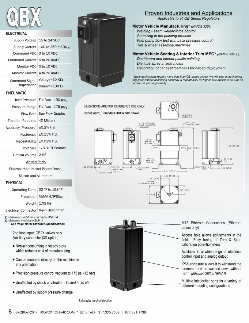
Dual loop technology: This provides us the capability to control virtually any media at any flow rate and any pressure without sacrificing accuracy and repeatability. It also allows us to take feedback from more than just a pressure transducer. With a properly configured dual loop unit we can take feedback from a vacuum transducer, force transducer, torque, flow or position transducer. PID loops no longer need tuned in your controller. Proportion-Air’s dual loop technology makes proportional control easy. It is already done within the unique Proportion-Air analog circuit. You may need to ramp pressure (or vacuum, or force, or torque, or flow, or position) up and down – the QB2 will track the ramped signal from the PLC or computer and achieve the control setting required.
Accuracy: The downstream pressure transducer senses pressure on the work port of the pressure regulator and allows the QB2 to compensate for inaccuracy brought about by the mechanical properties of the regulator.
Repeatability: High flow capability, hydraulic or pneumatic media capability, more simple-to-use control and extremely repeatable: the same conditions with the same command signal from the same direction can have repeatability as high as 0.02% of full scale calibration.
High flow: Pressure reducing or back pressure regulators are available as large as 6 inch flange mount.
Data Acquisition: Just like other Proportion-Air electronic pressure regulators, the QB2 has an analog output that comes from the controlling transducer. This signal in a dual loop device comes from the downstream transducer.
• QB2T with R000C
QB2T with Liquid Backpressure Regulator •
• QB2T with PSR-B QB2X with R000C •
QB2T with Ratio Regulator •

Proportion-Air products are warranted to the original purchaser only against defects in material or workmanship for one (1) year from the date of manufacture. The extent of Proportion-Air's liability under this warranty is limited to repair or replacement of the defective unit at Proportion-Air's option. Proportion-Air shall have no
liability under this warranty where improper installation or filtration occurred.
All specifications are subject to change without notice. THIS WARRANTY IS GIVEN IN LIEU OF, AND BUYER HEREBY EXPRESSLY WAIVES, WARRANTIES OR LIABILITIES, EXPRESS, IMPLIED OR STATUTORY, INCLUDING WITHOUT LIMITATION ANY OBLIGATION OF PROPORTION-AIR WITH REGARD TO
CONSEQUENTIAL DAMAGES, WARRANTIES OF MERCHANTABILITY, DESCRIPTION, AND FITNESS FOR A PARTICULAR PURPOSE. .....................................................................................................................................................................................................................................................................
WARNING: Installation and use of this product should be under the supervision and control of properly qualified personnel in order to avoid the risk of injury or death.
Give us a call or visit us on the web
ProportionAir.com
O N E P R O D U C T T H O U S A N D S O F W A Y S
Proportion-Air, Inc. 8250 N. 600 West, P.O. Box 218 McCordsville, Indiana USA 46055
Phone: 317-335-2602 Fax: 317-335-3853 [email protected]
ProportionAir.com | 877.331.1738
Handcrafted in the USA ISO 9001-2015 Certified
DIMENSIONS ARE FOR REFERENCE USE ONLY
ACCESSORIES
QBT-01
Inches
Inches (mm) Inches (mm)
QBT-02
QBT Power Cord Pre-Assembled Power Cord
Part Number: QBT-C-6 (typical)
LENGTH IN FEET Other lengths are available
(from 1 to 25 feet (8 meters), 1 foot increments)
Option BR, Installed
QBTS-02 (QBS)
Recommended