Fundamentals of Egress Peering Engineering
Application Note
August 2017
Fundamentals of Egress Peering Engineering
2 © 2017 Juniper Networks, Inc.
Juniper Networks, Inc. 1133 Innovation Way Sunnyvale, California 94089 USA 408-745-2000 www.juniper.net
Copyright © 2017, Juniper Networks, Inc. All rights reserved.
Fundamentals of Egress Peering Engineering
© 2017 Juniper Networks, Inc. 3
Table of Contents Defining Egress Peering Engineering ...................................................................................................................................... 4
Cost of peering ...................................................................................................................................................................................... 5 Latency .................................................................................................................................................................................................. 5 Losses .................................................................................................................................................................................................... 5 Exit Link Selection .................................................................................................................................................................................. 5 The Traditional Approach and Its Limitations........................................................................................................................................ 6
A Better Way to Determine Egress ......................................................................................................................................... 8 Data collection ....................................................................................................................................................................................... 9 EPE logic: the EPE controller .................................................................................................................................................................. 9 Intra-AS Traffic Engineering: Another Problem ................................................................................................................................... 10
Principles of EPE .................................................................................................................................................................... 14 Implementation of the EPE Cookie with IP Tunneling ......................................................................................................................... 14 Overview of Solutions with MPLS ........................................................................................................................................................ 17 The Four Solution Architectures .......................................................................................................................................................... 21
Architecture Using an MPLS EPE Cookie for NNI Selection Only .......................................................................................... 22 Intra-AS Routing and LSP Signaling. ..................................................................................................................................................... 22 BGP Infrastructure ............................................................................................................................................................................... 23 External Prefix Advertisement ............................................................................................................................................................. 24 EPE Cookie Label Advertisement ......................................................................................................................................................... 25 The EPE Controller ............................................................................................................................................................................... 26 Ingress ASBR Path Selection and Forwarding State Creation .............................................................................................................. 29 Node Requirements for the Solution .................................................................................................................................................. 31 Redundancy, Convergence and Fast Restoration ................................................................................................................................ 32
Architecture Using EPE with Traditional Intra-AS Traffic Engineering .................................................................................. 34 Intra-AS Routing and LSP Signaling ...................................................................................................................................................... 34 BGP Infrastructure ............................................................................................................................................................................... 37 External Prefix Advertisement ............................................................................................................................................................. 38 EPE Cookie Label Advertisement ......................................................................................................................................................... 39 The EPE Controller ............................................................................................................................................................................... 40 Ingress ASBR Path Selection and Forwarding State Creation .............................................................................................................. 44 Node Requirements for the Solution .................................................................................................................................................. 47 Redundancy, Convergence and Fast Restoration ................................................................................................................................ 47
Architecture Using SPRING for Intra-AS LSPs ........................................................................................................................ 49 Intra-AS Routing and LSP Signaling. ..................................................................................................................................................... 49 BGP Infrastructure ............................................................................................................................................................................... 51 External Prefix Advertisement ............................................................................................................................................................. 52 EPE Cookie Label Advertisement ......................................................................................................................................................... 53 The EPE Controller ............................................................................................................................................................................... 54 Ingress ASBR Path Selection and Forwarding State Creation .............................................................................................................. 57 Node Requirements for the Solution .................................................................................................................................................. 60 Redundancy, Convergence and Fast Restoration ................................................................................................................................ 60
Architecture Using an Integrated TE Controller.................................................................................................................... 62 Intra-AS Routing and LSP Signaling and Segment Labels. .................................................................................................................... 63 BGP infrastructure ............................................................................................................................................................................... 64 External Prefix Advertisement ............................................................................................................................................................. 65 EPE Cookie Label Advertisement ......................................................................................................................................................... 66 SPRING Labels and Topology Learning ................................................................................................................................................ 68 The TE controller ................................................................................................................................................................................. 68 Ingress ASBR Path Selection and Forwarding State Creation .............................................................................................................. 72 Node Requirements for the Solution .................................................................................................................................................. 75 Redundancy, convergence and fast restoration .................................................................................................................................. 75
Fundamentals of Egress Peering Engineering
4 © 2017 Juniper Networks, Inc.
Defining Egress Peering Engineering The Internet – a public global network of networks – is built as system of interconnected networks of Service
Provider (SP) infrastructures. These networks are often represented as Autonomous Systems (ASs) each has globally unique Autonomous System Number (ASN). The data-plane interconnection link (NNI) and control-plane (eBGP) direct connection between two ASs allows Internet traffic to travel between the two, usually as part of a formal agreement called peering.
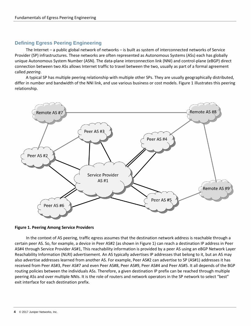
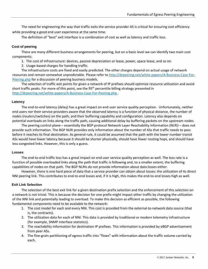
A typical SP has multiple peering relationship with multiple other SPs. They are usually geographically distributed, differ in number and bandwidth of the NNI link, and use various business or cost models. Figure 1 illustrates this peering relationship.
Figure 1. Peering Among Service Providers
In the context of AS peering, traffic egress assumes that the destination network address is reachable through a certain peer AS. So, for example, a device in Peer AS#2 (as shown in Figure 1) can reach a destination IP address in Peer AS#4 through Service Provider AS#1, This reachability information is provided by a peer AS using an eBGP Network Layer Reachability Information (NLRI) advertisement. An AS typically advertises IP addresses that belong to it, but an AS may also advertise addresses learned from another AS. For example, Peer AS#2 can advertise to SP (AS#1) addresses it has received from Peer AS#3, Peer AS#7 and even Peer AS#8, Peer AS#9, Peer AS#4 and Peer AS#5. It all depends of the BGP routing policies between the individuals ASs. Therefore, a given destination IP prefix can be reached through multiple peering ASs and over multiple NNIs. It is the role of routers and network operators in the SP network to select “best” exit interface for each destination prefix.
Fundamentals of Egress Peering Engineering
© 2017 Juniper Networks, Inc. 5
The need for engineering the way that traffic exits the service provider AS is critical for ensuring cost efficiency while providing a good end user experience at the same time.
The definition of “best” exit interface is a combination of cost as well as latency and traffic loss.
Cost of peering There are many different business arrangements for peering, but on a basic level we can identify two main cost
components: 1. The cost of infrastructure: devices, passive depreciation or lease, power, space lease, and so on. 2. Usage-based charges for handling traffic. The infrastructure costs are fixed and easily predicted. The other charges depend on actual usage of network
resources and remain somewhat unpredictable. Please refer to http://drpeering.net/white-papers/A-Business-Case-For-Peering.php for a discussion of peering business models.
The selection of traffic exit points for given a network of IP prefixes should optimize resource utilization and avoid short traffic peaks. For more of this point, see the 95th percentile billing strategy presented in http://drpeering.net/white-papers/A-Business-Case-For-Peering.php .
Latency The end-to-end latency (delay) has a great impact on end user service quality perception. Unfortunately, neither
end users nor their service providers aware that the observed latency is a function of physical distance, the number of nodes (routers/switches) on the path, and their buffering capability and configuration. Latency also depends on potential overloads on links along the traffic path, causing additional delay by buffering packets on the upstream nodes.
The peering control plane – essentially the BGP protocol Network Layer Reachability Information (NLRI) – does not provide such information. The BGP NLRI provides only information about the number of ASs that traffic needs to pass before it reaches its final destination. As general rule, it could be assumed that the path with the lower number transit ASs would have lower latency because it should be shorter physically, should have fewer routing hops, and should have less congested links. However, this is only a guess.
Losses The end-to-end traffic loss has a great impact on end user service quality perception as well. The loss rate is a
function of possible overloaded links along the path that traffic is following and, to a smaller extent, the buffering capabilities of nodes on that path. The BGP NLRIs do not provide information about data losses either.
However, there is one hard piece of data that a service provider can obtain about losses: the utilization of its direct NNI peering link. This contributes to end-to-end losses and, if it is high, this makes the end-to-end losses high as well.
Exit Link Selection The selection of the best exit link for a given destination prefix selection and the enforcement of this selection on
a network is not trivial. This is because the decision for one prefix might impact other traffic by changing the utilization of the NNI link and potentially leading to overload. To make this decision as efficient as possible, the following fundamental components need to be available to the network:
1. The cost model for each and every NNI. This cost is provided from the external-to-network data source (that is, the contracts).
2. The utilization data for each of NNI. This data is provided by traditional or modern telemetry infrastructure (for example, SNMP interface statistics).
3. The reachability information for destination IP prefixes. This information is provided by eBGP advertisement from peer ASs.
4. The fine-grain partitioning of egress traffic into “flows” with information about the traffic volume carried by each.
Fundamentals of Egress Peering Engineering
6 © 2017 Juniper Networks, Inc.
5. An Egress Peering Engineering (EPE) controller that executes some logic to map the above “flows” to NNI in a globally optimal way.
6. A network infrastructure that allows forwarding traffic from an ingress AS Border Router (ASBR) on a customer service provider network to the designated egress NNI, as determined by the EPE controller.
This document focuses on describing components (3), (4) and (6) and provides some information about the EPE
controller (5) when necessary.
The Traditional Approach and Its Limitations Traditionally, SPs use a policy to manipulate the BGP attributes contained in NLRIs received from a peer. This
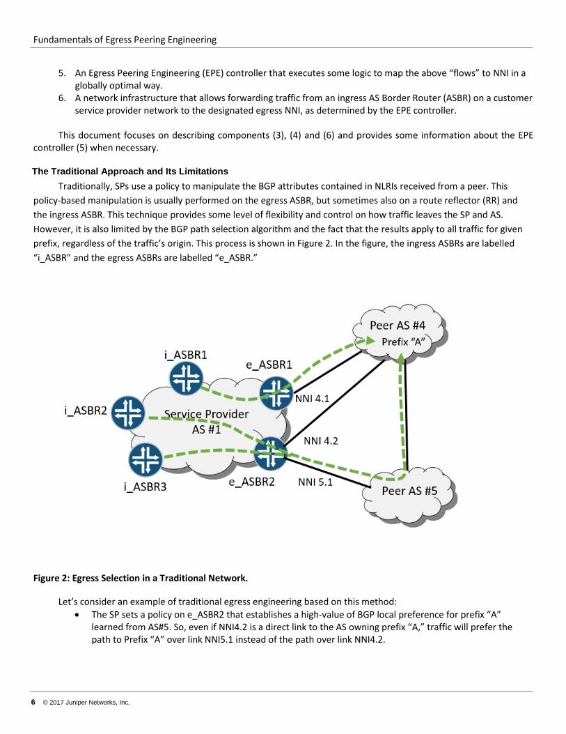
policy-based manipulation is usually performed on the egress ASBR, but sometimes also on a route reflector (RR) and the ingress ASBR. This technique provides some level of flexibility and control on how traffic leaves the SP and AS. However, it is also limited by the BGP path selection algorithm and the fact that the results apply to all traffic for given prefix, regardless of the traffic’s origin. This process is shown in Figure 2. In the figure, the ingress ASBRs are labelled “i_ASBR” and the egress ASBRs are labelled “e_ASBR.”
Figure 2: Egress Selection in a Traditional Network.
Let’s consider an example of traditional egress engineering based on this method: • The SP sets a policy on e_ASBR2 that establishes a high-value of BGP local preference for prefix “A”
learned from AS#5. So, even if NNI4.2 is a direct link to the AS owning prefix “A,” traffic will prefer the path to Prefix “A” over link NNI5.1 instead of the path over link NNI4.2.
Fundamentals of Egress Peering Engineering
© 2017 Juniper Networks, Inc. 7
• As result of this policy, packet with a destination IP address matching prefix “A” is sent by e_ASBR2 out through NNI 5.1, regardless of the packet’s origin (that is, ingress ASBR).
• If AS#1’s iBGP infrastructure advertises from e_ASBRs to each ingress ASBR, the policy (if any) on a particular ingress ASBR may choose e_ASBR1 or e_ASBR2 as the egress point, but not the actual NNI to use. So there is no way for i_ASBR2 to select NNI4.2 as the best exit point for prefix “A” traffic.
Please note that the path used to deliver traffic from i_ASBR to an e_ASBR is unrelated to exit NNI selection. In an MPLS network with Traffic Engineering (TE) enabled, you can select a particular Label Switched Path (LSP), providing there is more than one. The selection is based on a policy and the LSP name. Otherwise, the path to the selected e_ASBR is simply the shortest path determined by the Interior Gateway Protocol (IGP).
In summary, the traditional approach for egress engineering is limited by: • Egress link selection for each destination prefix, as determined on the egress ASBR. • Egress ASBR selection for each destination prefix on the ingress ASBR, but without egress link visibility or
selection.
Fundamentals of Egress Peering Engineering
8 © 2017 Juniper Networks, Inc.
A Better Way to Determine Egress The traditional approach to EPE may result in suboptimal decisions. For example, the interface NNI4.1 could be
unutilized because the routing policy prefers a path through AS#5. One could argue that other prefixes in AS#4 could be routed over NNI4.1, but these other prefixes might carry much less traffic.
If EPE had the ability to distribute traffic among several egress links based not only on destination address, but also by considering the ingress ASBR (or ingress port, or even originating node/host), this would provide much finer granularity and also bandwidth management. This would be especially true if EPE were combined with traffic statistics and centralized optimization.
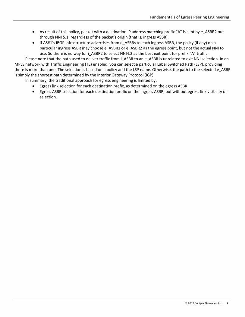
We can express our goal as follows: The EPE solution should direct traffic for a given prefix that enters the network on a particular i_ASBR to a particular egress NNI on a particular e_ASBR.
To describe this relationship, the following notation will be used: [i_ASBR, prefix]NNI
For example, for the SP running AS#1: [i_ASBR1, A ] NN4.1 [i_ASBR2, A ] NN4.2 [i_ASBR3, A ] NN5.1
This method is illustrated in Figure 3.
Figure 3. The Desired Capability of the EPE.
Fundamentals of Egress Peering Engineering
© 2017 Juniper Networks, Inc. 9
The EPE solution consists of the following components: 1. Data collection to allow global optimization of egress routing. 2. EPE logic that builds a table of ingress ASBRs, IP destination prefixes, and egress NNI to use in the form
[i_ASBR, prefix]NNI. This table can cover all prefixes and i_ASBRs pairs or only a subset, leaving the undefined prefixes subjected to traditional routing.
3. Network signaling, control protocols, and data path states that enforce EPE logic decisions. This write-up focus on the last item, while the other two are briefly discussed below in order to provide a more
complete context.
Data collection Egress routing optimization could be based on multiple parameters: NNI link capacity, latency, end-to-end loss
rate, or even cost of transit service (for volume-based or “95th percentile” charged peering). In any case, the data collection needs to be at least as granular as the “flows” to be routed. Therefore, traffic volumes need to be collected for each [i_ASBR, prefix] pair. The same data is needed for latency. The methodology used could be different. Some examples include data from JFlow/NetFlow export from the i_ASBR, SNMP MIB-based per-prefix counters, or sampling mirrored traffic to determine the TCP packet-to-acknowledge round-trip-time.
The actual data collection method and analytics applied are beyond the scope of this document. For the rest of this paper, it is assumed that necessary data are available to the EPE logic operations discussed below.
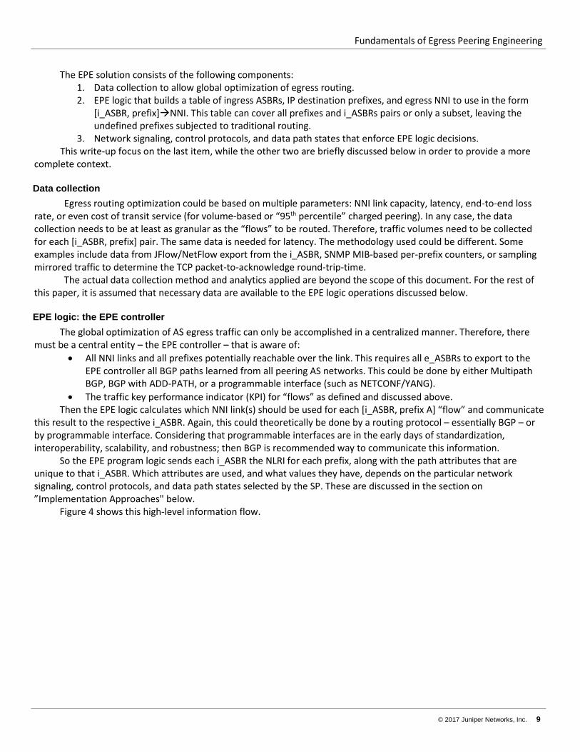
EPE logic: the EPE controller The global optimization of AS egress traffic can only be accomplished in a centralized manner. Therefore, there
must be a central entity – the EPE controller – that is aware of: • All NNI links and all prefixes potentially reachable over the link. This requires all e_ASBRs to export to the
EPE controller all BGP paths learned from all peering AS networks. This could be done by either Multipath BGP, BGP with ADD-PATH, or a programmable interface (such as NETCONF/YANG).
• The traffic key performance indicator (KPI) for “flows” as defined and discussed above. Then the EPE logic calculates which NNI link(s) should be used for each [i_ASBR, prefix A] “flow” and communicate
this result to the respective i_ASBR. Again, this could theoretically be done by a routing protocol – essentially BGP – or by programmable interface. Considering that programmable interfaces are in the early days of standardization, interoperability, scalability, and robustness; then BGP is recommended way to communicate this information.
So the EPE program logic sends each i_ASBR the NLRI for each prefix, along with the path attributes that are unique to that i_ASBR. Which attributes are used, and what values they have, depends on the particular network signaling, control protocols, and data path states selected by the SP. These are discussed in the section on ”Implementation Approaches" below.
Figure 4 shows this high-level information flow.
Fundamentals of Egress Peering Engineering
10 © 2017 Juniper Networks, Inc.
Figure 4. The High-Level Information Flow to and from the EPE.
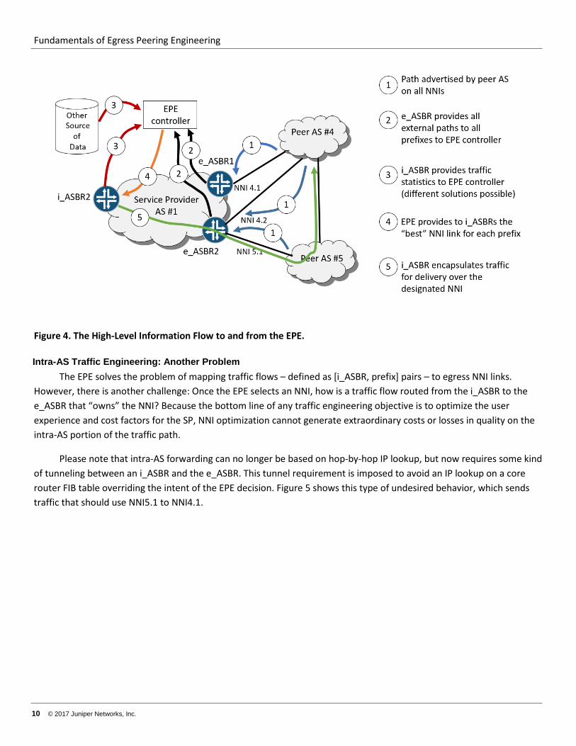
Intra-AS Traffic Engineering: Another Problem The EPE solves the problem of mapping traffic flows – defined as [i_ASBR, prefix] pairs – to egress NNI links.
However, there is another challenge: Once the EPE selects an NNI, how is a traffic flow routed from the i_ASBR to the e_ASBR that “owns” the NNI? Because the bottom line of any traffic engineering objective is to optimize the user experience and cost factors for the SP, NNI optimization cannot generate extraordinary costs or losses in quality on the intra-AS portion of the traffic path.
Please note that intra-AS forwarding can no longer be based on hop-by-hop IP lookup, but now requires some kind of tunneling between an i_ASBR and the e_ASBR. This tunnel requirement is imposed to avoid an IP lookup on a core router FIB table overriding the intent of the EPE decision. Figure 5 shows this type of undesired behavior, which sends traffic that should use NNI5.1 to NNI4.1.
Fundamentals of Egress Peering Engineering
© 2017 Juniper Networks, Inc. 11
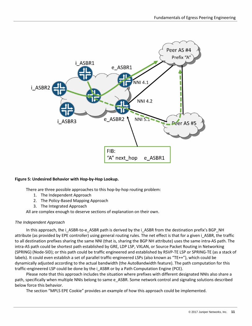
Figure 5: Undesired Behavior with Hop-by-Hop Lookup.
There are three possible approaches to this hop-by-hop routing problem: 1. The Independent Approach 2. The Policy-Based Mapping Approach 3. The Integrated Approach
All are complex enough to deserve sections of explanation on their own.
The Independent Approach
In this approach, the i_ASBR-to-e_ASBR path is derived by the i_ASBR from the destination prefix’s BGP_NH attribute (as provided by EPE controller) using general routing rules. The net effect is that for a given i_ASBR, the traffic to all destination prefixes sharing the same NNI (that is, sharing the BGP NH attribute) uses the same intra-AS path. The intra-AS path could be shortest path established by GRE, LDP LSP, VXLAN, or Source Packet Routing in Networking (SPRING) (Node-SID); or this path could be traffic engineered and established by RSVP-TE LSP or SPRING-TE (as a stack of labels). It could even establish a set of parallel traffic-engineered LSPs (also known as “TE++”), which could be dynamically adjusted according to the actual bandwidth (the AutoBandwidth feature). The path computation for this traffic-engineered LSP could be done by the i_ASBR or by a Path Computation Engine (PCE).
Please note that this approach includes the situation where prefixes with different designated NNIs also share a path, specifically when multiple NNIs belong to same e_ASBR. Some network control and signaling solutions described below force this behavior.
The section “MPLS EPE Cookie” provides an example of how this approach could be implemented.
Fundamentals of Egress Peering Engineering
12 © 2017 Juniper Networks, Inc.
The Policy-Based Mapping Approach
In this approach, if the intra-AS path requires some traffic engineering (that is, traffic does not follow the IGP shortest path), then the SP may decide to provision multiple LSPs for the same Forwarding Equivalent Class (FEC) from each i_ASBR. Each LSP has slightly different characteristics, and the LSP name reflects this characteristic in a non-ambiguous format. For example, one path could be Fast Re-Route (FRR) protected, another follows a low-latency path, and another has a bandwidth guarantee or follows the lowest monetary cost path. All of these LSPs establish equally good paths toward the NNI. The EPE controller, when providing the i_ASBR with a destination prefix NNI, also attaches a “cookie” that helps the i_ASBR select the desired intra-AS path. If the EPE controller uses BGP to communicate this information (as is likely), then this “cookie” is a BGP community string.
Please note that the i_ASBR-to-e_ASBR path is still derived by the i_ASBR from the destination prefix’s BGP Next Hop attribute, as provided by the EPE controller. The i_ASBR uses general routing rules, but with an additional policy. The net effect is that for a given i_ASBR, traffic to particular destination prefixes sharing the same NNI (that is, the BGP Next Hop attribute) selects one LSP while traffic to other destination prefixes is mapped to other LSPs. Also note that this does not preclude the situation where prefixes with different designated NNIs share an LSP path, especially when the NNIs belong to same e_ASBR. Some network control and signaling solutions described below forces this behavior. Finally, note that the policy-based mapping approach addresses a broader issue than egress peering traffic. This is because, for a given prefix entering the network on a particular i_ASBR, this method allows the direction of the traffic to particular egress NNI over an intra-AS path that matches certain criteria, but without specifying this path explicitly.
To describe the above relation, the following notation could be used: [i_ASBR, prefix][inta-AS-path, NNI]. For example, for the SP of AS#1:
[i_ASBR1, A ] [“AutoBW”, NN4.1]
[i_ASBR1, B ] [“low-latency”, NN4.1]
[i_ASBR3, A ] [“best-effort”, NN5.1]
The section “EPE with Traditional Intra-AS Traffic Engineering” provides an example of how this approach could be implemented. The Integrated Approach
In this approach, the intra-AS path is calculated independently for each EPE flow (that is, [i_ASBR, prefix]) by the central EPE controller (or confederation of controllers). Then the i_ASBR is provided not only with an egress NNI, but also with the exact intra-AS path. Obviously, this scenario gives the best granularity and allows for the highest degree of optimization. However, it is also the hardest to manage and troubleshoot, especially as it scales. It also results in a potential “state explosion,” at least in the controller complex, but potentially also in the network if RSVP is used as the LSP signaling protocol.
Please note that the integrated approach addresses broader issues then egress peering traffic. This is because, for a given prefix entering the network on a particular i_ASBR, this method allows the direction of traffic for a given prefix to a particular egress NNI over a unique and specific intra-AS path.
To describe the above relation, the following notation could be used: [i_ASBR, prefix][inta-AS-path, NNI]. For example, for the SP of AS#1, where “ifl” is a network-wide identifier (IP address or other notation) of an interface:
[i_ASBR1, A ] [“ifl1, ifl4, ifl13, ifl27, e_ASBR1”, NN4.1] [i_ASBR1, B ] [“ifl100, ifl203, e_ASBR1”, NN4.1]
Fundamentals of Egress Peering Engineering
© 2017 Juniper Networks, Inc. 13
[i_ASBR3, A ] [“ifl100, ifl203, e_ASBR1”, NN5.1] The final two sections on EPE solution architectures provide examples that implement this approach. In conclusion, it should be noted that all three approaches are valid and address slightly different issues. It is the
SP’s decision to make, based on real issues from experience, the willingness to invest in controller infrastructure, the risk tolerance for new technologies, and the SP’s ability to operate, maintain, and troubleshoot a controller-driven network.
Fundamentals of Egress Peering Engineering
14 © 2017 Juniper Networks, Inc.
Principles of EPE When it comes to implementing an EPE on a network, the first need is classification of packets into a flow
(definitions are flexible, but must be consistent). The easiest place to do this is at the ingress ASBR, as a destination lookup is required there anyway. The i_ASBR could determine the correct e_ASBR for traffic egress if the EPE controller provided the i_ASBR with routing information that maps each destination prefix to an NNI, or, more specifically, the IP address of the interface. Assuming tunneling inside the AS (see the section on Intra-AS Traffic Engineering), the packet is delivered directly to the e_ASBR.
Considering “plain” IP packets, the e_ASBR needs to classify arriving packets into the correct EPE flow in order to identify the proper NNI or peer IP address. This process is not trivial, and might be impossible. Reverse lookups to find a source do not necessary return the i_ASBR that a packet actually used to enter the network. Also, this is an expensive process.
Therefore, the e_ASBR needs to have a “hint” from each i_ASBR to help the e_ASBR identify the correct EPE flow. This hint needs to be carried along with the packet, encoded in some packet header field or as an additional header. Using the IP packet header is problematic: in theory, IPv4 options or IPv6 sub-headers (source-routing) or the IPv6 flow-label could be used, but network devices such as routers are not optimized to process that information. Therefore, the only available option is to add some additional encapsulation and header onto the IP packet. For the purposes of this document, this additional header is called the “EPE cookie header.” Later in this document, when different EPE architectures are discussed, the actual implementation of this EPE cookie header is discussed.
It is worth noting, as this point, the possible semantics of the EPE cookie header: • Only the identification of the ingress ASBR is included. In this case, the e_ASBR would need to perform a
destination lookup in the context representing the i_ASBR. • Identification of the NNI link the e_ASBR should use for the traffic flow. In this case, depending on
implementation specifics, the destination IP lookup could be avoided or simplified.
Encoding the NNI directly into EPE cookie header is possible because it is done on i_ASBR, but this requires a communication channel between the ingress and egress ASBRs in order to agree on cookie values.
Implementation of the EPE Cookie with IP Tunneling The implications of the precise form and content of the EPE cookie header using some form of IP tunneling are
explored below.
The EPE Cookie as an i_ASBR Indicator
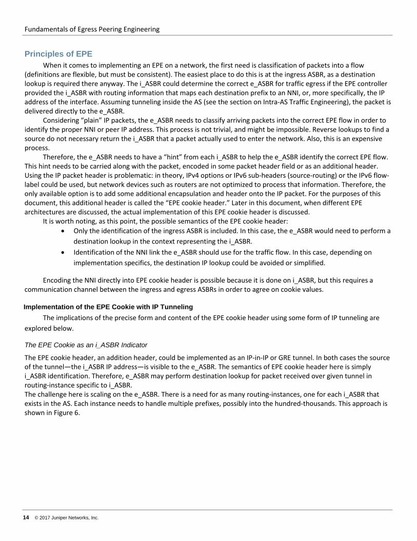
The EPE cookie header, an addition header, could be implemented as an IP-in-IP or GRE tunnel. In both cases the source of the tunnel—the i_ASBR IP address—is visible to the e_ASBR. The semantics of EPE cookie header here is simply i_ASBR identification. Therefore, e_ASBR may perform destination lookup for packet received over given tunnel in routing-instance specific to i_ASBR. The challenge here is scaling on the e_ASBR. There is a need for as many routing-instances, one for each i_ASBR that exists in the AS. Each instance needs to handle multiple prefixes, possibly into the hundred-thousands. This approach is shown in Figure 6.
Fundamentals of Egress Peering Engineering
© 2017 Juniper Networks, Inc. 15
Figure 6. Tunneling EPE cookie headers from i_ASBR to e-ASBR.
Note that the intra-AS tunnel discussed in the Intra-AS Traffic Engineering: Another Approach section is re-used and fulfils two roles: the i_ASBR to e_ASBR tunnel over the core network, as well as the carrier of this EPE cookie header. As IP-based GRE tunnels follow the “best” IGP routes, traffic engineering of this intra-AS path is not possible.
Use of the GRE Key for the EPE Cookie
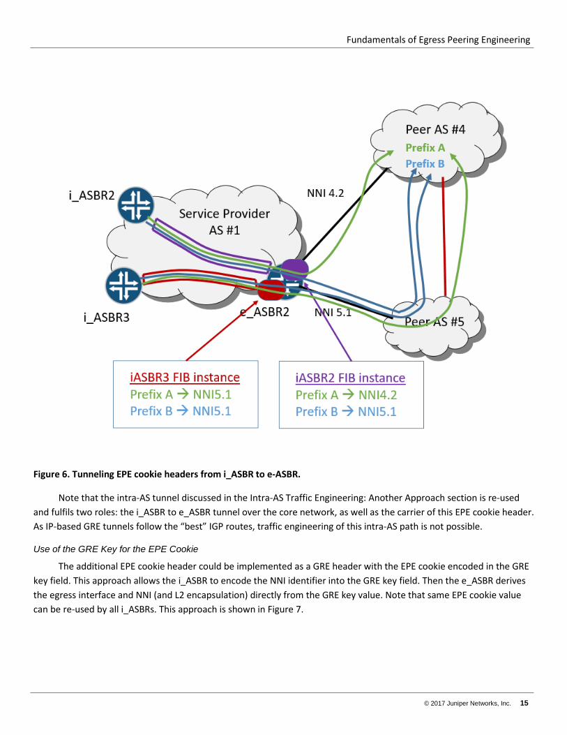
The additional EPE cookie header could be implemented as a GRE header with the EPE cookie encoded in the GRE key field. This approach allows the i_ASBR to encode the NNI identifier into the GRE key field. Then the e_ASBR derives the egress interface and NNI (and L2 encapsulation) directly from the GRE key value. Note that same EPE cookie value can be re-used by all i_ASBRs. This approach is shown in Figure 7.
Fundamentals of Egress Peering Engineering
16 © 2017 Juniper Networks, Inc.
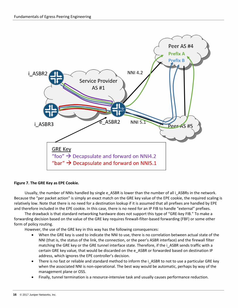
Figure 7. The GRE Key as EPE Cookie.
Usually, the number of NNIs handled by single e_ASBR is lower than the number of all i_ASBRs in the network. Because the “per packet action” is simply an exact match on the GRE key value of the EPE cookie, the required scaling is relatively low. Note that there is no need for a destination lookup if it is assumed that all prefixes are handled by EPE and therefore included in the EPE cookie. In this case, there is no need for an IP FIB to handle “external” prefixes.
The drawback is that standard networking hardware does not support this type of “GRE-key FIB.” To make a forwarding decision based on the value of the GRE key requires firewall-filter-based forwarding (FBF) or some other form of policy routing.
However, the use of the GRE key in this way has the following consequences: • When the GRE key is used to indicate the NNI to use, there is no correlation between actual state of the
NNI (that is, the status of the link, the connection, or the peer’s ASBR interface) and the firewall filter matching the GRE key or the GRE tunnel interface state. Therefore, if the i_ASBR sends traffic with a certain GRE key value, that would be discarded on the e_ASBR or forwarded based on destination IP address, which ignores the EPE controller’s decision.
• There is no fast or reliable and standard method to inform the i_ASBR to not to use a particular GRE key when the associated NNI is non-operational. The best way would be automatic, perhaps by way of the management plane or OSS.
• Finally, tunnel termination is a resource-intensive task and usually causes performance reduction.
Fundamentals of Egress Peering Engineering
© 2017 Juniper Networks, Inc. 17
So the solutions based on IP tunnels all share the same limitations: they require configuration of an EPE cookie value manually. Also, the management of the naming space, which ensures that the value used is unique and properly interpreted, is fully dependent on some form of off-network provisioning system.
Overview of Solutions with MPLS MPLS is a tunneling technique that assigns a “cookie” label to leverage the FIB and perform packet processing. In
the MPLS solution, an e_ASBR allocates a label for each of its direct external peers and advertises this binding to all i_ASBRs. The MPLS FIB of the e_ASBR is programmed with a pop-and-forward action: the egress interface and L2 encapsulation is derived from the label value according to FIB content.
When an e_ASBR receives a packet with that MPLS label, it performs MPLS forwarding. The binding of the label to a particular NNI (more precisely, the IP address of a peer ASBR’s interface) is local logic to the e_ASBR. The only requirements are:
• The label needs to be unique in the context of the e_ASBR and may not be a null label. • The label operation needs to be a pop and forward. The direct next-hop and L2 encapsulation needs to
reflect the family (IPv4 or IPv6) of the peer’s interface address, and the L2 destination address (MAC address) needs to be the address of the peer’s ASBR interface.
This label binding needs to be advertised and learned by the EPE Controller, all i_ASBRs, or both, depending on the particular design and requirement of the network. This label distribution could be done using:
• BGP-LU (RFC3107) or • BGP-LS (as specified by draft-filsfils-spring-segment-routing-central-epe-05), which is developed in the IETF
SPRING working group. • LDP • API access to a router’s management plane from an OSS/BSS (an SDN controller) • Through static label provisioning
Let’s look at them in detail, but it in the reverse order, for reasons that will be obvious when we get to BGP-LU (RFC3107).
The last option—static label provisioning—has the same shortcomings as a GRE-based solution. That is, the need for manual allocation and maintenance of “EPE cookie” label values and the lack of signaling for the state of the NNI. This could lead to a backhaul situation when an i_ASBR (or even a server in a data center environment) pushes a statically provisioned label onto a packet, but the NNI associated with it is down. The small advantage of this solution over GRE is the use of the e_ASBR’s FIB for traffic steering instead of a firewall filter. Considering the limitations of this method, it is not discussed further here.
That said, static label allocation could be an interesting option for rapid deployment of an EPE in a data center, until a more dynamic way of providing an EPE cookie label to a server is developed. For example, this label value could be learned from BGP and a provision server’s routing table entries using RPC or API calls from an EPE controller.
As for API access, using SDN or other management plane is a very broad category that needs further specification, right down to the protocols and procedures used to propagate label binding to an NNI. This API and models are not standardized now, so any solution would be very vendor-specific and tailor made. Therefore, this method is not attractive, especially in the case where better, standard mechanisms exists.
Moving up the list, the use of LDP for the propagation of label binding to NNI information requires inclusion of the peer ASBR interface address as an IGP host route. Although it is generally possible (this method is not supported by the Junos OS), it exposes the potential instability of the NNI link to the IGP and, consequently, to each and every router in network, even the core nodes. Additionally, this approach requires creation of a static host route on an e_ASBR with the same address as the next-hop. Such configuration is not widely supported within the industry and some routers flag this as a misconfiguration. Please note that such a static route might be active, and thus propagated into the IGP, even if the peer ASBR (or it’s related interface) is unreachable or in a fault state.
Fundamentals of Egress Peering Engineering
18 © 2017 Juniper Networks, Inc.
Use of BGP-LS is a promising technology, because it allows for the inclusion of additional information about the NNI, such affinity groups, bandwidth reservations, and so on. At the same time, this technology is in the development stage and IETF consensus is that it is not yet finished. There are very few, if any, routers that support BGP-LS. So the use of BGP-LS for carrying the label EPE cookie is simply premature.
Finally, consider BGP-LU. This protocol is mature, scalable, stable, and allows for the control of the recipients of label-to-NNI-binding information. So this is a simple way to keep core routers NNI-unaware (also to NNI state changes) or limit label-to-NNI distribution to an EPE Controller only, or only to some group of i_ASBRs, depending on network design and requirements. Moreover, thanks to BGP’s heritage, BGP-LU can carry some NNI characteristics through (for example) community attributes. In the discussion below, BGP-LU is used to illustrate a few examples of EPE solutions using high-level designs.
Label-to-NNI Bindings and Propagation Using BGP-LU in the Junos OS
Label allocation and NNI binding, as stated above, is subject to the router’s local procedures and software. In the Junos OS, the egress-te knob under eBGP neighbor configuration triggers special functionality.
When the egress-te knob is enabled, an e_ASBR creates a host route for the address of the external neighbor, and inserts this address into the inet.3 RIB as a route learned from ARP (although it is not really learned this way). When iBGP-LU is configured to a RR, an i_ASBR, or EPE Controller, the Junos OS:
• Allocates a label for this IP address, • Advertises this IP address and bonded label value in a labeled-unicast NLRI in BGP-LU, • Creates an MPLS forwarding state for the allocated label in the MPLS FIB (mpls.0), with the following
associated actions: o POP the label, o Use the L2 encapsulation inherited from the IP “ARP” of inet.3 – that is, the peer’s ASBR interface, o Use the egress interface inherited from IP “ARP” of inet.3 – that is, the peer ASBR link (NNI).
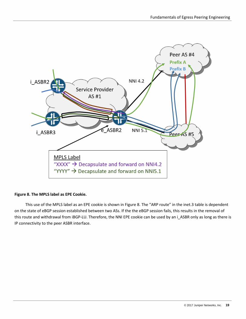
Figure 8 shows an example of the MPLS label as an EPE cookie.
Fundamentals of Egress Peering Engineering
© 2017 Juniper Networks, Inc. 19
Figure 8. The MPLS label as EPE Cookie.
This use of the MPLS label as an EPE cookie is shown in Figure 8. The “ARP route” in the inet.3 table is dependent on the state of eBGP session established between two ASs. If the the eBGP session fails, this results in the removal of this route and withdrawal from iBGP-LU. Therefore, the NNI EPE cookie can be used by an i_ASBR only as long as there is IP connectivity to the peer ASBR interface.
Fundamentals of Egress Peering Engineering
20 © 2017 Juniper Networks, Inc.
Intra-AS Tunnels for an MPLS-based EPE cookie
For networks using MPLS to encode the EPE cookie and BGP-LU as propagation mechanism, the use of other intra-AS LSP tunnels seems to be a logical and common-sense approach. For this, any MPLS intra-AS protocol could be used: LDP, RSVP, SPRING, or even another BGP-LU prefix (for an S-MPLS architecture).
NOTE: Keep in mind that there are situations when an i_ASBR may not be a full-blown carrier-class router. The i_ASBR could be (for example) a routing agent on a data center server’s kernel or hypervisor. In such cases, use of RSVP and LDP is problematic because this use would require the server to run an IGP as well. So we would have a stew of at least three protocols (an IGP, BGP, and LDP or RSVP). There is also a related scaling problem: there would be hundreds of servers participating in the IGP. Please note that all of the above MPLS protocols allocate labels dynamically on per-hop basis, and so, without participation, the servers would not know what label to use in order to reach particular e_ASBR.
For this use case, the solution could be a GRE tunnel that carries a label to use as the EPE cookie for an e_ASBR. Another option could be SPRING, under the assumption that the base label of the SRGB is same on all nodes. Then the needed intra-AS label could be easily derived algorithmically using the e_ASBR Node-SID. Please note that both the tunnel target address (typically, an e_ASBR’s loopback address) and the EPE cookie label could be given to the server by way of a provisioning channel rather than through a routing protocol.
Fundamentals of Egress Peering Engineering
© 2017 Juniper Networks, Inc. 21
The Four Solution Architectures The following sections detail, at a high level, the architectures of four distinct implementations using MPLS labels as the EPER cookie:
1. EPE for NNI selection only 2. EPE with traditional intra-AS traffic engineering 3. EPE with SPRING for intra-AS LSPs 4. Integrated TE Controller
It should be noted that each of the sections has a similar overall structure. For example, sections on intra-AS routing are followed by sections on the BGP infrastructure and end with failure scenarios. However, similar sections can have different content, especially in implementation details.
Fundamentals of Egress Peering Engineering
22 © 2017 Juniper Networks, Inc.
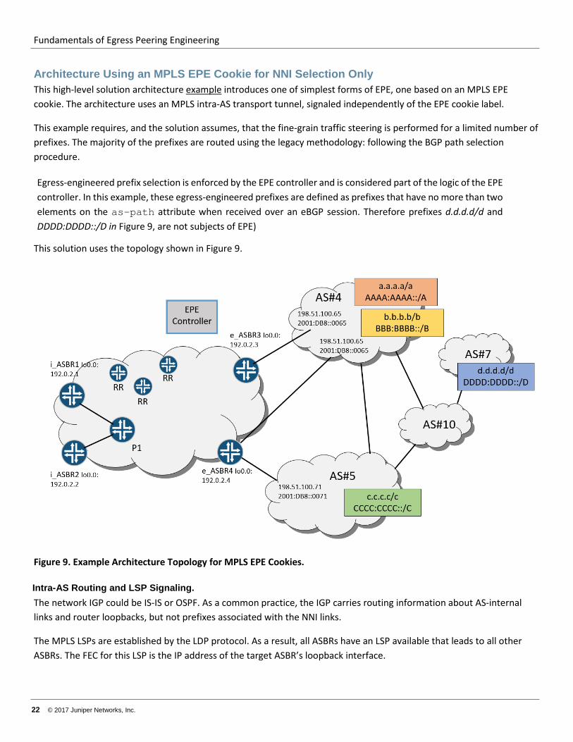
Architecture Using an MPLS EPE Cookie for NNI Selection Only This high-level solution architecture example introduces one of simplest forms of EPE, one based on an MPLS EPE cookie. The architecture uses an MPLS intra-AS transport tunnel, signaled independently of the EPE cookie label.
This example requires, and the solution assumes, that the fine-grain traffic steering is performed for a limited number of prefixes. The majority of the prefixes are routed using the legacy methodology: following the BGP path selection procedure.
Egress-engineered prefix selection is enforced by the EPE controller and is considered part of the logic of the EPE controller. In this example, these egress-engineered prefixes are defined as prefixes that have no more than two elements on the as-path attribute when received over an eBGP session. Therefore prefixes d.d.d.d/d and DDDD:DDDD::/D in Figure 9, are not subjects of EPE)
This solution uses the topology shown in Figure 9.
Figure 9. Example Architecture Topology for MPLS EPE Cookies.
Intra-AS Routing and LSP Signaling. The network IGP could be IS-IS or OSPF. As a common practice, the IGP carries routing information about AS-internal links and router loopbacks, but not prefixes associated with the NNI links.
The MPLS LSPs are established by the LDP protocol. As a result, all ASBRs have an LSP available that leads to all other ASBRs. The FEC for this LSP is the IP address of the target ASBR’s loopback interface.
Fundamentals of Egress Peering Engineering
© 2017 Juniper Networks, Inc. 23
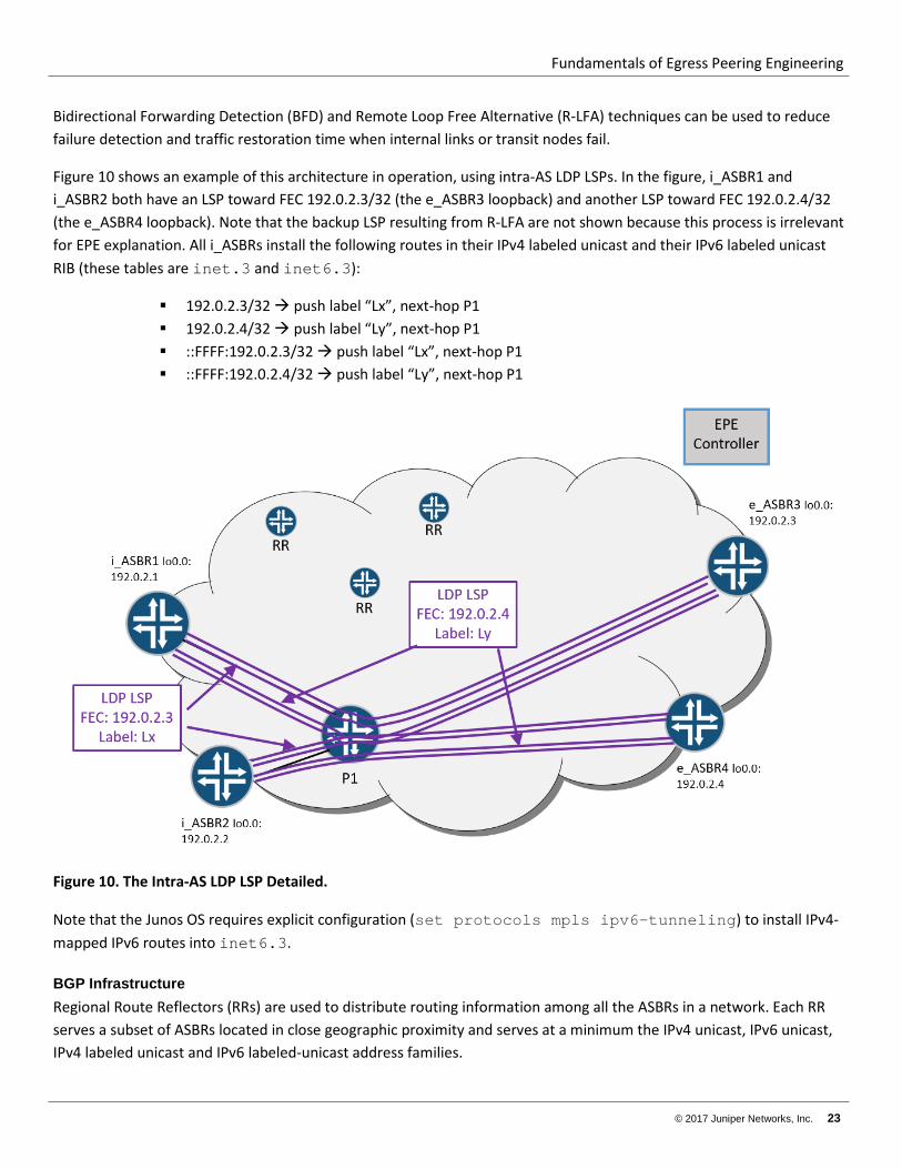
Bidirectional Forwarding Detection (BFD) and Remote Loop Free Alternative (R-LFA) techniques can be used to reduce failure detection and traffic restoration time when internal links or transit nodes fail.
Figure 10 shows an example of this architecture in operation, using intra-AS LDP LSPs. In the figure, i_ASBR1 and i_ASBR2 both have an LSP toward FEC 192.0.2.3/32 (the e_ASBR3 loopback) and another LSP toward FEC 192.0.2.4/32 (the e_ASBR4 loopback). Note that the backup LSP resulting from R-LFA are not shown because this process is irrelevant for EPE explanation. All i_ASBRs install the following routes in their IPv4 labeled unicast and their IPv6 labeled unicast RIB (these tables are inet.3 and inet6.3):
192.0.2.3/32 push label “Lx”, next-hop P1 192.0.2.4/32 push label “Ly”, next-hop P1 ::FFFF:192.0.2.3/32 push label “Lx”, next-hop P1 ::FFFF:192.0.2.4/32 push label “Ly”, next-hop P1
Figure 10. The Intra-AS LDP LSP Detailed.
Note that the Junos OS requires explicit configuration (set protocols mpls ipv6-tunneling) to install IPv4-mapped IPv6 routes into inet6.3.
BGP Infrastructure Regional Route Reflectors (RRs) are used to distribute routing information among all the ASBRs in a network. Each RR serves a subset of ASBRs located in close geographic proximity and serves at a minimum the IPv4 unicast, IPv6 unicast, IPv4 labeled unicast and IPv6 labeled-unicast address families.
Fundamentals of Egress Peering Engineering
24 © 2017 Juniper Networks, Inc.
All RRs are fully meshed by iBGP sessions in order to ensure propagation of routing information across all ASBRs. This RR infrastructure is common in SP networks.
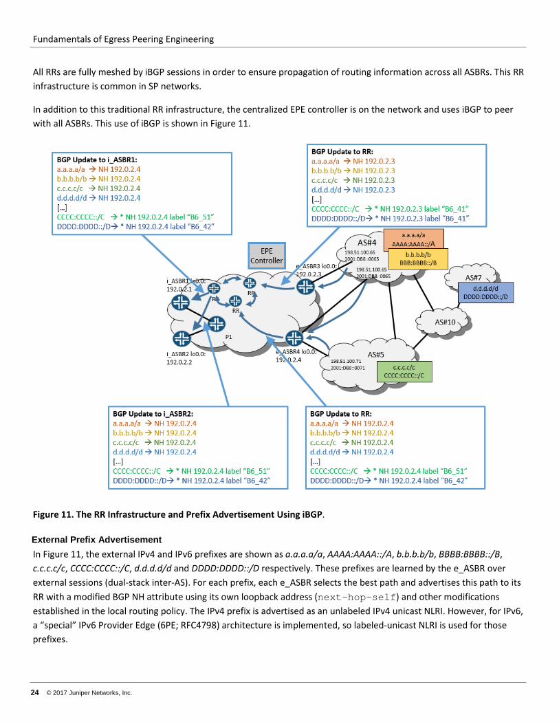
In addition to this traditional RR infrastructure, the centralized EPE controller is on the network and uses iBGP to peer with all ASBRs. This use of iBGP is shown in Figure 11.
Figure 11. The RR Infrastructure and Prefix Advertisement Using iBGP.
External Prefix Advertisement In Figure 11, the external IPv4 and IPv6 prefixes are shown as a.a.a.a/a, AAAA:AAAA::/A, b.b.b.b/b, BBBB:BBBB::/B, c.c.c.c/c, CCCC:CCCC::/C, d.d.d.d/d and DDDD:DDDD::/D respectively. These prefixes are learned by the e_ASBR over external sessions (dual-stack inter-AS). For each prefix, each e_ASBR selects the best path and advertises this path to its RR with a modified BGP NH attribute using its own loopback address (next-hop-self) and other modifications established in the local routing policy. The IPv4 prefix is advertised as an unlabeled IPv4 unicast NLRI. However, for IPv6, a “special” IPv6 Provider Edge (6PE; RFC4798) architecture is implemented, so labeled-unicast NLRI is used for those prefixes.
Fundamentals of Egress Peering Engineering
© 2017 Juniper Networks, Inc. 25
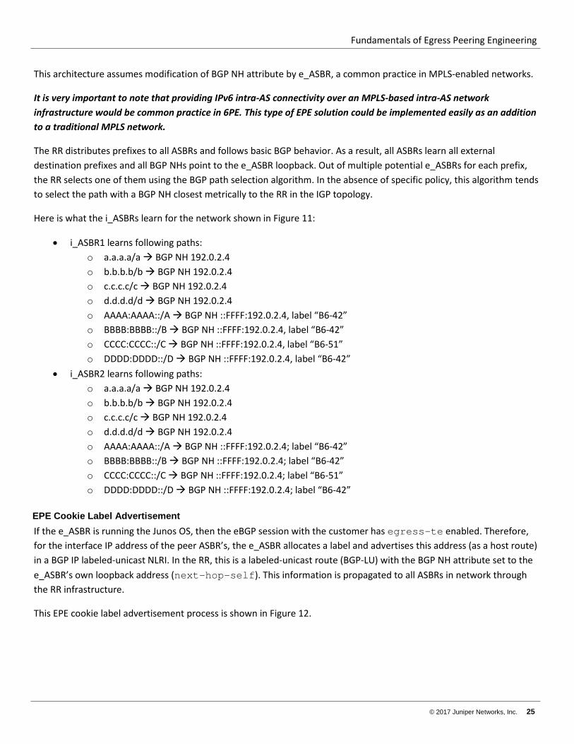
This architecture assumes modification of BGP NH attribute by e_ASBR, a common practice in MPLS-enabled networks.
It is very important to note that providing IPv6 intra-AS connectivity over an MPLS-based intra-AS network infrastructure would be common practice in 6PE. This type of EPE solution could be implemented easily as an addition to a traditional MPLS network.
The RR distributes prefixes to all ASBRs and follows basic BGP behavior. As a result, all ASBRs learn all external destination prefixes and all BGP NHs point to the e_ASBR loopback. Out of multiple potential e_ASBRs for each prefix, the RR selects one of them using the BGP path selection algorithm. In the absence of specific policy, this algorithm tends to select the path with a BGP NH closest metrically to the RR in the IGP topology.
Here is what the i_ASBRs learn for the network shown in Figure 11:
• i_ASBR1 learns following paths: o a.a.a.a/a BGP NH 192.0.2.4 o b.b.b.b/b BGP NH 192.0.2.4 o c.c.c.c/c BGP NH 192.0.2.4 o d.d.d.d/d BGP NH 192.0.2.4 o AAAA:AAAA::/A BGP NH ::FFFF:192.0.2.4, label “B6-42” o BBBB:BBBB::/B BGP NH ::FFFF:192.0.2.4, label “B6-42” o CCCC:CCCC::/C BGP NH ::FFFF:192.0.2.4, label “B6-51” o DDDD:DDDD::/D BGP NH ::FFFF:192.0.2.4, label “B6-42”
• i_ASBR2 learns following paths: o a.a.a.a/a BGP NH 192.0.2.4 o b.b.b.b/b BGP NH 192.0.2.4 o c.c.c.c/c BGP NH 192.0.2.4 o d.d.d.d/d BGP NH 192.0.2.4 o AAAA:AAAA::/A BGP NH ::FFFF:192.0.2.4; label “B6-42” o BBBB:BBBB::/B BGP NH ::FFFF:192.0.2.4; label “B6-42” o CCCC:CCCC::/C BGP NH ::FFFF:192.0.2.4; label “B6-51” o DDDD:DDDD::/D BGP NH ::FFFF:192.0.2.4; label “B6-42”
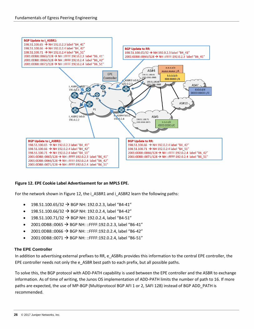
EPE Cookie Label Advertisement If the e_ASBR is running the Junos OS, then the eBGP session with the customer has egress-te enabled. Therefore, for the interface IP address of the peer ASBR’s, the e_ASBR allocates a label and advertises this address (as a host route) in a BGP IP labeled-unicast NLRI. In the RR, this is a labeled-unicast route (BGP-LU) with the BGP NH attribute set to the e_ASBR’s own loopback address (next-hop-self). This information is propagated to all ASBRs in network through the RR infrastructure.
This EPE cookie label advertisement process is shown in Figure 12.
Fundamentals of Egress Peering Engineering
26 © 2017 Juniper Networks, Inc.
Figure 12. EPE Cookie Label Advertisement for an MPLS EPE.
For the network shown in Figure 12, the i_ASBR1 and i_ASBR2 learn the following paths:
• 198.51.100.65/32 BGP NH: 192.0.2.3, label “B4-41” • 198.51.100.66/32 BGP NH: 192.0.2.4, label “B4-42” • 198.51.100.71/32 BGP NH: 192.0.2.4, label “B4-51” • 2001:0DB8::0065 BGP NH: ::FFFF:192.0.2.3, label “B6-41” • 2001:0DB8::0066 BGP NH: ::FFFF:192.0.2.4, label “B6-42” • 2001:0DB8::0071 BGP NH: ::FFFF:192.0.2.4, label “B6-51”
The EPE Controller In addition to advertising external prefixes to RR, e_ASBRs provides this information to the central EPE controller, the EPE controller needs not only the e_ASBR best path to each prefix, but all possible paths.
To solve this, the BGP protocol with ADD-PATH capability is used between the EPE controller and the ASBR to exchange information. As of time of writing, the Junos OS implementation of ADD-PATH limits the number of path to 16. If more paths are expected, the use of MP-BGP (Multiprotocol BGP AFI 1 or 2, SAFI 128) instead of BGP ADD_PATH is recommended.
Fundamentals of Egress Peering Engineering
© 2017 Juniper Networks, Inc. 27
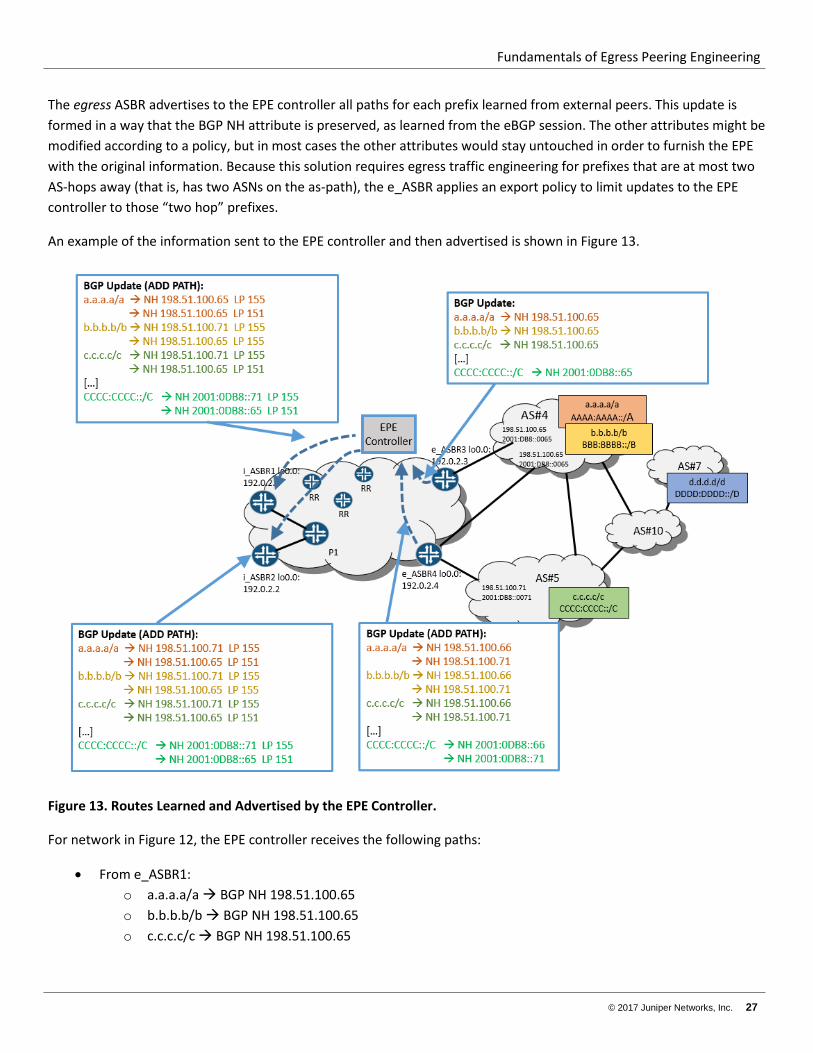
The egress ASBR advertises to the EPE controller all paths for each prefix learned from external peers. This update is formed in a way that the BGP NH attribute is preserved, as learned from the eBGP session. The other attributes might be modified according to a policy, but in most cases the other attributes would stay untouched in order to furnish the EPE with the original information. Because this solution requires egress traffic engineering for prefixes that are at most two AS-hops away (that is, has two ASNs on the as-path), the e_ASBR applies an export policy to limit updates to the EPE controller to those “two hop” prefixes.
An example of the information sent to the EPE controller and then advertised is shown in Figure 13.
Figure 13. Routes Learned and Advertised by the EPE Controller.
For network in Figure 12, the EPE controller receives the following paths:
• From e_ASBR1: o a.a.a.a/a BGP NH 198.51.100.65 o b.b.b.b/b BGP NH 198.51.100.65 o c.c.c.c/c BGP NH 198.51.100.65
Fundamentals of Egress Peering Engineering
28 © 2017 Juniper Networks, Inc.
o AAAA:AAAA::/A BGP NH 2001:0DB8::0065 o BBBB:BBBB::/B BGP NH 2001:0DB8::0065 o CCCC:CCCC::/C BGP NH 2001:0DB8::0065
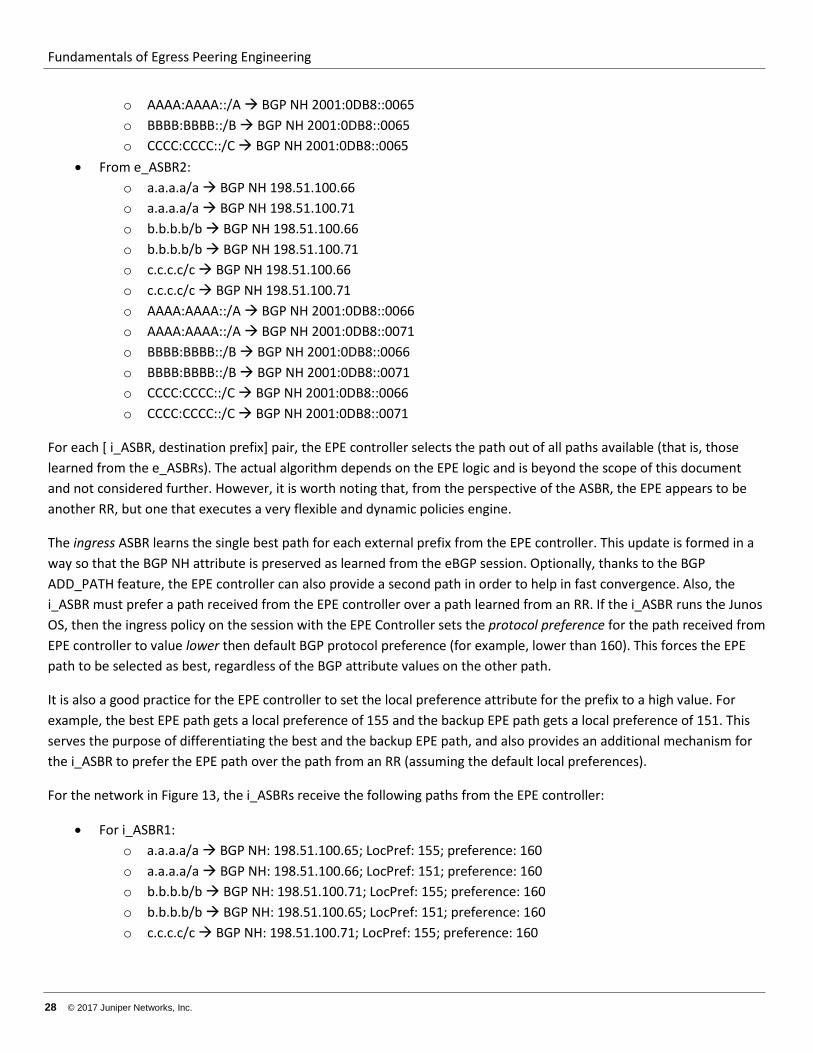
• From e_ASBR2: o a.a.a.a/a BGP NH 198.51.100.66 o a.a.a.a/a BGP NH 198.51.100.71 o b.b.b.b/b BGP NH 198.51.100.66 o b.b.b.b/b BGP NH 198.51.100.71 o c.c.c.c/c BGP NH 198.51.100.66 o c.c.c.c/c BGP NH 198.51.100.71 o AAAA:AAAA::/A BGP NH 2001:0DB8::0066 o AAAA:AAAA::/A BGP NH 2001:0DB8::0071 o BBBB:BBBB::/B BGP NH 2001:0DB8::0066 o BBBB:BBBB::/B BGP NH 2001:0DB8::0071 o CCCC:CCCC::/C BGP NH 2001:0DB8::0066 o CCCC:CCCC::/C BGP NH 2001:0DB8::0071
For each [ i_ASBR, destination prefix] pair, the EPE controller selects the path out of all paths available (that is, those learned from the e_ASBRs). The actual algorithm depends on the EPE logic and is beyond the scope of this document and not considered further. However, it is worth noting that, from the perspective of the ASBR, the EPE appears to be another RR, but one that executes a very flexible and dynamic policies engine.
The ingress ASBR learns the single best path for each external prefix from the EPE controller. This update is formed in a way so that the BGP NH attribute is preserved as learned from the eBGP session. Optionally, thanks to the BGP ADD_PATH feature, the EPE controller can also provide a second path in order to help in fast convergence. Also, the i_ASBR must prefer a path received from the EPE controller over a path learned from an RR. If the i_ASBR runs the Junos OS, then the ingress policy on the session with the EPE Controller sets the protocol preference for the path received from EPE controller to value lower then default BGP protocol preference (for example, lower than 160). This forces the EPE path to be selected as best, regardless of the BGP attribute values on the other path.
It is also a good practice for the EPE controller to set the local preference attribute for the prefix to a high value. For example, the best EPE path gets a local preference of 155 and the backup EPE path gets a local preference of 151. This serves the purpose of differentiating the best and the backup EPE path, and also provides an additional mechanism for the i_ASBR to prefer the EPE path over the path from an RR (assuming the default local preferences).
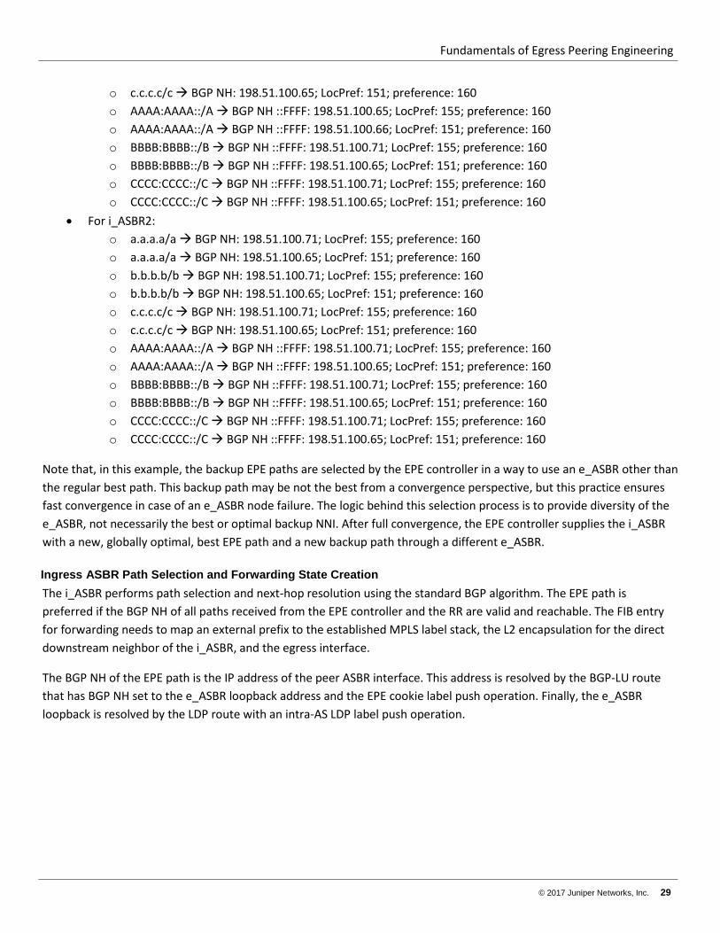
For the network in Figure 13, the i_ASBRs receive the following paths from the EPE controller:
• For i_ASBR1: o a.a.a.a/a BGP NH: 198.51.100.65; LocPref: 155; preference: 160 o a.a.a.a/a BGP NH: 198.51.100.66; LocPref: 151; preference: 160 o b.b.b.b/b BGP NH: 198.51.100.71; LocPref: 155; preference: 160 o b.b.b.b/b BGP NH: 198.51.100.65; LocPref: 151; preference: 160 o c.c.c.c/c BGP NH: 198.51.100.71; LocPref: 155; preference: 160
Fundamentals of Egress Peering Engineering
© 2017 Juniper Networks, Inc. 29
o c.c.c.c/c BGP NH: 198.51.100.65; LocPref: 151; preference: 160 o AAAA:AAAA::/A BGP NH ::FFFF: 198.51.100.65; LocPref: 155; preference: 160 o AAAA:AAAA::/A BGP NH ::FFFF: 198.51.100.66; LocPref: 151; preference: 160 o BBBB:BBBB::/B BGP NH ::FFFF: 198.51.100.71; LocPref: 155; preference: 160 o BBBB:BBBB::/B BGP NH ::FFFF: 198.51.100.65; LocPref: 151; preference: 160 o CCCC:CCCC::/C BGP NH ::FFFF: 198.51.100.71; LocPref: 155; preference: 160 o CCCC:CCCC::/C BGP NH ::FFFF: 198.51.100.65; LocPref: 151; preference: 160
• For i_ASBR2: o a.a.a.a/a BGP NH: 198.51.100.71; LocPref: 155; preference: 160 o a.a.a.a/a BGP NH: 198.51.100.65; LocPref: 151; preference: 160 o b.b.b.b/b BGP NH: 198.51.100.71; LocPref: 155; preference: 160 o b.b.b.b/b BGP NH: 198.51.100.65; LocPref: 151; preference: 160 o c.c.c.c/c BGP NH: 198.51.100.71; LocPref: 155; preference: 160 o c.c.c.c/c BGP NH: 198.51.100.65; LocPref: 151; preference: 160 o AAAA:AAAA::/A BGP NH ::FFFF: 198.51.100.71; LocPref: 155; preference: 160 o AAAA:AAAA::/A BGP NH ::FFFF: 198.51.100.65; LocPref: 151; preference: 160 o BBBB:BBBB::/B BGP NH ::FFFF: 198.51.100.71; LocPref: 155; preference: 160 o BBBB:BBBB::/B BGP NH ::FFFF: 198.51.100.65; LocPref: 151; preference: 160 o CCCC:CCCC::/C BGP NH ::FFFF: 198.51.100.71; LocPref: 155; preference: 160 o CCCC:CCCC::/C BGP NH ::FFFF: 198.51.100.65; LocPref: 151; preference: 160
Note that, in this example, the backup EPE paths are selected by the EPE controller in a way to use an e_ASBR other than the regular best path. This backup path may be not the best from a convergence perspective, but this practice ensures fast convergence in case of an e_ASBR node failure. The logic behind this selection process is to provide diversity of the e_ASBR, not necessarily the best or optimal backup NNI. After full convergence, the EPE controller supplies the i_ASBR with a new, globally optimal, best EPE path and a new backup path through a different e_ASBR.
Ingress ASBR Path Selection and Forwarding State Creation The i_ASBR performs path selection and next-hop resolution using the standard BGP algorithm. The EPE path is preferred if the BGP NH of all paths received from the EPE controller and the RR are valid and reachable. The FIB entry for forwarding needs to map an external prefix to the established MPLS label stack, the L2 encapsulation for the direct downstream neighbor of the i_ASBR, and the egress interface.
The BGP NH of the EPE path is the IP address of the peer ASBR interface. This address is resolved by the BGP-LU route that has BGP NH set to the e_ASBR loopback address and the EPE cookie label push operation. Finally, the e_ASBR loopback is resolved by the LDP route with an intra-AS LDP label push operation.
Fundamentals of Egress Peering Engineering
30 © 2017 Juniper Networks, Inc.
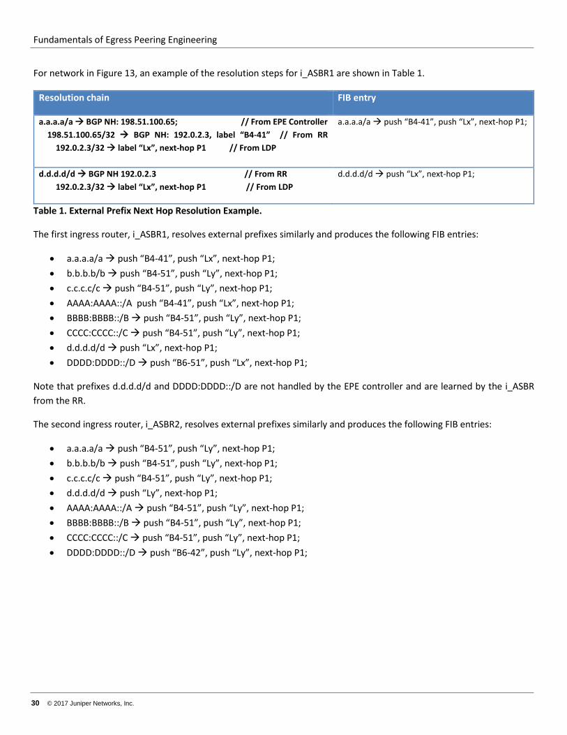
For network in Figure 13, an example of the resolution steps for i_ASBR1 are shown in Table 1.
Resolution chain FIB entry
a.a.a.a/a BGP NH: 198.51.100.65; // From EPE Controller 198.51.100.65/32 BGP NH: 192.0.2.3, label “B4-41” // From RR 192.0.2.3/32 label “Lx”, next-hop P1 // From LDP
a.a.a.a/a push “B4-41”, push “Lx”, next-hop P1;
d.d.d.d/d BGP NH 192.0.2.3 // From RR 192.0.2.3/32 label “Lx”, next-hop P1 // From LDP
d.d.d.d/d push “Lx”, next-hop P1;
Table 1. External Prefix Next Hop Resolution Example.
The first ingress router, i_ASBR1, resolves external prefixes similarly and produces the following FIB entries:
• a.a.a.a/a push “B4-41”, push “Lx”, next-hop P1; • b.b.b.b/b push “B4-51”, push “Ly”, next-hop P1; • c.c.c.c/c push “B4-51”, push “Ly”, next-hop P1; • AAAA:AAAA::/A push “B4-41”, push “Lx”, next-hop P1; • BBBB:BBBB::/B push “B4-51”, push “Ly”, next-hop P1; • CCCC:CCCC::/C push “B4-51”, push “Ly”, next-hop P1; • d.d.d.d/d push “Lx”, next-hop P1; • DDDD:DDDD::/D push “B6-51”, push “Lx”, next-hop P1;
Note that prefixes d.d.d.d/d and DDDD:DDDD::/D are not handled by the EPE controller and are learned by the i_ASBR from the RR.
The second ingress router, i_ASBR2, resolves external prefixes similarly and produces the following FIB entries:
• a.a.a.a/a push “B4-51”, push “Ly”, next-hop P1; • b.b.b.b/b push “B4-51”, push “Ly”, next-hop P1; • c.c.c.c/c push “B4-51”, push “Ly”, next-hop P1; • d.d.d.d/d push “Ly”, next-hop P1; • AAAA:AAAA::/A push “B4-51”, push “Ly”, next-hop P1; • BBBB:BBBB::/B push “B4-51”, push “Ly”, next-hop P1; • CCCC:CCCC::/C push “B4-51”, push “Ly”, next-hop P1; • DDDD:DDDD::/D push “B6-42”, push “Ly”, next-hop P1;
Fundamentals of Egress Peering Engineering
© 2017 Juniper Networks, Inc. 31
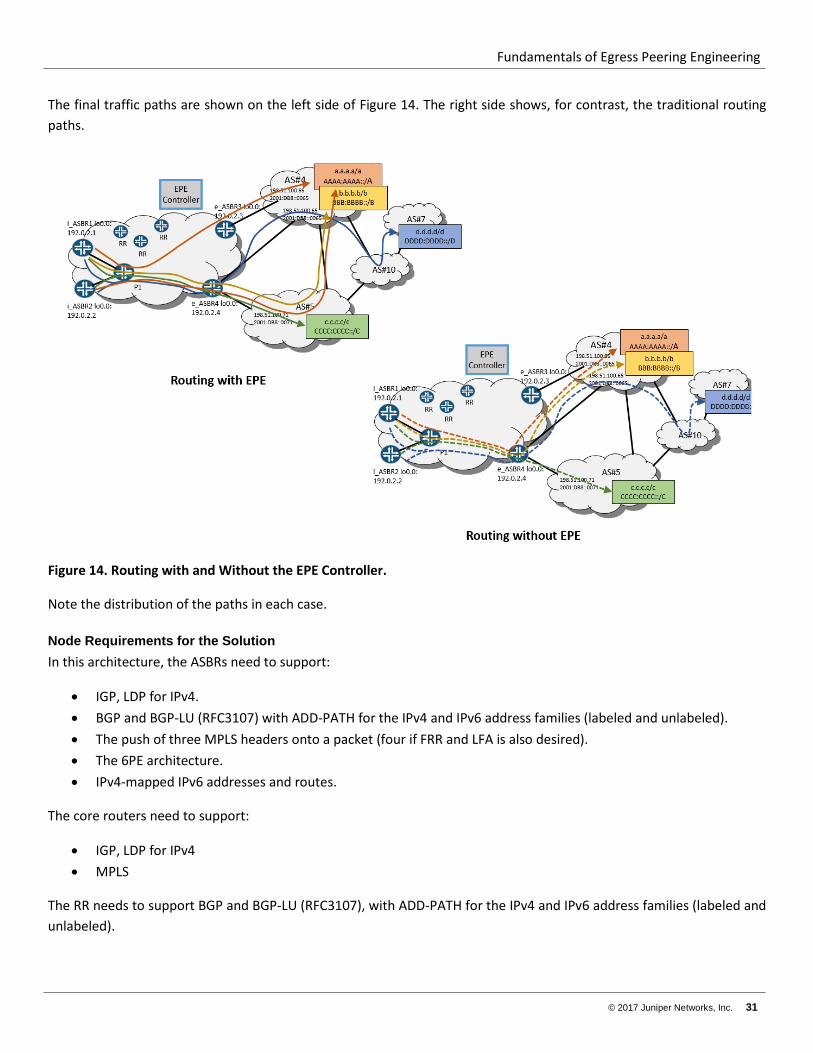
The final traffic paths are shown on the left side of Figure 14. The right side shows, for contrast, the traditional routing paths.
Figure 14. Routing with and Without the EPE Controller.
Note the distribution of the paths in each case.
Node Requirements for the Solution In this architecture, the ASBRs need to support:
• IGP, LDP for IPv4. • BGP and BGP-LU (RFC3107) with ADD-PATH for the IPv4 and IPv6 address families (labeled and unlabeled). • The push of three MPLS headers onto a packet (four if FRR and LFA is also desired). • The 6PE architecture. • IPv4-mapped IPv6 addresses and routes.
The core routers need to support:
• IGP, LDP for IPv4 • MPLS
The RR needs to support BGP and BGP-LU (RFC3107), with ADD-PATH for the IPv4 and IPv6 address families (labeled and unlabeled).
Fundamentals of Egress Peering Engineering
32 © 2017 Juniper Networks, Inc.
The EPE controller needs to support BGP with ADD-PATH for the IPv4 and IPv6 address families (labeled and unlabeled).
Redundancy, Convergence and Fast Restoration This architecture has three major failure concerns. The NNI link itself could fail, or the e-ASBR could fail, or the intra-AS links or nodes could fail. All three have different ways to supply redundancy, convergence, and fast path restoration.
The NNI Failure Case
Failure of an NNI would be detected as either an interface down event or an eBGP session down event. In both cases, the impacted e_ASBR would withdraw the affected prefixes from the RR and from the EPE controller. The e_ASBR also would withdraw the path to the peer ASBR interface’s IP address that conveys the EPE cookie from the RR.
One of the two paths learned by the i_ASBR from the EPE controller by way of BGP ADD-PATH is preferred to the other path. The preferred path—or both paths—might point to the faulty NNI. If the impacted path is the active one, then the i_ASBR, depending of the exact sequence of routing update propagations, would do one of the following:
• If the EPE cookie path withdrawal in comes first, then o The i_ASBR invalidates the path because the BGP NH becomes unresolvable. In this case, the second path that had been learned from the EPE controller becomes active and is used for forwarding. o The EPE controller replaces the impacted path with new best path with its Local Preference equal to 1. The backup path might need to be replaced as well, in order to preserve a diverse e_ASBR condition.
• If the BGP prefix path withdrawal comes first, then the EPE controller withdraws the invalid path and replaces it with a new best path. As before, the backup path might need to be replaced as well to preserve a diverse e_ASBR condition.
This procedure requires failure propagation over the network from the e_ASBR all the way to the i_ASBR. This action might take tens or even hundreds of milliseconds. During this interval, traffic might be lost. In order to reduce time of traffic loss, local protection at point of failure is needed. In the Junos OS, the egress-te feature enables this protection. See http://www.juniper.net/techpubs/en_US/junos16.1/topics/task/configuration/configuring-egress-te-using-bgp-lu.html for more information.
If an NNI fails, the adjacent e_ASBR sends traffic to one of the following:
• Another local NNI. • Another NNI on another e_ASBR. This is done by switching traffic from an LDP LSP tunnel to a backup e_ASBR
and pushing the EPE cookie label (learned from an RR) that points to this other NNI.
This technique reduces traffic loss time to the tens of milliseconds.
The e_ASBR Failure Case
Failure of an e_ASBR uses a network convergence process similar to an NNI failure. The only difference is that, in addition to BGP routes withdrawal, the IGP route leading to the e_ASBR loopback address and its associated LSP are also removed. Because an IGP is usually faster than BGP to converge, removal of the e_ASBR loopback address and LSP is the initial event seen by i_ASBR. This event deactivates all of the BGP paths that use this address. It also deactivates the BGP
Fundamentals of Egress Peering Engineering
© 2017 Juniper Networks, Inc. 33
NH. All the EPE cookie routes learned from this e_ASBR and all external prefixes learned from the RR that has this BGP NH. Recursively, all routes from the EPE controller resolved by the inactive EPE cookie routs are deactivated.
Because an EPE controller provides two diverse routes to reach NNIs for each prefix, an i_ASBR locally switches traffic to the backup NNI.
Finally, when the EPE controller calculates a new “best exit” NNI and a new different backup NNI, the controller updates i_ASBR with this information, which then replaces the two old BGP routes.
The Inta_AS Links or Internal Node Failures Case
Failure of intra-AS links of internal nodes are primarily handled by simple IGP convergence. Optionally, this process could be augmented by BFD in order to speed up detection of some types of failures. For fast restoration, the network could use LFA or R-LFA, augmented by an explicit or dynamic (that is, TI-FRR) backup LSP.
Fundamentals of Egress Peering Engineering
34 © 2017 Juniper Networks, Inc.
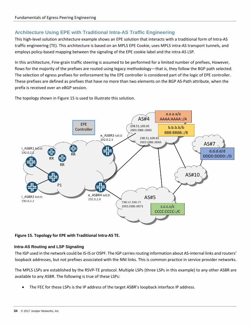
Architecture Using EPE with Traditional Intra-AS Traffic Engineering This high-level solution architecture example shows an EPE solution that interacts with a traditional form of Intra-AS traffic engineering (TE). This architecture is based on an MPLS EPE Cookie, uses MPLS intra-AS transport tunnels, and employs policy-based mapping between the signaling of the EPE cookie label and the intra-AS LSP.
In this architecture, Fine-grain traffic steering is assumed to be performed for a limited number of prefixes, However, flows for the majority of the prefixes are routed using legacy methodology—that is, they follow the BGP path selected. The selection of egress prefixes for enforcement by the EPE controller is considered part of the logic of EPE controller. These prefixes are defined as prefixes that have no more than two elements on the BGP AS-Path attribute, when the prefix is received over an eBGP session.
The topology shown in Figure 15 is used to illustrate this solution.
Figure 15. Topology for EPE with Traditional Intra-AS TE.
Intra-AS Routing and LSP Signaling The IGP used in the network could be IS-IS or OSPF. The IGP carries routing information about AS-internal links and routers’ loopback addresses, but not prefixes associated with the NNI links. This is common practice in service provider networks.
The MPLS LSPs are established by the RSVP-TE protocol. Multiple LSPs (three LSPs in this example) to any other ASBR are available to any ASBR. The following is true of these LSPs:
• The FEC for these LSPs is the IP address of the target ASBR’s loopback interface IP address.
Fundamentals of Egress Peering Engineering
© 2017 Juniper Networks, Inc. 35
• The first LSP is low-latency, and: o Its name matches the regular expression (regex) “.*-LL$” and ends with “-LL”. o Its EXP bits are fixed and set to Expedited Forwarding (EF) per-hop behavior (PHB). o Is routed along the shortest-path (that is, not using CSPF) to ensure low latency. o Is set up and holds priorities that ensure it could preempt other LSP. o Is signaled with bandwidth requirements derived from LSP Auto-Bandwidth statistics.
• The second LSP has a protected and guaranteed bandwidth, and: o Its name matches the regex “.*-PB$” and ends with “-PB”. o Its EXP bits are derived from the payload traffic PHB. o Is set up and holds priorities that ensures it can be preempted by a low-latency LSP. o Is signaled for node-link facility backup. o Has the route for the LSP calculated by an i_ASBR using local Constrained Shortest Path First (CSPF) or by
a Path Computation Engine (PCE). • The third LSP has a less-than-best-effort classification, and:
o Its name matches the regex “.*-LBE$”and ends with “-LBE”. o Its EXP bits are fixed and set to Less-than-Best-Effort (LBE) PHB. LBE traffic is scheduled from the same
queue (the PHB Scheduling Class, or PSC) as Best-Effort (BE) but LBE traffic is subject to a more aggressive Random Early Discard (RED) drop profile.
o Is routed along a path calculated by an i_ASBR using local CSPF or by PCE. o Is set up and holds priorities that ensure it can be preempted by a low-latency LSP or a protected-
guaranteed-BW LSP.
BFD is used to reduce failure detection and traffic restoration times for failures of internal links or transit nodes.
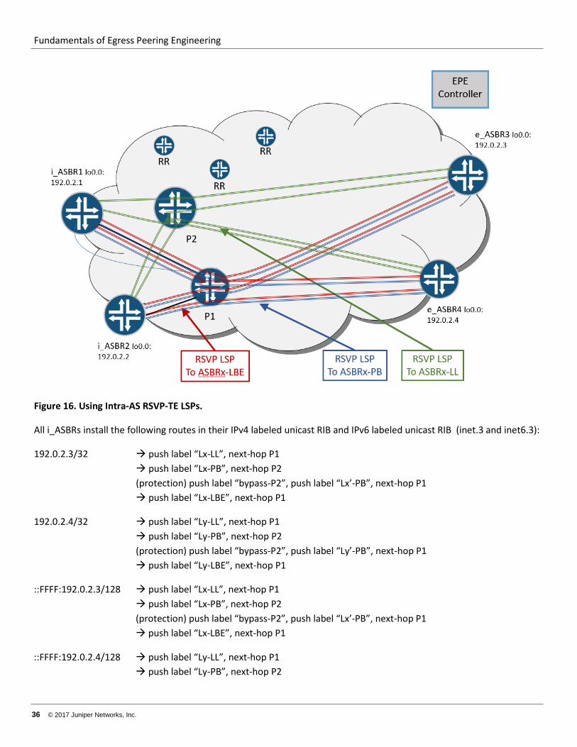
Figure 16 shows that i_ASBR1 and i_ASBR2 both have three LSPs to FEC 192.0.2.3/32, the loopback address of e_ASBR3, and another set of LSPs to FEC 192.0.2.4/32, the loopback address of e_ASBR4.
Fundamentals of Egress Peering Engineering
36 © 2017 Juniper Networks, Inc.
Figure 16. Using Intra-AS RSVP-TE LSPs.
All i_ASBRs install the following routes in their IPv4 labeled unicast RIB and IPv6 labeled unicast RIB (inet.3 and inet6.3):
192.0.2.3/32 push label “Lx-LL”, next-hop P1 push label “Lx-PB”, next-hop P2 (protection) push label “bypass-P2”, push label “Lx’-PB”, next-hop P1 push label “Lx-LBE”, next-hop P1
192.0.2.4/32 push label “Ly-LL”, next-hop P1 push label “Ly-PB”, next-hop P2 (protection) push label “bypass-P2”, push label “Ly’-PB”, next-hop P1 push label “Ly-LBE”, next-hop P1
::FFFF:192.0.2.3/128 push label “Lx-LL”, next-hop P1 push label “Lx-PB”, next-hop P2 (protection) push label “bypass-P2”, push label “Lx’-PB”, next-hop P1 push label “Lx-LBE”, next-hop P1
::FFFF:192.0.2.4/128 push label “Ly-LL”, next-hop P1 push label “Ly-PB”, next-hop P2
Fundamentals of Egress Peering Engineering
© 2017 Juniper Networks, Inc. 37
(protection) push label “bypass-P2”, push label “Ly’-PB”, next hop P1 push label “Ly-LBE”, next-hop P1
All three LSPs sharing the same FEC (the e_ASBR loopback IP address) form an ECMP group because they share the same metric/cost from a routing perspective.
Note that for the Junos OS, installation of IPv4-mapped IPv6 routes in the inet6.3 table requires explicit configuration, namely with set protocols mpls ipv6-tunneling.
BGP Infrastructure The regional Route Reflectors (RRs) are used to distribute routing information to all ASBRs in the network. Each RR services sub-set of ASBRs located in close geographic proximity, and supplies at a minimum IPv4 unicast, IPv6 unicast, IPv4 labeled unicast and IPv6 labeled-unicast routes. All RRs are fully meshed by iBGP sessions to propagate routing information to all ASBRs. This infrastructure is commonly used in service provider networks.
In addition to this traditional RR infrastructure, the central EPE controller is installed in the network and uses iBGP to reach all ASBRs. This iBGP architecture is shown in Figure 17.
Fundamentals of Egress Peering Engineering
38 © 2017 Juniper Networks, Inc.
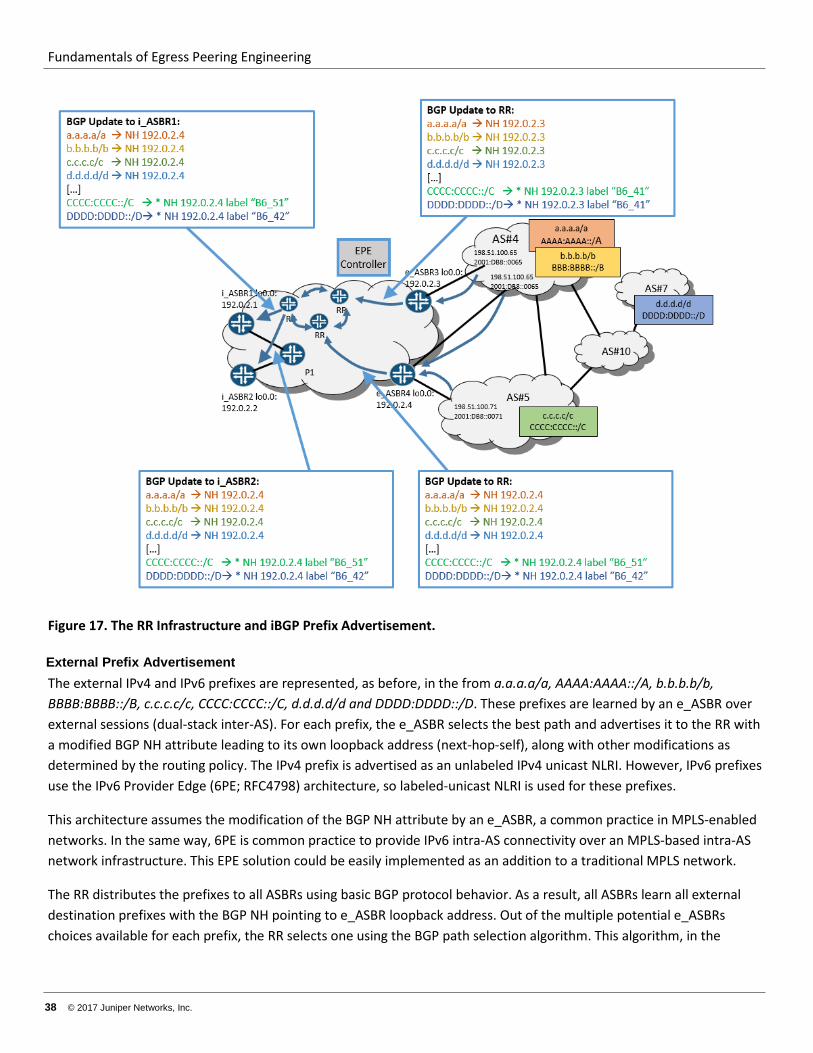
Figure 17. The RR Infrastructure and iBGP Prefix Advertisement.
External Prefix Advertisement The external IPv4 and IPv6 prefixes are represented, as before, in the from a.a.a.a/a, AAAA:AAAA::/A, b.b.b.b/b, BBBB:BBBB::/B, c.c.c.c/c, CCCC:CCCC::/C, d.d.d.d/d and DDDD:DDDD::/D. These prefixes are learned by an e_ASBR over external sessions (dual-stack inter-AS). For each prefix, the e_ASBR selects the best path and advertises it to the RR with a modified BGP NH attribute leading to its own loopback address (next-hop-self), along with other modifications as determined by the routing policy. The IPv4 prefix is advertised as an unlabeled IPv4 unicast NLRI. However, IPv6 prefixes use the IPv6 Provider Edge (6PE; RFC4798) architecture, so labeled-unicast NLRI is used for these prefixes.
This architecture assumes the modification of the BGP NH attribute by an e_ASBR, a common practice in MPLS-enabled networks. In the same way, 6PE is common practice to provide IPv6 intra-AS connectivity over an MPLS-based intra-AS network infrastructure. This EPE solution could be easily implemented as an addition to a traditional MPLS network.
The RR distributes the prefixes to all ASBRs using basic BGP protocol behavior. As a result, all ASBRs learn all external destination prefixes with the BGP NH pointing to e_ASBR loopback address. Out of the multiple potential e_ASBRs choices available for each prefix, the RR selects one using the BGP path selection algorithm. This algorithm, in the
Fundamentals of Egress Peering Engineering
© 2017 Juniper Networks, Inc. 39
absence of a policy to the contrary, tends to select the path with a BGP NH closest metrically to the RR in the IGP topology.
For the network in Figure 17:
• i_ASBR1 learns the following paths: o a.a.a.a/a BGP NH 192.0.2.4 o b.b.b.b/b BGP NH 192.0.2.4 o c.c.c.c/c BGP NH 192.0.2.4 o d.d.d.d/d BGP NH 192.0.2.4 o AAAA:AAAA::/A BGP NH ::FFFF:192.0.2.4, label “B6-42” o BBBB:BBBB::/B BGP NH ::FFFF:192.0.2.4, label “B6-42” o CCCC:CCCC::/C BGP NH ::FFFF:192.0.2.4, label “B6-51” o DDDD:DDDD::/D BGP NH ::FFFF:192.0.2.4, label “B6-42”
• i_ASBR2 learns the following paths: o a.a.a.a/a BGP NH 192.0.2.4 o b.b.b.b/b BGP NH 192.0.2.4 o c.c.c.c/c BGP NH 192.0.2.4 o d.d.d.d/d BGP NH 192.0.2.4 o AAAA:AAAA::/A BGP NH ::FFFF:192.0.2.4; label “B6-42” o BBBB:BBBB::/B BGP NH ::FFFF:192.0.2.4; label “B6-42” o CCCC:CCCC::/C BGP NH ::FFFF:192.0.2.4; label “B6-51” o DDDD:DDDD::/D BGP NH ::FFFF:192.0.2.4; label “B6-42”
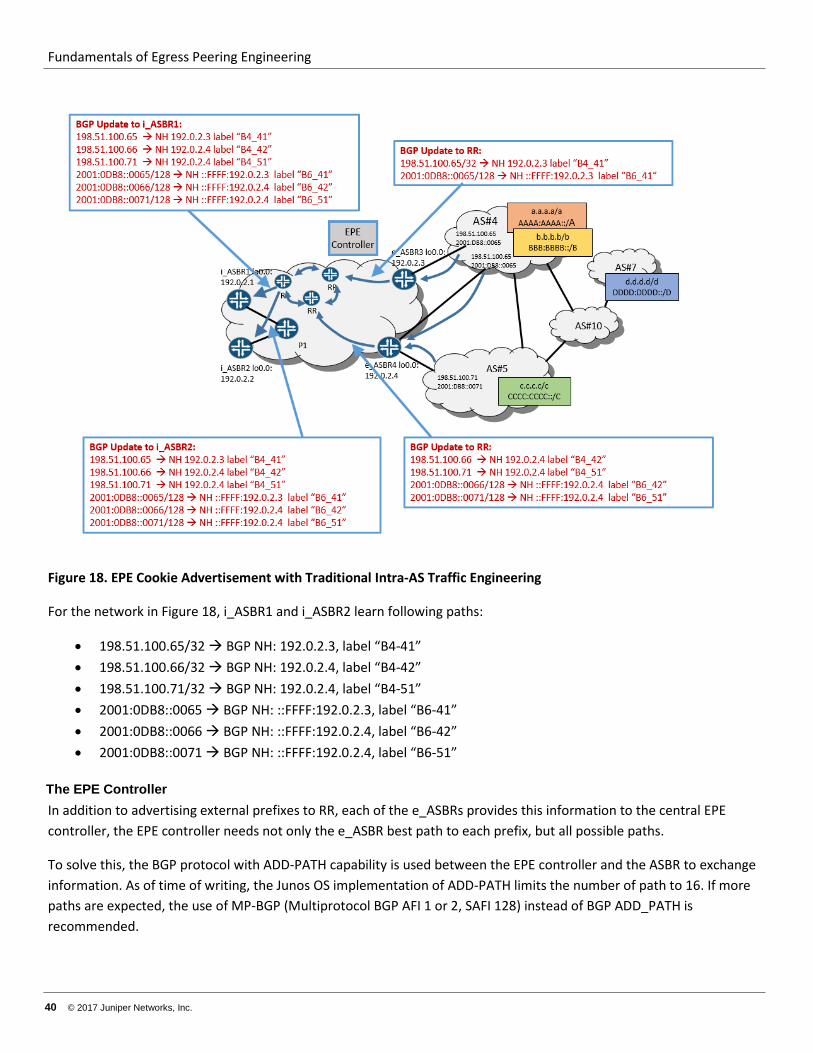
EPE Cookie Label Advertisement If the e_ASBR is running the Junos OS, then the eBGP session has egress-te enabled. Therefore, for the interface IP address of the peer ASBR’s, the e_ASBR allocates a label and advertises this address (as a host route). In the RR, this is a labeled-unicast route (BGP-LU) with the BGP NH attribute set to the e_ASBR’s own loopback address (next-hop-self). This information is propagated to all ASBRs in network through the RR infrastructure.
This EPE cookie label advertisement process is shown in Figure 18.
Fundamentals of Egress Peering Engineering
40 © 2017 Juniper Networks, Inc.
Figure 18. EPE Cookie Advertisement with Traditional Intra-AS Traffic Engineering
For the network in Figure 18, i_ASBR1 and i_ASBR2 learn following paths:
• 198.51.100.65/32 BGP NH: 192.0.2.3, label “B4-41” • 198.51.100.66/32 BGP NH: 192.0.2.4, label “B4-42” • 198.51.100.71/32 BGP NH: 192.0.2.4, label “B4-51” • 2001:0DB8::0065 BGP NH: ::FFFF:192.0.2.3, label “B6-41” • 2001:0DB8::0066 BGP NH: ::FFFF:192.0.2.4, label “B6-42” • 2001:0DB8::0071 BGP NH: ::FFFF:192.0.2.4, label “B6-51”
The EPE Controller In addition to advertising external prefixes to RR, each of the e_ASBRs provides this information to the central EPE controller, the EPE controller needs not only the e_ASBR best path to each prefix, but all possible paths.
To solve this, the BGP protocol with ADD-PATH capability is used between the EPE controller and the ASBR to exchange information. As of time of writing, the Junos OS implementation of ADD-PATH limits the number of path to 16. If more paths are expected, the use of MP-BGP (Multiprotocol BGP AFI 1 or 2, SAFI 128) instead of BGP ADD_PATH is recommended.
Fundamentals of Egress Peering Engineering
© 2017 Juniper Networks, Inc. 41
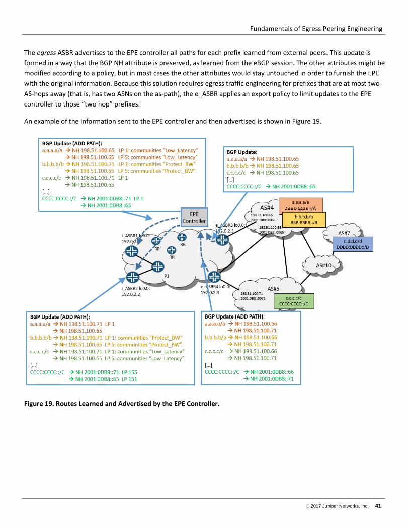
The egress ASBR advertises to the EPE controller all paths for each prefix learned from external peers. This update is formed in a way that the BGP NH attribute is preserved, as learned from the eBGP session. The other attributes might be modified according to a policy, but in most cases the other attributes would stay untouched in order to furnish the EPE with the original information. Because this solution requires egress traffic engineering for prefixes that are at most two AS-hops away (that is, has two ASNs on the as-path), the e_ASBR applies an export policy to limit updates to the EPE controller to those “two hop” prefixes.
An example of the information sent to the EPE controller and then advertised is shown in Figure 19.
Figure 19. Routes Learned and Advertised by the EPE Controller.
Fundamentals of Egress Peering Engineering
42 © 2017 Juniper Networks, Inc.
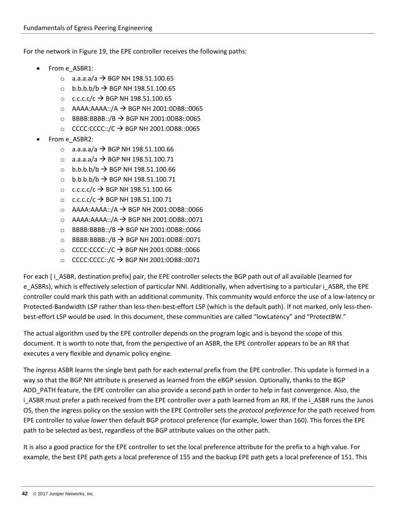
For the network in Figure 19, the EPE controller receives the following paths:
• From e_ASBR1: o a.a.a.a/a BGP NH 198.51.100.65 o b.b.b.b/b BGP NH 198.51.100.65 o c.c.c.c/c BGP NH 198.51.100.65 o AAAA:AAAA::/A BGP NH 2001:0DB8::0065 o BBBB:BBBB::/B BGP NH 2001:0DB8::0065 o CCCC:CCCC::/C BGP NH 2001:0DB8::0065
• From e_ASBR2: o a.a.a.a/a BGP NH 198.51.100.66 o a.a.a.a/a BGP NH 198.51.100.71 o b.b.b.b/b BGP NH 198.51.100.66 o b.b.b.b/b BGP NH 198.51.100.71 o c.c.c.c/c BGP NH 198.51.100.66 o c.c.c.c/c BGP NH 198.51.100.71 o AAAA:AAAA::/A BGP NH 2001:0DB8::0066 o AAAA:AAAA::/A BGP NH 2001:0DB8::0071 o BBBB:BBBB::/B BGP NH 2001:0DB8::0066 o BBBB:BBBB::/B BGP NH 2001:0DB8::0071 o CCCC:CCCC::/C BGP NH 2001:0DB8::0066 o CCCC:CCCC::/C BGP NH 2001:0DB8::0071
For each [ i_ASBR, destination prefix] pair, the EPE controller selects the BGP path out of all available (learned for e_ASBRs), which is effectively selection of particular NNI. Additionally, when advertising to a particular i_ASBR, the EPE controller could mark this path with an additional community. This community would enforce the use of a low-latency or Protected-Bandwidth LSP rather than less-then-best-effort LSP (which is the default path). If not marked, only less-then-best-effort LSP would be used. In this document, these communities are called “lowLatency” and “ProtectBW.”
The actual algorithm used by the EPE controller depends on the program logic and is beyond the scope of this document. It is worth to note that, from the perspective of an ASBR, the EPE controller appears to be an RR that executes a very flexible and dynamic policy engine.
The ingress ASBR learns the single best path for each external prefix from the EPE controller. This update is formed in a way so that the BGP NH attribute is preserved as learned from the eBGP session. Optionally, thanks to the BGP ADD_PATH feature, the EPE controller can also provide a second path in order to help in fast convergence. Also, the i_ASBR must prefer a path received from the EPE controller over a path learned from an RR. If the i_ASBR runs the Junos OS, then the ingress policy on the session with the EPE Controller sets the protocol preference for the path received from EPE controller to value lower then default BGP protocol preference (for example, lower than 160). This forces the EPE path to be selected as best, regardless of the BGP attribute values on the other path.
It is also a good practice for the EPE controller to set the local preference attribute for the prefix to a high value. For example, the best EPE path gets a local preference of 155 and the backup EPE path gets a local preference of 151. This
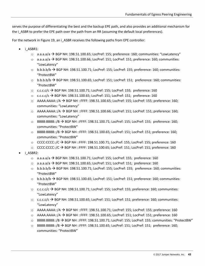
Fundamentals of Egress Peering Engineering
© 2017 Juniper Networks, Inc. 43
serves the purpose of differentiating the best and the backup EPE path, and also provides an additional mechanism for the i_ASBR to prefer the EPE path over the path from an RR (assuming the default local preferences).
For the network in Figure 19, an i_ASBR receives the following paths from EPE controller:
• i_ASBR1: o a.a.a.a/a BGP NH: 198.51.100.65; LocPref: 155; preference: 160; communities: “LowLatency” o a.a.a.a/a BGP NH: 198.51.100.66; LocPref: 151; LocPref: 151; preference: 160; communities:
“LowLatency” o b.b.b.b/b BGP NH: 198.51.100.71; LocPref: 155; LocPref: 155; preference: 160; communities:
“ProtectBW” o b.b.b.b/b BGP NH: 198.51.100.65; LocPref: 151; LocPref: 151; preference: 160; communities:
“ProtectBW” o c.c.c.c/c BGP NH: 198.51.100.71; LocPref: 155; LocPref: 155; preference: 160 o c.c.c.c/c BGP NH: 198.51.100.65; LocPref: 151; LocPref: 151; preference: 160 o AAAA:AAAA::/A BGP NH ::FFFF: 198.51.100.65; LocPref: 155; LocPref: 155; preference: 160;
communities: “LowLatency” o AAAA:AAAA::/A BGP NH ::FFFF: 198.51.100.66; LocPref: 151; LocPref: 151; preference: 160;
communities: “LowLatency” o BBBB:BBBB::/B BGP NH ::FFFF: 198.51.100.71; LocPref: 155; LocPref: 155; preference: 160;
communities: “ProtectBW” o BBBB:BBBB::/B BGP NH ::FFFF: 198.51.100.65; LocPref: 151; LocPref: 151; preference: 160;
communities: “ProtectBW” o CCCC:CCCC::/C BGP NH ::FFFF: 198.51.100.71; LocPref: 155; LocPref: 155; preference: 160 o CCCC:CCCC::/C BGP NH ::FFFF: 198.51.100.65; LocPref: 151; LocPref: 151; preference: 160
• i_ASBR2: o a.a.a.a/a BGP NH: 198.51.100.71; LocPref: 155; LocPref: 155; preference: 160 o a.a.a.a/a BGP NH: 198.51.100.65; LocPref: 151; LocPref: 151; preference: 160 o b.b.b.b/b BGP NH: 198.51.100.71; LocPref: 155; LocPref: 155; preference: 160; communities:
“ProtectBW” o b.b.b.b/b BGP NH: 198.51.100.65; LocPref: 151; LocPref: 151; preference: 160; communities:
“ProtectBW” o c.c.c.c/c BGP NH: 198.51.100.71; LocPref: 155; LocPref: 155; preference: 160; communities:
“LowLatency” o c.c.c.c/c BGP NH: 198.51.100.65; LocPref: 151; LocPref: 151; preference: 160; communities:
“LowLatency” o AAAA:AAAA::/A BGP NH ::FFFF: 198.51.100.71; LocPref: 155; LocPref: 155; preference: 160 o AAAA:AAAA::/A BGP NH ::FFFF: 198.51.100.65; LocPref: 151; LocPref: 151; preference: 160 o BBBB:BBBB::/B BGP NH ::FFFF: 198.51.100.71; LocPref: 155; LocPref: 155; communities: “ProtectBW” o BBBB:BBBB::/B BGP NH ::FFFF: 198.51.100.65; LocPref: 151; LocPref: 151; preference: 160;
communities: “ProtectBW”
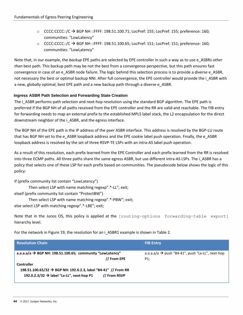
Fundamentals of Egress Peering Engineering
44 © 2017 Juniper Networks, Inc.
o CCCC:CCCC::/C BGP NH ::FFFF: 198.51.100.71; LocPref: 155; LocPref: 155; preference: 160; communities: “LowLatency”
o CCCC:CCCC::/C BGP NH ::FFFF: 198.51.100.65; LocPref: 151; LocPref: 151; preference: 160; communities: “LowLatency”
Note that, in our example, the backup EPE paths are selected by EPE controller in such a way as to use e_ASBRs other than best path. This backup path may be not the best from a convergence perspective, but this path ensures fast convergence in case of an e_ASBR node failure. The logic behind this selection process is to provide a diverse e_ASBR, not necessary the best or optimal backup NNI. After full convergence, the EPE controller would provide the i_ASBR with a new, globally optimal, best EPE path and a new backup path through a diverse e_ASBR.
Ingress ASBR Path Selection and Forwarding State Creation The i_ASBR performs path selection and next-hop resolution using the standard BGP algorithm. The EPE path is preferred if the BGP NH of all paths received from the EPE controller and the RR are valid and reachable. The FIB entry for forwarding needs to map an external prefix to the established MPLS label stack, the L2 encapsulation for the direct downstream neighbor of the i_ASBR, and the egress interface.
The BGP NH of the EPE path is the IP address of the peer ASBR interface. This address is resolved by the BGP-LU route that has BGP NH set to the e_ASBR loopback address and the EPE cookie label push operation. Finally, the e_ASBR loopback address is resolved by the set of three RSVP-TE LSPs with an intra-AS label push operation.
As a result of this resolution, each prefix learned from the EPE Controller and each prefix learned from the RR is resolved into three ECMP paths. All three paths share the same egress ASBR, but use different intra-AS LSPs. The i_ASBR has a policy that selects one of these LSP for each prefix based on communities. The pseudocode below shows the logic of this policy:
If (prefix community list contain “LowLatency”) Then select LSP with name matching regexp”.*-LL”; exit; elseif (prefix community list contain “ProtectBW”) Then select LSP with name matching regexp”.*-PBW”; exit; else select LSP with matching regexp”.*-LBE”; exit;
Note that in the Junos OS, this policy is applied at the [routing-options forwarding-table export] hierarchy level.
For the network in Figure 19, the resolution for an i_ASBR1 example is shown in Table 2.
Resolution Chain FIB Entry
a.a.a.a/a BGP NH: 198.51.100.65; community “LowLatency” // From EPE Controller 198.51.100.65/32 BGP NH: 192.0.2.3, label “B4-41” // From RR 192.0.2.3/32 label “Lx-LL”, next-hop P1 // From RSVP
a.a.a.a/a push “B4-41”, push “Lx-LL”, next-hop P1;
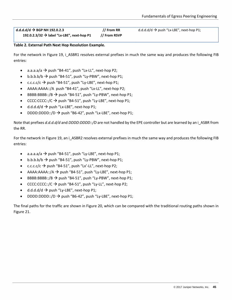
Fundamentals of Egress Peering Engineering
© 2017 Juniper Networks, Inc. 45
d.d.d.d/d BGP NH 192.0.2.3 // From RR 192.0.2.3/32 label “Lx-LBE”, next-hop P1 // From RSVP
d.d.d.d/d push “Lx-LBE”, next-hop P1;
Table 2. External Path Next Hop Resolution Example.
For the network in Figure 19, i_ASBR1 resolves external prefixes in much the same way and produces the following FIB entries:
• a.a.a.a/a push “B4-41”, push “Lx-LL”, next-hop P2; • b.b.b.b/b push “B4-51”, push “Ly-PBW”, next-hop P1; • c.c.c.c/c push “B4-51”, push “Ly-LBE”, next-hop P1; • AAAA:AAAA::/A push “B4-41”, push “Lx-LL”, next-hop P2; • BBBB:BBBB::/B push “B4-51”, push “Ly-PBW”, next-hop P1; • CCCC:CCCC::/C push “B4-51”, push “Ly-LBE”, next-hop P1; • d.d.d.d/d push “Lx-LBE”, next-hop P1; • DDDD:DDDD::/D push “B6-42”, push “Lx-LBE”, next-hop P1;
Note that prefixes d.d.d.d/d and DDDD:DDDD::/D are not handled by the EPE controller but are learned by an i_ASBR from the RR.
For the network in Figure 19, an i_ASBR2 resolves external prefixes in much the same way and produces the following FIB entries:
• a.a.a.a/a push “B4-51”, push “Ly-LBE”, next-hop P1; • b.b.b.b/b push “B4-51”, push “Ly-PBW”, next-hop P1; • c.c.c.c/c push “B4-51”, push “Lx’-LL”, next-hop P2; • AAAA:AAAA::/A push “B4-51”, push “Ly-LBE”, next-hop P1; • BBBB:BBBB::/B push “B4-51”, push “Ly-PBW”, next-hop P1; • CCCC:CCCC::/C push “B4-51”, push “Ly-LL”, next-hop P2; • d.d.d.d/d push “Ly-LBE”, next-hop P1; • DDDD:DDDD::/D push “B6-42”, push “Ly-LBE”, next-hop P1;
The final paths for the traffic are shown in Figure 20, which can be compared with the traditional routing paths shown in Figure 21.
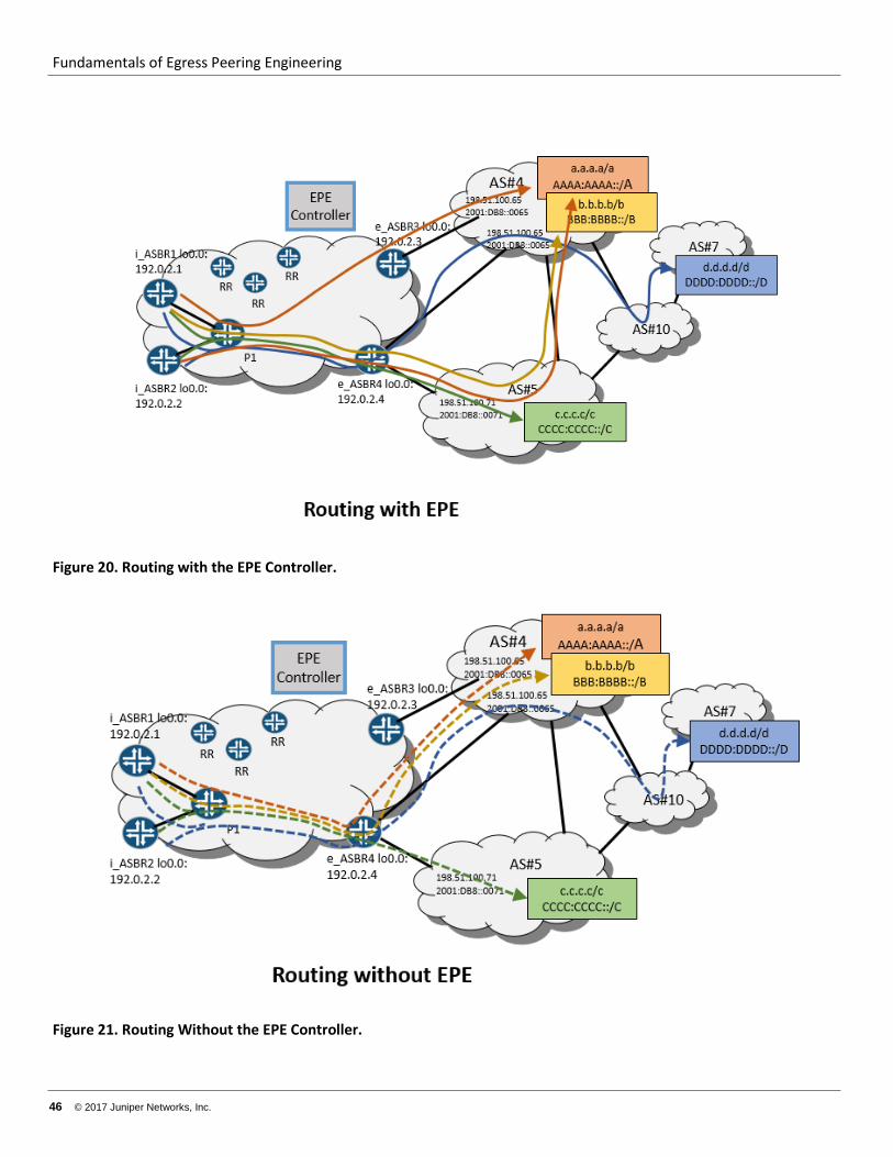
Fundamentals of Egress Peering Engineering
46 © 2017 Juniper Networks, Inc.
Figure 20. Routing with the EPE Controller.
Figure 21. Routing Without the EPE Controller.
Fundamentals of Egress Peering Engineering
© 2017 Juniper Networks, Inc. 47
Node Requirements for the Solution In this architecture, the ASBR nodes need to support:
• IGP, RSVP-TE for IPv4 • BGP and BGP-LU (RFC3107), w/ ADD-PATH for IPv4 and IPv6 address families’ (labeled and not). • Push of 3 MPLS headers onto packet (4 if FRR/LFA is desired) • 6PE architecture • IPv4-mapped IPv6 addresses and routes.
The core routers need to support:
• IGP • RSVP-TE • MPLS
The RR needs to support BGP and BGP-LU (RFC3107), both with ADD-PATH for the IPv4 and IPv6 address families, labeled and unlabeled.
The EPE controller needs to support BGP with ADD-PATH for the IPv4 and IPv6 address families, labeled and unlabeled.
Redundancy, Convergence and Fast Restoration This architecture has three major failure concerns. The NNI link itself could fail, or the e-ASBR could fail, or the intra-AS links or nodes could fail. All three have different ways to supply redundancy, convergence, and fast path restoration.
The NNI Failure Case
Failure of an NNI would be detected as either an interface down event or an eBGP session down event. In both cases, the impacted e_ASBR would withdraw the affected prefixes from the RR and from the EPE controller. The e_ASBR also would withdraw the path to the peer ASBR interface’s IP address that conveys the EPE cookie from the RR.
One of the two paths learned by the i_ASBR from the EPE controller by way of BGP ADD-PATH is preferred to the other path. The preferred path—or both paths—might point to the faulty NNI. If the impacted path is the active one, then the i_ASBR, depending of the exact sequence of routing update propagations, would do one of the following:
• If the EPE cookie path withdrawal in comes first, then o The i_ASBR invalidates the path because the BGP NH becomes unresolvable. In this case, the second path that had been learned from the EPE controller becomes active and is used for forwarding. o The EPE controller replaces the impacted path with new best path with its Local Preference equal to 1. The backup path might need to be replaced as well, in order to preserve a diverse e_ASBR condition.
• If the BGP prefix path withdrawal comes first, then the EPE controller withdraws the invalid path and replaces it with a new best path. As before, the backup path might need to be replaced as well to preserve a diverse e_ASBR condition.
This procedure requires failure propagation over the network from the e_ASBR all the way to the i_ASBR. This action might take tens or even hundreds of milliseconds. During this interval, traffic might be lost. In order to reduce time of
Fundamentals of Egress Peering Engineering
48 © 2017 Juniper Networks, Inc.
traffic loss, local protection at point of failure is needed. In the Junos OS, the egress-te feature enables this protection. See http://www.juniper.net/techpubs/en_US/junos16.1/topics/task/configuration/configuring-egress-te-using-bgp-lu.html for more information.
If an NNI fails, the adjacent e_ASBR sends traffic to one of the following:
• Another local NNI. • Another NNI on another e_ASBR. This is done by switching traffic from an LDP LSP tunnel to a backup e_ASBR
and pushing the EPE cookie label (learned from an RR) that points to this other NNI.
This technique reduces traffic loss time to the tens of milliseconds.
The e_ASBR Failure Case
Failure of an e_ASBR uses a network convergence process similar to an NNI failure. The only difference is that, in addition to BGP routes withdrawal, the IGP route leading to the e_ASBR loopback address and its associated LSP are also removed. Because an IGP is usually faster than BGP to converge, removal of the e_ASBR loopback address and LSP is the initial event seen by i_ASBR. This event deactivates all of the BGP paths that use this address. It also deactivates the BGP NH. All the EPE cookie routes learned from this e_ASBR and all external prefixes learned from the RR that has this BGP NH. Recursively, all routes from the EPE controller resolved by the inactive EPE cookie routs are deactivated.
Because an EPE controller provides two diverse routes to reach NNIs for each prefix, an i_ASBR locally switches traffic to the backup NNI.
Finally, when the EPE controller calculates a new “best exit” NNI and a new different backup NNI, the controller updates i_ASBR with this information, which then replaces the two old BGP routes. The Junos OS provides a solution for LSP “tail-end” local protection using BGP service mirroring in combination with a context label. However, these techniques are not commonly used in networks due to the complexity and lack of required functionality on other vendors’ products.
The Inta_AS Links or Internal Node Failures Case
Failure of intra-AS links of internal nodes are primarily handled by IGP convergence and RSVP error handling. Optionally, this process could be augmented by BFD in order to speed up detection of some types of failures. RSVP LSPs are re-signaled or switched to secondary paths at the i_ASBR in response to receipt of a PATHError message. It takes a few hundreds of milliseconds or even a few full seconds to full recover the traffic flow.
To minimize this loss time, LSPs signaled with local-protection are immediately switched to the bypass LSP at the node directly upstream of the failure (the Point of Local Repair, or PLR). This way traffic using the protected LSP could be restored in a few tens of milliseconds.
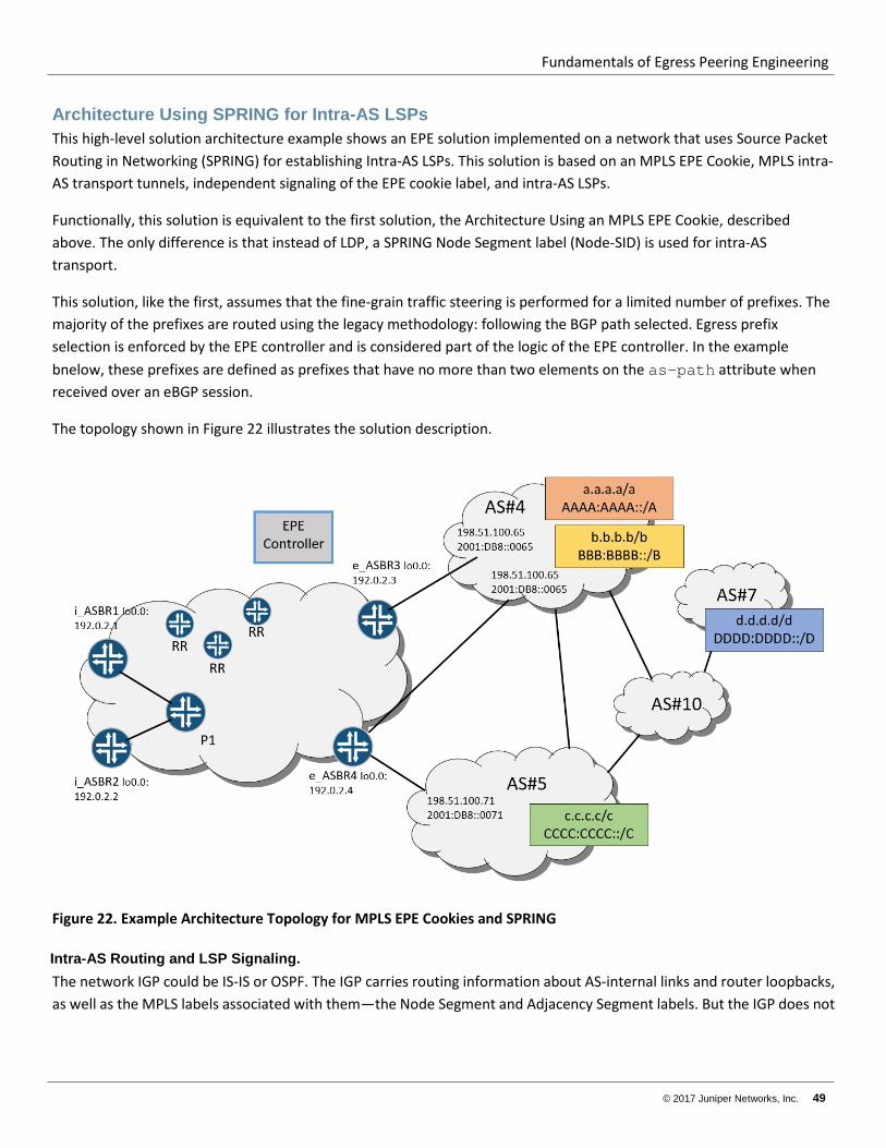
Fundamentals of Egress Peering Engineering
© 2017 Juniper Networks, Inc. 49
Architecture Using SPRING for Intra-AS LSPs This high-level solution architecture example shows an EPE solution implemented on a network that uses Source Packet Routing in Networking (SPRING) for establishing Intra-AS LSPs. This solution is based on an MPLS EPE Cookie, MPLS intra-AS transport tunnels, independent signaling of the EPE cookie label, and intra-AS LSPs.
Functionally, this solution is equivalent to the first solution, the Architecture Using an MPLS EPE Cookie, described above. The only difference is that instead of LDP, a SPRING Node Segment label (Node-SID) is used for intra-AS transport.
This solution, like the first, assumes that the fine-grain traffic steering is performed for a limited number of prefixes. The majority of the prefixes are routed using the legacy methodology: following the BGP path selected. Egress prefix selection is enforced by the EPE controller and is considered part of the logic of the EPE controller. In the example bnelow, these prefixes are defined as prefixes that have no more than two elements on the as-path attribute when received over an eBGP session.
The topology shown in Figure 22 illustrates the solution description.
Figure 22. Example Architecture Topology for MPLS EPE Cookies and SPRING
Intra-AS Routing and LSP Signaling. The network IGP could be IS-IS or OSPF. The IGP carries routing information about AS-internal links and router loopbacks, as well as the MPLS labels associated with them—the Node Segment and Adjacency Segment labels. But the IGP does not
Fundamentals of Egress Peering Engineering
50 © 2017 Juniper Networks, Inc.
carry prefixes associated with the NNI links. This is a simple form of SPRING and expected to be a common architecture in early SPRING deployment in service provider networks.
The MPLS LSPs are established by extracting forwarding states from SPRING IGP information. This solution uses Node Segment LSPs only, so the LSPs follow IGP shortest paths to the destination. As a result, all ASBRs have an LSP available that leads to all other ASBRs. The FEC for this LSP is the IP address of the target ASBR’s loopback interface.
Bidirectional Forwarding Detection (BFD) and Remote Loop Free Alternative (R-LFA) techniques can be used to reduce failure detection and traffic restoration time when internal links or transit nodes fail. Note that SPRING allows for the augmentation of the topology for R-LFA by using TE tunnels established by stacking labels (SPRING TE). This stacking results in 100% coverage for any topology. The EPE solution discussed here can benefit from this option if it is supported by the network devices.
In Figure 23, i_ASBR1 and i_ASBR2 both have LSPs toward FEC 192.0.2.3/32, the loopback address of e_ASBR3, and another LSP toward FEC 192.0.2.4/32, the loopback address of e_ASBR4. The backup LSPs resulting from R-LFA are not shown in the figure because they are irrelevant for any explanation of EPE function. All i_ASBRs install the following routes in their IPv4 labeled unicast RIB and IPv6 labeled unicast RIB (inet.3 and inet6.3):
192.0.2.3/32 push label “Lx”, next-hop P1 192.0.2.4/32 push label “Ly”, next-hop P1 ::FFFF:192.0.2.3/32 push label “Lx”, next-hop P1 ::FFFF:192.0.2.4/32 push label “Ly”, next-hop P1
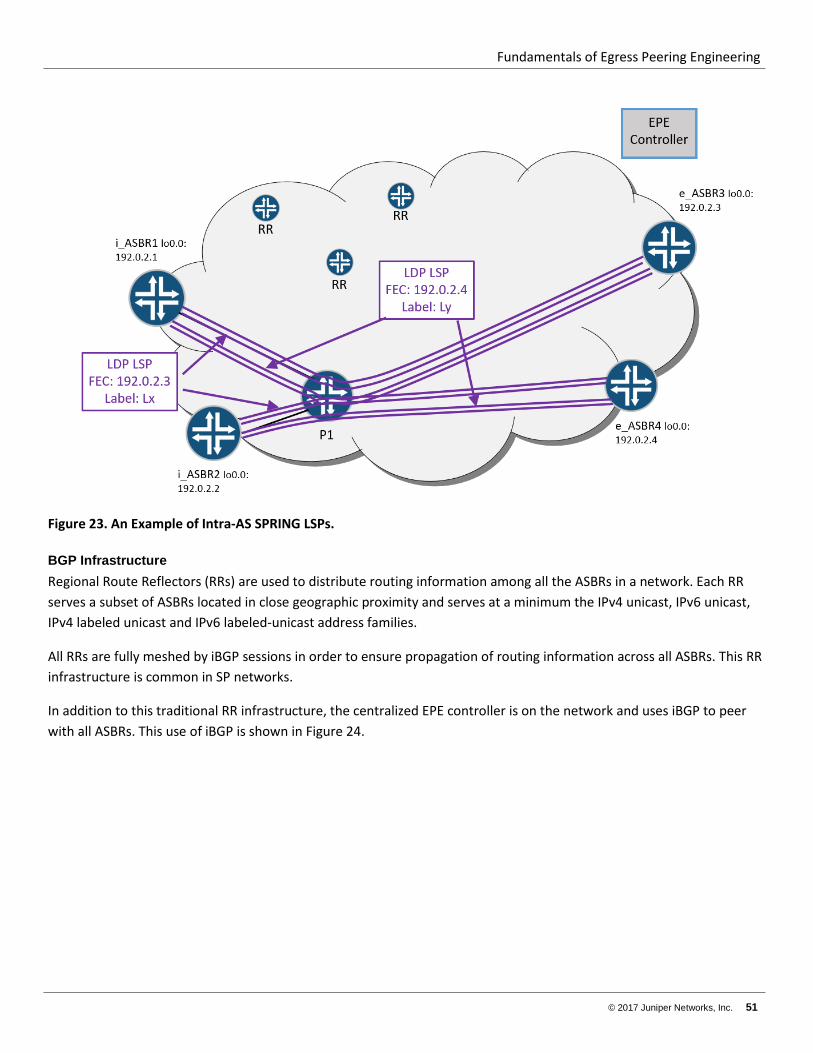
Fundamentals of Egress Peering Engineering
© 2017 Juniper Networks, Inc. 51
Figure 23. An Example of Intra-AS SPRING LSPs.
BGP Infrastructure Regional Route Reflectors (RRs) are used to distribute routing information among all the ASBRs in a network. Each RR serves a subset of ASBRs located in close geographic proximity and serves at a minimum the IPv4 unicast, IPv6 unicast, IPv4 labeled unicast and IPv6 labeled-unicast address families.
All RRs are fully meshed by iBGP sessions in order to ensure propagation of routing information across all ASBRs. This RR infrastructure is common in SP networks.
In addition to this traditional RR infrastructure, the centralized EPE controller is on the network and uses iBGP to peer with all ASBRs. This use of iBGP is shown in Figure 24.
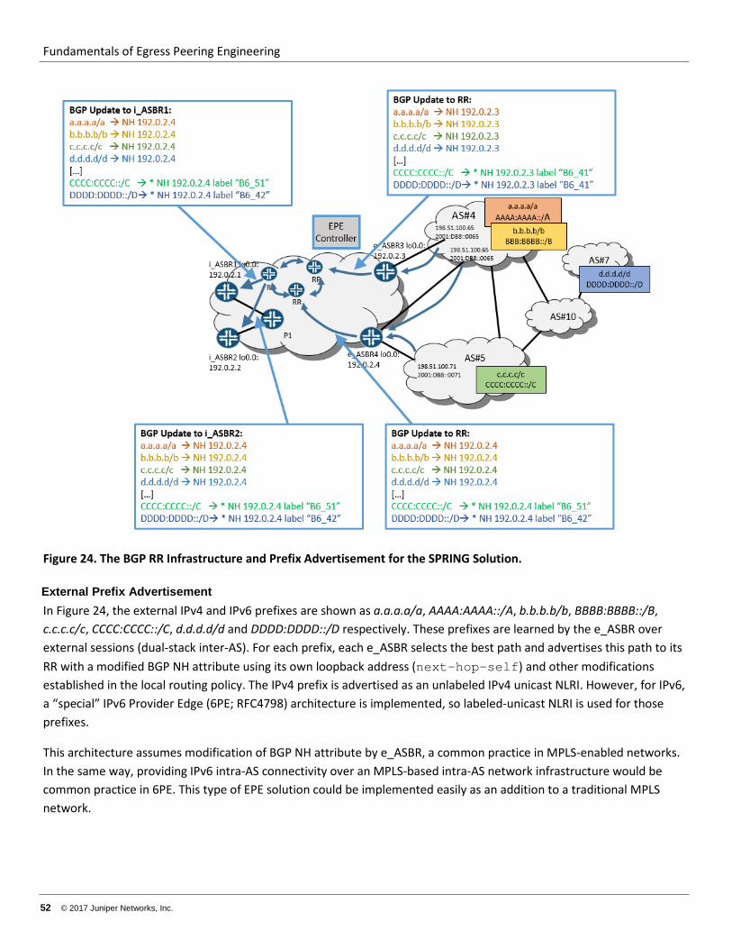
Fundamentals of Egress Peering Engineering
52 © 2017 Juniper Networks, Inc.
Figure 24. The BGP RR Infrastructure and Prefix Advertisement for the SPRING Solution.
External Prefix Advertisement In Figure 24, the external IPv4 and IPv6 prefixes are shown as a.a.a.a/a, AAAA:AAAA::/A, b.b.b.b/b, BBBB:BBBB::/B, c.c.c.c/c, CCCC:CCCC::/C, d.d.d.d/d and DDDD:DDDD::/D respectively. These prefixes are learned by the e_ASBR over external sessions (dual-stack inter-AS). For each prefix, each e_ASBR selects the best path and advertises this path to its RR with a modified BGP NH attribute using its own loopback address (next-hop-self) and other modifications established in the local routing policy. The IPv4 prefix is advertised as an unlabeled IPv4 unicast NLRI. However, for IPv6, a “special” IPv6 Provider Edge (6PE; RFC4798) architecture is implemented, so labeled-unicast NLRI is used for those prefixes.
This architecture assumes modification of BGP NH attribute by e_ASBR, a common practice in MPLS-enabled networks. In the same way, providing IPv6 intra-AS connectivity over an MPLS-based intra-AS network infrastructure would be common practice in 6PE. This type of EPE solution could be implemented easily as an addition to a traditional MPLS network.
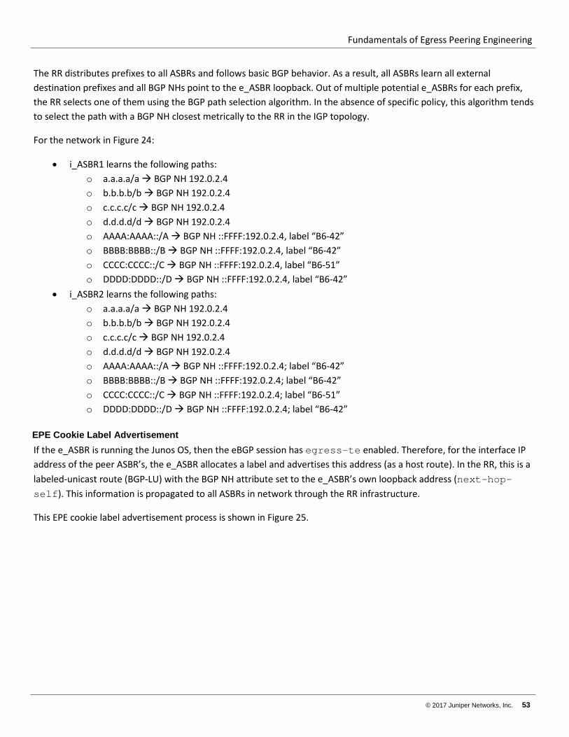
Fundamentals of Egress Peering Engineering
© 2017 Juniper Networks, Inc. 53
The RR distributes prefixes to all ASBRs and follows basic BGP behavior. As a result, all ASBRs learn all external destination prefixes and all BGP NHs point to the e_ASBR loopback. Out of multiple potential e_ASBRs for each prefix, the RR selects one of them using the BGP path selection algorithm. In the absence of specific policy, this algorithm tends to select the path with a BGP NH closest metrically to the RR in the IGP topology.
For the network in Figure 24:
• i_ASBR1 learns the following paths: o a.a.a.a/a BGP NH 192.0.2.4 o b.b.b.b/b BGP NH 192.0.2.4 o c.c.c.c/c BGP NH 192.0.2.4 o d.d.d.d/d BGP NH 192.0.2.4 o AAAA:AAAA::/A BGP NH ::FFFF:192.0.2.4, label “B6-42” o BBBB:BBBB::/B BGP NH ::FFFF:192.0.2.4, label “B6-42” o CCCC:CCCC::/C BGP NH ::FFFF:192.0.2.4, label “B6-51” o DDDD:DDDD::/D BGP NH ::FFFF:192.0.2.4, label “B6-42”
• i_ASBR2 learns the following paths: o a.a.a.a/a BGP NH 192.0.2.4 o b.b.b.b/b BGP NH 192.0.2.4 o c.c.c.c/c BGP NH 192.0.2.4 o d.d.d.d/d BGP NH 192.0.2.4 o AAAA:AAAA::/A BGP NH ::FFFF:192.0.2.4; label “B6-42” o BBBB:BBBB::/B BGP NH ::FFFF:192.0.2.4; label “B6-42” o CCCC:CCCC::/C BGP NH ::FFFF:192.0.2.4; label “B6-51” o DDDD:DDDD::/D BGP NH ::FFFF:192.0.2.4; label “B6-42”
EPE Cookie Label Advertisement If the e_ASBR is running the Junos OS, then the eBGP session has egress-te enabled. Therefore, for the interface IP address of the peer ASBR’s, the e_ASBR allocates a label and advertises this address (as a host route). In the RR, this is a labeled-unicast route (BGP-LU) with the BGP NH attribute set to the e_ASBR’s own loopback address (next-hop-self). This information is propagated to all ASBRs in network through the RR infrastructure.
This EPE cookie label advertisement process is shown in Figure 25.
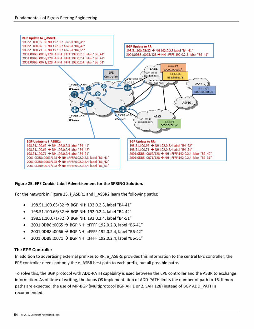
Fundamentals of Egress Peering Engineering
54 © 2017 Juniper Networks, Inc.
Figure 25. EPE Cookie Label Advertisement for the SPRING Solution.
For the network in Figure 25, i_ASBR1 and i_ASBR2 learn the following paths:
• 198.51.100.65/32 BGP NH: 192.0.2.3, label “B4-41” • 198.51.100.66/32 BGP NH: 192.0.2.4, label “B4-42” • 198.51.100.71/32 BGP NH: 192.0.2.4, label “B4-51” • 2001:0DB8::0065 BGP NH: ::FFFF:192.0.2.3, label “B6-41” • 2001:0DB8::0066 BGP NH: ::FFFF:192.0.2.4, label “B6-42” • 2001:0DB8::0071 BGP NH: ::FFFF:192.0.2.4, label “B6-51”
The EPE Controller In addition to advertising external prefixes to RR, e_ASBRs provides this information to the central EPE controller, the EPE controller needs not only the e_ASBR best path to each prefix, but all possible paths.
To solve this, the BGP protocol with ADD-PATH capability is used between the EPE controller and the ASBR to exchange information. As of time of writing, the Junos OS implementation of ADD-PATH limits the number of path to 16. If more paths are expected, the use of MP-BGP (Multiprotocol BGP AFI 1 or 2, SAFI 128) instead of BGP ADD_PATH is recommended.
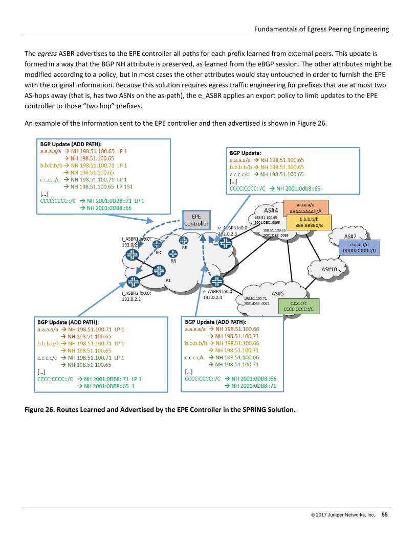
Fundamentals of Egress Peering Engineering
© 2017 Juniper Networks, Inc. 55
The egress ASBR advertises to the EPE controller all paths for each prefix learned from external peers. This update is formed in a way that the BGP NH attribute is preserved, as learned from the eBGP session. The other attributes might be modified according to a policy, but in most cases the other attributes would stay untouched in order to furnish the EPE with the original information. Because this solution requires egress traffic engineering for prefixes that are at most two AS-hops away (that is, has two ASNs on the as-path), the e_ASBR applies an export policy to limit updates to the EPE controller to those “two hop” prefixes.
An example of the information sent to the EPE controller and then advertised is shown in Figure 26.
Figure 26. Routes Learned and Advertised by the EPE Controller in the SPRING Solution.
Fundamentals of Egress Peering Engineering
56 © 2017 Juniper Networks, Inc.
For the network in Figure 26, the EPE controller receives following paths:
• From e_ASBR1: o a.a.a.a/a BGP NH 198.51.100.65 o b.b.b.b/b BGP NH 198.51.100.65 o c.c.c.c/c BGP NH 198.51.100.65 o AAAA:AAAA::/A BGP NH 2001:0DB8::0065 o BBBB:BBBB::/B BGP NH 2001:0DB8::0065 o CCCC:CCCC::/C BGP NH 2001:0DB8::0065
• From e_ASBR2: o a.a.a.a/a BGP NH 198.51.100.66 o a.a.a.a/a BGP NH 198.51.100.71 o b.b.b.b/b BGP NH 198.51.100.66 o b.b.b.b/b BGP NH 198.51.100.71 o c.c.c.c/c BGP NH 198.51.100.66 o c.c.c.c/c BGP NH 198.51.100.71 o AAAA:AAAA::/A BGP NH 2001:0DB8::0066 o AAAA:AAAA::/A BGP NH 2001:0DB8::0071 o BBBB:BBBB::/B BGP NH 2001:0DB8::0066 o BBBB:BBBB::/B BGP NH 2001:0DB8::0071 o CCCC:CCCC::/C BGP NH 2001:0DB8::0066 o CCCC:CCCC::/C BGP NH 2001:0DB8::0071
For each [ i_ASBR, destination prefix] pair, the EPE controller selects the path out of all paths available (that is, those learned from the e_ASBRs). The actual algorithm depends on the EPE logic and is beyond the scope of this document and not considered further. However, it is worth noting that, from the perspective of the ASBR, the EPE appears to be another RR, but one that executes a very flexible and dynamic policies engine.
The ingress ASBR learns the single best path for each external prefix from the EPE controller. This update is formed in a way so that the BGP NH attribute is preserved as learned from the eBGP session. Optionally, thanks to the BGP ADD_PATH feature, the EPE controller can also provide a second path in order to help in fast convergence. Also, the i_ASBR must prefer a path received from the EPE controller over a path learned from an RR. If the i_ASBR runs the Junos OS, then the ingress policy on the session with the EPE Controller sets the protocol preference for the path received from EPE controller to value lower then default BGP protocol preference (for example, lower than 160). This forces the EPE path to be selected as best, regardless of the BGP attribute values on the other path.
It is also a good practice for the EPE controller to set the local preference attribute for the prefix to a high value. For example, the best EPE path gets a local preference of 155 and the backup EPE path gets a local preference of 151. This serves the purpose of differentiating the best and the backup EPE path, and also provides an additional mechanism for the i_ASBR to prefer the EPE path over the path from an RR (assuming the default local preferences).
For the network in Figure 26, the i_ASBRs receive the following paths from EPE controller:
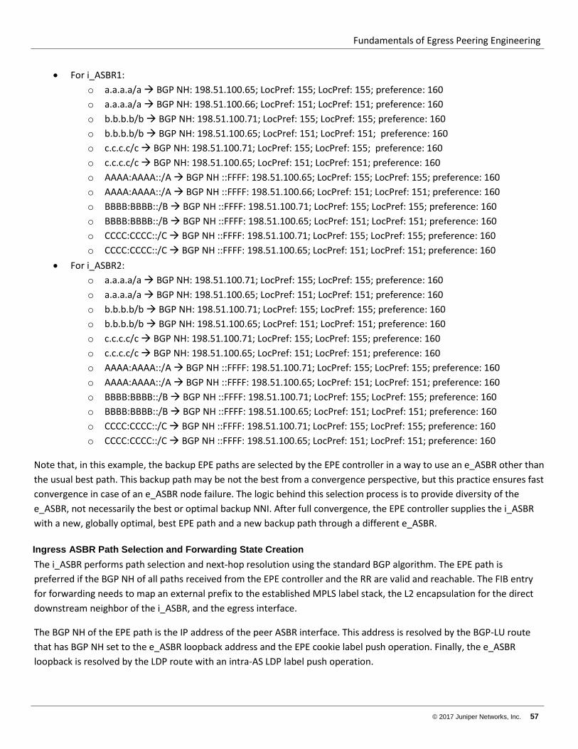
Fundamentals of Egress Peering Engineering
© 2017 Juniper Networks, Inc. 57
• For i_ASBR1: o a.a.a.a/a BGP NH: 198.51.100.65; LocPref: 155; LocPref: 155; preference: 160 o a.a.a.a/a BGP NH: 198.51.100.66; LocPref: 151; LocPref: 151; preference: 160 o b.b.b.b/b BGP NH: 198.51.100.71; LocPref: 155; LocPref: 155; preference: 160 o b.b.b.b/b BGP NH: 198.51.100.65; LocPref: 151; LocPref: 151; preference: 160 o c.c.c.c/c BGP NH: 198.51.100.71; LocPref: 155; LocPref: 155; preference: 160 o c.c.c.c/c BGP NH: 198.51.100.65; LocPref: 151; LocPref: 151; preference: 160 o AAAA:AAAA::/A BGP NH ::FFFF: 198.51.100.65; LocPref: 155; LocPref: 155; preference: 160 o AAAA:AAAA::/A BGP NH ::FFFF: 198.51.100.66; LocPref: 151; LocPref: 151; preference: 160 o BBBB:BBBB::/B BGP NH ::FFFF: 198.51.100.71; LocPref: 155; LocPref: 155; preference: 160 o BBBB:BBBB::/B BGP NH ::FFFF: 198.51.100.65; LocPref: 151; LocPref: 151; preference: 160 o CCCC:CCCC::/C BGP NH ::FFFF: 198.51.100.71; LocPref: 155; LocPref: 155; preference: 160 o CCCC:CCCC::/C BGP NH ::FFFF: 198.51.100.65; LocPref: 151; LocPref: 151; preference: 160
• For i_ASBR2: o a.a.a.a/a BGP NH: 198.51.100.71; LocPref: 155; LocPref: 155; preference: 160 o a.a.a.a/a BGP NH: 198.51.100.65; LocPref: 151; LocPref: 151; preference: 160 o b.b.b.b/b BGP NH: 198.51.100.71; LocPref: 155; LocPref: 155; preference: 160 o b.b.b.b/b BGP NH: 198.51.100.65; LocPref: 151; LocPref: 151; preference: 160 o c.c.c.c/c BGP NH: 198.51.100.71; LocPref: 155; LocPref: 155; preference: 160 o c.c.c.c/c BGP NH: 198.51.100.65; LocPref: 151; LocPref: 151; preference: 160 o AAAA:AAAA::/A BGP NH ::FFFF: 198.51.100.71; LocPref: 155; LocPref: 155; preference: 160 o AAAA:AAAA::/A BGP NH ::FFFF: 198.51.100.65; LocPref: 151; LocPref: 151; preference: 160 o BBBB:BBBB::/B BGP NH ::FFFF: 198.51.100.71; LocPref: 155; LocPref: 155; preference: 160 o BBBB:BBBB::/B BGP NH ::FFFF: 198.51.100.65; LocPref: 151; LocPref: 151; preference: 160 o CCCC:CCCC::/C BGP NH ::FFFF: 198.51.100.71; LocPref: 155; LocPref: 155; preference: 160 o CCCC:CCCC::/C BGP NH ::FFFF: 198.51.100.65; LocPref: 151; LocPref: 151; preference: 160
Note that, in this example, the backup EPE paths are selected by the EPE controller in a way to use an e_ASBR other than the usual best path. This backup path may be not the best from a convergence perspective, but this practice ensures fast convergence in case of an e_ASBR node failure. The logic behind this selection process is to provide diversity of the e_ASBR, not necessarily the best or optimal backup NNI. After full convergence, the EPE controller supplies the i_ASBR with a new, globally optimal, best EPE path and a new backup path through a different e_ASBR.
Ingress ASBR Path Selection and Forwarding State Creation The i_ASBR performs path selection and next-hop resolution using the standard BGP algorithm. The EPE path is preferred if the BGP NH of all paths received from the EPE controller and the RR are valid and reachable. The FIB entry for forwarding needs to map an external prefix to the established MPLS label stack, the L2 encapsulation for the direct downstream neighbor of the i_ASBR, and the egress interface.
The BGP NH of the EPE path is the IP address of the peer ASBR interface. This address is resolved by the BGP-LU route that has BGP NH set to the e_ASBR loopback address and the EPE cookie label push operation. Finally, the e_ASBR loopback is resolved by the LDP route with an intra-AS LDP label push operation.
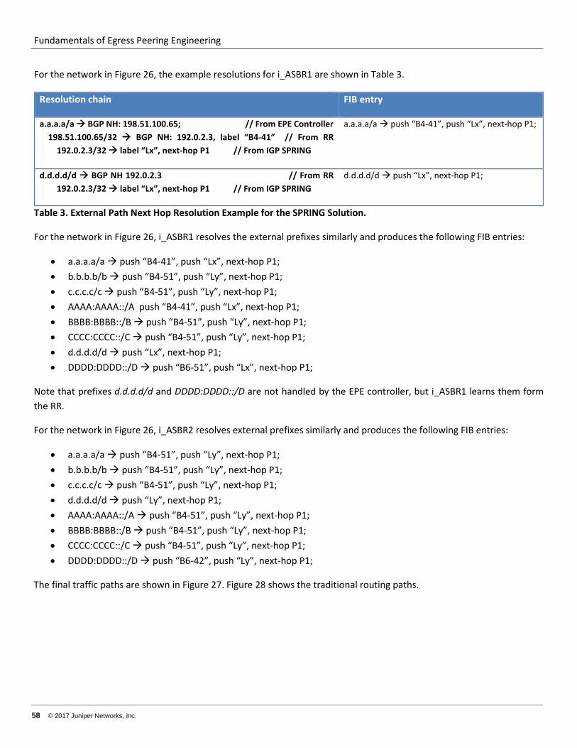
Fundamentals of Egress Peering Engineering
58 © 2017 Juniper Networks, Inc.
For the network in Figure 26, the example resolutions for i_ASBR1 are shown in Table 3.
Resolution chain FIB entry
a.a.a.a/a BGP NH: 198.51.100.65; // From EPE Controller 198.51.100.65/32 BGP NH: 192.0.2.3, label “B4-41” // From RR 192.0.2.3/32 label “Lx”, next-hop P1 // From IGP SPRING
a.a.a.a/a push “B4-41”, push “Lx”, next-hop P1;
d.d.d.d/d BGP NH 192.0.2.3 // From RR 192.0.2.3/32 label “Lx”, next-hop P1 // From IGP SPRING
d.d.d.d/d push “Lx”, next-hop P1;
Table 3. External Path Next Hop Resolution Example for the SPRING Solution.
For the network in Figure 26, i_ASBR1 resolves the external prefixes similarly and produces the following FIB entries:
• a.a.a.a/a push “B4-41”, push “Lx”, next-hop P1; • b.b.b.b/b push “B4-51”, push “Ly”, next-hop P1; • c.c.c.c/c push “B4-51”, push “Ly”, next-hop P1; • AAAA:AAAA::/A push “B4-41”, push “Lx”, next-hop P1; • BBBB:BBBB::/B push “B4-51”, push “Ly”, next-hop P1; • CCCC:CCCC::/C push “B4-51”, push “Ly”, next-hop P1; • d.d.d.d/d push “Lx”, next-hop P1; • DDDD:DDDD::/D push “B6-51”, push “Lx”, next-hop P1;
Note that prefixes d.d.d.d/d and DDDD:DDDD::/D are not handled by the EPE controller, but i_ASBR1 learns them form the RR.
For the network in Figure 26, i_ASBR2 resolves external prefixes similarly and produces the following FIB entries:
• a.a.a.a/a push “B4-51”, push “Ly”, next-hop P1; • b.b.b.b/b push “B4-51”, push “Ly”, next-hop P1; • c.c.c.c/c push “B4-51”, push “Ly”, next-hop P1; • d.d.d.d/d push “Ly”, next-hop P1; • AAAA:AAAA::/A push “B4-51”, push “Ly”, next-hop P1; • BBBB:BBBB::/B push “B4-51”, push “Ly”, next-hop P1; • CCCC:CCCC::/C push “B4-51”, push “Ly”, next-hop P1; • DDDD:DDDD::/D push “B6-42”, push “Ly”, next-hop P1;
The final traffic paths are shown in Figure 27. Figure 28 shows the traditional routing paths.
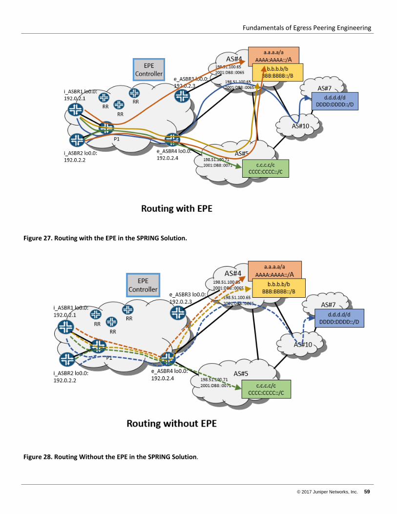
Fundamentals of Egress Peering Engineering
© 2017 Juniper Networks, Inc. 59
Figure 27. Routing with the EPE in the SPRING Solution.
Figure 28. Routing Without the EPE in the SPRING Solution.
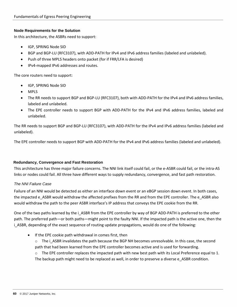
Fundamentals of Egress Peering Engineering
60 © 2017 Juniper Networks, Inc.
Node Requirements for the Solution In this architecture, the ASBRs need to support:
• IGP, SPRING Node SID • BGP and BGP-LU (RFC3107), with ADD-PATH for IPv4 and IPv6 address families (labeled and unlabeled). • Push of three MPLS headers onto packet (for if FRR/LFA is desired) • IPv4-mapped IPv6 addresses and routes.
The core routers need to support:
• IGP, SPRING Node SID • MPLS • The RR needs to support BGP and BGP-LU (RFC3107), both with ADD-PATH for the IPv4 and IPv6 address families,
labeled and unlabeled. • The EPE controller needs to support BGP with ADD-PATH for the IPv4 and IPv6 address families, labeled and
unlabeled.
The RR needs to support BGP and BGP-LU (RFC3107), with ADD-PATH for the IPv4 and IPv6 address families (labeled and unlabeled).
The EPE controller needs to support BGP with ADD-PATH for the IPv4 and IPv6 address families (labeled and unlabeled).
Redundancy, Convergence and Fast Restoration This architecture has three major failure concerns. The NNI link itself could fail, or the e-ASBR could fail, or the intra-AS links or nodes could fail. All three have different ways to supply redundancy, convergence, and fast path restoration.
The NNI Failure Case
Failure of an NNI would be detected as either an interface down event or an eBGP session down event. In both cases, the impacted e_ASBR would withdraw the affected prefixes from the RR and from the EPE controller. The e_ASBR also would withdraw the path to the peer ASBR interface’s IP address that conveys the EPE cookie from the RR.
One of the two paths learned by the i_ASBR from the EPE controller by way of BGP ADD-PATH is preferred to the other path. The preferred path—or both paths—might point to the faulty NNI. If the impacted path is the active one, then the i_ASBR, depending of the exact sequence of routing update propagations, would do one of the following:
• If the EPE cookie path withdrawal in comes first, then o The i_ASBR invalidates the path because the BGP NH becomes unresolvable. In this case, the second path that had been learned from the EPE controller becomes active and is used for forwarding. o The EPE controller replaces the impacted path with new best path with its Local Preference equal to 1. The backup path might need to be replaced as well, in order to preserve a diverse e_ASBR condition.
Fundamentals of Egress Peering Engineering
© 2017 Juniper Networks, Inc. 61
• If the BGP prefix path withdrawal comes first, then the EPE controller withdraws the invalid path and replaces it with a new best path. As before, the backup path might need to be replaced as well to preserve a diverse e_ASBR condition.
This procedure requires failure propagation over the network from the e_ASBR all the way to the i_ASBR. This action might take tens or even hundreds of milliseconds. During this interval, traffic might be lost. In order to reduce time of traffic loss, local protection at point of failure is needed. In the Junos OS, the egress-te feature enables this protection. See http://www.juniper.net/techpubs/en_US/junos16.1/topics/task/configuration/configuring-egress-te-using-bgp-lu.html for more information.
If an NNI fails, the adjacent e_ASBR sends traffic to one of the following:
• Another local NNI. • Another NNI on another e_ASBR. This is done by switching traffic from an LDP LSP tunnel to a backup e_ASBR
and pushing the EPE cookie label (learned from an RR) that points to this other NNI.
This technique reduces traffic loss time to the tens of milliseconds.
The e_ASBR Failure Case
Failure of an e_ASBR uses a network convergence process similar to an NNI failure. The only difference is that, in addition to BGP routes withdrawal, the IGP route leading to the e_ASBR loopback address and its associated LSP are also removed. Because an IGP is usually faster than BGP to converge, removal of the e_ASBR loopback address and LSP is the initial event seen by i_ASBR. This event deactivates all of the BGP paths that use this address. It also deactivates the BGP NH. All the EPE cookie routes learned from this e_ASBR and all external prefixes learned from the RR that has this BGP NH. Recursively, all routes from the EPE controller resolved by the inactive EPE cookie routs are deactivated.
Because an EPE controller provides two diverse routes to reach NNIs for each prefix, an i_ASBR locally switches traffic to the backup NNI.
Finally, when the EPE controller calculates a new “best exit” NNI and a new different backup NNI, the controller updates i_ASBR with this information, which then replaces the two old BGP routes.
The Inta_AS Links or Internal Node Failures
Failure of intra-AS links of internal nodes are primarily handled by simple IGP convergence. Optionally, this process could be augmented by BFD in order to speed up detection of some types of failures. For fast restoration, the network could use LFA or R-LFA, augmented by an explicit or dynamic (that is, TI-FRR) backup LSP.
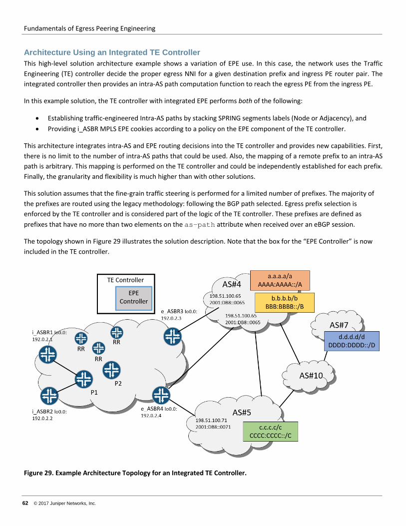
Fundamentals of Egress Peering Engineering
62 © 2017 Juniper Networks, Inc.
Architecture Using an Integrated TE Controller This high-level solution architecture example shows a variation of EPE use. In this case, the network uses the Traffic Engineering (TE) controller decide the proper egress NNI for a given destination prefix and ingress PE router pair. The integrated controller then provides an intra-AS path computation function to reach the egress PE from the ingress PE.
In this example solution, the TE controller with integrated EPE performs both of the following:
• Establishing traffic-engineered Intra-AS paths by stacking SPRING segments labels (Node or Adjacency), and • Providing i_ASBR MPLS EPE cookies according to a policy on the EPE component of the TE controller.
This architecture integrates intra-AS and EPE routing decisions into the TE controller and provides new capabilities. First, there is no limit to the number of intra-AS paths that could be used. Also, the mapping of a remote prefix to an intra-AS path is arbitrary. This mapping is performed on the TE controller and could be independently established for each prefix. Finally, the granularity and flexibility is much higher than with other solutions.
This solution assumes that the fine-grain traffic steering is performed for a limited number of prefixes. The majority of the prefixes are routed using the legacy methodology: following the BGP path selected. Egress prefix selection is enforced by the TE controller and is considered part of the logic of the TE controller. These prefixes are defined as prefixes that have no more than two elements on the as-path attribute when received over an eBGP session.
The topology shown in Figure 29 illustrates the solution description. Note that the box for the “EPE Controller” is now included in the TE controller.
Figure 29. Example Architecture Topology for an Integrated TE Controller.
Fundamentals of Egress Peering Engineering
© 2017 Juniper Networks, Inc. 63
Intra-AS Routing and LSP Signaling and Segment Labels. The network IGP could be IS-IS or OSPF. The IGP carries routing information about AS-internal links and router loopbacks, as well as the MPLS labels associated with them—the Node Segment and Adjacency Segment labels. But the IGP does not carry prefixes associated with the NNI links. This is a simple form of SPRING and expected to be a common architecture in early SPRING deployment in service provider networks.
In this solution, two types of LSPs are used:
• Shortest path LSPs—The MPLS LSPs are established by extracting forwarding states from SPRING IGP information. This solution uses Node Segment LSPs only, so the LSPs follow IGP shortest paths to the destination. As a result, all ASBRs have an LSP available that leads to all other ASBRs. The FEC for this LSP is the IP address of the target ASBR’s loopback interface. These LSPs are built by routers and used in this solution for intra-AS transport of traffic for prefixes that are not of concern to the EPE computation.
• Traffic Engineered stack of segments (labels)—The stack is defined for each [i_ASBR, prefix] pair by the TE controller based on segment label information (the SPRING Segment Routing Global Block [SRGB] and adj-SID), IGP traffic-engineering database (TED) topology, and other factors (for example, traffic volume per [i_ASBR, prefix] pair, latency requirements, desired protection level, and so on). Please note that the TE controller either participates in the IGP flooding domain or a BGP-LS session provides the TE controller with the necessary information. This information includes topology, adj-SID labels, SRGB, Segment Routing Label Group (SRLG), link bandwidth, and so on, for all nodes and links).
Bidirectional Forwarding Detection (BFD) and Remote Loop Free Alternative (R-LFA) techniques can be used to reduce failure detection and traffic restoration time when internal links or transit nodes fail. Note that SPRING allows for the augmentation of the topology for R-LFA by using TE tunnels established by stacking labels (SPRING TE). This stacking results in 100% coverage for any topology. The EPE solution discussed here can benefit from this option if it is supported by the network devices.
In Figure 30, i_ASBR1 and i_ASBR2 have a shortest path LSP toward FEC 192.0.2.3/32 (the loopback address of e_ASBR3) and another LSP toward FEC 192.0.2.4/32 (the loopback address of e_ASBR4). The backup LSPs resulting from R-LFA are not shown in the figure because they are irrelevant for any explanation of EPE function. All i_ASBRs install the following routes in their IPv4 labeled unicast RIB and IPv6 labeled unicast RIB (inet.3 and inet6.3):
192.0.2.3/32 push label “Lx”, next-hop P1 192.0.2.4/32 push label “Ly”, next-hop P1 ::FFFF:192.0.2.3/32 push label “Lx”, next-hop P1 ::FFFF:192.0.2.4/32 push label “Ly”, next-hop P1
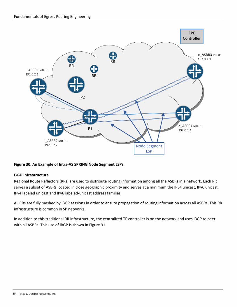
Fundamentals of Egress Peering Engineering
64 © 2017 Juniper Networks, Inc.
Figure 30. An Example of Intra-AS SPRING Node Segment LSPs.
BGP infrastructure Regional Route Reflectors (RRs) are used to distribute routing information among all the ASBRs in a network. Each RR serves a subset of ASBRs located in close geographic proximity and serves at a minimum the IPv4 unicast, IPv6 unicast, IPv4 labeled unicast and IPv6 labeled-unicast address families.
All RRs are fully meshed by iBGP sessions in order to ensure propagation of routing information across all ASBRs. This RR infrastructure is common in SP networks.
In addition to this traditional RR infrastructure, the centralized TE controller is on the network and uses iBGP to peer with all ASBRs. This use of iBGP is shown in Figure 31.
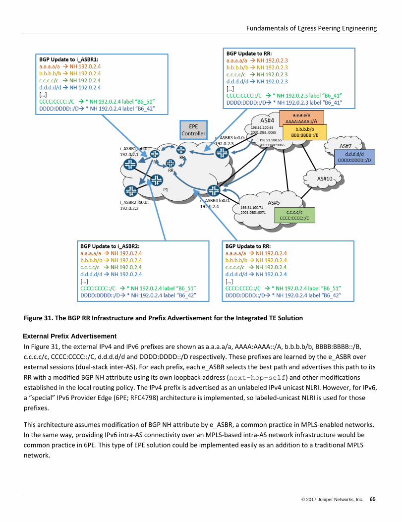
Fundamentals of Egress Peering Engineering
© 2017 Juniper Networks, Inc. 65
Figure 31. The BGP RR Infrastructure and Prefix Advertisement for the Integrated TE Solution
External Prefix Advertisement In Figure 31, the external IPv4 and IPv6 prefixes are shown as a.a.a.a/a, AAAA:AAAA::/A, b.b.b.b/b, BBBB:BBBB::/B, c.c.c.c/c, CCCC:CCCC::/C, d.d.d.d/d and DDDD:DDDD::/D respectively. These prefixes are learned by the e_ASBR over external sessions (dual-stack inter-AS). For each prefix, each e_ASBR selects the best path and advertises this path to its RR with a modified BGP NH attribute using its own loopback address (next-hop-self) and other modifications established in the local routing policy. The IPv4 prefix is advertised as an unlabeled IPv4 unicast NLRI. However, for IPv6, a “special” IPv6 Provider Edge (6PE; RFC4798) architecture is implemented, so labeled-unicast NLRI is used for those prefixes.
This architecture assumes modification of BGP NH attribute by e_ASBR, a common practice in MPLS-enabled networks. In the same way, providing IPv6 intra-AS connectivity over an MPLS-based intra-AS network infrastructure would be common practice in 6PE. This type of EPE solution could be implemented easily as an addition to a traditional MPLS network.
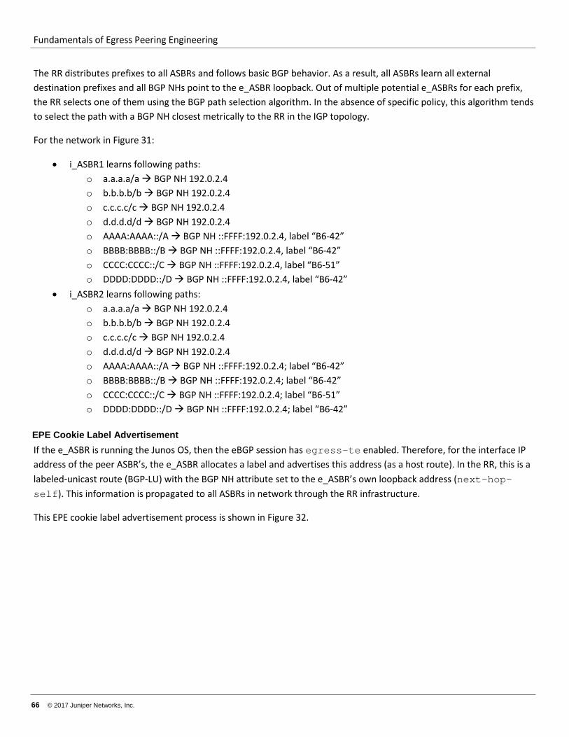
Fundamentals of Egress Peering Engineering
66 © 2017 Juniper Networks, Inc.
The RR distributes prefixes to all ASBRs and follows basic BGP behavior. As a result, all ASBRs learn all external destination prefixes and all BGP NHs point to the e_ASBR loopback. Out of multiple potential e_ASBRs for each prefix, the RR selects one of them using the BGP path selection algorithm. In the absence of specific policy, this algorithm tends to select the path with a BGP NH closest metrically to the RR in the IGP topology.
For the network in Figure 31:
• i_ASBR1 learns following paths: o a.a.a.a/a BGP NH 192.0.2.4 o b.b.b.b/b BGP NH 192.0.2.4 o c.c.c.c/c BGP NH 192.0.2.4 o d.d.d.d/d BGP NH 192.0.2.4 o AAAA:AAAA::/A BGP NH ::FFFF:192.0.2.4, label “B6-42” o BBBB:BBBB::/B BGP NH ::FFFF:192.0.2.4, label “B6-42” o CCCC:CCCC::/C BGP NH ::FFFF:192.0.2.4, label “B6-51” o DDDD:DDDD::/D BGP NH ::FFFF:192.0.2.4, label “B6-42”
• i_ASBR2 learns following paths: o a.a.a.a/a BGP NH 192.0.2.4 o b.b.b.b/b BGP NH 192.0.2.4 o c.c.c.c/c BGP NH 192.0.2.4 o d.d.d.d/d BGP NH 192.0.2.4 o AAAA:AAAA::/A BGP NH ::FFFF:192.0.2.4; label “B6-42” o BBBB:BBBB::/B BGP NH ::FFFF:192.0.2.4; label “B6-42” o CCCC:CCCC::/C BGP NH ::FFFF:192.0.2.4; label “B6-51” o DDDD:DDDD::/D BGP NH ::FFFF:192.0.2.4; label “B6-42”
EPE Cookie Label Advertisement If the e_ASBR is running the Junos OS, then the eBGP session has egress-te enabled. Therefore, for the interface IP address of the peer ASBR’s, the e_ASBR allocates a label and advertises this address (as a host route). In the RR, this is a labeled-unicast route (BGP-LU) with the BGP NH attribute set to the e_ASBR’s own loopback address (next-hop-self). This information is propagated to all ASBRs in network through the RR infrastructure.
This EPE cookie label advertisement process is shown in Figure 32.
Fundamentals of Egress Peering Engineering
© 2017 Juniper Networks, Inc. 67
Figure 32. EPE Cookie Label Advertisement for the Inclusive EPE Solution.
For the network in Figure 32, the TE Controller learns following paths:
• 198.51.100.65/32 BGP NH: 192.0.2.3, label “B4-41” • 198.51.100.66/32 BGP NH: 192.0.2.4, label “B4-42” • 198.51.100.71/32 BGP NH: 192.0.2.4, label “B4-51” • 2001:0DB8::0065 BGP NH: ::FFFF:192.0.2.3, label “B6-41” • 2001:0DB8::0066 BGP NH: ::FFFF:192.0.2.4, label “B6-42” • 2001:0DB8::0071 BGP NH: ::FFFF:192.0.2.4, label “B6-51”
Fundamentals of Egress Peering Engineering
68 © 2017 Juniper Networks, Inc.
SPRING Labels and Topology Learning The TE controller participates in IGP routing (or peers using BGP-LS with some of the routers) and learns:
• Intra-AS network topology, including link costs • TE attributes of links and nodes: SRLG, bandwidth affinity groups, and so on • SPRING labels—At a minimum, the Node Segment and Adjacency Segment. • IP addresses and SIDs
This information is sufficient for the TE controller to apply programmed logic (the details are beyond the scope of this paper) and to calculate the optimal intra-AS path through the topology all the way from an i_ASBR to an e_ASBR and NNI for each remote prefix.
The TE controller In addition to advertising external prefixes to RR, e_ASBRs provides this information to the central TE controller, the TE controller needs not only the e_ASBR best path to each prefix, but all possible paths.
To solve this, the BGP protocol with ADD-PATH capability is used between the TE controller and the ASBR to exchange information. As of time of writing, the Junos OS implementation of ADD-PATH limits the number of path to 16. If more paths are expected, the use of MP-BGP (Multiprotocol BGP AFI 1 or 2, SAFI 128) instead of BGP ADD_PATH is recommended.
The egress ASBR advertises to the TE controller all paths for each prefix learned from external peers. This update is formed in a way that the BGP NH attribute is preserved, as learned from the eBGP session. The other attributes might be modified according to a policy, but in most cases the other attributes would stay untouched in order to furnish the EPE with the original information. Because this solution requires egress traffic engineering for prefixes that are at most two AS-hops away (that is, has two ASNs on the as-path), the e_ASBR applies an export policy to limit updates to the EPE controller to those “two hop” prefixes.
An example of the information sent to the TE controller and then advertised is shown in Figure 33.
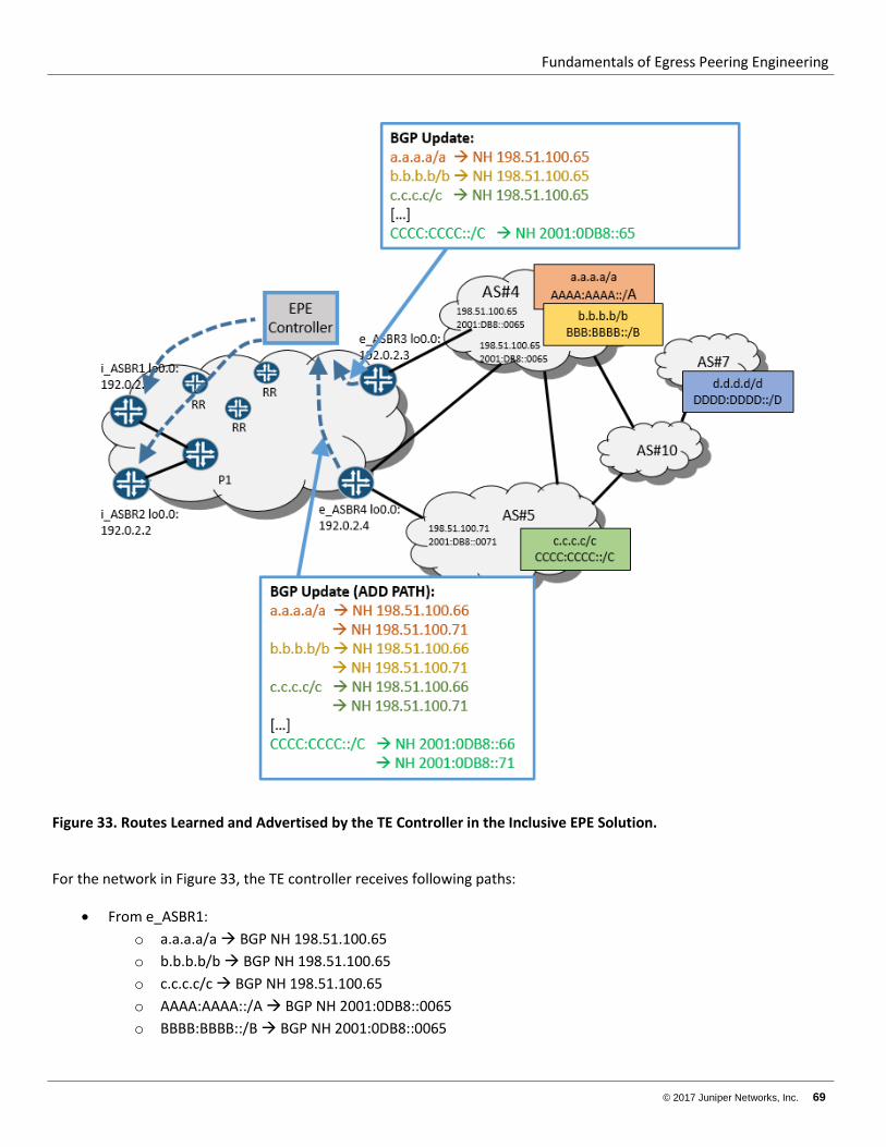
Fundamentals of Egress Peering Engineering
© 2017 Juniper Networks, Inc. 69
Figure 33. Routes Learned and Advertised by the TE Controller in the Inclusive EPE Solution.
For the network in Figure 33, the TE controller receives following paths:
• From e_ASBR1: o a.a.a.a/a BGP NH 198.51.100.65 o b.b.b.b/b BGP NH 198.51.100.65 o c.c.c.c/c BGP NH 198.51.100.65 o AAAA:AAAA::/A BGP NH 2001:0DB8::0065 o BBBB:BBBB::/B BGP NH 2001:0DB8::0065
Fundamentals of Egress Peering Engineering
70 © 2017 Juniper Networks, Inc.
o CCCC:CCCC::/C BGP NH 2001:0DB8::0065 • From e_ASBR2:
o a.a.a.a/a BGP NH 198.51.100.66 o a.a.a.a/a BGP NH 198.51.100.71 o b.b.b.b/b BGP NH 198.51.100.66 o b.b.b.b/b BGP NH 198.51.100.71 o c.c.c.c/c BGP NH 198.51.100.66 o c.c.c.c/c BGP NH 198.51.100.71 o AAAA:AAAA::/A BGP NH 2001:0DB8::0066 o AAAA:AAAA::/A BGP NH 2001:0DB8::0071 o BBBB:BBBB::/B BGP NH 2001:0DB8::0066 o BBBB:BBBB::/B BGP NH 2001:0DB8::0071 o CCCC:CCCC::/C BGP NH 2001:0DB8::0066 o CCCC:CCCC::/C BGP NH 2001:0DB8::0071
The TE Controller performs the following calculations:
1. For each [ i_ASBR, destination prefix] pair, the TE Controller selects the BGP path out of all available paths learned from the e_ASBRs. The actual algorithm depends on business logic and is out of scope of this document. It is worth noting that from the perspective of an ASBR, the EPE appears as an RR that executes a very flexible and dynamic policy engine.
2. For each [ i_ASBR, destination prefix] pair, TE Controller select desired Intra-AS path toward e_ASBR of selected BGP path. The actual algorithm depends on programmed logic and beyond the scope of this document. Based on the information learned from the IGP (or BGP-LS), the TE Controller constructs a stack of segments (labels) that follows the desired intra-AS path and extracts the IP address of an i_ASBR’s direct neighbor interface.
As result, for each [ i_ASBR, destination prefix] pair, the TE controller creates a BGP-LU NLRI for this prefix containing a list of labels. This list is the concatenation of the intra-AS TE stack of segments (path) and the EPE cookie label, located in the innermost position. The next-hop attribute of this NLRI contains the IP address of i_ASBR’s direct downstream neighbor interface. Other attributes may be inherited from the selected path learned from an e_ASBR.
This process is illustrated in Figure 34.
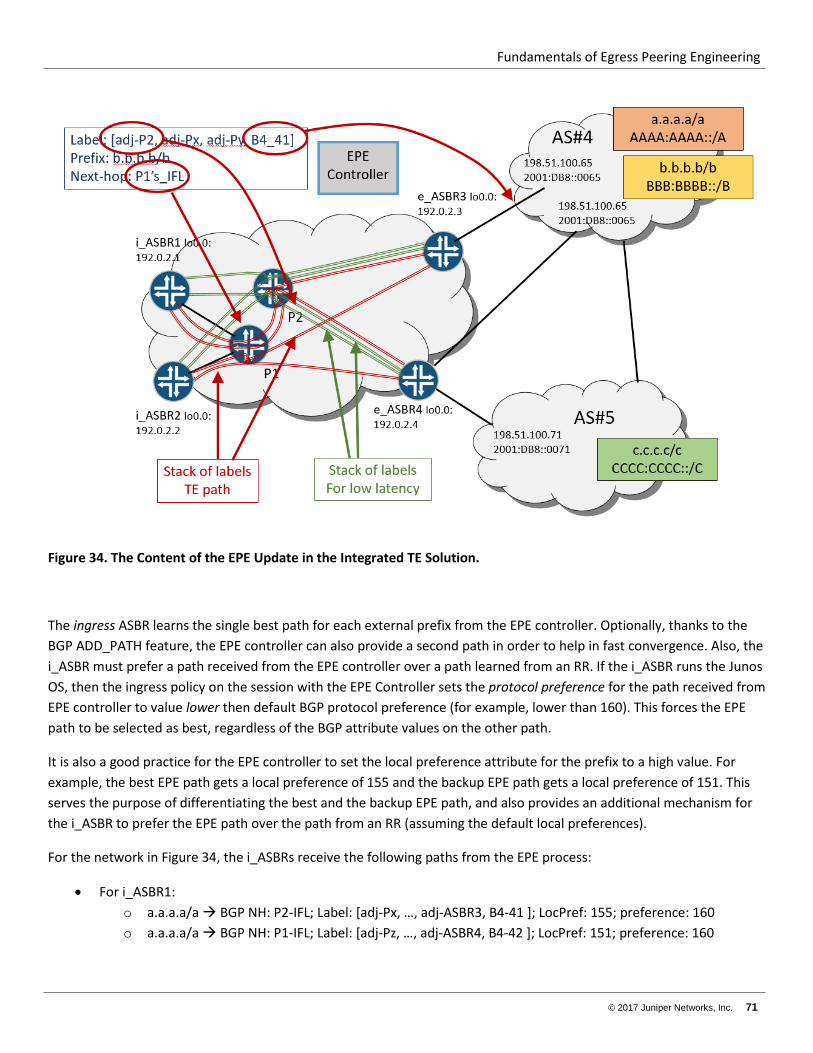
Fundamentals of Egress Peering Engineering
© 2017 Juniper Networks, Inc. 71
Figure 34. The Content of the EPE Update in the Integrated TE Solution.
The ingress ASBR learns the single best path for each external prefix from the EPE controller. Optionally, thanks to the BGP ADD_PATH feature, the EPE controller can also provide a second path in order to help in fast convergence. Also, the i_ASBR must prefer a path received from the EPE controller over a path learned from an RR. If the i_ASBR runs the Junos OS, then the ingress policy on the session with the EPE Controller sets the protocol preference for the path received from EPE controller to value lower then default BGP protocol preference (for example, lower than 160). This forces the EPE path to be selected as best, regardless of the BGP attribute values on the other path.
It is also a good practice for the EPE controller to set the local preference attribute for the prefix to a high value. For example, the best EPE path gets a local preference of 155 and the backup EPE path gets a local preference of 151. This serves the purpose of differentiating the best and the backup EPE path, and also provides an additional mechanism for the i_ASBR to prefer the EPE path over the path from an RR (assuming the default local preferences).
For the network in Figure 34, the i_ASBRs receive the following paths from the EPE process:
• For i_ASBR1: o a.a.a.a/a BGP NH: P2-IFL; Label: [adj-Px, …, adj-ASBR3, B4-41 ]; LocPref: 155; preference: 160 o a.a.a.a/a BGP NH: P1-IFL; Label: [adj-Pz, …, adj-ASBR4, B4-42 ]; LocPref: 151; preference: 160
Fundamentals of Egress Peering Engineering
72 © 2017 Juniper Networks, Inc.
o b.b.b.b/b BGP NH: P1-IFL; Label: [adj-P2, …, adj-ASBR4, B4-51]; LocPref: 155; preference: 160 o b.b.b.b/b BGP NH: P2-IFL; Label: [adj-Pz, …, adj-ASBR3, B4-41]; LocPref: 151; preference: 160 o c.c.c.c/c BGP NH: 192.0.2.4; Label: [B4-51]; LocPref: 155; preference: 160 o c.c.c.c/c BGP NH: 192.0.2.3; Label: [B4-41]; LocPref: 151; preference: 160 o AAAA:AAAA::/A BGP NH P2-IFL; Label: [adj-Px, …, adj-ASBR3, B6-41 ]; LocPref: 155; preference: 160;
LocPref: 1; preference: 160 o AAAA:AAAA::/A BGP NH: P1-IFL; Label: [adj-Pz, …, adj-ASBR4, B6-42 ]; LocPref: 151; preference: 160 o BBBB:BBBB::/B BGP NH: P1-IFL; Label: [adj-P2, …, adj-ASBR4, B4-51]; LocPref: 155; preference: 160 o BBBB:BBBB::/B BGP NH: P2-IFL; Label: [adj-Pz, …, adj-ASBR3, B4-41]; LocPref: 151; preference: 160 o CCCC:CCCC::/C BGP NH ::FFFF: 192.0.2.4; Label: [B4-51]; LocPref: 155; preference: 160 o CCCC:CCCC::/C BGP NH ::FFFF: 192.0.2.3; Label: [B4-41]; LocPref: 151; preference: 160
• For i_ASBR2: o a.a.a.a/a BGP NH: 192.0.2.4; Label: [B4-51]; LocPref: 155; preference: 160 o a.a.a.a/a BGP NH: 192.0.2.3; Label: [B4-41]; LocPref: 151; preference: 160 o b.b.b.b/b BGP NH: P1-IFL; label: [ …, adj-ASBR4, B4-51]; LocPref: 155; preference: 160 o b.b.b.b/b BGP NH: P2-IFL; label: [ …, adj-ASBR3, B4-41]; LocPref: 151; preference: 160 o c.c.c.c/c BGP NH: P2-IFL; label: [ …, adj-ASBR4, B4-51]; LocPref: 155; preference: 160 o c.c.c.c/c BGP NH: P1-IFL; label: [ …, adj-ASBR3, B4-41]; LocPref: 151; preference: 160 o AAAA:AAAA::/A BGP NH ::FFFF: 192.0.2.4; Label: [B6-51]; LocPref: 155; preference: 160 o AAAA:AAAA::/A BGP NH ::FFFF: 192.0.2.3; Label: [B6-41]; LocPref: 151; preference: 160 o BBBB:BBBB::/B BGP NH P1-IFL; label: [ …, adj-ASBR4, B6-51]; LocPref: 155; preference: 160 o BBBB:BBBB::/B BGP NH P2-IFL; label: [ …, adj-ASBR3, B6-41]; LocPref: 151; preference: 160 o CCCC:CCCC::/C BGP NH P2-IFL; label: [ …, adj-ASBR4, B6-51]; LocPref: 155; preference: 160 o CCCC:CCCC::/C BGP NH P1-IFL; label: [ …, adj-ASBR3, B6-41]; LocPref: 151; preference: 160
Note that, in this example, the backup EPE paths are selected by the EPE process in a way to use an e_ASBR other than the usual best path. This backup path may be not the best from a convergence perspective, but this practice ensures fast convergence in case of an e_ASBR node failure. The logic behind this selection process is to provide diversity of the e_ASBR, not necessarily the best or optimal backup NNI. After full convergence, the EPE process supplies the i_ASBR with a new, globally optimal, best EPE path and a new backup path through a different e_ASBR.
Ingress ASBR Path Selection and Forwarding State Creation The i_ASBR performs path selection and next-hop resolution using the standard BGP algorithm. The EPE path is preferred if the BGP NH of all paths received from the EPE controller and the RR are valid and reachable. The FIB entry for forwarding needs to map an external prefix to the established MPLS label stack, the L2 encapsulation for the direct downstream neighbor of the i_ASBR, and the egress interface.
The BGP NH of the EPE path is the IP address of the peer ASBR interface. This address is resolved by the BGP-LU route that has BGP NH set to the e_ASBR loopback address and the EPE cookie label push operation. Finally, the e_ASBR loopback is resolved by the LDP route with an intra-AS LDP label push operation.
For the network in Figure 34, an example resolution for i_ASBR1 is shown in Table 4:
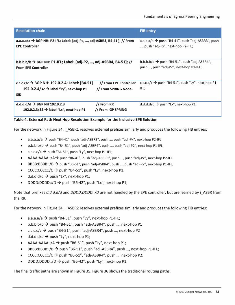
Fundamentals of Egress Peering Engineering
© 2017 Juniper Networks, Inc. 73
Resolution chain FIB entry
a.a.a.a/a BGP NH: P2-IFL; Label: [adj-Px, …, adj-ASBR3, B4-41 ]; // From EPE Controller
a.a.a.a/a push “B4-41”, push “adj-ASBR3”, push …, push “adj-Px”, next-hop P2-IFL;
b.b.b.b/b BGP NH: P1-IFL; Label: [adj-P2, …, adj-ASBR4, B4-51]; // From EPE Controller
b.b.b.b/b push “B4-51”, push “adj-ASBR4”, push …, push “adj-P2”, next-hop P1-IFL;
c.c.c.c/c BGP NH: 192.0.2.4; Label: [B4-51] // From EPE Controller 192.0.2.4/32 label “Ly”, next-hop P1 // From SPRING Node-SID
c.c.c.c/c push “B4-51”, push “Ly”, next-hop P1-IFL;
d.d.d.d/d BGP NH 192.0.2.3 // From RR 192.0.2.3/32 label “Lx”, next-hop P1 // From IGP SPRING
d.d.d.d/d push “Lx”, next-hop P1;
Table 4. External Path Next Hop Resolution Example for the Inclusive EPE Solution
For the network in Figure 34, i_ASBR1 resolves external prefixes similarly and produces the following FIB entries:
• a.a.a.a/a push “B4-41”, push “adj-ASBR3”, push …, push “adj-Px”, next-hop P2-IFL • b.b.b.b/b push “B4-51”, push “adj-ASBR4”, push …, push “adj-P2”, next-hop P1-IFL; • c.c.c.c/c push “B4-51”, push “Ly”, next-hop P1-IFL; • AAAA:AAAA::/A push “B6-41”, push “adj-ASBR3”, push …, push “adj-Px”, next-hop P2-IFL • BBBB:BBBB::/B push “B6-51”, push “adj-ASBR4”, push …, push “adj-P2”, next-hop P1-IFL; • CCCC:CCCC::/C push “B4-51”, push “Ly”, next-hop P1; • d.d.d.d/d push “Lx”, next-hop P1; • DDDD:DDDD::/D push “B6-42”, push “Lx”, next-hop P1;
Note that prefixes d.d.d.d/d and DDDD:DDDD::/D are not handled by the EPE controller, but are learned by i_ASBR from the RR.
For the network in Figure 34, i_ASBR2 resolves external prefixes similarly and produces the following FIB entries:
• a.a.a.a/a push “B4-51”, push “Ly”, next-hop P1-IFL; • b.b.b.b/b push “B4-51”, push “adj-ASBR4”, push …, next-hop P1 • c.c.c.c/c push “B4-51”, push “adj-ASBR4”, push …, next-hop P2 • d.d.d.d/d push “Ly”, next-hop P1; • AAAA:AAAA::/A push “B6-51”, push “Ly”, next-hop P1; • BBBB:BBBB::/B push “B6-51”, push “adj-ASBR4”, push …, next-hop P1-IFL; • CCCC:CCCC::/C push “B6-51”, “adj-ASBR4”, push …, next-hop P2; • DDDD:DDDD::/D push “B6-42”, push “Ly”, next-hop P1;
The final traffic paths are shown in Figure 35. Figure 36 shows the traditional routing paths.
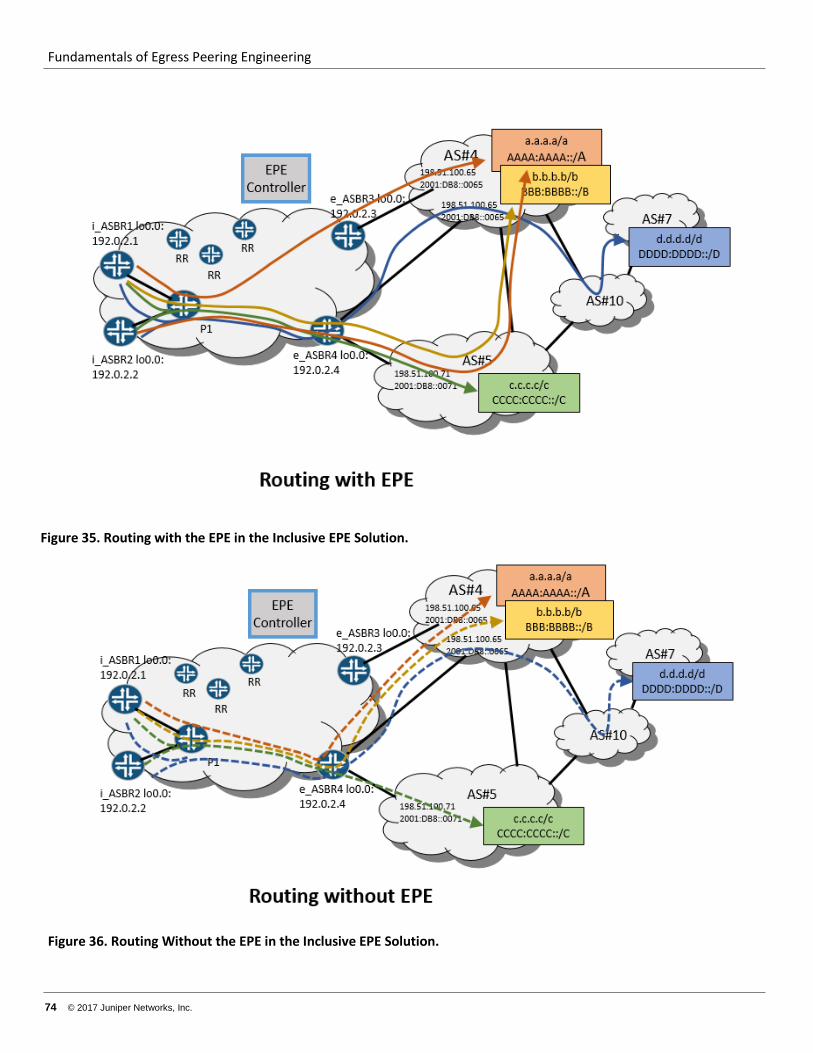
Fundamentals of Egress Peering Engineering
74 © 2017 Juniper Networks, Inc.
Figure 35. Routing with the EPE in the Inclusive EPE Solution.
Figure 36. Routing Without the EPE in the Inclusive EPE Solution.
Fundamentals of Egress Peering Engineering
© 2017 Juniper Networks, Inc. 75
Node Requirements for the Solution In this architecture, the ASBRs need to support:
• IGP, SPRING Node SID • BGP and BGP-LU (RFC3107), with ADD-PATH for IPv4 and IPv6 address families (labeled and unlabeled). • Push of three MPLS headers onto packet (for if FRR/LFA is desired) • IPv4-mapped IPv6 addresses and routes.
The core routers need to support:
• IGP, SPRING Node SID • MPLS
The RR needs to support BGP and BGP-LU (RFC3107), with ADD-PATH for the IPv4 and IPv6 address families (labeled and unlabeled).
The EPE controller needs to support BGP with ADD-PATH for the IPv4 and IPv6 address families (labeled and unlabeled).
Redundancy, convergence and fast restoration The NNI Failure Case
Failure of an NNI would be detected as either an interface down event or an eBGP session down event. In both cases, the impacted e_ASBR would withdraw the affected prefixes from the RR and from the EPE controller. The e_ASBR also would withdraw the path to the peer ASBR interface’s IP address that conveys the EPE cookie from the RR.
One of the two paths learned by the i_ASBR from the EPE controller by way of BGP ADD-PATH is preferred to the other path. The preferred path—or both paths—might point to the faulty NNI. If the impacted path is the active one, then the EPE controller would do one of the following:
• Withdraw the path that has the EPE cookie label in the NLRI • Advertise the new best path for each [i_ASBR, destination prefix] pair • Withdraw the secondary path and advertise the new one (if needed)
If the e_ASBR supports BGP PIC edge functionality for the above scenario and topology, switching to backup path might be faster (sub-second).
This procedure requires failure propagation over the network from the e_ASBR all the way to the i_ASBR. This action might take tens or even hundreds of milliseconds. During this interval, traffic might be lost. In order to reduce time of traffic loss, local protection at point of failure is needed. In the Junos OS, the egress-te feature enables this protection. See http://www.juniper.net/techpubs/en_US/junos16.1/topics/task/configuration/configuring-egress-te-using-bgp-lu.html for more information.
Fundamentals of Egress Peering Engineering
76 © 2017 Juniper Networks, Inc.
If an NNI fails, the adjacent e_ASBR sends traffic to one of the following:
• Another local NNI. • Another NNI on another e_ASBR. This is done by switching traffic from an LDP LSP tunnel to a backup e_ASBR
and pushing the EPE cookie label (learned from an RR) that points to this other NNI.
This technique reduces traffic loss time to the tens of milliseconds.
The e_ASBR Failure Case
Failure of an e_ASBR uses a network convergence process similar to an NNI failure. The only difference is that, in addition to BGP routes withdrawal, the IGP route leading to the e_ASBR loopback address and its associated LSP are also removed. Because an IGP is usually faster than BGP to converge, removal of the e_ASBR loopback address and LSP is the initial event seen by i_ASBR. This event deactivates all of the BGP paths that use this address and next hop.
Because an EPE controller provides two diverse routes to reach NNIs for each prefix, an i_ASBR locally switches traffic to the backup NNI.
Finally, when the EPE controller calculates a new “best exit” NNI and a new different backup NNI, the controller updates i_ASBR with this information, which then replaces the two old BGP routes.
The Inta_AS Links or Internal Node Failures
Failure of intra-AS links of internal nodes are primarily handled by simple IGP convergence. Optionally, this process could be augmented by BFD in order to speed up detection of some types of failures. For fast restoration, the network could use LFA or R-LFA, augmented by an explicit or dynamic (that is, TI-FRR) backup LSP.
Recommended