DYWIDAG Bonded Post-Tensioning Systems using Strands
2
Contents ����������������������������������������������������������������������������������������������������������������������������������������������������������������������������������������������� 3
DYWIDAG Post-Tensioning Systems ���������������������������������������������������������������������������������������������������������������������������������������������������� 4
Standard Strands ���������������������������������������������������������������������������������������������������������������������������������������������������������������������������������� 6
Corrugated Duct ����������������������������������������������������������������������������������������������������������������������������������������������������������������������������������� 7
PE/PP Round Duct �������������������������������������������������������������������������������������������������������������������������������������������������������������������������������� 8
ETA Approvals��������������������������������������������������������������������������������������������������������������������������������������������������������������������������������������� 9
Anchorages ���������������������������������������������������������������������������������������������������������������������������������������������������������������������������������������� 10
Overview ��������������������������������������������������������������������������������������������������������������������������������������������������������������������������������������������� 13
Installation ������������������������������������������������������������������������������������������������������������������������������������������������������������������������������������������ 16
Stressing ��������������������������������������������������������������������������������������������������������������������������������������������������������������������������������������������� 18
Grouting ���������������������������������������������������������������������������������������������������������������������������������������������������������������������������������������������� 19
Multiplane Anchorage MA with Helix Reinforcement (Minimum Anchor Body Dimensions)����������������������������������������������������������������� 20
Multiplane Anchorage MA without Helix Reinforcement ��������������������������������������������������������������������������������������������������������������������� 22
Plate Anchorage SD ���������������������������������������������������������������������������������������������������������������������������������������������������������������������������� 24
Plate Anchorage ED ���������������������������������������������������������������������������������������������������������������������������������������������������������������������������� 25
Coupler R �������������������������������������������������������������������������������������������������������������������������������������������������������������������������������������������� 26
Coupler D �������������������������������������������������������������������������������������������������������������������������������������������������������������������������������������������� 27
Loop Anchorage HV ���������������������������������������������������������������������������������������������������������������������������������������������������������������������������� 28
Bond Head Anchorage HL/HR ������������������������������������������������������������������������������������������������������������������������������������������������������������ 29
Coupler M/ME (Floating Anchorage Block) ����������������������������������������������������������������������������������������������������������������������������������������� 30
Flat Multiplane Anchorage FMA ���������������������������������������������������������������������������������������������������������������������������������������������������������� 31
Equipment Overview ������������������������������������������������������������������������������������������������������������������������������������������������������������������������� 32
Calculation of Elongation �������������������������������������������������������������������������������������������������������������������������������������������������������������������� 36
References ����������������������������������������������������������������������������������������������������������������������������������������������������������������������������������������� 38
Addresses ������������������������������������������������������������������������������������������������������������������������������������������������������������������������������������������� 46
Contents
3
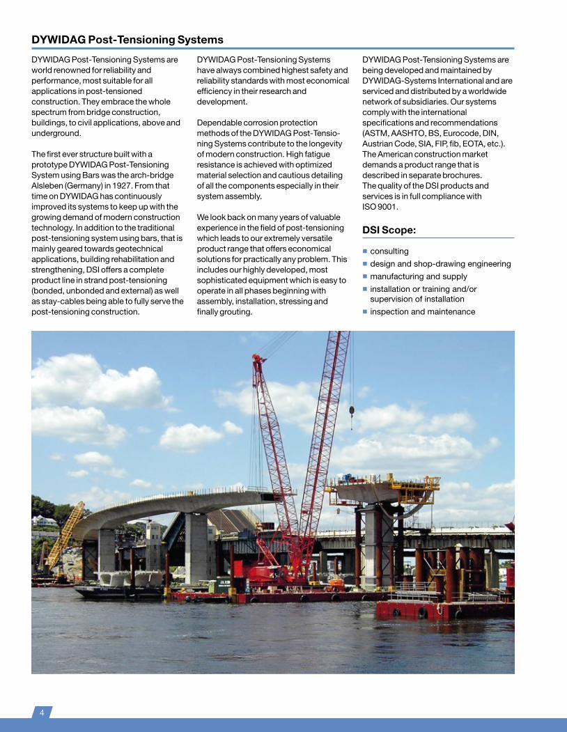
DYWIDAG Post-Tensioning Systems are world renowned for reliability and performance, most suitable for all applica tions in post-tensioned construction. They embrace the whole spectrum from bridge construction, buildings, to civil applications, above and underground.
The first ever structure built with a prototype DYWIDAG Post-Tensioning System using Bars was the arch-bridge Alsleben (Germany) in 1927. From that time on DYWIDAG has continuously improved its systems to keep up with the growing demand of modern construction technology. In addition to the traditional post-tensioning system using bars, that is mainly geared towards geotechnical applications, building rehabilitation and strengthening, DSI offers a complete product line in strand post-tensioning (bonded, unbonded and external) as well as stay-cables being able to fully serve the post- tensioning construction.
DYWIDAG Post-Tensioning Systems have always combined highest safety and reliability standards with most economical efficiency in their re search and development.
Dependable corrosion protection methods of the DYWIDAG Post-Tensio-ning Systems contribute to the longevity of modern construction. High fatigue resistance is achieved with optimized material selection and cautious detailing of all the components especially in their system assembly.
We look back on many years of valuable experience in the field of post-tensioning which leads to our extremely versatile product range that offers economical solutions for practically any problem. This includes our highly developed, most sophisticated equipment which is easy to operate in all phases beginning with assembly, installa tion, stressing and finally grouting.
DYWIDAG Post-Tensioning Systems are being deve loped and maintained by DYWIDAG-Systems International and are serviced and distributed by a worldwide network of subsidiaries. Our systems comply with the international specifications and recommendations (ASTM, AASHTO, BS, Eurocode, DIN, Austrian Code, SIA, FIP, fib, EOTA, etc.). The American construction market demands a product range that is described in separate brochures. The quality of the DSI products and services is in full compliance with ISO 9001.
DSI Scope:
■ consulting ■ design and shop-drawing engineering ■ manufacturing and supply ■ installation or training and/or supervision of installation
■ inspection and maintenance
DYWIDAG Post-Tensioning Systems
4
DYWIDAG Post-Tensioning Systems
5
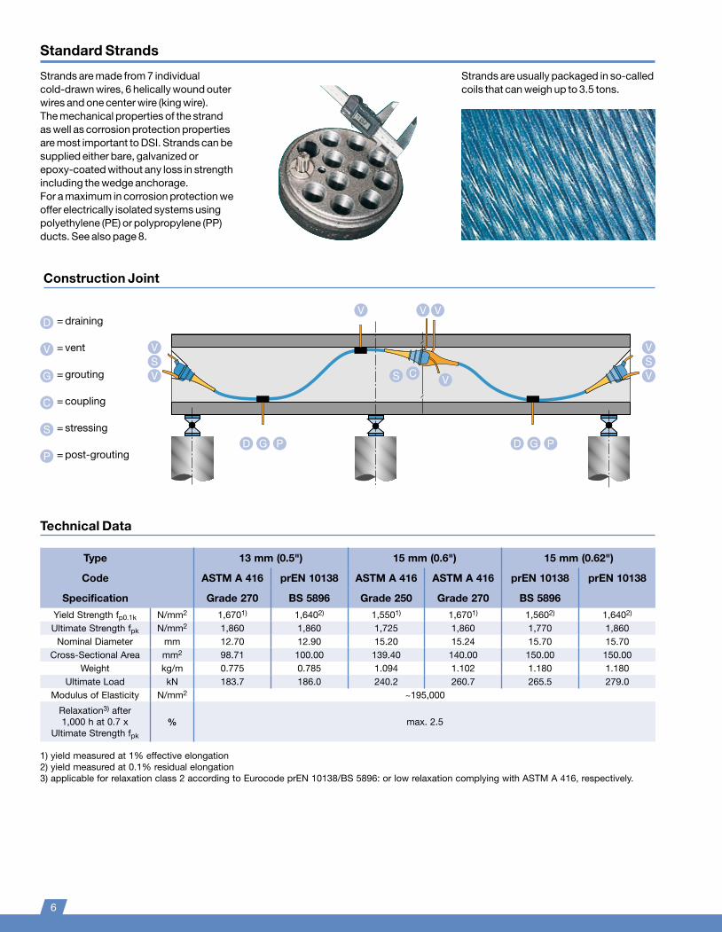
Strands are made from 7 individual cold-drawn wires, 6 helically wound outer wires and one center wire (king wire). The mechanical properties of the strand as well as corrosion protection properties are most important to DSI. Strands can be supplied either bare, galvanized or epoxy-coated with out any loss in strength including the wedge anchorage. For a maximum in corrosion protection we offer electrically isolated systems using polyethylene (PE) or polypropyl ene (PP) ducts. See also page 8.
Strands are usually packaged in so-called coils that can weigh up to 3.5 tons.
Technical Data
V V V
D G PD G P
VSV
= draining
= vent
= grouting
= coupling
= stressing
= post-grouting
D
V
G
C
S
P
VSVS C
V
Construction Joint
Standard Strands
Type 13 mm (0.5") 15 mm (0.6") 15 mm (0.62")
Code ASTM A 416 prEN 10138 ASTM A 416 ASTM A 416 prEN 10138 prEN 10138
Specification Grade 270 BS 5896 Grade 250 Grade 270 BS 5896
Yield Strength fp0.1k N/mm2 1,6701) 1,6402) 1,5501) 1,6701) 1,5602) 1,6402)
Ultimate Strength fpk N/mm2 1,860 1,860 1,725 1,860 1,770 1,860Nominal Diameter mm 12.70 12.90 15.20 15.24 15.70 15.70
Cross-Sectional Area mm2 98.71 100.00 139.40 140.00 150.00 150.00Weight kg/m 0.775 0.785 1.094 1.102 1.180 1.180
Ultimate Load kN 183.7 186.0 240.2 260.7 265.5 279.0Modulus of Elasticity N/mm2 ~195,000
Relaxation3) after 1,000 h at 0.7 x
Ultimate Strength fpk
% max. 2.5
1) yield measured at 1% effective elongation2) yield measured at 0.1% residual elongation3) applicable for relaxation class 2 according to Eurocode prEN 10138/BS 5896: or low relaxation complying with ASTM A 416, respectively.
6
O.D.
I.D.
O.D.
I.D.
The tendon type number (e.g. 5901, 6801) is composed as follows: the first digit (5 or 6) identifies the nominal strand diameter in tenth of inches, i.e. 0.5" or 0.6"/ 0.62", the last two digits (…01) reference the number of used strands (= 1 strand). The second digit is an internal code. As regards the 0.6" tendon types, the accessories fit both Grade 250 (GUTS 1770 N/mm2) and Grade 270 (GUTS 1860 N/mm2) strands.
Metal ducts represent the most economical means to create a void for tensile elements. These thin-walled (0.25 - 0.60 mm), ribbed sheet metal ducts provide a fair secondary corrosion
protection with excellent bond behavior between tendon and concrete. Primary corrosion protection is provided by the alkalinity of grout and concrete.
Corrugated Duct
Dimensions of Corrugated Duct (Standard Sizes)
Tendon Type Sheating
0.5" 0.6"/0.62" I.D. O.D.
mm mm
5901 6801 25 305902 6802 40 455904 6803 45 505905 6804 50 555907 6805 55 605909 6807 60 655912 6809 70 755915 6812 80 855920 6815 85 905927 6819 95 1005932 6822 100 1055937 6827 110 117
– 6831 120 127– 6837 130 137– 6843 140 147– 6849 150 157– 6855 160 167
Tendon Type Support Distances
up to1)
Woble Coefficent
Friction Coefficient0.5" 0.6"/0.62"
mm rad/m rad-1
5901 6801 1.0 5 x 10⁻³ 0.195902 6802 1.0 5 x 10⁻³ 0.195904 6803 1.0 5 x 10⁻³ 0.195905 6804 1.0 5 x 10⁻³ 0.195907 6805 1.0 5 x 10⁻³ 0.195909 6807 1.5 5 x 10⁻³ 0.195912 6809 1.5 5 x 10⁻³ 0.195915 6812 1.5 5 x 10⁻³ 0.195920 6815 1.8 5 x 10⁻³ 0.195927 6819 1.8 5 x 10⁻³ 0.195932 6822 1.8 5 x 10⁻³ 0.195937 6827 1.8 5 x 10⁻³ 0.19
– 6831 1.8 5 x 10⁻³ 0.19– 6837 1.8 5 x 10⁻³ 0.19– 6843 1.8 5 x 10⁻³ 0.19– 6849 1.8 5 x 10⁻³ 0.19– 6855 1.8 5 x 10⁻³ 0.19
1) 1.0-1.8 m with stiffening, e.g. with PE tube; 0.8-1.5 m with strengthened ductIn tendon section with minimum radius of curvature a distance of 0.6-1.2 m shall apply.
7
Thick-walled polyethylene/polypropylene plastic ducts provide long-term secondary corrosion protection especially in aggressive environments such as in case of waste water treatment plants, acid tanks, silos or structures exposed to de-icing salts.
DYWIDAG-Systems International offers polyethylene/polypropylene ducts in straight lengths up to ≈24 m for all sizes. Standard shipping length is ≈12 m. Longer lengths in coils are available for all sizes except 130 mm.
PE/PP Round Duct
Flat PE/PP Duct
Dimensions of Round Corrugated PE/PP Duct (Standard Size)
Tendon Type Sheating Wall Thickness
0.5" 0.6"/0.62" I.D. O.D.
mm mm mm
5907 6805 48 59 2.05909 6807 59 73 2.05912 6809 76 91 2.55915 6812 76 91 2.55920 6815 85 100 2.55927 6819 100 116 3.05932 6822 100 116 3.05937 6827 115 135 3.5
– 6837 130 151 4.0
Tendon Type A B a b Wall Thickness
0.5" 0.6" mm mm mm mm mm
5902 6802 52.5 36.5 37.5 21.5 2.05904 6803 85.5 36.0 71.0 21.0 2.05905 6804 90.0 40.0 75.5 25.0 2.05907 6805 105.0 40.0 91.0 22.0 2.0
8
Construction products with an European Technical Approval (ETA) meet all essential demands given in the Construction Products Regulation (CPR).
The ETA holder is authorized to apply the CE-marking (Conformité Européenne) on his product. The CE-marking certifies the conformity with the technical specification and is the basis for the free movement of goods within the EU member states.
DSI is proud to have European Technical Approvals for its PT-systems with bars, bonded strands and unbonded strands.
ETA Approvals
9
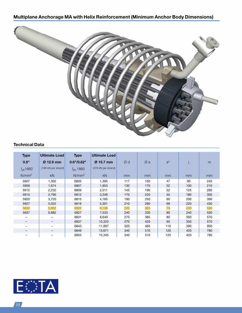
The two-part multiplane an chorage is primarily used for longitudinal tendons in beams and bridges.
The wedge plate and the multiplane anchor body with usually three load transfer planes introduce the pre-stressing force continuously into the member with minimal front area. The MA anchorage can be installed with and without helix reinforcement.
The separation of anchor body and wedge plate makes it possible to insert the strand after casting the concrete. The wedge plate self-centers on the anchor body providing consistent assembly and installation as well as trouble-free stressing.
Stressing Dead End Anchorage Ultimate Load Anchorage Accessible not Accessible kN from to
9 9 9 1,201 15,345
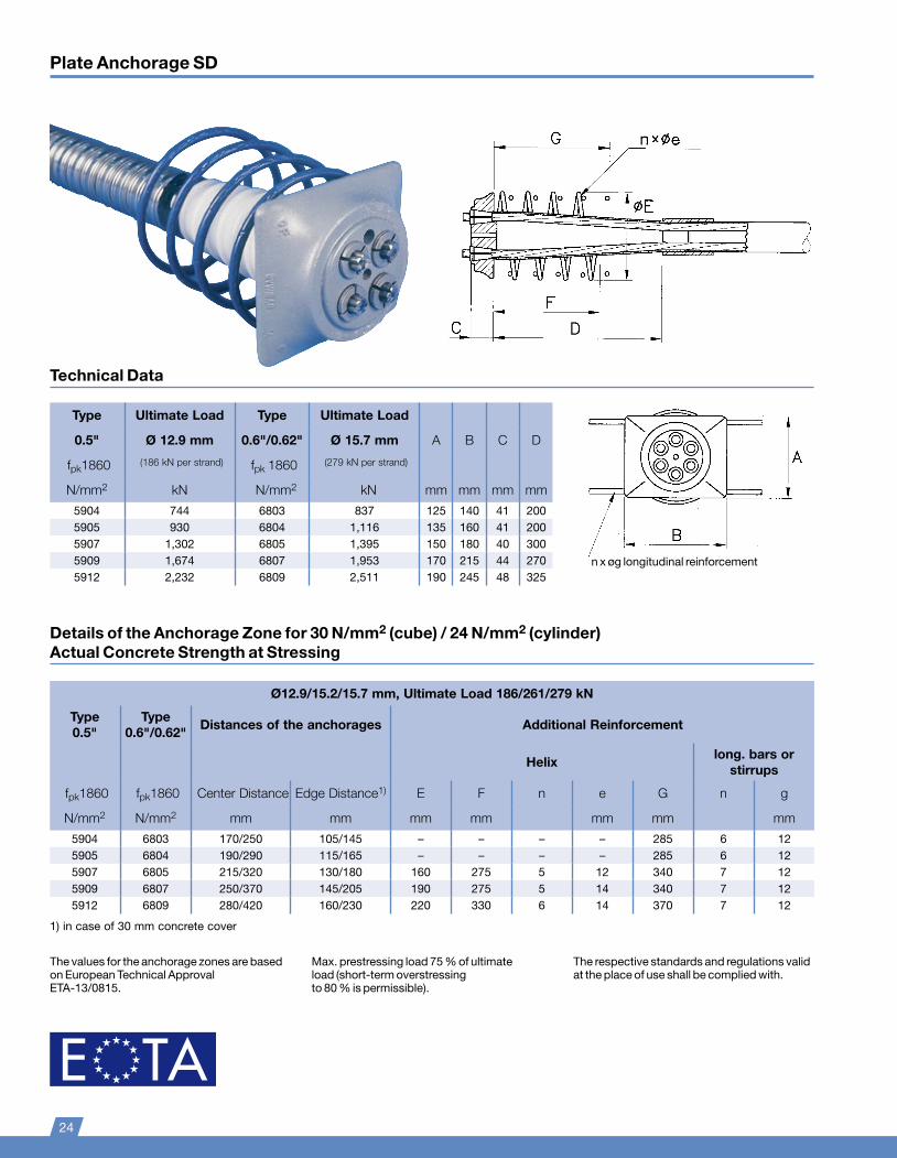
The two-part plate anchorage can be used in slabs and similar structures, e.g. transversal prestressing in bridge decks. The wedge plate self-centers on the anchor plate providing consistent assembly and installation as well as trouble-free stressing.
Stressing Dead End Anchorage Ultimate Load Anchorage Accessible not Accessible kN from to
9 9 9 721 1.395
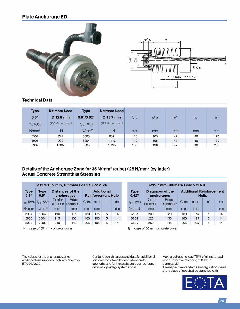
The single unit plate anchor age is designed for plate struc tures as well as trans verse tendons in bridges. Small edge and center dis tances allow for an economical anchorage layout in condensed situations.
Stressing Dead End Anchorage Ultimate Load Anchorage Accessible not Accessible kN from to
9 9 9 721 2,511
Multiplane Anchorage MA
Plate Anchorage SD
Plate Anchorage Type ED
Anchorages
10
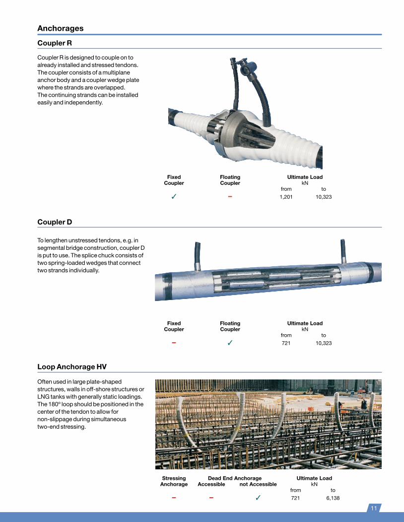
Coupler R is designed to couple on to already installed and stressed tendons. The coupler consists of a multiplane anchor body and a coupler wedge plate where the strands are overlapped. The continuing strands can be installed easily and independently.
Fixed Floating Ultimate Load Coupler Coupler kN from to
9 – 1,201 10,323
To lengthen unstressed tendons, e.g. in segmental bridge construction, coupler D is put to use. The splice chuck consists of two spring-loaded wedges that connect two strands individually.
Fixed Floating Ultimate Load Coupler Coupler kN from to
– 9 721 10,323
Often used in large plate-shaped structures, walls in off-shore structures or LNG tanks with generally static loadings. The 180º loop should be positioned in the center of the tendon to allow for non-slippage during simultaneous two-end stressing.
Stressing Dead End Anchorage Ultimate Load Anchorage Accessible not Accessible kN from to
– – 9 721 6,138
Coupler R
Coupler D
Loop Anchorage HV
Anchorages
11
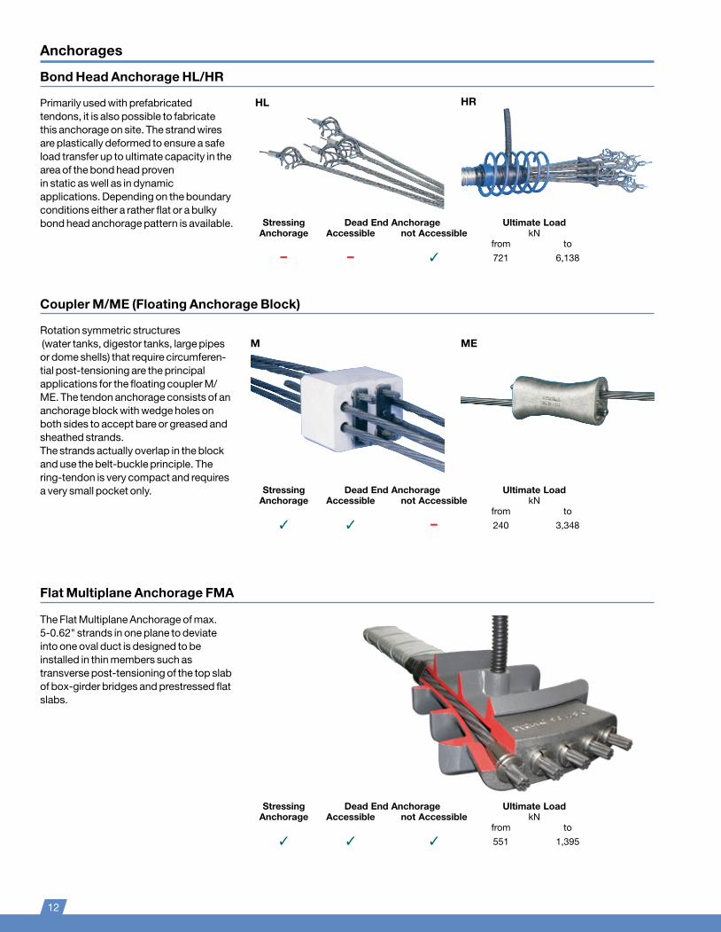
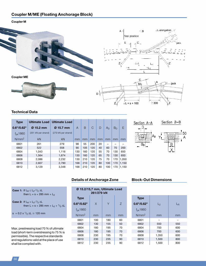
Rotation symmetric structures (water tanks, digestor tanks, large pipes or dome shells) that require circumferen-tial post-tensioning are the principal applications for the floating coupler M/ME. The tendon anchorage consists of an anchorage block with wedge holes on both sides to accept bare or greased and sheathed strands. The strands actually overlap in the block and use the belt-buckle principle. The ring-tendon is very compact and requires a very small pocket only. Stressing Dead End Anchorage Ultimate Load
Anchorage Accessible not Accessible kN from to
9 9 – 240 3,348
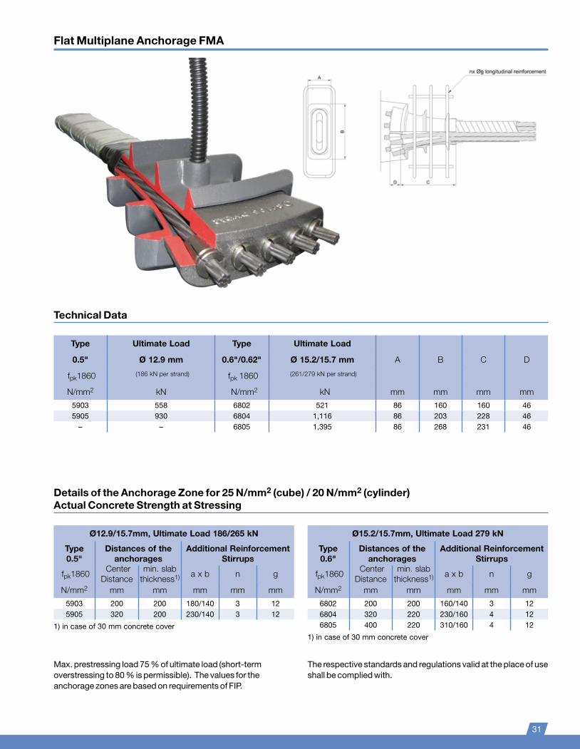
The Flat Multiplane Anchorage of max. 5-0.62" strands in one plane to deviate into one oval duct is designed to be installed in thin members such as transverse post-tensioning of the top slab of box-girder bridges and prestressed flat slabs.
Stressing Dead End Anchorage Ultimate Load Anchorage Accessible not Accessible kN from to
9 9 9 551 1,395
Primarily used with prefabricated tendons, it is also possible to fabricate this anchorage on site. The strand wires are plastically deformed to ensure a safe load transfer up to ultimate capacity in the area of the bond head proven in static as well as in dynamic applications. Depending on the boundary conditions either a rather flat or a bulky bond head anchorage pattern is available. Stressing Dead End Anchorage Ultimate Load
Anchorage Accessible not Accessible kN from to
– – 9 721 6,138
MEM
HL HR
Coupler M/ME (Floating Anchorage Block)
Flat Multiplane Anchorage FMA
Bond Head Anchorage HL/HR
Anchorages
12
Overview
Tendon Type 59…
Tendon Type 68…
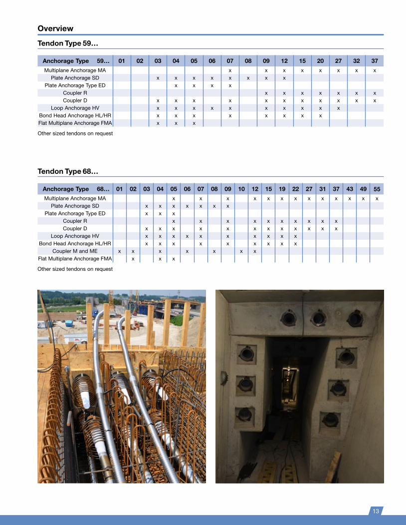
Anchorage Type 59… 01 02 03 04 05 06 07 08 09 12 15 20 27 32 37
Multiplane Anchorage MA x x x x x x x xPlate Anchorage SD x x x x x x x x
Plate Anchorage Type ED x x x xCoupler R x x x x x x xCoupler D x x x x x x x x x x x
Loop Anchorage HV x x x x x x x x x xBond Head Anchorage HL/HR x x x x x x x xFlat Multiplane Anchorage FMA x x x
Other sized tendons on request
Anchorage Type 68… 01 02 03 04 05 06 07 08 09 10 12 15 19 22 27 31 37 43 49 55
Multiplane Anchorage MA x x x x x x x x x x x x xPlate Anchorage SD x x x x x x x
Plate Anchorage Type ED x x xCoupler R x x x x x x x x x xCoupler D x x x x x x x x x x x x
Loop Anchorage HV x x x x x x x x x xBond Head Anchorage HL/HR x x x x x x x x x
Coupler M and ME x x x x x x xFlat Multiplane Anchorage FMA x x x
Other sized tendons on request
13
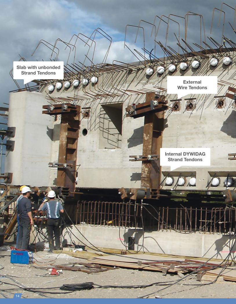
Slab with unbondedStrand Tendons
External Wire Tendons
Internal DYWIDAG Strand Tendons
14
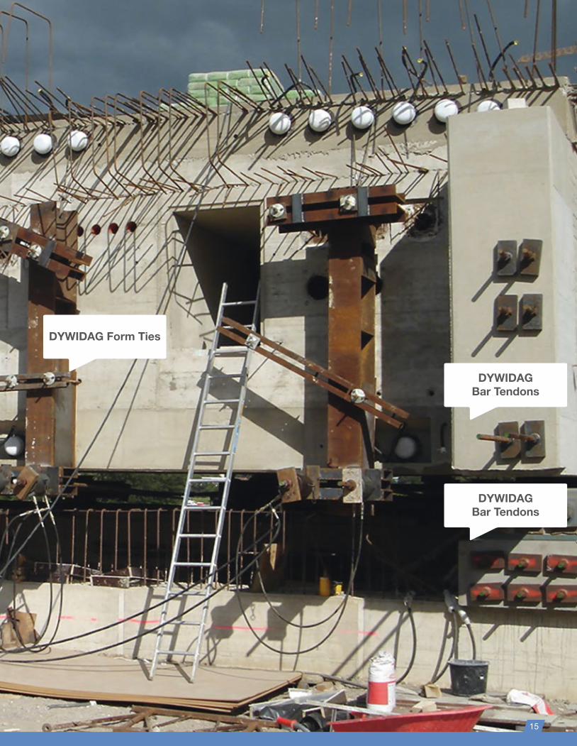
DYWIDAG Form Ties
DYWIDAG Bar Tendons
DYWIDAG Bar Tendons
15
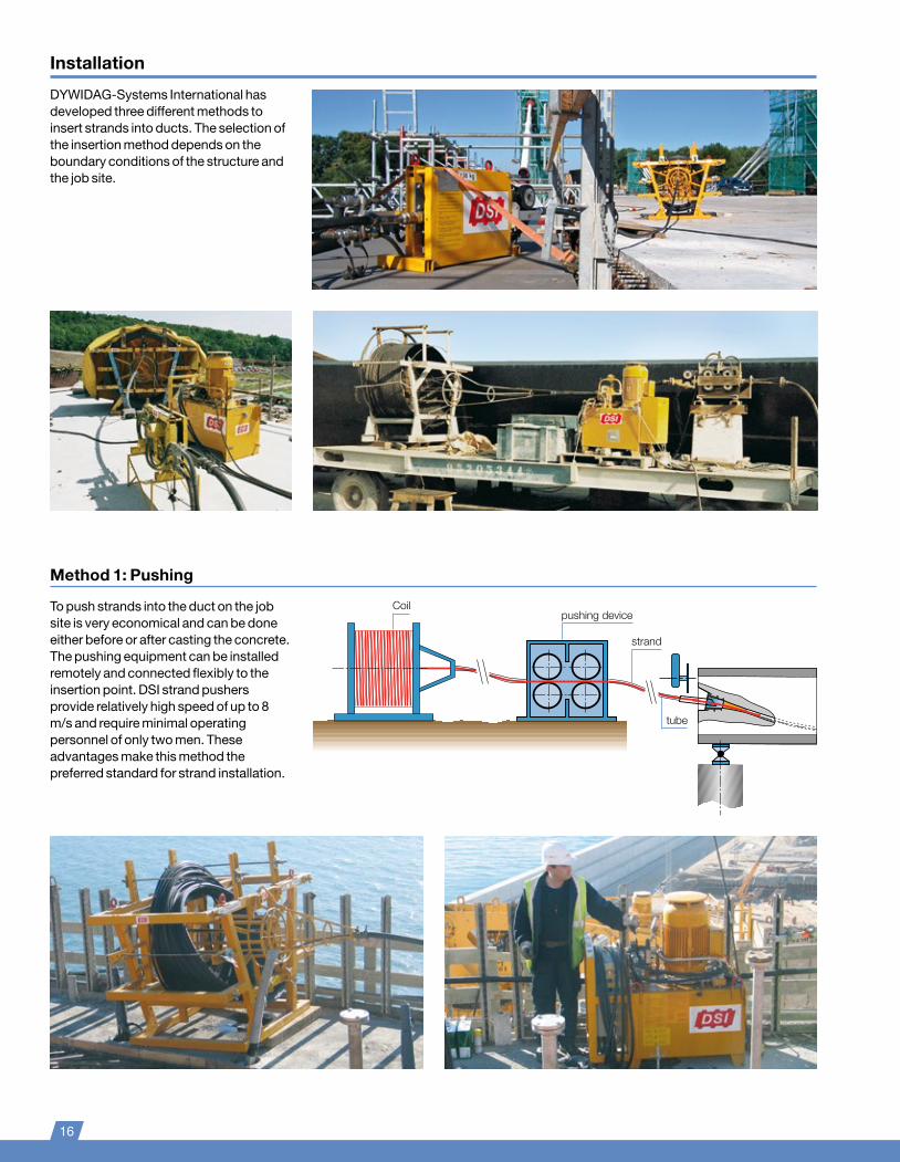
DYWIDAG-Systems Inter national has developed three different methods to insert strands into ducts. The selection of the insertion method depends on the boundary conditions of the structure and the job site.
To push strands into the duct on the job site is very economical and can be done either before or after casting the concrete. The pushing equipment can be installed remotely and connected flexibly to the insertion point. DSI strand pushers provide relatively high speed of up to 8 m/s and require minimal operating personnel of only two men. These advantages make this method the preferred standard for strand installation.
Installation
Method 1: Pushing
Coilpushing device
strand
tube
16
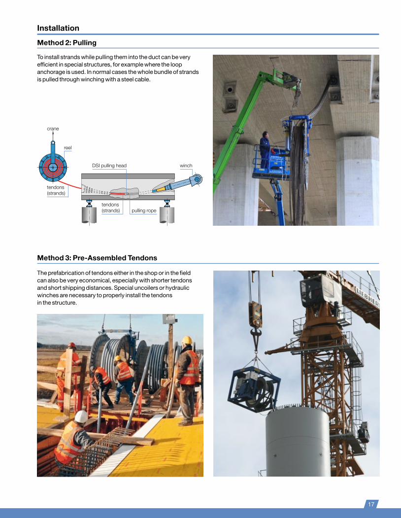
To install strands while pulling them into the duct can be very efficient in special structures, for example where the loop anchorage is used. In normal cases the whole bundle of strands is pulled through winching with a steel cable.
The prefabrication of tendons either in the shop or in the field can also be very economical, especially with shorter tendons and short shipping distances. Special uncoilers or hydraulic winches are necessary to properly install the tendons in the structure.
Method 2: Pulling
Method 3: Pre-Assembled Tendons
Installation
crane
reel
tendons (strands)
tendons (strands)
DSI pulling head
pulling rope
winch
17
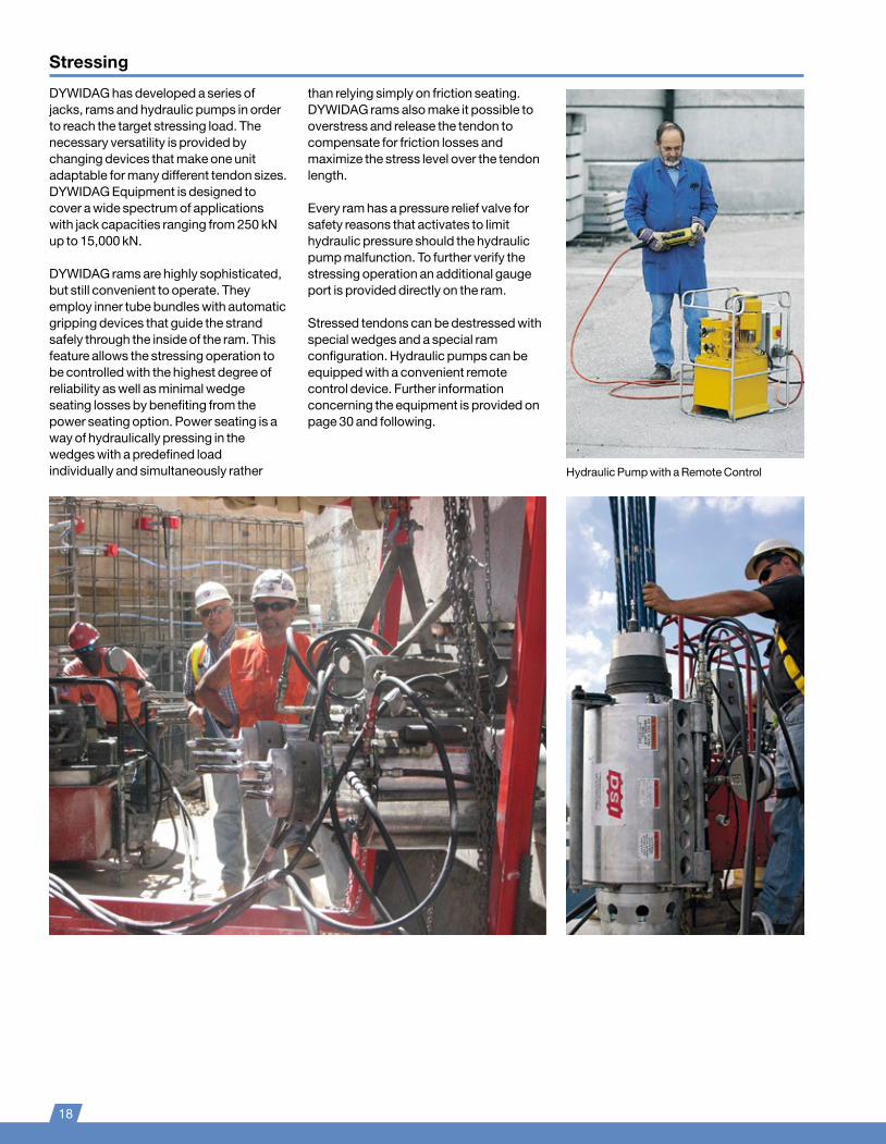
DYWIDAG has developed a series of jacks, rams and hydraulic pumps in order to reach the target stressing load. The necessary versatility is provided by changing devices that make one unit adaptable for many different tendon sizes. DYWIDAG Equipment is designed to cover a wide spectrum of applications with jack capacities ranging from 250 kN up to 15,000 kN.
DYWIDAG rams are highly sophisti cated, but still convenient to operate. They employ inner tube bundles with automatic gripping devices that guide the strand safely through the inside of the ram. This feature allows the stressing operation to be controlled with the highest degree of reliability as well as minimal wedge seating losses by benefiting from the power seating option. Power seating is a way of hydraulically pressing in the wedges with a predefined load individually and simultaneously rather
than relying simply on friction seating. DYWIDAG rams also make it possible to overstress and release the tendon to compensate for friction losses and maximize the stress level over the tendon length.
Every ram has a pressure relief valve for safety reasons that activates to limit hydraulic pressure should the hydraulic pump malfunction. To further verify the stressing operation an additional gauge port is provided directly on the ram.
Stressed tendons can be destressed with special wedges and a special ram configuration. Hydraulic pumps can be equipped with a convenient remote control device. Further information concerning the equipment is provided on page 30 and following.
Hydraulic Pump with a Remote Control
Stressing
18
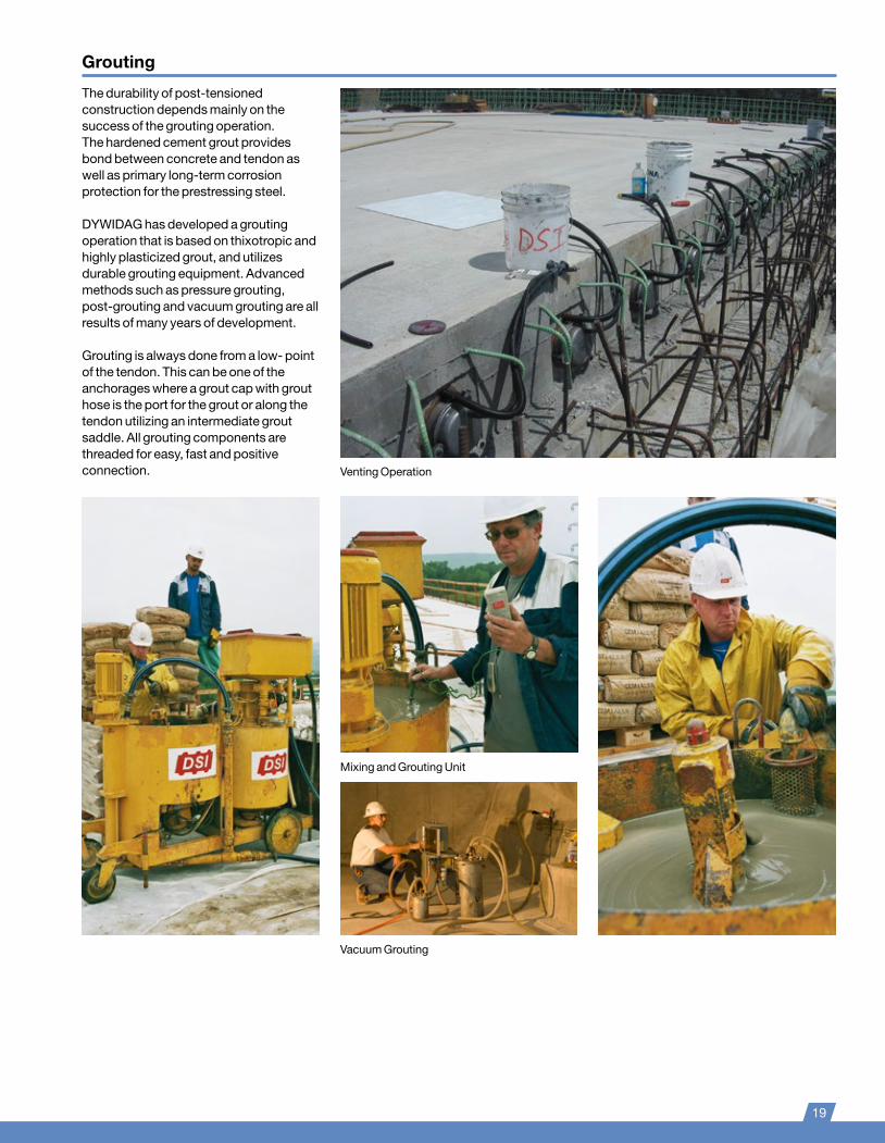
The durability of post-tensioned construction depends mainly on the success of the grouting operation. The hardened cement grout provides bond between concrete and tendon as well as primary long-term corrosion protection for the prestressing steel.
DYWIDAG has developed a grouting operation that is based on thixotropic and highly plasticized grout, and utilizes durable grouting equipment. Advanced methods such as pressure grouting, post-grouting and vacuum grouting are all results of many years of development.
Grouting is always done from a low- point of the tendon. This can be one of the an chorages where a grout cap with grout hose is the port for the grout or along the tendon utilizing an inter mediate grout saddle. All grouting components are threaded for easy, fast and positive connection.
Vacuum Grouting
Mixing and Grouting Unit
Venting Operation
Grouting
19
Technical Data
Multiplane Anchorage MA with Helix Reinforcement (Minimum Anchor Body Dimensions)
Type Ultimate Load Type Ultimate Load
0.5" Ø 12.9 mm 0.6"/0.62" Ø 15.7 mm Ø d Ø a e* j m
fpk1860 (186 kN per strand) fpk 1860 (279 kN per strand)
N/mm2 kN N/mm2 kN mm mm mm mm mm
5907 1,302 6805 1,395 117 150 47 90 2405909 1,674 6807 1,953 130 170 52 100 2105912 2,232 6809 2,511 145 190 52 125 2805915 2,790 6812 3,348 170 220 55 180 3505920 3,720 6815 4,185 190 250 60 200 3905927 5,022 6819 5,301 210 280 68 220 4305932 5,952 6822 6,138 220 305 73 220 5505937 6,882 6827 7,533 240 330 80 240 550
– – 6831 8,649 270 385 80 350 570– – 6837 10,323 270 420 95 350 570– – 6843 11,997 320 465 110 380 950– – 6849 13,671 340 510 120 420 780– – 6855 15,345 340 510 120 420 780
20
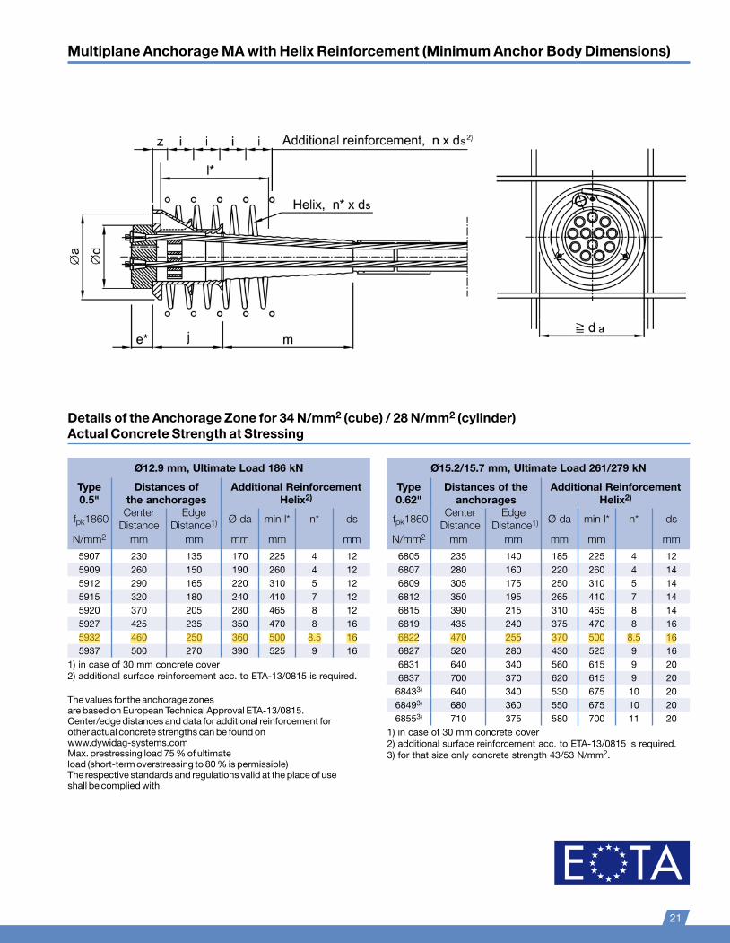
Details of the Anchorage Zone for 34 N/mm2 (cube) / 28 N/mm2 (cylinder) Actual Concrete Strength at Stressing
The values for the anchorage zones are based on European Technical Approval ETA-13/0815. Center/edge distances and data for additional reinforcement for other actual concrete strengths can be found on www.dywidag-systems.com Max. prestressing load 75 % of ultimate load (short-term overstressing to 80 % is permissible) The respective standards and regulations valid at the place of use shall be complied with.
Multiplane Anchorage MA with Helix Reinforcement (Minimum Anchor Body Dimensions)
Ø12.9 mm, Ultimate Load 186 kN
Type 0.5"
Distances of the anchorages
Additional Reinforcement Helix2)
fpk1860Center
DistanceEdge
Distance1) Ø da min l* n* ds
N/mm2 mm mm mm mm mm
5907 230 135 170 225 4 125909 260 150 190 260 4 125912 290 165 220 310 5 125915 320 180 240 410 7 125920 370 205 280 465 8 125927 425 235 350 470 8 165932 460 250 360 500 8.5 165937 500 270 390 525 9 16
1) in case of 30 mm concrete cover2) additional surface reinforcement acc. to ETA-13/0815 is required.
Ø15.2/15.7 mm, Ultimate Load 261/279 kN
Type 0.62"
Distances of the anchorages
Additional Reinforcement Helix2)
fpk1860 Center
DistanceEdge
Distance1) Ø da min l* n* ds
N/mm2 mm mm mm mm mm
6805 235 140 185 225 4 126807 280 160 220 260 4 146809 305 175 250 310 5 146812 350 195 265 410 7 146815 390 215 310 465 8 146819 435 240 375 470 8 166822 470 255 370 500 8.5 166827 520 280 430 525 9 166831 640 340 560 615 9 206837 700 370 620 615 9 20
68433) 640 340 530 675 10 2068493) 680 360 550 675 10 2068553) 710 375 580 700 11 20
1) in case of 30 mm concrete cover 2) additional surface reinforcement acc. to ETA-13/0815 is required. 3) for that size only concrete strength 43/53 N/mm2.
21
Technical Data
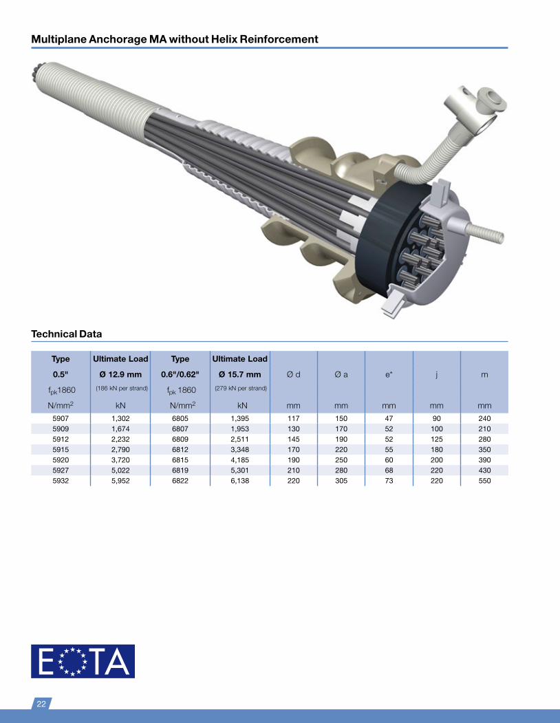
Multiplane Anchorage MA without Helix Reinforcement
Type Ultimate Load Type Ultimate Load
0.5" Ø 12.9 mm 0.6"/0.62" Ø 15.7 mm Ø d Ø a e* j m
fpk1860 (186 kN per strand) fpk 1860 (279 kN per strand)
N/mm2 kN N/mm2 kN mm mm mm mm mm
5907 1,302 6805 1,395 117 150 47 90 2405909 1,674 6807 1,953 130 170 52 100 2105912 2,232 6809 2,511 145 190 52 125 2805915 2,790 6812 3,348 170 220 55 180 3505920 3,720 6815 4,185 190 250 60 200 3905927 5,022 6819 5,301 210 280 68 220 4305932 5,952 6822 6,138 220 305 73 220 550
22
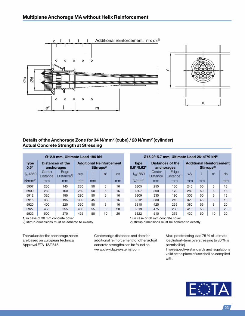
The values for the anchorage zones are based on European Technical Approval ETA-13/0815.
Center/edge distances and data for additional reinforcement for other actual concrete strengths can be found on www.dywidag-systems.com
Max. prestressing load 75 % of ultimate load (short-term overstressing to 80 % is permissible). The respective standards and regulations valid at the place of use shall be complied with.
Details of the Anchorage Zone for 34 N/mm2 (cube) / 28 N/mm2 (cylinder) Actual Concrete Strength at Stressing
Multiplane Anchorage MA without Helix Reinforcement
Ø12.9 mm, Ultimate Load 186 kN
Type 0.5"
Distances of the anchorages
Additional Reinforcement Stirrups2)
fpk1860 Center Distance
Edge Distance1) x/y i n* ds
N/mm2 mm mm mm mm mm
5907 250 145 230 50 5 165909 280 160 260 50 6 165912 320 180 290 50 6 165915 350 195 300 45 8 165920 400 220 360 50 8 165927 465 255 400 55 8 205932 500 270 425 50 10 20
1) in case of 30 mm concrete cover 2) stirrup dimensions must be adhered to exactly
Ø15.2/15.7 mm, Ultimate Load 261/279 kN"
Type 0.6"/0.62"
Distances of the anchorages
Additional Reinforcement Stirrups2)
fpk1860 Center Distance
Edge Distance1) x/y i n* ds
N/mm2 mm mm mm mm mm
6805 255 150 240 50 5 166807 300 170 280 50 6 166809 335 190 305 50 6 166812 380 210 320 45 8 166815 425 235 380 55 8 206819 475 260 410 55 8 206822 510 275 430 50 10 20
1) in case of 30 mm concrete cover 2) stirrup dimensions must be adhered to exactly
23
The values for the anchorage zones are based on European Technical Approval ETA-13/0815.
Max. prestressing load 75 % of ultimate load (short-term overstressing to 80 % is permissible).
The respective standards and regulations valid at the place of use shall be complied with.
Details of the Anchorage Zone for 30 N/mm2 (cube) / 24 N/mm2 (cylinder) Actual Concrete Strength at Stressing
Technical Data
n x øg longitudinal reinforcement
Plate Anchorage SD
Type Ultimate Load Type Ultimate Load
0.5" Ø 12.9 mm 0.6"/0.62" Ø 15.7 mm A B C D
fpk1860 (186 kN per strand) fpk 1860 (279 kN per strand)
N/mm2 kN N/mm2 kN mm mm mm mm
5904 744 6803 837 125 140 41 2005905 930 6804 1,116 135 160 41 2005907 1,302 6805 1,395 150 180 40 3005909 1,674 6807 1,953 170 215 44 2705912 2,232 6809 2,511 190 245 48 325
Ø12.9/15.2/15.7 mm, Ultimate Load 186/261/279 kN
Type 0.5"
Type 0.6"/0.62" Distances of the anchorages Additional Reinforcement
Helix long. bars or stirrups
fpk1860 fpk1860 Center Distance Edge Distance1) E F n e G n g
N/mm2 N/mm2 mm mm mm mm mm mm mm
5904 6803 170/250 105/145 – – – – 285 6 125905 6804 190/290 115/165 – – – – 285 6 125907 6805 215/320 130/180 160 275 5 12 340 7 125909 6807 250/370 145/205 190 275 5 14 340 7 125912 6809 280/420 160/230 220 330 6 14 370 7 12
1) in case of 30 mm concrete cover
24
The values for the anchorage zones are based on European Technical Approval ETA-06/0022.
Center/edge distances and data for additional reinforcement for other actual concrete strengths and further assistance can be found on www.dywidag-systems.com.
Max. prestressing load 75 % of ultimate load (short-term overstressing to 80 % is permissible). The respective standards and regulations valid at the place of use shall be complied with.
Details of the Anchorage Zone for 35 N/mm2 (cube) / 28 N/mm2 (cylinder) Actual Concrete Strength at Stressing
Technical Data
Plate Anchorage ED
Type Ultimate Load Type Ultimate Load
0.5" Ø 12.9 mm 0.6"/0.62" Ø 15.7 mm Ø d Ø a e* c m
fpk1860 (186 kN per strand) fpk 1860 (279 kN per strand)
N/mm2 kN N/mm2 kN mm mm mm mm mm
5904 744 6803 837 110 165 47 30 1705905 930 6804 1,116 110 165 47 30 1705907 1,302 6805 1,395 135 190 47 30 280
Ø12.9/15.2 mm, Ultimate Load 186/261 kN
Type 0.5"
Type 0.6"
Distances of the anchorages
Additional Reinforcement Helix
fpk1860 fpk1860 Center Distance
Edge Distance1) Ø da min l* n* ds
N/mm2 N/mm2 mm mm mm mm mm
5904 6803 190 115 150 175 5 145905 6804 215 130 180 195 5 145907 6805 240 140 205 195 5 14
1) in case of 30 mm concrete cover
Ø15.7 mm, Ultimate Load 279 kN
Type 0.62"
Distances of the anchorages
Additional Reinforcement Helix
fpk1860 Center Distance
Edge Distance1) Ø da min l* n* ds
N/mm2 mm mm mm mm mm
6803 200 120 150 175 5 146804 225 135 180 195 5 146805 250 145 205 195 5 14
1) in case of 30 mm concrete cover
25
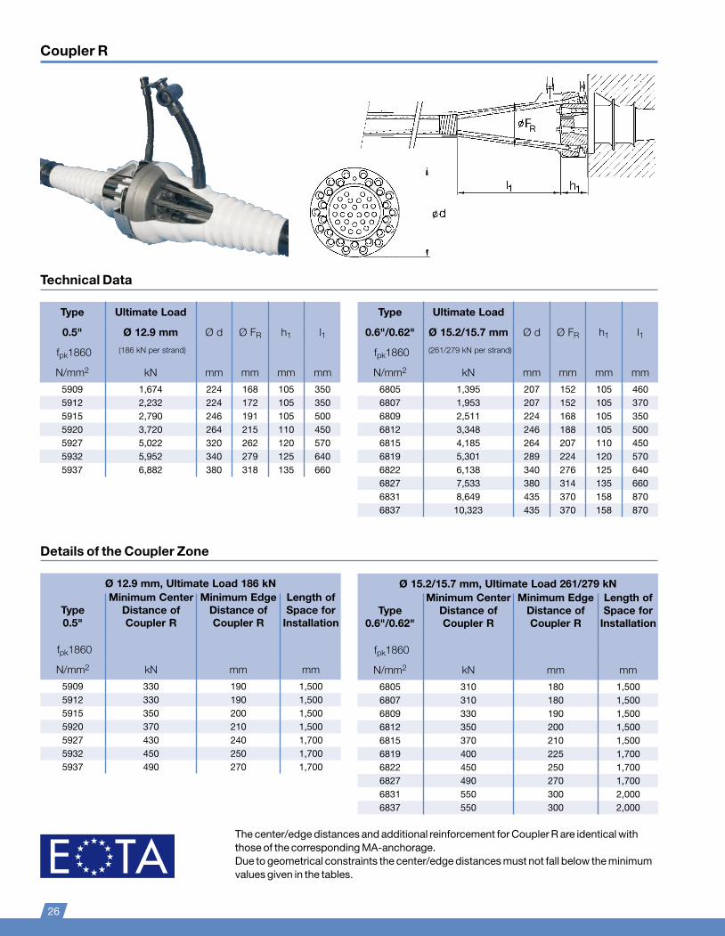
Technical Data
Details of the Coupler Zone
The center/edge distances and additional reinforcement for Coupler R are identical with those of the corresponding MA-anchorage. Due to geometrical constraints the center/edge distances must not fall below the minimum values given in the tables.
Coupler R
Type Ultimate Load
0.5" Ø 12.9 mm Ø d Ø FR h1 l1
fpk1860 (186 kN per strand)
N/mm2 kN mm mm mm mm
5909 1,674 224 168 105 3505912 2,232 224 172 105 3505915 2,790 246 191 105 5005920 3,720 264 215 110 4505927 5,022 320 262 120 5705932 5,952 340 279 125 6405937 6,882 380 318 135 660
Type Ultimate Load
0.6"/0.62" Ø 15.2/15.7 mm Ø d Ø FR h1 l1
fpk1860 (261/279 kN per strand)
N/mm2 kN mm mm mm mm
6805 1,395 207 152 105 4606807 1,953 207 152 105 3706809 2,511 224 168 105 3506812 3,348 246 188 105 5006815 4,185 264 207 110 4506819 5,301 289 224 120 5706822 6,138 340 276 125 6406827 7,533 380 314 135 6606831 8,649 435 370 158 8706837 10,323 435 370 158 870
Ø 12.9 mm, Ultimate Load 186 kN
Type 0.5"
Minimum Center Distance of Coupler R
Minimum Edge Distance of Coupler R
Length of Space for
Installation
fpk1860
N/mm2 kN mm mm
5909 330 190 1,5005912 330 190 1,5005915 350 200 1,5005920 370 210 1,5005927 430 240 1,7005932 450 250 1,7005937 490 270 1,700
Ø 15.2/15.7 mm, Ultimate Load 261/279 kN
Type 0.6"/0.62"
Minimum Center Distance of Coupler R
Minimum Edge Distance of Coupler R
Length of Space for
Installation
fpk1860
N/mm2 kN mm mm
6805 310 180 1,5006807 310 180 1,5006809 330 190 1,5006812 350 200 1,5006815 370 210 1,5006819 400 225 1,7006822 450 250 1,7006827 490 270 1,7006831 550 300 2,0006837 550 300 2,000
26
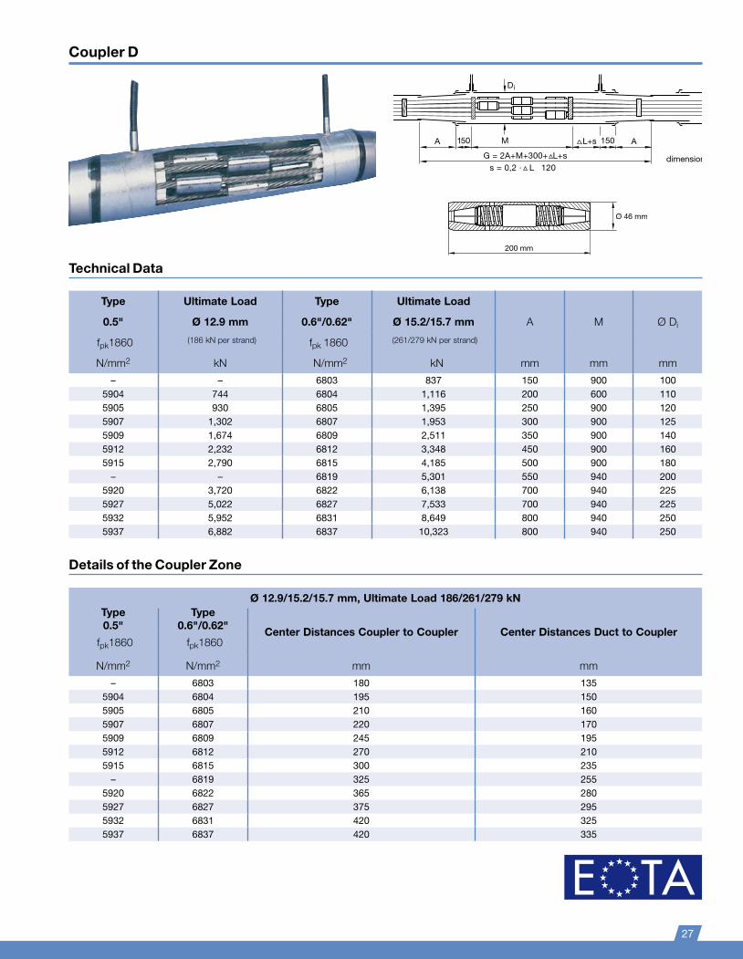
M150 L+sA A150
G = 2A+M+300+ L+ss = 0,2 · L 120
Di
dimensions in mm
200 mm
Ø 46 mm
Technical Data
Details of the Coupler Zone
Coupler D
Type Ultimate Load Type Ultimate Load
0.5" Ø 12.9 mm 0.6"/0.62" Ø 15.2/15.7 mm A M Ø Di
fpk1860 (186 kN per strand) fpk 1860 (261/279 kN per strand)
N/mm2 kN N/mm2 kN mm mm mm
– – 6803 837 150 900 1005904 744 6804 1,116 200 600 1105905 930 6805 1,395 250 900 1205907 1,302 6807 1,953 300 900 1255909 1,674 6809 2,511 350 900 1405912 2,232 6812 3,348 450 900 1605915 2,790 6815 4,185 500 900 180
– – 6819 5,301 550 940 2005920 3,720 6822 6,138 700 940 2255927 5,022 6827 7,533 700 940 2255932 5,952 6831 8,649 800 940 2505937 6,882 6837 10,323 800 940 250
Ø 12.9/15.2/15.7 mm, Ultimate Load 186/261/279 kNType 0.5"
Type 0.6"/0.62" Center Distances Coupler to Coupler Center Distances Duct to Coupler
fpk1860 fpk1860
N/mm2 N/mm2 mm mm
– 6803 180 1355904 6804 195 1505905 6805 210 1605907 6807 220 1705909 6809 245 1955912 6812 270 2105915 6815 300 235
– 6819 325 2555920 6822 365 2805927 6827 375 2955932 6831 420 3255937 6837 420 335
27
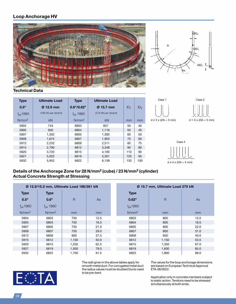
d ≥ 3 x (ØA + 5 mm)
Case 1
d = 4 x (ØA + 5 mm)
Case 2
d ≥ 4 x (ØA + 5 mm)
Case 3
R
As
ØID2
ØID1
ØID1
Technical Data
Details of the Anchorage Zone for 28 N/mm2 (cube) / 23 N/mm2 (cylinder) Actual Concrete Strength at Stressing
The radii given in the above tables apply for smooth metal duct. For corrugated metal duct the radius values must be doubled Ducts need to be pre-bent.
The values for the loop anchorage dimensions are based on European Technical Approval ETA-06/0022.
Application only in concrete members subject to static action. Tendons need to be stressed simultaneously at both ends.
Loop Anchorage HV
Type Ultimate Load Type Ultimate Load
0.5" Ø 12.9 mm 0.6"/0.62" Ø 15.7 mm ID1 ID2
fpk1860 (186 kN per strand) fpk 1860 (279 kN per strand)
N/mm2 kN N/mm2 kN mm mm
5904 744 6803 837 50 405905 930 6804 1,116 55 455907 1,302 6805 1,395 60 505909 1,674 6807 1,953 75 605912 2,232 6809 2,511 85 755915 2,790 6812 3,348 95 805920 3,720 6815 4,185 110 905927 5,022 6819 5,301 120 955932 5,952 6822 6,138 130 100
Ø 12.9/15.2 mm, Ultimate Load 186/261 kN
Type Type
0.5" 0.6" R As
fpk1860 fpk 1860
N/mm2 N/mm2 mm mm
5904 6803 750 12.55905 6804 750 16.55907 6805 750 21.05909 6807 750 29.05912 6809 900 37.55915 6812 1,100 50.05920 6815 1,250 62.55927 6819 1,500 79.05932 6822 1,700 91.5
Ø 15.7 mm, Ultimate Load 279 kN
Type
0.62" R As
fpk1860
N/mm2 mm mm
6803 800 13.56804 800 18.06805 800 22.06807 800 31.06809 950 40.06812 1,150 53.56815 1,350 67.06819 1,600 85.06822 1,800 98.0
28
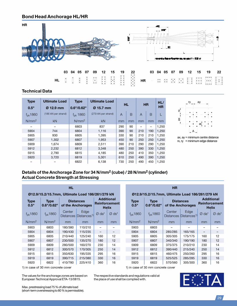
HR
Technical Data
Details of the Anchorage Zone for 34 N/mm2 (cube) / 28 N/mm2 (cylinder) Actual Concrete Strength at Stressing
The values for the anchorage zones are based on European Technical Approval ETA-13/0815.
Max. prestressing load 75 % of ultimate load (short-term overstressing to 80 % is permissible).
The respective standards and regulations valid at the place of use shall be complied with.
Bond Head Anchorage HL/HR
Type Ultimate Load Type Ultimate LoadHL HR HL/
HR0.5" Ø 12.9 mm 0.6"/0.62" Ø 15.7 mm
fpk1860 (186 kN per strand) fpk 1860 (279 kN per strand) A B A B L
N/mm2 kN N/mm2 kN mm mm mm mm mm
– – 6803 837 290 90 – – 1,2505904 744 6804 1,116 390 90 210 190 1,2505905 930 6805 1,395 330 90 210 210 1,2505907 1,302 6807 1,953 450 90 250 250 1,2505909 1,674 6809 2,511 390 210 290 290 1,2505912 2,232 6812 3,348 480 250 390 330 1,2505915 2,790 6815 4,185 480 250 410 350 1,2505920 3,720 6819 5,301 610 250 490 390 1,250
– – 6822 6,138 730 250 490 450 1,250
HL
Ø12.9/15.2/15.7mm, Ultimate Load 186/261/279 kN
Type 0.5"
Type 0.6"/0.62"
Distances of the Anchorages
Additional Reinforcement
Helix
fpk1860 fpk1860Center
DistancesEdge
Distances1) Ø da* Ø ds*
N/mm2 N/mm2 mm mm mm mm
5903 6803 180/380 110/210 – –5904 6804 190/430 115/235 – –5905 6805 210/440 125/240 160 125907 6807 230/500 135/270 180 125909 6809 280/500 160/270 230 145912 6812 300/570 170/305 250 145915 6815 350/630 195/335 295 165919 6819 390/715 215/380 330 165920 6822 410/780 225/410 360 16
1) in case of 30 mm concrete cover
HR
Ø12.9/15.2/15.7mm, Ultimate Load 186/261/279 kN
Type 0.5"
Type 0.6"/0.62"
Distances of the Anchorages
Additional Reinforcement
Helix
fpk1860 fpk1860Center
DistancesEdge
Distances1) Ø da* Ø ds*
N/mm2 N/mm2 mm mm mm mm
5903 6803 – – – –5904 6804 285/285 165/165 – –5905 6805 305/305 175/175 160 125907 6807 340/340 190/190 180 125909 6809 375/375 210/210 230 145912 6812 390/440 215/240 250 145915 6815 460/475 250/260 295 165919 6819 525/525 285/285 330 165920 6822 570/560 305/300 360 16
1) in case of 30 mm concrete cover
29
Technical Data
Details of Anchorage Zone
Max. prestressing load 70 % of ultimate load (short-term overstressing to 75 % is permissible). The respective standards and regulations valid at the place of use shall be complied with.
Coupler M
Coupler ME
Case 1: If LR ≤ L2-1/2 ∆L then L = s + 285 mm + L2
Case 2: If LR > L2-1/2 ∆L then L = s + 285 mm + L2 + 1/2 ∆L
s = 0.2 x 1/2 ∆L $ 120 mm
Block-Out Dimensions
Coupler M/ME (Floating Anchorage Block)
Type Ultimate Load Ultimate Load
0.6"/0.62" Ø 15.2 mm Ø 15.7 mm A B C D AD BD E
fpk1860 (261 kN per strand) (279 kN per strand)
N/mm2 kN kN mm mm mm mm mm mm mm
6801 261 279 98 55 200 20 – – –6802 522 558 90 105 120 40 60 70 2006804 1,043 1,116 130 160 120 55 70 130 6506806 1,564 1,674 130 160 120 65 70 130 6506808 2,086 2,232 130 210 120 75 70 170 1,0506810 2,607 2,790 168 210 120 80 100 170 1,1506812 3,129 3,348 168 210 120 80 100 170 1,150
Ø 15.2/15,7 mm, Ultimate Load 261/279 kN
Type
0.6"/0.62" X Y Z
fpk1860
N/mm2 mm mm mm
6801 100 180 606802 130 155 506804 180 195 706806 180 195 706808 230 195 706810 230 235 906812 230 235 90
Type
0.6"/0.62" L2 LR
fpk1860
N/mm2 mm mm
6801 – –6802 550 5506804 700 6006806 700 6006808 1,350 6006810 1,500 8006812 1,500 800
30
Technical Data
Max. prestressing load 75 % of ultimate load (short-term overstressing to 80 % is permissible). The values for the anchorage zones are based on requirements of FIP.
The respective standards and regulations valid at the place of use shall be complied with.
Details of the Anchorage Zone for 25 N/mm2 (cube) / 20 N/mm2 (cylinder) Actual Concrete Strength at Stressing
Flat Multiplane Anchorage FMA
Type Ultimate Load Type Ultimate Load
0.5" Ø 12.9 mm 0.6"/0.62" Ø 15.2/15.7 mm A B C D
fpk1860 (186 kN per strand) fpk 1860 (261/279 kN per strand)
N/mm2 kN N/mm2 kN mm mm mm mm
5903 558 6802 521 86 160 160 465905 930 6804 1,116 86 203 228 46
– – 6805 1,395 86 268 231 46
Ø12.9/15.7mm, Ultimate Load 186/265 kN
Type 0.5"
Distances of the anchorages
Additional Reinforcement Stirrups
fpk1860 Center Distance
min. slab thickness1) a x b n g
N/mm2 mm mm mm mm mm
5903 200 200 180/140 3 125905 320 200 230/140 3 12
1) in case of 30 mm concrete cover
Ø15.2/15.7mm, Ultimate Load 279 kN
Type 0.6"
Distances of the anchorages
Additional Reinforcement Stirrups
fpk1860 Center Distance
min. slab thickness1) a x b n g
N/mm2 mm mm mm mm mm
6802 200 200 160/140 3 126804 320 220 230/160 4 126805 400 220 310/160 4 12
1) in case of 30 mm concrete cover
31
L
D
L
D
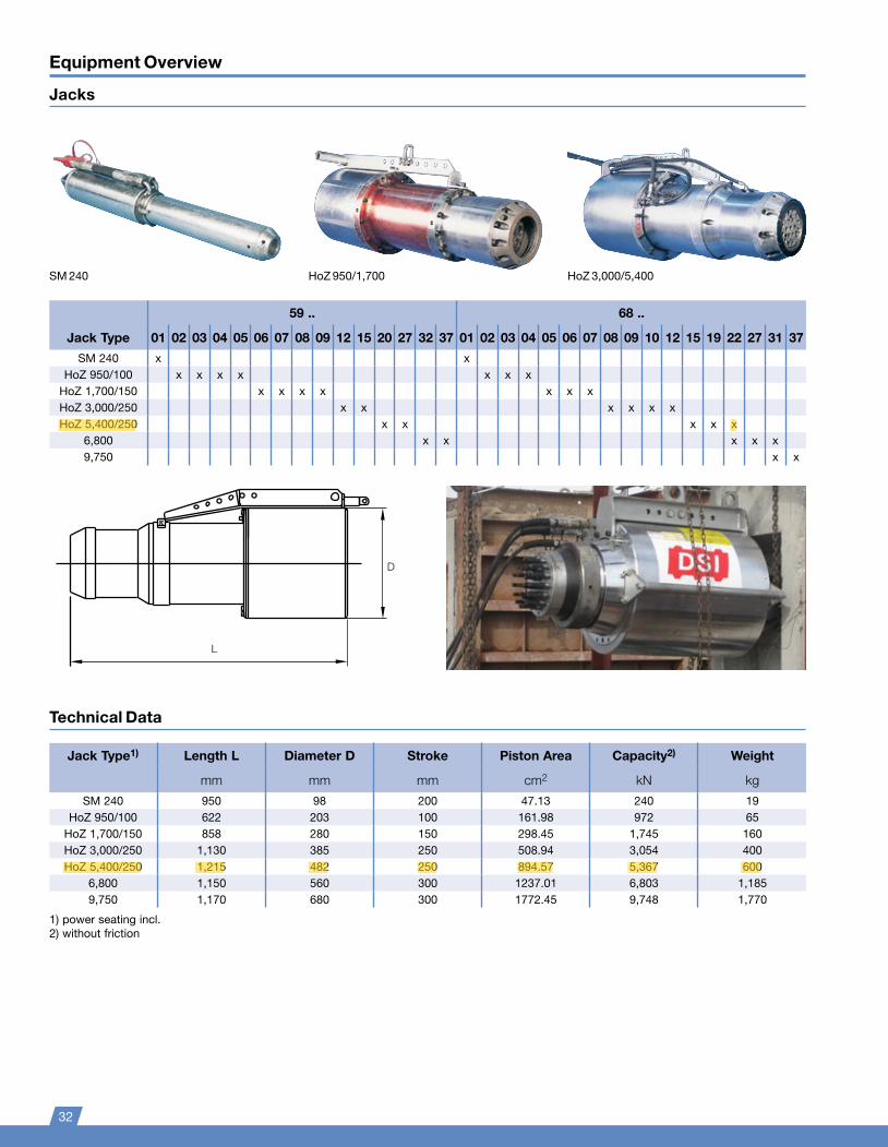
SM 240 HoZ 950/1,700 HoZ 3,000/5,400
Technical Data
Equipment Overview
Jacks
59 .. 68 ..
Jack Type 01 02 03 04 05 06 07 08 09 12 15 20 27 32 37 01 02 03 04 05 06 07 08 09 10 12 15 19 22 27 31 37
SM 240 x xHoZ 950/100 x x x x x x x
HoZ 1,700/150 x x x x x x xHoZ 3,000/250 x x x x x xHoZ 5,400/250 x x x x x
6,800 x x x x x9,750 x x
Jack Type1) Length L Diameter D Stroke Piston Area Capacity2) Weight
mm mm mm cm2 kN kg
SM 240 950 98 200 47.13 240 19HoZ 950/100 622 203 100 161.98 972 65
HoZ 1,700/150 858 280 150 298.45 1,745 160HoZ 3,000/250 1,130 385 250 508.94 3,054 400HoZ 5,400/250 1,215 482 250 894.57 5,367 600
6,800 1,150 560 300 1237.01 6,803 1,1859,750 1,170 680 300 1772.45 9,748 1,770
1) power seating incl. 2) without friction
32
G
K
A
B
C
FE
H
DD
B
A
CK
FE
G
H
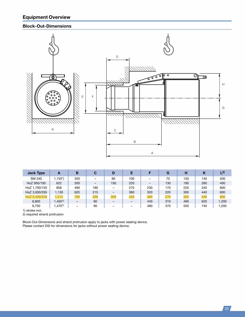
Equipment Overview
Block-Out-Dimensions
Jack Type A B C D E F G H K L2)
SM 240 1,1501) 350 – 80 100 – 70 150 140 500HoZ 950/100 622 350 – 150 220 – 130 190 260 400
HoZ 1,700/150 858 490 180 – 270 230 170 220 340 600HoZ 3,000/250 1,130 625 215 – 360 320 220 300 440 600HoZ 5,400/250 1,215 700 200 300 420 360 270 350 540 800
6,800 1,4501) – 80 – – 440 310 490 620 1,2009,750 1,4701) – 90 – – 480 370 550 740 1,200
1) stroke incl. 2) required strand protrusion
Block-Out-Dimensions and strand protrusion apply to jacks with power seating device.Please contact DSI for dimensions for jacks without power seating device.
33
R
ÿB
ÿA
As
ÿA
R
ÿB
ÿA
As
ÿA
R
ÿB
ÿA
As
ÿA
L
H
Width WWidth W
L
H
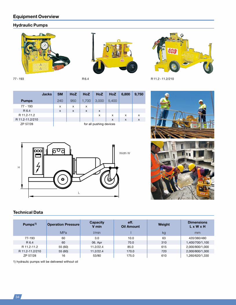
Technical Data
77 - 193 R 6.4 R 11.2 - 11.2/210
Equipment Overview
Hydraulic Pumps
Jacks SM HoZ HoZ HoZ HoZ 6,800 9,750
Pumps 240 950 1,700 3,000 5,400
77 - 193 x x xR 6.4 x x x x
R 11.2-11.2 x x x xR 11.2-11.2/210 x x x
ZP 57/28 for all pushing devices
Pumps1) Operation Pressure Capacity V min
eff. Oil Amount Weight Dimensions
L x W x H
MPa l/min I kg mm
77-193 60 3.0 10.0 63 420/380/480R 6.4 60 06. Apr 70.0 310 1,400/700/1,100
R 11.2-11.2 55 (60) 11.2/22.4 85.0 615 2,000/800/1,000R 11.2-11.2/210 55 (60) 11.2/22.4 170.0 720 2,000/800/1,300
ZP 57/28 16 53/80 175.0 610 1,260/620/1,330
1) hydraulic pumps will be delivered without oil
34
ESG 8 - 1
MP 2,000 - 5 MP 4,000 - 2 ZMP 712 V
Equipment Overview
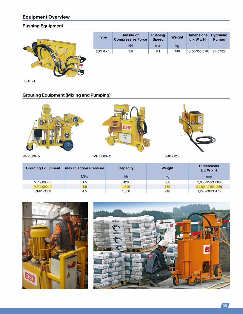
Pushing Equipment
Grouting Equipment (Mixing and Pumping)
Type Tensile or Compressive Force
Pushing Speed Weight Dimensions
L x W x HHydraulic
Pumps
kN m/s kg mm –
ESG 8 - 1 3.9 6.1 140 1,400/350/510 ZP 57/28
Grouting Equipment max Injection Pressure Capacity Weight Dimensions L x W x H
MPa l/h kg mm
MP 2,000 - 5 1.5 420 300 2,000/950/1,600MP 4,000 - 2 1.5 1,500 580 2,040/1,040/1,750ZMP 712 V 4.5 1,500 240 1,220/600/1,475
35
1
2
3
Po
Po
Pe
l c
l e
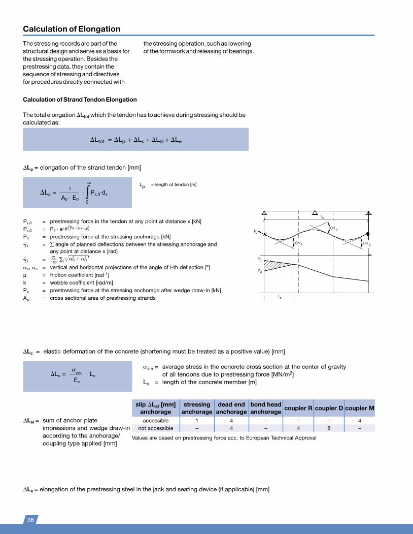
The stressing records are part of the structural design and serve as a basis for the stressing operation. Besides the prestressing data, they contain the sequence of stressing and directives for procedures directly connected with
Calculation of Strand Tendon Elongation
The total elongation DLtot which the tendon has to achieve during stressing should be calculated as:
DLp = elongation of the strand tendon [mm]
Px,0 = prestressing force in the tendon at any point at distance x [kN]Px,0 = P0 · e-µ(gX + k • Lp)
P0 = prestressing force at the stressing anchorage [kN]gx = ∑ angle of planned deflections between the stressing anchorage and
any point at distance x [rad]
gx = π 180 SiSwww '
aVi, aHi = vertical and horizontal projections of the angle of i-th deflection [°]µ = friction coefficient [rad-1]k = wobble coefficient [rad/m]Pe = prestressing force at the stressing anchorage after wedge draw-in [kN]Ap = cross sectional area of prestressing strands
DLc = elastic deformation of the concrete (shortening must be treated as a positive value) [mm]
scm
Ec
DLc = · Lc
DLsl = sum of anchor plate impressions and wedge draw-in according to the anchorage/ coupling type applied [mm]
DLp = · ∫ Px,0·dx
Lp = length of tendon [m]
the stressing operation, such as lowering of the formwork and releasing of bearings.
scm = average stress in the concrete cross section at the center of gravity of all tendons due to prestressing force [MN/m2]
Lc = length of the concrete member [m]
DLtot = DLp + DLc + DLsl + DLe
1
Ap · Ep
Lp
0
DLe = elongation of the prestressing steel in the jack and seating device (if applicable) [mm]
X
XX
aVi2 + aHi
2
Calculation of Elongation
slip DLsl [mm] anchorage
stressing anchorage
dead end anchorage
bond head anchorage coupler R coupler D coupler M
accessible 1 4 – – – 4not accessible – 4 – 4 8 –
Values are based on prestressing force acc. to European Technical Approval
36
Calculation of Prestressing Force Pe [kN] at Stressing Anchorage and Influence Length Le [m]
due to wedge draw-in DLn [mm] at stressing anchorage during lock-off of tensioning jack
Le = !www' DLn · Ep · Ap
P0 · µ · g1
X
Pe = P0 · (1 - 2 · Le· µ · g1)
g1 = average angle of deflection along the influence length Le of tendon behind the stressing anchorage [rad/m]
X
modulus of elasticity [N/mm2]
X
Calculation of Elongation
draw-in slip DLn [mm] tendon type jack type
standard case special case
at the stressing anchorage 6803 - 6837 3* 6**at the coupler M 6802 - 6812 8 –
values are based on prestressing force acc. to European Technical Approval*) with wedge seating **) without wedge seating
concrete class C 20/25 C 30/37 C 40/50 C 50/60
Ecm 29 32 35 37
strand Ep = 195,000 [N/mm2]
37
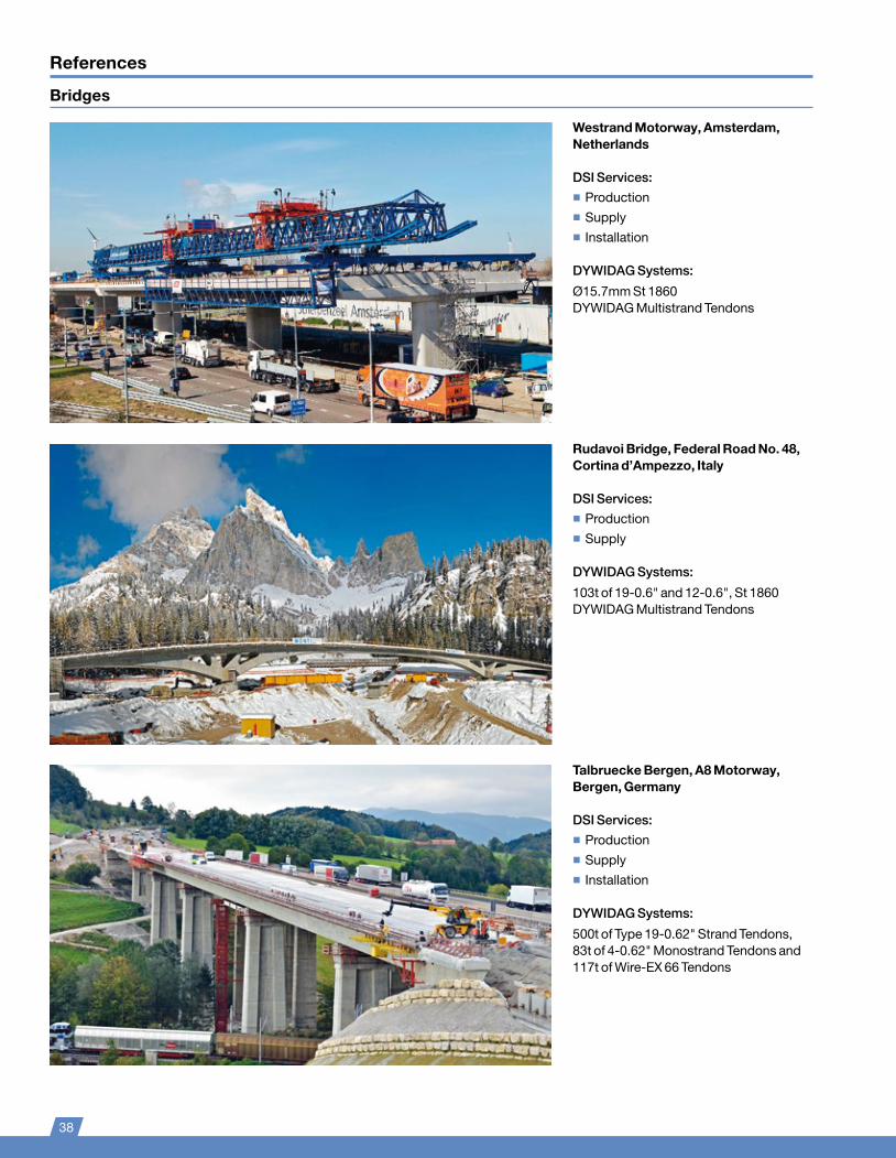
Bridges
Westrand Motorway, Amsterdam, Netherlands
DSI Services: ■ Production ■ Supply ■ Installation
DYWIDAG Systems:
Ø15.7mm St 1860 DYWIDAG Multistrand Tendons
Rudavoi Bridge, Federal Road No. 48, Cortina d’Ampezzo, Italy
DSI Services: ■ Production ■ Supply
DYWIDAG Systems:
103t of 19-0.6" and 12-0.6", St 1860 DYWIDAG Multistrand Tendons
Talbruecke Bergen, A8 Motorway, Bergen, Germany
DSI Services: ■ Production ■ Supply ■ Installation
DYWIDAG Systems:
500t of Type 19-0.62" Strand Tendons, 83t of 4-0.62" Monostrand Tendons and 117t of Wire-EX 66 Tendons
References
38
Jurong East Modification Project, Singapore
DSI Services: ■ Production ■ Supply ■ Installation
DYWIDAG Systems:
Type 7-0.6", 12-0.6", 19-0.6" and 22-0.6" DYWIDAG Multistrand Tendons with MA Anchorages as well as Ø47mm DYWIDAG Bars
Kyogbu High Speed Railway, Kimcheon, South Korea
DSI Services: ■ Production ■ Supply ■ Technical Support
DYWIDAG Systems:
3,168 internal and 1,464 external MA Anchorages Type 22-0.6"; rental of equipment
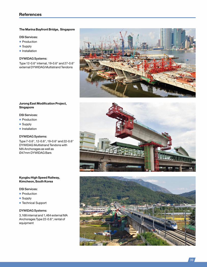
The Marina Bayfront Bridge, Singapore
DSI Services: ■ Production ■ Supply ■ Installation
DYWIDAG Systems:
Type 12-0.6" internal, 19-0.6" and 27-0.6" external DYWIDAG Multistrand Tendons
References
39
St. Anthony Falls Bridge, Minneapolis, Maine, USA
DSI Services: ■ Production ■ Supply ■ Installation ■ Engineering Services
DYWIDAG Systems:
Supply of 1,300km 0.6" 270k strand tendons; 4,100 Anchorages; 9,000m GEWI® Bars and hardware for formwork 57,000m 63 mm GEWI® Bars with hardware for reinforcement Post-Tensioning installation, stressing, and grouting equipment
The Canada Lin, Vancouver/Richmond, British Columbia, Canada
DSI Services: ■ Production ■ Supply
DYWIDAG Systems:
Supply of 374 type 27-0,6", 2.294 type 19-0,6" and 421 type 12-0,6" anchorages and duct; rental of equipment
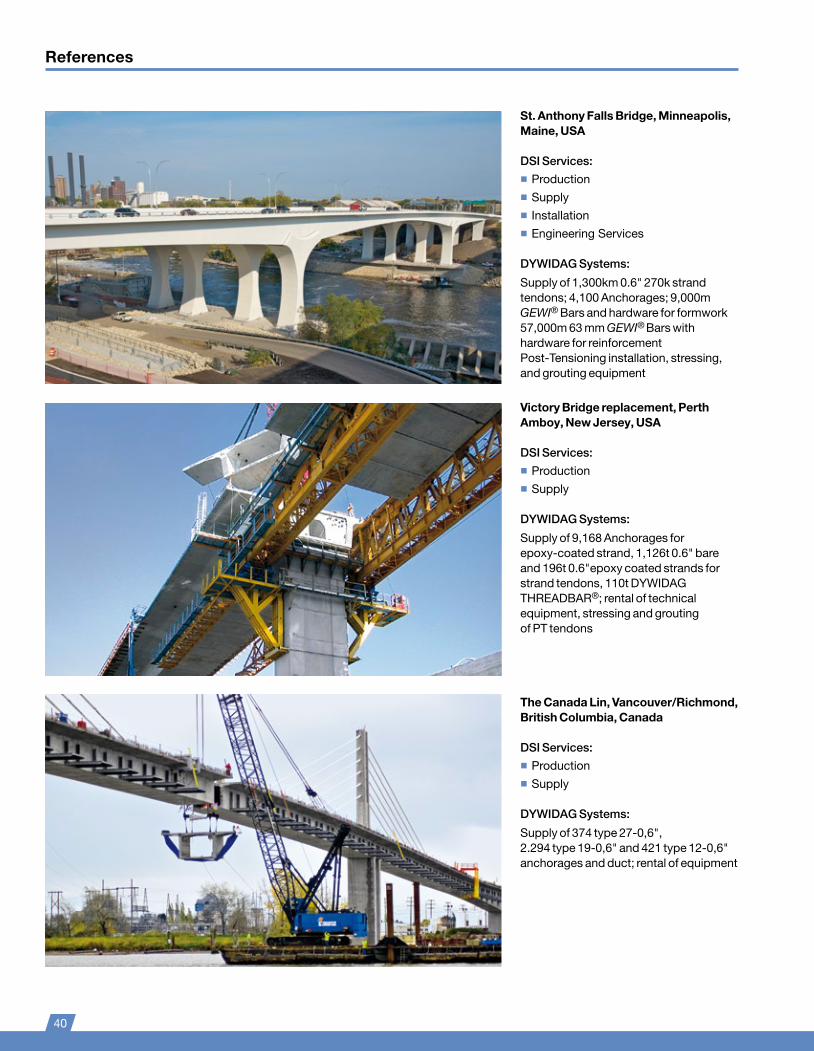
Victory Bridge replacement, Perth Amboy, New Jersey, USA
DSI Services: ■ Production ■ Supply
DYWIDAG Systems:
Supply of 9,168 Anchorages for epoxy-coated strand, 1,126t 0.6" bare and 196t 0.6"epoxy coated strands for strand tendons, 110t DYWIDAG THREADBAR®; rental of technical equipment, stressing and grouting of PT tendons
References
40
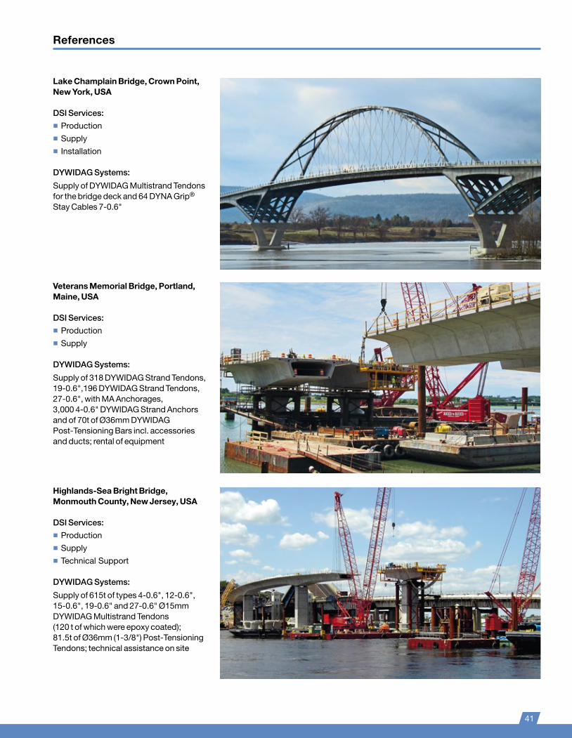
Lake Champlain Bridge, Crown Point, New York, USA
DSI Services: ■ Production ■ Supply ■ Installation
DYWIDAG Systems:
Supply of DYWIDAG Multistrand Tendons for the bridge deck and 64 DYNA Grip® Stay Cables 7-0.6"
Highlands-Sea Bright Bridge, Monmouth County, New Jersey, USA
DSI Services: ■ Production ■ Supply ■ Technical Support
DYWIDAG Systems:
Supply of 615t of types 4-0.6", 12-0.6", 15-0.6", 19-0.6" and 27-0.6" Ø15mm DYWIDAG Multistrand Tendons (120 t of which were epoxy coated); 81.5t of Ø36mm (1-3/8") Post-Tensioning Tendons; technical assistance on site
Veterans Memorial Bridge, Portland, Maine, USA
DSI Services: ■ Production ■ Supply
DYWIDAG Systems:
Supply of 318 DYWIDAG Strand Tendons, 19-0.6",196 DYWIDAG Strand Tendons, 27-0.6", with MA Anchorages, 3,000 4-0.6" DYWIDAG Strand Anchors and of 70t of Ø36mm DYWIDAG Post-Tensioning Bars incl. accessories and ducts; rental of equipment
References
41
Commercial Buildings
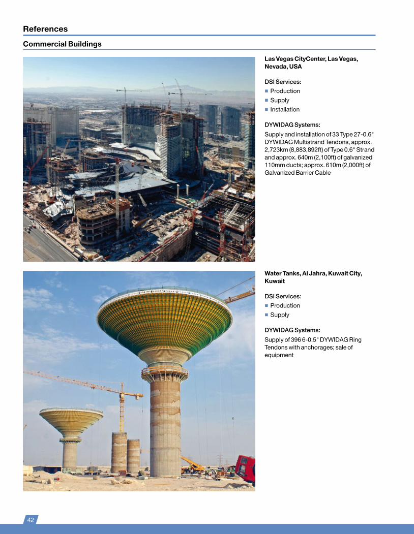
Las Vegas CityCenter, Las Vegas, Nevada, USA
DSI Services: ■ Production ■ Supply ■ Installation
DYWIDAG Systems:
Supply and installation of 33 Type 27-0.6" DYWIDAG Multistrand Tendons, approx. 2,723km (8,883,892ft) of Type 0.6" Strand and approx. 640m (2,100ft) of galvanized 110mm ducts; approx. 610m (2,000ft) of Galvanized Barrier Cable
Water Tanks, Al Jahra, Kuwait City, Kuwait
DSI Services: ■ Production ■ Supply
DYWIDAG Systems:
Supply of 396 6-0.5" DYWIDAG Ring Tendons with anchorages; sale of equipment
References
42
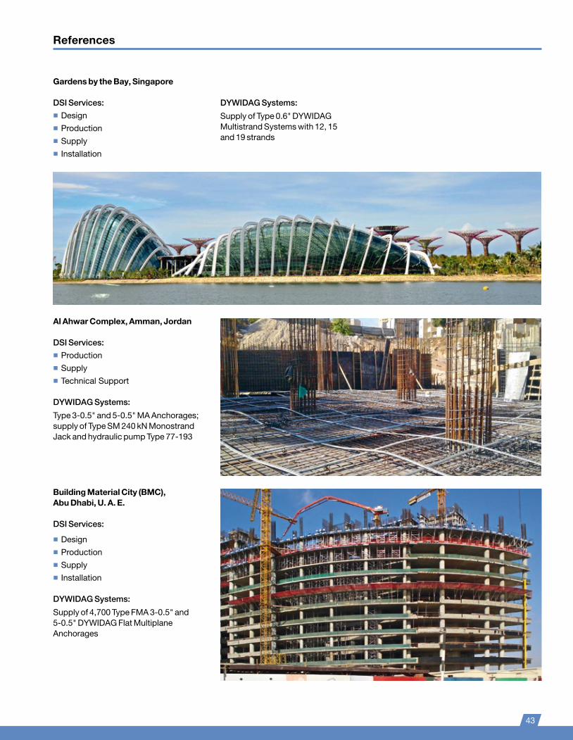
Gardens by the Bay, Singapore
DSI Services: ■ Design ■ Production ■ Supply ■ Installation
DYWIDAG Systems:
Supply of Type 0.6" DYWIDAG Multistrand Systems with 12, 15 and 19 strands
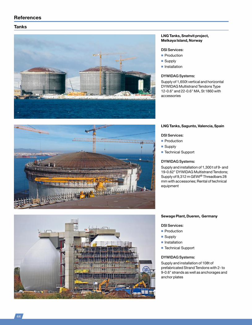
Al Ahwar Complex, Amman, Jordan
DSI Services: ■ Production ■ Supply ■ Technical Support
DYWIDAG Systems:
Type 3-0.5" and 5-0.5" MA Anchorages; supply of Type SM 240 kN Monostrand Jack and hydraulic pump Type 77-193
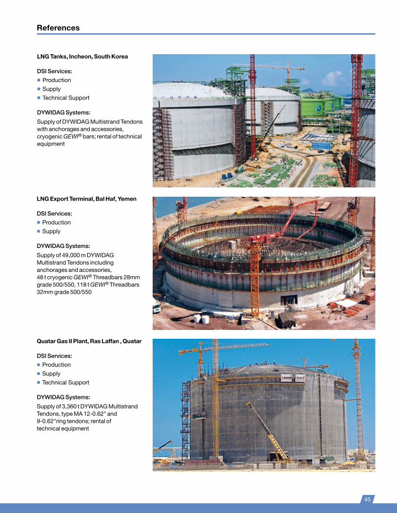
Building Material City (BMC), Abu Dhabi, U. A. E.
DSI Services:
■ Design ■ Production ■ Supply ■ Installation
DYWIDAG Systems:
Supply of 4,700 Type FMA 3-0.5" and 5-0.5" DYWIDAG Flat Multiplane Anchorages
References
43
Tanks
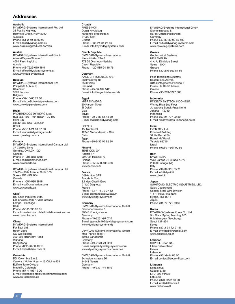
LNG Tanks, Snøhvit project, Melkøya Island, Norway
DSI Services: ■ Production ■ Supply ■ Installation
DYWIDAG Systems:
Supply of 1,650t vertical and horizontal DYWIDAG Multistrand Tendons Type 12-0.6" and 22-0.6" MA, St 1860 with accessories
LNG Tanks, Sagunto, Valencia, Spain
DSI Services: ■ Production ■ Supply ■ Technical Support
DYWIDAG Systems:
Supply and installation of 1,300 t of 9- and 19-0.62" DYWIDAG Multistrand Tendons; Supply of 9,312 m GEWI® Threadbars 28 mm with accessories; Rental of technical equipment
Sewage Plant, Dueren, Germany
DSI Services: ■ Production ■ Supply ■ Installation ■ Technical Support
DYWIDAG Systems:
Supply and installation of 108t of prefabricated Strand Tendons with 2- to 9-0.6" strands as well as anchorages and anchor plates
References
44
LNG Export Terminal, Bal Haf, Yemen
DSI Services: ■ Production ■ Supply
DYWIDAG Systems:
Supply of 49,000 m DYWIDAG Multistrand Tendons including anchorages and accessories, 48 t cryogenic GEWI® Threadbars 28mm grade 500/550, 118 t GEWI® Threadbars 32mm grade 500/550
Quatar Gas II Plant, Ras Laffan , Quatar
DSI Services: ■ Production ■ Supply ■ Technical Support
DYWIDAG Systems:
Supply of 3,360 t DYWIDAG Multistrand Tendons, type MA 12-0.62" and 9-0.62"ring tendons; rental of technical equipment
LNG Tanks, Incheon, South Korea
DSI Services: ■ Production ■ Supply ■ Technical Support
DYWIDAG Systems:
Supply of DYWIDAG Multistrand Tendons with anchorages and accessories, cryogenic GEWI® bars; rental of technical equipment
References
45
AustraliaDYWIDAG-Systems International Pty. Ltd.25 Pacific HighwayBennetts Green, NSW 2290AustraliaPhone +61-2-49 48 90 99E-mail [email protected]/au
AustriaDYWIDAG-Systems International GmbHAlfred-Wagner-Strasse 14061 Pasching/LinzAustriaPhone +43-7229-610 49 0E-mail [email protected]
BelgiumDYWIDAG-Systems International N.V.Philipssite 5, bus 15Ubicenter3001 LeuvenBelgiumPhone +32-16-60 77 60E-mail [email protected]
BrazilPROTENDIDOS DYWIDAG Ltda.Rua Iaiá, 150 – 10° andar – Cj. 102Itaim Bibi04542-060-São Paulo/SPBrazilPhone +55-11-21 31 37 00E-mail [email protected]
CanadaDYWIDAG-Systems International Canada Ltd.37 Cardico DriveGormley, ON L0H-1G0CanadaPhone +1-905-888 8988E-mail [email protected]
DYWIDAG-Systems International Canada Ltd.19433 – 96th Avenue, Suite 103Surrey, BC V4N 4C4CanadaPhone +1-604-888 8818E-mail [email protected]
ChileDSI Chile Industrial Ltda.Las Encinas #1387, Valle GrandeLampa – SantiagoChilePhone +56-2-596 96 61E-mail [email protected]
ChinaDYWIDAG-Systems InternationalFar East Ltd.Room 2306CC Wu Building302-308 Hennessy RoadWanchaiHong KongPhone +852-28-33 19 13E-mail [email protected]
ColombiaDSI Colombia S.A.S.Carrera 43A No. 8 sur – 15 Oficina 403Edificio Torre OviedoMedellín, ColombiaPhone +57-4-403 12 00E-mail [email protected]
CroatiaPRESS-KONObala Hrvatskognarodnog preporoda 621000 SplitCroatiaPhone +385-21-34 27 66E-mail [email protected]
Czech RepublicDYWIDAG-Systems InternationalJilemnického 29/46772 00 Olomouc-NedvěziCzech RepublicPhone +420-585-94 10 76
DenmarkAAGE CHRISTENSEN A/SSkelmosevej 102500 ValbyDenmarkPhone +45-36-132 542E-mail [email protected]
EgyptMISR DYWIDAG20 Haroun StreetEl DokkiGizaEgyptPhone +20-2-37 61 48 69E-mail [email protected]
SPENSY15, Nables St.12345 Mohandessin – GizaCairoEgyptPhone +20-2-33 05 82 20
FinlandTENSICON OYRattitie 17007700, Helsinki 77FinlandPhone +358-500-406 438www.tensicon.fi
FranceDSI-Artéon SASRue de la CrazZ.I. des Chartinières01120 DagneuxFrancePhone +33-4-78 79 27 82E-mail [email protected]
GermanyDYWIDAG-Systems International GmbHGermanenstrasse 886343 KoenigsbrunnGermanyPhone +49-8231-96 07 0E-mail [email protected]
DYWIDAG-Systems International GmbHMax-Planck-Ring 140764 LangenfeldGermanyPhone +49-2173-79 02 0E-mail [email protected]/emea
DYWIDAG-Systems International GmbHSchuetzenstrasse 2014641 NauenGermanyPhone +49-3321-44 18 0
DYWIDAG-Systems International GmbHSiemensstrasse 885716 UnterschleissheimGermanyPhone +49-89-30 90 50 100E-mail [email protected]
GreeceGeotechnical SystemsHELLENPLAN4 K. A. Dimitriou StreetSpata 19004GreecePhone +30-210-663 57 86
Post-Tensioning SystemsKostantinos Zervas34th Sintagmatos Pezikon 5Pireas TK 18532 AthensGreecePhone +30-213-0227 363
IndonesiaPT DELTA SYSTECH INDONESIAWisma Ritra 2nd FloorJl. Warung Buncit Raya No. 6Jakarta – 12740IndonesiaPhone +62-21-797 02 89E-mail [email protected]
IsraelEVEN GEV Ltd.Emanuel Building31 Ha’Barzel Str.Ramat Ha’HayalTel Aviv 69710IsraelPhone +972-77-501 00 56
ItalyDYWIT S.P.A.Viale Europa 72 Strada A 7/920090 Cusago (MI)ItalyPhone +39-02-901 65 71E-mail [email protected]
JapanSUMITOMO ELECTRIC INDUSTRIES, LTD.Sales DepartmentSpecial Steel Wire Division1-1-1, Koya-kita Itami,Hyogo, 664-0016JapanPhone +81-72-771-0966
KoreaDYWIDAG-Systems Korea Co. Ltd.5th Floor, Spring Morning B/D8, Mabang-ro, Seocho-guSeoul 137-894KoreaPhone +82-2-34 72 01 41E-mail [email protected]
LebanonSOPREL Liban SALLiban Cable StreetHalateLebanonPhone +961-9-44 88 60E-mail [email protected]
LithuaniaDelta NovaUžupio g. 30LT-01203 VilniusLithuaniaPhone +370-5272-53 08E-mail [email protected]
Addresses
46
MexicoDS International México, S.A. de C.V.Av. Aviación No 1002 Bod. 15Parque Industrial FERRAN ISan Juan de OcotánZapopan, Jalisco 45019MéxicoPhone +52-33-33 66 57 94E-mail [email protected]
NetherlandsDYWIDAG-Systems International B.V.Veilingweg 25301 KM ZaltbommelNetherlandsPhone +31-418-57 89 22E-mail [email protected]
NigeriaPTSL Post Tensioning Services Limited167C Isale Eko AvDolphin EstateIkoyi, LagosNigeriaPhone +234-80-72 72 22 22E-mail [email protected]
NorwayDywidag Norge ASNorvald Strands veg 212206 KongsvingerNorwayPhone +47-67-06 15 60E-mail [email protected]
PeruDSI Peru S.A.C.Calle Uno Oeste 0061 Of. 103San Isidro-Lima 1 / PeruPhone +51-1-224 54 54E-mail [email protected]
PolandDYWIDAG-Systems International Sp. z o.o.ul. Bojowników o Wolnos´ c´ i Demokracje, 38/12141-506 ChorzówPolandPhone +48-32-241 09 98E-mail [email protected]
PortugalDYWIDAG SISTEMAS CONSTRUCTIVOS, SARua D. Manuel, n.º 24 AQuinta da Parreirinha2695-003 Bobadela (Loures)PortugalPhone +351-21-892 28 90E-mail [email protected]
QatarQACS (Qatar Australien Construction Systems W.L.L.)Al ThumamaStreet No 911, Villa No 56, Area No 46 E Ring road, Near to ElectricDoha / QatarPhone +974-44-58 04 11
RussiaDSI-PSK OOOJoint VentureLeninsky prospekt,d. 105, korp. 4Moscow 119421RussiaPhone +7-495-234 25 02www.psk-holding.ru
Saudi ArabiaDYWIDAG-Systems International „DSI“, RiyadhP.O. Box 53039,Riyadh, 11583Saudi ArabiaPhone +966-1-46 50 311 ext. 106
BIC Prestressed ConcreteP.O. Box 101688,Riyadh, 11665Saudi ArabiaPhone +966-1-278 14 79E-mail [email protected]
Serbia & MontenegroEnCon d.o.o.3, Cara Lazara Street11000 BelgradeSerbia & MontenegroPhone +381-11-328 12 73
SingaporeUTRACON STRUCTURAL SYSTEMS PTE LTD7 E Pioneer Sector 1Singapore 628446Phone +65-64-15 30 78E-mail [email protected]
SlovakiaDoprastav, a.s.Závod PrefaDrienˇ ová 31821 01 BratislavaSlovakiaPhone +421-2-48 271 130
South AfricaAmsteele SystemsUnit 20, Lothlorien Industrial ParkTedstone Road, WadevilleAlbemarle 1410South AfricaPhone +27-11-827 6721
SpainDYWIDAG SISTEMAS CONSTRUCTIVOS, S.A.Avd/de la Industria, 4Pol. Ind. la Cantuena28947 Fuenlabrada (Madrid)SpainPhone +34-91-642 20 72E-mail [email protected]
SwitzerlandSpannStahl AGIndustriegebietWaesseristrasse 298340 Hinwil/ZHSwitzerlandPhone +41-44-9 38 97 97E-mail [email protected]
TaiwanDYWITECH Co. Ltd.13th Fl.-3, No. 163, Sec. 1, Keelung RoadTaipei 110Taiwan, R.O.C.Phone +886-2-27 48 10 76
ThailandD-Tech Postten Co., Ltd.91/22 Suwinthawong roadMinburi district, MinburiBangkok 10510ThailandPhone +66-2543-77 61
TurkeyDIVIGER Yapi Teknoloji A.S.Yildiz Posta Cad.Ayildiz Sitesi 30/1534349 Istanbul-GayrettepeTurkeyPhone +90-212-234 56 12E-mail [email protected]
United KingdomDYWIDAG-Systems International Ltd.Northfield RoadSoutham, Warwickshire, CV47 0FGGreat BritainPhone +44-1926-81 39 80E-mail [email protected]
USADYWIDAG-Systems International USA Inc.320 Marmon DriveBolingbrook, IL 60440USAPhone +1-630-739 1100E-mail [email protected]
DYWIDAG-Systems International USA Inc.2154 South StreetLong Beach, CA 90805USAPhone +1-562-531 6161E-mail [email protected]
Addresses
47
Please Note: This brochure serves basic informationpurposes only. Technical data and informationprovided herein shall be considerednon-binding and may be subject to changewithout notice. We do not assume any liabilityfor losses or damages attributed to the useof this technical data and any improperuse of our products. Should you requirefurther information on particular products,please do not hesitate to contact us.
North AmericaDYWIDAG-Systems International USA Inc.320 Marmon DriveBolingbrook, IL 60440USAPhone +1-630-7 39 11 00E-mail [email protected]
South AmericaPROTENDIDOS DYWIDAG Ltda.Rua Iaiá, 150 – 10° andar - Cj.102Itaim Bibi04542-060-São Paulo/SPBrazilPhone +55-11-21 31 37 00E-mail [email protected]
EMEADYWIDAG-Systems International GmbHMax-Planck-Ring 140764 LangenfeldGermanyPhone +49-2173-79 02 0E-mail [email protected]/emea
APACDYWIDAG-Systems International Pty. Ltd.25 Pacific HighwayBennetts Green, NSW 2290AustraliaPhone +61-2-49 48 90 99E-mail [email protected]/au
0416
0-1/
02.1
4-30
0 sc
ho
A R G E N T I N A
A U S T R A L I A
A U S T R I A
B E L G I U M
B O S N I A A N D H E R Z E G O V I N A
B R A Z I L
C A N A D A
C H I L E
C H I N A
C O L O M B I A
C O S T A R I C A
C R O A T I A
C Z E C H R E P U B L I C
D E N M A R K
E G Y P T
E S T O N I A
F I N L A N D
F R A N C E
G E R M A N Y
G R E E C E
G U A T E M A L A
H O N D U R A S
H O N G K O N G
I N D O N E S I A
I T A L Y
J A P A N
K O R E A
L E B A N O N
L U X E M B O U R G
M A L A Y S I A
M E X I C O
N E T H E R L A N D S
N O R W A Y
O M A N
P A N A M A
P A R A G U A Y
P E R U
P O L A N D
P O R T U G A L
Q A T A R
R U S S I A
S A U D I A R A B I A
S I N G A P O R E
S O U T H A F R I C A
S P A I N
S W E D E N
S W I T Z E R L A N D
T A I W A N
T H A I L A N D
T U R K E Y
U N I T E D A R A B E M I R A T E S
U N I T E D K I N G D O M
U R U G U A Y
U S A
V E N E Z U E L A
www.dywidag-systems.com/emea
Recommended


![Post Tensioning[1]](https://img.dokumen.tips/doc/110x75/543ffc0bafaf9fff098b4bcd/post-tensioning1.jpg)