Front and Inside Cover Photos Courtesy ofOdfjell Seachem, Bergen, Norway
Back Cover Photo Courtesy ofM.T. Maritime of Westport, Connecticut USA

TANK CLEANING MANUALFIFTH EDITION
®Registered trademark, TMTrademark of Ashland Inc.*Registered service mark of the American Chemistry Council, the Canadian Chemical
Producers' Association and of other entities in other countries.©2002, 2005 Ashland Inc. All Rights Reserved. • TM-TC-1
www.drew-marine.com
All statements, information and data presented herein are believed to be accurate and reliable but are not to be taken as a guarantee, express warranty or implied warranty of merchantability or fitnessfor a particular purpose, or representation, express or implied, for which seller assumes legal responsibility, and they are offered solely for your consideration, investigation and verification. Statementsor suggestions concerning possible use of this product are made without representation or warranty that any such use is free of patent infringement and are not recommendations to infringe on any patent.
DREW MARINE • One Drew Plaza, Boonton, NJ 07005 USA • Tel: (1-973) 263-7600 • Fax: (1-973) 263-4491
Ashland is committed to the continuous evolution oftechnology and service solutions that promote health,safety and environmental protection around the world.

- 1 -
INTRODUCTION
The information and facts contained in this manual have been researched and correlated employing chemists,industry experts and various users of tank cleaning chemicals. However, the information should not be construedas a definitive warranty for the guaranteeing of any specific tank cleaning process, especially during times ofexceptional conditions or circumstances.
Tank cleaning, in general, is an expensive activity. However, the washing of tanks using chemicals is often a greataid to minimizing cleaning costs and achieving the desired degree of residue control.
The aim of each tank cleaning operation is to render every tank or hold suitable for immediate commencement ofloading cargo or performing repairs available in the most efficient manner possible. This tank cleaning should beaccomplished with the optimum combination of cost, time and manpower. In addition, ensuring that the environmentremains uncontaminated by pollutants. The degree and extent of the type of cleaning required depends upon theexact nature of the product to be loaded and upon the characteristics of the cargoes which were previously carried,especially the last cargo. If the cargo to be loaded is of a similar nature to the cargo immediately discharged, thencleaning work is usually minimal. The type of cleaning chemical selected will also depend upon whether or not thetank has been coated.
Very often it is necessary to prepare the holds or tanks of a vessel to receive an entirely different cargo. This canoften only be achieved in the time available by using a carefully selected chemical cleaning process which will aidthe rapid and complete removal of tenacious residues and sediments.
Indispensable to the efficient cleaning of tanks is a clear understanding of the nature of the problems and theproducts involved. The essence, therefore, of good tank cleaning is to use the correct mechanical equipment withproperly selected cleaning chemicals applied in the approved fashion for the type of residues to be removed andthe cargo to be received.
- 2 -
CHAPTER I
TANK CLEANING SYSTEM COMPONENTS
The tank cleaning system often consists of the following components:
• Water supply pump• Deck water supply distribution piping• Tank cleaning water heater• Deck access openings for portable machines• Tank washing machines• Stripping pumps or eductors
1. ASSOCIATED EQUIPMENT
• Quadrant saddles• Wash hoses• Couplings for hoses• Air hoses• Scrapers• Mucking winches• Brooms• Squeegee mops• Cargo clusters and lights (vapor proof)• Torches (flashlights) (vapor proof)• Spanners (spark proof)• Oil absorbent material• Rags
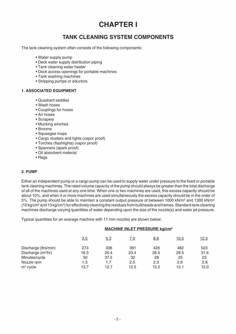
2. PUMP
Either an independent pump or a cargo pump can be used to supply water under pressure to the fixed or portabletank cleaning machines. The rated volume capacity of the pump should always be greater than the total dischargeof all of the machines used at any one time. When one or two machines are used, this excess capacity should beabout 10%, and when 4 or more machines are used simultaneously the excess capacity should be in the order of5%. The pump should be able to maintain a constant output pressure of between 1000 kN/m2 and 1300 kN/m2
(10 kg/cm2 and 13 kg/cm2) for effectively cleaning the residues from bulkheads and frames. Standard tank cleaningmachines discharge varying quantities of water depending upon the size of the nozzle(s) and water jet pressure.
Typical quantities for an average machine with 11 mm nozzles are shown below:
MACHINE INLET PRESSURE kg/cm2
3.5 5.3 7.0 8.8 10.5 12.3
Discharge (ltrs/min) 273 336 391 426 482 523Discharge (m3/hr) 16.3 20.4 23.4 26.5 28.5 31.6Minutes/cycle 50 37.5 32 28 25 23Nozzle rpm 1.3 1.7 2.0 2.3 2.6 2.8m3 cycle 13.7 12.7 12.5 12.2 12.1 12.0

- 3 -
B
C
A
175 PSIG75 100 125 1503.5 12.3 kg/cm5.3 7.0 8.8 10.5 2
Ton
s/H
our
Lite
rs P
.M.
G.P
.M.
Pressure at Machine Inlet
Type "SK" A: .562" Tips [9/16"]Type "K" [Marine] B: .437" Tips [7/16"]Type "K" [Shore] C: .375" Tips [3/8"]
Figure 1 Figure 2 BUTTERWORTH TYPE "K" and TYPE "SK" BUTTERWORTH TYPE "K" AND TYPE "SK" TANK CLEANING MACHINES TANK CLEANING MACHINES
Diagrammatically the BUTTERWORTH K and SK/SSK machines can be represented as shown below:
Figure 3 Figure 4 K MACHINE SK and SSK MACHINE
Graphically shown below are the average discharge rates for various size nozzles at different pressures as wellas the cycle times for BUTTERWORTH1 K and SK tank cleaning machines.
Type "SK" A: .562" Tips [9/16"]Type "K" [Marine] B: .437" Tips [7/16"]Type "K" [Shore] C: .375" Tips [3/8"]
40
50
20
30
10Tim
e fo
r O
ne
Cyc
le -
Min
s.
B
A
C
50 75 100 125 1503.5 12.3 kg/cm5.3 7.0 8.8 10.5 2
Pressure at Machine Inlet
0
228
216
72
192
168
144
120
96
4850
863
636
455
364
182
818
727
546
273
38.2
27.3
21.9
10.9
49.0
43.7
32.0
16.4
51.8
Dis
char
ge
Rat
e
175 PSIG

- 4 -
Figure 5
ARRANGEMENT FOR SUPPLYING DREW AMEROID CLEANERSTHROUGH TANK CLEANING MACHINES
Met
e
Bal
l Val
ve
Un
ion
Bal
l Val
ve
Sp
ecia
l Ad
apte
r
Fro
m A
ir L
ine
Air
Pre
ssu
re R
egu
lato
r
Ch
emic
al P
um
p Ch
emic
al S
up
ply
Ho
se
Tan
k C
lean
ing
Ho
se
Wat
er S
up
ply
Hyd
ran
t
To
Tan
k C
lean
ing
Mac
hin
e
Dre
w A
mer
oid
Mar
ine
Cle
anin
g C
hem
ical
Dru
m
- 5 -
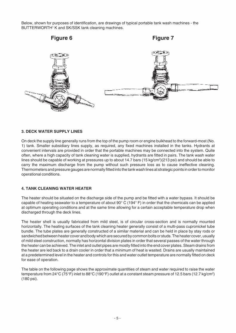
Below, shown for purposes of identification, are drawings of typical portable tank wash machines - theBUTTERWORTH1 K and SK/SSK tank cleaning machines.
Figure 6 Figure 7
3. DECK WATER SUPPLY LINES
On deck the supply line generally runs from the top of the pump room or engine bulkhead to the forward-most (No.1) tank. Smaller subsidiary lines supply, as required, any fixed machines installed in the tanks. Hydrants atconvenient intervals are provided in order that the portable machines may be connected into the system. Quiteoften, where a high capacity of tank cleaning water is supplied, hydrants are fitted in pairs. The tank wash waterlines should be capable of working at pressures up to about 14.7 bars (15 kg/cm2)(213 psi) and should be able tocarry the maximum discharge from the pump without such pressure loss as to cause ineffective cleaning.Thermometers and pressure gauges are normally fitted into the tank wash lines at strategic points in order to monitoroperational conditions.
4. TANK CLEANING WATER HEATER
The heater should be situated on the discharge side of the pump and be fitted with a water bypass. It should becapable of heating seawater to a temperature of about 90° C (194° F) in order that the chemicals can be appliedat optimum operating conditions and at the same time allowing for a certain acceptable temperature drop whendischarged through the deck lines.
The heater shell is usually fabricated from mild steel, is of circular cross-section and is normally mountedhorizontally. The heating surfaces of the tank cleaning heater generally consist of a multi-pass cupronickel tubebundle. The tube plates are generally constructed of a similar material and can be held in place by stay rods orsandwiched between heater cover and body which are secured by common bolts or studs. The heater cover, usuallyof mild steel construction, normally has horizontal division plates in order that several passes of the water throughthe heater can be achieved. The inlet and outlet pipes are mostly fitted into the end cover plates. Steam drains fromthe heater are led back to a drain cooler in order that a minimum of heat is wasted. Drains are usually maintainedat a predetermined level in the heater and controls for this and water outlet temperature are normally fitted on deckfor ease of operation.
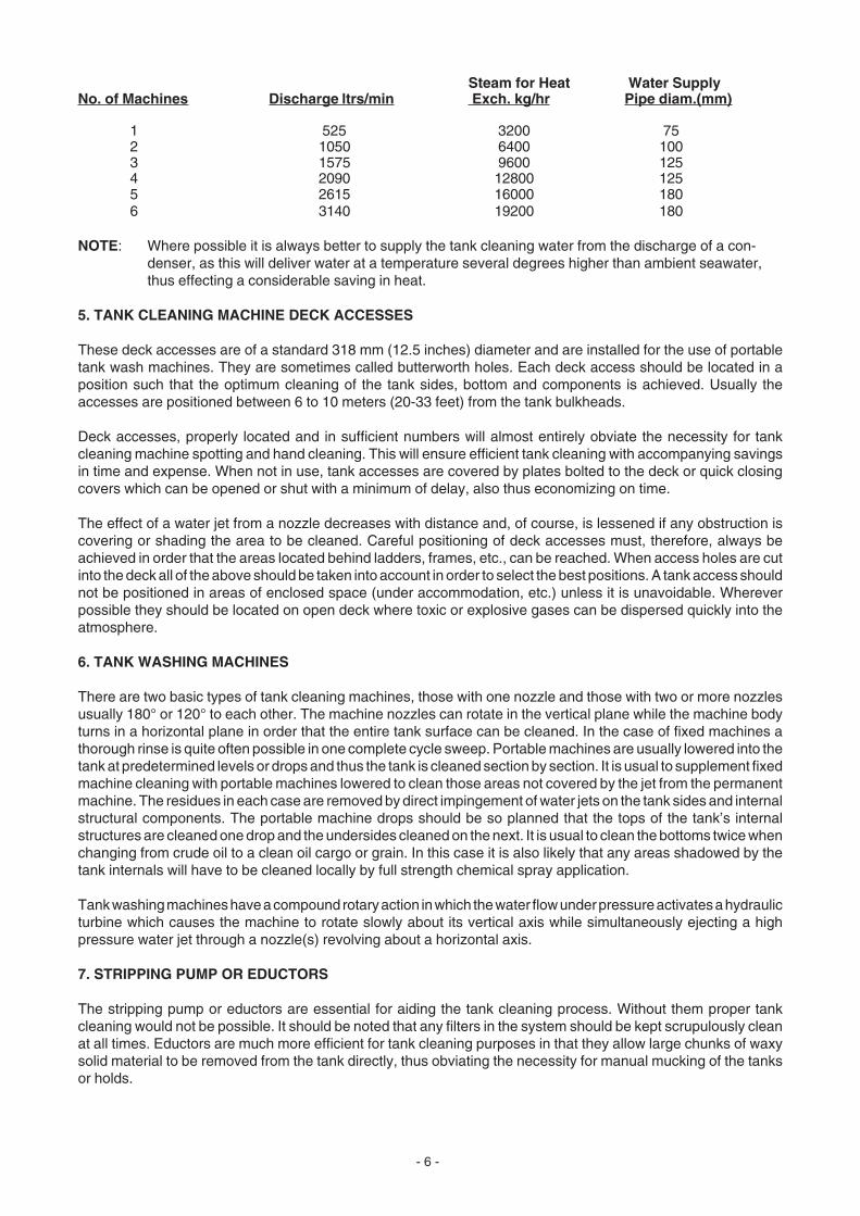
The table on the following page shows the approximate quantities of steam and water required to raise the watertemperature from 24°C (75°F) inlet to 88°C (190°F) outlet at a constant steam pressure of 12.5 bars (12.7 kg/cm2)(180 psi).
- 6 -
Steam for Heat Water SupplyNo. of Machines Discharge ltrs/min Exch. kg/hr Pipe diam.(mm)
1 525 3200 752 1050 6400 1003 1575 9600 1254 2090 12800 1255 2615 16000 1806 3140 19200 180
NOTE: Where possible it is always better to supply the tank cleaning water from the discharge of a con-denser, as this will deliver water at a temperature several degrees higher than ambient seawater,thus effecting a considerable saving in heat.
5. TANK CLEANING MACHINE DECK ACCESSES
These deck accesses are of a standard 318 mm (12.5 inches) diameter and are installed for the use of portabletank wash machines. They are sometimes called butterworth holes. Each deck access should be located in aposition such that the optimum cleaning of the tank sides, bottom and components is achieved. Usually theaccesses are positioned between 6 to 10 meters (20-33 feet) from the tank bulkheads.
Deck accesses, properly located and in sufficient numbers will almost entirely obviate the necessity for tankcleaning machine spotting and hand cleaning. This will ensure efficient tank cleaning with accompanying savingsin time and expense. When not in use, tank accesses are covered by plates bolted to the deck or quick closingcovers which can be opened or shut with a minimum of delay, also thus economizing on time.
The effect of a water jet from a nozzle decreases with distance and, of course, is lessened if any obstruction iscovering or shading the area to be cleaned. Careful positioning of deck accesses must, therefore, always beachieved in order that the areas located behind ladders, frames, etc., can be reached. When access holes are cutinto the deck all of the above should be taken into account in order to select the best positions. A tank access shouldnot be positioned in areas of enclosed space (under accommodation, etc.) unless it is unavoidable. Whereverpossible they should be located on open deck where toxic or explosive gases can be dispersed quickly into theatmosphere.
6. TANK WASHING MACHINES
There are two basic types of tank cleaning machines, those with one nozzle and those with two or more nozzlesusually 180° or 120° to each other. The machine nozzles can rotate in the vertical plane while the machine bodyturns in a horizontal plane in order that the entire tank surface can be cleaned. In the case of fixed machines athorough rinse is quite often possible in one complete cycle sweep. Portable machines are usually lowered into thetank at predetermined levels or drops and thus the tank is cleaned section by section. It is usual to supplement fixedmachine cleaning with portable machines lowered to clean those areas not covered by the jet from the permanentmachine. The residues in each case are removed by direct impingement of water jets on the tank sides and internalstructural components. The portable machine drops should be so planned that the tops of the tank’s internalstructures are cleaned one drop and the undersides cleaned on the next. It is usual to clean the bottoms twice whenchanging from crude oil to a clean oil cargo or grain. In this case it is also likely that any areas shadowed by thetank internals will have to be cleaned locally by full strength chemical spray application.
Tank washing machines have a compound rotary action in which the water flow under pressure activates a hydraulicturbine which causes the machine to rotate slowly about its vertical axis while simultaneously ejecting a highpressure water jet through a nozzle(s) revolving about a horizontal axis.
7. STRIPPING PUMP OR EDUCTORS
The stripping pump or eductors are essential for aiding the tank cleaning process. Without them proper tankcleaning would not be possible. It should be noted that any filters in the system should be kept scrupulously cleanat all times. Eductors are much more efficient for tank cleaning purposes in that they allow large chunks of waxysolid material to be removed from the tank directly, thus obviating the necessity for manual mucking of the tanksor holds.
- 7 -
CHAPTER II
TANK CLEANING CLASSIFICATION AND CERTIFICATIONREQUIREMENTS
1. PRECLEANING TANK SURVEYS
Unless a ship has been employed consistently on a run carrying known cargoes and a routine cleaning method hasbeen satisfactorily established, a survey of the tanks will be necessary in order to determine the tank conditionsand thus the method of cleaning to be adopted. Before commencing any survey, a tank should be proved gas freeand fit to enter. It is therefore almost always necessary to water wash a tank before conducting a survey. A specialnote of any particularly heavy accumulations of tenacious residues should be made and also of any residuesremaining from cargoes other than the last one loaded. Very heavy accumulations of sediment will generally haveto be removed mechanically or by using full strength chemicals to loosen them in order that their removal duringthe cleaning operation will be simplified. The survey should ascertain if rust or scale adheres to the tank surfacesunder the cargo residues for it is in these areas where contaminants accumulate which will pollute the followingcargo. If a survey proves to be inconclusive, then samples of the residues and/or scale should be taken andanalyzed to determine the cleaner to be used.
Tank cleaning and its related activities, such as slop disposal, entering of tanks, etc., are governed by certaininternational, national or local laws and port or company regulations and should be adhered to.
The holds or tanks of any ship must be cleaned after discharge in order that conditions of cleanliness required bythe charterer or shipowner and consignee or receiver, are met in respect to carriage of the next cargo and itssubsequent delivery in an uncontaminated state. The above applies particularly to edible cargoes and certaingrades of chemicals and petroleum distillates which must be delivered not only in an uncontaminated condition withrespect to discoloration, but also without traces of foreign odors.
Various certificates are issued to ships by independent or official classification societies and inspectors. Certaincertificates are required for the vessel to trade internationally, others are issued to govern the entry into tanks bypersonnel and yet others to permit the loading of a cargo.
2. CERTIFICATE CLASSIFICATION
a. Certificate of Class: In order that a Certificate of Class be issued and thereafter renewed, every part ofa ship must be surveyed within a specific period of time. This regulation applies equally to the holds and tanksof any ship as well as to other parts of its structure. In order that tanks and holds can be surveyed properly,they must be cleaned out to a degree where sediments and residues do not encumber the inspection.Furthermore, the tanks must be gas free in order that the surveyor may enter the tank without hazard.
b. Gas-Free Certificate: This certificate is issued by a licensed marine chemist whenever personnel arerequired to enter a tank for purposes of performing small repairs not requiring hot work, or for cleaning orinspection. The certificate is issued after the toxic and/or explosive gases have been removed from the tankby means of mechanical ventilation and/or tank cleaning with cold or hot sea water with or without theaddition of a chemical.
If a tank is to be gas free in order to perform hot work or shipyard repairs, then a more stringent cleaningis necessary. The Gas Free Certificate for hot work confirms that the tank is not only free from explosiveand/or toxic gases, but it is also free of scale adhering to the top, sides or bottom of a tank. These may concealpockets of oily or petrochemical matter which, under certain conditions, may give off combustible gases.It also confirms that all loose scale, oil, sludge and residues have been removed from the tank bottom andthus the danger of regenerated vapor or gases which may ignite on application of heat have been removed.The vessel carries its own gas monitoring meters in order that the operating staff can verify if a tank is fitfor men to enter after gas freeing is accomplished.
- 8 -
c. Coating Compatibility Certificate: It is often necessary to obtain a certificate in order that certainchemicals or products can be carried in a tank that has been painted with an inorganic or organic coating.Coating resistance to various chemicals is an important factor when deciding which cargo can be loaded.Also, governmental authorities do maintain regulations governing the carriage of any dangerous materialin tanks that may not be either properly prepared or “inerted.”
d. Certificate of Complete Cargo Discharge: A certificate of discharge must be obtained at many ports whencarrying certain dangerous cargoes to confirm that the shipment has been removed from the tank ascompletely as possible so that cleaning can therefore commence without likelihood of residues of a toxiccargo being pumped.
e. Local Government Health Certificate: When a cargo requiring special conditions of cleanliness for itscarriage has to be loaded into a tank, it is usual to obtain a certificate indicating the condition of the tank withrespect to its freedom from contaminants and odor. This certificate is usually issued by a Governmental orlocal health inspector.
f. Independent Surveyor Certificate: In the case where a vessel has to load a cargo which may or may notbe compatible with a previous cargo, an independent survey of the tanks may be required to be done by alocal expert. After a tank inspection he will give advice on the type and extent of cleaning required in orderthat the incoming cargo can be loaded and delivered to the receivers in an uncontaminated condition. In thiscase it is likely that the consignee will require a copy of the above certificate before he will accept deliveryof the cargo.
- 9 -
CHAPTER III
TYPES OF LIQUID CARGOES
To clean the remains of a cargo from a tank or hold and to present it in a condition fit for loading a different cargogenerally involves a considerable quantity of work.
The method adopted for cleaning any liquid cargo residues from a tank depends chiefly upon the type of cargoinvolved and its physical and chemical properties.
Some chemical cargoes are extremely toxic and thus dangerous to personnel when exposed to the fumes. Othercargoes are quick drying and their residues tenacious which can cause a cleaning problem unless approached inthe correct manner. Other cargoes can be water soluble or highly volatile and require almost no special cleaningprocess to totally remove their presence from a tank. Physical removal of some products may be easy but they mayleave a strong odor which must be displaced before the next cargo is loaded. To do this another special processmust be employed.
From the above it can readily be seen that several different processes are required to remove the large variety ofproducts carried by vessels today. For the purpose of tank cleaning, cargoes can be subdivided into threecategories:
• Mineral oils• Animal, fish and vegetable oils and fats• Solvents and chemicals
The three categories above can be further subdivided into various groupings according to their origin, physicalcharacteristics and chemical behavior, especially under varying atmospheric and thermal conditions.
1. MINERAL OILS
These oils may be divided into four groups based on their degree of distillation or refining:
• Petroleum-based heavy products• Coal-based heavy products• Distillates of petroleum• Distillates of coal
2. ANIMAL, FISH AND VEGETABLE OILS AND FATS
These products can be divided into four groups according to their properties and behavior when exposed toatmospheric conditions and the effect that oxygen has upon each of the products. Fats are natural organic productswith a freezing point at or below 20°C (68°F). In other respects they are similar to natural oils. The four groups are:
• Non-drying oils• Semi-drying oils• Drying oils• Water soluble products
It must be noted that some vegetable oils have the property of absorbing or reacting with oxygen from the air aroundthem. Vegetable oil residues remaining in a tank after pumping out can be affected in this way. Continuousventilation preferable by means of mechanically operated power driven fans with a discharge to the tank bottomsshould always be employed. This is especially true when a tank in which the residues of an oxygen scavenging oilremain and has to be inspected or the deposits removed from the tank bulkheads and frames.
Water soluble products, such as molasses, can be removed from the tank surfaces merely by washing withcold water.
- 10 -
3. SOLVENTS AND CHEMICALS
Today, chemicals and solvents include a vast and complex range of commodities. There are already severalhundred which can be carried at sea in liquid form. Many of these are entirely harmless, while others can beextremely dangerous if mishandled. Some chemicals contain enough oxygen to enable them to burn withoutadditional supplies from the air.
Certain chemicals are hazardous and very dangerous to handle. Some chemicals must never be inhaled, evenin the smallest quantities. Others can be absorbed through the skin into the blood stream, and reach vital organs.Obviously, these should never be allowed to come into direct contact with the skin.
Finally, some chemicals are extremely corrosive. Hydrochloric acid is an obvious example, but there are others.Corrosive chemicals can cause severe burns if they contact the skin or cause blindness if they enter the eyes.Strong alkalies can have similar effects as those described for acids.
Protective clothing and goggles are essential when working with corrosive chemicals. A complete chemicalresistant suit with helmet and respiratory equipment can be required when handling certain obnoxious products.Remember to follow the instructions and all precautionary warnings when dealing with or handling strong acids oralkalies.
Chemicals and solvents can be divided into two broad categories for the purpose of tank cleaning:
• Volatile liquids with high vapor pressure and low boiling point
• Low volatile liquids with low vapor pressure and low boiling point above 100°C (212°F)
- 11 -
CHAPTER IV
TANK CLEANING CHEMICALS
The action of chemicals used in tank cleaning can be divided into several different categories.
1. SOLVENTS
Solvents are chemicals which dissolve or solubilize other materials or chemicals. In this way residues and depositsare removed from the tank surfaces, permitting them to be pumped to slop tanks for disposal.
2. SURFACE ACTIVE AGENTS (Surfactants)
Surface active agents are usually detergents which act to reduce the surface tension of a liquid and thus to improveits wetting and cleaning capabilities. They are usually used together with solvents to produce a cleaning solutionwhich aids in the complete removal of tank residues, such as hydrocarbons, liquid chemicals, etc.
3. EMULSIFIERS
An emulsifier is a surface active chemical which forms an emulsion of two liquids. One liquid is present as extremelysmall droplets, such that particles or globules of it are dispersed and suspended in the other, i.e., oil-in-water. Thissuspension often gives a milky appearance.
Emulsification is assisted and sustained by chemicals which consist of molecules with one end hydrophilic (waterseeking) and the other end lipophilic (oil seeking). Utilizing this property, an emulsifier makes it possible to removeoily deposits with water. Many products acquiesce to this action, and several different types of emulsifiers are usedfor removal of a variety of materials. Emulsification does not usually involve chemical change of either solution butmerely suspends particles of one product within the other, which in turn gives rise to the milky appearance of thesolution.
4. SAPONIFIERS
A saponifier is an alkaline chemical which changes oils and fats into soaps by converting the fatty compounds intowater soluble materials which are biodegradable and easily flushed away from the surfaces to which they adhere.
Strong alkali solutions (NaOH and KOH) are used as saponifying agents together with a variety of other compoundsin order to deal effectively with the large variety of animal, fish and vegetable oils being transported around the worldtoday. One minor problem with the above process is to estimate the exact quantity of saponifier required toneutralize these types of residues. Normally, the neutralized residues of this process are readily biodegradable.However, if an excessive quantity of alkali is used, not all of it will be chemically converted in the cleaning process.The excess remaining can be harmful to the environment.
5. DREW MARINE TANK CLEANING PRODUCTS
The product usually recommended by Drew Marine for removing mineral oil deposits include:
• TC#4TM tank cleaner
A liquid oil solvent emulsifying detergent with hydrophilic properties used for the removal of petroleumproduct residues from tanks. TC#4 tank cleaner is used for cleaning crude oils and fuel oils.

- 12 -
• DREW™ TC SEA tank cleaner
A strong emulsifying cleaner for removing heavy petroleum-based stains such as heavy crude oil, soot,asphalt and carbon black. Equally effective for cargo and storage tank washing and recirculation, directinjection and manual spray methods. It also works well with agitation from the ship's rolling motion to cleanand gas-free double bottom tanks.
• O&GR™ oil and grease remover
A neutral blend of active cleaning agents and emulsifying solvents. It penetrates and dissolves grease, oiland grimy soils forming a soluble mixture which can be rinsed away with water. It can be used as a cleanerfor metal, parts and tools, painted and unpainted surfaces, decks, bulkheads, machinery, engines andwherever grease, oil and grimy soils are a problem.
• ENVIROCARE® 370 heavy-duty solvent cleaner
A solvent-based coal tar solubilizer and emulsion cleaner for the removal of coal tar, crude benzene, bitumenand similar substances. It can be used for cleaning heavily contaminated metal parts as well as for tankcleaning. Upon sitting, a solution of water and ENVIROCARE 370 cleaner will separate, leaving water at thetop while the cleaner and contaminants sink to the bottom.
• ENVIROCARE 480 heavy-duty cleaner
An non-flammable, high-performing microemulsion cleaner with biodegradable components designedespecially for removing difficult baked-on oils, carbonized deposits, paraffin waxes and heavy greases. It canbe used neat or diluted with fresh or sea water.
• HDE-777TM heavy duty emulsifier
A solvent solution of low foaming detergents and emulsifiers for cleaning petroleum product residues fromcargo and oil tanks or holds. It is also suitable for cleaning oil product residues from the sides of cargo carryingtanks.
• OSD/LTTM oil spill dispersant
A low toxicity blend of wetting agents and dispersants in a fast penetrating oil soluble liquid vehicle,specifically designed to disperse oil spills. It can also be used to remove oil residues from tanks and holds.OSD/LT dispersant is approved by 12 government bodies worldwide.
• AMEROID® OWS quick separating degreaser
AMEROID OWS quick separating degreaser is a superior solvent emulsifying product for general engineroom degreasing and for cleaning and gas-freeing of bilges. Its unique blend of surfactants, wetting agentsand solvents results in a product which has exceptional cleaning properties, breaks quickly, and does notharm the operation of the oily water separators required under the Marpol regulations.
The products usually recommended by Drew Marine for removing the residues of animal, fish or vegetable oils areEDGE® heavy duty cleaner and LAC™ liquid alkaline cleaner.
• EDGE heavy duty cleaner
This cleaner has been formulated specifically to meet the tank cleaning requirements of the marine industrywith special attention to safety and environmental considerations. EDGE cleaner combines heavy dutycleaning chemicals with fast penetrating and wetting agents for the power required to remove stubborn soilswhile remaining sufficiently mild to cause no harm to almost all tank cleaning surfaces. EDGE cleanerprovides an excellent alternative to traditional solvent-based and highly alkaline cleaners and can be usedin a multitude of varying cleaning applications. EDGE cleaner is suitable for use in zinc silicate-coated tankswhen diluted, preferably with fresh water.
• LAC liquid alkaline cleaner
This product is a heavy duty liquid alkaline cleaner that can successfully clean non-drying, semi-drying anddrying oils from cargo tanks or holds. It has excellent deodorizing properties and can also be used in a dilutesolution as a final flush in preparation for the next cargo.
- 13 -
Other products available
• MUD CONDITIONER™ ballast tank water treatment
A high weight polymer containing product specifically designed to condition mud and silt bearing water. MUDCONDITIONER reacts with the mud and silt to form large non-adhering particles which quickly settle to thebottom of the tank. The result is loosely dispersed particles that can be easily discharged with the ballastwater.
• ENVIROMATE® 2000 general purpose cleaner
A water-based cleaner formulated to meet the marine industry's strict requirements for safety andperformance. With its unique blend of cleaning agents, it is a non-flammable, biodegradable general purposecleaner perfect for a broad range of deck, offshore, hotel and galley applications.
• DREW™ BC buffering cleaner
Removes traces of metal oxide stains from zinc-silicate coated tank surfaces. It is used as a final cleaningprocedure when cargo residues must be removed or when the tank has to be completely chloride or sulfidefree when shipping pure chemicals.
• DREW ABD alkaline-based degreaser
A very strong alkaline liquid cleaner applied by injection or recirculation methods, that economically removesanimal, fish, and vegetable oils and fats. Suitable for use on most common metals and tank coatings.
• DREW NBD neutral-based degreaser
A neutral liquid degreaser safe for use on most metals including zinc silicate-coated tanks. An effectivecleaner for animal, fish and vegetable oils and fats, this product is injected or circulated through mechanicalsystems and can be used undiluted for manual spraying. It can also be applied as a final treatment followinghydrocarbon-free cleanings with emulsifying cleaning agents.
• AMEROID® RSR rust stain remover
A liquid combination of rust dissolving acid, emulsifier and passivator for removing rust. Used for eliminatingsalt residue, it is injected into the automatic washing system.
• DREW AF air freshener
A water-based liquid used to eliminate unpleasant odors in tanks and domestic areas. It is safe to use onmost common metals and coatings.
Only cleaners listed on the IMO MEPC.2/CIRC.6 can be used and disposed of at sea for cargo tank cleaning whenthe cargo residue slops are disposable at sea.
- 14 -
CHAPTER V
TANK COATINGS
Large tankers and OBO vessels are usually constructed of mild steel. Parts of the tanks or holds are often coatedwith inert coatings to protect them from the more aggressive cargoes. It is common to find product carriers havingtheir tanks and internals coated to render their surfaces inert and protect them from active chemical cargoes. Shipswhich carry the most highly aggressive cargoes have their tanks constructed from, or covered with, stainless steelsheathing in order that they are rendered passive and will not corrode excessively under the action of the moreactive chemicals.
1. THE PURPOSE OF TANK COATINGS
The internal lining of a ship’s cargo and ballast tanks is a common practice undertaken in order to prevent corrosion,cargo contamination and to facilitate cleaning and sludge freeing.
In crude/refined oil tankers, coatings are intended to prevent corrosion, and reduced scantlings may be permittedwhen approved coatings are applied The main purpose of tank coatings in bulk chemical carriers is usually toprevent cargo contamination. Many chemicals are sensitive to contamination by iron, either from rust or from thesteel of the tanks. Due to the fact that the standards regarding contamination of chemical cargoes are far stricterthan those for oil and its products, it is essential to place a chemically inert barrier between the cargo and the tanksurface when carrying active chemicals. Oil products do not consist of a single component, but rather are a blendof components giving the required properties. Therefore, a slight mixing of cargoes of different grades may betolerated within defined parameters.
Chemical cargoes, however, are of a more specific nature and will not tolerate any contamination. In this context,the efficient cleaning of tanks is of considerable importance. An unlined tank will retain traces of cargo to a muchgreater extent than the smooth surface of a coated tank. Cargo is removed only with difficulty from pitted surfaces,and in addition to contamination, can also give rise to the risk of explosion and toxicity if cleaning and gas freeingare imperfectly executed.
2. THE ESSENTIAL COMPONENTS OF PROTECTIVE TANK COATINGS
Any coating - primer coat, body coat or finish - has four essential components:
• Pigment - The pigment contributes color (a coating’s hiding power), and extender pigments are used tomodify viscosity, film strength, hardness, abrasion resistance, protection from ultraviolet rays and rustinhibitive properties.
• Solvent - The solvent dissolves the resinous vehicle and turns it into a usable form. Solvents control theviscosity and the way the coatings brush or spray on, settle, level and dry. Typical solvents include mineralspirits, glycol, ethers and xylene.
• Additives - The additives impart properties which are not contained in the other three components. Additivesserve as agents for drying, wetting, film build, and pigment suspension.
• Vehicle - The vehicle is the most important coating component. It is the binder or “film former” that bindspigments together and anchors the coating to the surface. The type of vehicle in a coating determines filmthickness, adhesion, consistency, hardness, flexibility, durability, gloss and color retention, drying time andthe coating’s ability to resist corrosive agents such as water, chemicals and solvents.
The vehicles are usually resinous substances. They are cured or transformed in the coating from a liquidor plastic state to a hard, protective film by one or more the following methods:
- 15 -
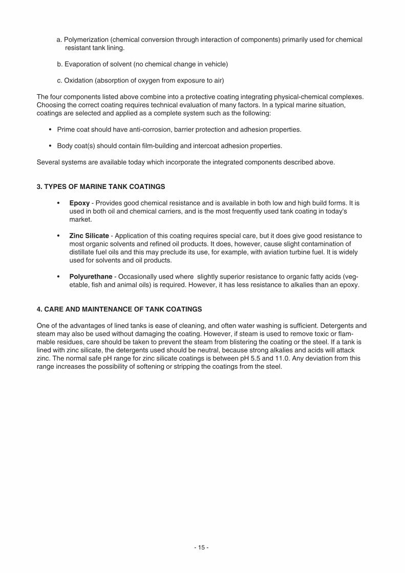
a. Polymerization (chemical conversion through interaction of components) primarily used for chemicalresistant tank lining.
b. Evaporation of solvent (no chemical change in vehicle)
c. Oxidation (absorption of oxygen from exposure to air)
The four components listed above combine into a protective coating integrating physical-chemical complexes.Choosing the correct coating requires technical evaluation of many factors. In a typical marine situation,coatings are selected and applied as a complete system such as the following:
• Prime coat should have anti-corrosion, barrier protection and adhesion properties.
• Body coat(s) should contain film-building and intercoat adhesion properties.
Several systems are available today which incorporate the integrated components described above.
3. TYPES OF MARINE TANK COATINGS
• Epoxy - Provides good chemical resistance and is available in both low and high build forms. It isused in both oil and chemical carriers, and is the most frequently used tank coating in today'smarket.
• Zinc Silicate - Application of this coating requires special care, but it does give good resistance tomost organic solvents and refined oil products. It does, however, cause slight contamination ofdistillate fuel oils and this may preclude its use, for example, with aviation turbine fuel. It is widelyused for solvents and oil products.
• Polyurethane - Occasionally used where slightly superior resistance to organic fatty acids (veg-etable, fish and animal oils) is required. However, it has less resistance to alkalies than an epoxy.
4. CARE AND MAINTENANCE OF TANK COATINGS
One of the advantages of lined tanks is ease of cleaning, and often water washing is sufficient. Detergents andsteam may also be used without damaging the coating. However, if steam is used to remove toxic or flam-mable residues, care should be taken to prevent the steam from blistering the coating or the steel. If a tank islined with zinc silicate, the detergents used should be neutral, because strong alkalies and acids will attackzinc. The normal safe pH range for zinc silicate coatings is between pH 5.5 and 11.0. Any deviation from thisrange increases the possibility of softening or stripping the coatings from the steel.
- 16 -
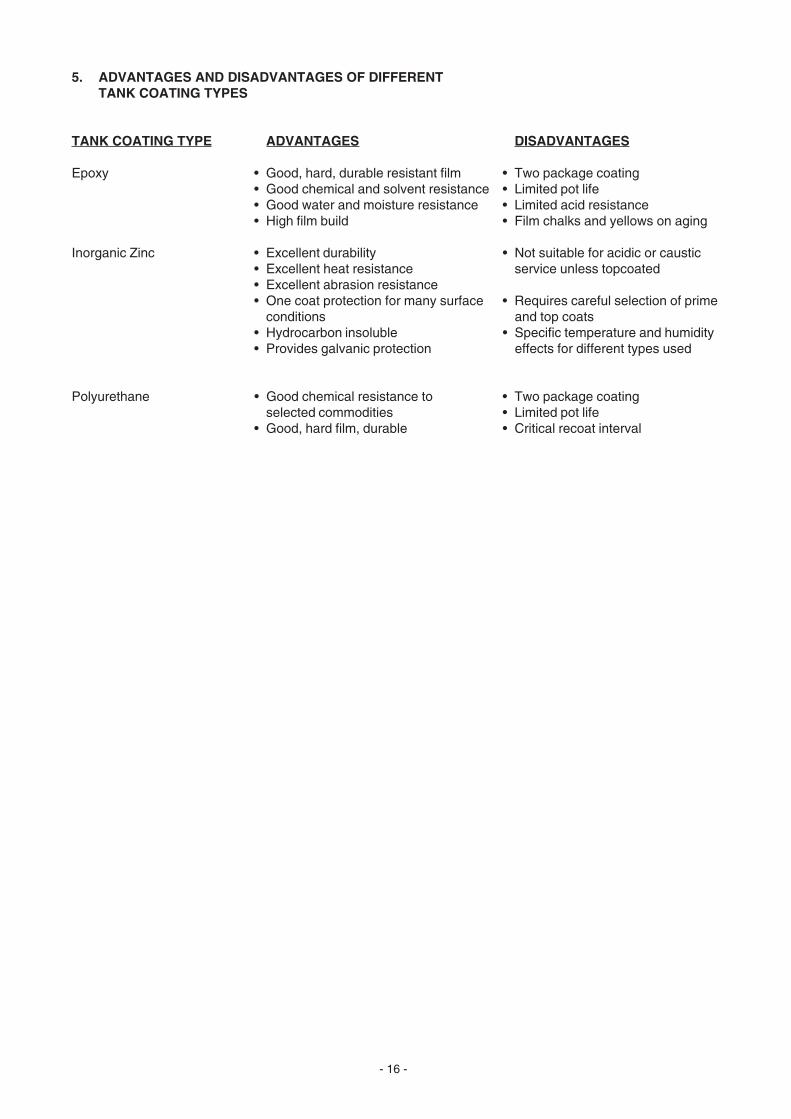
5. ADVANTAGES AND DISADVANTAGES OF DIFFERENTTANK COATING TYPES
TANK COATING TYPE ADVANTAGES DISADVANTAGES
Epoxy • Good, hard, durable resistant film • Two package coating• Good chemical and solvent resistance • Limited pot life• Good water and moisture resistance • Limited acid resistance• High film build • Film chalks and yellows on aging
Inorganic Zinc • Excellent durability • Not suitable for acidic or caustic• Excellent heat resistance service unless topcoated• Excellent abrasion resistance• One coat protection for many surface • Requires careful selection of prime
conditions and top coats• Hydrocarbon insoluble • Specific temperature and humidity• Provides galvanic protection effects for different types used
Polyurethane • Good chemical resistance to • Two package coatingselected commodities • Limited pot life
• Good, hard film, durable • Critical recoat interval

- 17 -
6. COMPATIBILITY OF DREW MARINE PRODUCTS WITH VARIOUS MATERIALSENCOUNTERED IN TANK CLEANING APPLICATIONS
The chart below shows the compatibility of several of Drew Marine recommended cleaning products in solution withvarious materials (generic forms). It can be used as a guide to indicate whether compatibility exists between thecleaner and such items as heating coils, wash hoses and other similar components.
Materials or coatingsYes = Compatible; No = Not Compatible; * = See Footnote
Drew Marine Ferrous Nonferrous Rubber Plastic Oil Inorg. Chlorinated Products Metals Metals Products Products Based Latex Epoxy Zinc Rubber
TC#4TM tank cleaner Yes Yes * * * * Yes Yes No
HDE-777TM Yes Yes * * * * Yes Yes No heavy duty emulsifier
OSD/LTTM Yes Yes * * * * Yes Yes No oil spill dispersant
LACTM Yes No Yes Yes Yes Yes Yes No Yes liquid alkaline cleaner
EDGE® Yes * Yes Yes Yes Yes Yes * Yes heavy duty cleaner
AMEROID® OWSquick separatingdegreaser Yes Yes * * * Yes Yes Yes No
AMEROID RSRrust stain remover * No Yes Yes Yes Yes Yes No Yes
DREWTM ABDalkaline-baseddegreaser Yes No Yes Yes Yes Yes Yes No Yes
DREW BCbuffering cleaner * * Yes Yes Yes Yes Yes Yes Yes
DREW NBDneutral-baseddegreaser Yes Yes Yes Yes Yes Yes Yes Yes Yes
DREW TC SEAtank cleaner Yes Yes * * * * Yes Yes No
ENVIROMATE® 2000general purpose Yes Yes Yes Yes Yes Yes Yes Yes Yescleaner
ENVIROCARE 370 Yes Yes No * No Yes Yes Yes Noheavy duty solvent cleaner
ENVIROCARE 480 Yes No Ys Yes Yes Yes Yes * Yesheavy duty cleaner
DREW AFair freshener Yes Yes Yes Yes Yes Yes Yes Yes Yes
O&GRTM
oil and grease remover Yes Yes * * * * Yes Yes No

- 18 -
7. PROBLEMS ARISING WITH TANK COATINGS AND THE CARRIAGE OF CERTAIN CARGOES
The copper strip test for corrosive metals is conducted by exposing a copper strip to the liquid to be tested for apredetermined period, at either 50° C or 100° C (122° F or 212° F). It is then compared to standard test strips andgraded from light orange to jet black on a scale ranging from No. 1 to No. 4.
Occasionally, after the carriage of certain cargoes that have a high sulfur compound impurity content (e.g., virginnaphtha), it is likely to find that the copper corrosion test is out of specification.
This negative result of the copper corrosion test can be attributed to the formation of corrosion products such aszinc and iron sulfides on the tank surfaces, especially in the micropores of the zinc silicate coating.
These sulfides require special treatment for removal, because zinc silicate coatings are sensitive to high pH rangeeffects. The generally accepted method of cleaning is by using an acid cleaner limiting its concentration to a pH of5.5 for zinc silicates. This particular concentration is important as the resistance to acid attack decreases rapidlyat pH 4.9 and serious damage will therefore result to the coating.
Epoxy coatings are much less sensitive to the effects of wide range pH values and can be safely cleaned using anacid limiting its concentration to a pH of 4.5.
8. STAINLESS STEEL TANKS
Stainless steel is an alloy of iron containing a relatively high proportion of chromium (12-20%) and other metals suchas nickel, vanadium and cadmium. The chromium in the alloy reacts with the oxygen of the atmosphere to createan inert oxide coating which will protect the metal from corrosion or attack by aggressive chemicals.
Before the protective chromium oxide layer can be created, it must be treated with a dilute solution of nitric acid(usual concentration about 10%). This solution is allowed to remain in contact with the surface for about two hours,after which it is flushed away with distilled water. Seawater should not be used for this task as it can generate chlorineand precipitate chemical salts in the process which activate the stainless steel so that it becomes active andtherefore nonresistant to corrosion.
In order that the entire tank is rendered passive, the chromium oxide layer must completely cover the tank surface.With the entire tank surface in the passive condition, it will be protected from the attack of most aggressive cargoes.If the tank surface coating becomes damaged by mechanical abrasion, by welding or as a result of a chemical attackwith such products as oleic acids, it will become active and require re-passivating by an oxidizing agent which greatlyspeeds up the natural oxide-producing process which occurs if the tank is untreated.
When using dilute nitric acid to passivate a stainless steel tanks, all safety recommendations should be observed.These involve the wearing of special protective clothing, face masks, rubber boots and breathing apparatus, whereappropriate. To passivate new tanks or re-passivate damaged tanks, the surfaces must be sprayed or brushed witha 10% nitric acid solution (0.1N concentration) and allowed to soak the proper time interval before being flushedaway using chloride-free water.
To determine if a tank fabricated of stainless steel is active or passive, a test using palladium reagent must be used.If the area tested is active, it will turn the palladium solution black. If the area is passive, the palladium reagent willbe unaffected.
Tanks which have suffered damage in some way and have become partially active will return to a passive statenaturally. However, this process will normally take far too long for commercial purposes and it must be aided bythe application of an oxidizing agent in the manner described above.
*The products in this category can be considered as “mildly incompatible” when in contact with the materials orcoatings indicated. The degree of attack which possibly may occur will depend upon the specific constituents, ageand condition of the surface to be cleaned, the cleaner solution strength, its temperature, and contact time. Asolution strength of 10% or less at the recommended temperature should ensure no deleterious effects on the tankssurfaces or coatings.
- 19 -
CHAPTER VI
THE TANK CLEANING PROCEDURE
The procedure for tank cleaning can include all or a combination of some of the following stages:
• Precleaning (Tank washing with seawater)• Cleaning (Tank washing with seawater and cleaning chemicals)• Steaming (Introduction of steam and sometimes extra tank cleaning chemicals)• Rinsing (Tank washing with seawater)• Flushing (Tank washing with fresh water)• Draining (Removing the last traces of liquids)• Drying (Ventilating, deodorizing and drying)
1. PRECLEANING
Before commencing the precleaning operation, a careful study should be made of the internal tank structurefrom the ship’s construction drawings. The depth of the portable tank wash machine drops must beestablished by noting the height of the intercostal transverse frames, bulkhead web frames, horizontal strutsand any other internal encumbrances which may interfere with efficient cleaning. The portable tank washmachine should always be lowered to a position where it is approximately midway between beams so thatthe water will impinge progressively on both the top side and under side of the internal structures thus ensuringmaximum cleaning area exposure.
Precleaning tanks (or holds) with fixed or portable tank cleaning machines, using sea or fresh water as thecleaning medium, is done to remove oil and other waxy residues from the frames, bulkheads, tank tops, tankbottoms and any pipework or other components within the tank. The remaining oil and/or chemical residueswill be removed far more easily if cleaning is initiated immediately after the tank has been emptied and beforethese residues have been allowed to oxidize or polymerize and solidify.
The importance of precleaning cannot be overstressed. It is during this process that the heavy and by far thelargest percentage of the deposits remaining are removed in order to ensure an effective cleaning operation(see “Cleaning” below). For precleaning drying oils, cold water (sea or fresh) should be used. For precleaningoils with a high pour point, use water a few degrees higher than the pour point. Oxidation and polymerizationwill cause drying oils to harden under the influence of heat and the resultant product will adhere to the tankbulkheads and be very difficult to remove.
Generally, tanks which have carried crude oils should be cleaned first with cold water for about two hours andthen with warm water if required. Precleaning should be continued until the tanks are sufficiently clean toproceed with the main cleaning process. No precise time can be given as it depends entirely upon the typeand grade of cargo to be removed and the size and condition of the tanks from which it is being removed. Largeand small tanks generally take a similar time to clean due to the fact that small tanks tend to contain moreobstacles, such as frames, girders, stringers, etc., which will encumber the cleaning operation. During theprecleaning period the portable tank cleaning machines should be moved frequently around the tanks(horizontally and vertically) in order that all surfaces are reached. When precleaning has been completed, andwhen the tanks are deemed safe to enter, an inspection should be made to ascertain the condition and thedegree of cleaning required to render the tanks acceptable for the next cargo. Particular attention should begiven to the tank bottoms and any hidden areas.
2. CLEANING
For this process a dilute solution of a chemical is required. The solution is normally heated to a minimumtemperature of 40° C (104° F) up to a maximum of 90° C (194° F) (higher temperatures are more effective)and stored (if the recirculation method is to be used) in either a special chemical tank, slop tank, orcofferdam,whichever is convenient and has a suction line to the tank cleaning pump and a return line fromthe tank(s) being cleaned. Correct preparation before commencing the chemical cleaning is essential for itis usually impossible to enter tanks once the operation has started. The chemical solution is applied by wayof the tank cleaning machines, portable and fixed (if available).

- 20 -
The portable machines must be lowered and raised at regular intervals to achieve effective cleaningthroughout the tank. Chemical cleaning is usually continued for one to four hours. The cleaning time involveddepends to a great extent upon the cargo being removed and the cargo to be received, as well as thetemperature of the cleaning solution. After the tank has cooled and it has been passed as fit to enter, it shouldbe inspected. If traces of cargo remain, cleaning should be continued. Inspection of hidden spots is particularlyimportant. Any shaded areas which have not been cleaned must be spot cleaned by hand using “neat” (full-strength) chemical and then flushed away by hand-held hoses.
3. STEAMING
If it is required to steam out a tank to free it of any last remnants of deposits, one of our solvent-type tankcleaning chemicals, toluene or chloride-free water should be sprayed on the tank surfaces and then steamhoses should be inserted into the tank or hold. All hatches and tank lids should be shut, but left loose in orderthat a high pressure does not build up. Tank vents should be held open. Steam is injected into the tank viaopen end hoses. The steam will condense on the sides, top and bottom of the tank and release the lastremaining traces of the contaminant. Check to see that all steam line flanges are properly gasketed and tightlysecured.
To remove all of the cargo residues from the pores of a tank coating, steaming should be carried out togetherwith a cleaning chemical that is compatible with the tank coating.
4. RINSING
Immediately after the cleaning operation is concluded and the tanks have been completely stripped of theresidues and slops, they should be rinsed using the tank cleaning machines and hot or cold seawater. Rinsinggenerally takes between one-half and two hours and is continued until no trace of cleaning detergent can befound.
5. FLUSHING
Flushing is effected using fresh water from the storage tanks. The water is sprayed on deckheads, bulkheads,tank tops, stringers, etc., through hoses fitted with special nozzles.
6. DRAINING
Tanks, lines and pumps should be drained completely. Plugs should be removed and the lines blown throughwith compressed air. An ejector can be used to remove any quantities of water remaining on the bottom ofthe tank.
7. DRYING
The tanks must be throughly ventilated and dried out, then inspected for any residues. Any remainingcontaminants should be removed by wiping down with rags. Valves should be drained into a bucket. It is agood idea for those entering the tank, at this stage, to put shoe covers on or wrap clean lint-free rags aroundtheir shoes. The tank is now completely dried using air fans. As a safety precaution, the tank should be enteredonly if it is confirmed as safe for entry.
Valves and plugs are to remain open until the inspection by the surveyor is completed. Thoroughly ventilatingthe tanks will also aid in the deodorizing process.
Various combinations of the above processes are required to clean and remove the residues of differentcargoes. A cross-reference table is given at the end of this manual detailing some of the combinations mostcommonly encountered today.

- 21 -
8. THE REASONS FOR TANK SURVEY FAILURES
• Wet tank bottom, sides or top (condensation)
• Scale adhering to the tank surfaces
• Bleeding of oil from behind scale or from cracked tank welds
• Dried or hard residue under beams, heating coils, frames, etc.
• Odor (This can be removed by rinsing with a dilute solution of DREW™ AF air freshener, EDGE® heavyduty cleaner or LAC™ liquid alkaline cleaner.)
• Sediment remaining on the bottom, especially beneath lightening holes
- 22 -
CHAPTER VII
METHODS OF USING CHEMICALS FOR CLEANING PURPOSES
The four methods of cleaning by chemical are listed below:
• Recirculation• Hand spraying and atomization• Rock and roll• Direct injection and hot water cleaning
1. RECIRCULATION METHOD
A dilute chemical solution is prepared in a slop tank, cofferdam, cargo tank or specially provided tanks,circulated via the washing system line to the tank to be cleaned and then stripped back to the chemical holdingtank (usually by a second pump). Personnel involved must wear protective clothing, shoes, goggles andgloves. The facilities available on board will determine which tank is used for holding the chemical solution.The best method of heating the chemical solution is to pass it through the tank cleaning heater. However, thisis not always possible unless temporary connections are made. Other ways of heating the solution are by thetank heating coils (care must be taken if using LAC™ liquid alkaline cleaner to ensure that the heating coilmaterial is compatible) or by the steam injection method, both of which can be slow and costly in terms of fueloil used. Each batch of chemical cleaner should be renewed after cleaning three or four tanks (depending onsolution condition). Adding neat chemical to a spent solution should not be practiced as it is both wasteful andinefficient. Each solution batch should be made fresh and heated (if possible) by the most efficient means.
2. HAND SPRAY AND ATOMIZATION METHOD
Undiluted liquid chemical is sprayed directly onto the tank surfaces and internal components using airoperated drum pumps and hand spray guns. After a sufficient soaking period (during which the chemicalreacts with the residues) the tanks are washed with fresh or sea water utilizing the tank washing machinesor hand-held high pressure, large volume water hoses.
The hand spray method is generally the most economical in respect to chemical consumption, but it requiresthat the tanks are gas free to enable personnel to enter for spraying. This is a disadvantage in that the totaltime is considerably increased, and as the physical size of the tanks becomes greater, it becomes increasinglyimpractical. Vessels up to a size of about 30,000 dwt can be cleaned by this method if good equipment andcrew are available. Above this size, mechanical cleaning systems become essential.
For personnel to enter a tank to accomplish this task, all safety instructions must be followed. They must wearprotective clothing, shoes, goggles, gloves and respirators when required. Any chemicals inadvertentlycoming in contact with the body should be washed off using copious quantities of fresh water. Refer to theMaterial Safety Data Sheets for details.
When a very high standard of cleaning is required, (i.e., when upgrading—changing from crude oil to jet fuelor grain), hand spraying is usually necessary after the normal mechanical cleaning has been completed. Thiswill remove the remaining residues that the tank cleaning machines could not remove. The tank is thenwashed down using hand-held hoses. TC#4™ tank cleaner is suitable for spot cleaning as described above.
Atomization is similar to hand-spraying except that the undiluted chemical is applied at high pressure througha lance lowered into the tank. After all surfaces have been covered and thoroughly saturated by a spray ofcontrolled particle size, the tank is washed by hot sea or fresh water. Using the atomization method, it is notnecessary to gas free a tank since personnel do not need to enter the tank beforehand. At the same time, full-strength chemical reaches all parts of the tank and will loosen deposits and scale which may shed oil deposits.This method is not suitable for very large tanks since complete saturation of all surfaces cannot beguaranteed. However, for small spaces and tanks it can be very effective when using cleaners like TC#4™tank cleaner or DREW™ TC SEA tank cleaner.

- 23 -
3. ROCK-AND-ROLL METHOD
A. Tanks
In this method the chemicals are introduced into double bottom tanks at sea through the sounding pipes.The tanks are then partially filled with seawater to the desired level. The normal rolling motion of the vesselat sea provides the necessary agitation to the solution to bring it into contact with all tank surfaces. If thetank is fitted with heating coils, the solution should be kept as hot as is practical (up to 80° C or 176° F)to give the best possible cleaning effect. Rock and roll is usually only applied to small fuel oil deep tanksor double bottom tanks.
The entire description of cleaning and gas freeing techniques using this method can be found in the DrewMarine Product Data Sheet for TC#4™ tank cleaner (TC-PD-4).
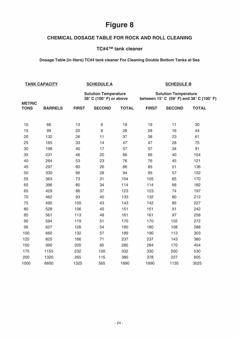
The quantities of chemicals required to achieve satisfactory rock and roll cleaning are shown followingthis dialogue, in Figures 8 and 9.
Schedule A of Figure 8 gives the quantities required when heating facilities enable the solution to be raisedabove 38° C (100° F).
Schedule B of Figure 8 gives the quantities required when heating facilities are not available and thecleaning solution is maintained between 15° C (59° F) and 38° C (100° F). Below this temperature,effectiveness is reduced.
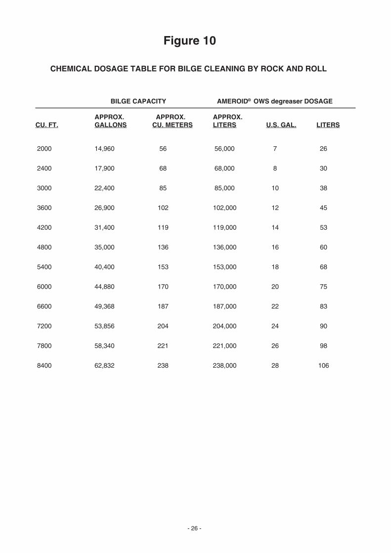
B. Bilges
Determine the amount of water required to fill the bilge to a level which provides complete coverage ofall areas requiring cleaning. Based on the amount of water required, determine from Figure 10 thenecessary dosage of AMEROID® OWS degreaser.
Example:
1. Bilge area is 23 x 23 meters (75 x 75 feet). Average depth of the water is 0.3 meters (1 foot). The totalcubic meters of water in the bilge equals 23 x 23 x 0.3 or 159 cubic meters (5625 cubic feet). Referto Figure 10 for the closest dosage of the selected product.
2. The dosage should be distributed at various points in the bilge, directly from the container. Wherenecessary, apply the product directly onto the vertical surface, utilizing a suitable pump to assureadequate distribution.
3. Add the previously calculated amount of seawater to the bilge, and allow the natural motion of thevessel to provide agitation for a minimum of 24 hours.
4. At the end of 24 hours, pump the bilge dry through the oily water separator or to shore reception facility,and as conditions require, repeat the treatment.
- 24 -
Figure 8
CHEMICAL DOSAGE TABLE FOR ROCK AND ROLL CLEANING
TC#4™ tank cleaner
Dosage Table (in liters) TC#4 tank cleaner For Cleaning Double Bottom Tanks at Sea
TANK CAPACITY SCHEDULE A SCHEDULE B
Solution Temperature Solution Temperature 38° C (100° F) or above between 15° C (59° F) and 38° C (100° F)
METRICTONS BARRELS FIRST SECOND TOTAL FIRST SECOND TOTAL
10 66 13 6 19 19 11 30
15 99 20 8 28 28 16 44
20 132 26 11 37 38 23 61
25 165 33 14 47 47 28 75
30 198 40 17 57 57 34 91
35 231 46 20 66 66 40 104
40 264 53 23 76 76 45 121
45 297 60 26 86 85 51 136
50 330 66 28 94 95 57 152
55 363 73 31 104 105 65 170
60 396 80 34 114 114 68 182
65 429 86 37 123 123 74 197
70 462 93 40 133 132 80 212
75 495 100 43 143 142 85 227
80 528 106 45 151 151 91 242
85 561 113 48 161 161 97 258
90 594 119 51 170 170 102 272
95 627 126 54 180 180 108 288
100 660 132 57 189 190 113 303
125 825 166 71 237 237 143 380
150 990 200 85 285 284 170 454
175 1155 232 100 332 330 200 530
200 1320 265 115 380 378 227 605
1000 6600 1325 565 1890 1890 1135 3025

- 25 -
Figure 9
CHEMICAL DOSAGE TABLE FOR ROCK AND ROLL CLEANING
DREW™ TC SEA tank cleaner
Dosage Table (in liters) DREW TC SEA tank cleaner For Cleaning Double Bottom Tanks at Sea
Tank CapacityMetric Minimum Normal MaximumTons Barrels First Second Total First Second Total First Second Total
2.5 17 1 1 2 3 1 4 4 2 6
5 33 3 1 4 5 3 8 7 5 12
10 66 5 3 8 11 5 16 14 10 24
15 99 8 4 12 16 8 24 21 15 36
20 132 10 6 16 22 10 32 28 20 48
25 165 13 7 20 27 13 40 35 25 60
30 198 16 8 24 32 16 48 42 30 72
40 264 20 12 32 43 21 64 56 40 96
50 330 25 15 40 53 27 80 70 50 120
75 495 40 20 60 80 40 120 105 75 180
100 660 53 27 80 105 55 160 140 100 240
200 1320 105 55 160 215 105 320 280 200 480
250 1650 133 67 200 265 135 400 350 250 600
300 1980 160 80 240 320 160 480 420 300 720
400 2640 215 105 320 425 215 640 560 400 960
500 3300 265 135 400 535 265 800 700 500 1200
600 3960 320 160 480 640 320 960 840 600 1440
700 4620 375 185 560 745 375 1120 980 700 1680
800 5280 425 215 640 855 425 1280 1120 800 1920
900 5940 480 240 720 960 480 1440 1260 900 2160
1000 6600 535 265 800 1065 535 1600 1400 1000 2400
- 26 -
Figure 10
CHEMICAL DOSAGE TABLE FOR BILGE CLEANING BY ROCK AND ROLL
BILGE CAPACITY AMEROID® OWS degreaser DOSAGE
APPROX. APPROX. APPROX.CU. FT. GALLONS CU. METERS LITERS U.S. GAL. LITERS
2000 14,960 56 56,000 7 26
2400 17,900 68 68,000 8 30
3000 22,400 85 85,000 10 38
3600 26,900 102 102,000 12 45
4200 31,400 119 119,000 14 53
4800 35,000 136 136,000 16 60
5400 40,400 153 153,000 18 68
6000 44,880 170 170,000 20 75
6600 49,368 187 187,000 22 83
7200 53,856 204 204,000 24 90
7800 58,340 221 221,000 26 98
8400 62,832 238 238,000 28 106

- 27 -
4. DIRECT INJECTION METHOD AND HOT WATER CLEANING
A. Direct Injection Method
In this method undiluted chemical cleaner is injected into the seawater at a predetermined rate on thepressure side of the tank cleaning manifold or wash line on deck. Together with the seawater from the tankcleaning pump, it passes into the tank via the fixed or portable tank cleaning machines. This method hasthe advantage that the chemical can be introduced into hot tank cleaning water at a precisely calculatedrate. An exact estimate of the chemical requirement can be made before commencing cleaning. It alsoreduces time and manpower for most tank cleaning jobs. The chemical feeding rate is usually 1 liter per 1ton of water used (0.1%), but can be increased to 5 (or more) liters per ton of water (0.5%) when very dirtytanks are to be cleaned. When light cleaning is required, 1 liter per 2 tons (0.05%) of water may be adequate.
NOTE: 1 metric ton = 1000 kg = 1000 liters1 long ton = 1016 kg = 1010 liters
B. Hot Water Cleaning
Hot water almost always improves the chemical action (except with drying oils and waxy crude oils) andaccelerates the chemical cleaning process. As a general rule, the hotter the cleaning water, the better andmore thorough the cleaning action of the chemical. Most oils are easier to detach from the tank sides underthe influence of heat and if kept hot, can be made to flow continuously until they are removed from the tankwithout adhering to the bottom plates.
Two exceptions to the above are:
• Semi-drying and drying oils• High wax content crude oils
It is imperative that the residues of the above oils be initially flushed from the tank by cold washing as soonas possible after discharge of the cargo. Oxidation and polymerization will cause drying and semi-dryingoils to quickly harden to create a tough, tenacious, leathery coating which is very difficult to remove. Longexposure to circulating air enhances this reaction and causes the film to be even tougher and moreadhesive. A cold preclean wash in this case is essential.
A good guide as to whether a hot or cold preclean wash should be given in the case of crude mineral oils,is indicated by the temperature at which the oil has been transported. If the cargo has required heating, thengenerally the tanks will require a cold preclean mechanical wash. The pour point of the oil can sometimesbe a guide to its wax content. Generally, high wax content oils are those with a pour point above 20°C (68°F).It should always be remembered that for a high wax content oil with a high pour point and low API number,heat should never be applied to the tank before the cold preclean wash. If heat is applied, the chances arethat the more volatile fractions will be flashed off leaving the heavier, more tenacious residues adhering tothe tank sides. If it is not certain whether a cargo is a drying or semi-drying oil, consult the cargo loading/handling specifications held by the ship’s Master. If uncertainty still exists, preclean with cold water.
5. DETERMINATION OF THE MOST APPROPRIATE CLEANING PROCEDURE
Accumulate all preliminary information from the vessel and complete the questionnaire (Appendix G, page 89)which will aid the selection of the most appropriate program to determine the cleaning method best suited to theproblem. A cross-reference guide can be found at the end of the manual (Appendix D, page 61) which lists the mostcommon products and chemicals carried today and the most effective method of removing their residues inreadiness for the next cargo.
6. CLEANING CARGO LINES AND SLOP TANKS
As the valves and line arrangements differ considerably from vessel to vessel, it is impossible to give preciseinstructions for this cleaning procedure. Each vessel’s lines should be cleaned to the specific instructions of theofficer in charge. The following is a general outline procedure which can be modified to suit most vessels. Forvessels out-fitted with Crude Oil Washing, refer to the Crude Oil Washing Manual onboard.
Initially, all main cargo tanks and pipes should be stripped to the slop tanks before washing is commenced. Thisprocess should be helped by flushing the system with seawater and stripping through the main stripping lines.

- 28 -
It is recommended that the operation be performed from the forward tanks working back through the system. Themain valves should be opened as little as possible to avoid starving the pumps and losing suction. With this processcompleted, all free oil should be removed from the main and stripping lines as well as ensuring that the tanks areas nearly dry as possible. The same operation should be repeated for any other lines in the tank, i.e., the athwartshiplines. When this has been completed, the stripping pump filters should be inspected and cleaned if necessary.These filters should be kept clean during the tank cleaning program in order that the correct rate of stripping ismaintained throughout. The cleaning process should be continued and the chemical solution passed through boththe main and stripping lines. Finally, the lines are flushed with water.
A temporary line should be connected between the tank cleaning line and the deck lines with an outlet to the sloptanks in order that the loading and discharge lines and manifolds can be cleaned. The tanks and lines should finallybe rinsed with fresh water to remove the last traces of the sediment, detergent and salt. All bottom, deck main andstripping lines as well as valves, filters, etc., should now be clean.
7. DETERMINING THE NUMBER OF TANK CLEANING MACHINE CYCLES FOR EACH CLEANING JOB
If specific data pertaining to the vessel’s construction is not available, but is known that the vessel is equipped withBUTTERWORTH1 K type tank cleaning machines, an estimate of the required minimum number of tank cleaningmachine cycles can be made by using the following formula:
• Minimum number of tank cleaning machine cycles = 1.5 dwt. (Essentially 1.5 times the square root of thevessels dead weight tonnage.)
The number of tank cleaning cycles derived from the above formula is fairly accurate for vessels that havecarried light to medium crude oil cargoes that have not been reduced, vacuum flashed or topped before theywere loaded into the tanks.
• Medium to heavy crude oils will require the number derived from the formula to be multiplied by 1.25.
Minimum number of tank cleaning machine cycles = 1.5 dwt x 1.25.
• Heavy crude oils and other waxy cargoes will require the formula to be multiplied by 1.5.
Minimum number of tank cleaning machine cycles = 1.5 dwt x 1.5.
As an example, if we take a tanker of 30,000 dwt, the following will be the minimum of machine cycles requiredcommensurate with good cleaning:
1. Light Crude Oil (N = Minimum number of tank cleaning machine cycles.)
N = 1.5 dwtN = 1.5 30,000N = 1.5 x 173N = 260
2. Medium Crude Oil
N = 1.5 dwt x 1.25N = 1.5 30,000 x 1.25N = 1.5 x 173 x 1.25N = 325

- 29 -
3. Heavy Crude Oil
N = 1.5 dwt x 1.5N = 1.5 30,000 x 1.5N = 1.5 x 173 x 1.5N = 390
The above is only a guide to the specific number of cycles required when using BUTTERWORTH1 K tank cleaningmachines. The actual number depends upon many other extraneous factors. However, from the above calculationsa fairly accurate assessment of the quantity of chemical to be used during the entire cleaning operation can beestimated. Using the information given on page 2 of the manual, it can be seen that at a pressure of 12 bar (176psi) (12.3 kg/cm2) a total of 12 tons of seawater is used on each BUTTERWORTH K tank cleaning machine cycle.
The strength of solution (seawater and tank cleaning chemical) depends upon these factors:
• The type of residue to be removed• The degree of dirtiness of the tanks• The degree of cleanliness required for the next cargo• The temperature of the cleaning solution
Generally for the direct injection method, a solution strength of 0.1% is sufficient. The quantity of chemical requiredusing this method is referred to as Qd. (Quantity Direct Injection).
Below is shown one method of calculating the quantity of tank cleaner required using 0.1% solution for a tanker of30,000 dwt:
a. The total quantity of chemicals required (Qd) to clean the tanks of a vessel carrying light crude oil is:
Total number of machine cycles (from No. 1 above) = 260. Total quantity of wash water used at 12 tonsper cycle = 12 x 260 = 3120 tons.
Solution concentration selected is 0.1% (1 liter per ton of water) Therefore, total chemical cleanerrequired:
Qd = 3120 x 1 literQd = 3120 liters
b. For medium crude oil cleaning, the quantity of chemical required will be:
Qd = 3120 liters x 1.25 = 3900 liters
c. For heavy waxy crude oil, the quantity of cleaner required will be:
Qd = 3120 liters x 1.5 = 4680 liters
If heavy fouling of the tank has taken place and the residues are difficult to remove, the solution strength shouldbe increased. This will, of course, increase the quantity of cleaning chemicals in direct ratio.
NOTE: The above computations are specific for BUTTERWORTH K tank cleaning machines.
The BUTTERWORTH SK tank cleaning machine has a maximum capacity of 53 cubic meters per hour with washcycle times from 17 to 41 minutes, depending upon water inlet pressure.
The BUTTERWORTH SSK tank cleaning machine has a maximum capacity of 75 cubic meters per hour with similarwash cycle times, depending upon inlet pressure.
To calculate the quantity of chemical required using the BUTTERWORTH SK tank cleaning machine as well as anyother type of tank cleaning machine, it is recommended that use be made of the method described on pages 31and 32, in conjunction with the Tank Cleaning Product Cross-Reference Table in Appendix D.
- 30 -
8. CLEANING BALLAST TANKS
A. Removing mud
Mud and silt buildup can occur in a active ballast tank within a relatively short amount of time. If left in thetank, this buildup can result in a loss of cargo carrying capacity and even an increase in fuel consumption.
To minimize this problem, MUD CONDITIONERTM ballast tank water treatment should be used on a regularbasis to treat the ballast water as it enters the ballast tank. The recommended level of treatment of MUDCONDITIONER treatment is 20-30 liters per 1,000 tons of ballast water.
In situations where the mud and silt has accumulated, an increase in dosage of MUD CONDITIONERtreatment is required. For this, a dosage of 100-200 liters per 1,000 tons of ballast water is needed. Also,good agitation is needed in order to allow the MUD CONDITIONER treatment to penetrate the mud. A firehose or portable tank cleaning machine can be used.
B. Removing Soft Coatings
The thickness that these products are applied will determine the method of cleaning. For those under 10mils, EDGE® heavy duty cleaner can be hand sprayed, allowed to soak, and then followed with a waterwashing.
If the coating is greater than 10 mils, hand scraping of the material may be necessary. Once this has beenaccomplished, hand spray EDGE heavy duty cleaner, allow to soak and follow with a water washing.
Any oil film remaining in either case should be removed by adding 0.5% LACTM liquid alkaline cleaner andfill the tank with seawater to 70% capacity. Allow it to rock-and-roll for a minimum of 24 hours.

- 31 -
CHAPTER VIII
THE CALCULATION OF CHEMICAL QUANTITIES AND CLEANING TIMES
The quantity of chemical to be used and the time required for the selected cleaning method should be calculatedfor each separate cleaning program phase. Each calculation is dependent upon the following factors:
• Number and size of tanks to be cleaned
• Quantity of water and pressure available for tank cleaning system
• Complexity of tank internals and position of frames, etc.
• Number and condition of tank cleaning machines available (fixed and portable)
• Cycle time at the available water pressure for the tank wash machines
• Degree of cleanliness required, i.e., upgrading or cleaning for an edible cargo, to gas free or for hot work
1. CLEANING TIME CALCULATIONS
The tank cleaning pump delivery rate and the output of the tank cleaning machines will determine the number ofmachines that can be used simultaneously. Most portable tank cleaning machines will use approximately 25-30tons of water/hour (12-15 tons/cycle), but this figure should always be checked. The above will determine thenumber of tanks that can be cleaned at the same time. The time to clean the calculated number of tankssimultaneously will be dependent on the cycle time of the machines, the number of washes required and the numberof drops (in the case of portable machines) required to cover completely the depth of the tanks and the internalstructures.
For example, to clean a single tank using 4 machines with 3 drops at 4 meters each with the last drop just abovethe tank bottom plus one extra washing of the bottom with a machine cycle time of 30 minutes, the total time requiredper tank is 4 x 30 min = 2 hours, (i.e., each drop is one cycle duration plus one extra washing of the bottom plates).
As the tanks increase in size, the number of drops necessary also increases. For VLCC’s as many as 6 or 7 dropsmay be required.
2. QUANTITY OF CHEMICAL REQUIRED
A. Direct Injection Method
Using the above information, the quantity of chemical required per tank can be calculated.
To calculate the quantity of chemical (Qd) necessary, the following information is required:
(P) = Quantity of chemical to be used per ton of water (1 liter/ton, i.e., solution strength 0.1%)(M) = Number of machines to be used per tank(C) = Output of each machine (tons/hour)(T) = Total time to clean the tank (hours)
Using the above data we have:
i.e., Qd = P x M x C x T Qd = 1 x 4 x 25 x 2 = 200 liters/tank
For a total of 12 similar-sized tanks to be cleaned, the chemical required is 12 x 200, i.e., 2,400 litersDREW™ TC SEA tank cleaner or TC#4™ tank cleaner.
- 32 -
B. Recirculation Method
For this method, a solution of seawater and tank cleaning chemical is mixed in a slop or cargo tank. Thesolution strength depends upon the quantity of water required to circulate the system and maintain adequatesuction at the pumps.
The quantity of chemical cleaner required for this method is referred to as: Qr (Quantity RecirculationMethod). To establish the quantity of tank cleaning chemical (Qr) required, use the following formula:
Qr = Solution strength (1.25 to 1.4 x P) x Tons of water (1.5 dwt X C)
In the recirculation cleaning, the very nature of the method does not lend to efficient use of the product, andeach batch of solution mixed will not perform as efficiently as will the cleaner when introduced directly intothe tank cleaning water. For this reason, the total quantity of product estimated should be increased bybetween 25% and 40% over the direct injection method to produce equivalent results.
Therefore, in the example given on page 28 and 29 for the cleaning of 30,000 dwt tanker using a 0.1%solution of tank cleaner, the calculated total quantity required, 3,120 liters in this case, should be increasedby, on average, 33% to obtain the correct quantity of product necessary to conduct efficient recirculationcleaning, i.e., liters required for cleaning a 30,000 dwt tanker using the recirculating method is as follows:
Qr = 3,120 x 1.33 = 4,150 liters
The solution concentration will be increased accordingly.
For each recirculation process, it has been found that in order to maintain adequate suction and supply andreturn to and from the tank being cleaned, 250 tons of solution should be made up. However, this quantitycan be varied in order to match the proposed number of batches and the solution strength required.
After each recirculation cycle is completed, the chemical solution containing the residue of the cleaningprocess should be removed to a slop tank for separation and the procedure repeated using a fresh batchof solution. The temperature of the solution should be maintained at 40° C (104° F) or above if possible,preferably at 80° C (176° F). (See the Tank Cleaning Product Cross-Reference Tables in Appendix D.)
C. Rock and Roll Method
The quantity of product required to clean by this method is given in either Figure 8 or 9 depending on whetheryou are using DREW™ TC SEA tank cleaner or TC#4™ tank cleaner.
D. Hand Spray and Atomization Method
After cleaning by either direct injection, recirculation or rock and roll methods, spot cleaning may be requiredusing hand sprayed full strength chemical (DREW TC SEA tank cleaner or TC#4 tank cleaner) on any hiddenspots which have not been satisfactorily cleaned. After suitable soaking time, the chemical and residuesshould be washed off by hand hosing.
The quantity of preferred chemical (DREW TC SEA tank cleaner or TC#4 tank cleaner) required for undilutedapplication for hand spray or lance injection can be verified by the following formula:
Required chemical in liters = tank surface area (m2) (tank bottom, sides, frames, etc.) x 0.2
i.e., Area m2 x 0.2 = liters of product (DREW TC SEA tank cleaner or TC#4 tank cleaner)
- 33 -
Alternatively:
Chemical in liters = volume of tank (m3) x 0.15. If only light contamination of the tank surfaces exists,the above quantities can be reduced by up to 30%.
The above cleaning quantity data is recommended for small cargo tanks only, it being almost physicallyimpossible to clean large tanks by hand spray or lance injection.
After cleaning the tank, the accumulated sediment and rust should be removed from the tank bottom. Thisis normally achieved by hand mucking the tanks by the vessel’s crew using mops, buckets, etc.
- 34 -
CHAPTER IX
INTRODUCTION TO COW AND IGS
1. WHAT ARE COW AND IGS?
The following gives a brief description of crude oil washing (COW) and inert gas systems (IGS). The aim is to reducethe likelihood of accidental explosions and minimize the amount of pollution from oily ballast water. This, of course,has a direct effect upon the discharge of slops from the tank cleaning or the tank washing process.
COW is a tank cleaning system in which cargo (crude oil) is used as a washing agent as opposed to water andchemicals. Oil residues are sprayed by fixed cleaning machines so that they dissolve back into liquid suspensionand are discharged with the cargo, not later with the ballast. This also increases the cargo out-turn from the vessel.
Other advantages of using COW include: reduced tank corrosion, quicker preparation for dry docking and repair,and reduced need for oily water reception facilities.
Offsetting these are certain disadvantages, among which are: COW is not possible with some crudes; it requirestrained and qualified operatives; it may increase hydrocarbon emissions with the attendant risk; it increases thedischarge time at the terminal; and it is costly in terms of installation and maintenance.
Overall, though, it is the most economic alternative to meet the Marine Pollution Convention (MARPOL) and hasbeen chosen by the great majority of operators of existing crude oil tankers.
Due to terminal schedules and demurrage costs, 100% crude oil washing is not always possible. This necessitatesa return to water washing with chemicals, especially when gas freeing for maintenance or changes in cargo.
Water washing is accomplished with the fixed COW machines. These machines have a larger capacity in tons perhour than portable machines and, by design, have no heater in the system.
While COW was originally adopted for commercial reasons (greater cargo out-turn) inert gas has always had amajor safety function. Initially used to prevent explosions in partially filled tanks of hydrocarbons (removing one sideof the fire triangle of fuel, oxygen, and ignition source) it came to prominence as the major preventative measurefor tankers while washing with water.
Water washing of tanks was found, following three VLCC explosions, to create large electrostatic charges in tanksand the use of inert gas prevented an explosion from occurring. Obviously COW creates much larger quantitiesof hydrocarbon gas and the use of inert gas (IG) is a necessity.
Crude oil washing was first adopted by tanker owners in the early 1970’s basically for commercial reasons,achieving a greater outturn of cargo and greatly reducing the quantities of oil retained onboard as part of the loadon top operation, eliminating problem sludge buildup in tanks and reducing corrosion. Through the various IMCO,MARPOL, and TSPP (Tanker Safety and Pollution Prevention) conventions, crude oil washing has now becomeaccepted as the alternative to segregated ballast tanks (SBT) in an effort to minimize oil pollution from tankers, andit is mandatory in the UK, U.S.A. and Holland.
Apart from the specific requirements for COW equipment, including suitable washing machines at strategiclocations in the tanks and an effective stripping system, an inert gas system is crucial to lower the oxygen contentand eliminate the risks of explosion. Crude oil washing is not permitted without an inert gas system. For each shipthere will be predetermined procedures for crude oil washing and only properly qualified personnel with experiencein participating in crude oil washing programs and having full knowledge of the ship’s systems and its operation willbe able to carry it out. In this respect, it should not be forgotten that crude oil washing is undertaken during cargodischarge, a busy enough time for any tanker crew, and the work load could be so much increased that safety couldbe compromised.
- 35 -
2. CRUDE OIL WASHING (COW)
Crude oil carrying vessels have traditionally cleaned their tanks by washing with jets of water. Such methods ofwashing produce large quantities of oil in water which must be separated. The separation process is complicatedby the oily water emulsions which are produced during the washing. This has led to the retention onboard ofquantities of water along with the slop oil, recovered by the Load On Top procedure. In the Load On Top procedure,new cargo is mixed with the retained slop oil/water mixture, and the combined product is discharged as cargo atthe receiving port.
After discharge of a cargo, a ship’s tanks which have held crude oil, usually contain deposits of sediment on thetank bottoms and other horizontal surfaces. This sediment, which has settled from the cargo, consists mainly ofwaxy and asphaltic substances. If allowed to remain, it will build up after several voyages and impede drainage andreduce the cargo carrying capacity. All oil and sediment must be removed from the cargo tanks which are to be usedfor clean ballast.
In crude oil washing, part of the cargo (containing all of the volatile components) is circulated through the fixed tankcleaning equipment to remove, by impingement, the waxy asphaltic deposits. This is normally carried out duringdischarge. Crude oil washing has proved to be more effective than water washing for this purpose, because thecrude oil acts to disperse and suspend sediments and tends to restore the cargo to its as-loaded condition. If, dueto insufficient impingement velocity or the existence of shaded areas in a tank, thorough cleaning is not achieved,the use of AMERGY® 222 fuel oil conditioner will greatly assist the breakdown and removal of waxy deposits. If avessel is experiencing difficulty in obtaining good results in their COW operations, it is recommended that AMERGY222 conditioner be added to assist in the break up of tank residues before pumping the oil ashore. The AMERGY222 conditioner should be added at a ratio of 1 liter AMERGY 222 conditioner to 10 tons of cargo remaining onboardat the commencement of the crude oil washing. Before adding AMERGY 222 conditioner or any other chemical toa crude oil cargo, it must be established whether or not the refinery can handle the product in their refining process.
After crude oil washing, both water washing of tank bottoms and flushing of cargo lines are required if the tank isto receive clean ballast or if gas freeing is required for any reason.
Without crude oil washing, large quantities of water are required to clean cargo tanks. The resulting oily mixturesand emulsions, together with dirty ballast, must be retained onboard until they have been settled and separated.This process is much simplified when tanks have first been crude oil washed. The oil content of dirty ballast is greatlyreduced as a result of this procedure. Cargo tanks which are to be used for clean ballast need only a short rinsewith water after crude oil washing. However, pumps and lines must be thoroughly flushed with water. Tanks whichare not required for ballast need not be water washed during normal trading as sediment can be kept under controlby crude oil washing. Cargo tanks of segregated ballast vessels fall into this category.
By this method, not only is the quantity of residue in the ship greatly reduced, but the quantity of oil/water mixtureproduced is much smaller and the operation itself is shortened. These factors reduce the potential for pollution.
Crude oil washing is carried out by means of properly designed, permanently piped, fixed in place tank cleaningmachines. All, or most, of these will be high capacity type (60 cubic meters per hour or greater). Crude oil washingis carried out during cargo discharge or may be, to a limited extent, carried out at sea between discharge ports. Itmust be completed before departure from the final discharge port. Ballast should not be loaded into a tank that hasnot been crude oil washed where the system is available. Clean ballast should be loaded only into tanks that havea water rinse or flush after crude oil washing.
In terms of equipment, there are perhaps a half a dozen major manufacturers. Most produce single nozzlemachines, or guns which are programmable so as to devote all their cycle time to those areas which usually aremore affected by residue. However, to effect this washing procedure, each machine deck control unit must beoperated once, perhaps twice, during the wash cycle.
The alternative approach is the twin nozzle machine which overall entails about half the number of manualoperations to carry out a wash program and relies on “two shots” per revolution.
As essential to satisfactory crude oil washing as the installed tanks washing machines, is the design and installationof a stripping system that is capable of maintaining the tank bottom free of standing oil during the bottomwashingoperation.
- 36 -
Hydraulic stripping eductors have been found to be the best equipment for this service. To assure continued reliableperformance without undue maintenance, eductors are specified to have bodies of nickel-aluminum-bronze andnozzles of monel metal.
3. LOAD ON TOP METHOD (LOT)
Usually any tanker or oil bulk ore (OBO) vessel which has carried a crude oil cargo will depart the discharge portwith several of its tanks, holds or double bottoms ballasted.
Any empty tanks, if not previously crude oil washed, should be cleaned using the usual processes. These tanks,once cleaned, are filled with ballast water and the original tanks, first ballasted, are emptied and cleaned. In thisway, the vessel arrives at its loading port solely with clean ballast to discharge. Disposing of the oily water resultingfrom the cleaning operation and the contaminated oily ballast water, poses a problem because the maritime lawtoday permits oil discharge of one fifteen thousandth (one ton of oil for each 15,000 dead weight tons) of the vessel’stonnage to be discharged during the cleaning operation. For example, a vessel of 30,000 dwt is permitted todischarge a maximum of only 2 tons of oil during any one cleaning operation.
Since oil generally weighs less than water, it will gradually float to the top of the water in the slop tank. It is possibleon a long voyage to rely on the natural process of separation (some of today’s residual oils are much heavier thanseawater and those with an API number of 10, i.e. SG 1.00 or above, are impossible to separate with the LOTsystem). With the LOT process, the bulk of the original ballast and cleaning water can be discharged to the sea.The water is discharged and the oil removed by the cleaning is retained, thus minimizing pollution. A residue of oilmixed with water remains in the tank.
Using the LOT system, the residues from the washed tanks are gathered together in a slop tank. This is usuallya special tank or a designated cargo tank. After a period of settling in the slop tank, more water can be dischargedleaving a final residue of oil and oil partially contaminated with seawater. The next cargo is loaded on top of thisresidue, and the entire mixture is pumped ashore to the refinery at the next discharge port where the sea water isseparated from the oil physically and/or chemically in a desalter.
The salt water content of the crude oil cargoes poses a continuing problem for oil refineries. The elimination of waterfrom cargo only tanks and the reduction in the quantity of slops after crude oil washing, reduces salt watercontamination of the subsequent cargo.
In the Load On Top procedure, the ship’s capacity to load new cargo is reduced by the weight of the retained slopsand sediments on board. A typical oil/water quantity for a 215,000 dwt tanker after water washing is 1,200/2,300tons, and for a vessel of the same size on which a full crude oil wash is carried out, a typical figure is 360 tons. Thisincreases the effective cargo capacity of the vessel.
The Load On Top procedure has been recognized for several years as the most effective method of reducing oilpollution at sea. About 2 million tons of oil each year are recovered using the LOT method.
4. INERT GAS
The presence of flammable vapors in the cargo tanks of tankers has led to the development of a system wherebyinert gas is used as a smothering medium on top of the crude oil. Inerting is essential if crude oil washing is to beconducted during the discharge of a cargo. This is the time at which the gas/air mixture proportions can rapidlychange, one condition producing a super-rich mixture and another a blend which is potentially highly explosive.
IMO regulations specify that all tankers above 40,000 dwt with high capacity crude oil washing facitlities are requiredto be fitted with an inert gas system.
A. Inert Gas Production
Inert gas is produced either from the washed flue gas of a boiler or by a special gas generator. Sometimes,when hazardous cargoes that react with air are carried, it is necessary to blanket them with an inert gas,i.e. nitrogen or other nonreactive gas, to prevent reactions of the chemical which could cause seriousdamage.
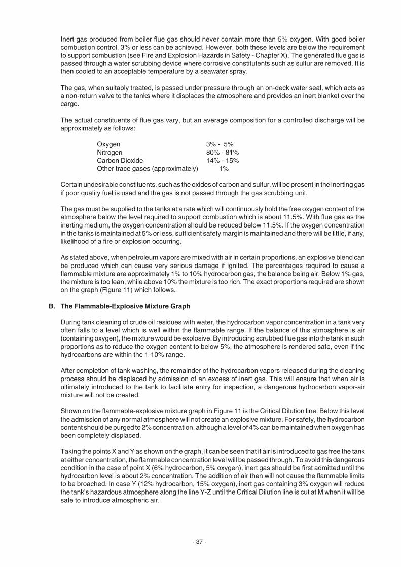
- 37 -
Inert gas produced from boiler flue gas should never contain more than 5% oxygen. With good boilercombustion control, 3% or less can be achieved. However, both these levels are below the requirementto support combustion (see Fire and Explosion Hazards in Safety - Chapter X). The generated flue gas ispassed through a water scrubbing device where corrosive constitutents such as sulfur are removed. It isthen cooled to an acceptable temperature by a seawater spray.
The gas, when suitably treated, is passed under pressure through an on-deck water seal, which acts asa non-return valve to the tanks where it displaces the atmosphere and provides an inert blanket over thecargo.
The actual constituents of flue gas vary, but an average composition for a controlled discharge will beapproximately as follows:
Oxygen 3% - 5%Nitrogen 80% - 81%Carbon Dioxide 14% - 15%Other trace gases (approximately) 1%
Certain undesirable constituents, such as the oxides of carbon and sulfur, will be present in the inerting gasif poor quality fuel is used and the gas is not passed through the gas scrubbing unit.
The gas must be supplied to the tanks at a rate which will continuously hold the free oxygen content of theatmosphere below the level required to support combustion which is about 11.5%. With flue gas as theinerting medium, the oxygen concentration should be reduced below 11.5%. If the oxygen concentrationin the tanks is maintained at 5% or less, sufficient safety margin is maintained and there will be little, if any,likelihood of a fire or explosion occurring.
As stated above, when petroleum vapors are mixed with air in certain proportions, an explosive blend canbe produced which can cause very serious damage if ignited. The percentages required to cause aflammable mixture are approximately 1% to 10% hydrocarbon gas, the balance being air. Below 1% gas,the mixture is too lean, while above 10% the mixture is too rich. The exact proportions required are shownon the graph (Figure 11) which follows.
B. The Flammable-Explosive Mixture Graph
During tank cleaning of crude oil residues with water, the hydrocarbon vapor concentration in a tank veryoften falls to a level which is well within the flammable range. If the balance of this atmosphere is air(containing oxygen), the mixture would be explosive. By introducing scrubbed flue gas into the tank in suchproportions as to reduce the oxygen content to below 5%, the atmosphere is rendered safe, even if thehydrocarbons are within the 1-10% range.
After completion of tank washing, the remainder of the hydrocarbon vapors released during the cleaningprocess should be displaced by admission of an excess of inert gas. This will ensure that when air isultimately introduced to the tank to facilitate entry for inspection, a dangerous hydrocarbon vapor-airmixture will not be created.
Shown on the flammable-explosive mixture graph in Figure 11 is the Critical Dilution line. Below this levelthe admission of any normal atmosphere will not create an explosive mixture. For safety, the hydrocarboncontent should be purged to 2% concentration, although a level of 4% can be maintained when oxygen hasbeen completely displaced.
Taking the points X and Y as shown on the graph, it can be seen that if air is introduced to gas free the tankat either concentration, the flammable concentration level will be passed through. To avoid this dangerouscondition in the case of point X (6% hydrocarbon, 5% oxygen), inert gas should be first admitted until thehydrocarbon level is about 2% concentration. The addition of air then will not cause the flammable limitsto be broached. In case Y (12% hydrocarbon, 15% oxygen), inert gas containing 3% oxygen will reducethe tank’s hazardous atmosphere along the line Y-Z until the Critical Dilution line is cut at M when it will besafe to introduce atmospheric air.

- 38 -
Figure 11
FLAMMABLE-EXPLOSIVE MIXTURE GRAPH
LOWER FLAMMABLE LEVEL1% HYDROCARBON VAPOR
UPPER FLAMMABLE LEVEL10% HYDROCARBON VAPOR
SUPER RICH HYDROCARBONGAS ZONEFLAMMABLE
ZONE
MIXTURETOO LEANTO SUSTAINCOMBUSTION
ADMISSION OF INERT GAS (5% O2)
OXYGEN LEVEL TOO LOW TOSUSTAIN COMBUSTION
0 2 4 6 8 10 12 14 16
% HYDROCARBON GAS IN ATMOSPHERE
% O
XY
GE
N IN
AT
MO
SP
HE
RE
18
16
14
12
10
8
6
4
2
M
Y
20
22
CRITICAL DILUTION LINE
LINE SHOWING OXYGEN CONCENTRATIONIN TANK ON ADMISSION OF AIR
ADMISSION OF INERT GAS (3% O2 CONCENTRATION)
LINE SHOWING OXYGEN CONCENTRATIONIN TANK ON ADMISSION OF AIR
X

- 39 -
C. Crude Oil Grades
Petroleum products are divided into 3 groups depending on their volatile properties.
Class A petroleum is highly volatile and is dangerous due to the fact that it can easily create an over-richmixture in a storage tank. This could, on admission of atmospheric air, create a flammable-explosivemixture. During loading or discharge of Class A products this probability is a particular problem, and inertingshould be maintained throughout these operations.
Class B petroleum gives off only moderate amounts of vapor and is not considered as dangerous as ClassA. Nevertheless, Class B materials should be treated with caution especially if heat has been applied tothem, since their volatile properites will be greatly increased.
Class C petroleums generally give off little vapor unless heated to above their flash point.
D. The Inert Gas System
A typical boiler flue gas inerting system is shown in Figure 12, together with a deck seal, Figure 13, thathas been designed to meet the IMO requirements.
The flue gas inerting system consists of the following main components:
• Trunking fitted with remote controlled regulating valves to convey the gas to the processing unit at thecorrect rate.
• The filters and scrubbing unit which remove the impurities such as soot particles and carbon monoxide.
• Seawater pumps and lines to provide cooling and scrubbing water.
• Large fans to convey the cooled gas to the tanks through the deck supply lines. The fans also can beused to supply atmospheric air to the tanks via a cross-over valve to accomplish gas freeing.
• An on-deck water seal backed up with vacuum/pressure breakers to prohibit the blow-back of gasesfrom the tanks into the machinery spaces.
• Control panels, situated in the engine room, cargo control room and bridge together with oxygenanalyzing equipment, safety devices and alarms. Inerting gas must be fully purged from a tank beforepersonnel are allowed to enter. If the inerting gas has not been fully purged, the lack of oxygen will causedeath in a very short time.
For diesel vessels, where good quality stack gas it not available, there is an inert gas generator. Itconsists of one unit that:
• Burns fuel directly under combustion controls to minimize oxygen and carbon monoxide.
• Cools and scrubs the combustion gases.
• Conveys the inert gas (or atmospheric air via crossover) to deck water seal and systems.
The advantage of an inert gas generator is consistant good quality gas regardless of vessel operatingmode.
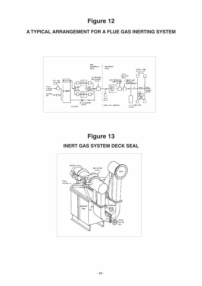
- 40 -
Figure 12
A TYPICAL ARRANGEMENT FOR A FLUE GAS INERTING SYSTEM
Figure 13
INERT GAS SYSTEM DECK SEAL

- 41 -
CHAPTER X
SAFETY
1. ENTRY INTO CARGO TANKS AND ENCLOSED SPACES
Cargo tanks which have contained a volatile oil are very likely to contain toxic vapors and/or explosive mixtures.Furthermore, tanks which are cathodically protected and have been ballasted can have reserves of hydrogen gaspresent which should be dispersed by ventilation before entering. Oxygen deficiency can occur in tanks due tocorrosion resulting from seawater ballast residues remaining in the tank. Oxygen also may be depleted by thepresence of sulfides in seawater which tend to oxidize to sulfates. Sulfides are toxic and, like ammonia, areproduced by bacteria (in the seawater), reducing sulfates and nitrogen compounds. Water containing compoundssuch as hydrogen sulfide can be taken on board when ballasting, especially when the vessel is in estuarial waters.
High concentrations of hydrogen sulfide (up to 7,000 ppm), have been found in gas streams leaving ullage portsabove crude tanks. The threshold limit value (TLV) of hydrogen sulfide is currently 10 ppm. American Conferenceof Governmental Industrial Hygienists has proposed lowering the TLV to 5 ppm.
The normal quantity of oxygen in the atmosphere is 21%. A lower oxygen content than this will initially causedrowsiness leading to loss of consciousness which could result in a fall, injury or death. Thus, a tank apparentlysafe because it has been isolated and closed, may be dangerous due to lack of oxygen and, possibly, the existenceof toxic vapors generated by the presence of bacteria. Further, the oxygen can be displaced by other gases orvapors generated from a cargo or the inert gas from an inerting system.
Fresh flue gases contain typically about 200 ppm of mixed nitrogen oxides. After standing for one or two days, thelevel drops to 10-20 ppm. The TLV of nitric oxide is 25 ppm and nitrogen dioxide 3 ppm.
Pump rooms can be a special hazard, as they are the working areas most closely associated with the cargo. Pumproom bilges can be contaminated by leakage from pump glands and pipeline flanges. Volatile vapors given off fromproducts such as benzene or crude oils have the potential to be toxic and can displace the oxygen of the atmospheremaking the compartment dangerous to enter without proper ventilation. Cofferdams similarly can be affected bycargo leakage, possibly via defective weld seams. Both pump rooms and cofferdams, if isolated for long periods,can be deficient in oxygen due to corrosion end products resulting from the reaction of seawater ingress.
Chemical tankers are a particularly dangerous type of vessel due to the vast range of flammable, corrosive or toxiccargoes they may carry. Some toxic substances can be absorbed through the skin and can travel with the bloodto affect vital organs. Great care must be taken when cleaning vessel systems which have carried several differentchemicals to ensure that they are compatible with the cleaning chemicals and that they will not react with each otherin pipelines or slop tanks. When the presence of a toxic, corrosive or flammable substance is suspected, it mustbe tested and rendered innocuous before human contact is made.
The general precautions to take when dealing with dangerous substances are to inert and then gas free or ventilatethoroughly. Ventilation to the bottom of the tank to be entered is to be continued for the duration of the tank inspectionprocedure. Before entering a cargo space or pump room, it is good practice to drain any liquids away from the tanktops or bilges in order that dangerous vapors cannot be derived from their presence. Valves and pipelines shouldnot be opened, as contamination can occur from liquid or vapor remaining in the line. Similarly, cargo pumps shouldalways be flushed through and isolated before they are opened for inspection.
After the discharge of certain chemicals, it may be necessary to flush the lines and pumps with a solvent to ensurethat they are clean and will not cause injury to personnel when opened for inspection. Protective clothing, includinggoggles, gloves and shoes should always be worn when in the proximity of chemical cargoes. Respirators shouldbe used when necessary. The guidelines for safe working practice outlined in the booklets “Tanker Safety Code”and “Tanker Safety Guide” and the corresponding IMO recommendations should always be closely followed whencleaning hazardous cargoes from the tanks of ships.

- 42 -
2. GAS FREEING
Gas freeing is done to ensure that enclosed spaces or tanks may be entered safely or in order to make certain thatthey are not dangerous for carrying out hot work (welding or burning) inside these compartments.
In port, an authorized chemist will issue a gas free certificate after conducting certain tests to prove that any gaspresent is in a concentration below the lower flammable limit and the threshold limit value. As well as being freeof gas, a tank must not contain oil, scale or sludge residues, and any explosive or other toxic hazards must beeliminated before a certificate can be issued. If a tank is to be gas freed for hot work, it is important to ensure thatadjacent tanks are also gas free. In this way, the heat transferred will not be responsible for igniting any flammablegases. Adequate ventilation is essential during the entire time that men are working in tanks that have carriedhazardous cargoes.
3. FIRE AND EXPLOSION HAZARDS
Safety aboard all classes of tankers is of the utmost importance. Most of the risks are eliminated by the designerof the ship and adherence to international, national and company safety regulations. In order to preserve safeworking conditions, care must be taken not only by the vessel’s crew, but by all people (including shore workers)operating the ship. In order to exercise proper care, it is essential that all personnel are well versed in the behavior,characteristics and properties of the liquid cargoes they are handling under the various physical conditions likelyto be met. Fires and explosions are likely to occur when the following conditions are encountered:
• Hydrocarbon or other flammable gas is present in proportion of 1% to 10% in air.
• Oxygen is present in sufficient quantity to support combustion of flammable gases (generally about 11.5%).
• There is an ignition source - usually the flame from a welding oxy-acetylene torch or an electrically ormechanically induced spark.
The above three conditions are quite often represented diagrammatically in the form of a triangle, as shown in Figure14, below.
Figure 14
THE “FIRE” OR COMBUSTION SUPPORT TRIANGLE
FLAMMABLE GAS (FUEL)
AIR (OXYGEN)
IGNITION (SPARK, FLAME)

- 43 -
If any one of the sides of the triangle above is removed, the triangle will collapse and combustion will not be possible.It is the aim of all control methods to eliminate one or more of the sides of the triangle to ensure positive eliminationof the hazard. The elimination is usually achieved in the following ways:
• When discharging or loading a cargo it is usual to inert the tank, thereby eliminating oxygen.
• The hydrocarbon gas accumulation in a tank or compartment is eliminated by gas freeing and testing theatmosphere regularly.
• To eliminate all ignition sources is not easy. Although tanker operation regulations generally stipulate thatmatches and/or cigarette lighters are not to be carried on deck, and any lamp or other electric appliance mustbe spark-proofed, these precautions are only part of a satisfactory program. Further to the above, thefollowing recommendations are usually in force at all times when a tanker is in service:
a. Smoking is permitted only in those places sanctioned by the Master (usually in areas aft of the funnel).
b. Use of aluminum or other light metal objects on deck or in tanks where dangerous flammable gasescould accumulate is strictly prohibited.
c. Handle all metal tools and other equipment in enclosed areas carefully to prevent sparks.
d. Never operate portable radios on deck that are not properly spark-proofed.
e. Never operate any electrical equipment that is not properly grounded.
When cleaning a tank that has carried a volatile oil, it is quite likely that the atmosphere will pass in and out of theexplosive range as the gas is released by the hot or cold cleaning water as it impinges on the oil film and scalesediments. These can absorb and retain quantities of liquid which are released as a vapor. This can increase alean atmospheric mixture of hydrocarbons into the flammable range which can be ignited in the presence of a spark.Sparks can be generated by static electricity from the high velocity droplets of water from a tank washing operation.These water particles will electrically discharge an instant before contact with the tank bulkhead.
If flammable vapor has been released at this location and it is in a concentration between the upper and lowerexplosive limits, ignition can take place. This in turn will cause a chain reaction of rapidly expanding fires which willquickly cause an explosion. Similarly, if a rich mixture is diluted by the addition of air, it too can drop the hydrocarbonconcentration into the critical flammable range, creating the same highly dangerous explosive atmospheredescribed above.
4. DETECTION AND MEASUREMENT OF VAPORS AND GASES
A. The Oxygen Analyzer
The instrument used for detecting the presence and concentration of oxygen in an enclosed compartmentis known as the oxygen analyzer. Fortunately, oxygen has one physical property which distinguishes itfrom most other common gases - paramagnetism. This means that it will act exactly as a magnet shouldand place itself parallel to the lines of force in any magnetic field. This characteristic of oxygen ensuresthat in the presence of oxygen, a magnetic field intensifies and it will vary with the quantity of oxygen.
Most other gases are to some degree repelled by a magnetic field (diamagnetic). Using the above property,instruments can be manufactured which will accurately measure the oxygen concentration of anyatmosphere. These instruments generally take an inert gas as a neutral reference point in a magnetic field.The introduction of oxygen will cause a change in the magnetic flux value. This flux change, which is directlyproportional to the concentration of oxygen present, is measured by a coil and photocells. It is magnifiedand transmitted to a scale calibrated in % oxygen. Against a reference of pure nitrogen to atmospheric air,a range 0-21% is utilized. Sometimes false readings are obtained when another gas with paramagneticproperties is present. The common examples of such gases are chlorine dioxide, which forms acid inmoisture, such as your lungs; nitrous oxide (laughing gas) and nitrogen dioxide.

- 44 -
B. Explosimeters
These meters generally take the form of a Wheatstone Bridge circuit, whose power is supplied by anenclosed battery. When the bridge resistances are balanced, no current flows through the meter. Theexplosimeter has one resistance constructed of a hot filament (usually platinum) in a combustion chamber.A sample is drawn into the combustion chamber where it will burn in the presence of the hot filament. Arise in temperature of the filament will cause its electrical resistance to increase and will, therefore,unbalance the bridge causing a current to flow which is detected and measured on a meter. The scale ofthe meter generally is marked in ppm of hydrocarbons and represented as a percentage of the lowerexplosion limit.
Care must be taken when using the explosimeter, as it is possible that the reading can be affected by thepresence of an inert gas or by a very low concentration of oxygen being present in the sample. Anexplosimeter is primarily an instrument for the detection of combustible hydrocarbon gases and should notbe used to detect other types of vapors or gases; however, it does give guidance as to the safety of a spacefor entry by personnel. Before its use for this condition, the spaces should be thoroughly ventilated and theremaining atmosphere monitored carefully. Any reading above zero will indicate a hazardous condition.
C. Toxic Vapor Stain Tubes
These detectors are used individually for tanks which have contained compounds or liquids for which thereis no specific metering device. They take the form of glass tubes packed with chemical granules which willchange color on contact with a particular gas or vapor. The tubes have a scale showing the length of thestain produced by the gas as it is pumped through the tube. The length of the stain is in direct proportionto the concentration of the gas present.
For each type of chemical vapor to be tested, a different stain tube is provided. To conduct a vapor staintest, the tube is fitted into the discharge side of an analyzer. The suction tube is lowered into the space tobe tested and the tank atmosphere is then pumped through the tube in order that the toxic gas concentrationcan be measured.
The chemicals in the glass vials are protected by supplying them sealed, and the tube neck is brokenimmediately before use.
5. THE IMPORTANCE OF EARTHING OR GROUNDING OF TANK CLEANING EQUIPMENT
During the water washing operation, very large static electricity charges can be built up in a tank. It is therefore ofthe utmost importance that all equipment used in the process be positively earthed or grounded.
All portable tank cleaning equipment must be tested for electrical continuity before it is commissioned. Anycomponent, especially a reinforced hose, that is not proved to be satisfactory in this respect, should not be used.Electrical continuity of all components must be verified on each and every occasion that they are used. The earthingwire must, on all occasions, be proved to run continuously from the tank cleaning machine to the last coupling. Thisensures that during the operation of several machines simultaneously an earthing patch is created whichincorporates every component in the circuit.
Tank cleaning hoses should never be disconnected from the hydrant until they have been removed from the tank.All earth connections should be made and broken on deck and never in a confined space where gases may haveaccumulated.
- 45 -
CHAPTER XI
THE DISCHARGE OF TOXIC CHEMICALS, OILS AND FATS
1. TOXIC CHEMICAL CARGOES
When toxic chemical cargoes are carried, it is essential that personnel understand the characteristics andproperties of these substances and take proper precautions to avoid direct contact. Some chemicals must nevercome into contact with the skin as they can be absorbed into the blood stream and damage vital body organs (e.g.phenol). Some affect the nervous system when inhaled (e.g. tetra ethyl lead) and others will burn severely ifswallowed (e.g. acids).
The proper protective clothing, including gloves, goggles and shoes, must be worn at all times by operators whocome within the proximity of toxic materials. Clothing such as this includes complete suits of plastic with attachedhoods, breathing apparatus and, of course, goggles.
All toxic substances will produce injury of one type or another when in contact with a vulnerable part of the body.The usual ways in which chemicals are taken into the body are swallowing, absorption through the skin andbreathing. Any person who is doused with a chemical or oil should immediately shower and completely change theirclothing including shoes and socks.
A common way to assess the safety of a potentially contaminated atmosphere is to compare measured airborneconcentrations of a chemical to an occupational exposure limit (OEL). Many countries and organizations publishthese levels. Two examples are the Federal Republic of Germany Maximum Concentration Values in the workplace(MAK) and the American Conference of Governmental Industrial Hygienists Threshold Limit Values (TLV's).
These exposure limits represent the amount of airborne chemical to which personnel may be exposed withoutadverse effects. These values are based on the average exposure over an 8 hour time period.
Exposure to gaseous concentrations below the OEL for a complete working day is considered safe, but exposureto concentrations which exceed the OEL may be hazardous. The OEL is measured in ppm and both TLV and MAKvalues are constantly under review as new data and information on the various substances are discovered.
It must be said that some hydrocarbon liquid cargoes which normally appear to be innocuous can in reality be verydangerous. Among these are some crude oils that contain hydrogen sulfide, cashew nut oil, and benzene. It istherefore most important that any liquid cargo which has to be cleaned from a tank must first have its propertiesand characteristics thoroughly investigated in order that the correct procedures are adopted, and any danger topersonnel is obviated by careful planning and precautionary measures. The TLV for hydrogen sulfide (H
2S) in sour
crude is 10 ppm. Special instruments are necessary to detect this concentration, although the characteristic telltalepungent rotten egg aroma may well provide a good indication of its presence. Higher concentrations can seriouslyaffect the olfactory nervous system (sense of smell) and may not, in severe cases, be detected without the use ofinstruments. The TLV for benzene is 0.5 ppm and like the hydrogen sulfide in sour crude is extremely toxic. Otherhydrocarbons such as paraffin and gasoline (petrol) are much less toxic and have a TLV of about 300 ppm.
2. LEADED PRODUCTS
From time to time it is necessary to clean cargo oil tanks which have carried leaded products. Although it is wellknown that strong alkaline cleaners will substantially dissolve and remove cargo products such as lead, they willnever completely remove traces of this toxic substance.
In fact, experts in leaded cargoes emphatically recommend against using a tank which has carried a lead-bearingproduct for anything else.
In other words, once the tanks carry lead products, they should be kept in that service, due to the contaminatedsurfaces. There is no known cleaner which could assure a lead-free condition.

- 46 -
3. NON-DRYING OILS
To ensure that the simplest and easiest tank cleaning procedures are adopted, it is of paramount importance thatall of the liquid cargo is discharged, and that as far as possible, there are no large solidified lumps of waxy residueremaining in the tank. To achieve this, several practical conditions must be obtained.
Many vegetable, fish or animal oil cargoes must be carried in a heated condition to ensure that they are sufficientlymobile for pumping to shoreside tanks. Any instructions regarding the carriage and discharge temperatures of thecargo must be strictly followed. Also, it must be remembered that overheating a cargo can, in many instances, beas detrimental as allowing it to cool and solidify. When very low seawater temperatures at discharge ports areencountered, it is quite common to observe solidified layers of cargo product underneath the cargo heating coils.If this condition is found to exist, the product must be physically agitated with the heating coils in use. The solidifiedlumps will melt and they can be pumped away along with the rest of the cargo.
It is important that tank heating is maintained for the duration of the cargo discharge.
Keeping the product mobile during discharge is important, but it should always be kept flowing in the correct direction- that is towards the suction. It is therefore crucial that the ship be trimmed so that the product will flow continuouslyto the discharge point ensuring that the cargo pumps maintain a positive suction at all times. The cleaning of non-drying oils from a tank need not be done immediately after discharge such as is necessary for drying or semi-dryingoils.
The contents of deep tanks and the residues of certain oils are sometimes pumped out by using portable pumps.Very often the pump is lowered into the tank and at other times it is placed on deck. It is important that the suctionlines for these pumps are made of a flexible, noncollapsible material and contain a non-return valve. This will aidin maintaining a positive pump suction up to the practical limit (less than 7 meters).
4. DRYING OILS AND SEMI-DRYING OILS
The degree to which an oil will dry in the presence of oxygen is governed by the concentration of the glyceridescontained in the oil, particularly the linoleic acids. The affinity of oils for iodine is used as a method of grading theminto drying, semi-drying, or non-drying types. The oils with the greatest affinity (i.e., highest iodine number) to iodineare the fastest drying oils. The lowest iodine values are characteristic of non-drying oils. The process by which anoil dries is called oxidation. The film of oil upon the cargo tank sides absorbs oxygen from the atmosphere, hardensand adheres to any surface it contacts. This process occurs with both natural oils and man-made products in whichnatural oils are mixed with synthetic resins to produce epoxy resins, chlorinated rubber, etc., These properties areutilized in the production of binders in paints and varnishes. After a drying oil has been discharged, it should becleaned from the tank immediately before it oxidizes and sets hard. This will involve the use of the tank washingequipment and COLD sea or fresh water. (Hot water causes the drying oils to harden.)
If a drying oil is not cleaned from a tank immediately, it will absorb oxygen from the atmosphere and pass from theliquid state into a gummy, adherent mass. Further oxidation of the oil will cause it to become solidified, and in thisform, it turns into a varnish or lacquer film on the tank sides. The addition of heat will cause the drying process toaccelerate. This fact must be remembered if a drying oil has been stored in a tank adjacent to a tank which hascontained a cargo requiring heating.
If a drying oil, for one reason or another, has been allowed to harden, the only way to remove it from the tank is byusing chemicals. This involves recirculating Drew LAC™ liquid alkaline cleaner or DREW™ ABD alkaline-baseddegreaser in a 5% concentrated solution at a minimum temperature of 70° C (158° F).
However, if the tank has been coated with a zinc-rich organic type paint, this method should not be adopted,because this coating is very sensitive to pH values outside the 5.5 to 11.0 range. Some types of epoxy resincoatings should not be exposed to cleaning temperatures above 45° C (113° F), and care in this respectshould always be taken.
- 47 -
5. TYPES OF OILS
DRYING OILS SEMI-DRYING OILS
China Wood Oil Babassu OilCandle Nut Oil Cod OilHempseed Oil Codliver OilLinseed Oil Cottonseed OilMenhaden Oil Croton OilMustardseed Oil Herring OilOtticea Oil Jap Fish OilPerilla Oil Maize OilPoppyseed Oil Sardine OilRubberseed Oil Sesame OilSafflower Oil Shark OilSoya Bean Oil Sunflowerseed OilTall Oil Whale OilTung Oil Wheat OilWalnut Oil
NON-DRYING OILS WATER SOLUBLE PRODUCTS
Almond Oil MolassesArachis Oil (Groundnut) Sodium Sulfonate PetroleumCamphor Oil Potassium Sulfonate PetroleumCanaga OilCarapa OilChashew Nut OilCastor OilCoconut OilCohune OilCuri Curi OilGeranium OilLard Oil (Animal)Neatsfoot OilOlive OilPalm OilPine OilRapeseed Oil (Colza)Rice OilSeal OilSperm OilTacum OilTallow OilTea Seed Oil
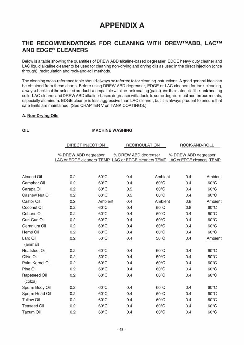
- 48 -
APPENDIX A
THE RECOMMENDATIONS FOR CLEANING WITH DREW™ABD, LAC™AND EDGE® CLEANERS
Below is a table showing the quantities of DREW ABD alkaline-based degreaser, EDGE heavy duty cleaner andLAC liquid alkaline cleaner to be used for cleaning non-drying and drying oils as used in the direct injection (oncethrough), recirculation and rock-and-roll methods.
The cleaning cross-reference table should always be referred to for cleaning instructions. A good general idea canbe obtained from these charts. Before using DREW ABD degreaser, EDGE or LAC cleaners for tank cleaning,always check that the selected product is compatible with the tank coating (paint) and the material of the tank heatingcoils. LAC cleaner and DREW ABD alkaline-based degreaser will attack, to some degree, most nonferrous metals,especially aluminum. EDGE cleaner is less aggressive than LAC cleaner, but it is always prudent to ensure thatsafe limits are maintained. (See CHAPTER V on TANK COATINGS.)
A. Non-Drying Oils
OIL MACHINE WASHING
DIRECT INJECTION RECIRCULATION ROCK-AND-ROLL
% DREW ABD degreaser % DREW ABD degreaser % DREW ABD degreaser LAC or EDGE cleaners TEMP LAC or EDGE cleaners TEMP LAC or EDGE cleaners TEMP
Almond Oil 0.2 50°C 0.4 Ambient 0.4 Ambient
Camphor Oil 0.2 60°C 0.4 60°C 0.4 60°C
Carapa Oil 0.2 60°C 0.5 60°C 0.4 60°C
Cashew Nut Oil 0.2 60°C 0.5 60°C 0.4 60°C
Castor Oil 0.2 Ambient 0.4 Ambient 0.8 Ambient
Coconut Oil 0.2 60°C 0.4 60°C 0.8 60°C
Cohune Oil 0.2 60°C 0.4 60°C 0.4 60°C
Curi-Curi Oil 0.2 60°C 0.4 60°C 0.4 60°C
Geranium Oil 0.2 60°C 0.4 60°C 0.4 60°C
Hemp Oil 0.2 60°C 0.4 60°C 0.4 60°C
Lard Oil 0.2 50°C 0.4 50°C 0.4 Ambient
(animal)
Neatsfoot Oil 0.2 60°C 0.4 60°C 0.4 60°C
Olive Oil 0.2 50°C 0.4 50°C 0.4 50°C
Palm Kernel Oil 0.2 60°C 0.4 60°C 0.4 60°C
Pine Oil 0.2 60°C 0.4 60°C 0.4 60°C
Rapeseed Oil 0.2 60°C 0.4 60°C 0.4 60°C
(colza)
Sperm Body Oil 0.2 60°C 0.4 60°C 0.4 60°C
Sperm Head Oil 0.2 60°C 0.4 60°C 0.4 60°C
Tallow Oil 0.2 60°C 0.4 60°C 0.4 60°C
Teaseed Oil 0.2 60°C 0.4 60°C 0.4 60°C
Tacum Oil 0.2 60°C 0.4 60°C 0.4 60°C

- 49 -
B. Semi-Drying Oils
OIL MACHINE WASHING
DIRECT INJECTION RECIRCULATION ROCK-AND-ROLL
% DREW™ ABD degreaser % DREW ABD degreaser % DREW ABD degreaser EDGE® or LAC™ cleaners TEMP EDGE or LAC cleaners TEMP EDGE or LAC cleaners TEMP
Babassu Oil 0.3 60°C 0.6 50-60°C 0.6 60°CCod Oil 0.3 60°C 0.6 50-60°C 0.6 AmbientCottonseed Oil 0.3 60°C 0.6 50-60°C 0.6 60°CCroton Oil 0.3 60°C 0.6 50-60°C 0.6 60°CHerring Oil 0.3 60°C 0.6 50-60°C 0.6 60°CMaize Oil 0.3 60°C 0.6 50-60°C 0.6 60°CSardine Oil 0.3 60°C 0.6 50-60°C 0.6 AmbientSesame Oil 0.3 60°C 0.6 50-60°C 0.6 60°CShark Oil 0.3 60°C 0.6 50-60°C 0.6 50°CSunflower Seed 0.3 60°C 0.6 50-60°C 0.6 60°C OilWhale Oil 0.3 60°C 0.6 50-60°C 0.6 60°CWheat Oil 0.3 60°C 0.6 50-60°C 0.6 60°C
NOTE: Precleaning Semi-Drying oils with cold water is essential before cleaning commences.
C. Drying Oils
OIL MACHINE WASHING
DIRECT INJECTION RECIRCULATION ROCK-AND-ROLL % DREW ABD degreaser % DREW ABD degreaser % DREW ABD degreaser EDGE or LAC cleaners TEMP EDGE or LAC cleaners TEMP EDGE or LAC cleaners TEMP
Chinawood Oil 0.4 60°C 0.8 60°C 0.8 60°CCandle Nut Oil 0.4 60°C 0.8 60°C 0.8 60°CHempseed Oil 0.4 60°C 0.8 60°C 0.8 40°CLinseed Oil 0.4 60°C 0.8 60°C 0.8 40°CMenhaden Oil 0.4 60°C 0.8 60°C 0.8 40°CMustardseed Oil 0.4 60°C 0.8 60°C 0.8 60°COtticea Oil 0.4 60°C 0.8 60°C 0.8 40°CPerilla Oil 0.4 60°C 0.8 60°C 0.8 AmbientSafflower Oil 0.4 60°C 0.8 60°C 0.8 40°CSoya Bean Oil 0.4 60°C 0.8 60°C 0.8 AmbientTall Oil 0.4 60°C 0.8 60°C 0.8 40°CTung Oil 0.4 60°C 0.8 60°C 0.8 40°CWalnut Oil 0.4 60°C 0.8 60°C 0.8 40°C
NOTE: Precleaning with cold water is essential when removing semi-drying and drying oils and fats. DREW ABDalkkaline-based degreaser, LAC liquid alkaline cleaner and EDGE heavy duty cleaner are outstanding cleaningproducts for removing residues of animal and vegetable oils and fats from cargo tank surfaces. They can be usedto clean away residues left by many types of liquid cargoes and also for removing odors produced by various typesof cargoes. The following general suggestions are for the application of DREW ABD degreaser, LAC cleaner andEDGE cleaner in the most commonly used washing procedures.
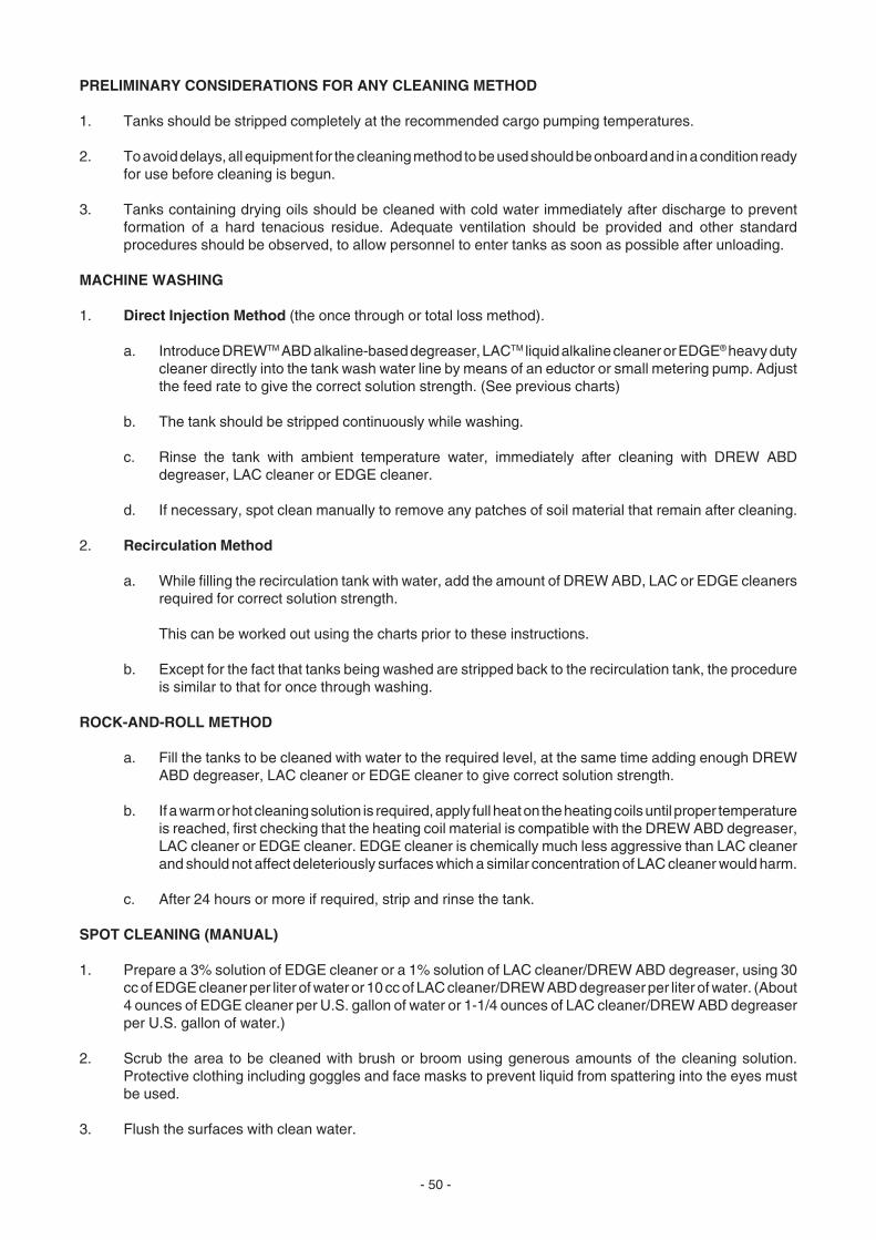
- 50 -
PRELIMINARY CONSIDERATIONS FOR ANY CLEANING METHOD
1. Tanks should be stripped completely at the recommended cargo pumping temperatures.
2. To avoid delays, all equipment for the cleaning method to be used should be onboard and in a condition readyfor use before cleaning is begun.
3. Tanks containing drying oils should be cleaned with cold water immediately after discharge to preventformation of a hard tenacious residue. Adequate ventilation should be provided and other standardprocedures should be observed, to allow personnel to enter tanks as soon as possible after unloading.
MACHINE WASHING
1. Direct Injection Method (the once through or total loss method).
a. Introduce DREWTM ABD alkaline-based degreaser, LACTM liquid alkaline cleaner or EDGE® heavy dutycleaner directly into the tank wash water line by means of an eductor or small metering pump. Adjustthe feed rate to give the correct solution strength. (See previous charts)
b. The tank should be stripped continuously while washing.
c. Rinse the tank with ambient temperature water, immediately after cleaning with DREW ABDdegreaser, LAC cleaner or EDGE cleaner.
d. If necessary, spot clean manually to remove any patches of soil material that remain after cleaning.
2. Recirculation Method
a. While filling the recirculation tank with water, add the amount of DREW ABD, LAC or EDGE cleanersrequired for correct solution strength.
This can be worked out using the charts prior to these instructions.
b. Except for the fact that tanks being washed are stripped back to the recirculation tank, the procedureis similar to that for once through washing.
ROCK-AND-ROLL METHOD
a. Fill the tanks to be cleaned with water to the required level, at the same time adding enough DREWABD degreaser, LAC cleaner or EDGE cleaner to give correct solution strength.
b. If a warm or hot cleaning solution is required, apply full heat on the heating coils until proper temperatureis reached, first checking that the heating coil material is compatible with the DREW ABD degreaser,LAC cleaner or EDGE cleaner. EDGE cleaner is chemically much less aggressive than LAC cleanerand should not affect deleteriously surfaces which a similar concentration of LAC cleaner would harm.
c. After 24 hours or more if required, strip and rinse the tank.
SPOT CLEANING (MANUAL)
1. Prepare a 3% solution of EDGE cleaner or a 1% solution of LAC cleaner/DREW ABD degreaser, using 30cc of EDGE cleaner per liter of water or 10 cc of LAC cleaner/DREW ABD degreaser per liter of water. (About4 ounces of EDGE cleaner per U.S. gallon of water or 1-1/4 ounces of LAC cleaner/DREW ABD degreaserper U.S. gallon of water.)
2. Scrub the area to be cleaned with brush or broom using generous amounts of the cleaning solution.Protective clothing including goggles and face masks to prevent liquid from spattering into the eyes mustbe used.
3. Flush the surfaces with clean water.

- 51 -
It must, of course, be understood that the details of the cleaning methods including temperatures and quantitiesof cleaner may be subject to change due to varying conditions, all of which obviously cannot be discussed in thismanual. Therefore, the above is a guide and not an exact procedure to follow at every occasion.
CAUTION
It should also be noted that many animal and vegetable oils absorb the oxygen from the atmosphere. This isspecifically so after a tank which has been carrying such an oil has been emptied. The residue remaining upon thetank sides can rapidly absorb the oxygen content of the tank rendering it dangerous to enter. At least 18%concentration of oxygen in air is required to support human life.
Certain cargoes such as cashew nut oil, are particularly hazardous and entrance to any tank carrying such a cargoshould never be contemplated. The cargo carrying instructions should always be referred to before entering anytank which has carried any type of liquid.
Following are two graphs (Figures 15 and 16) specifically designed to show the DREW™ ABD degreaser/LAC™liquid alkaline cleaner/EDGE® heavy duty cleaner dosages in gallons and liters per minute against water pressurein pounds per square inch and kilograms per square centimeter for various diameter tank cleaning nozzle tips. Thedosages are specifically for the direct injection cleaning method.
The curves show feed rates in liters/minute to give 0.1% solution. Multiply by the appropriate concentration factorto get feed rates for stronger solutions.
Example: From the graph, locate the point for a 3/8" nozzle tip and water pressure of 10 kg/cm2. Dosage for 0.1%solution is 0.375 liters/minute.
To get 0.2% strength, multiply 0.375 by 2. This gives 0.75 liters per minute.
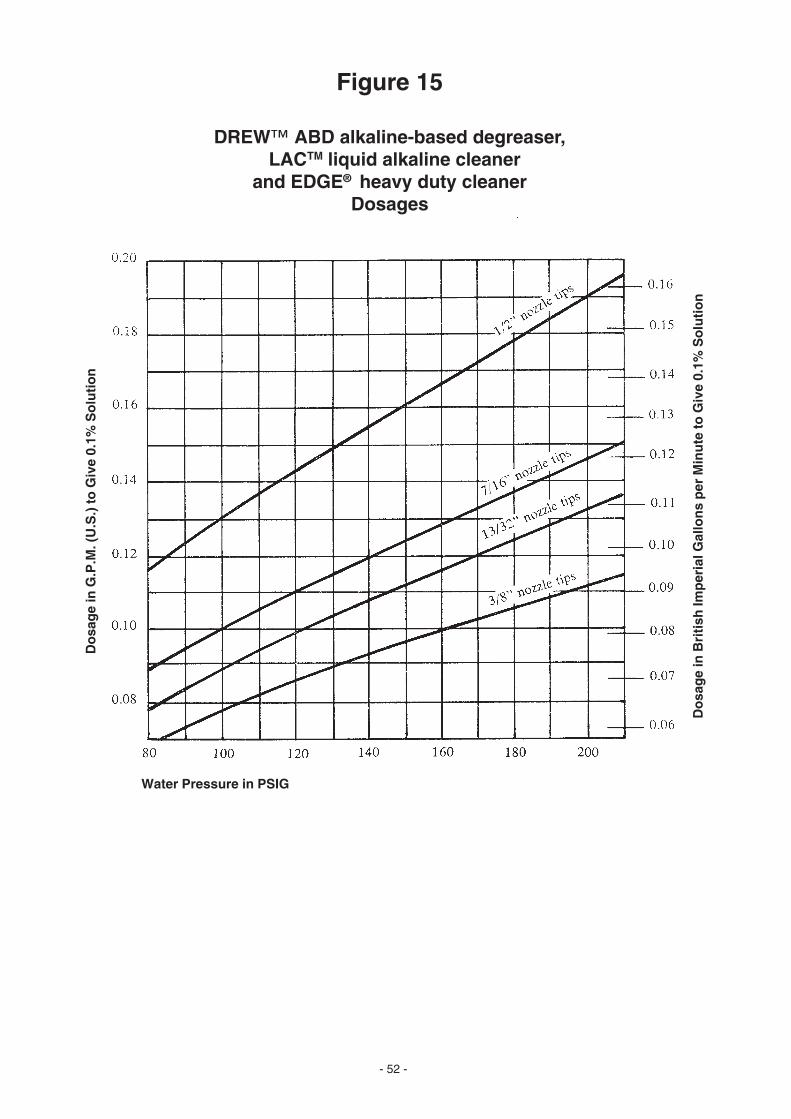
- 52 -
Figure 15
DREW™ ABD alkaline-based degreaser, LACTM liquid alkaline cleaner
and EDGE® heavy duty cleanerDosages
Water Pressure in PSIG
Do
sag
e in
G.P
.M. (
U.S
.) t
o G
ive
0.1%
So
luti
on
Do
sag
e in
Bri
tish
Imp
eria
l Gal
lon
s p
er M
inu
te to
Giv
e 0.
1% S
olu
tio
n

- 53 -
Figure 16
DREW™ ABD alkaline-based degreaser,LACTM liquid alkaline cleaner
and EDGE® heavy duty cleanerDosages
Water Pressure in Kg/Sq. Cm.
Do
sag
e in
Lit
ers/
min
ute
to G
ive
0.1%
So
luti
on

- 54 -
APPENDIX B
SHIP STRUCTURAL DIAGRAMS
Figure 17 - Transverse Section of a Tanker
Figure 18 - Tank Vessel Internal Structure
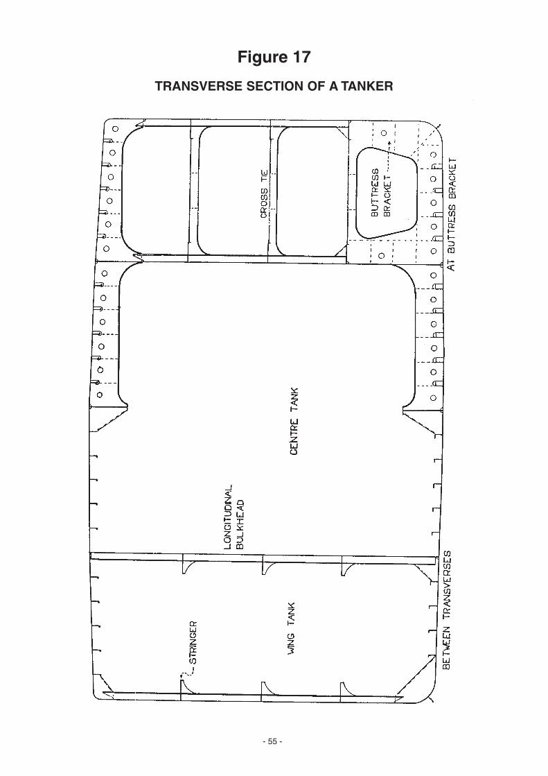
- 55 -
Figure 17
TRANSVERSE SECTION OF A TANKER
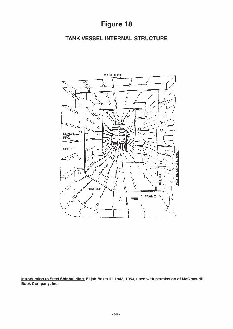
- 56 -
MAIN DECK
LONG'L.FRG.
SHELL
BRACKET
FRAMEWEB
BR
AC
KE
T
Figure 18
TANK VESSEL INTERNAL STRUCTURE
Introduction to Steel Shipbuilding, Elijah Baker III, 1943, 1953, used with permission of McGraw-HillBook Company, Inc.
FL
UT
ED
LO
NG
'L. B
HD
- 57 -
APPENDIX C
A GUIDE TO CRUDE OIL SPECIFICATIONS WORLDWIDE
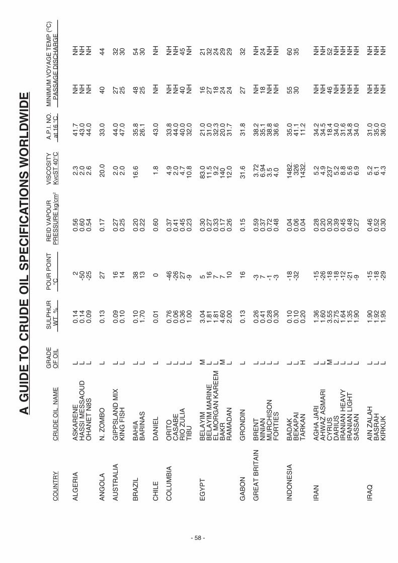
- 58 -
A G
UID
E T
O C
RU
DE
OIL
SP
EC
IFIC
AT
ION
S W
OR
LD
WID
E
GR
AD
ES
ULP
HU
RP
OU
R P
OIN
T R
EID
VA
PO
UR
VIS
CO
SIT
YA
.P.I.
NO
.M
INIM
UM
VO
YA
GE
TE
MP
(OC
)C
OU
NT
RY
CR
UD
E O
IL N
AM
EO
F O
IL W
T %
°C
PR
ES
SU
RE
kg/
cm2
Kvc
ST
40°
C a
t 16
°C
PA
SS
AG
E D
ISC
HA
RG
E
ALG
ER
IAA
SK
AR
EN
E L
0.1
4
2
0.5
6 2
.3 4
1.7
NH
NH
HA
SS
I ME
SS
AO
UD
L 0
.14
-50
0
.60
2.0
43.
0 N
HN
HO
HA
NE
T N
8S L
0.0
9 -
25
0.5
4 2
.6 4
4.0
NH
NH
AN
GO
LAN
. ZO
MB
O L
0.1
3
27
0.1
7 2
0.0
33.
0 4
044
AU
ST
RA
LIA
GIP
PS
LAN
D M
IX L
0.0
9
16
0.2
7 2
.0 4
4.0
27
32K
ING
FIS
H L
0.1
0
14
0.2
5 2
.0 4
7.0
25
30
BR
AZ
ILB
AH
IA L
0.1
0
38
0.2
016
.6 3
5.8
48
54B
AR
INA
S L
1.7
0
13
0.2
2 2
6.1
25
30
CH
ILE
DA
NIE
L L
0.0
1
0
0.6
0 1
.8 4
3.0
NH
NH
CO
LUM
BIA
OR
ITO
L 0
.76
-46
0
.37
4.9
33.
8 N
HN
HC
AS
AB
E L
0.0
6 -
26
0.4
1 2
.0 4
4.0
NH
NH
RIO
ZU
LIA
L 0
.36
27
0
.45
4.7
40.
0 4
045
TIB
U L
1.0
0 -
9
0.2
310
.8 3
2.0
NH
NH
EG
YP
TB
ELA
YIM
M 3
.04
5
0
.30
83.0
21.
0 1
621
BE
LAY
IM M
AR
INE
L 1
.81
16
0
.27
11.5
31.
0 2
732
EL
MO
RG
AN
KA
RE
EM
L 1
.81
7
0
.33
9.2
32.
3 1
824
BA
KR
M 4
.60
7
0
.17
140
20.
0 2
429
RA
MA
DA
N L
2.0
0
10
0.2
612
.0 3
1.7
24
29
GA
BO
NG
RO
ND
IN L
0.1
3
16
0.1
531
.6 3
1.8
27
32
GR
EA
T B
RIT
AIN
BR
EN
T L
0.2
6 -
3
0.5
9 3
.72
38.
2 N
HN
HN
INIA
N L
0.4
1
7
0.3
7 6
.94
35.
1 1
824
MU
RC
HIS
ON
L 0
.28
-1
0
.72
3.5
38.
8 N
HN
HF
OR
TIE
S L
0.3
0 -
3
0.4
8 4
.0 3
6.6
NH
NH
IND
ON
ES
IAB
AD
AK
L 0
.10
-18
0
.04
1482
. 3
5.0
55
60B
EK
AP
AI
L 0
.10
-32
0
.06
326
41.
1 3
035
TA
RK
AN
H 0
.20
0
.04
1432
. 1
1.2
IRA
NA
GH
A J
AR
I L
1.3
6 -
15
0.2
8 5
.2 3
4.2
NH
NH
AH
WA
Z A
SM
AR
I L
1.6
0 -
26
0.2
0 4
.9 3
4.5
NH
NH
CY
RU
S M
3.5
5 -
18
0.3
0 2
37 1
8.4
46
52D
AR
IUS
L 2
.75
-18
0
.39
5.2
34.
0 N
HN
HIR
AN
IAN
HE
AV
Y L
1.6
4 -
12
0.4
5 8
.8 3
1.6
NH
NH
IRA
NIA
N L
IGH
T L
1.3
5 -
21
0.4
8 5
.6 3
4.8
NH
NH
SA
SS
AN
L 1
.90
-9
0
.27
6.9
34.
0 N
HN
H
IRA
QA
IN Z
ALA
H L
1.9
0 -
15
0.4
6 5
.2 3
1.0
NH
NH
BA
SR
AH
L 1
.92
-18
0
.52
6.1
35.
0 N
HN
HK
IRK
UK
L 1
.95
-29
0
.30
4.3
36.
0 N
HN
H
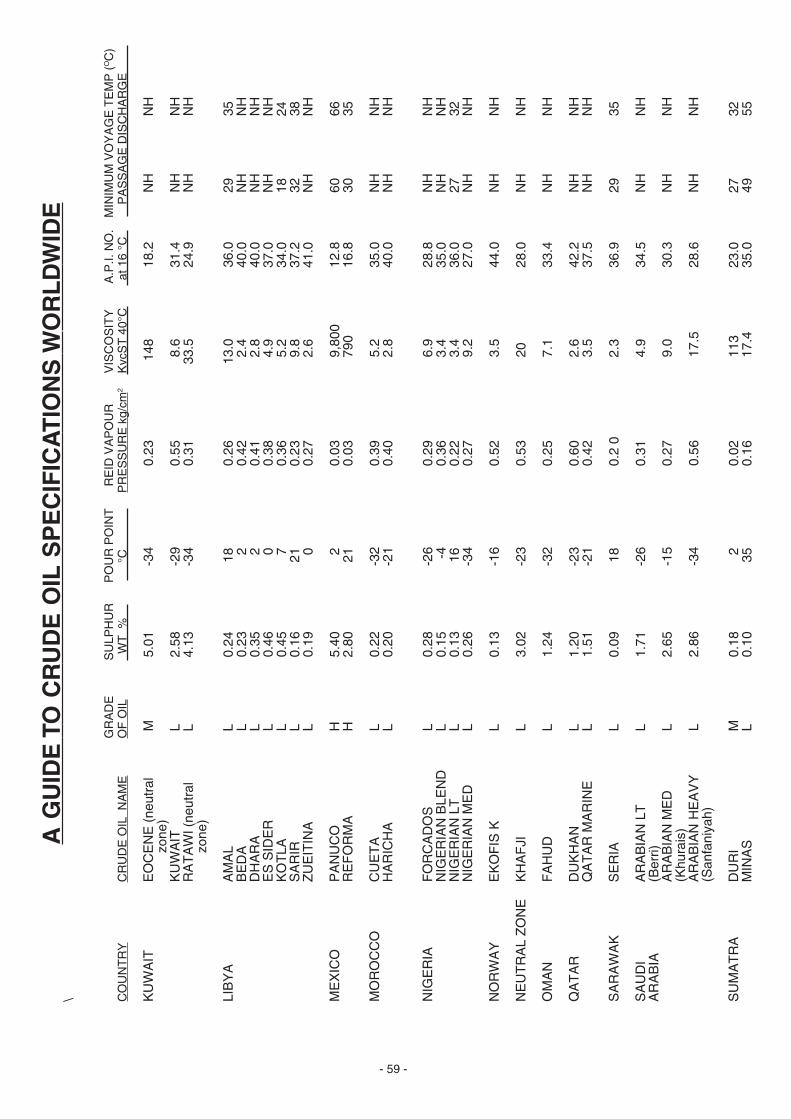
- 59 -
A G
UID
E T
O C
RU
DE
OIL
SP
EC
IFIC
AT
ION
S W
OR
LD
WID
E
\
GR
AD
ES
ULP
HU
RP
OU
R P
OIN
T R
EID
VA
PO
UR
VIS
CO
SIT
YA
.P.I.
NO
.M
INIM
UM
VO
YA
GE
TE
MP
(OC
)C
OU
NT
RY
CR
UD
E O
IL N
AM
EO
F O
IL W
T %
°CP
RE
SS
UR
E k
g/cm
2K
vcS
T 4
0°C
at 1
6 °C
P
AS
SA
GE
DIS
CH
AR
GE
KU
WA
ITE
OC
EN
E (
neut
ral
M 5
.01
-3
4
0.2
3 1
48 1
8.2
NH
NH
zon
e)K
UW
AIT
L 2
.58
-2
9
0.5
5 8
.6 3
1.4
NH
NH
RA
TA
WI (
neut
ral
L 4
.13
-3
4
0.3
133
.5 2
4.9
NH
NH
zon
e)
LIB
YA
AM
AL
L 0
.24
1
8
0.2
613
.0 3
6.0
29
35B
ED
A L
0.2
3
2
0
.42
2.4
40.
0 N
HN
HD
HA
RA
L 0
.35
2
0.4
1 2
.8 4
0.0
NH
NH
ES
SID
ER
L 0
.46
0
0.3
8 4
.9 3
7.0
NH
NH
KO
TLA
L 0
.45
7
0.3
6 5
.2 3
4.0
18
24S
AR
IR L
0.1
6
21
0
.23
9.8
37.
2 3
238
ZU
EIT
INA
L 0
.19
0
0.2
7 2
.6 4
1.0
NH
NH
ME
XIC
OP
AN
UC
O H
5.4
0
2
0
.03
9,8
00 1
2.8
60
66R
EF
OR
MA
H 2
.80
2
1
0.0
3 7
90 1
6.8
30
35
MO
RO
CC
OC
UE
TA
L 0
.22
-3
2
0.3
9 5
.2 3
5.0
NH
NH
HA
RIC
HA
L 0
.20
-2
1
0.4
0 2
.8 4
0.0
NH
NH
NIG
ER
IAF
OR
CA
DO
S L
0.2
8
-26
0
.29
6.9
28.
8 N
HN
HN
IGE
RIA
N B
LEN
D L
0.1
5
-4
0
.36
3.4
35.
0 N
HN
HN
IGE
RIA
N L
T L
0.1
3
16
0
.22
3.4
36.
0 2
732
NIG
ER
IAN
ME
D L
0.2
6
-34
0
.27
9.2
27.
0 N
HN
H
NO
RW
AY
EK
OF
IS K
L 0
.13
-1
6
0.5
2 3
.5 4
4.0
NH
NH
NE
UT
RA
L Z
ON
EK
HA
FJI
L 3
.02
-2
3
0.5
3 2
0 2
8.0
NH
NH
OM
AN
FA
HU
D L
1.2
4
-32
0
.25
7.1
33.
4 N
HN
H
QA
TA
RD
UK
HA
N L
1.2
0
-23
0
.60
2.6
42.
2 N
HN
HQ
AT
AR
MA
RIN
E L
1.5
1
-21
0
.42
3.5
37.
5 N
HN
H
SA
RA
WA
KS
ER
IA L
0.0
9
18
0
.2 0
2.3
36.
9 2
935
SA
UD
IA
RA
BIA
N L
T L
1.7
1
-26
0
.31
4.9
34.
5 N
HN
HA
RA
BIA
(Ber
ri)A
RA
BIA
N M
ED
L 2
.65
-1
5
0.2
7 9
.0 3
0.3
NH
NH
(Khu
rais
)A
RA
BIA
N H
EA
VY
L 2
.86
-3
4
0.5
6 1
7.5
28.
6 N
HN
H(S
anfa
niya
h)
SU
MA
TR
AD
UR
I M
0.1
8
2
0
.02
113
23.
0 2
732
MIN
AS
L 0
.10
3
5
0.1
6 1
7.4
35.
0 4
955
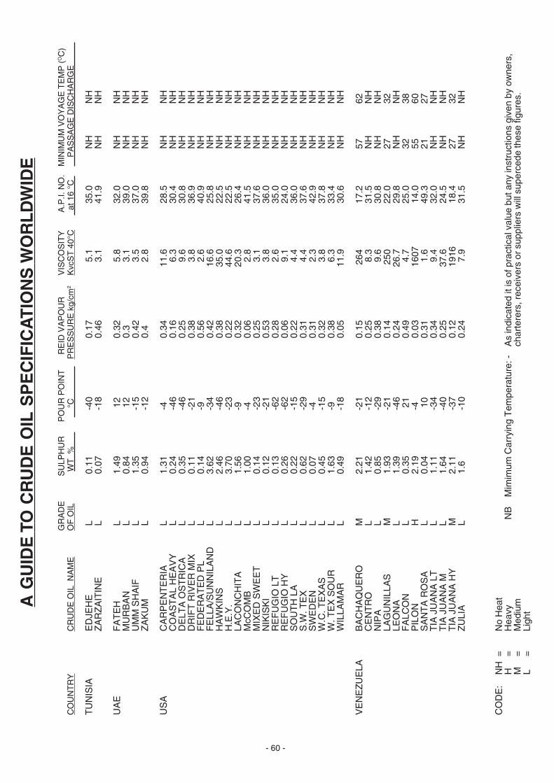
- 60 -
A G
UID
E T
O C
RU
DE
OIL
SP
EC
IFIC
AT
ION
S W
OR
LD
WID
E
GR
AD
ES
ULP
HU
RP
OU
R P
OIN
T R
EID
VA
PO
UR
VIS
CO
SIT
YA
.P.I.
NO
.M
INIM
UM
VO
YA
GE
TE
MP
(OC
)C
OU
NT
RY
CR
UD
E O
IL N
AM
EO
F O
IL W
T %
°CP
RE
SS
UR
E k
g/cm
2K
vcS
T 4
0°C
at 1
6 °C
P
AS
SA
GE
DIS
CH
AR
GE
TU
NIS
IAE
DJE
HE
L 0
.11
-4
0
0.1
7 5
.1 3
5.0
NH
NH
ZA
RZ
AIT
INE
L 0
.07
-1
8
0.4
6 3
.1 4
1.9
NH
NH
UA
EF
AT
EH
L 1
.49
1
2
0.3
2 5
.8 3
2.0
NH
NH
MU
RB
AN
L 0
.84
1
2
0.3
3.1
39.
0 N
HN
HU
MM
SH
AIF
L 1
.35
-1
5
0.4
2 3
.5 3
7.0
NH
NH
ZA
KU
M L
0.9
4
-12
0
.4 2
.8 3
9.8
NH
NH
US
AC
AR
PE
NT
ER
IA L
1.3
1
-4
0.3
411
.6 2
8.5
NH
NH
CO
AS
TA
L H
EA
VY
L 0
.24
-4
6
0.1
6 6
.3 3
0.4
NH
NH
DE
LTA
OS
TR
ICA
L 0
.35
-4
6
0.2
5 9
.6 3
0.8
NH
NH
DR
IFT
RIV
ER
MIX
L 0
.11
-2
1
0.3
8 3
.8 3
6.9
NH
NH
FE
DE
RA
TE
D P
L L
0.1
4
-9
0.5
6 2
.6 4
0.9
NH
NH
FE
LLA
/SU
NN
ILA
ND
L 3
.62
-3
4
0.4
216
.6 2
5.8
NH
NH
HA
WK
INS
L 2
.46
-4
6
0.3
835
.0 2
2.5
NH
NH
H.E
.Y.
L 3
.70
-2
3
0.2
244
.6 2
2.5
NH
NH
LAC
ON
CH
ITA
L 1
.56
-9
0
.32
20.3
26.
4 N
HN
HM
cCO
MB
L 1
.00
-4
0
.06
2.8
41.
5 N
HN
HM
IXE
D S
WE
ET
L 0
.14
-2
3
0.2
5 3
.1 3
7.6
NH
NH
NIK
ISK
I L
0.1
2
-21
0
.53
3.8
36.
0 N
HN
HR
EF
UG
IO L
T L
0.1
3
-62
0
.28
2.6
35.
0 N
HN
HR
EF
UG
IO H
Y L
0.2
6
-62
0
.06
9.1
24.
0 N
HN
HS
OU
TH
LA
L 0
.22
-1
5
0.2
2 4
.4 3
6.0
NH
NH
S.W
. TE
X L
0.6
2
-29
0
.31
4.4
37.
6 N
HN
HS
WE
DE
N L
0.0
7
-4
0.3
1 2
.3 4
2.9
NH
NH
W.C
. TE
XA
S L
0.4
5
-15
0
.32
3.8
37.
8 N
HN
HW
. TE
X S
OU
R L
1.6
3
-9
0.3
8 6
.3 3
3.4
NH
NH
WIL
LAM
AR
L 0
.49
-1
8
0.0
511
.9 3
0.6
NH
NH
VE
NE
ZU
ELA
BA
CH
AQ
UE
RO
M 2
.21
-2
1
0.1
5 2
64 1
7.2
57
62C
EN
TR
O L
1.4
2
-12
0
.25
8.3
31.
5 N
HN
HN
IPA
L 0
.85
-2
9
0.3
8 9
.6 3
0.8
NH
NH
LAG
UN
ILLA
S M
1.9
3
-21
0
.14
250
22.
0 2
732
LEO
NA
L 1
.39
-4
6
0.2
426
.7 2
9.8
NH
NH
FA
LCO
N L
0.3
5
21
0
.49
4.7
25.
0 3
238
PIL
ON
H 2
.19
-4
0
.03
1607
14.
0 5
560
SA
NT
A R
OS
A L
0.0
4
10
0
.31
1.6
49.
3 2
127
TIA
JU
AN
A L
T L
1.1
1
-34
0
.34
9.4
32.
0 N
HN
HT
IA J
UA
NA
M L
1.6
4
-40
0
.25
37.6
24.
5 N
HN
HT
IA J
UA
NA
HY
M 2
.11
-3
7
0.1
219
16 1
8.4
27
32Z
ULI
A L
1.6
-1
0
0.2
4 7
.9 3
1.5
NH
NH
CO
DE
:N
H=
No
Hea
tH
=H
eavy
NB
M
imim
um C
arry
ing
Tem
pera
ture
: -A
s in
dica
ted
it is
of p
ract
ical
val
ue b
ut a
ny in
stru
ctio
ns g
iven
by
owne
rs,
M=
Med
ium
char
tere
rs, r
ecei
vers
or
supp
liers
will
sup
erce
de th
ese
figur
es.
L=
Ligh
t
- 61 -
APPENDIX D
TANK CLEANING PRODUCT CROSS-REFERENCE TABLE ANDCLEANING INSTRUCTION GUIDE
The table which follows is included as a guide to the cleaning of the tanks of a vessel from any one of the 87 listedproducts to any one of the other products included in the table.
It is intended that the recommendations listed in this table be incorporated into the procedures outlined in thefollowing sections of the TANK CLEANING MANUAL:
CHAPTER VII - THE METHODS OF USING CHEMICALS FOR CLEANING PURPOSES
DETERMINING THE NUMBER OF TANK CLEANING MACHINE DROPS FOR EACH CLEANINGJOB, PAGES 28-29
CHAPTER VIII - THE CALCULATION OF CHEMICAL QUANTITIES AND CLEANING TIMES
CLEANING TIME CALCULATION, PAGE 31QUANTITY OF CHEMICAL REQUIRED PAGES 31-33
HOW TO USE THE CROSS-REFERENCE TABLE
The “Tank Cleaning Guide” which precedes the Cross-Reference Table lists the letter codes (A through Y) usedin the table and the cleaning steps recommended for each of these lettered procedures.
Along the left-hand side of the cross-reference table are listed alphabetically 87 products which may be carried.Each has an assigned number. The numbers are repeated along the right-hand side as well.
Along the top and bottom of the table are numbers which refer to these same product names.
To determine the best cleaning procedure to use when going from one product cargo to another, locate the nameand number of the product currently in the tank along the left or right side of the table. Then locate the number ofthe next product to be carried along the top or bottom of the table. Follow along the horizontal row and vertical columnof the two products to the point of intersection. The letter printed at this point refers to the letter of the recommendedcleaning procedure in the “Tank Cleaning Guide”.
For example, if the current cargo is fuel oil and the future cargo is molasses, locate fuel oil (number 30) and molasses(number 49). Since the current cargo is fuel oil, use number 30 along the left or right side of the table. The futurecargo, number 49, should be found along the top or bottom of the table. Look across the page at number 30 anddown the page at 49. The spot where the two rows cross is indicated by the letter “L”. Finally, find cleaning procedure“L” in the Tank Cleaning Guide and follow the recommended cleaning steps.
NOTE: TC#4™ tank cleaner is our recommended tank cleaner. If TC#4 tank cleaner is not available in thequantities required, it may be substituted by using the following other Drew products:
DREWTM TC SEA tank cleaner
DREWTM ABD alkaline-based degreaser, LACTM liquid alkaline cleaner or EDGE® heavy duty cleanershould be used whenever the residues of animal, vegetable or fuel oils and fats are to be cleaned fromtank surfaces. DREW ABD degreaser or LAC cleaner will only be required at times when these sedimentshave been permitted to partially harden on the surfaces and have become sticky and tenacious.
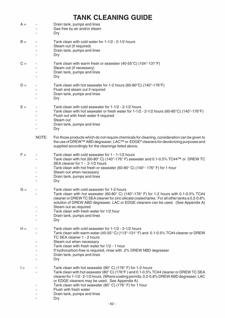
- 62 -
TANK CLEANING GUIDEA = - Drain tank, pumps and lines
- Gas free by air and/or steam- Dry
B = - Tank clean with cold water for 1-1/2 - 2-1/2 hours- Steam out (if required)- Drain tank, pumps and lines- Dry
C = - Tank clean with warm fresh or seawater (40-55°C) (104°-131°F)- Steam out (if necessary)- Drain tank, pumps and lines- Dry
D = - Tank clean with hot seawater for 1-2 hours (60-80°C) (140°-176°F)- Flush and steam out if required- Drain tank, pumps and lines- Dry
E = - Tank clean with cold seawater for 1-1/2 - 2-1/2 hours- Tank clean with hot seawater or fresh water for 1-1/2 - 2-1/2 hours (60-80°C) (140°-176°F)- Flush out with fresh water if required- Steam out- Drain tank, pumps and lines- Dry
NOTE: For those products which do not require chemicals for cleaning, consideration can be given tothe use of DREW™ ABD degreaser, LAC™ or EDGE® cleaners for deodorizing purposes andsupplied accordingly for the cleanings listed above.
F = - Tank clean with cold seawater for 1 - 1-1/2 hours- Tank clean with hot (60-80° C) (140°-176° F) seawater and 0.1-0.5% TC#4™ or DREW TC
SEA cleaner for 1 - 2-1/2 hours - Tank clean with hot fresh or seawater (60-80° C) (140°- 176° F) for 1 hour- Steam out when necessary- Drain tank, pumps and lines- Dry
G = - Tank clean with cold seawater for 1-2 hours- Tank clean with hot seawater (60-80° C) (140°-176° F) for 1-2 hours with 0.1-0.5% TC#4
cleaner or DREW TC SEA cleaner for zinc silicate coated tanks. For all other tanks a 0.2-0.8%solution of DREW ABD degreaser, LAC or EDGE cleaners can be used. (See Appendix A)
- Steam out as required- Tank clean with fresh water for 1/2 hour- Drain tank, pumps and lines- Dry
H = - Tank clean with cold seawater for 1-1/2 - 2-1/2 hours- Tank clean with warm water (45-55° C) (113°-131° F) and 0.1-0.5% TC#4 cleaner or DREW
TC SEA cleaner 1 - 2 hours - Steam out when necessary- Tank clean with fresh water for 1/2 - 1 hour- If hydrocarbon-free is required, rinse with .2% DREW NBD degreaser- Drain tank, pumps and lines- Dry
I = - Tank clean with hot seawater (80° C) (176° F) for 1-2 hours- Tank clean with hot seawater (80° C) (176°F ) and 0.1-0.5% TC#4 cleaner or DREW TC SEA
cleaner for 1-1/2 - 2-1/2 hours. (Where coating permits, 0.2-0.8% DREW ABD degreaser, LACor EDGE cleaners may be used. See Appendix A)
- Tank clean with hot seawater (80° C) (176° F) for 1 hour- Flush with fresh water- Drain tank, pumps and lines- Dry

- 63 -
J = - Tank clean with hot seawater (80°C) (176°F) for 1-2 hours- Tank clean with hot seawater (80°C) (176°F) and 0.1-0.5% TC#4™ cleaner or DREW™ TC
SEA cleaner for 2-1/2 - 3-1/2 hours- Tank clean with hot fresh water for 1-2 hours- Steam out or flush with 0.2% solution of DREW ABD degreaser, LAC™ or EDGE® cleaners
where coating permits. See Appendix A.- Tank clean with hot fresh water and steam out or rinse with hot distilled water- Drain tank, pumps and lines- Dry
K = - Tank wash with hot seawater (80°C) (176°F) for 2-3 hours- Rinse with distilled water- Dry
L = - Tank clean with cold seawater (high wax) for 2 hours- Tank clean with hot (80° C) (176° F) seawater and 0.1-0.5% TC#4 cleaner or DREW TC SEA
cleaner until contamination has been removed- Spot clean as required- Steam out tank if necessary- Tank clean with hot (80° C) (176° F) seawater for 1/2 - 1 hour- Drain tank, pumps and lines- Dry
M = - Tank clean with warm (40-55° C) (104°-131° F) fresh water for 1-2 hours - Drain tank, pumps and lines- Dry
N = - Tank clean with hot (80° C) (176° F) seawater for 1-2 hours- Tank clean with hot (80° C) (176° F) seawater and 0.1-0.5% TC#4 cleaner or DREW TC SEA
cleaner for 1/2 - 1 hour- Steam out- Tank clean with hot fresh water- Drain tank, pumps and lines- Dry
O = - To ease the cleaning process, any tank designated to carry latex should be coated withparaffin wax before loading
- Tank clean with hot water (80°C) (176°F) and 0.1% of TC#4 cleaner or DREW TC SEAcleaner for 1/2 - 1 hour
- Tank clean with hot water (80° C) (176° F) and 0.2-0.8% DREW ABD degreaser, LAC orEDGE cleaners for 2-3 hours. See Appendix A.
- Manually remove from the tank any latex sediments- Tank clean with hot water (80° C) (176° F) and 0.1-0.5% TC#4 or DREW TC SEA cleaner
for 1-2 hours to remove the paraffin wax.- Tank clean with hot seawater for 1-2 hours- Steam out tank- Drain tank, pumps and lines- Dry
P = - Tank clean with hot (80° C) (176° F) seawater for 1-1/2 - 2-1/2 hours- Steam out tank- Tank clean with hot water (80° C) (176° F) and 0.1-0.5% TC#4 cleaner or DREW TC SEA
cleaner for 2 hours- Steam out tank- Tank clean with hot (80° C) (176° F) seawater for 1/2 - 1 hour- Drain tank, pumps and lines- Dry
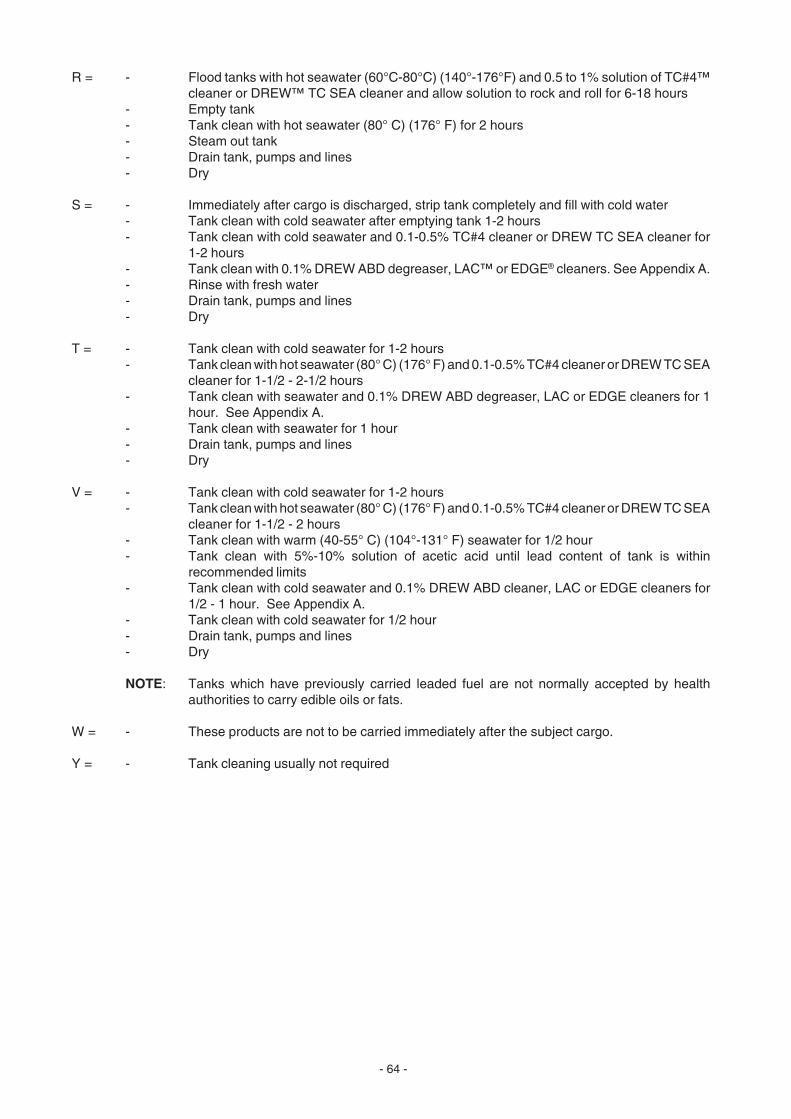
- 64 -
R = - Flood tanks with hot seawater (60°C-80°C) (140°-176°F) and 0.5 to 1% solution of TC#4™cleaner or DREW™ TC SEA cleaner and allow solution to rock and roll for 6-18 hours
- Empty tank- Tank clean with hot seawater (80° C) (176° F) for 2 hours- Steam out tank- Drain tank, pumps and lines- Dry
S = - Immediately after cargo is discharged, strip tank completely and fill with cold water- Tank clean with cold seawater after emptying tank 1-2 hours- Tank clean with cold seawater and 0.1-0.5% TC#4 cleaner or DREW TC SEA cleaner for
1-2 hours- Tank clean with 0.1% DREW ABD degreaser, LAC™ or EDGE® cleaners. See Appendix A.- Rinse with fresh water- Drain tank, pumps and lines- Dry
T = - Tank clean with cold seawater for 1-2 hours- Tank clean with hot seawater (80° C) (176° F) and 0.1-0.5% TC#4 cleaner or DREW TC SEA
cleaner for 1-1/2 - 2-1/2 hours- Tank clean with seawater and 0.1% DREW ABD degreaser, LAC or EDGE cleaners for 1
hour. See Appendix A.- Tank clean with seawater for 1 hour- Drain tank, pumps and lines- Dry
V = - Tank clean with cold seawater for 1-2 hours- Tank clean with hot seawater (80° C) (176° F) and 0.1-0.5% TC#4 cleaner or DREW TC SEA
cleaner for 1-1/2 - 2 hours- Tank clean with warm (40-55° C) (104°-131° F) seawater for 1/2 hour- Tank clean with 5%-10% solution of acetic acid until lead content of tank is within
recommended limits- Tank clean with cold seawater and 0.1% DREW ABD cleaner, LAC or EDGE cleaners for
1/2 - 1 hour. See Appendix A.- Tank clean with cold seawater for 1/2 hour- Drain tank, pumps and lines- Dry
NOTE: Tanks which have previously carried leaded fuel are not normally accepted by healthauthorities to carry edible oils or fats.
W = - These products are not to be carried immediately after the subject cargo.
Y = - Tank cleaning usually not required
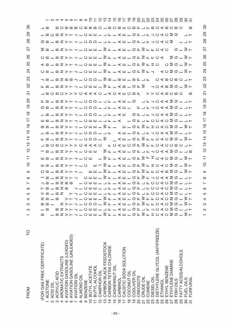
- 65 -
F
RO
M
T
O1
23
45
67
89
1011
1213
1415
1617
1819
2021
2223
2425
2627
2829
30
(F
OR
GA
S F
RE
E C
ER
TIF
ICA
TE
)B
IB
NV
TJ
IC
EE
IL
FI
BE
IG
PL
FJ
CA
CM
GI
L 1
AC
ET
ON
EB
BB
BB
BB
BB
BB
BB
BB
BB
BB
BB
BB
BB
BB
BB
1 2
AC
ID O
ILI
II
II
II
II
II
CI
II
II
II
CI
II
II
II
C
2 3
AC
RY
LIC
AC
IDB
BB
BB
BB
BB
BB
BB
BB
BB
BB
BB
BB
BB
BB
BB
3 4
AR
OM
AT
IC E
XT
RA
CT
SN
NN
NN
NN
NN
NN
CN
NN
NN
NN
CN
NN
NN
NN
NC
4 5
AV
IAT
ION
GA
SO
LIN
E (
LEA
DE
D)
VV
VV
BB
VV
VV
VY
VV
VV
VV
VY
VB
VV
VV
VV
B 5
6 A
VIA
TIO
N G
AS
OLI
NE
(U
NLE
AD
ED
)T
TT
TT
BT
TT
TT
YT
TT
TT
TT
YT
BT
TT
TT
TB
6 7
AV
IAT
ION
OIL
JJ
JJ
JJ
JJ
JJ
JY
JJ
JJ
JJ
JY
JJ
JJ
JJ
JJ
B 7
8 A
LMO
ND
OIL
II
II
II
ΙΙ
ΙΙ
ΙC
II
II
II
IC
II
II
II
II
C 8
9 B
EN
ZE
NE
CC
CC
CC
CC
CC
CA
CC
CC
CC
CA
CC
CC
CC
CC
B 9
10 B
UT
YL
AC
ET
AT
EE
ED
EE
EE
EE
EE
AD
DE
ED
DD
AE
DE
EE
ED
EB
1011
BU
TY
L A
LCO
HO
LE
ED
EE
EE
EE
EE
AD
DE
ED
DD
AE
DE
EE
ED
EB
1112
CA
MP
HO
R O
ILI
II
II
II
II
II
CI
II
II
II
CΙ
ΙΙ
ΙΙ
ΙΙ
ΙC
1213
CA
RB
ON
BLA
CK
FE
ED
ST
OC
KW
LW
WL
LL
WW
WW
WW
LW
LL
LL
LW
WW
WW
WL
LL
1314
CA
RB
ON
TE
TR
A C
HLO
RID
EF
FF
FF
FF
FF
FF
FF
FF
FF
FF
AF
BF
FF
FF
FB
1415
CA
SH
EW
NU
T O
ILI
II
II
II
II
II
IC
II
II
II
CI
II
II
II
IC
1516
CA
RB
INO
LA
AA
AA
AA
AA
AA
AA
AA
AA
AA
AA
BA
AA
AA
AB
1617
CA
US
TIC
SO
DA
SO
LUT
ION
EE
EE
EE
EE
EE
EE
EE
EE
EE
EE
BE
EE
EE
EE
E17
18 C
OC
ON
UT
OIL
II
II
II
II
II
II
CI
II
II
IC
II
II
II
II
C18
19 C
OD
LIV
ER
OIL
GG
GG
GG
GG
GG
GG
GG
GG
GG
GB
GB
GG
GG
GG
B19
20 C
RE
OS
OT
EP
PP
PP
PP
PP
PP
PP
PP
PP
PP
PP
PP
PP
PP
PP
2021
CR
UD
E O
ILW
LW
WL
LL
WW
WW
LW
WL
WL
LL
LW
LW
WW
WL
LL
2122
CU
ME
NE
FF
FF
FF
FF
FF
FF
FF
FF
FF
FF
YF
FF
FF
FF
F22
23 D
IES
EL
OIL
HJ
FF
CC
CJ
FH
HJ
FF
JH
CJ
JJ
YJ
JH
FF
JJ
B23
24 D
IET
HY
LEN
E G
LYC
OL
(AN
TIF
RE
EZ
E)
CC
CC
CC
CC
CC
CC
CC
CC
CC
CC
CC
CC
CC
CC
C24
25 E
TH
AN
OL
AA
AA
AA
AA
AA
AA
AA
AA
AA
AA
AA
AA
AA
AA
A25
26 E
TH
YL
BE
NZ
EN
EC
CC
CC
CC
AB
CC
AC
CA
CC
AA
AB
BB
CC
CC
CB
2627
ET
HY
LEN
E D
IAM
INE
MM
MM
MM
MM
MM
MM
CM
MM
MM
MM
CM
CM
MM
MM
C27
28 F
ISH
OIL
SG
GG
GG
GG
GG
GG
GB
GG
GG
GG
GB
GB
GG
GG
GB
2829
FA
TT
Y A
CID
S/A
LCO
HO
LSI
II
II
II
II
II
IC
ΙΙ
ΙΙ
ΙΙ
ΙC
IC
II
II
IC
2930
FU
EL
OIL
SW
LW
WL
LL
LW
WW
LL
WL
WL
LL
LW
LW
WW
WL
L30
31 F
UR
FU
RA
LT
TT
TT
TT
TT
TT
BT
TT
TT
TT
TB
TT
TT
TT
TT
B31
12
34
56
78
910
1112
1314
1516
1718
1920
2122
2324
2526
2728
2930

- 66 -
F
RO
M
T
O31
3233
3435
3637
3839
4041
4243
4445
4647
4849
5051
5253
5455
5657
(
FO
R G
AS
FR
EE
CE
RT
IFIC
AT
E)
TJ
JC
IG
CC
DF
VJ
IO
GJ
AF
KP
JB
FI
JD
G 1
AC
ET
ON
E B
BB
BB
BB
BB
BB
BB
BB
BB
BB
BB
BB
BB
BB
1 2
AC
ID O
IL I
II
II
II
II
II
II
II
II
II
II
II
II
II
2 3
AC
RY
LIC
AC
ID B
BB
BB
BB
BB
BB
BB
BB
BB
BB
BB
BB
BB
BB
3 4
AR
OM
AT
IC E
XT
RA
CT
S N
NN
NN
NN
NN
NN
NN
NN
NN
NN
NN
NN
NN
NN
4 5
AV
IAT
ION
GA
SO
LIN
E (
LEA
DE
D)
VB
BV
VV
VV
VV
VB
BV
VV
BV
VV
VB
VV
VV
V 5
6 A
VIA
TIO
N G
AS
OLI
NE
(U
NLE
AD
ED
) T
BB
TT
TT
TT
TB
BT
TT
BT
TT
TB
TT
TT
TT
6 7
AV
IAT
ION
OIL
JD
JJ
JJ
JJ
JJ
JJ
JJ
JD
JJ
JJ
DJ
JJ
JJ
J 7
8 A
LMO
ND
OIL
II
II
II
II
II
II
II
II
II
II
II
II
II
I 8
9 B
EN
ZE
NE
CC
CC
CC
CC
CC
CC
CC
CC
CC
CC
CC
CC
CC
C 9
10 B
UT
YL
AC
ET
AT
E E
DD
ED
DE
EE
ED
DE
DD
EE
ED
DE
DE
DE
ED
1011
BU
TY
L A
LCO
HO
L E
DD
ED
DE
EE
ED
DE
DD
EE
ED
DE
DE
DE
ED
1112
CA
MP
HO
R O
IL I
II
II
II
II
II
II
II
II
II
II
II
II
II
1213
CA
RB
ON
BLA
CK
FE
ED
ST
OC
K W
LW
LL
LW
WW
WL
LW
LL
LW
WL
WL
LL
LW
WW
1314
CA
RB
ON
TE
TR
A C
HLO
RID
E F
FF
FF
FF
FF
FF
FF
FF
FF
AF
FF
FF
FF
FF
1415
CA
SH
EW
NU
T O
IL E
II
II
II
II
II
II
II
II
II
II
II
II
II
1516
CA
RB
INO
L A
AA
AA
AA
AA
AA
AA
AA
AA
AA
AA
AA
AA
AA
1617
CA
US
TIC
SO
DA
SO
LUT
ION
EE
EE
EE
EE
EE
EE
EE
EE
EE
EE
EE
EE
EE
E17
18 C
OC
ON
UT
OIL
II
II
II
II
II
II
II
II
II
II
II
II
II
I18
19 C
OD
LIV
ER
OIL
GG
GG
GG
GG
GG
GG
GG
GG
GG
GG
GG
GG
GG
G19
20 C
RE
OS
OT
E P
PP
PP
PP
PP
PP
PP
PP
PP
PP
PP
PP
PP
PP
2021
CR
UD
E O
IL W
LW
LL
LW
WW
WL
LW
LL
LW
WL
WL
LL
LL
WW
2122
CU
ME
NE
FF
FF
FF
FF
FF
FF
FF
FF
FF
FF
FF
FF
FF
F22
23 D
IES
EL
OIL
FB
BH
JJ
FH
HF
CC
JF
JC
HF
JF
CC
FJ
FF
F23
24 D
IET
HY
LEN
E G
LYC
OL
(AN
TIF
RE
EZ
E)
CC
CC
CC
CC
CC
CC
CC
CC
CC
CC
CC
CC
CC
C24
25 E
TH
AN
OL
AA
AA
AA
AA
AA
AA
AA
AA
AA
AA
AA
AA
AA
A25
26 E
TH
YL
BE
NZ
EN
E C
CC
CC
CC
CC
CC
CC
CC
CC
CC
CC
CC
CC
CC
2627
ET
HY
LEN
E D
IAM
INE
MM
MM
MM
MM
MM
MM
MM
MM
MM
MM
MM
MM
MM
M27
28 F
ISH
OIL
S G
GG
GG
GG
GG
GG
GG
GG
GG
GG
GG
GG
GG
GG
2829
FA
TT
Y A
CID
S/A
LCO
HO
LS I
II
II
II
II
II
II
II
II
II
II
II
II
II
2930
FU
EL
OIL
S W
LW
LL
LW
WW
WL
LL
LL
LW
WL
WL
LL
LW
WW
3031
FU
RF
UR
AL
TT
TT
TT
TT
TT
TT
TT
TT
TT
TT
TT
TT
TT
31
3132
3334
3536
3738
3940
4142
4344
4546
4748
4950
5152
5354
5556
57
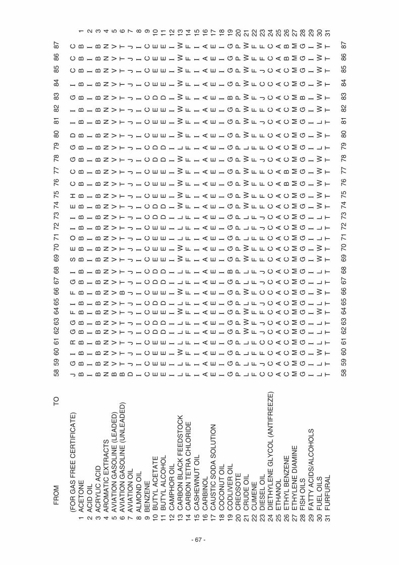
- 67 -
F
RO
M
T
O58
5960
6162
6364
6566
6768
6970
7172
7374
7576
7778
7980
8182
8384
8586
87
(
FO
R G
AS
FR
EE
CE
RT
IFIC
AT
E)
JG
IR
GG
FI
FG
IS
EO
II
EH
CC
GG
DI
IG
IC
CC
1 A
CE
TO
NE
BB
BB
BB
BB
BB
BB
BB
BB
BB
BB
BB
BB
BB
BB
BB
1 2
AC
ID O
ILI
II
II
II
II
II
II
II
II
II
II
II
II
II
II
I 2
3 A
CR
YLI
C A
CID
BB
BB
BB
BB
BB
BB
BB
BB
BB
BB
BB
BB
BB
BB
BB
3 4
AR
OM
AT
IC E
XT
RA
CT
SN
NN
NN
NN
NN
NN
NN
NN
NN
NN
NN
NN
NN
NN
NN
N 4
5 A
VIA
TIO
N G
AS
OLI
NE
(LE
AD
ED
)B
VV
VV
VV
VV
VV
VV
VV
VV
VV
VV
VV
VV
VV
VV
V 5
6 A
VIA
TIO
N G
AS
OLI
NE
(U
NLE
AD
ED
)B
TT
TT
TT
TB
TT
TT
TT
TT
TT
TT
TT
TT
TT
TT
T 6
7 A
VIA
TIO
N O
ILD
JJ
JJ
JJ
JJ
JJ
JJ
JJ
JJ
JJ
JJ
JJ
JJ
JJ
JJ
J 7
8 A
LMO
ND
OIL
II
II
II
II
II
II
II
II
II
II
II
II
II
II
II
8 9
BE
NZ
EN
EC
CC
CC
CC
CC
CC
CC
CC
CC
CC
CC
CC
CC
CC
CC
C 9
10 B
UT
YL
AC
ET
AT
EE
EE
ED
DE
DE
DD
EE
EE
DD
EE
ED
DE
EE
DE
EE
E10
11 B
UT
YL
ALC
OH
OL
EE
EE
DD
ED
ED
DE
EE
ED
DE
EE
DD
EE
ED
EE
EE
1112
CA
MP
HO
R O
ILI
II
II
II
II
II
II
II
II
II
II
II
II
II
II
I12
13 C
AR
BO
N B
LAC
K F
EE
DS
TO
CK
LL
WL
LL
WL
WL
LW
WL
LL
WW
WW
WL
WW
WW
WW
WW
1314
CA
RB
ON
TE
TR
A C
HLO
RID
EF
FF
FF
FF
FF
FF
FF
FF
FF
FF
FF
FF
FF
FF
FF
F14
15 C
AS
HE
WN
UT
OIL
II
II
II
II
II
II
II
II
II
II
II
II
II
II
II
1516
CA
RB
INO
LA
AA
AA
AA
AA
AA
AA
AA
AA
AA
AA
AA
AA
AA
AA
A16
17 C
AU
ST
IC S
OD
A S
OLU
TIO
NE
EE
EE
EE
EE
EE
EE
EE
EE
EE
EE
EE
EE
EE
EE
E17
18 C
OC
ON
UT
OIL
II
II
II
II
II
II
II
II
II
II
II
II
II
II
II
1819
CO
DLI
VE
R O
ILG
GG
GG
GG
GG
GB
GG
GG
GG
GG
GG
GG
GG
BG
GG
G19
20 C
RE
OS
OT
EP
PP
PP
PP
PP
PP
PP
PP
PP
PP
PP
PP
PP
PP
PP
P20
21 C
RU
DE
OIL
LL
LL
WW
WL
WL
LW
WL
LL
WW
WW
WL
WW
WW
WW
WW
2122
CU
ME
NE
FF
FF
FF
FF
FF
FF
FF
FF
FF
FF
FF
FF
FF
FF
FF
2223
DIE
SE
L O
ILC
JF
CJ
JF
JC
JJ
FF
FJ
JF
FF
FJ
FF
JF
JC
JF
F23
24 D
IET
HY
LEN
E G
LYC
OL
(AN
TIF
RE
EZ
E)
CC
CC
CC
CC
CC
CC
CC
CC
CC
CC
CC
CC
CC
CC
CC
2425
ET
HA
NO
LA
AA
AA
AA
AA
AA
AA
AA
AA
AA
AA
AA
AA
AA
AA
A25
26 E
TH
YL
BE
NZ
EN
EC
CC
CC
CC
CC
CC
CC
CC
CC
CB
BC
CC
CC
CC
CB
B26
27 E
TH
YLE
NE
DIA
MIN
EM
MM
MM
MM
MM
MM
MM
MM
MM
MM
MM
MM
MM
MM
MM
M27
28 F
ISH
OIL
SG
GG
GG
GG
GG
GG
GG
GG
GG
GG
GG
GG
GG
BG
GG
G28
29 F
AT
TY
AC
IDS
/ALC
OH
OLS
II
II
II
II
II
II
II
II
II
II
II
II
II
II
II
2930
FU
EL
OIL
SL
LW
LL
LW
LW
LL
WW
LL
LW
WW
WW
LW
LW
WW
WW
W30
31 F
UR
FU
RA
LT
TT
TT
TT
TT
TT
TT
TT
TT
TT
TT
TT
TT
TT
TT
T31
5859
6061
6263
6465
6667
6869
7071
7273
7475
7677
7879
8081
8283
8485
8687
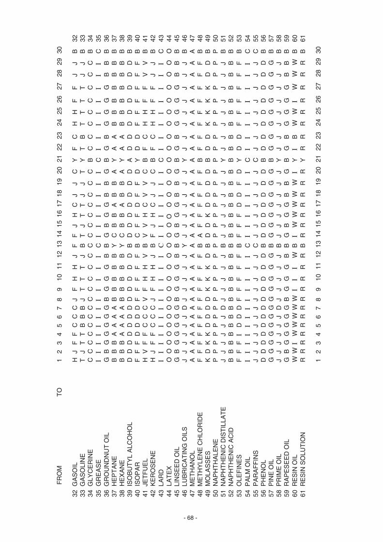
- 68 -
FR
OM
T
O1
23
45
67
89
1011
1213
1415
1617
1819
2021
2223
2425
2627
2829
30
32 G
AS
OIL
HJ
FF
CC
CJ
FH
HJ
FF
JH
CJ
JC
YF
CH
HF
FJ
JB
3233
GA
SO
LIN
ET
JT
TB
BB
JT
TT
JB
TJ
TT
JJ
TY
TB
TT
TT
JJ
B33
34 G
LYC
ER
INE
CC
CC
CC
CC
CC
CC
CC
CC
CC
CC
BC
CC
CC
CC
CB
3435
GR
EA
SE
II
II
II
II
II
II
CI
II
II
II
CI
II
II
II
IC
3536
GR
OU
ND
NU
T O
ILG
BG
GG
GG
BG
GG
BB
GB
GG
BB
GB
GB
GG
GG
BB
B36
37 H
EP
TA
NE
BB
BA
AA
AB
BB
BB
YC
BB
AB
BA
YA
AB
BB
BB
BB
3738
HE
XA
NE
BB
BA
AA
AB
BB
BB
YC
BB
AB
BA
YA
AB
BB
BB
BB
3839
IS
OB
UT
YL
ALC
OH
OL
DD
DD
DD
DD
DD
DD
BD
DD
DD
DD
AD
DD
DD
DD
DB
3940
IS
OP
AR
FF
FD
DD
DF
FF
FF
BC
FF
DF
FD
YD
DF
FF
FF
FB
4041
JE
TF
UE
LH
VF
FC
CC
VF
HH
VB
VV
HC
VV
CB
FC
HH
FF
VV
B41
42 K
ER
OS
EN
EH
JF
FC
CC
JF
HH
JB
FJ
HC
JJ
CB
FC
HH
FF
JJ
B42
43 L
AR
DI
II
II
II
II
II
IC
II
II
II
IC
II
II
II
II
C43
44 L
AT
EX
OO
OO
OO
OO
OO
OO
OO
O O
OO
OO
OO
OO
OO
OO
OO
4445
LIN
SE
ED
OIL
GB
GG
GG
GB
GG
GB
BG
BG
GB
BG
BG
BG
GG
GB
BB
4546
LU
BR
ICA
TIN
G O
ILS
JJ
JJ
JJ
DJ
JJ
JJ
YJ
JJ
JJ
JJ
YJ
JJ
JJ
JJ
JB
4647
ME
TH
AN
OL
AA
AA
AA
AA
AA
AA
AA
AA
AA
AA
AA
AA
AA
AA
AA
4748
ME
TH
YLE
NE
CH
LOR
IDE
FF
FF
FF
FF
FF
FF
BA
FF
FF
FF
BF
FF
FF
FF
FB
4849
MO
LAS
SE
SK
DK
KD
DD
DK
KK
DB
DD
KD
DD
DB
DD
KK
KK
DD
B49
50 N
AP
HT
HA
LEN
EP
PP
PP
PP
PP
PP
PP
PP
PP
PP
PP
PP
PP
PP
PP
P50
51 N
AP
HT
HE
NIC
DIS
TIL
LAT
EJ
JJ
JJ
JD
JJ
JJ
JB
JJ
JJ
JJ
JY
JJ
JJ
JJ
JJ
B51
52 N
AP
HT
HE
NIC
AC
IDB
BB
BB
BB
BB
BB
BB
BB
BB
BB
BB
BB
BB
BB
BB
B52
53 O
LEF
INE
SF
FF
ID
DD
FF
FF
FB
FF
FD
DF
DY
DD
FF
FF
FF
B53
54 P
ALM
OIL
II
II
II
II
II
II
CI
II
II
II
CI
II
II
II
IC
5455
PA
RA
FF
INS
JJ
JJ
JJ
JJ
JJ
JJ
CJ
JJ
JJ
JJ
CJ
JJ
JJ
JJ
JC
5556
PH
EN
OL
DD
DD
DD
DD
DD
DD
BD
DD
DD
DD
BD
DD
DD
DD
DB
5657
PIN
E O
ILG
GG
GG
GG
GG
GG
GB
GG
GG
GG
GB
GG
GG
GG
GG
B57
58 P
RIM
E O
ILJ
JJ
JJ
JD
JJ
JJ
JB
JJ
JJ
JJ
JY
JJ
JJ
JJ
JJ
B58
59 R
AP
ES
EE
D O
ILG
BG
GG
GG
BG
GG
BB
GB
GG
BB
GB
GB
GG
GG
BB
B59
60 R
ES
IN O
ILW
WI
WW
WW
WI
II
WB
IW
WW
WW
IY
IB
WW
IW
WW
B60
61 R
ES
IN S
OLU
TIO
NR
RR
RR
RR
RR
RR
RB
RR
RR
RR
RY
RR
RR
RR
RR
B61
12
34
56
78
910
1112
1314
1516
1718
1920
2122
2324
2526
2728
2930
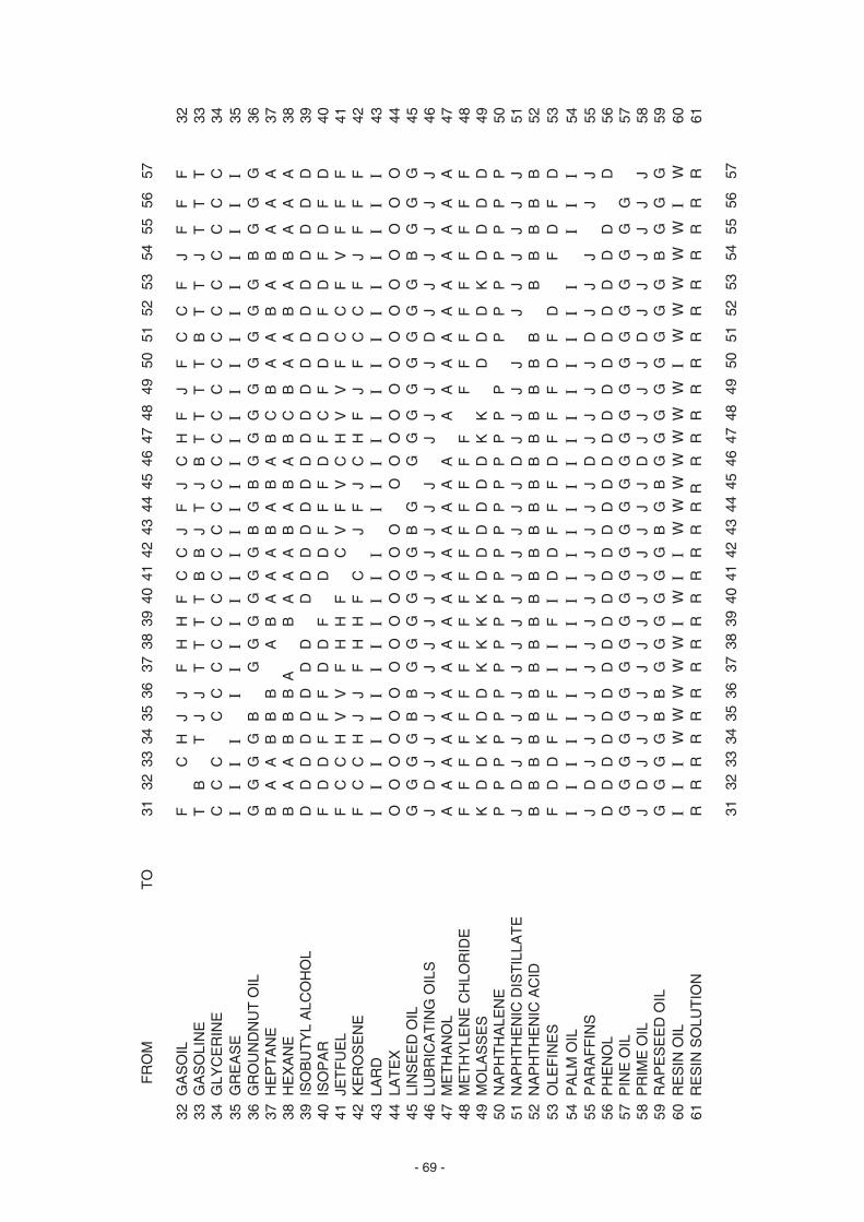
- 69 -
F
RO
M
T
O31
3233
3435
3637
3839
4041
4243
4445
4647
4849
5051
5253
5455
5657
32 G
AS
OIL
FC
HJ
JF
HH
FC
CJ
FJ
CH
FJ
FC
CF
JF
FF
3233
GA
SO
LIN
ET
BT
JJ
TT
TT
BB
JT
JB
TT
TT
BT
TJ
TT
T33
34 G
LYC
ER
INE
CC
CC
CC
CC
CC
CC
CC
CC
CC
CC
CC
CC
CC
3435
GR
EA
SE
II
II
II
II
II
II
II
II
II
II
II
II
II
3536
GR
OU
ND
NU
T O
ILG
GG
GB
GG
GG
GG
BG
BG
GG
GG
GG
GB
GG
G36
37 H
EP
TA
NE
BA
AB
BB
AB
AA
AB
AB
AB
CB
AA
BA
BA
AA
3738
HE
XA
NE
BA
AB
BB
AB
AA
AB
AB
AB
CB
AA
BA
BA
AA
3839
IS
OB
UT
YL
ALC
OH
OL
DD
DD
DD
DD
DD
DD
DD
DD
DD
DD
DD
DD
DD
3940
IS
OP
AR
FD
DF
FF
DD
FD
DF
FF
DF
CF
DD
FD
FD
FD
4041
JE
TF
UE
LF
CC
HV
VF
HH
FC
VF
VC
HV
VF
CC
FV
FF
F41
42 K
ER
OS
EN
EF
CC
HJ
JF
HH
FC
JF
JC
HF
JF
CC
FJ
FF
F42
43 L
AR
DI
II
II
II
II
II
II
II
II
II
II
II
II
I43
44 L
AT
EX
OO
OO
OO
OO
OO
OO
OO
OO
OO
OO
OO
OO
OO
4445
LIN
SE
ED
OIL
GG
GG
BB
GG
GG
GG
BG
GG
GG
GG
GG
BG
GG
4546
LU
BR
ICA
TIN
G O
ILS
JD
JJ
JJ
JJ
JJ
JJ
JJ
JJ
JJ
JD
JJ
JJ
JJ
4647
ME
TH
AN
OL
AA
AA
AA
AA
AA
AA
AA
AA
AA
AA
AA
AA
AA
4748
ME
TH
YLE
NE
CH
LOR
IDE
FF
FF
FF
FF
FF
FF
FF
FF
FF
FF
FF
FF
FF
4849
MO
LAS
SE
SK
DD
KD
DK
KK
KD
DD
DD
DK
KD
DD
KD
DD
D49
50 N
AP
HT
HA
LEN
EP
PP
PP
PP
PP
PP
PP
PP
PP
PP
PP
PP
PP
P50
51 N
AP
HT
HE
NIC
DIS
TIL
LAT
EJ
DJ
JJ
JJ
JJ
JJ
JJ
JJ
DJ
JJ
JJ
JJ
JJ
J51
52 N
AP
HT
HE
NIC
AC
IDB
BB
BB
BB
BB
BB
BB
BB
BB
BB
BB
BB
BB
B52
53 O
LEF
INE
SF
DD
FF
FI
IF
ID
DF
FF
DF
FF
DF
DF
DF
D53
54 P
ALM
OIL
II
II
II
II
II
II
II
II
II
II
II
II
II
5455
PA
RA
FF
INS
JD
JJ
JJ
JJ
JJ
JJ
JJ
JD
JJ
JJ
DJ
JJ
JJ
5556
PH
EN
OL
DD
DD
DD
DD
DD
DD
DD
DD
DD
DD
DD
DD
DD
5657
PIN
E O
ILG
GG
GG
GG
GG
GG
GG
GG
GG
GG
GG
GG
GG
G57
58 P
RIM
E O
ILJ
DJ
JJ
JJ
JJ
JJ
JJ
JJ
DJ
JJ
JD
JJ
JJ
JJ
5859
RA
PE
SE
ED
OIL
GG
GG
BB
GG
GG
GG
BG
BG
GG
GG
GG
GB
GG
G59
60 R
ES
IN O
ILI
II
WW
WW
WI
WI
IW
WW
WW
WW
IW
WW
WW
IW
6061
RE
SIN
SO
LUT
ION
RR
RR
RR
RR
RR
RR
RR
RR
RR
RR
RR
RR
RR
R61
3132
3334
3536
3738
3940
4142
4344
4546
4748
4950
5152
5354
5556
57

- 70 -
FR
OM
T
O58
5960
6162
6364
6566
6768
6970
7172
7374
7576
7778
7980
8182
8384
8586
87
32 G
AS
OIL
CJ
FC
JJ
FJ
CJ
JF
FF
JJ
FF
FF
JF
FJ
FJ
CJ
FF
3233
GA
SO
LIN
EB
JT
TJ
JT
JB
JJ
TT
TJ
JT
TT
TJ
TT
JT
JB
TT
T33
34 G
LYC
ER
INE
CC
CC
CC
CC
CC
CC
CC
CC
CC
CC
CC
CC
CC
CC
CC
3435
GR
EA
SE
II
II
II
II
II
II
II
II
II
II
II
II
II
II
II
3536
GR
OU
ND
NU
T O
ILG
BG
GB
BG
BG
BB
GG
GB
BG
GG
GB
GG
BG
BG
GG
G36
37 H
EP
TA
NE
AB
AA
BB
AB
AB
BB
BA
BB
BA
BB
BA
BB
BB
AB
BB
3738
HE
XA
NE
AB
AA
BB
AB
AB
BB
BA
BB
BA
BB
BA
BB
BB
AB
BB
3839
IS
OB
UT
YL
ALC
OH
OL
DD
DD
DD
DD
DD
DD
DD
DD
DD
DD
DD
DD
DD
DD
DD
3940
IS
OP
AR
DF
DD
FF
DF
DF
FF
FF
FF
FF
FF
FD
FF
FF
DF
FF
4041
JE
TF
UE
LC
VF
CV
VF
VC
VV
FF
FV
VF
FF
FV
FF
VF
VC
VF
F41
42 K
ER
OS
EN
EC
JF
CJ
JF
JC
JJ
FF
FJ
JF
FF
FJ
FF
JF
JC
JF
F42
43 L
AR
DI
II
II
II
II
II
II
II
II
II
II
II
II
II
II
I43
44 L
AT
EX
OO
OO
OO
OO
OO
OO
OO
OO
OO
OO
OO
OO
OO
OO
OO
4445
LIN
SE
ED
OIL
GG
GG
BB
GB
GB
BG
GG
BB
GG
GG
BG
GB
GB
GG
GG
4546
LU
BR
ICA
TIN
G O
ILS
DJ
JJ
JJ
JJ
JJ
JJ
JJ
JJ
JJ
JJ
JJ
JJ
JJ
JJ
JJ
4647
ME
TH
AN
OL
AA
AA
AA
AA
AA
AA
AA
AA
AA
AA
AA
AA
AA
AA
AA
4748
ME
TH
YLE
NE
CH
LOR
IDE
FF
FF
FF
FF
FF
FF
FF
FF
FF
FF
FF
FF
FF
FF
FF
4849
MO
LAS
SE
SD
DD
KD
DK
DD
DD
KD
DD
DD
KK
KK
DK
DK
DD
KK
K49
50 N
AP
HT
HA
LEN
EP
PP
PP
PP
PP
PP
PP
PP
PP
PP
PP
PP
PP
PP
PP
P50
51 N
AP
HT
HE
NIC
DIS
TIL
LAT
ED
JJ
JJ
JJ
JJ
JJ
JJ
JJ
JJ
JJ
JJ
JJ
JJ
JJ
JJ
J51
52 N
AP
HT
HE
NIC
AC
IDB
BB
BB
BB
BB
BB
BB
BB
BB
BB
BB
BB
BB
BB
BB
B52
53 O
LEF
INE
SD
FD
DF
FI
FD
FF
FF
FF
FF
FF
FF
DF
FF
FI
FF
F53
54 P
ALM
OIL
II
II
II
II
II
II
II
II
II
II
II
II
II
II
II
5455
PA
RA
FF
INS
DJ
JJ
JJ
JJ
JJ
JJ
JJ
JJ
JJ
JJ
JJ
JJ
JJ
JJ
JJ
5556
PH
EN
OL
DD
DD
DD
DD
DD
DD
DD
DD
DD
DD
DD
DD
DD
DD
DD
5657
PIN
E O
ILG
GG
GG
GG
GG
GG
GG
GG
GG
GG
GG
GG
GG
GG
GG
G57
58 P
RIM
E O
ILJ
JJ
JJ
JJ
JJ
JJ
JJ
JJ
JJ
JJ
JJ
JJ
JJ
JJ
JJ
5859
RA
PE
SE
ED
OIL
GG
GB
BG
BG
BB
GG
GB
BG
GG
GB
GG
BG
BG
GG
G59
60 R
ES
IN O
IL W
WI
WW
WW
IW
WI
WW
WW
WW
II
WW
WW
WW
WW
II
6061
RE
SIN
SO
LUT
ION
R R
RR
RR
RR
RR
RR
RR
RR
RR
RR
RR
RR
RR
RR
R61
5859
6061
6263
6465
6667
6869
7071
7273
7475
7677
7879
8081
8283
8485
8687

- 71 -
FR
OM
T
O1
23
45
67
89
1011
1213
1415
1617
1819
2021
2223
2425
2627
2829
30
62 S
AF
FLO
WE
R O
ILG
BG
GG
GG
BG
GG
BB
GB
GG
BB
GB
GB
GG
GG
BB
B62
63 S
ES
AM
E O
ILG
BG
GG
GG
GG
GG
BB
GB
GG
BB
GB
GB
GG
GG
BB
B63
64 S
HE
LLS
OL
FF
FD
DD
DF
FF
FF
BF
FF
DF
DF
YD
DF
FF
FF
FB
6465
SO
AP
ST
OC
KI
II
II
II
II
II
IC
II
II
II
IC
II
II
II
II
C65
66 S
OLV
EN
T N
AP
TH
AF
FF
DD
DD
FF
FF
FB
FF
FD
FF
DY
DD
FF
FF
FF
B66
67 S
OY
BE
AN
GG
GG
GG
GG
GG
GG
BG
GG
GG
GG
BG
BG
GG
GG
GB
6768
SP
ER
M O
ILI
II
II
II
II
II
IC
II
II
IC
IC
II
II
II
CI
C68
69 S
TY
RE
NE
MO
NO
ME
RS
SS
SS
SS
SS
SS
SB
SS
SS
SS
SB
SS
SS
SS
SS
B69
70 S
UR
FO
NIC
EE
EE
EE
EE
EE
EE
BE
EE
EE
EE
BE
EE
EE
EE
EB
7071
SY
NT
HE
TIC
LA
TE
XO
OO
OO
OO
OO
OO
OO
OO
OO
OO
OO
OO
OO
OO
OO
O71
72 T
ALL
OIL
II
II
II
II
II
II
CI
II
II
CI
CI
II
II
IC
IC
7273
TA
LLO
WI
II
II
II
II
II
IC
II
II
IC
IC
II
II
II
CI
C73
74 T
EE
PO
LE
EE
EE
EE
EE
EE
EB
EE
EE
EE
EB
EE
EE
EE
EE
B74
75 T
EX
AN
OL
HH
HH
HH
HH
HH
HH
BH
HH
HH
HH
BH
HH
HH
HH
HB
7576
TO
LUE
NE
CC
CC
CC
CC
BC
CC
CC
CC
CC
CC
BB
CC
CB
CC
CB
7677
TO
LUO
LC
CC
CC
CC
CB
CC
CC
CC
CC
CC
CB
BC
CC
BC
CC
B77
78 T
UN
G O
ILG
GG
GG
GG
GG
GG
GB
GG
GG
GG
GB
GB
GG
GG
GG
B78
79 T
UR
PE
NT
INE
GG
GG
GG
GG
GG
GG
BG
GG
GG
GG
BG
BG
GG
GG
GB
7980
VE
RS
EN
ED
DD
DD
DD
DD
DD
DB
DD
DD
DD
DB
DD
DD
DD
DD
B80
81 V
EG
ET
AB
LE O
ILS
II
II
II
II
II
II
CI
II
II
CI
CI
II
II
IC
IC
8182
VO
RA
NO
LI
II
II
II
II
II
IC
II
II
II
IC
II
II
II
CI
I82
83 W
HA
LE O
ILG
GG
GG
GG
GG
GG
GB
GG
GG
GG
GB
GG
GG
GG
GG
B83
84 W
HIT
E S
PIR
ITI
FF
FE
EE
II
FF
IB
II
FE
II
EB
EE
FF
IF
II
B84
85 W
INE
CC
CC
CC
CC
CC
CC
CC
CC
CC
CY
CB
CC
CC
CC
B85
86 X
YLE
NE
CC
CC
CC
CC
BC
CC
CC
CC
CC
CB
YC
BC
CC
CC
CB
8687
XY
LOL
CC
CC
CC
CC
BC
CC
CC
CC
CC
CB
YC
BC
CC
CC
CB
87
12
34
56
78
910
1112
1314
1516
1718
1920
2122
2324
2526
2728
2930
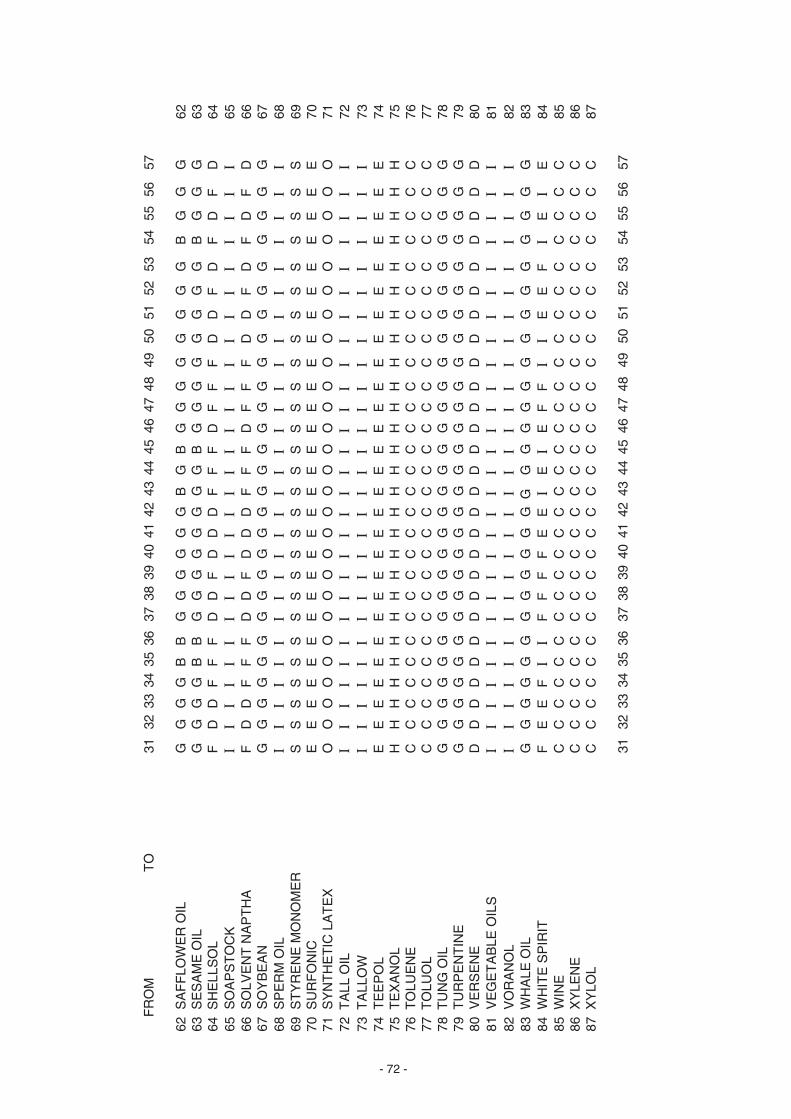
- 72 -
F
RO
M
TO
3132
3334
3536
3738
3940
4142
4344
4546
4748
4950
5152
5354
5556
57
62 S
AF
FLO
WE
R O
ILG
GG
GB
BG
GG
GG
GB
GB
GG
GG
GG
GG
BG
GG
6263
SE
SA
ME
OIL
GG
GG
BB
GG
GG
GG
GG
BG
GG
GG
GG
GB
GG
G63
64 S
HE
LLS
OL
FD
DF
FF
DD
FD
DD
FF
FD
FF
FD
DF
DF
DF
D64
65 S
OA
PS
TO
CK
II
II
II
II
II
II
II
II
II
II
II
II
II
I65
66 S
OLV
EN
T N
AP
TH
AF
DD
FF
FD
DF
DD
DF
FF
DF
FF
DD
FD
FD
FD
6667
SO
YB
EA
NG
GG
GG
GG
GG
GG
GG
GG
GG
GG
GG
GG
GG
GG
6768
SP
ER
M O
ILI
II
II
II
II
II
II
II
II
II
II
II
II
II
6869
ST
YR
EN
E M
ON
OM
ER
SS
SS
SS
SS
SS
SS
SS
SS
SS
SS
SS
SS
SS
S69
70 S
UR
FO
NIC
EE
EE
EE
EE
EE
EE
EE
EE
EE
EE
EE
EE
EE
E70
71 S
YN
TH
ET
IC L
AT
EX
OO
OO
OO
OO
OO
OO
OO
OO
OO
OO
OO
OO
OO
O71
72 T
ALL
OIL
II
II
II
II
II
II
II
II
II
II
II
II
II
I72
73 T
ALL
OW
II
II
II
II
II
II
II
II
II
II
II
II
II
I73
74 T
EE
PO
LE
EE
EE
EE
EE
EE
EE
EE
EE
EE
EE
EE
EE
EE
7475
TE
XA
NO
LH
HH
HH
HH
HH
HH
HH
HH
HH
HH
HH
HH
HH
HH
7576
TO
LUE
NE
CC
CC
CC
CC
CC
CC
CC
CC
CC
CC
CC
CC
CC
C76
77 T
OLU
OL
CC
CC
CC
CC
CC
CC
CC
CC
CC
CC
CC
CC
CC
C77
78 T
UN
G O
ILG
GG
GG
GG
GG
GG
GG
GG
GG
GG
GG
GG
GG
GG
7879
TU
RP
EN
TIN
EG
GG
GG
GG
GG
GG
GG
GG
GG
GG
GG
GG
GG
GG
7980
VE
RS
EN
ED
DD
DD
DD
DD
DD
DD
DD
DD
DD
DD
DD
DD
DD
8081
VE
GE
TA
BLE
OIL
SI
II
II
II
II
II
II
II
II
II
II
II
II
II
8182
VO
RA
NO
LI
II
II
II
II
II
II
II
II
II
II
II
II
II
8283
WH
ALE
OIL
GG
GG
GG
GG
GG
GG
GG
GG
GG
GG
GG
GG
GG
G83
84 W
HIT
E S
PIR
ITF
EE
FI
IF
FF
FE
EI
EI
EF
FI
IE
EF
IE
IE
8485
WIN
EC
CC
CC
CC
CC
CC
CC
CC
CC
CC
CC
CC
CC
CC
8586
XY
LEN
EC
CC
CC
CC
CC
CC
CC
CC
CC
CC
CC
CC
CC
CC
8687
XY
LOL
CC
CC
CC
CC
CC
CC
CC
CC
CC
CC
CC
CC
CC
C87
3132
3334
3536
3738
3940
4142
4344
4546
4748
4950
5152
5354
5556
57
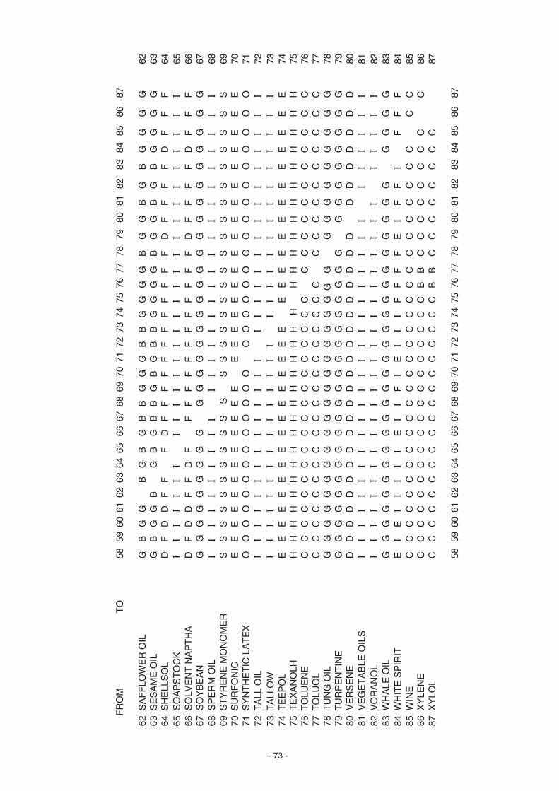
- 73 -
F
RO
M
TO
5859
6061
6263
6465
6667
6869
7071
7273
7475
7677
7879
8081
8283
8485
8687
62 S
AF
FLO
WE
R O
ILG
BG
GB
GB
GB
BG
GG
BB
GG
GG
BG
GB
GB
GG
GG
6263
SE
SA
ME
OIL
GB
GG
BG
BG
BB
GB
GB
BG
GG
GB
GG
BG
BG
GG
G63
64 S
HE
LLS
OL
DF
DD
FF
FD
FF
FF
FF
FF
FF
FF
DF
FF
FD
FF
F64
65 S
OA
PS
TO
CK
II
II
II
II
II
II
II
II
II
II
II
II
II
II
I65
66 S
OLV
EN
T N
AP
TH
AD
FD
DF
FD
FF
FF
FF
FF
FF
FF
FD
FF
FF
DF
FF
6667
SO
YB
EA
NG
GG
GG
GG
GG
GG
GG
GG
GG
GG
GG
GG
GG
GG
GG
6768
SP
ER
M O
ILI
II
II
II
II
II
II
II
II
II
II
II
II
II
II
6869
ST
YR
EN
E M
ON
OM
ER
SS
SS
SS
SS
SS
SS
SS
SS
SS
SS
SS
SS
SS
SS
S69
70 S
UR
FO
NIC
EE
EE
EE
EE
EE
EE
EE
EE
EE
EE
EE
EE
EE
EE
E70
71 S
YN
TH
ET
IC L
AT
EX
OO
OO
OO
OO
OO
OO
OO
OO
OO
OO
OO
OO
OO
OO
O71
72 T
ALL
OIL
II
II
II
II
II
II
II
II
II
II
II
II
II
II
I72
73 T
ALL
OW
II
II
II
II
II
II
II
II
II
II
II
II
II
II
I73
74 T
EE
PO
LE
EE
EE
EE
EE
EE
EE
EE
EE
EE
EE
EE
EE
EE
EE
7475
TE
XA
NO
LHH
HH
HH
HH
HH
HH
HH
HH
H H
HH
HH
HH
HH
HH
HH
7576
TO
LUE
NE
CC
CC
CC
CC
CC
CC
CC
CC
CC
CC
CC
CC
CC
CC
C76
77 T
OLU
OL
CC
CC
CC
CC
CC
CC
CC
CC
CC
CC
CC
CC
CC
CC
C77
78 T
UN
G O
ILG
GG
GG
GG
GG
GG
GG
GG
GG
G G
GG
GG
GG
GG
GG
7879
TU
RP
EN
TIN
EG
GG
GG
GG
GG
GG
GG
GG
GG
GG
GG
GG
GG
GG
GG
7980
VE
RS
EN
ED
DD
DD
DD
DD
DD
DD
DD
DD
DD
DD
DD
DD
DD
DD
8081
VE
GE
TA
BLE
OIL
SI
II
II
II
II
II
II
II
II
II
II
II
II
II
II
8182
VO
RA
NO
LI
II
II
II
II
II
II
II
II
II
II
II
II
II
II
8283
WH
ALE
OIL
GG
GG
GG
GG
GG
GG
GG
GG
GG
GG
GG
GG
GG
GG
G83
84 W
HIT
E S
PIR
ITE
IE
II
II
IE
II
FI
EI
II
FF
FF
EI
FF
IF
FF
8485
WIN
EC
CC
CC
CC
CC
CC
CC
CC
CC
CC
CC
CC
CC
CC
CC
8586
XY
LEN
EC
CC
CC
CC
CC
CC
CC
CC
CC
CB
BC
CC
CC
CC
CC
8687
XY
LOL
CC
CC
CC
CC
CC
CC
CC
CC
CC
BB
CC
CC
CC
CC
87
5859
6061
6263
6465
6667
6869
7071
7273
7475
7677
7879
8081
8283
8485
8687

- 74 -
APPENDIX E
SQUARE ROOT TABLE
NUMBER SQUARE ROOT(Deadweight tonnage - dwt) ( ) (Approximate)
1,000 32
2,000 45
3,000 55
4,000 63
5,000 71
6,000 78
7,000 84
8,000 90
9,000 95
10,000 100
11,000 105
12,000 110
14,000 118
16,000 127
18,000 134
20,000 141
25,000 158
30,000 173
35,000 187
40,000 200
45,000 212
50,000 224
60,000 250
70,000 265
80,000 283
90,000 300
100,000 316
120,000 346
150,000 387

- 75 -
APPENDIX F
GLOSSARY OF TERMS
A
ABSORPTION OILS (scrubbing oil; wash oil)
Generally refer to a moderately high boiling oil distilled from petroleum (i.e., a gas oil) or coal tar, and used forseparating desired gases or vapors by dissolving them from some mixture.
Thus, the vapors of natural gasoline are separated from certain natural gases by passage up a tower through whicha stream of an absorption oil is passed. Benzene, toluene, and xylene are recovered from coal gas by a similarprocedure.
ACID
Any chemical compound containing hydrogen, capable of being replaced by positive elements or radicals to formsalts. Acids and acid solutions turn litmus paper red. They have a pH value from less than 7.0 (neutral) down to0.0 (extremely acid).
ACID VALUE
The number of grams of potassium hydroxide neutralized by the free acids present in one gram of oil.
ACIDIC
An acid solution with a pH below 7.0 (neutral).
ADHESIVENESS
The condition in which a soil or deposit clings to a surface and cannot be easily removed by normal water flow,flushing, or mechanical means.
ALKALI
Any compound having marked basic properties. Alkalis and alkaline solutions turn litmus paper blue. They havea pH value above 7.0 (neutral) up to 14.0 (extremely alkaline). These include the oxides and hydroxides of barium,calcium, magnesium, and sodium. Hydroxides are strong alkalis.
ALKALINE
An alkali solution with a pH above 7.0 (neutral).
AMBIENT TEMPERATURE
Normal atmospheric temperatures up to the range of 38°C (100°F).
AMORPHOUS
A material whose structure is irregular and formless.
API GRAVITY SCALE
A standard scale agreed between the American Petroleum Institute, the U.S. Bureau of Standards and the Bureauof Mines in 1921 for measuring the specific gravity of oil expressed in terms of degrees. There is a direct relationbetween API degrees, specific gravity and the weight of oils. The lower the API degree, the higher the specificgravity and weight of oil, as shown in the table on the following page.

- 76 -
A.P.I Specific Pounds A.P.I. Specific Pounds A.P.I. Specific PoundsGravity Gravity Per US Gravity Gravity Per US Gravity Gravity Per US 60OF 60/60°F Gal @60OF 60OF 60/60°F Gal @60OF 60OF 60/60°F Gal @60OF
0 1.0760 8.962 18 .9465 7.882 35 .8498 7.076
1 1.0679 8.895 19 .9402 7.830 36 .8448 7.034
2 1.0599 8.828 20 .9340 7.778 37 .8398 6.993
3 1.0520 8.762 21 .9279 7.727 38 .8348 6.951
4 1.0443 8.698 22 .9218 7.676 39 .8299 6.910
5 1.0366 8.634 23 .9159 7.627 40 .8251 6.870
6 1.0291 8.571 24 .9100 7.578 41 .8203 6.830
7 1.0217 8.509 25 .9042 7.529 42 .8155 6.790
8 1.0143 8.480 26 .8984 7.481 43 .8109 6.752
9 1.0071 8.388 27 .8927 7.434 44 .8061 6.713
10 1.0000 8.328 28 .8871 7.387 45 .8017 6.675
11 0.9930 8.270 29 .8826 7.341 46 .7972 6.637
12 .9861 8.212 30 .8762 7.296 47 .7927 6.600
13 .9792 8.155 31 .8708 7.251 48 .7883 6.563
14 .9725 8.099 32 .8654 7.206 49 .7839 6.526
15 .9659 8.044 33 .8602 7.163 50 .7796 6.493
16 .9593 7.999 34 .8550 7.119
17 .9529 7.935
AUSTENITIC
A form of steel particularly susceptible to chloride ion attack, especially during hydrochloric acid cleaningprocesses. Non-magnetic steel. Also called stainless steel.
AUTOIGNITION TEMPERATURE
The temperature at which flammable vapors given off by a substance spontaneously ignite, without the applicationof a spark or flame.
AVIATION GASOLINE
A fuel especially suited for aircraft use, in that it has volatility, high octane rating, and good stability. The maincomponents are toluene and various highly branched hydrocarbons produced by alkylation, along with otherpetroleum hydrocarbons and some tetraethyl lead to produce the required high octane number and volatility.
B
BACK FLUSHING
The forceful flushing of a system in which the flow is counter- current to the normal operation flow path.
BIODEGRADABLE
That which is capable of being decomposed by biological agents, especially bacteria.
- 77 -
BLIND SPOTS
Areas of the tank not reached by the tank washing machine water jets.
BLOWN OILS
Oxidized oils; base oils; thickened oils; polymerized oils. Vegetable and animal oils which have been heated andagitated by a current of air or oxygen. They are partially oxidized, deodorized and polymerized by the treatment,and are increased in density, viscosity and drying power. Important blown oils are castor, linseed, rape, whaleand fish oils.
BOILING POINT
The temperature at which a liquid boils freely, normally quoted for standard atmospheric pressure (760 mm Hg).Can be raised by increasing, lowered by decreasing pressure.
BURNING
Liquid petroleum does not burn, petroleum vapor burns. Danger increases according to how quickly the productvaporizes. The lower the temperature at which a petroleum evaporates, the more dangerous it is.
C
CALORIE
The amount of heat necessary to raise one gram of water one degree centigrade at constant pressure of onestandard atmosphere.
There are various calories depending upon the interval chosen.
Sometimes the unit is written as the gram-calorie or the kilogram calorie, the meaning of which is evident. Thecalorie may be defined in terms of its mechanical equivalent.
1 watt = 1 joule/sec.
CATALYTIC AGENT
A substance which by its presence alters the velocity of a reaction and may be recovered unaltered in nature atthe end of the reaction.
CAUSTIC
When used alone, the term usually alludes to caustic soda, sodium hydroxide.
CENTISTOKE
One one-hundredth of a stoke.
A stoke is the kinematic unit of viscosity; it is equal to the viscosity in poises divided by the density of the fluid ingrams per cubic centimeter, both measured at the same temperature.
CHELANT
A chemical compound which has the capability to attach itself to or hold metal ions in a soluble state.
CHELATION
The chemical reaction in which the treating material called a “chelant” holds a metal ion in solution.
- 78 -
CLEAN CARGO
Any product carried in commerce which by its physical or chemical characteristics would not contaminate afollowing cargo and which can be easily removed by water flushing.
CLEANER (solvent-based)
A blend of surface-active agents, emulisifiers and dispersants in a solvent solution used to remove soils from asurface.
CLEANER (water-based)
A blend of surface-active agents, emulisifiers and detergents and dispersants in a water solution used to removesoils from a surface.
COLLOID
A solution in which the solute is not as individual molecules, but in clusters of molecules. With some colloids thereis a risk of the solute settling out due to various causes. Colloids, unlike ordinary molecules, will not diffuse throughmembranes.
COMPOUND
A substance in which two or more elements are chemically combined, as opposed to a mixture in which elementsor compounds are only mechanically intermingled. A homogenous combination of elements in fixed proportion.
CORROSION
The conversion of iron, steel and other alloys and metals into oxides due to the action of air and water or both. Theminor components present in the air or water are important factors in the rate of corrosion and the kind of corrosionproducts. A minor component such as carbon dioxide in air and water can cause serious corrosion, butcontaminants introduced by all types of air and water pollution usually accelerate corrosion.
Salts, as in seawater, are serious causes of corrosion.
Sulfur in fuel is also an important source of corrosion, so that removal treatments are common.
CRYSTALLINE
A material formed in such a manner that its structure is arranged in a regular, repeated and interlocked pattern.
D
DEGREASER
A solvent-based or an alkaline water-based cleaner especially effective on heavy petroleum deposits.
DEMULSIFIER
A chemical surface active agent which breaks an emulsion, forcing droplets of the dispersed liquid or semi-solidto combine into larger drops which separate into a phase distinct from the original mixture.
DENSITY
The mass of a substance per unit volume at a standard temperature and pressure. In the metric system, measuredin grams per cubic centimeter, when it is equal to specific gravity.
- 79 -
DEPOSIT
An accumulation of unwanted materials in a system.
DETERGENT
A synthetic cleansing agent resembling soap in its ability to emulsify oil and hold dirt, and containing surfactantswhich do not precipitate in hard water.
DIRTY CARGO
Any product carried in commerce which by its physical or chemical characteristics would contaminate a followingcargo unless it is chemically cleaned.
DISPERSING AGENTS
Any materials added to a suspending medium to promote and maintain the separation of the individual, extremelyfine particles of solids or liquids which are usually of colloidal size.
DROPS
During tank cleaning with a portable tank cleaning-type machine, the cleaning cycles are commenced at the topof the tank and periodically moved down in stages or “drops” at regular intervals of tank depth.
DRYING-TYPE OILS
Organic liquids which tend to dry to a hard solid upon exposure to air in a relatively short time. Equipment containingthese products should be cleaned immediately after discharge.
E
EMULSIFIER
A chemical surface active agent which produces a dispersion of one liquid or semi-solid in another in extremely smalldroplet size and renders the resultant mixture stable for relatively long periods of time.
EMULSION
A substantially permanent mixture of two or more liquids which do not normally dissolve in each other but whichare held in suspension, one in the other. The suspension is usually stabilized by small amounts of additionalsubstances known as emulsifiers. These modify the surface tension of the droplets to keep them from coalescing.Typical emulsions are milk, mayonnaise and such pharmaceutical preparations as cod-liver oil emulsion. Typicalemulsifiers are egg yolk, casein and certain other proteins; soap; and surface active agents such as the quaternaryammonium compounds, sulfonated oils, and polyhydric alcohol esters and ethers.
Specific kinds of soaps include those from tallow, grease, fish oil and resin acids.
EPOXY RESINS
Thermosetting resins based on the reactivity of the epoxide group.
The reactive epoxies can form a tight cross-linked polymer network, and are characterized by toughness, goodadhesion, corrosion and chemical resistance, and good dielectric properties. Since their curing is by condensation,no extraneous or volatile product has to be taken care of, so that large castings can be made without bubbles orvoids.
EROSION
The physical process by which a solid material, usually a metal, is worn away by the abrasive contact with a solid,liquid or gas.
- 80 -
EVAPORATION
The change of a liquid into a vapor, not necessarily by boiling. Usually such vapors are called gases.
F
FANS
Either steam, water or air driven devices to facilitate quick ventilation of the tanks. The fans fit into the tank cleaningopenings.
FAT
A natural organic compound which solidifies at or below 20°C, but otherwise similar to natural oils.
FIRE POINT
The temperature at which a liquid continues to burn when ignited.This is always higher than the flash point.
FLAMMABLE
Liquids or mixtures of liquids or liquids containing solids in solution or in suspension which give off a flammable vaporat temperatures of not more that 65.5°C (150°F) closed cup test or not more than 65.6°C (150.1°F) open cup test.
FLAMMABLE LIMITS
It is possible to have a mixture containing so much or so little petroleum vapor that it cannot ignite. Mixtures whichhave reached these limits respectively have reached their Upper Flammable Limit or Lower Flammable Limit. (Alsoknown as the Upper or Lower Explosion Limit - UFL, UEL, LFL, LEL.)
FLAMMABLE RANGE
Between the UFL and LFL a range of mixtures exists which are flammable - The Flammable or Explosion Range.Most substances when heated expand; evaporation causes very rapid expansion. Burning vapor causes heatingand even more rapid expansion. If this expansion is confined, the pressure will increase - the result is an explosion.
FLASH POINT
The lowest temperature at which a combustible liquid will give off a flammable vapor which can be ignited and willburn momentarily. For the purposes of the official shipping regulations, the flash point is determined by theTagliabue open-cup method, usually abbreviated TOC.
FLUID
Any substance in liquid form.
FLUSHING
Washing a surface with a forceful flow of a liquid, usually water, to remove loosened material or residual cleaningsolutions in precleaning or after cleaning operations.
FREE FLOW
A system in which pipelines are not used in the onboard oil pumping process. Instead, sluice gates are fitted intothe bulkheads. This is normally found only on very large tankers.
- 81 -
FREEZING POINT
For a pure substance the freezing point or melting point is the temperature at which the liquid and solid are inequilibrium with one another; i.e., at a higher temperature the solid will melt and at a lower temperature the liquidwill solidify.
For a mixture the freezing point or melting point varies with the composition, but is still the temperature at whichthe liquid mixture is in equilibrium with the solid material that separates from it on cooling. This latter is usually onepure component of the mixture, but may be a solid solution or a mixture.
FRESH WATER
Any shoreside water which is not seawater, brackish water or condensate (distilled water).
G
GAS
Any substance in the gaseous state.
GAS-FREEING
The process of eliminating a hazardous or explosive atmosphere from an enclosed area by ventilation, washing,or chemical cleaning.
GEL
A colloid which has set into a jelly-like substance.
H
HEAT OF COMBUSTION
The heat of combustion of a substance is the amount of heat evolved by the combustion of 1 gram molecular weightof the substance.
HIDDEN AREAS
Surfaces which are concealed from the direct flow of a cleaning solution and as such do not receive the forcefulcleaning effect desired. These areas often have to be spot cleaned.
HOT WORK
Welding or metal cutting using gas, plasma or electric arc equipment.
HUMIDITY - ABSOLUTE
Mass of water vapor present in unit volume of the atmosphere, usually measured as grams per cubic meter. It mayalso be expressed in terms of the actual pressure of the water vapor present.
HYDROGEN ION CONCENTRATION
The concentration of hydrogen ions in solution when the concentration is expressed as gram-ionic weights per liter.
- 82 -
A convenient form of expressing hydrogen ion concentration is in terms of the negative logarithm of thisconcentration. The negative logarithm of the hydrogen ion concentration is called pH.
Water at 25°C (77°F) has a concentration of H+ ion of 10-7 and of OH- ion of 10-7 per litre. Thus the pH of purewater is 7.
I
IGNITION TEMPERATURE
The lowest temperature at which combustion (with fire) can occur spontaneously without any heat supply fromoutside.
INDICATOR
A chemical substance which shows by its color or visibility the acidity, alkalinity, or neutrality of a solution.
INERTING
The act of expelling or displacing oxygen-containing corrosive or explosive atmosphere from an area by injectionor blanketing with a nonreactive gas such as nitrogen or washed combustion exhaust.
IODINE NUMBER
The percentage of iodine that will be absorbed by a chemically unsaturated substance (vegetable oils, rubber,etc.) in a given time under arbitrary conditions. A measure of unsaturation.
ION
An ion is an atom or group of atoms that is not electrically neutral but instead carries a positive or negative electricalcharge. Positive ions are formed when neutral atoms or molecules lose valence electrons; negative ions are thosewhich have gained electrons, or, as in the case of a dissociated water molecule, have lost a proton.
L
LOAD-ON-TOP (LOT)
This term refers to the process of demulsifying and settling a cleaning slop to separate the oil and water phases.After separation, the oil-free water phase is discharged overboard and the oil phase is saved and combined withthe new cargo of oil.
M
MAK VALUE
Maximum allowable concentration. Expressed in ppm (parts per million). This is a concentration of a certainsubstance in the air, which is the maximum allowable exposure for working, for a normal person, without danger.
MACHINE CYCLE
The time taken for the complete planetary movement through a 360° arc of the cleaning machine.
MECHANICAL HOISTS
Air driven winches attached to shear legs that can be situated over tank cleaning openings or tank lids to lift outthe buckets of sludge from tank bottoms.

- 83 -
MIXTURE
A heterogeneous combination of elements and/or compounds in unfixed proportion.
MUCKING
The physical removal of loose debris or deposits after primary cleaning operations.
N
NAPHTHA
A general name for mixtures of certain aromatic hydrocarbons.
NEAT
Full strength application of a cleaner.
NEUTRALIZATION
The chemical process in which a solution is brought to a pH of 7 by the addition of a counteracting solution.
NON-DRYING OILS
Organic liquids which remain fluid on exposure to air.
NON-FERROUS METAL
A metal or alloy which has no iron content.
NON-VOLATILE
Some petroleum products do not readily evaporate. Those with flash points above 60°C (140°F) are classed asnonvolatile. Gas oil and diesel oil are two examples.
NTP
Normal temperature and pressure - a temperature of 0°C and a pressure of 760 mm Hg, sometimes called standardtemperature and pressure (STP).
O
OLEIC ACID
An unsaturated fatty acid present in vegetable oils and fats.
ONCE-THROUGH CLEANING
Cleaning surfaces with a chemical solution in which there is no recirculation or reuse of the solvents.
OXIDATION
A chemical reaction that increases the oxygen content of a substance or compound.
OXIDE
A chemical compound produced by the reaction of oxygen with metal; example: Iron Oxide.

- 84 -
P
ppm
The abbreviation for “parts per million” which means one part per one million parts.
PASSIVATION
A process of treating a freshly cleaned metal surface to form a protective film or molecular layer which inhibits therapid rerusting of the surfaces. For stainless steel tanks a layer of chromium oxide is formed by treating the surfacewith a dilute solution of nitric acid.
PERCENTAGE BY VOLUME
A method of determining a solution’s strength with respect to the volume of the most important constituent.Example: 5% (by volume) acid solution is 5 parts concentrated liquid acid with 95 parts water, giving 100 partssolution.
PERCENTAGE BY WEIGHT
A method of determining a strength of a mixture with respect to the weight of the most important constituent.Example: 5% (by weight) SAF-ACID descaling compound solution is 5 parts by weight dry acid with 95 parts byweight water giving 100 parts solution.
NOTE: One gallon (U.S.) of fresh water equals 8.3 pounds or one liter equals 1000 grams (1 kilogram).
PETROL
Hydrocarbon fuel as used for ignition-type internal combustion engines. In the U.S.A. this is called gasoline or gas.
pH
A means of expressing the degree of acidity or basicity of a solution. Thus, at standard temperature a neutralsolution such as pure distilled water has a pH of 7, a tenth-normal solution of hydrochloric acid (approximately 3.65g HCl/liter) has a pH near 1 and a normal solution of a strong alkali such as sodium hydroxide has a pH of nearly14.
pH is defined as the logarithm of the reciprocal of the hydrogen ion concentration in gram equivalents per liter ofsolution.
1 (H+)
POLYMERIZATION
The bonding of any two or more substances (monomers) to form a polymer. Any chemical reaction that producesa bonding.
POUR POINT
The temperature at which a liquid solidifies or congeals and can no longer be poured.
PRECIPITATE
An insoluble substance which may be formed in a solution as the result of chemical reaction. The precipitatenormally settles on the bottom.
PRECLEANING
The preparation of a surface for a cleaning operation by the removal of loose debris or soils by flushing or mechanicalmeans.
pH = log

- 85 -
R
RECIRCULATION CLEANING
Cleaning a system with chemical solution which is returned repeatedly to the area to be treated until the job iscompleted or the strength of the solution is depleted.
REID VAPOR PRESSURE
Reid Vapor Pressure (RVP) is a method of measuring the tendency of liquids to give off flammable vapors.
A small amount of the flammable liquid is placed in a closed container and heated to 37.78°C (100°F). The resultingpressures are then measured. Flammable liquids are those which give off flammable vapors at or below 26.7°C(80°F). Flammable liquids can therefore be classified as follows:
Grade A - having an RVP of 14 lbs/sq in. (1 kg/cm2) or more (light naphthas, etc.)
Grade B - having an RVP under 14 lbs/sq in. (1 kg/cm2) but over 8-1/2 lbs/sq in. (0.6 kg/cm2) (gasolines, etc.)
Grade C - having an RVP of 8-1/2 lbs/sq in. (0.6 kg/cm2) or less and a flash point of 80°F (26.7°C) or below(crudes, cut-back, asphalts, etc.)
RING MAIN
A pipeline system that makes a complete circuit in a ring formation, passing through the wing tanks of the vessel,crossover lines through the center tanks, to the other side of the main.
ROCK AND ROLL CLEANING
The process of cleaning a shipboard tank with a chemical solution with the only agitation being that of the ship’smotion in transit.
RUST
The product of a chemical reaction involving iron, water and oxygen (air).
S
SACRIFICIAL METAL
A pure metal or alloy, generally non-ferrous in structure, which will oxidize or be attacked in the normal operationof protecting the overall system from corrosion. These materials are highly susceptible to attack by strong acidsor alkalis and as such should be removed from the system during a cleaning operation.
SAPONIFICATION
The chemical reaction or process in which an ester is heated with aqueous alkali, such as sodium hydroxide, in orderto form an alcohol and the sodium salt of the acid corresponding to the ester. The process is most frequently carriedout on fats, which are glyceryl esters of fatty acids. The sodium salts formed in this case are soaps, which leadsto the use of the term saponification.
SAPONIFICATION NUMBER
The number of milligrams of potassium hydroxide required to saponify 1 gram of a sample of an ester (glyceride;fat) or mixture.
SAYBOLT SECOND UNIVERSAL (SSU)
The method of expressing viscosity in the Saybolt Universal System.
- 86 -
SAYBOLT VISCOSITY UNIVERSAL (SVU)
The time in seconds (SVU) it takes for 60 ml of a sample flowing through a calibrated Universal orifice in a Sayboltviscometer under specified conditions. The design and dimensions of the Saybolt viscometer are subject to veryrigid specifications.
SCALE
A crystalline chemical solid which has formed at the point in the system at which it is found. Usually scale materialsoccur from chemical reactions and precipitation of solids from solutions or the reaction of an aggressive solutionor gas in contact with a metal.
SLOPS
Spent cleaning solutions and soils.
SLUDGE
A mixture of amorphous and/or loose “scale-like” particles which is carried by fluid flow and accumulates at one ormore points in a system due to lack of sufficient flow velocity.
SOLUBLE OILS
These oils are known as emulsifying oils, since they are normally bright, clear oils which, when mixed with water,produce milky emulsions. In some soluble oils the emulsion is so fine that instead of milky solutions in water, ambercolored transparent solutions are formed. Typical examples are sodium and potassium petroleum sulfonates.
SOLVENT
A fluid chemical which dissolves or solubilizes another material.
SPECIFIC GRAVITY
The ratio of the density of a substance at a given temperature, compared with the density of water at its maximum4°C (39°F). Thus a specific gravity (SG) of 3.0 means a substance is three times as dense as water (and thus weighsthree times as much as the same volume of water). The SG of oils is usually stated for a temperature of 15°C (59°F).
SPOT CLEANING
The secondary cleaning of specific soiled areas with the neat application of a solvent followed by water flushing and/or wiping to produce a deposit-free surface.
SPUR MAIN
A system of pipelines, usually 3 or 4 in number, that run from the after pump room straight up through the centertanks and supply block tanks only.
STAGING
Temporary scaffolding erected in a tank to facilitate a cleaning job for a work crew.
STAINLESS STEEL
An alloy of iron with 12-20% chromium, and sometimes nickel, which reacts with oxygen in the air to form a chromiumoxide, rendering the steel resistant to corrosion by many substances. Such stainless steel is called passivated.
STRIPPING
The act of removing excess liquids, solids or gases from a system prior to cleaning.

- 87 -
SURFACE-ACTIVE AGENT
A soluble compound that reduces the surface tension of liquids, or reduces the interfacial tension between twoliquids or a liquid and a solid. It therefore increases its wetting ability. These agents are also known as surfactants.
SURFACE TENSION
The surface of a liquid is usually in tension, behaving somewhat like a stretched rubber membrane; the reason whydroplets do not spread on solid surfaces.
SUSPENSION
Very small, solid or liquid particles floating in a second liquid.
T
TLV VALUE
Threshold limit value. The average concentration of airborne chemical to which the normal person can be exposedwithout injury for 8 hours per day, 5 days per week, for an unlimited period.
U
UPPER EXPLOSION LIMIT
This is the highest concentration, measured in percent by volume of a gas in air, at which it can ignite. Sometimesalso referred to as upper flammable limit (UFL). Above the UFL a gas/air mixture is said to be too rich to burn. Thereis also a lower explosion limit.
V
VAPOR
A substance in a gaseous state. Vapor can be liquified by increasing the pressure without changing thetemperature. (If a change of temperature is also needed, it is a gas not a vapor.)
VAPOR PRESSURE
All liquids and some solids give off vapor. In an enclosed space, this vapor eventually attains a maximum pressure,depending only on the nature of the substance and on its temperature. At this point, the vapor is said to be saturated.The vapor pressure increases with temperature.
VARNISH
This term refers to the baked-on, polymerized products of a combustion process.
VENTILATION
The provision of adequate air flow into or out of a confined space containing equipment being cleaned.
VENTING
The act of providing free flow of air or other gases into or out of the equipment being cleaned.

- 88 -
VISCOSITY
The resistance of a fluid to internal motion; the more viscous a fluid, the less easily it is poured or pumped. Viscositycan usually be reduced by raising the temperature of the fluid. All fluids possess a definite resistance to changeof their form. This property, a sort of internal friction, is called viscosity. It is expressed in dyne-seconds per cm2
or poises.
For practical purposes viscosity is determined by noting the number of seconds for a given quantity of a liquid (60cc) to flow through a standard orifice at a particular temperature. The Saybolt Universal Viscometer is generallyused for this purpose. The viscosity of any oil will decrease as its temperature increases. Kinematic viscosity isthe ratio of viscosity to density.
The unit of kinematic viscosity is the stoke.
VOLATILE
Readily vaporizable at a relatively low temperature.
W
WAXY CARGO
Any petroleum product containing a significant quantity of paraffin as one of its constituents.

- 89 -
APPENDIX G
TANK CLEANING QUESTIONNAIRE
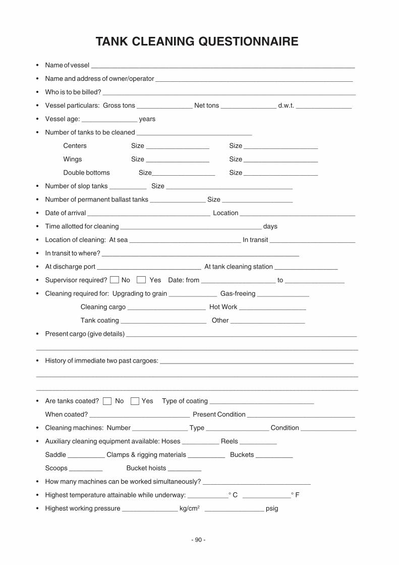
- 90 -
TANK CLEANING QUESTIONNAIRE
• Name of vessel _______________________________________________________________________
• Name and address of owner/operator _____________________________________________________
• Who is to be billed? ____________________________________________________________________
• Vessel particulars: Gross tons _______________ Net tons _______________ d.w.t. _______________
• Vessel age: _______________ years
• Number of tanks to be cleaned _______________________________
Centers Size _________________ Size ____________________
Wings Size _________________ Size ____________________
Double bottoms Size_________________ Size ____________________
• Number of slop tanks __________ Size __________________________________
• Number of permanent ballast tanks _______________ Size ___________________
• Date of arrival _________________________________ Location _______________________________
• Time allotted for cleaning ______________________________________ days
• Location of cleaning: At sea ______________________________ In transit _______________________
• In transit to where? _____________________________________________________
• At discharge port ____________________________ At tank cleaning station _________________
• Supervisor required? No Yes Date: from ____________________ to ________________
• Cleaning required for: Upgrading to grain _____________ Gas-freeing ______________
Cleaning cargo _____________________ Hot Work __________________
Tank coating _______________________ Other ____________________
• Present cargo (give details) ______________________________________________________________
___________________________________________________________________________________________
• History of immediate two past cargoes: ____________________________________________________
___________________________________________________________________________________________
___________________________________________________________________________________________
• Are tanks coated? No Yes Type of coating ____________________________
When coated? ___________________________ Present Condition _____________________________
• Cleaning machines: Number _______________ Type _________________ Condition _______________
• Auxiliary cleaning equipment available: Hoses __________ Reels __________
Saddle __________ Clamps & rigging materials __________ Buckets __________
Scoops _________ Bucket hoists _________
• How many machines can be worked simultaneously? _____________________________
• Highest temperature attainable while underway: ___________° C _____________° F
• Highest working pressure _______________ kg/cm2 ________________ psig

- 91 -
• Number of crewmen available for underway cleaning __________________
• Loading port (new cargo) _______________________________________________
• Pumping system: Ring main ______________ Spur main ______________ Direct main _________________
• Is tank washing line common with deck service or fire line? ___________________________
• Number of stripping pumps (eductors) _____________________ Capacity _____________________
• Date of last major cleaning __________________________ For what reason ___________________________
__________________________________________________________________________________________
• Inert gas system available? No Yes Type _____________________________
• Are tanks fitted with heating coils? No Yes
Type ______________________________ Max Temp. _____________°C ________________°F
• Diagram of ship layout (Attach drawing showing tanks, cofferdams, pumproom position, etc.)
• Is air pressure available on deck? No Yes
• Is a permanent chemical tank fitted? No Yes
• At which port will chemicals be required? _______________________________________________
• Is a system available to wash by pre-mixed chemical solution, i.e. from:
Chemical tank ____________ Can solution be heated? No Yes
Slop tank ___________ Can solution be heated? No Yes
Cofferdam __________ Can solution be heated? No Yes
• Describe ventilation facilities: ____________________________________________________________
____________________________________________________________________________________
____________________________________________________________________________________
• Have Drew Marine Chemicals been used for tank cleaning before? No Yes
Type ______________________________ Results __________________________________________
_____________________________________________________________________________________________
• Have competitive tank cleaning chemicals been used before?
No Yes Whose?
______________________________________________________________
Results ______________________________________________________________________________
• Remarks_____________________________________________________________________________
_______________________________________________________________________________________
_______________________________________________________________________________________
_______________________________________________________________________________________
_________________________________________________________________________________________
_________________________________________________________________________________________
_________________________________________________________________________________________
Signed ______________________________________________ Date ____________________________
- 92 -
REFERENCES
The drawings and diagrams on pages 3 and 6 are:
• Reprinted with kind permission from BUTTERWORTH1 Tank Cleaning Machines, Inc., Houston, Texas.
• Copyright BUTTERWORTH Tank Cleaning Machines, Inc.
• Specifications subject to change without notice.
1Registered Trademark of Butterworth Tank Cleaning Machines, Inc.
- 93 -
INDEX
A
Abbreviations, iiAdditives, Paints, 14Air Hoses, 2Alkali, 121AMERGY® 222, 35AMEROID® OWS, 12, 17, 23, 26AMEROID RSR, 13, 17Animal Oils, 9-13A.P.I. No., 27, 36, 58-60, 76Atomization of Cleaning Chemicals, 22, 32, 33
B
Ballast, 34, 35Biodegradable, 11Brooms, 2BUTTERWORTH1 Holes, 7BUTTERWORTH K Type Machine, 3-5, 28-29BUTTERWORTH Machines, 3-5, 28-29BUTTERWORTH SSK Type Machine, 3, 5, 29BUTTERWORTH SK Type Machine, 3, 5, 29
C
Cargo, 1, 9-10, 14, 45-47Cargo Clusters, 2Cargo Line Cleaning, 27-28Cargo Pumps, 41Cargo Tanks, 7-8, 41Cargoes, Toxic Chemical, 45, 46, 47Cargoes, Waxy, 2, 22. 28. 29Certificate of Complete Cargo Discharge, 8Certification - Tank Cleaning Classification, 7-8Chemical Cleaners - Quantities Required, 25-27, 28-33, 48-53Chemical Cleaning Methods, 22-30Chemicals - Tank Cleaning Types, 11-13Chlorinated Rubber Coatings, 15, 16, 17Class A Crude Oil, 39Class B Crude Oil, 39Class C Crude Oil, 39Classification - Tank Cleaning, 7-8Cleaning Ballast Tanks, 30Cleaning Instruction Guide, 62-64Cleaning Method - Determination of, 28Cleaning Oil from Bilges, 23, 26Cleaning Recommendations with EDGE®,LACTM and DREWTM ABD 48-53, 61-64Cleaning Tanks, 19-21Cleaning, Time Required Calculations, 31Coal Products, 9
- 94 -
C (continued)
Coating Compatibility Certificate, 8Cofferdams, 22, 41Combustion Support Triangle, 42Compatibilities - Tank Cleaners/Coatings, 14-18Copper Corrosion Test, 18Corrosion, 14Corrosive Chemicals, 9, 41Couplings, Hose, 2Critical Dilution Line, 37, 38Cross-Reference Table, Tank Cleaning Product, 65-73Crude Oil, 9, 27-29, 34-40Crude Oil Specification Guide , 57-60Crude Oil Washing (COW), 34-40
D
Deck Accesses for Tank Cleaning Machines, 6Deck Water Supply Lines, 5Deodorizer, 12-13Detergent, 12, 13Direct Injection Chemical Cleaning Method, 22, 27, 29, 31, 48-50Direct Injection Chemical Equipment, 4Distillates of Coal, 19Distillates of Petroleum, 9Dosages for EDGE, LAC and DREW™ ABD Cleanings, 48-53Draining Tanks, 20DREW ABD, 13, 17, 46, 48-53, 61-64DREW AF, 13, 17, 21DREW BC, 13, 17DREW NBD, 13, 17DREW TC SEA, 12, 17, 22, 24, 31-32,61-64Drying Oils, 9, 20, 27, 46-49Drying Tanks, 20
E
Earthing Tank Cleaning Equipment, 44EDGE®, 12, 17, 21, 30, 48-51, 62-64Eductors, 6, 36Electricity, Static, 34, 43, 44Emulsifier, 11, 12Entry Into Cargo Tanks, 41, 42ENVIROCARE® 370, 12, 17ENVIROCARE 480, 12, 17ENVIROMATE® 2000, 13, 17Epoxy Coatings, 15, 16, 17Evaporation (Paints), 15Explosimeter, 44Explosions, 34, 35, 36-38, 41-44
F
Failures, Tank Surveys, 21Fats, 9, 45-57Fire and Explosion Hazards, 42Fire Detection, 43Fire or Combustion Support Triangle, 42Fires, 36, 37, 42-44Fish Oils, 9, 10, 46-49
- 95 -
F (continued)
Flammable-Explosive Mixture Graph, 38Flammable and Explosive Mixtures, 37-Flammable Vapors, 36-40Flashlights, 2Flue Gas, 36, 39, 40Flushing Tanks, 20Frames, 2, 9, 19Fuel Oil, 11Fumes, 9, 41, 45, 46
G
Gas Free Certificate, 7Gas Freeing, 7, 42Glossary of Terms, 75-88Grounding Tank Cleaning Equipment, 44Guide to Crude Oil Specifications Worldwide, 57-60
H
Hand Spray Cleaning, 22, 32, 33HDE-777™, 12,17Health Certificate, 8Heater, Tank Cleaning Water, 5, 6High Wax Crude Oils, 22, 27, 28Hoses, Air, 2Hot Water Cleaning, 20, 21, 27, 28Hydrophilic, 11
I
Ignition Sources, 42, 43IMO, 36, 39, 41Independent Surveyors Certificate, 8Inert Gas, Production of, 41-43Inorganic Zinc Coatings, 16, 17,
J
Jets - Water Pressure, 2, 33
K
K Machine - BUTTERWORTH1, 3, 6, 47-48
L
LAC™, 12, 17, 22, 30, 46, 48-53, 61-64LAC Cleanings - Precautions, 50, 51Lights, 2

- 96 -
L (continued)
Lipophilic, 11Liquid Cargoes, Types of, 9-10Load on Top Method (LOT), 36
M
Maximum Acceptable Concentration (MAC) of Toxic Vapors, 45Mineral Oils, 10MP Machine, 3Mops, 2Mucking, 6Mucking Winches, 2MUD CONDITIONER™, 13, 30
N
Nitric Acid, 18Non-Drying Oils, 9, 46-47, 48Nozzles - Tank Wash Machine, 3
O
OBO, 14O&GR™, 12, 17OSD/LT™, 12, 17, 61Oil, Cleaning from Bilges, 12, 23, 26Oxidation - Oils, 19, 49Oxidation - Paints, 14Oxygen Analyzer, 43Oxygen Deficiency, 41, 51
P
P-60 Machine, 3Paint Solvent, 14Paints, 15-17, 46, 48Palladium, Reagent, 18Passivation, Stainless Steel Tanks, 3Petroleum Products, 9pH, 18, 47Pigment, 14Polyester Coatings, 15, 16Polymerization - Drying, Semi-Drying Oils, 20, 27Polymerization - Paints, 14Polyurethane Coatings, 15, 16Pour Point, 27Precleaning, 7Precleaning Tank Survey, 7Protective Clothing, 22, 41, 45Pump (Tank Cleaning), 2, 28Pump Rooms, 41Pumps, Cargo, 41
- 97 -
Q
Quadrant Saddles, 2Quantity of Cleaners, 24-26, 28-29, 48-53
R
Rags, 2Recirculation Method, 22, 32, 50References, 92Regulations, 7-8, 34-36, 41Rinsing Tanks, 27Rock and Roll Cleaning Method, 24-27, 32, 48-49, 50
S
Safety, 41-44Saponifier, 11Sawdust, 2Scrapers, 2Semi-Drying Oils, 9, 14, 27, 46-47, 48Ship Structural Diagrams, 54-56SK Machine - BUTTERWORTH1, 3, 5, 29Slop Tank Cleaning, 27, 28Solvents, 10-14Spanners, 2Sparks, 43Spot Cleaning, 20-21, 50-51Square Root Table, 74Squeegee Mops, 2SSK Machine - BUTTERWORTH, 3, 5, 29Stainless Steel Tanks, 18Static Electricity, 34, 43, 44Steaming Tanks, 20Stripping Lines, 28Stripping Pump, 6Structural Diagrams, Ships, 54-56Surface Active Agent (Surfactant), 11Survey Tanks, 7, 8
T
Tank Cleaning - Chemicals, 11-13Tank Cleaning Guide, 62-64Tank Cleaning Machine - Discharge Rates, 3Tank Cleaning Machine Cycles - Determination of Number, 28-29Tank Cleaning Deck Accesses, 5Tank Cleaning Inlet Pressures, 2Tank Cleaning Machines, 3-6Tank Cleaning Methods, 22-27Tank Cleaning Procedure, 19-21Tank Cleaning Product Cross-Reference Charts, 61-73Tank Cleaning Pump, 2, 3, 27Tank Cleaning Questionnaire, 89-91Tank Cleaning - System Components, 2-6Tank Cleaning Water Heater, 5
- 98 -
T (continued)
Tank Coating, Problems with, 18Tank Coatings, 14-18Tank Coatings, Maintenance of, 15Tank Intervals, 54-56Tank Survey, Failures, 20-21Tank Vessel Internal Structure - 54-56Tank Washing Machine, 6Tanker Safety Code (Guide), 41Tankers, 14TC#4™, 11, 17, 22, 23, 25, 30, 31, 32, 61-64Threshold Limit Value (TLV), 45Torches, 2Toxic Chemical Cargoes, 45, 46Toxic Hazards, 45, 46, 51Toxic Vapor Stain Tubes, 44Transverse Section of a Tanker, 55
U
Units, iiiUpgrading, 22, 31
V
Vapors - Dangerous, 36-44Vegetable Oil, 9, 46-47, 51Vehicle, Paint, 14Ventilation, 9, 41, 42
W
Wash Hoses, 2Wash (Tank Cleaning) Machines, 2-6Water Soluble Products, 9, 47Water Jet Pressure, 2, 33Waxy Cargoes, 19, 23, 27, 28Winches, Mucking, 2
Z
Zinc Silicate Coatings, 16-17, 47
Recommended


![Tank Cleaning Presentation · Title: Tank Cleaning Presentation [Compatibility Mode] Keywords ()](https://img.dokumen.tips/doc/110x75/5e7ee9464c9b0f56c8137b71/tank-cleaning-presentation-title-tank-cleaning-presentation-compatibility-mode.jpg)