DRAFT-Not for Implementation
J:\!GUIDANC\FINAL\1721DFT.WPD03/06/98
Guidance for IndustrySUPAC-IR/MR: Immediate Release andModified Release Solid Oral Dosage Forms
Manufacturing Equipment Addendum
Additional copies are available from:
Office of Training and Communications Division of Communications ManagementThe Drug Information Branch, HFD-210
5600 Fishers LaneRockville, MD 20857
(Tel) 301-827-4573(Internet) http://www.fda.gov/cder/guidance/index.htm
U.S. Department of Health and Human ServicesFood and Drug Administration
Center for Drug Evaluation and Research (CDER)April 1998
CMC X

DRAFT-Not for Implementation
J:\!GUIDANC\FINAL\1721DFT.WPD03/06/98 i
TABLE OF CONTENTS
I. INTRODUCTION . . . . . . . . . . . . . . . . . . . . . . . . . . . . . . . . . . . . . . . . . . . . . . . . . . . . 1
II. PARTICLE SIZE REDUCTION/SEPARATION . . . . . . . . . . . . . . . . . . . . . . . . . . . 3
III. BLENDING AND MIXING . . . . . . . . . . . . . . . . . . . . . . . . . . . . . . . . . . . . . . . . . . . . 9
IV. GRANULATION . . . . . . . . . . . . . . . . . . . . . . . . . . . . . . . . . . . . . . . . . . . . . . . . . . . . 14
V. DRYING . . . . . . . . . . . . . . . . . . . . . . . . . . . . . . . . . . . . . . . . . . . . . . . . . . . . . . . . . . 20
VI. UNIT DOSING . . . . . . . . . . . . . . . . . . . . . . . . . . . . . . . . . . . . . . . . . . . . . . . . . . . . . 26
VII. SOFT GELATIN CAPSULES . . . . . . . . . . . . . . . . . . . . . . . . . . . . . . . . . . . . . . . . . 29
VIII. COATING/PRINTING/DRILLING . . . . . . . . . . . . . . . . . . . . . . . . . . . . . . . . . . . . . 37

DRAFT-Not for Implementation
This guidance has been prepared under the auspices of the Chemistry, Manufacturing, and Controls1
Coordinating Committee in the Center for Drug Evaluation and Research (CDER) and the Office of Regulatory Affairs(ORA) at the Food and Drug Administration with the assistance of the International Society of PharmaceuticalEngineering (ISPE). This guidance represents the Agency's current thinking on equipment changes under SUPAC-IRand SUPAC-MR. It does not create or confer any rights for or on any person and does not operate to bind the FDA orthe public. An alternative approach may be used if such approach satisfies the requirements of the applicable statute,regulations or both.
J:\!GUIDANC\FINAL\1721DFT.WPD03/06/98
GUIDANCE FOR INDUSTRY 1
SUPAC-IR/MR: Immediate Release and Modified Release Solid Oral DosageForms Manufacturing Equipment Addendum
I. INTRODUCTION
The purpose of this guidance is to provide recommendations to pharmaceutical manufacturersusing the Center for Drug Evaluation and Research's Guidance for Industry: Immediate ReleaseSolid Oral Dosage Forms — Scale-Up and Post-Approval Changes: Chemistry, Manufacturingand Controls, In Vitro Dissolution Testing, and In Vivo Bioequivalence Documentation(SUPAC-IR), which published in November 1995, and Guidance for Industry: SUPAC-MR: Modified Release Solid Oral Dosage Forms Scale-Up and Post-Approval Changes: Chemistry,Manufacturing and Controls; In Vitro Dissolution Testing and In Vivo BioequivalenceDocumentation, which published in October 1997. This document was developed by the U.S.Food and Drug Administration (FDA) with the assistance of the International Society ofPharmaceutical Engineering (ISPE). This document extends and supercedes the ManufacturingEquipment Addendum published in October 1997 that covered only immediate release solid oraldosage forms.
The document should be used in conjunction with the SUPAC-IR and SUPAC-MR guidancedocuments in determining what documentation should be submitted to FDA regarding equipmentchanges made in accordance with the recommendations in sections V and VI.A of the SUPAC-IRguidance document and in sections VI and VII of the SUPAC-MR guidance document. TheSUPAC guidance documents define (1) levels of change; (2) recommended chemistry,manufacturing, and controls tests for each level of change; (3) in vitro dissolution tests and/or invivo bioequivalence tests for each level of change; and (4) documentation that should support thechange for new drug applications (NDAs) and abbreviated new drug applications (ANDAs).
This document is only an aid and, in some cases, specific equipment may not be listed. It does,however, include a representative list of equipment commonly used in the industry. The guidancedoes not address equipment that has been modified by a pharmaceutical manufacturer to fit its

DRAFT-Not for Implementation
J:\!GUIDANC\FINAL\1721DFT.WPD03/06/98 2
specific needs. If questions arise in using this guidance document please contact the appropriatereviewing office at CDER.
Although this guidance does not discuss validation, any equipment changes should be validated inaccordance with current good manufacturing practices (cGMPs) and the resulting data will besubject to examination by field investigators during routine GMP inspections. The information ispresented in broad categories of unit operation (blending and mixing, drying, particle sizereduction/separation, granulation, unit dosage, coating and printing, soft gelatin capsuleencapsulation). Definitions and classification are provided. For each operation, a table ispresented that categorizes equipment by class (operating principle) and subclass (designcharacteristic). Examples are given within the subclasses.
Equipment within the same class and subclass would be considered to have the same design andoperating principle under SUPAC-IR and SUPAC-MR. Therefore, for example, a change fromone type of diffusion mixer (e.g, V-blender from manufacturer A) to another diffusion mixer (e.g.,V-blender from manufacturer B) generally would not represent a change in operating principleand would, therefore, be considered to be the same under either SUPAC-IR or SUPAC-MR.
A change from equipment in one class to equipment in a different class would usually beconsidered a change in design and operating principle. For example, a change from a V-blenderto a ribbon blender demonstrates a change in the operating principle from diffusion blending toconvection blending and would be considered to be different under either SUPAC-IR or SUPAC-MR.
For modified release dosage forms, a change in equipment within the same class but to a differentsubclass would usually be considered a change in equipment to a different design and operatingprinciples under SUPAC-MR if it involves a unit operation critical to drug release.
Applicants should carefully consider and evaluate on a case-by-case basis changes in equipmentthat are in the same class, but different subclass. In many situations, this type of change inequipment would be considered similar, provided the unit operation is not critical to drug releasefor a modified release dosage form. For example, within the Blending and Mixing section, underthe Diffusion Mixers Class, a change from a V-blender (sub-class) to a Bin tumbler (sub-class)represents a change within a class and between sub-classes. Provided the manufacturing processwith the new equipment is validated and that this operation is not critical to drug release for amodified release dosage form, this change would likely not need a pre-approval supplement. Theapplicant should have available at the time of the change the scientific data and rationale used tomake this determination. This information is subject to FDA review at its discretion. It is up tothe applicant to determine the filing requirement.
This guidance will be updated as needed to reflect the introduction and discontinuation of specific

DRAFT-Not for Implementation
J:\!GUIDANC\FINAL\1721DFT.WPD03/06/98 3
types of manufacturing equipment. Manufacturers of equipment are encouraged to help keep thedocument current by communicating changes to the Agency and by making suggestions regardingwhat equipment should be considered to be within the same class or subclass. The submittedinformation will be reviewed by FDA and incorporated in an updated guidance document asappropriate.
II. PARTICLE SIZE REDUCTION/SEPARATION
A. Definitions
1. Unit Operations
a. Particle Size Reduction: The mechanical process of breakingparticles into smaller pieces via one or more particle size reductionmechanisms. The mechanical process used generally is referred toas milling.
i. Particle - Refers to either a discrete crystal or a grouping ofcrystals, generally known as an agglomerate.
ii. Particle Size Reduction Mechanisms
C Impact - Particle size reduction by applying aninstantaneous force perpendicular to theparticle/agglomerate surface. The force can resultfrom particle-to-particle or particle-to-mill surfacecollision.
C Attrition - Particle size reduction by applying aforce in a direction parallel to the particle surface.
C Compression - Particle size reduction by applying aforce slowly (as compared to Impact) to the particlesurface in a direction toward the center of theparticle.
C Cutting - Particle size reduction by applying ashearing force to a material.
b. Particle Separation: Particle size classification according to

DRAFT-Not for Implementation
J:\!GUIDANC\FINAL\1721DFT.WPD03/06/98 4
particle size alone.
2. Operating Principles
a. Fluid Energy Milling
Particles are reduced in size as a result of high-speed particle-to-particle impact and/or attrition; also known as micronizing.
b. Impact Milling
Particles are reduced in size by high-speed mechanical impact orimpact with other particles; also known as milling, pulverizing, orcomminuting.
c. Cutting
Particles are reduced in size by mechanical shearing.
d. Compression Milling
Particles are reduced in sized by compression stress and shearbetween two surfaces.
e. Screening
Particles are reduced in size by mechanically induced attritionthrough a screen. This process commonly is referred to as millingor deagglomeration.
f. Tumble Milling
Particles are reduced in size by attrition utilizing grinding media.
g. Separating
Particles are segregated based upon particle size alone and withoutany significant particle size reduction. This process commonly isreferred to as screening or bolting.
B. Equipment Classifications

DRAFT-Not for Implementation
J:\!GUIDANC\FINAL\1721DFT.WPD03/06/98 5
1. Fluid Energy Mills
Fluid energy mill subclasses have no moving parts and primarily aredistinguished from one another by the configuration and/or shape of theirchambers, nozzles, and classifiers.
C Tangential JetC Loop/OvalC Opposed JetC Opposed Jet with Dynamic ClassifierC Fluidized BedC Fixed TargetC Moving Target
2. Impact Mills
Impact mill subclasses primarily are distinguished from one another by theconfiguration of the grinding heads, chamber grinding liners (if any), andclassifiers.
C Hammer Air SweptC Hammer ConventionalC Pin/DiscC Cage
3. Cutting Mills
Although cutting mills may differ from one another in whether the knivesare movable or fixed and in the classifier configuration, no cutting millsubclasses have been identified.
4. Compression Mills
Although compression mills may differ from one another in whether one orboth surfaces are moving, no compression mill subclasses have beenidentified.
5. Screening Mills
Screening mill subclasses primarily are distinguished from one another bythe rotating element.

DRAFT-Not for Implementation
J:\!GUIDANC\FINAL\1721DFT.WPD03/06/98 6
C Rotating ImpellerC Rotating ScreenC Oscillating Bar
6. Tumbling Mills
Tumbling mill subclasses primarily are distinguished from one another bythe grinding media used and by whether the mill is vibrated.
C Ball MediaC Rod MediaC Vibrating
7. Separators
Separator subclasses primarily are distinguished from one another by themechanical means used to induce particle movement.
C Vibratory/ShakerC Centrifugal

DRAFT-Not for Implementation
J:\!GUIDANC\FINAL\1721DFT.WPD03/06/98 7
Table 1 Unit Operation - Particle Size Reduction
Class Subclass Examples
Fluid Energy Mills Tangential Jet Alpine (Hosokawa)Fluid Energy AljetSturtevant
Loop/Oval Fluid Energy Aljet
Opposed Jet Garlock
Opposed Jet with Dynamic Classifier Alpine (Hosokawa)Fluid Energy Aljet
Fluidized Bed None Identified
Fixed Target None Identified
Moving Target None Identified
Impact Mills Hammer Air Swept Alpine (Hosokawa)Bepex (Hosokawa)Sturtevant
Hammer Conventional Alpine (Hosokawa)FitzpatrickFluid AirMikro (Hosokawa)Rietz (Hosokawa)Stokes-Merrill
Pin/Disc Alpine (Hosokawa)KemutecSturtevant
Cage Stedman
Cutting Mills None Identified Alpine (Hosokawa)FitzpatrickUrschel
Compression Mills None Identified MCA International

DRAFT-Not for Implementation
J:\!GUIDANC\FINAL\1721DFT.WPD03/06/98 8
Table 1 Unit Operation - Particle Size Reduction (cont.)
Class Subclass Examples
Screening Mills Rotating Impeller Bepex (Hosokawa)FitzpatrickFluid AirKemutecQuadroStokes-MerrillZanchetta (Romaco)
Rotating Screen Glatt
Oscillating Bar Bepex (Hosokawa)FrewittJackson-CrockattStokes-MerrillVector
Tumbling Mills Ball Media US Stoneware
Rod Media None Identified
Vibrating Sweco
Table 2 Unit Operation - Separation
Class Subclass Examples
Separators Vibratory/Shaker AllgaierMcLanahanRotexRussell FinexSwecoVortiSiv
Centrifugal AZOKasonKemutecSweco

DRAFT-Not for Implementation
J:\!GUIDANC\FINAL\1721DFT.WPD03/06/98 9
III. BLENDING AND MIXING
A. Definitions
1. Unit Operations
Blending and Mixing: The reorientation of particles relative to oneanother in order to achieve uniformity.
2. Operating Principles
a. Diffusion Blending (Tumble)
Particles are reoriented in relation to one another when they areplaced in random motion and interparticular friction is reduced asthe result of bed expansion (usually within a rotating container);also known as tumble blending.
b. Convection Mixing
Particles are reoriented in relation to one another as a result ofmechanical movement; also known as paddle or plow mixing.
c. Pneumatic Mixing
Particles are reoriented in relation to one another as a result of theexpansion of a powder bed by gas.
B. Equipment Classifications
1. Diffusion Mixers (Tumble)
Diffusion mixer subclasses primarily are distinguished by geometric shapeand the positioning of the axis of rotation.
C V-blendersC Double Cone BlendersC Slant Cone BlendersC Cube BlendersC Bin BlendersC Horizontal/Vertical/Drum Blenders

DRAFT-Not for Implementation
J:\!GUIDANC\FINAL\1721DFT.WPD03/06/98 10
C Static Continuous BlendersC Dynamic Continuous Blenders
2. Convection Mixers
Convection blender subclasses primarily are distinguished by vessel shapeand impeller geometry:
C Ribbon BlendersC Orbiting Screw BlendersC Planetary BlendersC Forberg BlendersC Horizontal Double Arm BlendersC Horizontal High Intensity MixersC Vertical High Intensity MixersC Diffusion Mixers (Tumble) with Intensifier/Agitator
3. Pneumatic Mixers
Although pneumatic mixers may differ from one another in vesselgeometry, air nozzle type, and air nozzle configuration, no pneumaticmixer subclasses have been identified.
DRAFT-Not for Implementation
J:\!GUIDANC\FINAL\1721DFT.WPD03/06/98 11
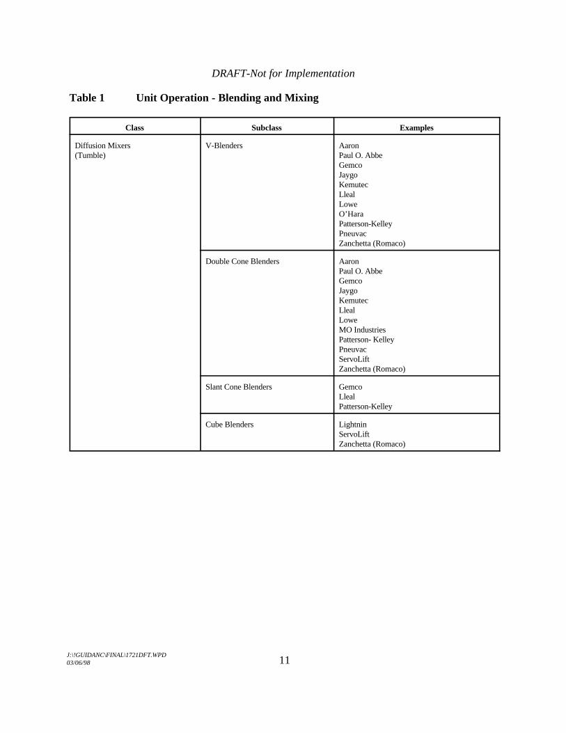
Table 1 Unit Operation - Blending and Mixing
Class Subclass Examples
Diffusion Mixers V-Blenders Aaron(Tumble) Paul O. Abbe
GemcoJaygoKemutecLlealLoweO’HaraPatterson-KelleyPneuvacZanchetta (Romaco)
Double Cone Blenders AaronPaul O. AbbeGemcoJaygoKemutecLlealLoweMO IndustriesPatterson- KelleyPneuvacServoLiftZanchetta (Romaco)
Slant Cone Blenders GemcoLlealPatterson-Kelley
Cube Blenders LightninServoLiftZanchetta (Romaco)

DRAFT-Not for Implementation
J:\!GUIDANC\FINAL\1721DFT.WPD03/06/98 12
Table 1 Unit Operation - Blending & Mixing (cont.)
Class Subclass Examples
Diffusion Mixers (Tumble) Bin Blenders Paul O. Abbe(cont.) L. B. Bohle
Cora InternationalCONSEPCreative Design & MachineCustom Metal CraftGEI-Gallay (GEI North America/Patriot)GemcoGlattJenike & JohansonKemutecMatcon, USAScholl (MO Industries)ServoLiftTote SystemsZanchetta (Romaco)
Horizontal/Vertical/Drum Blenders Munson Mill Machinery
Static Continuous Blenders Ross
Dynamic Continuous Blenders Patterson-Kelley
Convection Mixers Ribbon Blenders AaronPaul O. AbbeAutomatic Industry MachinesAzo-RubergCustom Metal CraftJaygoKemutecLowePneuvacRossVrieco-Nauta (Hosokawa)
Orbiting Screw Blenders AaronJaygoLittleford DayRossVrieco-Nauta (Hosokawa)

DRAFT-Not for Implementation
J:\!GUIDANC\FINAL\1721DFT.WPD03/06/98 13
Table 1 Unit Operation - Blending & Mixing (cont.)
Class Subclass Examples
Convection Mixers (cont.) Planetary Blenders AaronAeschbachAMFGEI-Collette (GEI North America/Vector)HobartJaygoLittleford DayRossVrieco
Forberg Blenders Paul O. AbbeDynamic Air
Horizontal Double Arm Blenders AaronPaul O. AbbeCustom Metal CraftDynamic AirJaygoKemutecLittleford DayRossSigmaTeledyne Readco
Horizontal High Intensity Mixers Littleford Day
Vertical High Intensity Mixers Aeromatic-Fielder (GEA-Niro)APVL.B. BohleDierks & ShoneGEI-Collette (GEI North America/Vector)Key InternationalLittleford DayPowrex (Glatt)Zanchetta (Romaco)
Diffusion Mixers (Tumble) with Paul O. AbbeIntensifier/Agitator Gemco
Patterson-Kelley
Pneumatic Mixers None Identified Dynamic AirReimelt

DRAFT-Not for Implementation
J:\!GUIDANC\FINAL\1721DFT.WPD03/06/98 14
IV. GRANULATION
A. Definitions
1. Unit Operations
Granulation: The process of creating granules. The powder morphologyis modified through the use of either a liquid that causes particles to bindthrough capillary forces or dry compaction forces. The process will resultin one or more of the following powder properties: enhanced flow;increased compressibility; densification; alteration of physical appearanceto more spherical, uniform, or larger particles; and/or enhancedhydrophilic surface properties.
2. Operating Principles
a. Dry Granulation
Dry powder densification and/or agglomeration by direct physicalcompaction.
b. Wet High-Shear Granulation
Powder densification and/or agglomeration by the incorporation ofa granulation fluid into the powder with high-power-per-unit mass,through rotating high-shear forces.
c. Wet Low-Shear Granulation
Powder densification and/or agglomeration by the incorporation ofa granulation fluid into the powder with low-power-per-unit mass,through rotating low-shear forces.
d. Low-Shear Tumble Granulation
Powder densification and/or agglomeration by the incorporation ofa granulation fluid into the powder with low-power-per-unit mass,through rotation of the container vessel and/or intensifier bar.
e. Extrusion Granulation

DRAFT-Not for Implementation
J:\!GUIDANC\FINAL\1721DFT.WPD03/06/98 15
Plasticization of solids or wetted mass of solids and granulationfluid with linear shear through a sized orifice using a pressuregradient.
f. Rotary Granulation
Spheronization, agglomeration, and/or densification of a wetted ornon-wetted powder or extruded material. This is accomplished bycentrifugal or rotational forces from a central rotating disk,rotating walls, or both. The process may include the incorporationand/or drying of a granulation fluid.
g. Fluid Bed Granulation
Powder densification and/or agglomeration with little or no shearby direct granulation fluid atomization and impingement on solids,while suspended by a controlled gas stream, with simultaneousdrying.
h. Spray Dry Granulation
A pumpable granulating liquid containing solids (in solution orsuspension) is atomized in a drying chamber and rapidly dried by acontrolled gas stream, producing a dry powder.
B. Equipment Classification
1. Dry Granulator
Dry granulator subclasses primarily are distinguished by the densificationforce application mechanism.
C SluggingC Roller Compaction
2. Wet High-Shear Granulator
Wet high-shear granulator subclasses primarily are distinguished by thegeometric positioning of the primary impellers; impellers can be top,bottom, or side driven.

DRAFT-Not for Implementation
J:\!GUIDANC\FINAL\1721DFT.WPD03/06/98 16
C Top or Bottom DrivenC Side Driven
3. Wet Low-Shear Granulator
Wet low-shear granulator subclasses primarily are distinguished by thegeometry and design of the shear inducing components; shear can beinduced by rotating impeller, reciprocal kneading action, or convectionscrew action.
C PlanetaryC KneadingC Screw
4. Low-Shear Tumble Granulator
Although low-shear tumble granulators may differ from one another invessel geometry and type of dispersion or intensifier bar, no low-sheartumble granulator subclasses have been identified.
5. Extrusion Granulator
Extrusion granulator subclasses primarily are distinguished by theorientation of extrusion surfaces and driving pressure productionmechanism.
C Radial or BasketC AxialC RamC Roller, Gear, or Pelletizer
6. Rotary Granulator
Rotary granulator subclasses primarily are distinguished by their structuralarchitecture. They have either open top architecture, such as a verticalcentrifugal spheronizer, or closed top architecture, such as a closed topfluid bed dryer.
C OpenC Closed

DRAFT-Not for Implementation
J:\!GUIDANC\FINAL\1721DFT.WPD03/06/98 17
7. Fluid Bed Granulator
Although fluid bed granulators may differ from one another in geometry,operating pressures, and other conditions, no fluid bed granulatorsubclasses have been identified.
8. Spray Dry Granulator
Although spray dry granulators may differ from one another in geometry,operating pressures, and other conditions, no spray dry granulatorsubclasses have been identified.
Note:If a single piece of equipment is capable of performing multiple discrete unit operations (mixing,granulating, drying), the unit was evaluated solely for its ability to granulate. If multifunctionalunits were incapable of discrete steps (fluid bed granulator/drier), the unit was evaluated as anintegrated unit.

DRAFT-Not for Implementation
J:\!GUIDANC\FINAL\1721DFT.WPD03/06/98 18
Table 1 Unit Operation - Granulation
Class Subclass Examples
Dry Granulator Slugging Various
Roller Compaction AlexanderwerkBepex (Hosokawa)FitzpatrickFreundVector
Wet High Shear Granulator Top Driven, or Bottom Driven Aeromatic-Fielder (GEA-Niro)Baker-PerkinsL.B. BohleDiosnaGEI-Collette (GEI North America/Vector)KeyLittleford DayPowrex (Glatt)Werner & PfeidererZanchetta (Romaco)
Side Driven Lodige
Wet Low Shear Granulator Planetary AaronAeschbachAMFGEI-Collette (GEI North America/Vector)HobartJaygoLittleford DayRossVrieco
Kneading AaronPaul O. AbbeCustom Metal CraftDynamic AirJaygoKemutecLittleford DayRossSigmaTeledyne Readco
Screw Vrieco-Nauta (Hosokawa)
Low Shear Tumble Granulator Slant Cone, or Double Cone, or V- Paul O. AbbeBlender Gemco
Patterson-Kelley

DRAFT-Not for Implementation
J:\!GUIDANC\FINAL\1721DFT.WPD03/06/98 19
Table 1 Unit Operation - Granulation (cont.)
Class Subclass Examples
Extrusion Granulator Radial or Basket AlexanderwerkGEA NiroLCILuwaRoss
Axial Bepex (Hosokawa)GablerLCI
Ram LCI
Roller, Gear, or Pelletizer AlexanderwerkBepex (Hosokawa)
Rotary Granulator Open Freund (Vector)GEA NiroLCILuwa
Closed Aeromatic-Fielder (GEA Niro)GlattLCIVector
Fluid Bed Granulator None Identified Aeromatic-Fielder (GEA Niro)APVBWI Hüttlin (Thomas Engineering)DiosnaFitzpatrickFluid AirGlattHeinenVector
Spray Dry Granulator None Identified AllgaierGEA NiroGlattHeinen
DRAFT-Not for Implementation
J:\!GUIDANC\FINAL\1721DFT.WPD03/06/98 20
V. DRYING
A. Definitions
1. Unit Operation
Drying: The removal of a liquid from a solid by evaporation.
2. Operating Principles
a. Direct Heating, Static Solids Bed
Heat transfer is accomplished by direct contact between the wetsolids and hot gases. The vaporized liquid is carried away by thedrying gases. There is no relative motion among solid particles.The solids bed exists as a dense bed, with the particles resting uponone another.
b. Direct Heating, Moving Solids Bed
Heat transfer is accomplished by direct contact between the wetsolids and hot gases. The vaporized liquid is carried away by thedrying gases. Solids motion is achieved by either mechanicalagitation or gravity force, which slightly expands the bed enoughto flow one particle over another.
c. Direct Heating, Fluidized Solids Bed
Heat transfer is accomplished by direct contact between the wetsolids and hot gases. The vaporized liquid is carried away by thedrying gases. The solids are in an expanded condition, with theparticles supported by drag forces caused by the gas phase. Thesolids and gases intermix and behave like a boiling liquid. Thisprocess commonly is referred to as fluid bed drying.
d. Direct Heating, Dilute Solids Bed, Spray Drying
Heat transfer is accomplished by direct contact between a highlydispersed liquid and hot gases. The feed liquid may be a solution,slurry, emulsion, gel or paste, provided it is pumpable and capableof being atomized. The fluid is dispersed as fine droplets into a

DRAFT-Not for Implementation
J:\!GUIDANC\FINAL\1721DFT.WPD03/06/98 21
moving stream of hot gases, where they evaporate rapidly beforereaching the wall of the drying chamber. The vaporized liquid iscarried away by the drying gases. The solids are fully expandedand so widely separated that they exert essentially no influence onone another.
e. Direct Heating, Dilute Solids Bed, Flash Drying
Heat transfer is accomplished by direct contact between wet solidsand hot gases. The solid mass is suspended in a finely divided statein a high-velocity and high-temperature gas stream. The vaporizedliquid is carried away by the drying gases.
f. Indirect Conduction, Moving Solids Bed
Heat transfer to the wet solid is through a retaining wall. Thevaporized liquid is removed independently from the heatingmedium. Solids motion is achieved by either mechanical agitationor gravity force, which slightly expands the bed enough to flowone particle over another.
g. Indirect Conduction, Static Solids Bed
Heat transfer to the wet solid is through a retaining wall. Thevaporized liquid is removed independently from the heatingmedium. There is no relative motion among solid particles. Thesolids bed exists as a dense bed, with the particles resting upon oneanother.
h. Indirect Conduction, Lyophilization
Drying in which the water vapor sublimes from the product afterfreezing.
i. Gas Stripping
Heat transfer is a combination of direct and indirect heating. Thesolids motion is achieved by agitation and the bed is partiallyfluidized.
j. Indirect Radiant, Moving Solids Bed

DRAFT-Not for Implementation
J:\!GUIDANC\FINAL\1721DFT.WPD03/06/98 22
Heat transfer is accomplished with varying wavelengths of energy. Vaporized liquid is removed independently from the solids bed. The solids motion is achieved by mechanical agitation, whichslightly expands the bed enough to flow one particle over oneanother. This process commonly is referred to as microwavedrying.
B. Equipment Classifications
1. Direct Heating, Static Solids Bed
Static solids bed subclasses primarily are distinguished by the method ofmoving the solids into the dryer.
C Tray and TruckC Belt
2. Direct Heating, Moving Solids Bed
Moving solids bed subclasses primarily are distinguished by the method ortechnology for moving the solids bed.
C Rotating TrayC Horizontal Vibrating Conveyor
3. Direct Heating, Fluidized Solids Bed (Fluid Bed Dryer)
Although fluid bed dryers may differ from one another in geometry,operating pressures, and other conditions, no fluidized solids bed dryersubclasses have been identified.
4. Direct Heating, Dilute Solids Bed, Spray Dryer
Although spray dryers may differ from one another in geometry, operatingpressures, and other conditions, no spray dryer subclasses have beenidentified.
5. Direct Heating, Dilute Solids Bed, Flash Dryer
Although flash dryers may differ from one another in geometry, operatingpressures, and other conditions, no flash dryer subclasses have been

DRAFT-Not for Implementation
J:\!GUIDANC\FINAL\1721DFT.WPD03/06/98 23
identified.
6. Indirect Conduction Heating, Moving Solids Bed
Moving solids bed subclasses primarily are distinguished by the method ortechnology for moving the solids bed.
C PaddleC Rotary (Tumble)C Agitation
7. Indirect Conduction Heating, Static Solids Beds
No indirect heating, static solids bed shelf dryer subclasses have beenidentified.
8. Indirect Conduction, Lyophilization
No lyophilizer subclasses have been identified.
9. Gas Stripping
Although gas stripping dryers may differ from one another in geometry,shape of agitator, and how fluidizing gas is moved through the bed, no gasstripping dryer subclasses have been identified.
10. Indirect Radiant Heating, Moving Solids Bed (Microwave Dryer)
Although microwave dryers may differ from one another in vesselgeometry and the way microwaves are directed into the solids, no indirectradiant heating, moving solids bed dryer subclasses have been identified.
Note:If a single piece of equipment is capable of performing multiple discrete unit operations (mixing,granulating, drying), the unit was evaluated solely for its ability to dry. The drying equipmentwas sorted into similar classes of equipment, based upon the method of heat transfer and thedynamics of the solids bed.

DRAFT-Not for Implementation
J:\!GUIDANC\FINAL\1721DFT.WPD03/06/98 24
Table 1 Unit Operation - Drying
Class Subclass Examples
Direct Heating, Static Solids Bed Tray and Truck ColtonDespatchGruenbergHot PackLydonO’HaraProctor & SchwartzTrent
Belt DespatchProctor & Schwartz
Direct Heating, Moving Solids Bed Rotating Tray Krauss MaffeiWyssmont
Horizontal Vibrating Conveyor CarrierWitte
Direct Heating, Fluidized Solids Bed None Identified Aeromatic-Fielder (GEA-Niro)(Fluid Bed Dryer) APV
BWI Hüttlin (Thomas Engineering)DiosnaFitzpatrickFluid AirGlattHeinenVector
Direct Heating, Dilute Solids Bed, None Identified AllgaierSpray Dryer APV
BWI Hüttlin (Thomas Engineering)GEA-NiroGlatt
Direct Heating, Dilute Solids Bed, None Identified AllgaierFlash Dryer APV
GEA-NiroMicron (Hosokawa)

DRAFT-Not for Implementation
J:\!GUIDANC\FINAL\1721DFT.WPD03/06/98 25
Table 1 Unit Operation - Drying (cont.)
Class Subclass Examples
Indirect Conduction, Moving Solids Paddle Bepex (Hosokawa)Bed Jaygo
Rotary (Tumble) Paul O. AbbeGemcoGlattLittleford DayPatterson-KelleyZanchetta (Romaco)
Agitation L. B. BohleDiosnaGEI-Collette (GEI North America)Krauss MaffeiVrieco-Nauta (Hosokawa)Zanchetta (Romaco)
Indirect Conduction, Static Solids None Identified HullBed
Indirect Conduction, Lyophilization None Identified AmscoHullSerailStokes
Gas Stripping None Identified Aeromatic-Fielder (GEA-Niro)L.B. BohleDiosnaGEI-Collette (GEI North America)Zanchetta (Romaco)
Indirect Radiant Heating, Moving None Identified Aeromatic-Fielder (GEA-Niro)Solids Bed (Microwave Dryer) L. B. Bohle
DiosnaGEI-Collette (GEI North America)
DRAFT-Not for Implementation
J:\!GUIDANC\FINAL\1721DFT.WPD03/06/98 26
VI. UNIT DOSING
A. Definitions
1. Unit Operation
Unit Dosing: The division of a powder blend into uniform single portionsfor delivery to patients.
2. Operating Principles
a. Tabletting
The division of a powder blend in which compression force isapplied to form a single unit dose.
b. Encapsulating
The division of a powder blend into a hard gelatin capsule.Encapsulators should all have the following operating principles incommon: rectification (orientation of the hard gelatin capsules),separation of capsule caps from bodies, dosing of fillmaterial/formulation, rejoining of caps and bodies, and ejection offilled capsules.
c. Powder Filling
Division of a powder blend into a container closure system.
B. Equipment Classifications
1. Tablet Press
Tablet press subclasses primarily are distinguished from one another by themethod that the powder blend is delivered to the die cavity. Tablet pressescan deliver powders without mechanical assistance (gravity), withmechanical assistance (power assisted), by rotational forces (centrifugal),and in two different locations where a tablet core is formed andsubsequently an outer layer of coating material is applied (compressioncoating).
DRAFT-Not for Implementation
J:\!GUIDANC\FINAL\1721DFT.WPD03/06/98 27
C GravityC Power AssistedC CentrifugalC Compression Coating
2. Encapsulator
Encapsulator subclasses primarily are distinguished from one another bythe method that is used for forming the powder blend into the slug.Encapsulators can deliver powders with a rotating auger, vacuum,vibration of perforated plate, tamping into a bored disk (dosing disk), orcylindrical tubes fitted with pistons (dosator).
C AugerC VacuumC VibratoryC Dosing DiskC Dosator
3. Powder Filler
Subclasses of powder fillers primarily are distinguished by the method usedto deliver the predetermined amount for container fill.
C VacuumC Auger

DRAFT-Not for Implementation
J:\!GUIDANC\FINAL\1721DFT.WPD03/06/98 28
Table 1 Unit Dosing
Class Subclass Examples
Tablet Press Gravity Colton (Vector)Manesty (Thomas Engineering)Stokes
Power Assisted Colton (Vector)Courtoy (AC Compacting)FetteHata (Elizabeth Carbide)KikusuiKilianManesty (Thomas Engineering)
Centrifugal Comprima (IMA)
Compression Coating Manesty (Thomas Engineering)Kikusui Kilian
Encapsulator Auger Capsugel Type BElanco No. 8
Vacuum Perry
Vibratory Osaka (Sharpley-Stokes)
Dosing Disk H&K/ BoschIndex
Dosator Macofar (Romaco)MG2Zanasi/Pharmatic/IMA
Powder Filler Vacuum BoschPerryZanasi
Auger All-FillCalumatic
DRAFT-Not for Implementation
J:\!GUIDANC\FINAL\1721DFT.WPD03/06/98 29
VII. SOFT GELATIN CAPSULES
A. Definitions
1. Unit Operations
a. Gel Mass Preparation: The manufacture of ahomogeneous, degassed liquid mass (solution) ofgelatin, plasticizer, water, and other additives, either insolution or suspension, such as colorants, pigments,flavors, preservatives, etc., that comprise a uniquefunctional gel shell formation. The operation may beperformed in discreet steps or by continuousprocessing. Minor components can be added after theliquid gel mass is made.
b. Fill Mixing: The mixing of either liquids or solids with otherliquids to form a solution; blending of limited solubility solid(s)with a liquid carrier and suspending agents used to stabilize theblend to form a suspension; or the uniform combination of dry inertand drug active substances to form a dry powder fill suitable forencapsulation. The reader should refer to the other sections of thisdocument for dry fill manufacture.
c. Core Enrobing: The gelatin coating of gravity or force fed pre-formed tablets or caplets.
d. Encapsulation: The continuous casting of gel ribbons, with liquidfill material being injected between the gel ribbons using a positivedisplacement pump or, for dry materials being gravity or force fedwith capsule formation using a rotary die.
e. Washing: The continuous removal of a lubricant material from theoutside of the formed capsule. The washing operation is unique toeach manufacturer's operation and generally uses in-housefabricated equipment. This equipment will not be discussed in thisguidance document.
f. Drying: The removal of the majority of water from the capsule'sgel shell by tumbling and subsequent tray drying using conditionedair, which enhances the size, shape, and shell physical properties of

DRAFT-Not for Implementation
Carstensen, J. T., “Theory of Pharmaceutical Systems, Volume 11 Heterogeneous Systems," Academic Press,2
New York, NY, 1973, p 51.
J:\!GUIDANC\FINAL\1721DFT.WPD03/06/98 30
the final product. The drying operation is unique to eachmanufacturer's operation and generally uses in-house fabricatedequipment. This equipment will not be discussed in this guidancedocument.
g. Inspection/Sorting: The process wherein undesirable capsules areremoved, including misshapen, leaking, and unfilled capsules aswell as agglomerates of capsules.
h. Printing: The marking of a capsule surface for the purpose ofproduct identification, using a suitable printing media or method.
2. Operating Principles
a. Mixing
The combination of solid and liquid components, includingsuspending aid(s) at either ambient or elevated temperatures toform a solution, suspension, or dry powder blend for themanufacture of gel mass or fill material. Mixing also includes theincorporation of minor components into the liquid gel mass.
b. Deaggregation
The removal of aggregates using a suitable homogenizer/mill toprovide a pumpable fill material. The procedure has minimal effecton the particle size distribution of the initial solid component(s),and is viewed as a processing aid.2
c. Deaeration
The removal of entrapped air from either the gel mass or fillmaterial, solution or suspension. This process can take place ineither the mixing vessel, through the application of vacuum, or aseparate off-line step.
d. Holding
The storage of liquid gel mass or fill material in a vessel, with a

DRAFT-Not for Implementation
Lachman, L., H. A. Lieberman, and J. L. Kanig (Eds.), The Theory and Practice of Industrial Pharmacy,3
Chapter 3, p. 359 (Stanley, J. P.), Philadelphia: Lea & Febiger, 1971.
Tyle, P. (Ed.), Specialized Drug Delivery Systems, Manufacturing and Production Technology, Chapter 10, p. 409(Wilkinson, P.K.and F.S. Hom), New York: M. Dekker, 1990.
Porter, S., Remington’s Pharmaceutical Sciences, Edition 18, Chapter 89, pp. 1662 - 1665, Easton, Penn.: MackPublishing Co.
J:\!GUIDANC\FINAL\1721DFT.WPD03/06/98 31
mixer or without, prior to encapsulation, which also may beequipped with a jacket for either heating or cooling.
e. Encapsulation
The formation of capsules using a rotary die machine.3
f. Inspection/Sorting
The physical removal of misshapen, leaking, or agglomeratedcapsules, using either a manual or automatic operation.
g. Printing
The user of this document is asked to refer to the coating/printingsection, in which the use of various pieces of equipment aredefined and categorized.
B. Equipment Classifications
1. Mixers and Mixing Vessels
Mixer and mixing vessel subclasses primarily are distinguished by themixing energy, mixer type, and whether a jacketed vessel with vacuumcapabilities is used in conjunction with a specific mixer.
C Low Energy MixerC High Energy MixerC PlanetaryC Jacketed Vessel With and Without VacuumC Conventional
2. Deaggregators

DRAFT-Not for Implementation
J:\!GUIDANC\FINAL\1721DFT.WPD03/06/98 32
Deaggregator subclasses primarily are distinguished by the type ofmechanical action imparted to the material.
C Rotor/StatorC RollerC Cutting MillsC Stone MillsC Tumbling Mills
3. Deaerators
Deaerator subclasses primarily are distinguished by the air removal path,either through the bulk or through a thin film, and whether it is a batch orin-line process.
C Vacuum VesselC Off Line/In Line
4. Holding Vessels
Although holding vessels may differ from one another, based uponwhether they are jacketed, with and without integrated mixing capabilities,no holding vessel subclasses have beeen identified.
5. Encapsulators
Encapsulator subclasses primarily are distinguished by the method used toinject the fill material.
C Positive Displacement PumpC Gravity or Force Fed
6. Inspection/Sorting
Inspection/sorting equipment subclasses primarily are distinguished by themethod used to present the capsule for viewing and mechanical method ofseparation.
C BeltC VibratoryC Roller

DRAFT-Not for Implementation
J:\!GUIDANC\FINAL\1721DFT.WPD03/06/98 33
C Rotary TableC Electromechanical

DRAFT-Not for Implementation
J:\!GUIDANC\FINAL\1721DFT.WPD03/06/98 34
Table 1 Unit Operation - Soft Gelatin Capsules
Class Subclass Examples
Mixers and Mixing Vessels Low Energy GEI-Collette (GEI North America/Vector) GEI-Kreiger (GEI North America)HobartKoruma (Romaco)LightninMoorhouse-CowlesQuadro
High Energy CowlesGEI-Collette (GEI North America/Vector)Koruma (Romaco)
Planetary AaronAeschbachAMFGEI-Collette (GEI North America/Vector)HobartJaygoLittleford DayRossVrieco
Jacketed with and without Vacuum BecomixFrymaGEI-Kreiger (GEI North America)HicksLee IndustriesPaul Mueller Co.RossKoruma (Romaco)
Conventional Lee Industries
DRAFT-Not for Implementation
J:\!GUIDANC\FINAL\1721DFT.WPD03/06/98 35
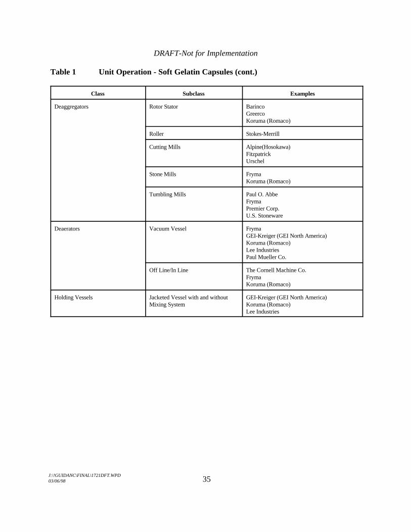
Table 1 Unit Operation - Soft Gelatin Capsules (cont.)
Class Subclass Examples
Deaggregators Rotor Stator BarincoGreerco Koruma (Romaco)
Roller Stokes-Merrill
Cutting Mills Alpine(Hosokawa)FitzpatrickUrschel
Stone Mills FrymaKoruma (Romaco)
Tumbling Mills Paul O. AbbeFrymaPremier Corp.U.S. Stoneware
Deaerators Vacuum Vessel FrymaGEI-Kreiger (GEI North America)Koruma (Romaco)Lee IndustriesPaul Mueller Co.
Off Line/In Line The Cornell Machine Co.FrymaKoruma (Romaco)
Holding Vessels Jacketed Vessel with and without GEI-Kreiger (GEI North America)Mixing System Koruma (Romaco)
Lee Industries
DRAFT-Not for Implementation
J:\!GUIDANC\FINAL\1721DFT.WPD03/06/98 36
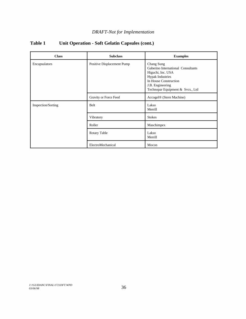
Table 1 Unit Operation - Soft Gelatin Capsules (cont.)
Class Subclass Examples
Encapsulators Positive Displacement Pump Chang SungGaberino International ConsultantsHiguchi, Inc. USAHypak IndustriesIn House ConstructionJ.B. EngineeringTechnopar Equipment & Svcs., Ltd
Gravity or Force Feed Accogel® (Stern Machine)
Inspection/Sorting Belt LaksoMerrill
Vibratory Stokes
Roller Maschimpex
Rotary Table LaksoMerrill
ElectroMechanical Mocon

DRAFT-Not for Implementation
J:\!GUIDANC\FINAL\1721DFT.WPD03/06/98 37
VIII. COATING/PRINTING/DRILLING
A. Definitions
1. Unit Operation
a. Coating: The uniform deposition of a layer of material on or around a solid dosage form, or component thereof, to:
C protect the drug from its surrounding environment (air,moisture, and light), with a view to improving stability.
C mask unpleasant taste, odor, or color of the drug.C increase the ease of ingesting the product for the patient.C impart a characteristic appearance to the tablets, which
facilitates product identification and aids patientcompliance.
C provide physical protection to facilitate handling. Thisincludes minimizing dust generation in subsequent unitoperations.
C reduce the risk of interaction between incompatiblecomponents. This would be achieved by coating one ormore of the offending ingredients.
C modify the release of drug from the dosage form. Thisincludes delaying, extending, and sustaining drug substancerelease.
The coating material deposition typically is accomplished throughone of four major techniques:
1. Sugar Coating - Deposition of coating material onto thesubstrate from aqueous solution/suspension of coatings,based predominately upon sucrose as a raw material.
2. Film Coating - The deposition of polymeric film onto thesolid dosage form.
3. Microencapsulation - The deposition of a coating materialonto a particle, pellet, granule, or bead core. The substratein this application ranges in size from submicron to severalmillimeters. It is this size range that differentiates it fromthe standard coating described in 1 and 2 above.
4. Compression Coating (This topic is addressed in the UnitDosing section.)
DRAFT-Not for Implementation
J:\!GUIDANC\FINAL\1721DFT.WPD03/06/98 38
b. Printing: The marking of a capsule or tablet surface for thepurpose of product identification. Printing may be accomplishedby either the application of a contrasting colored polymer (ink)onto the surface of a capsule or tablet, or by the use of laseretching.
The method of application, provided the ink formulation is notaltered, is of no consequence to the physical-chemical properties ofthe product.
c. Drilling: The drilling or ablating of a hole or holes through thepolymeric film coating shell on the surfaces of a solid oral dosageform using a laser. The polymeric film shell is not soluble in vivo. The hole or holes allow for the modified release of the drug fromthe core of the dosage form.
2. Operating Principles
a. Pan Coating
The uniform deposition of coating material onto the surface of asolid dosage form, or component thereof, while being translatedvia a rotating vessel.
b. Gas Suspension
The application of a coating material onto a solid dosage form, orcomponent thereof, while being entrained in a process gas stream.
Alternatively, this may be accomplished simultaneously by sprayingthe coating material and substrate into a process gas stream.
c. Vacuum Film Coating
This technique uses a jacketed pan equipped with a baffle system. Tablets are placed into the sealed pan, an inert gas (i.e. nitrogen) isused to displace the air and then a vacuum is drawn.
d. Dip Coating
Coating is applied to the substrate by dipping it into the coating

DRAFT-Not for Implementation
J:\!GUIDANC\FINAL\1721DFT.WPD03/06/98 39
material. Drying is accomplished using pan coating equipment.
e. Electrostatic Coating
A strong electrostatic charge is applied to the surface of thesubstrate. The coating material containing oppositely chargedionic species is sprayed onto the substrate.
f. Compression Coating
Refer to the Unit Dosing section of this document.
g. Ink-Based Printing
The application of contrasting colored polymer (ink) onto thesurface of a tablet or capsule.
h. Laser Etching
The application of identifying markings onto the surface of a tabletor capsule using laser-based technology.
i. Drilling
A drilling system typically is a custom built unit consisting of amaterial handling system to orient and hold the solid dosage form,a laser (or lasers), and optics (lenses, mirrors, deflectors, etc.) toablate the hole or holes, and controls. The drilling unit may includedebris extraction and inspection systems as well. The sorting,orienting, and holding equipment commonly is provided by dosageform printing equipment manufacturers, and is considered ancillaryin this use.
B. Equipment Classification
1. Pan Coating
Pan coating subclasses primarily are distinguished by the panconfiguration, the pan perforations, and/or the perforated device used tointroduce process air for drying purposes. Perforated coating systemsinclude both batch and continuous coating processes.

DRAFT-Not for Implementation
J:\!GUIDANC\FINAL\1721DFT.WPD03/06/98 40
C Conventional Coating SystemC Perforated Coating System
2. Gas Suspension
Gas suspension subclasses primarily are distinguished by the methodby which the coating is applied to the substrate.
C Fluidized BedC Spray Congealing/Drying
3. Vacuum Film Coating
Although there may be differences in the jacketed pan, baffle system, orvacuum source, no vacuum film coating subclasses have been identified.
4. Dip Coating
Because of the custom design associated with this class of coating, no dipcoating subclasses or examples have been identified.
5. Electrostatic Coating
Because of the custom design associated with this class of coating, noelectrostatic coating subclasses or examples have been identified.
6. Compression Coating
Refer to the Unit Dosing section of this document.
7. Ink-Based Printing
Ink-based printing subclasses primarily are distinguished by the method bywhich the marking is applied to a capsule or tablet surface.
C OffsetC Ink Jet
8. Laser Etching (Printing)
Although laser etching systems may differ from one another, no laser

DRAFT-Not for Implementation
J:\!GUIDANC\FINAL\1721DFT.WPD03/06/98 41
etching subclasses have been identified.
9. Drilling
The method of producing the laser pulse that ablates the hole(s) is of noconsequence to the physical-chemical properties of the product. Therefore, no dosage form drilling equipment subclasses have beenidentified.

DRAFT-Not for Implementation
J:\!GUIDANC\FINAL\1721DFT.WPD03/06/98 42
Table 1 Unit Operation - Coating Equipment
Class Subclass Examples
Pan Coating Conventional Coating BruckSystem O’Hara
PellegriniStokes-Merrill
Perforated Coating System BWI Hüttlin (Thomas Engineering)DriamGlattGS Coating SystemsNicomacO’HaraRaymondStrunckThomas EngineeringVector
Gas Suspension Fluidized Bed Aeromatic-Fielder (GEA Niro)L.B. BohleBWI Hüttlin (Thomas Engineering)Fluid AirGlattVector
Spray Congealing/Drying AllgaierAPVBWI Hüttlin (Thomas Engineering)GEA-NiroGlatt
Vacuum Film Coating None Identified Glatt
Dip Coating None Identified None Identified
Electrostatic Coating None Identified None Identified

DRAFT-Not for Implementation
J:\!GUIDANC\FINAL\1721DFT.WPD03/06/98 43
Table 2 Unit Operation - Printing Equipment
Class Subclass Examples
Ink-Based Printing Off Set AckleyHartnettMarkemTakeda
Ink Jet ImageLinx
Laser Etching (Printing) None Identified Lumonics
Table 3 Unit Operation - Drilling Equipment
Class Subclass Examples
Laser Drilling None Identified Convergent EnergiesCoherentThe Automation PartnerLumonics
Recommended